Embed Size (px)
Citation preview
© Copyright 2012 Cisco Systems, Inc. This document may be freely reproduced and distributed whole and intact including this Copyright Notice.
Nexus 7000 18 Slot
FIPS 140-2 Non-Proprietary Security Policy Level 1 Validation Document Version: Version 1.2 July 5, 2012
© Copyright 2012 Cisco Systems, Inc. Page 2 of 26 This document may be freely reproduced and distributed whole and intact including this Copyright Notice.
INTRODUCTION
Purpose This is a non-proprietary Cryptographic Module Security Policy for the Nexus 7000 18 Slot from Cisco Systems, Inc., referred to in this document as the module, appliance, or as previously stated. This security policy describes how modules meet the security requirements of FIPS 140-2 and how to run the modules in a FIPS 140-2 mode of operation.
This policy was prepared as part of the Level 1 FIPS 140-2 validation of the Nexus 7000 18 Slot.
FIPS 140-2 (Federal Information Processing Standards Publication 140-2 — Security Requirements for Cryptographic Modules) details the U.S. Government requirements for cryptographic modules. More information about the FIPS 140-2 standard and validation program is available on the NIST website at http://csrc.nist.gov/groups/STM/cmvp/
References This document deals only with operations and capabilities of the module in the technical terms of a FIPS 140-2 cryptographic module security policy. More information is available on the module from the following sources:
• The Cisco Systems, Inc. website (http://www.cisco.com) contains information on the full line of products from Cisco Systems, Inc.
• The NIST Cryptographic Module Validation Program website (http://csrc.nist.gov/groups/STM/cmvp/index.html) contains contact information for answers to technical or sales-related questions for the module.
Document Organization The Security Policy document is one document in the FIPS 140-2 Submission Package. In addition to this document, the Submission Package contains:
• Vendor Evidence • Finite State Machine • Other supporting documentation as additional references
With the exception of this Non-Proprietary Security Policy, the FIPS 140-2 Validation Documentation is proprietary to Cisco Systems, Inc. and is releasable only under appropriate non-disclosure agreements. For access to these documents, please contact Cisco Systems, Inc.
© Copyright 2012 Cisco Systems, Inc. Page 3 of 26 This document may be freely reproduced and distributed whole and intact including this Copyright Notice.
NEXUS 7000 18 SLOT FROM CISCO SYSTEMS, INC.
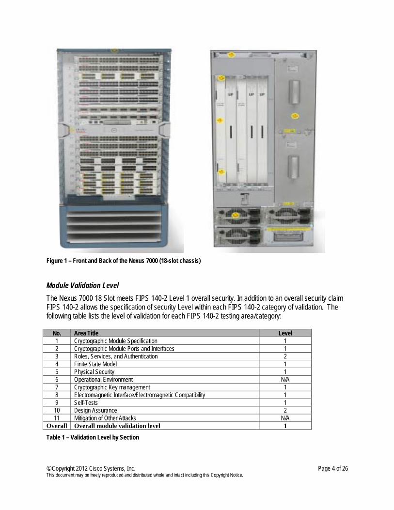
General Overview The Cisco Nexus 7000 18 Slot is a highly scalable in the Data Center end-to-end 10 Gigabit Ethernet switch for mission-critical data center operations. The fabric architecture scales beyond 15 terabits per second (Tbps), with future support for 40-Gbps and 100- Gbps Ethernet. Powered by Cisco NX-OS, a state of the art modular operating system, the platform is designed for exceptional scalability, continuous system operation, serviceability, and transport flexibility. The Cisco Nexus 7000 18 Slot provides comprehensive security features supported by a robust control plane and wire-rate encryption and decryption, allowing security controls that are less complex and more transparent to the protocols and applications in the data center. It supports Cisco TrustSec, a new architecture from Cisco for a converged policy framework to create role-aware networks and pervasive integrity and confidentiality. FIPS 140-2 Overview The Nexus 7000 18 Slot as defined within the scope of the FIPS 140-2 requirements is a multi-chip standalone Hardware device. The cryptographic boundary is the exterior Nexus 7000 18 Slot chassis which encompasses all components of the Nexus 7000 18 Slot (see figure 1), therefore ensuring that all components have undergone a thorough FIPS 140-2 testing and also are physically protected such that unauthorized access is detected.
© Copyright 2012 Cisco Systems, Inc. Page 4 of 26 This document may be freely reproduced and distributed whole and intact including this Copyright Notice.
Figure 1 – Front and Back of the Nexus 7000 (18-slot chassis)
Module Validation Level The Nexus 7000 18 Slot meets FIPS 140-2 Level 1 overall security. In addition to an overall security claim FIPS 140-2 allows the specification of security Level within each FIPS 140-2 category of validation. The following table lists the level of validation for each FIPS 140-2 testing area/category:
No. Area Title Level 1 Cryptographic Module Specification 1 2 Cryptographic Module Ports and Interfaces 1 3 Roles, Services, and Authentication 2 4 Finite State Model 1 5 Physical Security 1 6 Operational Environment N/A 7 Cryptographic Key management 1 8 Electromagnetic Interface/Electromagnetic Compatibility 1 9 Self-Tests 1 10 Design Assurance 2 11 Mitigation of Other Attacks N/A
Overall Overall module validation level 1
Table 1 – Validation Level by Section
© Copyright 2012 Cisco Systems, Inc. Page 5 of 26 This document may be freely reproduced and distributed whole and intact including this Copyright Notice.
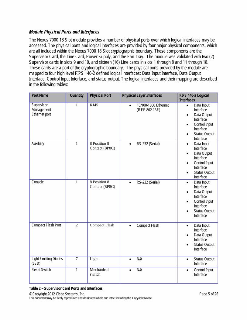
Module Physical Ports and Interfaces The Nexus 7000 18 Slot module provides a number of physical ports over which logical interfaces may be accessed. The physical ports and logical interfaces are provided by four major physical components, which are all included within the Nexus 7000 18 Slot cryptographic boundary. These components are the Supervisor Card, the Line Card, Power Supply, and the Fan Tray. The module was validated with two (2) Supervisor cards in slots 9 and 10, and sixteen (16) Line cards in slots 1 through 8 and 11 through 18. These cards are a part of the cryptographic boundary. The physical ports provided by the module are mapped to four high level FIPS 140-2 defined logical interfaces: Data Input Interface, Data Output Interface, Control Input Interface, and status output. The logical interfaces and their mapping are described in the following tables:
Port Name Quantity Physical Port Physical Layer Interfaces FIPS 140-2 Logical
Interfaces Supervisor Management Ethernet port
1 RJ45 • 10/100/1000 Ethernet (IEEE 802.1AE)
• Data Input Interface
• Data Output Interface
• Control Input Interface
• Status Output Interface
Auxiliary 1 8 Position 8 Contact (8P8C)
• RS-232 (Serial) • Data Input Interface
• Data Output Interface
• Control Input Interface
• Status Output Interface
Console 1 8 Position 8 Contact (8P8C)
• RS-232 (Serial) • Data Input Interface
• Data Output Interface
• Control Input Interface
• Status Output Interface
Compact Flash Port 2 Compact Flash • Compact Flash • Data Input Interface
• Data Output Interface
• Status Output Interface
Light Emitting Diodes (LED)
7 Light • N/A • Status Output Interface
Reset Switch 1 Mechanical switch
• N/A • Control Input Interface
Table 2 – Supervisor Card Ports and Interfaces
© Copyright 2012 Cisco Systems, Inc. Page 6 of 26 This document may be freely reproduced and distributed whole and intact including this Copyright Notice.
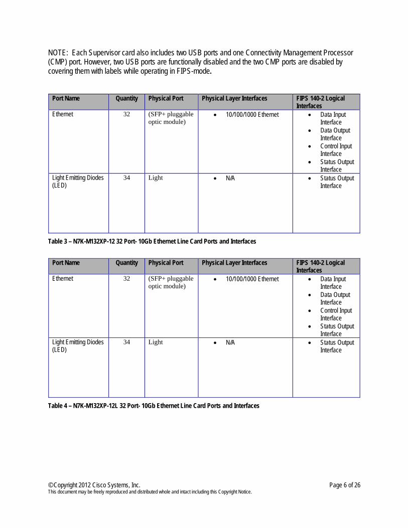
NOTE: Each Supervisor card also includes two USB ports and one Connectivity Management Processor (CMP) port. However, two USB ports are functionally disabled and the two CMP ports are disabled by covering them with labels while operating in FIPS-mode.
Port Name Quantity Physical Port Physical Layer Interfaces FIPS 140-2 Logical Interfaces
Ethernet 32 (SFP+ pluggable optic module)
• 10/100/1000 Ethernet • Data Input Interface
• Data Output Interface
• Control Input Interface
• Status Output Interface
Light Emitting Diodes (LED)
34 Light • N/A • Status Output Interface
Table 3 – N7K-M132XP-12 32 Port- 10Gb Ethernet Line Card Ports and Interfaces
Port Name Quantity Physical Port Physical Layer Interfaces FIPS 140-2 Logical
Interfaces Ethernet 32 (SFP+ pluggable
optic module) • 10/100/1000 Ethernet • Data Input
Interface • Data Output
Interface • Control Input
Interface • Status Output
Interface Light Emitting Diodes (LED)
34 Light • N/A • Status Output Interface
Table 4 – N7K-M132XP-12L 32 Port- 10Gb Ethernet Line Card Ports and Interfaces
© Copyright 2012 Cisco Systems, Inc. Page 7 of 26 This document may be freely reproduced and distributed whole and intact including this Copyright Notice.
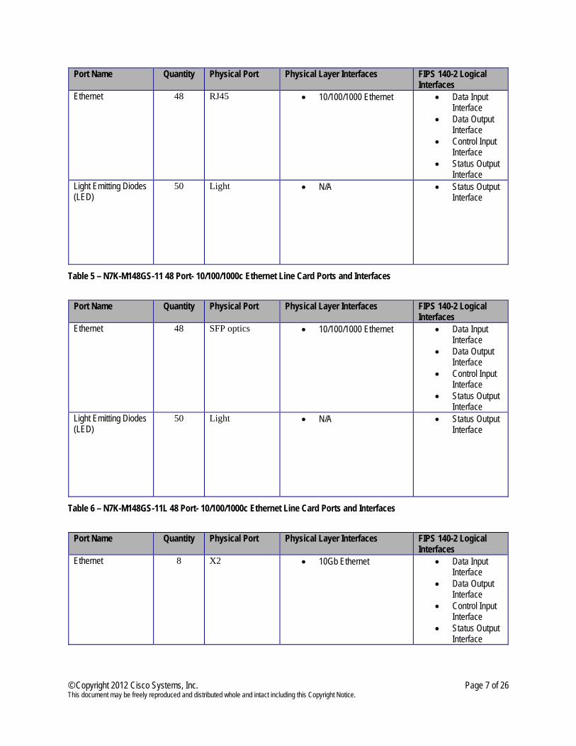
Port Name Quantity Physical Port Physical Layer Interfaces FIPS 140-2 Logical Interfaces
Ethernet 48 RJ45 • 10/100/1000 Ethernet • Data Input Interface
• Data Output Interface
• Control Input Interface
• Status Output Interface
Light Emitting Diodes (LED)
50 Light • N/A • Status Output Interface
Table 5 – N7K-M148GS-11 48 Port- 10/100/1000c Ethernet Line Card Ports and Interfaces
Port Name Quantity Physical Port Physical Layer Interfaces FIPS 140-2 Logical
Interfaces Ethernet 48 SFP optics • 10/100/1000 Ethernet • Data Input
Interface • Data Output
Interface • Control Input
Interface • Status Output
Interface Light Emitting Diodes (LED)
50 Light • N/A • Status Output Interface
Table 6 – N7K-M148GS-11L 48 Port- 10/100/1000c Ethernet Line Card Ports and Interfaces
Port Name Quantity Physical Port Physical Layer Interfaces FIPS 140-2 Logical
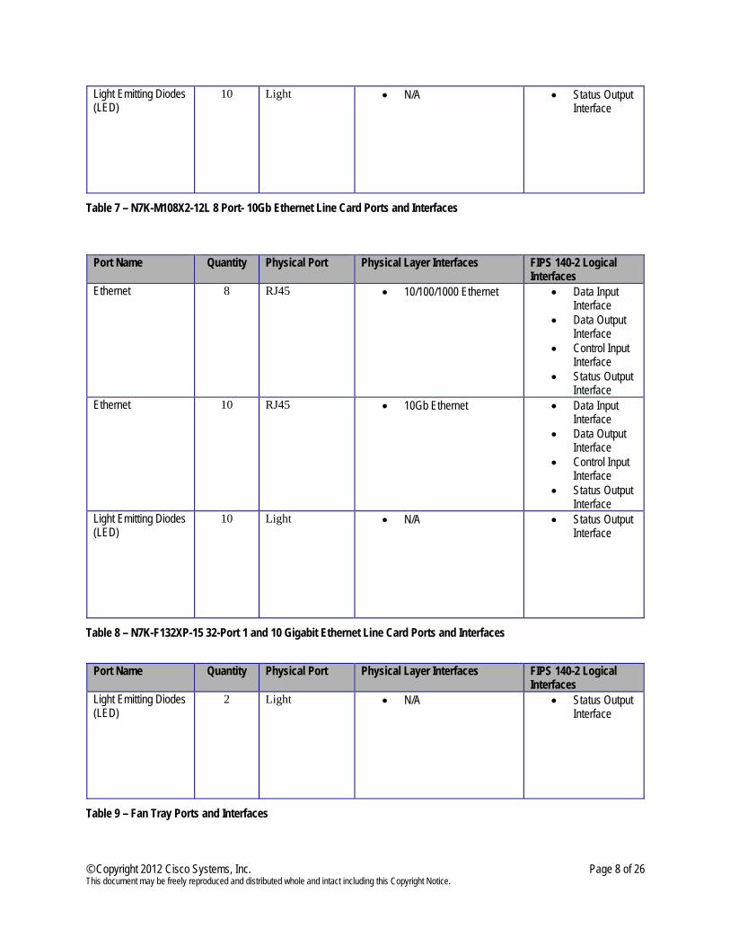
Interfaces Ethernet 8 X2 • 10Gb Ethernet • Data Input
Interface • Data Output
Interface • Control Input
Interface • Status Output
Interface
© Copyright 2012 Cisco Systems, Inc. Page 8 of 26 This document may be freely reproduced and distributed whole and intact including this Copyright Notice.
Light Emitting Diodes (LED)
10 Light • N/A • Status Output Interface
Table 7 – N7K-M108X2-12L 8 Port- 10Gb Ethernet Line Card Ports and Interfaces
Port Name Quantity Physical Port Physical Layer Interfaces FIPS 140-2 Logical Interfaces
Ethernet 8 RJ45 • 10/100/1000 Ethernet • Data Input Interface
• Data Output Interface
• Control Input Interface
• Status Output Interface
Ethernet 10 RJ45 • 10Gb Ethernet • Data Input Interface
• Data Output Interface
• Control Input Interface
• Status Output Interface
Light Emitting Diodes (LED)
10 Light • N/A • Status Output Interface
Table 8 – N7K-F132XP-15 32-Port 1 and 10 Gigabit Ethernet Line Card Ports and Interfaces
Port Name Quantity Physical Port Physical Layer Interfaces FIPS 140-2 Logical
Interfaces Light Emitting Diodes (LED)
2 Light • N/A • Status Output Interface
Table 9 – Fan Tray Ports and Interfaces
© Copyright 2012 Cisco Systems, Inc. Page 9 of 26 This document may be freely reproduced and distributed whole and intact including this Copyright Notice.
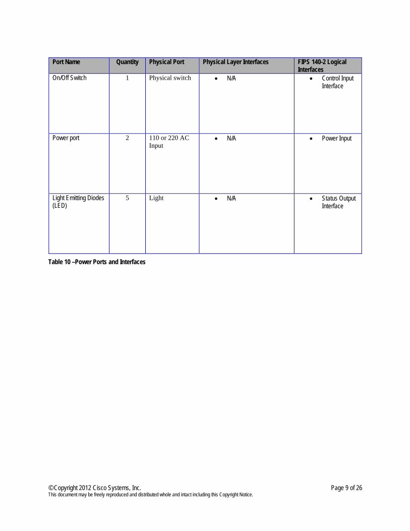
Port Name Quantity Physical Port Physical Layer Interfaces FIPS 140-2 Logical
Interfaces On/Off Switch 1 Physical switch • N/A • Control Input
Interface
Power port 2 110 or 220 AC Input
• N/A • Power Input
Light Emitting Diodes (LED)
5 Light • N/A • Status Output Interface
Table 10 –Power Ports and Interfaces
© Copyright 2012 Cisco Systems, Inc. Page 10 of 26 This document may be freely reproduced and distributed whole and intact including this Copyright Notice.
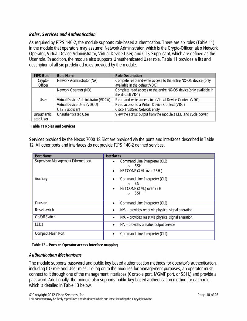
Roles, Services and Authentication As required by FIPS 140-2, the module supports role-based authentication. There are six roles (Table 11) in the module that operators may assume: Network Administrator, which is the Crypto-Officer, also Network Operator, Virtual Device Administrator, Virtual Device User, and CTS Supplicant, which are defined as the User role. In addition, the module also supports Unauthenticated User role. Table 11 provides a list and description of all six predefined roles provided by the module.
FIPS Role Role Name Role Description Crypto-Officer
Network Administrator (NA) Compete read-and-write access to the entire NX-OS device (only available in the default VDC)
User
Network Operator (NO) Complete read access to the entire NX-OS device(only available in the default VDC)
Virtual Device Administrator (VDCA) Read-and-write access to a Virtual Device Context (VDC) Virtual Device User (VDCU) Read access to a Virtual Device Context (VDC) CTS Supplicant Cisco TrustSec Network entity
Unauthenticated User
Unauthenticated User View the status output from the module’s LED and cycle power.
Table 11 Roles and Services
Services provided by the Nexus 7000 18 Slot are provided via the ports and interfaces described in Table 12. All other ports and interfaces do not provide FIPS 140-2 defined services.
Port Name Interfaces Supervisor Management Ethernet port • Command Line Interpreter (CLI)
o SSH • NETCONF (XML over SSH )
Auxiliary • Command Line Interpreter (CLI) o SS
• NETCONF (XML) over SSH o SSH
Console • Command Line Interpreter (CLI) Reset switch • N/A – provides reset via physical signal alteration On/Off Switch • N/A – provides reset via physical signal alteration LEDs • NA – provides a status output service
Compact Flash Port • Command Line Interpreter (CLI)
Table 12 – Ports to Operator access interface mapping
Authentication Mechanisms The module supports password and public key based authentication methods for operator’s authentication, including CO role and User roles. To log on to the modules for management purposes, an operator must connect to it through one of the management interfaces (Console port, MGMT port, or SSH,) and provide a password. Additionally, the module also supports public key based authentication method for each role, which is detailed in Table 13 below.
© Copyright 2012 Cisco Systems, Inc. Page 11 of 26 This document may be freely reproduced and distributed whole and intact including this Copyright Notice.
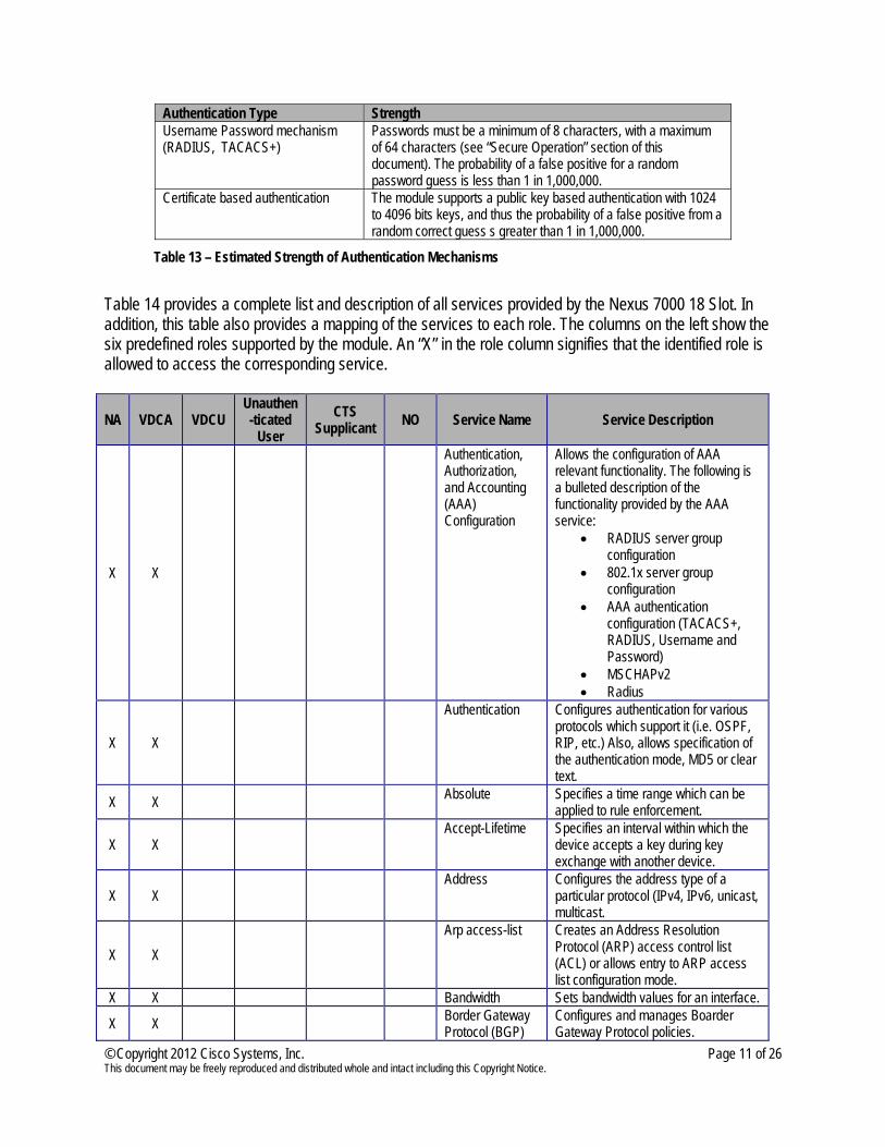
Authentication Type Strength Username Password mechanism (RADIUS, TACACS+)
Passwords must be a minimum of 8 characters, with a maximum of 64 characters (see “Secure Operation” section of this document). The probability of a false positive for a random password guess is less than 1 in 1,000,000.
Certificate based authentication The module supports a public key based authentication with 1024 to 4096 bits keys, and thus the probability of a false positive from a random correct guess s greater than 1 in 1,000,000.
Table 13 – Estimated Strength of Authentication Mechanisms
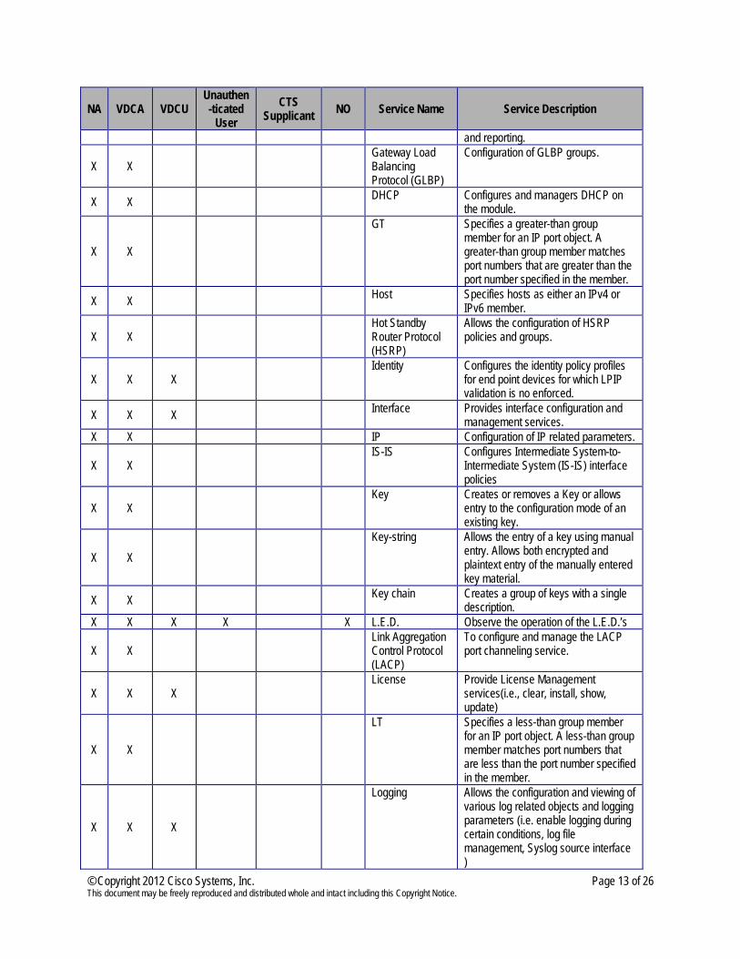
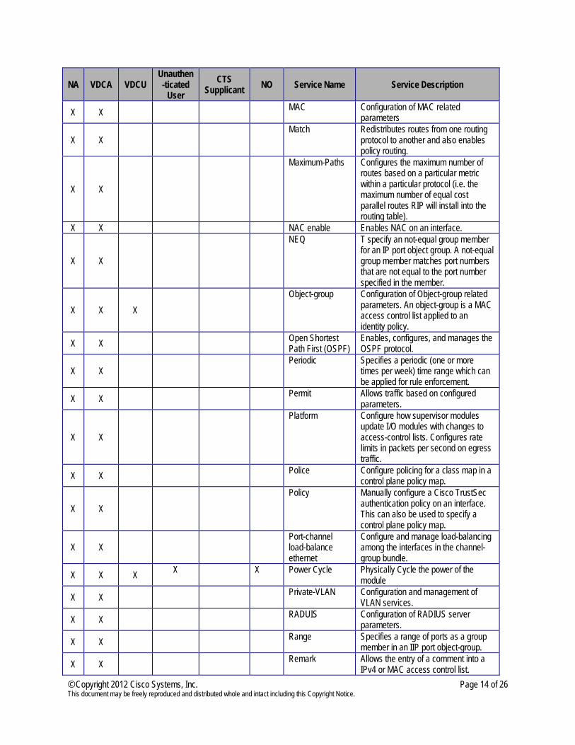
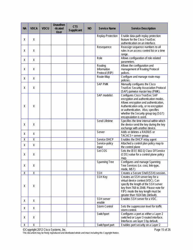
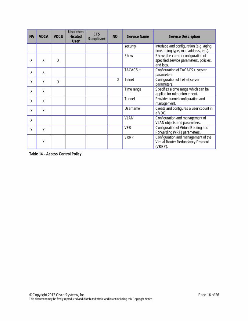
Table 14 provides a complete list and description of all services provided by the Nexus 7000 18 Slot. In addition, this table also provides a mapping of the services to each role. The columns on the left show the six predefined roles supported by the module. An “X” in the role column signifies that the identified role is allowed to access the corresponding service.
NA VDCA VDCU Unauthen-ticated
User CTS
Supplicant NO Service Name Service Description
X X
Authentication, Authorization, and Accounting (AAA) Configuration
Allows the configuration of AAA relevant functionality. The following is a bulleted description of the functionality provided by the AAA service:
• RADIUS server group configuration
• 802.1x server group configuration
• AAA authentication configuration (TACACS+, RADIUS, Username and Password)
• MSCHAPv2 • Radius
X X
Authentication Configures authentication for various protocols which support it (i.e. OSPF, RIP, etc.) Also, allows specification of the authentication mode, MD5 or clear text.
X X Absolute Specifies a time range which can be applied to rule enforcement.
X X Accept-Lifetime Specifies an interval within which the
device accepts a key during key exchange with another device.
X X Address Configures the address type of a
particular protocol (IPv4, IPv6, unicast, multicast.
X X Arp access-list Creates an Address Resolution
Protocol (ARP) access control list (ACL) or allows entry to ARP access list configuration mode.
X X Bandwidth Sets bandwidth values for an interface.
X X Border Gateway Protocol (BGP)
Configures and manages Boarder Gateway Protocol policies.
© Copyright 2012 Cisco Systems, Inc. Page 12 of 26 This document may be freely reproduced and distributed whole and intact including this Copyright Notice.
NA VDCA VDCU Unauthen-ticated
User CTS
Supplicant NO Service Name Service Description
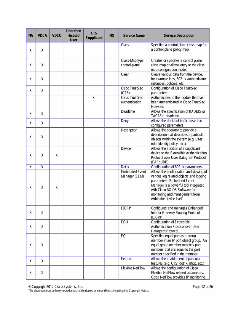
X X Class
Specifies a control plane class map for a control plane policy map.
X X Class-Map type
control-plane Creates or specifies a control plane class map or allows entry to the class map configuration mode.
X X Clear Clears various data from the device,
for example logs, 802.1x authenticator instances, policies, etc.
X X Cisco TrustSec (CTS)
Configuration of Cisco TrustSec parameters.
X Cisco TrustSec
authentication Authenticates to the module that has been authenticated in Cisco TrustSec Network.
X X Deadtime Allows the specification of RADIUS or TACAS+ deadtime
X X Deny Allows the denial of traffic based on configured parameters.
X X Description Allows the operator to provide a
description that describes a particular objects within the system (e.g. User role, identity policy, etc.).
X X X Device Allows the addition of a supplicant
device to the Extensible Authentication Protocol over User Datagram Protocol (EAPoUDP)
X X Dot1x Configuration of 802.1x parameters.
X X X
Embedded Event Manager (EEM)
Allows the configuration and viewing of various log related objects and logging parameters. Embedded Event Manager is a powerful tool integrated with Cisco NX-OS Software for monitoring and management from within the device itself.
X X EIGRP Configures and manages Enhanced
Interior Gateway Routing Protocol (EIGRP)
X X EOU Configuration of Extensible
Authentication Protocol over User Datagram Protocol.
X X
EQ Specifies equal port as a group member in an IP port object group. An equal group member matches port numbers that are equal to the port number specified in the member.
X X Feature Allows the enablement of paticular features (e.g. CTS, dot1x, dhcp, etc.)
X X Flexible NetFlow Allows the configuration of Cisco
Flexible NetFlow related parameters. Cisco NetFlow provides IP monitoring
© Copyright 2012 Cisco Systems, Inc. Page 13 of 26 This document may be freely reproduced and distributed whole and intact including this Copyright Notice.
NA VDCA VDCU Unauthen-ticated
User CTS
Supplicant NO Service Name Service Description
and reporting.
X X Gateway Load
Balancing Protocol (GLBP)
Configuration of GLBP groups.
X X DHCP Configures and managers DHCP on the module.
X X
GT Specifies a greater-than group member for an IP port object. A greater-than group member matches port numbers that are greater than the port number specified in the member.
X X Host Specifies hosts as either an IPv4 or IPv6 member.
X X Hot Standby
Router Protocol (HSRP)
Allows the configuration of HSRP policies and groups.
X X X Identity Configures the identity policy profiles
for end point devices for which LPIP validation is no enforced.
X X X Interface Provides interface configuration and management services.
X X IP Configuration of IP related parameters.
X X IS-IS Configures Intermediate System-to-
Intermediate System (IS-IS) interface policies
X X Key Creates or removes a Key or allows
entry to the configuration mode of an existing key.
X X Key-string Allows the entry of a key using manual
entry. Allows both encrypted and plaintext entry of the manually entered key material.
X X Key chain Creates a group of keys with a single description.
X X X X X L.E.D. Observe the operation of the L.E.D.’s
X X Link Aggregation
Control Protocol (LACP)
To configure and manage the LACP port channeling service.
X X X License Provide License Management
services(i.e., clear, install, show, update)
X X
LT Specifies a less-than group member for an IP port object. A less-than group member matches port numbers that are less than the port number specified in the member.
X X X
Logging Allows the configuration and viewing of various log related objects and logging parameters (i.e. enable logging during certain conditions, log file management, Syslog source interface )
© Copyright 2012 Cisco Systems, Inc. Page 14 of 26 This document may be freely reproduced and distributed whole and intact including this Copyright Notice.
NA VDCA VDCU Unauthen-ticated
User CTS
Supplicant NO Service Name Service Description
X X MAC Configuration of MAC related parameters
X X Match Redistributes routes from one routing
protocol to another and also enables policy routing.
X X
Maximum-Paths Configures the maximum number of routes based on a particular metric within a particular protocol (i.e. the maximum number of equal cost parallel routes RIP will install into the routing table).
X X NAC enable Enables NAC on an interface.
X X
NEQ T specify an not-equal group member for an IP port object group. A not-equal group member matches port numbers that are not equal to the port number specified in the member.
X X X Object-group Configuration of Object-group related
parameters. An object-group is a MAC access control list applied to an identity policy.
X X Open Shortest Path First (OSPF)
Enables, configures, and manages the OSPF protocol.
X X Periodic Specifies a periodic (one or more
times per week) time range which can be applied for rule enforcement.
X X Permit Allows traffic based on configured parameters.
X X
Platform Configure how supervisor modules update I/O modules with changes to access-control lists. Configures rate limits in packets per second on egress traffic.
X X Police Configure policing for a class map in a control plane policy map.
X X Policy Manually configure a Cisco TrustSec
authentication policy on an interface. This can also be used to specify a control plane policy map.
X X Port-channel
load-balance ethernet
Configure and manage load-balancing among the interfaces in the channel-group bundle.
X X X X X Power Cycle Physically Cycle the power of the module
X X Private-VLAN Configuration and management of VLAN services.
X X RADUIS Configuration of RADIUS server parameters.
X X Range Specifies a range of ports as a group member in an IIP port object-group.
X X Remark Allows the entry of a comment into a IPv4 or MAC access control list.
© Copyright 2012 Cisco Systems, Inc. Page 15 of 26 This document may be freely reproduced and distributed whole and intact including this Copyright Notice.
NA VDCA VDCU Unauthen-ticated
User CTS
Supplicant NO Service Name Service Description
X X Replay-Protection Enable data-path replay protection
feature for the Cisco TrustSec authentication on an interface.
X X Resequence Reassign sequence numbers to all
rules in an access control list or a time range.
X X Role Allows configuration of role related parameters.
X X Routing
Information Protocol (RIP)
Allows the configuration and management of Routing Protocol polices.
X X Route-Map Configure and manage route-map policies.
X X SAP PMK Manually configures the Cisco
TrustSec Security Association Protocol (SAP) pairwise master key (PMK).
X X
SAP modelist Configures Cisco TrustSec SAP encryption and authentication modes. Allows encryption and authentication, Authentication only, or no encryption or authentication. Also, specifies whether the Security group tag (SGT) encapsulation is used.
X X Send Lifetime Specifies the time interval within which
the device send the key during the key exchange with another device.
X X Server Adds or deletes a RADIUS or TACACS+ server group.
X X Service DHCP Enables the DHCP relay agent
X X Service-policy input
Attached a control plan policy map to the control plane
X X Set COS Sets the IEEE 802.Q Class Of Service
(COS) value for a control plane policy map.
X X Spanning Tree Configures and manage Spanning
Tree Services (i.e. cost, link-type, mode, MST)
X X SSH Creates a Secure Shell (SSH) session.
X X
SSH Key Creates an SSH server key for a virtual device context (VDC). Can specify the length of the SSH server key from 768 to 2048. Please note for FIPS mode the key length must be greater than 1024 bits (default).
X X SSH server enable
Enables SSH server for a VDC.
X X Storm Control Sets the suppression level for traffic storm control.
X X Switchport Configures a port as either a Layer 2
switched or Layer 3 routed interface. Interfaces are layer 3 by default.
X X Switchport port Enables port security on a Layer 2
© Copyright 2012 Cisco Systems, Inc. Page 16 of 26 This document may be freely reproduced and distributed whole and intact including this Copyright Notice.
NA VDCA VDCU Unauthen-ticated
User CTS
Supplicant NO Service Name Service Description
security interface and configuration (e.g. aging time, aging type, mac address, etc.).
X X X Show Shows the current configuration of
specified service parameters, policies, and logs.
X X TACACS + Configuration of TACACS+ server parameters.
X X X X Telnet Configuration of Telnet server parameters.
X X Time range Specifies a time range which can be applied for rule enforcement.
X X Tunnel Provides tunnel configuration and management.
X X Username Creats and configures a user ccount in a VDC.
X VLAN Configuration and management of VLAN objects and parameters.
X X VFR Configuration of Virtual Routing and Forwarding (VRF) parameters.
X VRRP Configuration and management of the
Virtual Router Redundancy Protocol (VRRP).
Table 14 – Access Control Policy
© Copyright 2008 Cisco Systems, Inc. Page 17 of 26 This document may be freely reproduced and distributed whole and intact including this Copyright Notice.
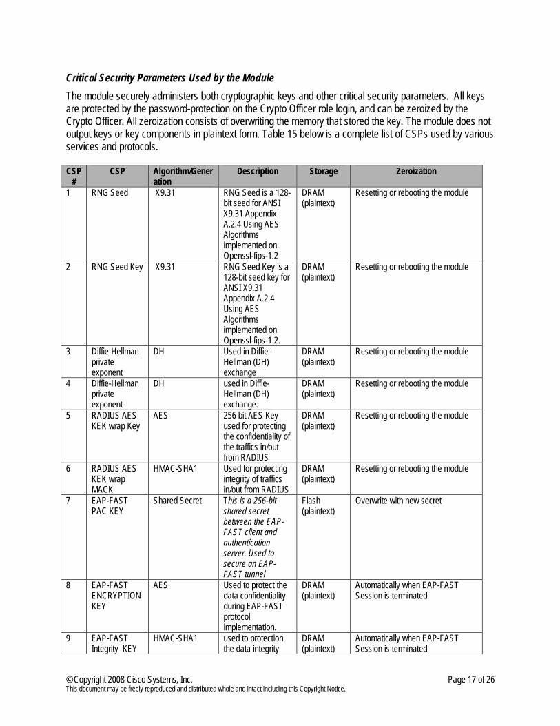
Critical Security Parameters Used by the Module The module securely administers both cryptographic keys and other critical security parameters. All keys are protected by the password-protection on the Crypto Officer role login, and can be zeroized by the Crypto Officer. All zeroization consists of overwriting the memory that stored the key. The module does not output keys or key components in plaintext form. Table 15 below is a complete list of CSPs used by various services and protocols. CSP
# CSP Algorithm/Gener
ation Description Storage Zeroization
1 RNG Seed X9.31 RNG Seed is a 128-bit seed for ANSI X9.31 Appendix A.2.4 Using AES Algorithms implemented on Openssl-fips-1.2
DRAM (plaintext)
Resetting or rebooting the module
2 RNG Seed Key X9.31 RNG Seed Key is a 128-bit seed key for ANSI X9.31 Appendix A.2.4 Using AES Algorithms implemented on Openssl-fips-1.2.
DRAM (plaintext)
Resetting or rebooting the module
3 Diffie-Hellman private exponent
DH Used in Diffie-Hellman (DH) exchange
DRAM (plaintext)
Resetting or rebooting the module
4 Diffie-Hellman private exponent
DH used in Diffie-Hellman (DH) exchange.
DRAM (plaintext)
Resetting or rebooting the module
5 RADIUS AES KEK wrap Key
AES 256 bit AES Key used for protecting the confidentiality of the traffics in/out from RADIUS
DRAM (plaintext)
Resetting or rebooting the module
6 RADIUS AES KEK wrap MACK
HMAC-SHA1 Used for protecting integrity of traffics in/out from RADIUS
DRAM (plaintext)
Resetting or rebooting the module
7 EAP-FAST PAC KEY
Shared Secret This is a 256-bit shared secret between the EAP-FAST client and authentication server. Used to secure an EAP-FAST tunnel
Flash (plaintext)
Overwrite with new secret
8 EAP-FAST ENCRYPTION KEY
AES Used to protect the data confidentiality during EAP-FAST protocol implementation.
DRAM (plaintext)
Automatically when EAP-FAST Session is terminated
9 EAP-FAST Integrity KEY
HMAC-SHA1 used to protection the data integrity
DRAM (plaintext)
Automatically when EAP-FAST Session is terminated
© Copyright 2011 Cisco Systems, Inc. Page 18 of 26 This document may be freely reproduced and distributed whole and intact including this Copyright Notice.
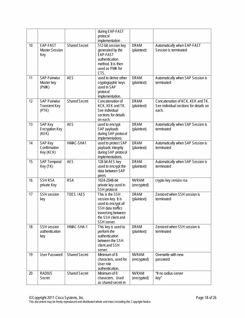
during EAP-FAST protocol implementation
10 EAP-FAST Master Session Key
Shared Secret 512-bit session key generated by the EAP-FAST authentication method. It is then used as PMK for CTS.
DRAM (plaintext)
Automatically when EAP-FAST Session is terminated
11 SAP Pairwise Master key (PMK)
AES used to derive other cryptographic keys used in SAP protocol implementation.
DRAM (plaintext)
Automatically when SAP Session is terminated
12 SAP Pairwise Transient Key (PTK)
Shared Secret Concatenation of KCK, KEK and TK. See individual sections for details on each.
DRAM (plaintext)
Concatenation of KCK, KEK and TK. See individual sections for details on each.
13 SAP Key Encryption Key (KEK)
AES used to encrypt SAP payloads during SAP protocol implementations.
DRAM (plaintext)
Automatically when SAP Session is terminated
14 SAP Key Confirmation Key (KCK)
HMAC-SHA1 used to protect SAP payloads integrity during SAP protocol implementations.
DRAM (plaintext)
Automatically when SAP Session is terminated
15 SAP Temporal Key (TK)
AES 128 bit AES key used to encrypt the data between SAP peers
DRAM (plaintext)
Automatically when SAP Session is terminated
16 SSH RSA private Key
RSA 1024-2048-bit private key used in SSH protocol
NVRAM (encrypted)
crypto key zeroize rsa
17 SSH session key
TDES / AES This is the SSH session key. It is used to encrypt all SSH data traffics traversing between the SSH client and SSH server.
DRAM (plaintext)
Zeroized when SSH session is terminated
18 SSH session authentication key
HMAC-SHA-1 This key is used to perform the authentication between the SSH client and SSH server.
DRAM (plaintext)
Zeroized when SSH session is terminated
19 User Password Shared Secret Minimum of 8 characters, used for User role authentication.
NVRAM (encrypted)
Overwrite with new password
20 RADIUS Secret
Shared Secret Minimum of 8 characters. Used as shared secret in
NVRAM (encrypted)
“# no radius-server key”
© Copyright 2011 Cisco Systems, Inc. Page 19 of 26 This document may be freely reproduced and distributed whole and intact including this Copyright Notice.
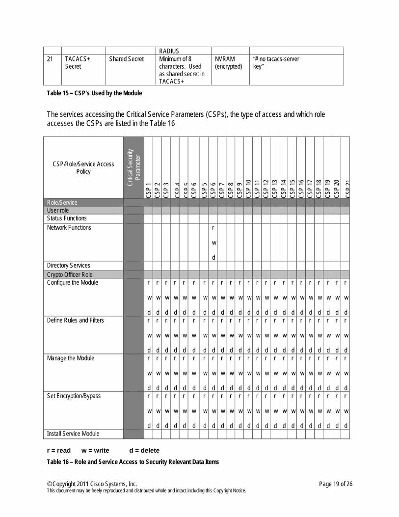
RADIUS 21 TACACS+
Secret Shared Secret Minimum of 8
characters. Used as shared secret in TACACS+
NVRAM (encrypted)
“# no tacacs-server key”
Table 15 – CSP’s Used by the Module
The services accessing the Critical Service Parameters (CSPs), the type of access and which role accesses the CSPs are listed in the Table 16
CSP/Role/Service Access Policy
Critic
al Se
curity
Pa
rame
ter
CSP
1 CS
P 2
CSP
3
CSP
4 CS
P 5
CSP
6 CS
P 5
CSP
6 CS
P 7
CSP
8 CS
P 9
CSP
10
CSP
11
CSP
12
CSP
13
CSP
14
CSP
15
CSP
16
CSP
17
CSP
18
CSP
19
CSP
20
CSP
21
Role/Service User role Status Functions Network Functions r
w d
Directory Services Crypto Officer Role Configure the Module r
w d
r w d
r w d
r w d
r w d
r
w d
r w d
r w d
r w d
r w d
r w d
r w d
r w d
r w d
r w d
r w d
r w d
r w d
r w d
r w d
r w d
r w d
r w d
Define Rules and Filters r w d
r w d
r w d
r w d
r w d
r
w d
r w d
r w d
r w d
r w d
r w d
r w d
r w d
r w d
r w d
r w d
r w d
r w d
r w d
r w d
r w d
r w d
r w d
Manage the Module r w d
r w d
r w d
r w d
r w d
r
w d
r w d
r w d
r w d
r w d
r w d
r w d
r w d
r w d
r w d
r w d
r w d
r w d
r w d
r w d
r w d
r w d
r w d
Set Encryption/Bypass r w d
r w d
r w d
r w d
r w d
r
w d
r w d
r w d
r w d
r w d
r w d
r w d
r w d
r w d
r w d
r w d
r w d
r w d
r w d
r w d
r w d
r w d
r w d
Install Service Module r = read w = write d = delete
Table 16 – Role and Service Access to Security Relevant Data Items
© Copyright 2011 Cisco Systems, Inc. Page 20 of 26 This document may be freely reproduced and distributed whole and intact including this Copyright Notice.
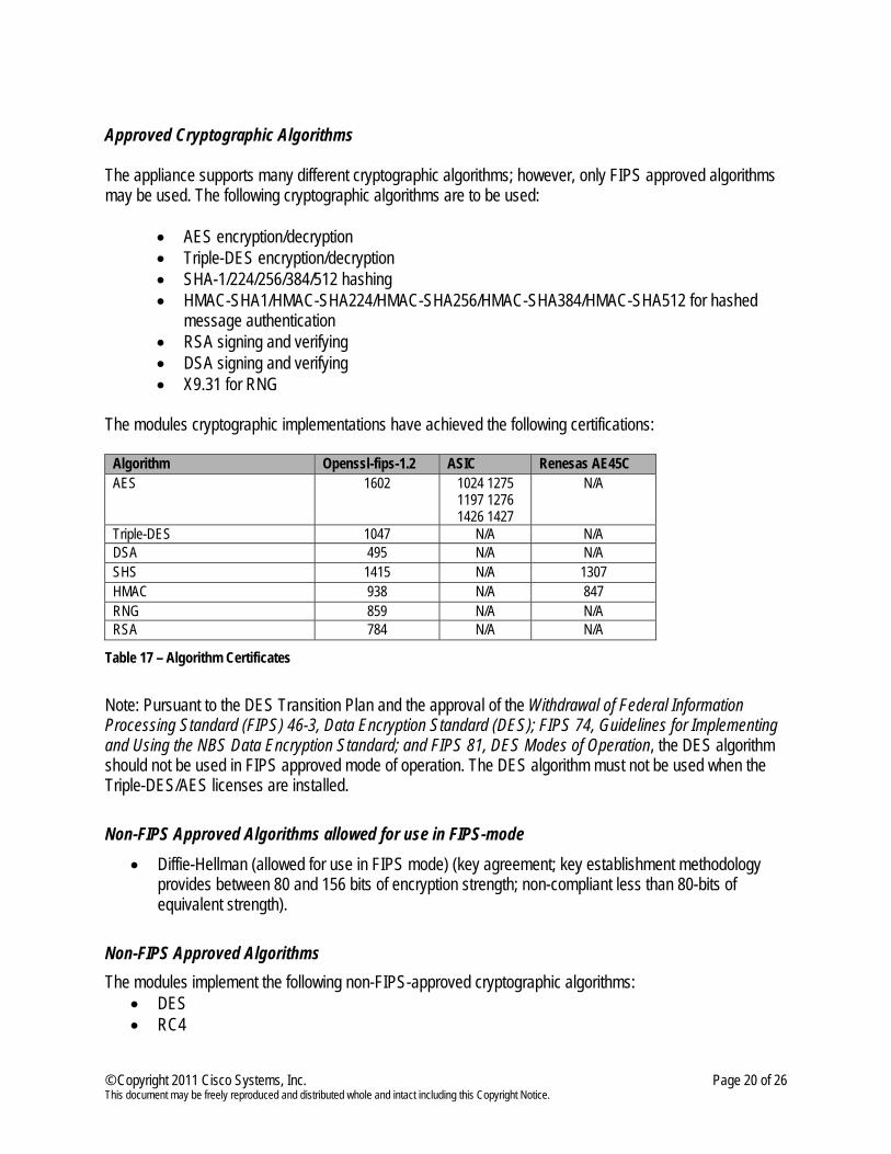
Approved Cryptographic Algorithms The appliance supports many different cryptographic algorithms; however, only FIPS approved algorithms may be used. The following cryptographic algorithms are to be used:
• AES encryption/decryption • Triple-DES encryption/decryption • SHA-1/224/256/384/512 hashing • HMAC-SHA1/HMAC-SHA224/HMAC-SHA256/HMAC-SHA384/HMAC-SHA512 for hashed
message authentication • RSA signing and verifying • DSA signing and verifying • X9.31 for RNG
The modules cryptographic implementations have achieved the following certifications:
Algorithm Openssl-fips-1.2 ASIC Renesas AE45C AES 1602 1024 1275
1197 1276 1426 1427
N/A
Triple-DES 1047 N/A N/A DSA 495 N/A N/A SHS 1415 N/A 1307 HMAC 938 N/A 847 RNG 859 N/A N/A RSA 784 N/A N/A
Table 17 – Algorithm Certificates
Note: Pursuant to the DES Transition Plan and the approval of the Withdrawal of Federal Information Processing Standard (FIPS) 46-3, Data Encryption Standard (DES); FIPS 74, Guidelines for Implementing and Using the NBS Data Encryption Standard; and FIPS 81, DES Modes of Operation, the DES algorithm should not be used in FIPS approved mode of operation. The DES algorithm must not be used when the Triple-DES/AES licenses are installed. Non-FIPS Approved Algorithms allowed for use in FIPS-mode
• Diffie-Hellman (allowed for use in FIPS mode) (key agreement; key establishment methodology provides between 80 and 156 bits of encryption strength; non-compliant less than 80-bits of equivalent strength).
Non-FIPS Approved Algorithms The modules implement the following non-FIPS-approved cryptographic algorithms:
• DES • RC4
© Copyright 2011 Cisco Systems, Inc. Page 21 of 26 This document may be freely reproduced and distributed whole and intact including this Copyright Notice.
• MD5 • MD5 HMAC • Non-Approved RNG
Note: Non-FIPS approved algorithms cannot be used in FIPS mode of operation.
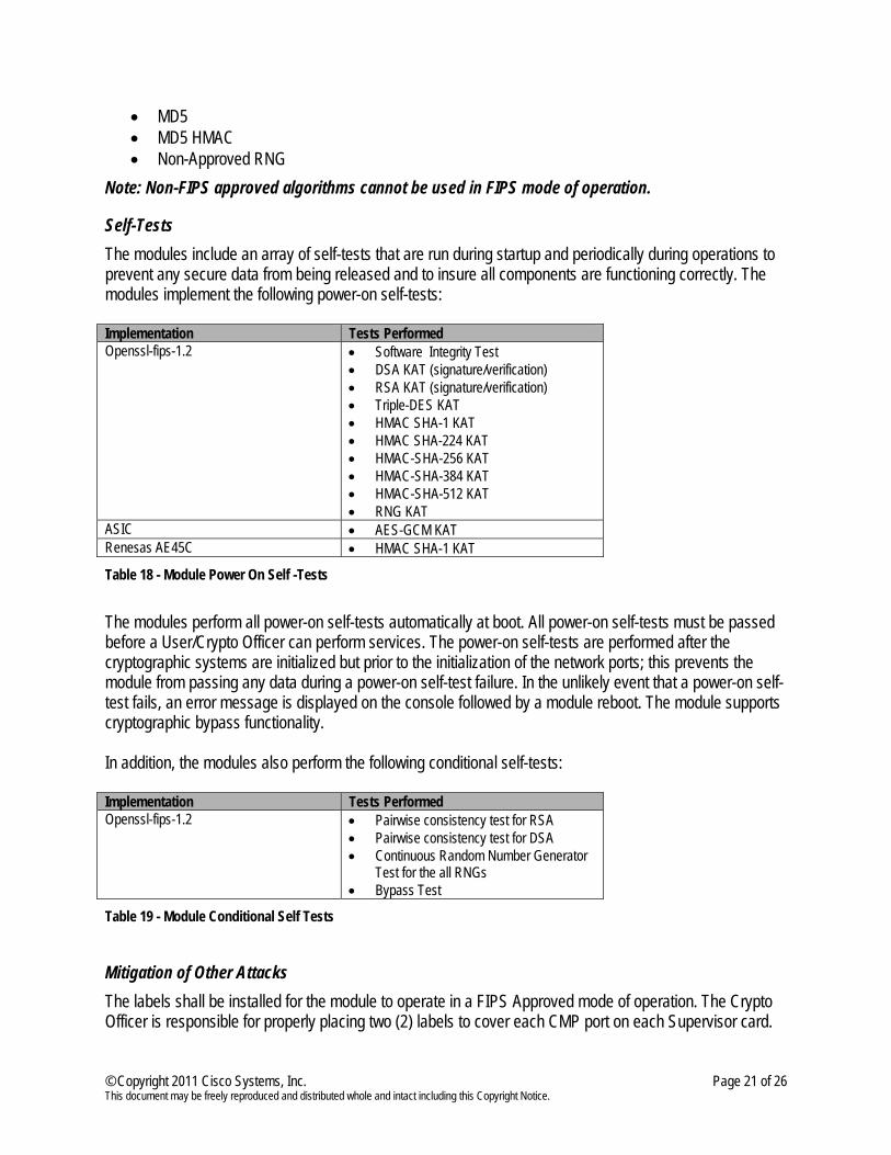
Self-Tests The modules include an array of self-tests that are run during startup and periodically during operations to prevent any secure data from being released and to insure all components are functioning correctly. The modules implement the following power-on self-tests: Implementation Tests Performed Openssl-fips-1.2 • Software Integrity Test
• DSA KAT (signature/verification) • RSA KAT (signature/verification) • Triple-DES KAT • HMAC SHA-1 KAT • HMAC SHA-224 KAT • HMAC-SHA-256 KAT • HMAC-SHA-384 KAT • HMAC-SHA-512 KAT • RNG KAT
ASIC • AES-GCM KAT Renesas AE45C • HMAC SHA-1 KAT
Table 18 - Module Power On Self -Tests
The modules perform all power-on self-tests automatically at boot. All power-on self-tests must be passed before a User/Crypto Officer can perform services. The power-on self-tests are performed after the cryptographic systems are initialized but prior to the initialization of the network ports; this prevents the module from passing any data during a power-on self-test failure. In the unlikely event that a power-on self-test fails, an error message is displayed on the console followed by a module reboot. The module supports cryptographic bypass functionality. In addition, the modules also perform the following conditional self-tests: Implementation Tests Performed Openssl-fips-1.2 • Pairwise consistency test for RSA
• Pairwise consistency test for DSA • Continuous Random Number Generator
Test for the all RNGs • Bypass Test
Table 19 - Module Conditional Self Tests
Mitigation of Other Attacks The labels shall be installed for the module to operate in a FIPS Approved mode of operation. The Crypto Officer is responsible for properly placing two (2) labels to cover each CMP port on each Supervisor card.
© Copyright 2011 Cisco Systems, Inc. Page 22 of 26 This document may be freely reproduced and distributed whole and intact including this Copyright Notice.
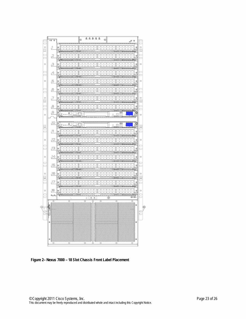
The labels recommended for FIPS 140-2 compliance are provided in the FIPS Kit (Cisco-FIPS-KIT=). These labels are very fragile and cannot be removed without clear signs of damage to the labels. The Crypto Officer should inspect the labels periodically to verify they are intact and the serial numbers on the applied labels match the records in the security log. Application of the serialized labels is as follows: Nexus 7000 – 18 Slot Chassis 1. Turn off and unplug the system before cleaning the chassis and applying labels.
2. For each supervisor module installed, place a label to cover Connectivity Management Processor port
(CMP) port. 3. Record the serial numbers of the labels applied to the system in a security log.
© Copyright 2011 Cisco Systems, Inc. Page 23 of 26 This document may be freely reproduced and distributed whole and intact including this Copyright Notice.
Figure 2– Nexus 7000 – 18 Slot Chassis Front Label Placement
© Copyright 2011 Cisco Systems, Inc. Page 24 of 26 This document may be freely reproduced and distributed whole and intact including this Copyright Notice.
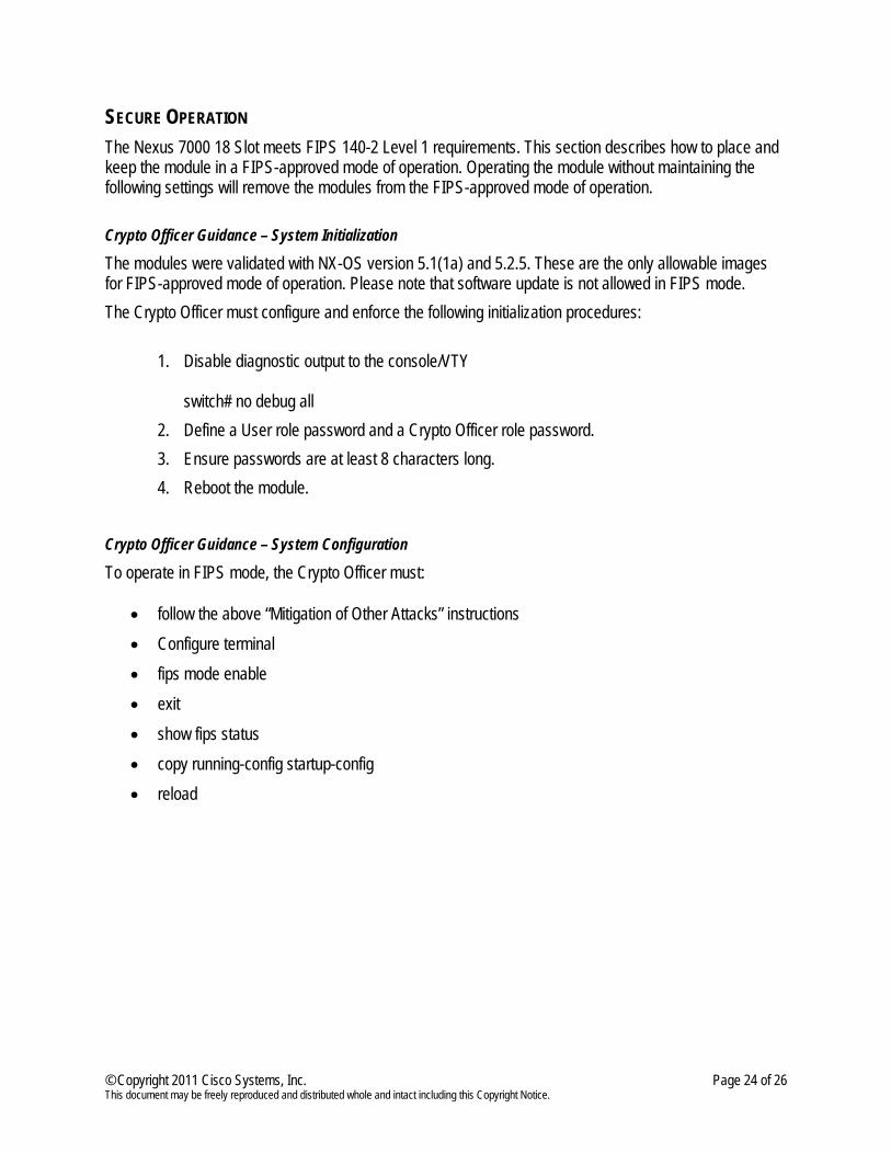
SECURE OPERATION The Nexus 7000 18 Slot meets FIPS 140-2 Level 1 requirements. This section describes how to place and keep the module in a FIPS-approved mode of operation. Operating the module without maintaining the following settings will remove the modules from the FIPS-approved mode of operation. Crypto Officer Guidance – System Initialization
The modules were validated with NX-OS version 5.1(1a) and 5.2.5. These are the only allowable images for FIPS-approved mode of operation. Please note that software update is not allowed in FIPS mode. The Crypto Officer must configure and enforce the following initialization procedures:
1. Disable diagnostic output to the console/VTY switch# no debug all
2. Define a User role password and a Crypto Officer role password. 3. Ensure passwords are at least 8 characters long. 4. Reboot the module.
Crypto Officer Guidance – System Configuration
To operate in FIPS mode, the Crypto Officer must:
• follow the above “Mitigation of Other Attacks” instructions • Configure terminal • fips mode enable • exit • show fips status • copy running-config startup-config • reload
© Copyright 2011 Cisco Systems, Inc. Page 25 of 26 This document may be freely reproduced and distributed whole and intact including this Copyright Notice.
Identifying Operation in an Approved Mode The following activities are required to verify that that the module is operating in an Approved mode of operation. 1. Verify that the labels have been properly placed on the module based on the instructions specified in
the “Mitigation of Other Attacks” section of this document
2. Verify that the length of User and Crypto Officer passwords and all shared secrets are at least eight (8) characters long, as specified in the “Crypto Officer Guidance – System Initialization” section of this document.
3. Issue the command: ‘show fips status’ and verify that “FIPS status is enabled” is shown on Command Line Interface.
© Copyright 2011 Cisco Systems, Inc. Page 26 of 26 This document may be freely reproduced and distributed whole and intact including this Copyright Notice.
DEFINITION LIST AES Advanced Encryption Standard AT Abbreviation for Authenticators (see Authenticators) Authenticators Devices that are already part of a Cisco TrustSec network COS Class of Service CMVP Cryptographic Module Validation Program CSP Critical Security Parameter CTS Cisco TrustSec protocol DES Data Encryption Standard EAP Extensible Authentication Protocol FIPS Federal Information Processing Standard HTTP Hyper Text Transfer Protocol KAT Known Answer Test LAN Local Area Network LED Light Emitting Diode LPIP LAN Port IP Traffic MST Multiple Spanning Tree NA Network Administrator NAC Network Admission Control NIST National Institute of Standards and Technology NO Network Operator NVLAP National Voluntary Laboratory Accreditation Program PMK Pairwise Master Key PPP Point-to-Point Protocol RAM Random Access Memory RSA Rivest Shamir and Adleman method for asymmetric encryption SAN Storage Area Network SGT Security group tag SAP Security Association Protocol SHA Secure Hash Algorithm SSH Secure Shell SSL Secure Sockets Layer SM Service Module Supplicants Devices that attempt to join a Cisco TrustSec network. TLS Transport Layer Security VDC Virtual Device Control VDCA Virtual Device Administrator VDCU Virtual Device User VLAN Virtual LAN VRF Virtual Routing and Forwarding