Embed Size (px)
Citation preview
56 september 2006 www.pump-zone.com pumps & systems
Next Steps in . . . Vibration + Alignment
In this work, bearing vibration and reaction force signa-tures caused by bent shafts were studied experimentally.
The vibration and force spectrum signatures between baseline and bent shafts (center bent and coupling end bent) under two shaft speeds, 1000-rpm and 5000-rpm, were compared. The bearing reaction force associated with a center bent shaft under different shaft speeds were calculated by subtracting the baseline reaction force from the total reac-tion force.
The experiment results indicate that for low shaft speed (1000-rpm), the effect of bent shaft on bearing vibration can be neglected. Under high speed (5000-rpm), a center bent shaft will increase the bearing vibration. However, a center bent shaft will increase bearing reaction force for both low and high speeds. The effect of a coupling end shaft on bear-ing vibration and reaction force is not conclusive. Finally, the bearing reaction force is not affected by the shaft speed significantly.
Test Setup The tests were carried out on our own machinery fault simu-lator™ (MFS). By using such a simulator, one can design different kinds of intentional faults and conduct various experiments on rotating machinery diagnostics.
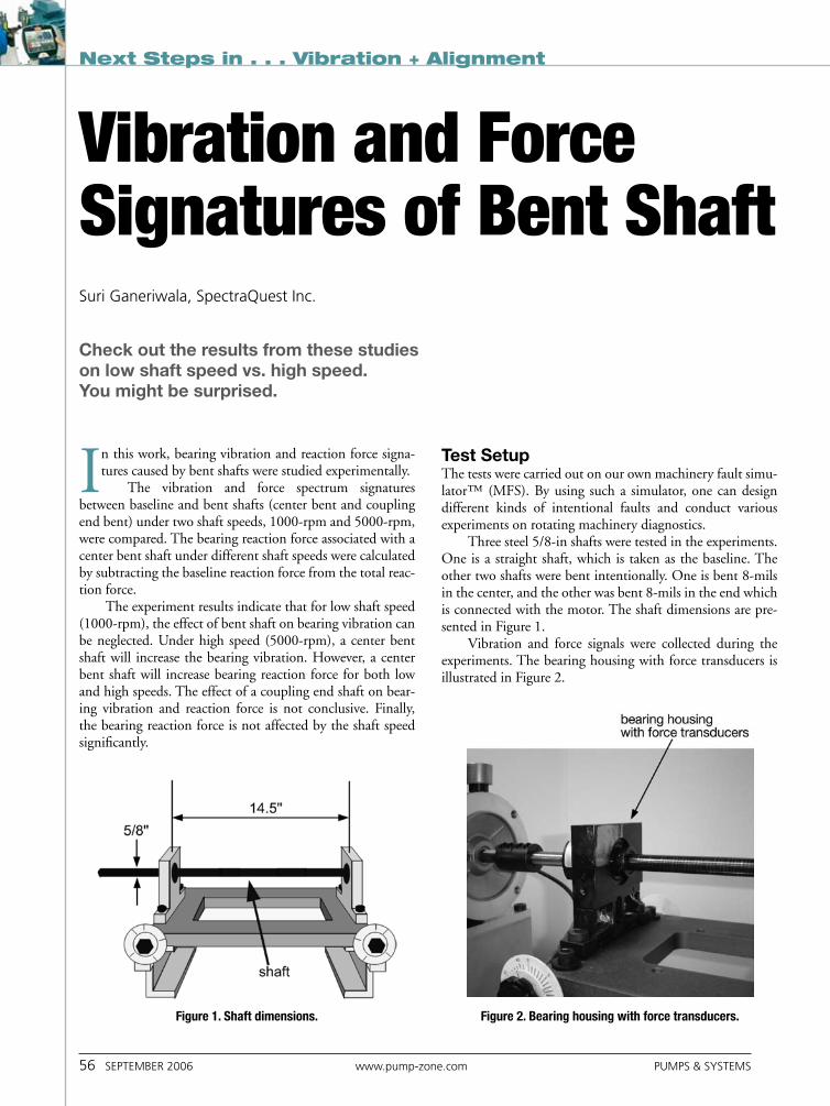
Three steel 5/8-in shafts were tested in the experiments. One is a straight shaft, which is taken as the baseline. The other two shafts were bent intentionally. One is bent 8-mils in the center, and the other was bent 8-mils in the end which is connected with the motor. The shaft dimensions are pre-sented in Figure 1.
Vibration and force signals were collected during the experiments. The bearing housing with force transducers is illustrated in Figure 2.
Vibration and Force Signatures of Bent Shaftsuri Ganeriwala, spectraQuest Inc.
Check out the results from these studies on low shaft speed vs. high speed. You might be surprised.
Figure 1. Shaft dimensions. Figure 2. Bearing housing with force transducers.
pumps & systems www.pump-zone.com september 2006 57
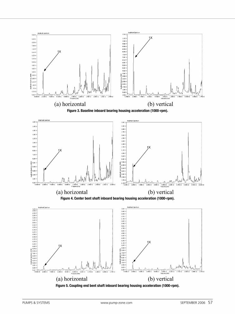
Figure 3. Baseline inboard bearing housing acceleration (1000-rpm).
Figure 4. Center bent shaft inboard bearing housing acceleration (1000-rpm).
Figure 5. Coupling end bent shaft inboard bearing housing acceleration (1000-rpm).
58 september 2006 www.pump-zone.com pumps & systems
Next Steps in . . . Vibration + Alignment
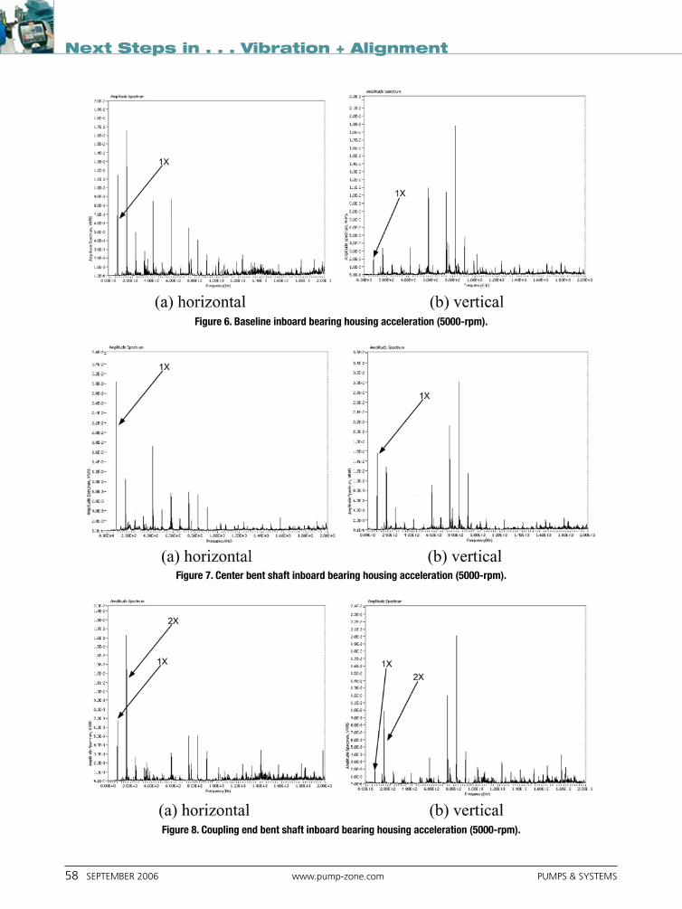
Figure 7. Center bent shaft inboard bearing housing acceleration (5000-rpm).
Figure 8. Coupling end bent shaft inboard bearing housing acceleration (5000-rpm).
Figure 6. Baseline inboard bearing housing acceleration (5000-rpm).
pumps & systems www.pump-zone.com september 2006 59
The experiments can be divided into two stages. In the first stage, the focus is to compare the vibration and force spectrum signatures between baseline and bent shafts (center bent and coupling end bent) under two shaft speeds, 1000-rpm and 5000-rpm.
In the second stage, the focus is to observe the bearing reaction force associated with a center bent shaft under different shaft speeds. The shaft speed was increased from 500-rpm to 5000-rpm with 500-rpm increments, and the bearing housing forces were collected for each speed.
Results and Discussions The experiment results are presented here, with some discussions.
Baseline vs. Bent ShaftIt was observed that in general, both the bearing reaction force and bearing vibra-tion increase with shaft speed. However, the increase in the bearing reaction force is much smaller than the increase in the bearing vibration. There is one order differ-ence under certain conditions. This difference is associated with the system dynamic stiffness.
Acceleration. The baseline vibration spectrums with 1000-rpm shaft speed are presented in Figure 3. Figure 3 (a) and (b) are the accelerations on the inboard bear-ing housing in the horizontal and vertical directions, respectively. The spectrum is presented in the 200-Hz frequency range. The ‘1X’ vibration component is illus-trated in Figure 3.
The center bent and coupling end bent shaft vibration data are displayed in Figures 4 and 5, respectively.
A careful inspection of Figures 3, 4 and 5 indicates that ‘1X’ component has the highest peak among the first several ‘1X’ harmonics. However, it is not the highest peak in the 200-Hz frequency range displayed. It seems that the bent shaft
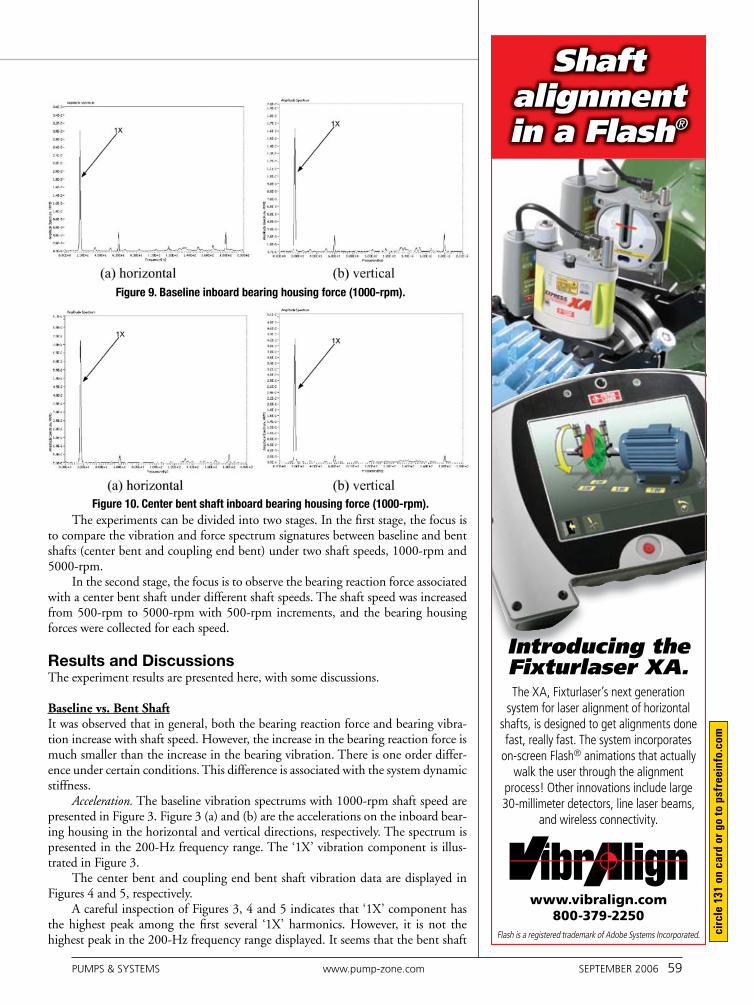
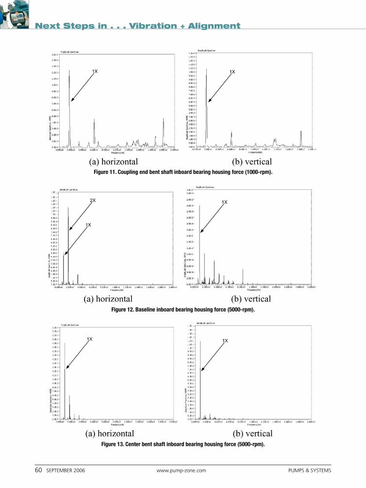
Figure 9. Baseline inboard bearing housing force (1000-rpm).
Figure 10. Center bent shaft inboard bearing housing force (1000-rpm).
www.vibralign.com800-379-2250
Flash is a registered trademark of Adobe Systems Incorporated.
Shaft alignment in a Flash®
Introducing the Fixturlaser XA.The XA, Fixturlaser’s next generation
system for laser alignment of horizontal shafts, is designed to get alignments done fast, really fast. The system incorporates
on-screen Flash® animations that actually walk the user through the alignment
process! Other innovations include large 30-millimeter detectors, line laser beams,
and wireless connectivity.
circ
le 1
31 o
n ca
rd o
r go
to p
sfre
einf
o.co
m
60 september 2006 www.pump-zone.com pumps & systems
Next Steps in . . . Vibration + Alignment
Figure 11. Coupling end bent shaft inboard bearing housing force (1000-rpm).
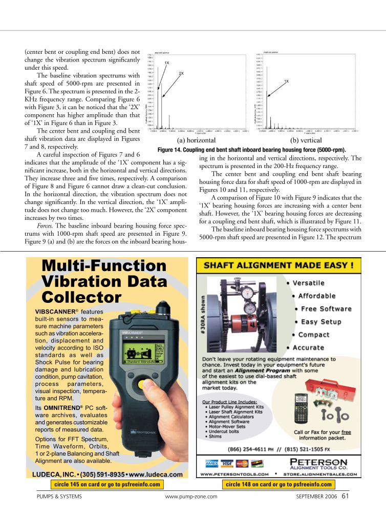
Figure 12. Baseline inboard bearing housing force (5000-rpm).
Figure 13. Center bent shaft inboard bearing housing force (5000-rpm).
pumps & systems www.pump-zone.com september 2006 61
(center bent or coupling end bent) does not change the vibration spectrum significantly under this speed.
The baseline vibration spectrums with shaft speed of 5000-rpm are presented in Figure 6. The spectrum is presented in the 2-KHz frequency range. Comparing Figure 6 with Figure 3, it can be noticed that the ‘2X’ component has higher amplitude than that of ‘1X’ in Figure 6 than in Figure 3.
The center bent and coupling end bent shaft vibration data are displayed in Figures 7 and 8, respectively.
A careful inspection of Figures 7 and 6 indicates that the amplitude of the ‘1X’ component has a sig-nificant increase, both in the horizontal and vertical directions. They increase three and five times, respectively. A comparison of Figure 8 and Figure 6 cannot draw a clean-cut conclusion. In the horizontal direction, the vibration spectrum does not change significantly. In the vertical direction, the ‘1X’ ampli-tude does not change too much. However, the ‘2X’ component increases by two times.
Forces. The baseline inboard bearing housing force spec-trums with 1000-rpm shaft speed are presented in Figure 9. Figure 9 (a) and (b) are the forces on the inboard bearing hous-
ing in the horizontal and vertical directions, respectively. The spectrum is presented in the 200-Hz frequency range.
The center bent and coupling end bent shaft bearing housing force data for shaft speed of 1000-rpm are displayed in Figures 10 and 11, respectively.
A comparison of Figure 10 with Figure 9 indicates that the ‘1X’ bearing housing forces are increasing with a center bent shaft. However, the ‘1X’ bearing housing forces are decreasing for a coupling end bent shaft, which is illustrated by Figure 11.
The baseline inboard bearing housing force spectrums with 5000-rpm shaft speed are presented in Figure 12. The spectrum
Figure 14. Coupling end bent shaft inboard bearing housing force (5000-rpm).
circle 145 on card or go to psfreeinfo.com circle 148 on card or go to psfreeinfo.com

62 september 2006 www.pump-zone.com pumps & systems
Next Steps in . . . Vibration + Alignment
is presented in the 2-KHz frequency range. From Figure 12, it can be noticed that ‘2X’ has higher amplitude than ‘1X’ in the horizontal direction, while the contrary is true in the vertical direction.
The center bent and coupling end bent shaft bearing housing force data for shaft speed of 5000-rpm are displayed in Figures 13 and 14, respectively.
A comparison of Figure 13 with Figure 12 indicates that the ‘1X’ bearing housing forces are increasing with a center bent shaft. Figure 14 illustrates that the ‘1X’ bearing housing forces are also increasing for a coupling end bent shaft.
Bearing Housing Force vs. Shaft Speed The bearing housing force in the horizontal direction vs. shaft speed for the baseline shaft is presented in Figure 15. The three curves rep-resent a pure shaft without any disks installed on it, a shaft with one disk installed at the middle span of the shaft, and a shaft with a disk as well as an unbalance screw on the disk. The RMS values of the force waveform are calculated for each shaft speed condition.
It can be noticed from Figure 15 that the unbalanced ‘curve’ has the shape of a parabolic curve. The force that corresponds to ‘no disk’ and ‘one disk’ also increases with speed. However, it increases only at a later time when the shaft speed is high enough.
The bearing housing force in the horizontal direction vs. shaft speed for the center bent shaft is presented in Figure 16. The overall trend of these three ‘curves’ is increasing with speed. However, the biggest force increase happens for the shaft with a disk (not with a disk as well as an unbalance screw).
To eliminate the effect of disk and unbalance screw on the bent shaft and obtain the force associated with bent shaft, the baseline force were subtracted from the bent shaft force and the differences are presented in Figure 17. Considering the force RMS value range of minus 1.5 and 1.5, it can be argued that the force associated with center bent shaft alone is not affected by shaft speed.
SummaryIn this work, bearing vibration and reaction force signatures caused by bent shafts were studied experimentally on a machinery fault sim-ulatorTM (MFS).
The vibration and force spectrum signatures between baseline and bent shafts (center bent and coupling end bent) under two shaft speeds, 1000-rpm and 5000-rpm, were compared. The bearing reac-tion force associated with a center bent shaft under different shaft speeds were calculated by subtracting the baseline reaction force from the total reaction force.
The experiment results indicate that for low shaft speed (1000-rpm), the effect of bent shaft on bearing vibration can be neglected. Under high speed (5000-rpm), a center bent shaft will increase ‘1X’ the bearing vibration. However, a center bent shaft will increase ‘1X’ bearing reaction force for both low and high speeds. The effect of a coupling end shaft on bearing vibration and reaction force is not conclusive.
Finally, the bearing reaction force RMS value is not affected by the shaft speed significantly.
P&S
Suri Ganeriwala, PhD, is the president of SpectraQuest Inc., 8205 Hermitage Road, Richmond, VA 23228, 804-261-3300, www.spectraquest.com.
Figure 15. Baseline bearing housing force in horizontal direction.
Figure 16. Total bearing housing force of a center bent shaft in horizontal direction.
Figure 17. Bearing housing force associated with a center bent shaft in horizontal direction.