Embed Size (px)
Citation preview

© MAHLE
Hugh Blaxill, PI
Michael Bunce, Presenter
MAHLE Powertrain, LLC
6/12/2015
Project ID: ACE087
Next-Generation Ultra Lean Burn Powertrain DE-EE0005656
This presentation does not contain any proprietary, confidential, or otherwise restricted information 1
MAHLE Powertrain LLC
Overview
© MAHLE
Project Outline
Timeline Start Date: February 1, 2012
End Date: June 30, 2015
Percent Complete: 85%
Project Goals/ACE Barriers Addressed 45% thermal efficiency on a light duty SI engine
with emissions comparable to or below existing SI engines (A, B, C, D, F)
30% predicted drive cycle fuel economy improvement over comparable gasoline engine vehicle (A, C, H)
Cost effective system requiring minimal modification to existing hardware (G)
Budget
Contract Value (80/20): $ 3,172,779 Gov’t Share: $ 2,499,993 MPT Share: $ 672,796
Funding received in FY2014: $ 940,450
Funding for FY2015: $ 124,203
Partners & Subcontractors
Test engine platform
Custom injector design and development
2

MAHLE Powertrain LLC
Relevance
© MAHLE
Background
Demand for highly efficient and clean engines
– Lean operation increases efficiency but typically results in higher NOx
– Ultra lean operation (λ>2) has been shown to increase efficiency and reduce NOx due to low cylinder temperatures
Turbulent Jet Ignition (TJI) is a pre-chamber-based combustion system offers distributed ignition from fast moving jets of burned/burning products enabling ultra lean operation
– Low NOx
– Increased knock resistance at high loads
– Integration into production hardware
Enabling technologies
– TJI + Boosting
3
Nozzle with orifices
Main chamber PFI (~97% total fuel
energy)
Pre-chamber DI (up to ~3% total
fuel energy)

MAHLE Powertrain LLC
Relevance
4 © MAHLE
Turbulent Jet Ignition Overview
Auxiliary fueling event enables effective decoupling of pre/main chamber air-fuel ratios
Thermal efficiency benefit of TJI
– Ultra-lean operation
– Reduced throttling losses
– Reduced knock @ HL
Boosting can enable map-wide lean/ultra-lean operation
– Multiple operating strategies/platforms
Speed: 1500 rpm IMEPg 3.8 bar λ = 1.2
p/c injection event (>60 dBTDC)
spark timing
mass transfer from p/c to m/c =
jet formation
MAHLE Powertrain LLC
Relevance
© MAHLE
Objectives/ACE Barriers
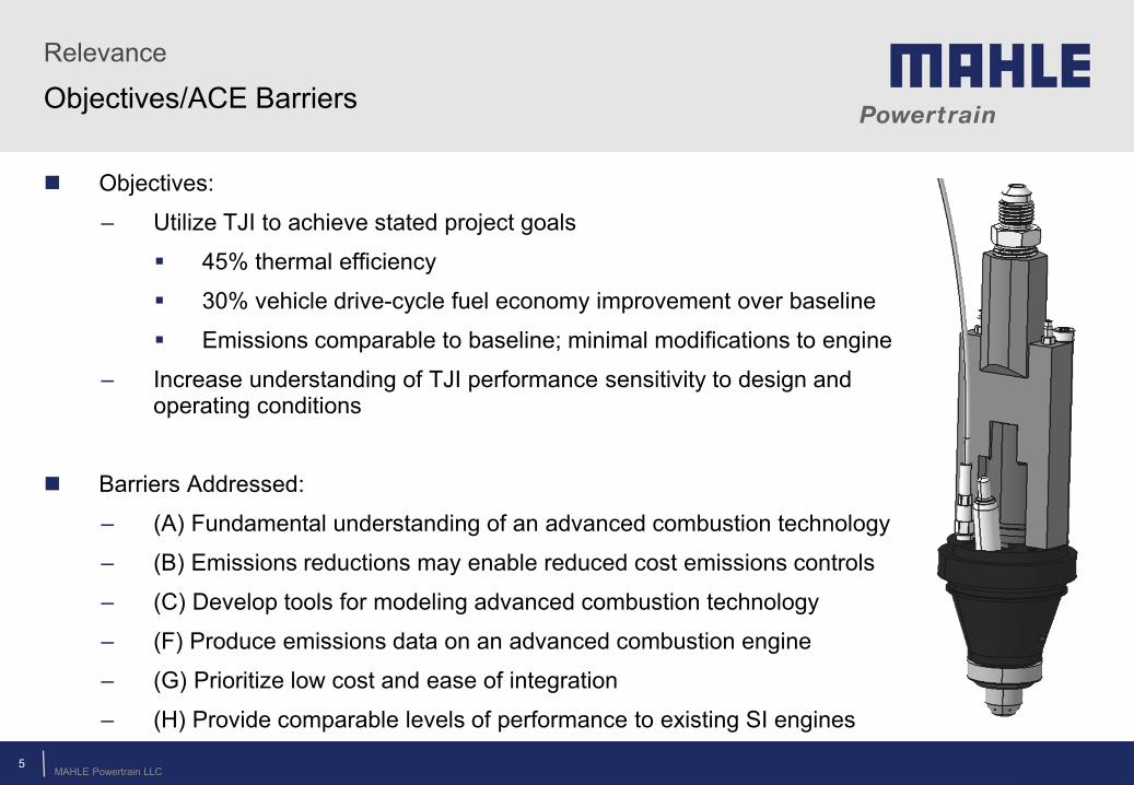
Objectives:
– Utilize TJI to achieve stated project goals
45% thermal efficiency
30% vehicle drive-cycle fuel economy improvement over baseline
Emissions comparable to baseline; minimal modifications to engine
– Increase understanding of TJI performance sensitivity to design and operating conditions
Barriers Addressed:
– (A) Fundamental understanding of an advanced combustion technology
– (B) Emissions reductions may enable reduced cost emissions controls
– (C) Develop tools for modeling advanced combustion technology
– (F) Produce emissions data on an advanced combustion engine
– (G) Prioritize low cost and ease of integration
– (H) Provide comparable levels of performance to existing SI engines
5

MAHLE Powertrain LLC
Approach
© MAHLE
Phase-Based Approach
6

MAHLE Powertrain LLC
Budget Period Milestones Completion Date1 M1 - Phase 1 Design Work Complete 7/25/20121 M2 - Component Procurement Complete 10/30/20122 M3 - Single-Cylinder Engine Testing Complete 6/4/20132 M4 - Phase 1 Complete 8/10/20132 M5 - Boosted Single-Cylinder Engine Shakedown Complete 10/30/20132 M6 - Design Optimization Complete 7/15/20142 M7 - Phase 2 Complete 11/15/20143 M8 - Boosted Multi-Cylinder Engine Build & Shakedown Complete 2/5/20153 M9 - Operating Parameter Optimization & Mini-Map Complete 5/1/20153 M10 - Project Complete 6/30/2015
Approach / Technical Accomplishments
© MAHLE
Milestones and Accomplishments Since 2014 AMR
Completed Phase 2
– Single cylinder metal engine with addition of boost rig
• Testing focused on pre-chamber design optimization
• Development of TJI operating strategy
– CFD model correlation to experimental data
Initiated Phase 3
– Multi-cylinder engine testing
• Testing focused on producing engine mini-map for drive cycle simulation input
7
Single-cylinder metal engine (Phases 1 and 2)
Multi-cylinder metal engine (Phase 3)
MAHLE Powertrain LLC 8
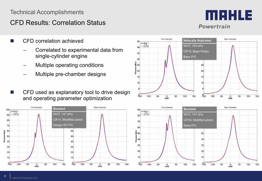
CFD correlation achieved
– Correlated to experimental data from single-cylinder engine
– Multiple operating conditions
– Multiple pre-chamber designs
CFD used as explanatory tool to drive design and operating parameter optimization
CFD Results: Correlation Status Technical Accomplishments
© MAHLE
MAHLE Powertrain LLC 9
Technical Accomplishments
© MAHLE
CFD Results: Model Purpose
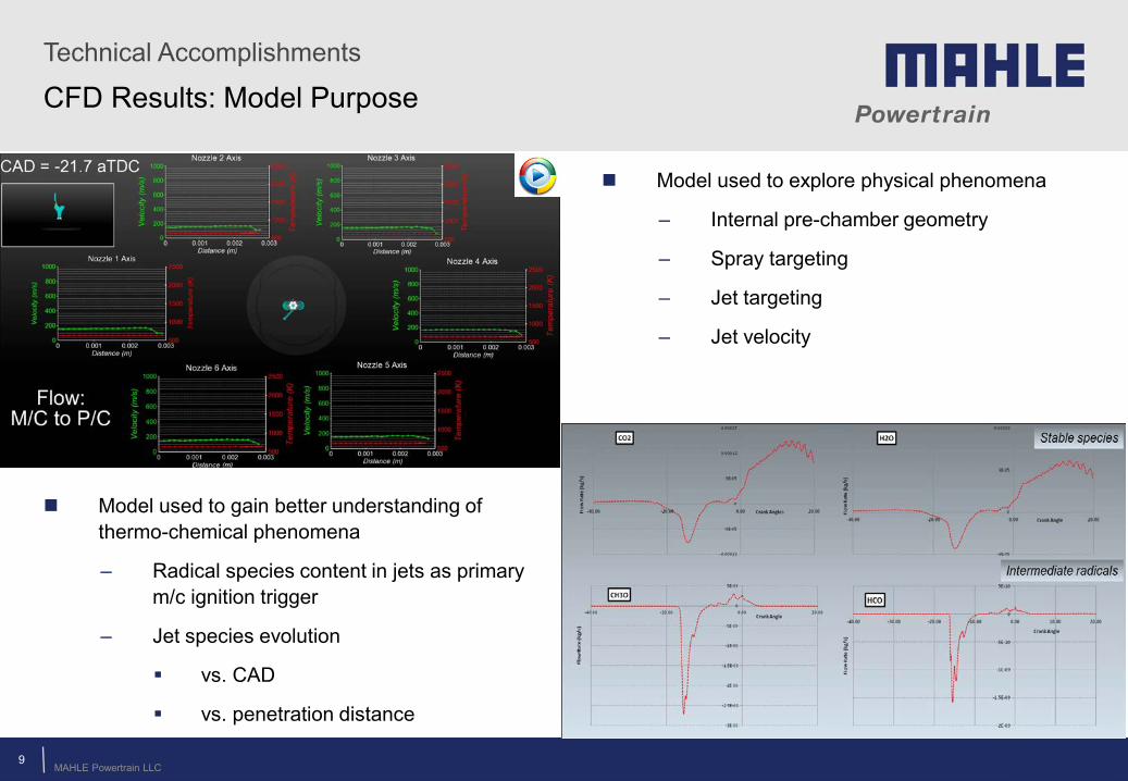
Model used to gain better understanding of thermo-chemical phenomena
– Radical species content in jets as primary m/c ignition trigger
– Jet species evolution
vs. CAD
vs. penetration distance
Model used to explore physical phenomena
– Internal pre-chamber geometry
– Spray targeting
– Jet targeting
– Jet velocity
MAHLE Powertrain LLC
Technical Accomplishments
© MAHLE 10
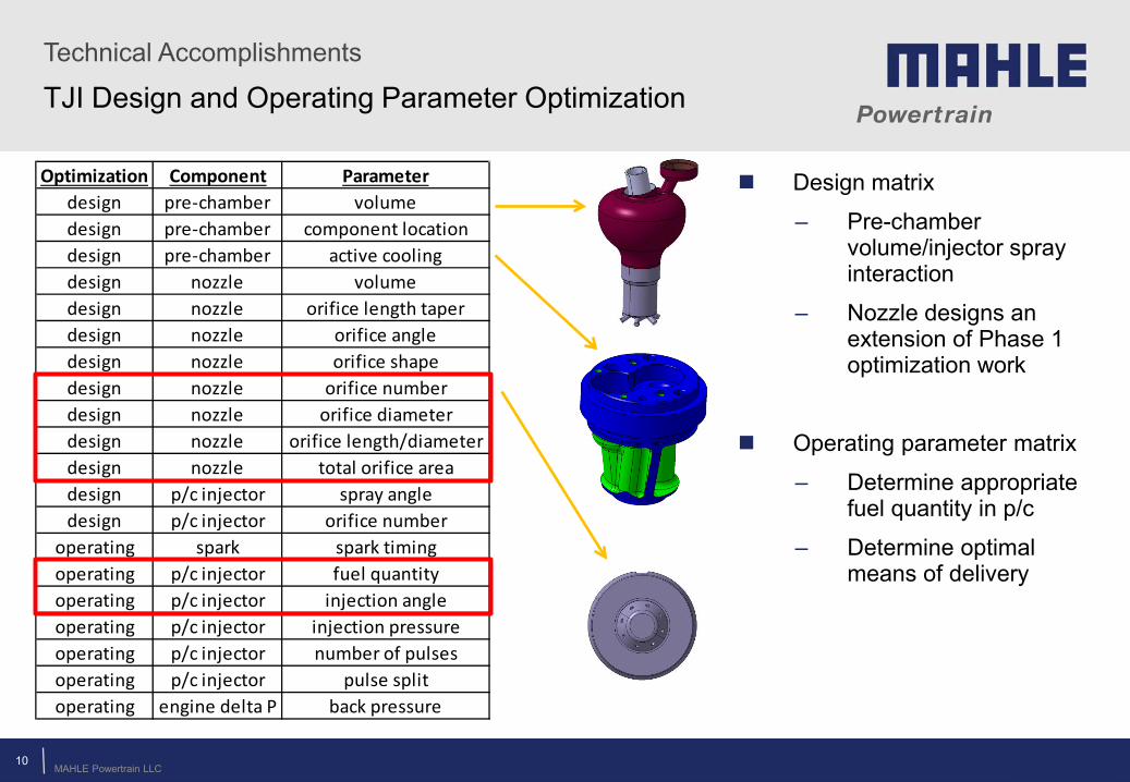
TJI Design and Operating Parameter Optimization
Design matrix
– Pre-chamber volume/injector spray interaction
– Nozzle designs an extension of Phase 1 optimization work
Operating parameter matrix
– Determine appropriate fuel quantity in p/c
– Determine optimal means of delivery
Optimization Component Parameterdesign pre-chamber volumedesign pre-chamber component locationdesign pre-chamber active coolingdesign nozzle volumedesign nozzle orifice length taperdesign nozzle orifice angledesign nozzle orifice shapedesign nozzle orifice numberdesign nozzle orifice diameterdesign nozzle orifice length/diameterdesign nozzle total orifice areadesign p/c injector spray angledesign p/c injector orifice number
operating spark spark timingoperating p/c injector fuel quantityoperating p/c injector injection angleoperating p/c injector injection pressureoperating p/c injector number of pulsesoperating p/c injector pulse splitoperating engine delta P back pressure
MAHLE Powertrain LLC
Technical Accomplishments
© MAHLE
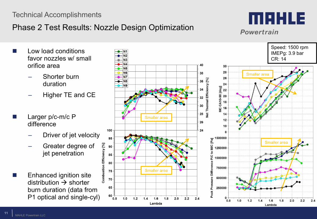
Phase 2 Test Results: Nozzle Design Optimization
Low load conditions favor nozzles w/ small orifice area
– Shorter burn duration
– Higher TE and CE
Larger p/c-m/c P difference
– Driver of jet velocity
– Greater degree of jet penetration
Enhanced ignition site distribution shorter burn duration (data from P1 optical and single-cyl)
Speed: 1500 rpm IMEPg: 3.9 bar CR: 14
Smaller area
Smaller area
Smaller area
Smaller area
11
MAHLE Powertrain LLC
Technical Accomplishments
© MAHLE
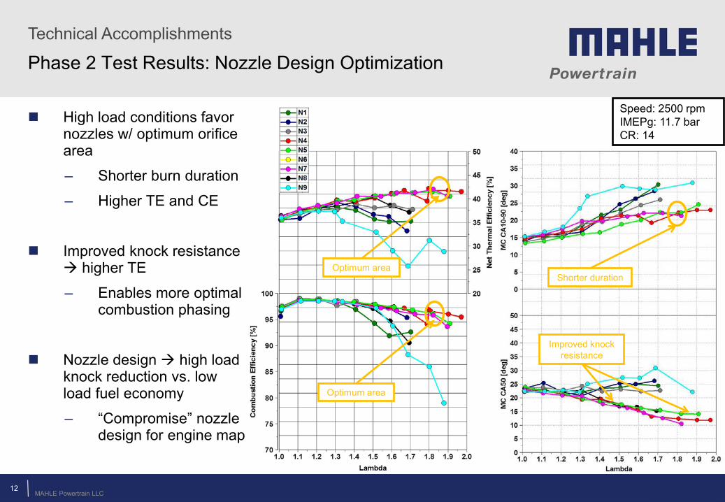
Phase 2 Test Results: Nozzle Design Optimization
High load conditions favor nozzles w/ optimum orifice area
– Shorter burn duration
– Higher TE and CE
Improved knock resistance higher TE
– Enables more optimal combustion phasing
Nozzle design high load knock reduction vs. low load fuel economy
– “Compromise” nozzle design for engine map
Speed: 2500 rpm IMEPg: 11.7 bar CR: 14
Optimum area
Optimum area
Improved knock resistance
Shorter duration
12
MAHLE Powertrain LLC
Technical Accomplishments
© MAHLE
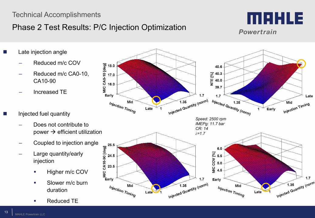
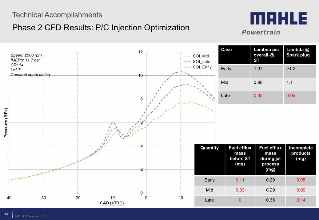
Phase 2 Test Results: P/C Injection Optimization
13
Late injection angle
– Reduced m/c COV
– Reduced m/c CA0-10, CA10-90
– Increased TE
Injected fuel quantity
– Does not contribute to power efficient utilization
– Coupled to injection angle
– Large quantity/early injection
Higher m/c COV
Slower m/c burn duration
Reduced TE
Speed: 2500 rpm IMEPg: 11.7 bar CR: 14 λ=1.7
MAHLE Powertrain LLC
Technical Accomplishments
© MAHLE
Phase 2 CFD Results: P/C Injection Optimization
Quantity Fuel efflux mass
before ST (mg)
Fuel efflux mass
during jet process
(mg)
Incomplete products
(mg)
Early 0.11 0.29 0.05
Mid 0.03 0.29 0.09
Late 0 0.35 0.14
14
Case Lambda p/c overall @ ST
Lambda @ Spark plug
Early
1.07 >1.2
Mid 0.98 1.1
Late 0.92 0.95
Speed: 2500 rpm IMEPg: 11.7 bar CR: 14 λ=1.7 Constant spark timing
MAHLE Powertrain LLC
Technical Accomplishments
© MAHLE
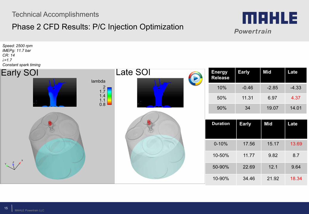
Phase 2 CFD Results: P/C Injection Optimization
Energy Release
Early Mid Late
10% -0.46 -2.85 -4.33
50% 11.31 6.97 4.37
90% 34 19.07 14.01
Duration Early Mid
Late
0-10% 17.56 15.17 13.69
10-50% 11.77 9.82 8.7
50-90% 22.69 12.1 9.64
10-90% 34.46 21.92 18.34
15
Speed: 2500 rpm IMEPg: 11.7 bar CR: 14 λ=1.7 Constant spark timing
MAHLE Powertrain LLC 16
Technical Accomplishments
© MAHLE
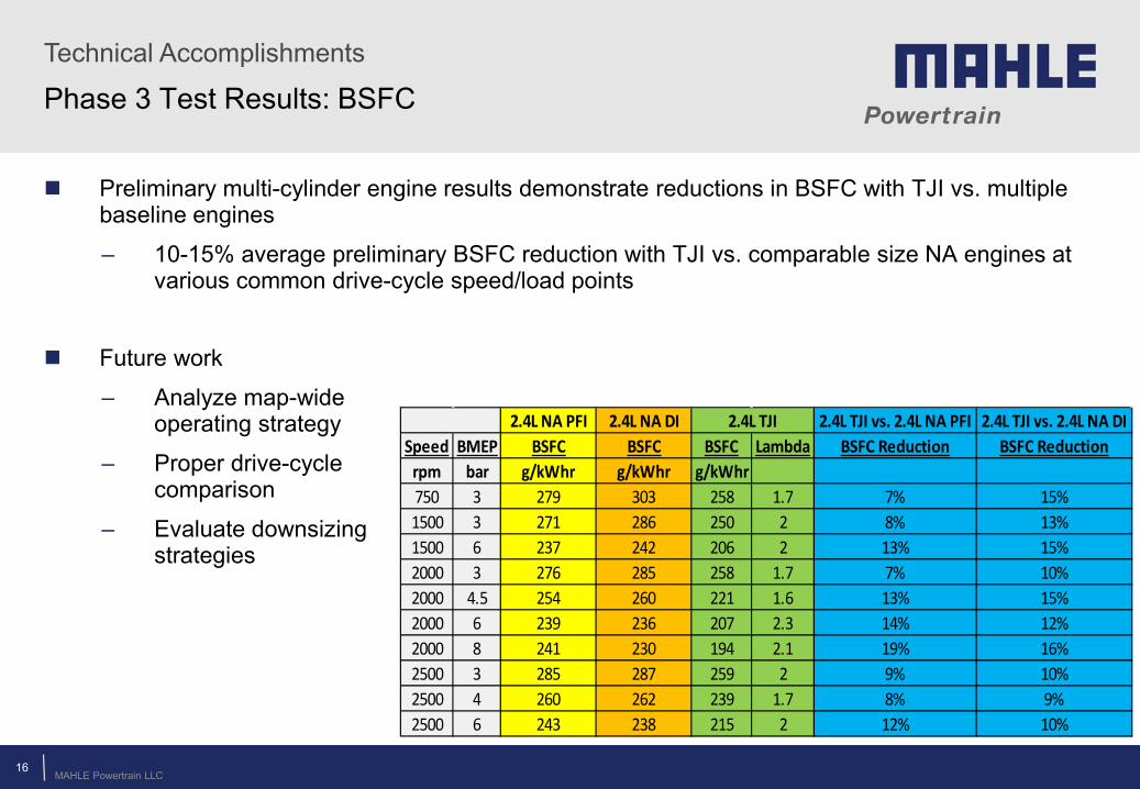
Phase 3 Test Results: BSFC
Preliminary multi-cylinder engine results demonstrate reductions in BSFC with TJI vs. multiple baseline engines
– 10-15% average preliminary BSFC reduction with TJI vs. comparable size NA engines at various common drive-cycle speed/load points
2.4L NA PFI 2.4L NA DI 2.4L TJI vs. 2.4L NA PFI 2.4L TJI vs. 2.4L NA DI
Speed BMEP BSFC BSFC BSFC Lambda BSFC Reduction BSFC Reductionrpm bar g/kWhr g/kWhr g/kWhr750 3 279 303 258 1.7 7% 15%1500 3 271 286 250 2 8% 13%1500 6 237 242 206 2 13% 15%2000 3 276 285 258 1.7 7% 10%2000 4.5 254 260 221 1.6 13% 15%2000 6 239 236 207 2.3 14% 12%2000 8 241 230 194 2.1 19% 16%2500 3 285 287 259 2 9% 10%2500 4 260 262 239 1.7 8% 9%2500 6 243 238 215 2 12% 10%
2.4L TJI
Future work
– Analyze map-wide operating strategy
– Proper drive-cycle comparison
– Evaluate downsizing strategies
MAHLE Powertrain LLC 17
Technical Accomplishments
© MAHLE
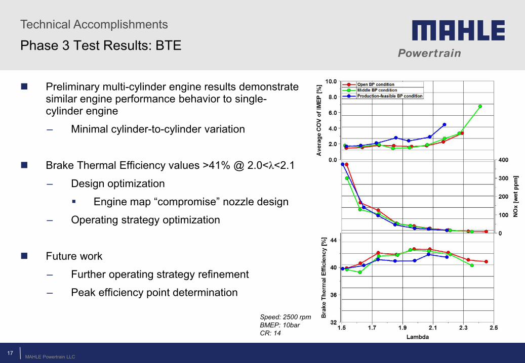
Phase 3 Test Results: BTE
Preliminary multi-cylinder engine results demonstrate similar engine performance behavior to single-cylinder engine
– Minimal cylinder-to-cylinder variation
Brake Thermal Efficiency values >41% @ 2.0<λ<2.1
– Design optimization
Engine map “compromise” nozzle design
– Operating strategy optimization
Future work
– Further operating strategy refinement
– Peak efficiency point determination
Speed: 2500 rpm BMEP: 10bar CR: 14
MAHLE Powertrain LLC
Merit Review Comments
© MAHLE
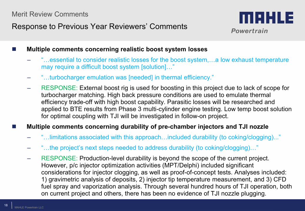
Response to Previous Year Reviewers’ Comments
Multiple comments concerning realistic boost system losses – “…essential to consider realistic losses for the boost system,…a low exhaust temperature
may require a difficult boost system [solution]…”
– “…turbocharger emulation was [needed] in thermal efficiency.”
– RESPONSE: External boost rig is used for boosting in this project due to lack of scope for turbocharger matching. High back pressure conditions are used to emulate thermal efficiency trade-off with high boost capability. Parasitic losses will be researched and applied to BTE results from Phase 3 multi-cylinder engine testing. Low temp boost solution for optimal coupling with TJI will be investigated in follow-on project.
Multiple comments concerning durability of pre-chamber injectors and TJI nozzle – “…limitations associated with this approach…included durability (to coking/clogging)...”
– “…the project’s next steps needed to address durability (to coking/clogging)…”
– RESPONSE: Production-level durability is beyond the scope of the current project. However, p/c injector optimization activities (MPT/Delphi) included significant considerations for injector clogging, as well as proof-of-concept tests. Analyses included: 1) gravimetric analysis of deposits, 2) injector tip temperature measurement, and 3) CFD fuel spray and vaporization analysis. Through several hundred hours of TJI operation, both on current project and others, there has been no evidence of TJI nozzle plugging.
18
MAHLE Powertrain LLC
Collaborations and Coordination
© MAHLE
Collaborations
Ford Motor Company – Project Partner
– Donated engine hardware, offered technical advice, are participating in data sharing
Delphi Corporation – Project Subcontractor
– Supplied pre-chamber fuel injectors and conducted CFD analysis on fuel injection characteristics, offered technical advice
Spectral Energies LLC – Project Subcontractor
– Acquired optical engine data, contributed to post-processing
University Collaboration
– Engaged multiple universities concerning further TJI investigation
19
MAHLE Powertrain LLC 20
Future Work
© MAHLE
Upcoming Project Work and Challenges
Future Work
Phase 3:
– Complete multi-cylinder engine testing
Mini-map generation
– Complete 1D vehicle drive-cycle analysis
System-level analysis of TJI operating strategy across engine map
Key Challenges
Challenge: Achieving 30% vehicle drive-cycle fuel economy improvement with TJI
– Multi-cylinder TJI engine testing is necessary to determine accurate brake specific fuel consumption
Challenge: Optimization of CR/knock reduction/peak efficiency/degree of downsizing
– System-level optimization of engine geometry/operating parameters to maximize efficiency according to preferred operation
MAHLE Powertrain LLC
Summary
© MAHLE
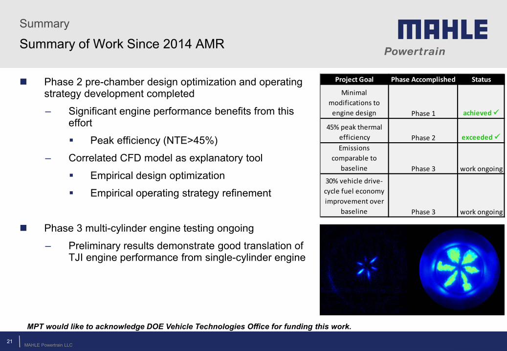
Summary of Work Since 2014 AMR
Phase 2 pre-chamber design optimization and operating strategy development completed
– Significant engine performance benefits from this effort
Peak efficiency (NTE>45%)
– Correlated CFD model as explanatory tool
Empirical design optimization
Empirical operating strategy refinement
Phase 3 multi-cylinder engine testing ongoing
– Preliminary results demonstrate good translation of TJI engine performance from single-cylinder engine
21
MPT would like to acknowledge DOE Vehicle Technologies Office for funding this work.
Project Goal Phase Accomplished Status
Minimal modifications to
engine design Phase 1 achieved
45% peak thermal efficiency Phase 2 exceeded Emissions
comparable to baseline Phase 3 work ongoing
30% vehicle drive-cycle fuel economy improvement over
baseline Phase 3 work ongoing
© MAHLE
Thank you for your attention
22

© MAHLE
Technical Back Up Slides
23
MAHLE Powertrain LLC
Relevance
Turbulent Jet Ignition Overview
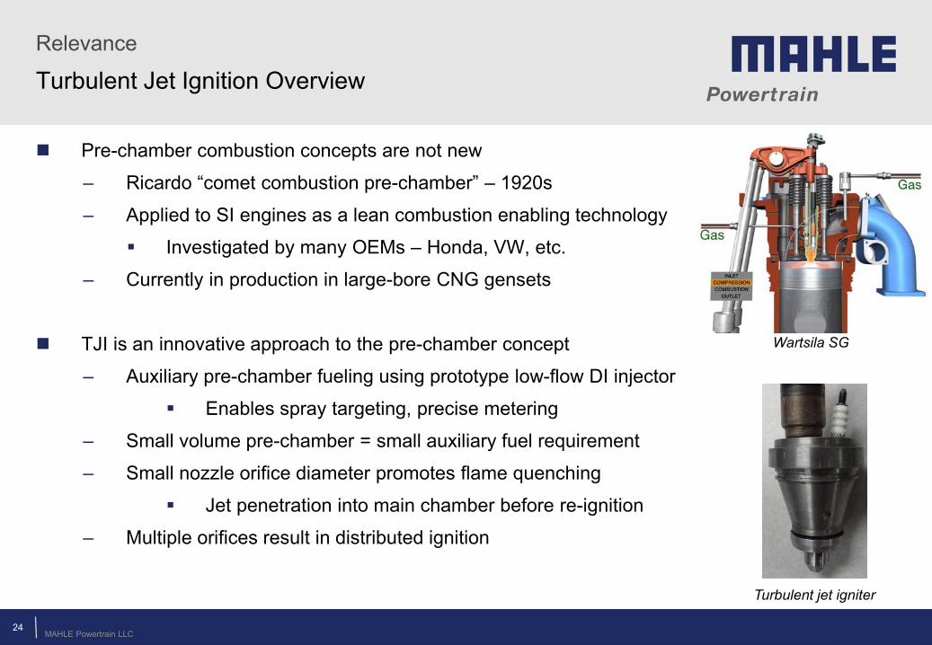
Pre-chamber combustion concepts are not new
– Ricardo “comet combustion pre-chamber” – 1920s
– Applied to SI engines as a lean combustion enabling technology
Investigated by many OEMs – Honda, VW, etc.
– Currently in production in large-bore CNG gensets
TJI is an innovative approach to the pre-chamber concept
– Auxiliary pre-chamber fueling using prototype low-flow DI injector
Enables spray targeting, precise metering
– Small volume pre-chamber = small auxiliary fuel requirement
– Small nozzle orifice diameter promotes flame quenching
Jet penetration into main chamber before re-ignition
– Multiple orifices result in distributed ignition
24 © MAHLE
Wartsila SG
Turbulent jet igniter
MAHLE Powertrain LLC
Technical Accomplishments
© MAHLE
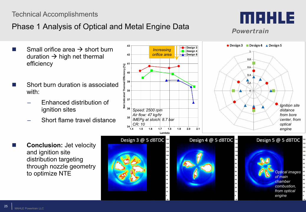
Phase 1 Analysis of Optical and Metal Engine Data
Small orifice area short burn duration high net thermal efficiency
Short burn duration is associated with:
– Enhanced distribution of ignition sites
– Short flame travel distance
Ignition site distance from bore center, from optical engine
Optical images of main chamber combustion, from optical engine
25
Conclusion: Jet velocity and ignition site distribution targeting through nozzle geometry to optimize NTE
Speed: 2500 rpm Air flow: 47 kg/hr IMEPg at stoich: 8.7 bar CR: 10
Increasing orifice area
MAHLE Powertrain LLC
Technical Accomplishments
© MAHLE
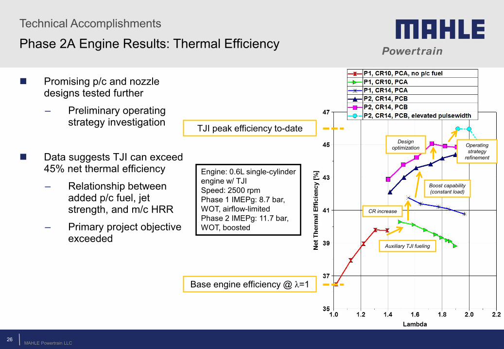
Phase 2A Engine Results: Thermal Efficiency
Promising p/c and nozzle designs tested further
– Preliminary operating strategy investigation
Data suggests TJI can exceed 45% net thermal efficiency
– Relationship between added p/c fuel, jet strength, and m/c HRR
– Primary project objective exceeded
TJI peak efficiency to-date
Engine: 0.6L single-cylinder engine w/ TJI Speed: 2500 rpm Phase 1 IMEPg: 8.7 bar, WOT, airflow-limited Phase 2 IMEPg: 11.7 bar, WOT, boosted
Base engine efficiency @ λ=1
Auxiliary TJI fueling
CR increase
Boost capability (constant load)
Operating strategy
refinement
Design optimization
26
MAHLE Powertrain LLC
Technical Accomplishments
© MAHLE
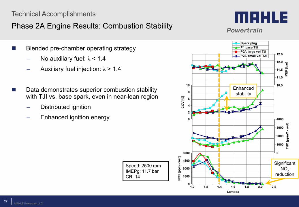
Phase 2A Engine Results: Combustion Stability
Blended pre-chamber operating strategy
– No auxiliary fuel: λ < 1.4
– Auxiliary fuel injection: λ > 1.4
Data demonstrates superior combustion stability with TJI vs. base spark, even in near-lean region
– Distributed ignition
– Enhanced ignition energy
Significant NOx
reduction
Speed: 2500 rpm IMEPg: 11.7 bar CR: 14
Enhanced stability
27
MAHLE Powertrain LLC
Technical Accomplishments
© MAHLE 28
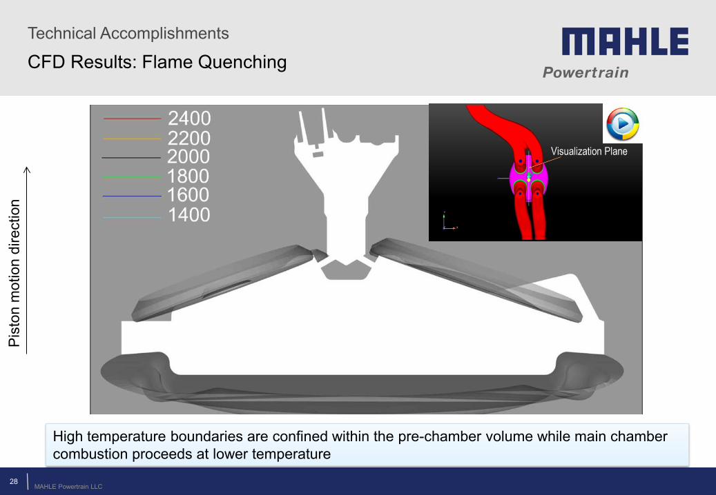
High temperature boundaries are confined within the pre-chamber volume while main chamber combustion proceeds at lower temperature
Pis
ton
mot
ion
dire
ctio
n
CFD Results: Flame Quenching