Embed Size (px)
Citation preview

Newspaper cartoon from the early 60’s

NVIS for Emergency NVIS for Emergency CommunicationsCommunications
Ross MazzolaMonroe County (NY) ARES
Ross MazzolaMonroe County (NY) ARES

Why NVIS?

Damage to InfrastructureDamage to Infrastructure
Inoperative Towers &Inoperative Towers &Inoperative Towers & Repeater Sites
Inoperative Towers & Repeater Sites
Loss of Backup PowerLoss of Backup Power

Difficult TerrainDifficult Terrain
ValleysValleysCanyonsMountainsForestsForestsJungles

What is NVIS?
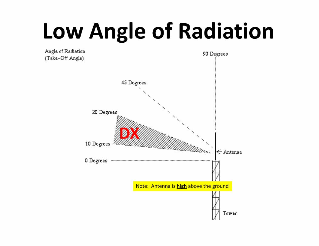
Low Angle of Radiation
DXDX
Note: Antenna is high above the ground

NVIS DefinitionNote: Attenuation on NVIS path is less than DX path because the RF takes the shortest possible trip through the ionosphere's highly b bi D labsorbing D‐layer
Near‐Vertical Incident Skywave ("NVIS") is a mode of radio propagation using F‐Layer atmospheric refraction around 65° to 90° (near vertical)

High Angle of Radiation65 Degrees
NVIS
Note: Antenna is low to the ground

300‐400 mile Coverage is Typical
Note: Signals above 10 megahertz (approx.) cannot be reflected by the f2 layer They pass right through intolayer. They pass right through into space.

NVIS Covers the Skip Zone
200 MILES
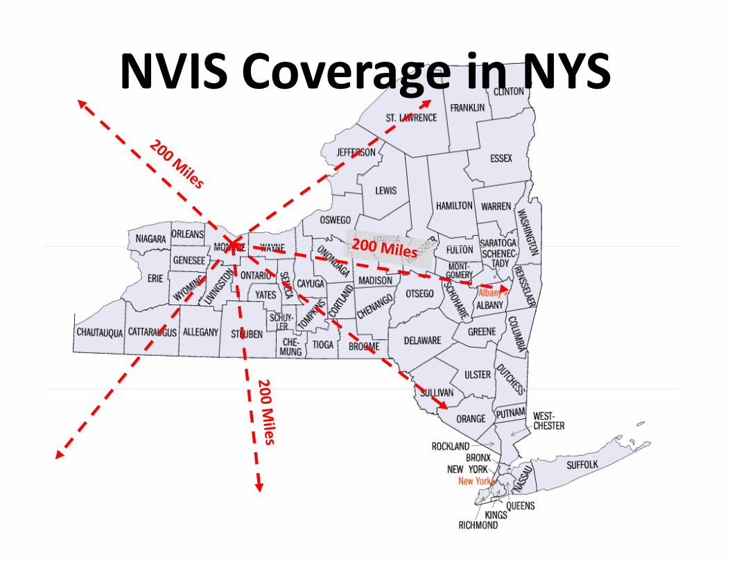
NVIS Coverage in NYS
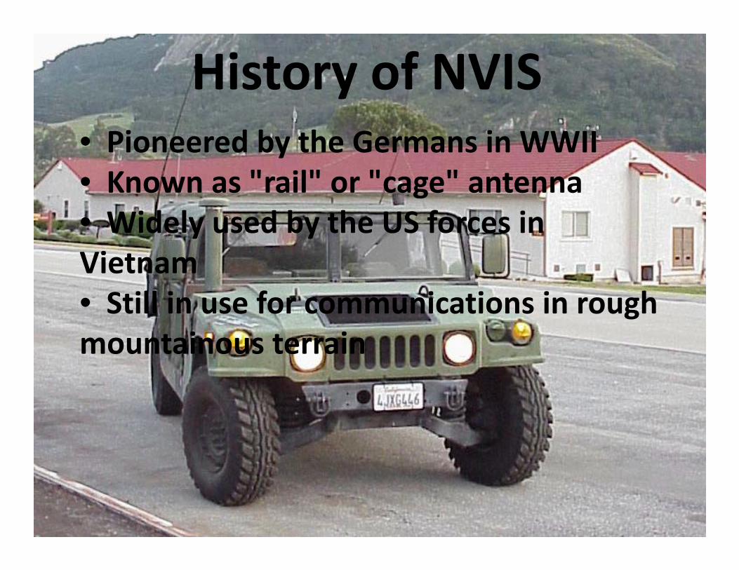
History of NVIS• Pioneered by the Germans in WWII• Known as "rail" or "cage" antenna• Known as "rail" or "cage" antenna• Widely used by the US forces in Vietnam• Still in use for communications in rough mountainous terrain

NVIS is a System• License to operate on HF
• Low‐Band Frequencies, typically 40m and 80m • E i t• Equipment
• HF Radio (100W is sufficient)• Tuner (only if necessary)
• Emergency Power• Battery• GeneratorGenerator• Charging
• Frequency• C t F i U d• Correct Frequencies are Used• Frequency Coordination Plan
•Antenna• Direct RF upwards (“cloudwarmers”)

What FrequenciesWhat Frequencies Should I Use?Should I Use?

Critical Frequency• The highest frequency which the ionosphere will reflect vertically is called foF2• I d f NVIS i l t b t d t th th’• In order for NVIS signals to be returned to the earth’s surface, its frequency must be less than the critical frequency of the F‐layer• During daylight, the critical frequency is approx 5 to 10 MHz. After Sunset, the critical frequency drops throughout the night reaching a low of 2 to 5 MHz just before dawnthe night reaching a low of 2 to 5 MHz just before dawn
10 MHz

Critical Frequency
NightDay
These foF2 measurements from various sites are used to create a map of foF2. The maps below can be used as a guide to NVIS ionospheric frequency support.
Night(9 pm local)
Day(12 noon local)
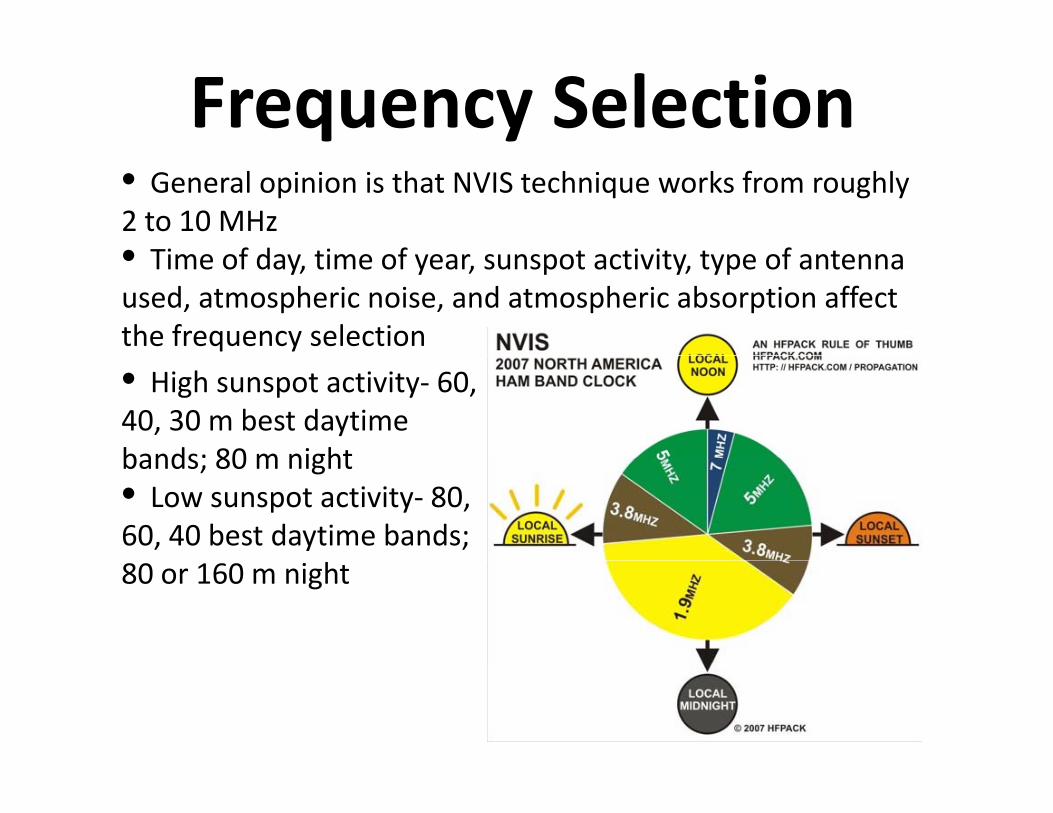
Frequency Selection• General opinion is that NVIS technique works from roughly 2 to 10 MHz • Ti f d ti f t ti it t f t• Time of day, time of year, sunspot activity, type of antenna used, atmospheric noise, and atmospheric absorption affect the frequency selection
• High sunspot activity‐ 60, 40, 30 m best daytime bands; 80 m nightbands; 80 m night• Low sunspot activity‐ 80, 60, 40 best daytime bands; 80 or 160 m night

Frequency Selection• The Critical Frequency is the key to successful NVIS working• A good “working” frequency for NVIS will often be between 10 15% b l i 85% f th F F2 C iti l F10 ‐ 15% below, i.e. 85% of the FoF2 Critical Frequency
foF2 CriticalClosest
Amateur Band10% below
foF2 Critical Frequency
15% below foF2 Critical Frequency
foF2 Critical Frequency (Mhz) from USA Map
Amateur Band Working NVIS
frequency (Mhz)
0.9 0.9 11.7 1.8 2 1.8 - 2.02.6 2.7 33 4 3 6 4 3 8 3 93.4 3.6 4 3.8 - 3.94.3 4.5 5 4.05.1 5.4 66.0 6.3 76.0 6.3 76.8 7.2 8 7.1 - 7.3
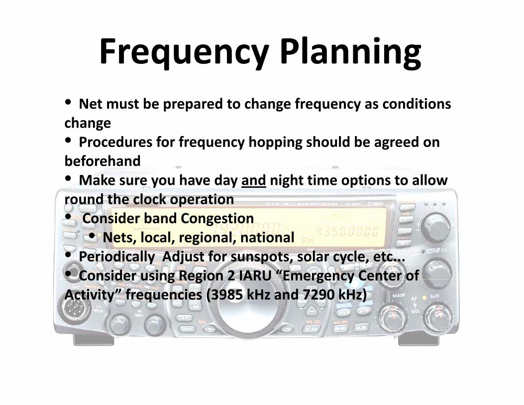
Frequency Planning• Net must be prepared to change frequency as conditions changechange• Procedures for frequency hopping should be agreed on beforehand• M k h d d i ht ti ti t ll• Make sure you have day and night time options to allow round the clock operation• Consider band Congestion
• Nets, local, regional, national• Periodically Adjust for sunspots, solar cycle, etc... • Consider using Region 2 IARU “Emergency Center ofConsider using Region 2 IARU Emergency Center of Activity” frequencies (3985 kHz and 7290 kHz)

NVIS Plan ExampleCourtesy of Marc Tarplee N4UFP
Winter Plan, SSB Nets
Local Time of Net Operating Frequency (1‐5)
Courtesy of Marc Tarplee, N4UFP
Local Time of Net Operating Frequency (1 5)
0001 – 0800 Primary: 3.996 MHz Alternate: 1.976 MHz0801 – 1600 Primary: 7.285 MHz Alternate: 5.40350 MHz1601 – 2000 Primary: 5.40350 MHz Alternate: 3.996 MHz2001 – 2400 Primary: 3 996 MHz Alternate: 1 976 MHz2001 – 2400 Primary: 3.996 MHz Alternate: 1.976 MHz
Summer Plan, SSB Nets
Local Time of Net Operating Frequency (1‐5)Local Time of Net Operating Frequency ( )
0001 – 0800 Primary: 3.996 MHz Alternate: 1.976 MHz0801 – 1600 Primary: 5.40350 MHz Alternate: 3.996 MHz1601 – 2400 Primary: 3.996 MHz Alternate: 1.976 MHz
Notes: (1) If primary frequency cannot support NVIS, the net will move to the alternate frequency for the time period in which the net is operating. If the alternate frequency cannot support NVIS, the net will move to the alternate frequency of the next later time period, if it is lower than the current alternate frequency. If the alternate frequency of the later time period is not lower, use the alternate frequency from the adjacent earlier time period, if it is lower. If a lower alternate frequency cannot be found, the net must be moved to VHF.(2) Band changes will occur at quarter hour intervals.(3) All operating frequencies, other than those in the 60m band, may vary by +/‐ 10 KHz to avoid interference.(4) Output power on 60m must be limited to 50 W PEP.(5) Only USB is allowed on 60 m

What AntennaWhat Antenna Should I Use?Should I Use?

Antennas• Key element for NVIS is the Antenna. Needs to radiate at very high takeoff angles• Field Expedient• Field Expedient
• Light weight• Easy/Quick to Erect• Easy to transport when disassembled
• Multi‐band• avg. NVIS freq. 3.5 Mhz (80m) and 7.3 Mhz (40m)g q ( ) ( )
• Direction of RF is primarily upwards (near vertical)• Easy to build• InexpensiveInexpensive• NVIS ANTENNAS ARE A COMPROMISE!!!!!!

Are You NVIS Now?
• Horizontal antennas mounted less than ¼ wavelength above ground have maximum radiation at high angles!
< ¼ Wavelength

Height Above Ground
• Single most controversial subject!• Height Above Groundg
• Below ¼ wave recommended• Some have found 10’ – 15’ height functions very well
h ffi i i b f• Some tests show NVIS efficiency is best at ten to 15 foot height for 40m to 75m frequency range
• Lowering the antenna to near 1/20th wavelength lowers g gthe background noise level
1/4 Wavelength

Gain
• As horizontal dipole moves closer to the earth, the gain begins to decrease because the ground is lossy
1/4 Wavelength1/8 Wavelength 1/4 Wavelength1/8 Wavelength

NVIS Antennas That Work• Loop Antenna
• Two Wavelength Loop Very effective, but not practical g p• Full Wavelength Loop
• Half wavelength Horizontal Dipolei l• Low Dipole
• Fan Dipole• Inverted VInverted V• Random Wire• “Dual Ham‐stick” short dipole

Horizontal Dipole
Note: Height should be < ¼ wave to ensure high takeoff angle. About 25’‐50’ on 80m and 12’‐25’ on 40m

Low Dipole• Two supports• Low = 1’ to 6’• Some designs use
reflector wires
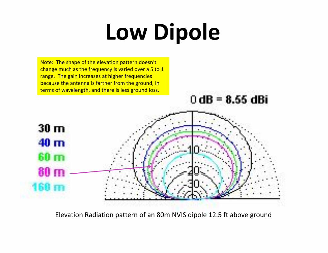
Low DipoleNote: The shape of the elevation pattern doesn’t change much as the frequency is varied over a 5 to 1 range. The gain increases at higher frequencies g g g qbecause the antenna is farther from the ground, in terms of wavelength, and there is less ground loss.
Elevation Radiation pattern of an 80m NVIS dipole 12.5 ft above ground
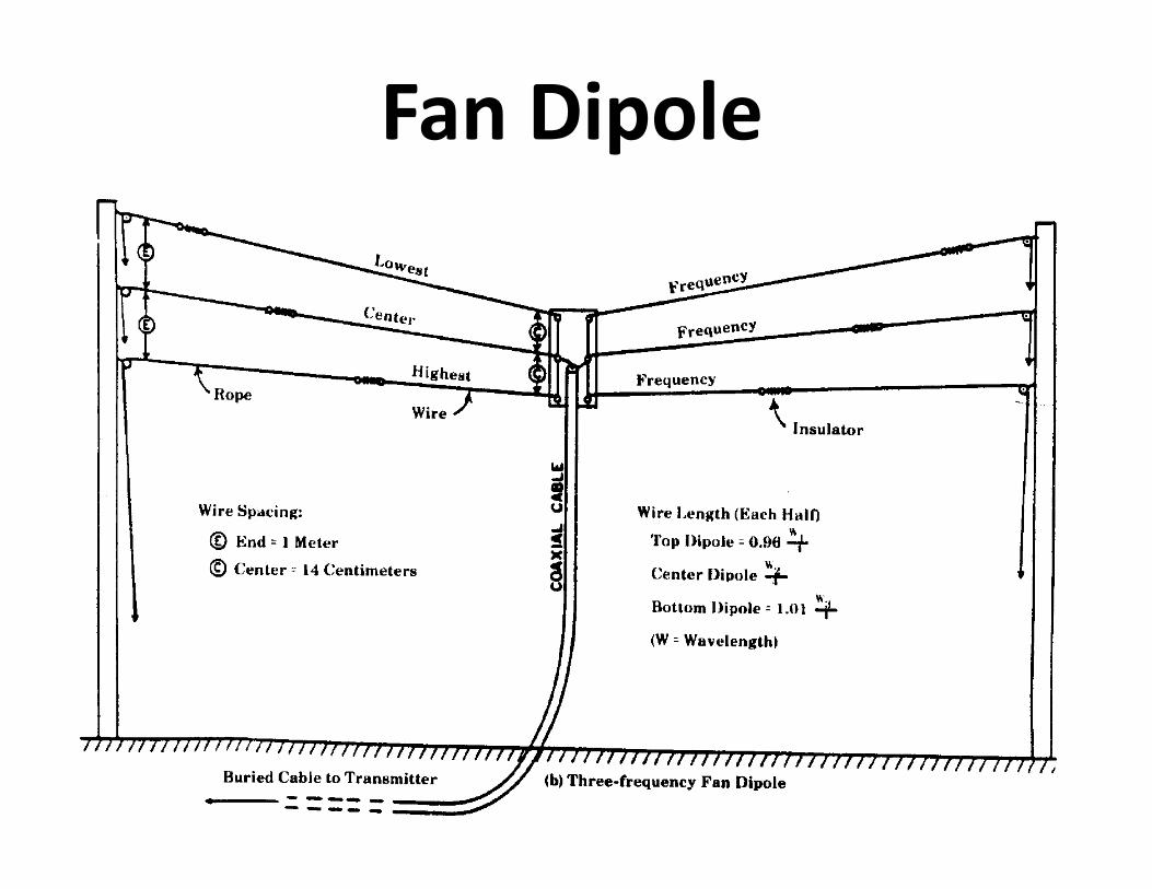
Fan Dipole

Inverted V

“Maypole” Style• Single support• Dual Band• Easy to erect• AS‐2259/GR
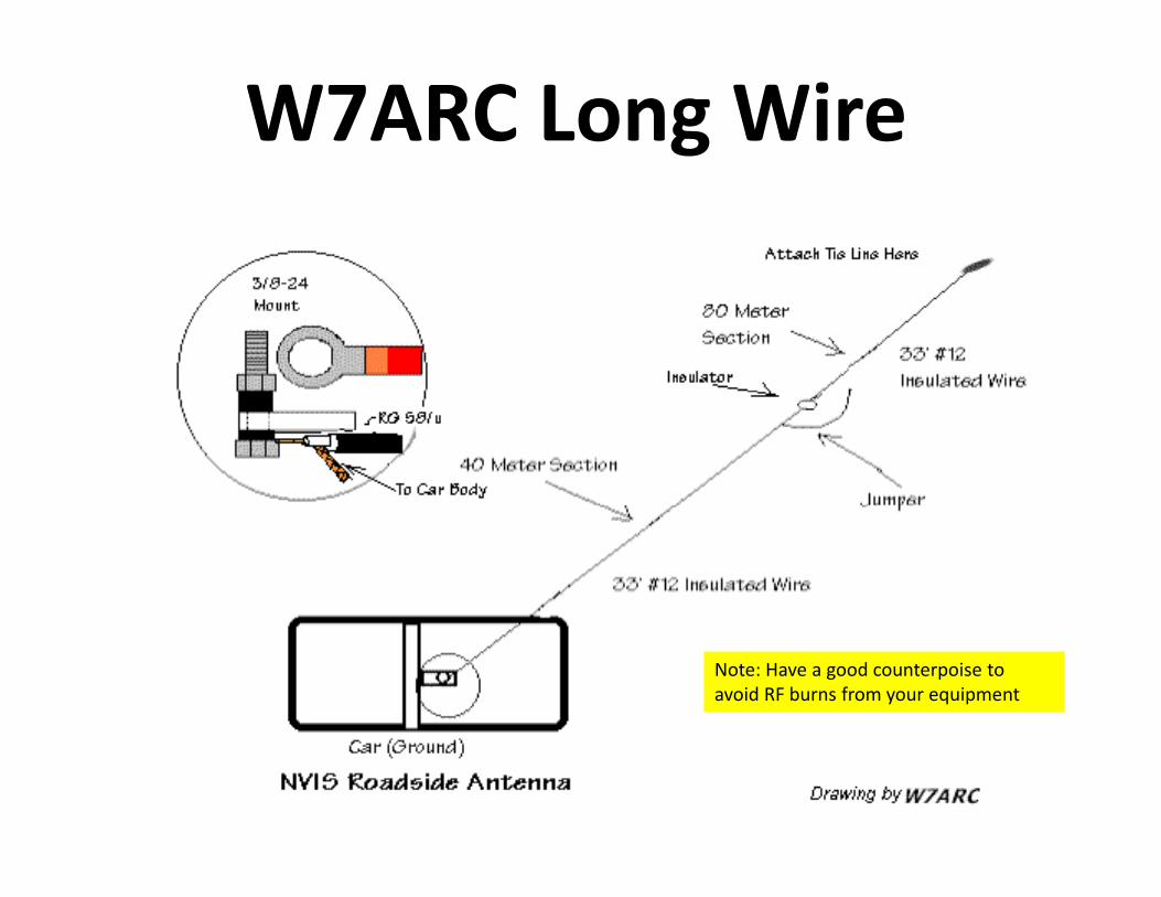
W7ARC Long Wire
Note: Have a good counterpoise to avoid RF burns from your equipment

Short Dipole (Mobile whips)
Courtesy of WA5ZNU
Other Proven NVIS Antennas
• Shirley Dipole• Patterson Loop• Any horizontally polarized antenna will have an NVIS
component in its radiation when placed below ¼ wavelength above ground
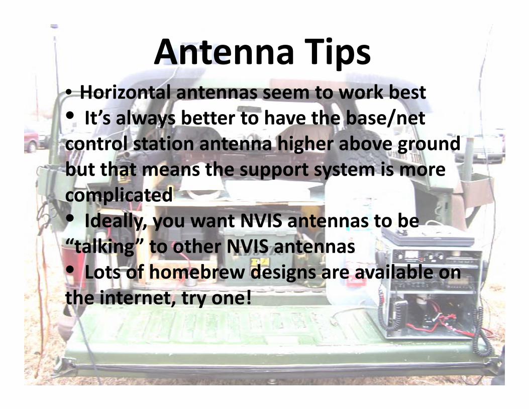
Antenna Tips• Horizontal antennas seem to work best• It’s always better to have the base/net y /control station antenna higher above ground but that means the support system is more pp ycomplicated• Ideally, you want NVIS antennas to be y y“talking” to other NVIS antennas• Lots of homebrew designs are available on gthe internet, try one!

S f t Fi tSafety First
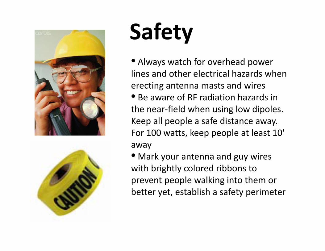
Safety• Always watch for overhead power lines and other electrical hazards when erecting antenna masts and wires• Be aware of RF radiation hazards in the near‐field when using low dipolesthe near‐field when using low dipoles. Keep all people a safe distance away. For 100 watts, keep people at least 10' away• Mark your antenna and guy wires with brightly colored ribbons to g yprevent people walking into them or better yet, establish a safety perimeter
SSummary

NVIS Hints & Tips• Lowering the antenna drops the noise level and changes
the “first bounce” distance• Low is convenient, but its also low in efficiency. And there
is a safety concern• Optimum dipole height is between 0 1 and 0 25Optimum dipole height is between 0.1 and 0.25
wavelength14' to 34' at 7.15 MHz26' to 65' at 3.75 MHz
• Best signal will be from stations in the 175‐300 mile range using NVIS antennasusing NVIS antennas
• Be prepared with some sort of "Plan B" involving communicating through alternate channels, or following some pre‐arranged scheme for trying all available frequency choices in a scheduled pattern of some sort
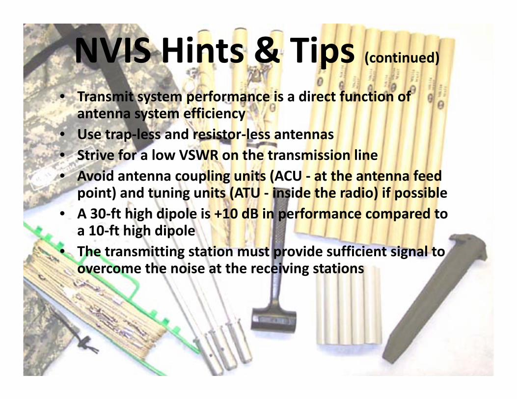
NVIS Hints & Tips (continued)• Transmit system performance is a direct function of
antenna system efficiency• Use trap‐less and resistor‐less antennas• Strive for a low VSWR on the transmission line• Avoid antenna coupling units (ACU at the antenna feed• Avoid antenna coupling units (ACU ‐ at the antenna feed
point) and tuning units (ATU ‐ inside the radio) if possible• A 30‐ft high dipole is +10 dB in performance compared to
f h h d la 10‐ft high dipole• The transmitting station must provide sufficient signal to
overcome the noise at the receiving stationsg

Linkswww.qsl.net/wb5ude/nvis/
www.athensarc.org/nvis.htm
th /f 2418 htwww.athensarc.org/fm2418m.htm
www.w0ipl.com/ECom/NVIS/nvis.htm
www co missoula mt us/acs/ACS/NVISpage1 htmwww.co.missoula.mt.us/acs/ACS/NVISpage1.htm
www.co.missoula.mt.us/acs/ACS/N6VNG%20AS2259.htmhttp://groups.yahoo.com/group/nvis/http://www.co.missoula.mt.us/acs/documents/TM%20NVIS%20antenna.pdfwww.arrl.org/qst/2005/12/Straw.pdfwww.arrl.org/qst/2005/12/Straw.pdfwww.tactical‐link.com/field_deployed_nvis.htm www.sedata.net/nvis.htmlwww cebik com/wire/cb htmlwww.cebik.com/wire/cb.html

Credits• “What’s the deal about NVIS”? By Dean Straw, N6BV, QST Dec 2005• “NVIS Operations” by Ed Farmer, AA6ZM, QST, Jan 1995• “The NVIS ‐ A Low Antenna for Regional Communications” by Albert
Pion, KK7XO, QST, Jun 2002• “NVIS Propagation and Antennas: Some Background Basics” by L.B.
C bik W4RNLCebik, W4RNL• “Understanding NVIS Antennas & Propagation” by Harold Melton,
KV5R, 2002, 2006US A fi ld l "FM 24 18" ( di M) b D Fi dl• US Army field manual "FM 24‐18" (appendix M) by Dave Fiedler
• “Antenna Performance for Near Vertical Incidence SkywaveCommunications” by Dave Fiedler“NVIS A t F d t l ” b Ed d F• “NVIS Antenna Fundamentals” by Edward Farmer
• “Near Vertical Incidence Sky Wave (NVIS) Propagation” by Marc Tarplee, N4UFP “N V ti l I id Sk (NVIS) A t ” b P t L b t• “Near Vertical Incidence Skywave (NVIS) Antenna” by Pat Lambert, W0IPL
Remember…

Questions