Embed Size (px)
Citation preview

2015 No.2N e w s l e t t e r
iMASTInstitute for Manufacturing and Sustainment Technologies
IN THIS ISSUE
DIRECTOR’S CORNER
New VLS Sealing Surface Method Repair a Success
Continued on Page 2
2015 No.2 iMAST News le t t e r 1
A U.S. Navy Manufacturing Technology Center of Excellence
Distr ibut ion Statement A: Approved for publ i c re l ea se ; d i s t r ibut ion unl imited .
Feature ArticleFocus on Materials ProcessingCeramic Thermal Spray Coatings for
Improved Wear Resistance and Life-Cycle for Submerged Materials and Mechanical Systems
Institute NotesCalendar of Events
Welcome to our second 2015 newsletter installment! Everyone’s busy this time of year, but Summer for iMAST means a lot of work to nail down our next year’s (FY 16) budget; present a full program review (project by project) to the Joint Defense Manufacturing Te c h n o l o g y Program; attend all of the OEM new project presentation meetings; and ensure our expiring year funds are well spent! You can probably relate to this within in your businesses or respective government organizations. I hope you can fit a vacation in as well! The new projects we’re starting to identify are designed for consideration as a FY 17 new start. In the ManTech annual project cycle, summer and early fall we talk to all the major acquisition program OEM’s and
Timothy D. Bair
by David Tomiyama, Public Affairs Specialist, Pearl Harbor Naval Shipyard [iMAST is once again pleased to note a successful Navy ManTech collaboration with the Pearl Harbor Naval Shipyard and the Naval Undersea Warfare Center Division Keyport. The following article was recently published in the Pearl Harbor Naval Shipyard’s bi-monthly news journal: Shipyard Log.]
The Shipyard successfully repaired a Vertical Launching System (VLS) missile tube on the USS Ashville (SSN 758) using a new repair method that saves time and sets the stage for future use on submarine availabilities. The use of the VLS sealing surface repair method began in December (2014) shortly before curtailment and finished in mid-January. “We didn’t work on the tube that needed the least amount of work,” said Eric Petran, Code 220 naval new technology program manager. “We wanted to prove the machine’s worth by tackling the tube that was in the worst shape possible. This particular tube revealed heavy electroplating which made it more difficult to repair.” The VLS sealing surface repair method uses a laser welding machine that performs three tasks. The first is to grind the inside of the missile tube down until the inner part is smooth all the way around. The grinding smooth’s out pot marks, scratches, corrosion and other defects that accumulate during the wear and tear of being underway. The second part of the process is laser welding corrosion resistant steel to the now smooth tube. The final piece is to grind the tube down to its original specifications. The traditional method involves Shipyarders brush plating a layer of copper to the tube. This method takes longer to accomplish and is physically taxing as the individual performs all work by hand in the tube. The mechanic must be precise otherwise the material peels if not applied
Continued on Page 7
View of tube with laser clad weld module installed.
U.S
. Nav
y re
lease
d ph
oto

DIRECTOR’S CORNER
DIRECTOR, iMAST &NAVY/MARINE CORPS REPAIR
TECHNOLOGIESTimothy D. Bair
(814) 863-3880 [email protected]
MATERIALS PROCESSING TECHNOLOGIESTimothy J. Eden, Ph.D.
(814) 865-5880 [email protected]
LASER PROCESSING TECHNOLOGIESRichard P. Martukanitz, Ph.D.
(814) 863-7282 [email protected]
COMPOSITES MATERIALSTECHNOLOGIES
Kevin L. Koudela, Ph.D.(814) 863-4351 [email protected]
MANUFACTURING SYSTEMS TECHNOLOGIESMark T. Traband, Ph.D.
(814) 865-3608 [email protected]
SYSTEMS OPERATIONS AND AUTOMATION/ COMPLEX SYSTEMS MONITORING
Eddie C. Crow(814) 863-9887 [email protected]
DRIVETRAIN TECHNOLOGIESNagesh Sonti, Ph.D.
(814) 865-6283 [email protected]
iMAST ADMINISTRATION and EDITORGregory J. Johnson
(814) 865-8207 [email protected]
FINANCIAL COORDINATORBrenda E. Kephart
(814) 865-3264 [email protected]
WORLD WIDE WEBhttp://www.arl.psu.edu/centers_imast.php
NAVY PROGRAM MANAGERGregory D. Woods
©2015. The iMAST newsletter is published by the Institute for Manufacturing and Sustainment Technologies of the Applied Research Laboratory at Penn State, University Park, PA. iMAST is sponsored by the U.S. Navy Manufacturing Technology (ManTech) Program, Office of Naval Research, under Navy Contract N00024-12-D-6404. Any opinions, findings, conclusions, or recommendations expressed within are those of the authors and do not necessarily reflect the views of the U.S. Navy. Send mail list requests or address corrections to: iMAST Administrator, ARL Penn State, P.O. Box 30, State College, PA 16804-0030 or e-mail: [email protected]. Parcel delivery address (UPS, FedEx, USPS): Rear, Research Building West,
North Atherton Street, State College, PA 16804.
This publication is availablein alternative media on request.
Penn State is an equal opportunity, affirmative action employer, and is committed to providing employment opportunities to minorities, women, veterans, individuals with disabilities, and other protected groups. Nondiscrimination: http://guru.psu.edu/
policies/AD85.html
U.Ed. ARL 15-35
2 2015 No.2 iMAST News le t t e r
Douglas E. Wolfe received his Ph.D. in Materials (2001), his M.S. degree in Materials Science and Engineering—with an option in Metallurgy (1996), and his B.S. degree in Ceramic Science and Engineering (1994) from The Pennsylvania State University. Dr. Wolfe currently serves as a Senior Research Associate at the Applied Research Laboratory, as well as an Associate Professor of Materials Science and Engineering (MATSE) and Engineering Science and Mechanics (ESM) at Penn State.
Dr. Wolfe is actively working on nano composite, nano layered, multi-layered, functionally graded, and multi-functional coatings and the enhancement of coating microstructures to tailor and improve the properties of vapor deposited coatings such as thermal barrier coatings, transition metal nitides, carbides, and borides, transition and rare-earth metal, for a variety of applications in the aerospace, defense, tooling, biomedical, nuclear, and optical industries, as well as corrosion resistant applications. Dr. Wolfe can be contacted at (814) 865-0316, or by email at <[email protected]>.
Tim Bair
PROFILE
Applied Research LaboratoryInstitute for Manufacturing andSustainment Technologies
get their feedback on areas they identify that, if improved, can save the Navy big bucks. As you might guess, the list starts out large and we may actually start 25-33% of the original list next year. Nonetheless, a necessary process as the centers, in collaboration with the OEM’s and program offices, qualify each as a priority and a worthy investment. This year the eligible systems include the CVN and DDG programs, the VCS and ORP programs and the F-35 and CH-53K on the Air side. Despite the similarity to sausage making, the process usually results in the right projects getting funded by the best center. Thankfully, the centers all work to ensure the projects they take on have the best chance of succeeding technically and implementing, i.e. putting metal on the ship. I truly believe that the Navy ManTech program pays for itself, several times over the tax payer’s investment. This edition is dedicated to two projects that were recently completed successfully, the Vertical Launch System – Laser Clad Repair System and a plasma spray coating optimization project for submerged components. The VLS – LCRS system is alive and well and refurbishing tubes at Pearl Harbor as you read. This project was a great example of collaboration (iMAST – ARL, Pearl Harbor Naval Shipyard, and
the Naval Underwater Center Keyport) and innovation. One tool to grind and clad repair that replaces a highly unreliable and short-lived process. In other words, a home run for the home team! This edition’s feature article is focused on a little understood and often overlooked process required by many submerged mechanical system components—thermal spray. Our goal in this project was simply to help implement Plasma Spray, a mature technology that is commercially common, as the solution to an ongoing availability challenge for critical U.S. Navy assets. What was achieved ended up saving many millions of dollars by avoiding a redesign effort. Secondarily, this effort will improve the coating performance for dozens of other Navy, Marine Corps and DoD applications. Thanks for taking time out to let us tell you how much your tax investment paid off! Please don’t hesitate to call or write if we can clarify or help.
COMPOSITESMATERIALS
TECHNOLOGIES
MATERIALSPROCESSING
TECHNOLOGIES
MECHANICAL DRIVETRANSMISSIONTECHNOLOGIES
LASERPROCESSING
TECHNOLOGIES
COMPLEX SYSTEMSMONITORING
TECHNOLOGIES
NAVY/MARINECORPS REPAIR
TECHNOLOGIES
MANUFACTURINGSYSTEMS
TECHNOLOGIES
Ceramic Thermal Spray Coatings for Improved Wear Resistance and Life-Cycle for Submerged Materials and Mechanical Systems
FEATURE ARTICLE
2015 No.2 iMAST News le t t e r 3
Focus on Materials Processing
by Douglas E. Wolfe, Ph.D. Todd A. Palmer, Ph.D.
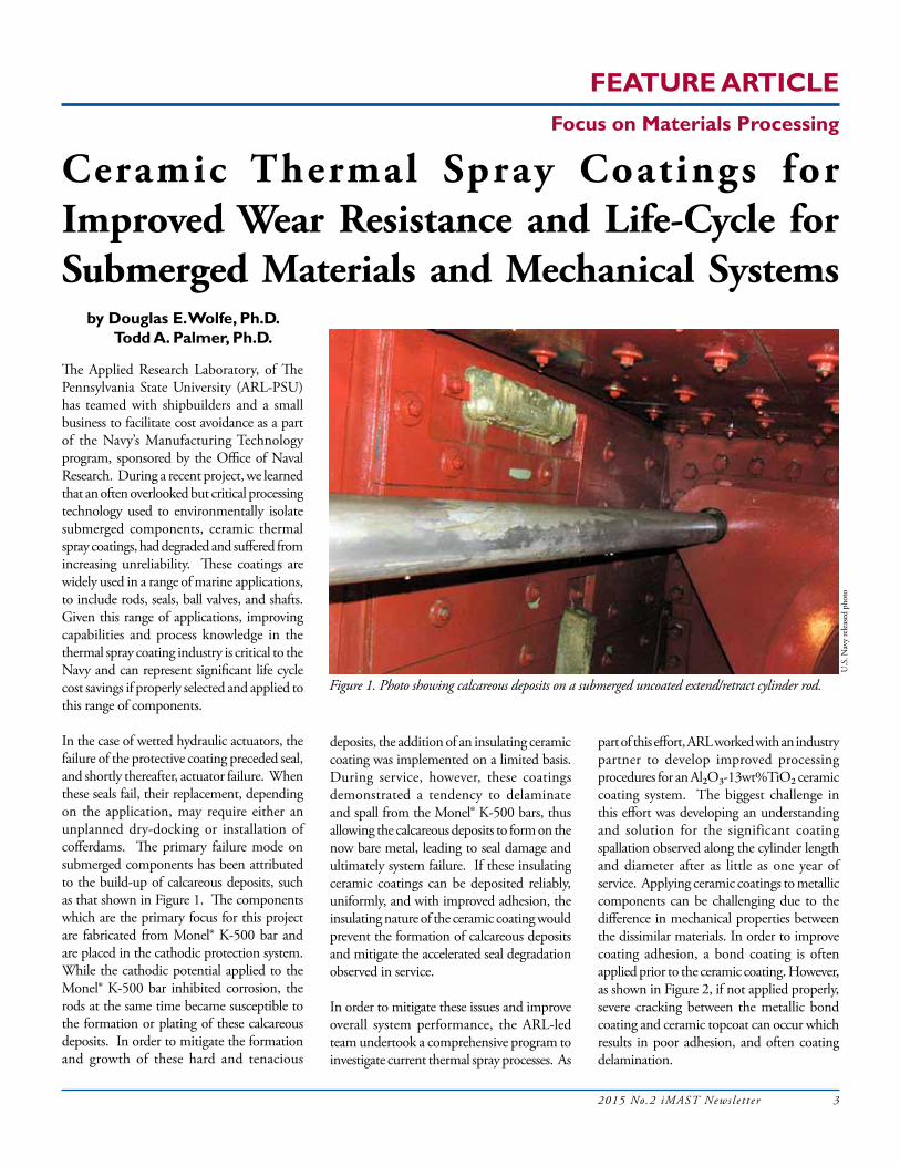
The Applied Research Laboratory, of The Pennsylvania State University (ARL-PSU) has teamed with shipbuilders and a small business to facilitate cost avoidance as a part of the Navy’s Manufacturing Technology program, sponsored by the Office of Naval Research. During a recent project, we learned that an often overlooked but critical processing technology used to environmentally isolate submerged components, ceramic thermal spray coatings, had degraded and suffered from increasing unreliability. These coatings are widely used in a range of marine applications, to include rods, seals, ball valves, and shafts. Given this range of applications, improving capabilities and process knowledge in the thermal spray coating industry is critical to the Navy and can represent significant life cycle cost savings if properly selected and applied to this range of components.
In the case of wetted hydraulic actuators, the failure of the protective coating preceded seal, and shortly thereafter, actuator failure. When these seals fail, their replacement, depending on the application, may require either an unplanned dry-docking or installation of cofferdams. The primary failure mode on submerged components has been attributed to the build-up of calcareous deposits, such as that shown in Figure 1. The components which are the primary focus for this project are fabricated from Monel® K-500 bar and are placed in the cathodic protection system. While the cathodic potential applied to the Monel® K-500 bar inhibited corrosion, the rods at the same time became susceptible to the formation or plating of these calcareous deposits. In order to mitigate the formation and growth of these hard and tenacious
deposits, the addition of an insulating ceramic coating was implemented on a limited basis. During service, however, these coatings demonstrated a tendency to delaminate and spall from the Monel® K-500 bars, thus allowing the calcareous deposits to form on the now bare metal, leading to seal damage and ultimately system failure. If these insulating ceramic coatings can be deposited reliably, uniformly, and with improved adhesion, the insulating nature of the ceramic coating would prevent the formation of calcareous deposits and mitigate the accelerated seal degradation observed in service.
In order to mitigate these issues and improve overall system performance, the ARL-led team undertook a comprehensive program to investigate current thermal spray processes. As
part of this effort, ARL worked with an industry partner to develop improved processing procedures for an Al2O3-13wt%TiO2 ceramic coating system. The biggest challenge in this effort was developing an understanding and solution for the significant coating spallation observed along the cylinder length and diameter after as little as one year of service. Applying ceramic coatings to metallic components can be challenging due to the difference in mechanical properties between the dissimilar materials. In order to improve coating adhesion, a bond coating is often applied prior to the ceramic coating. However, as shown in Figure 2, if not applied properly, severe cracking between the metallic bond coating and ceramic topcoat can occur which results in poor adhesion, and often coating delamination.
Figure 1. Photo showing calcareous deposits on a submerged uncoated extend/retract cylinder rod.
U.S
. Nav
y re
lease
d ph
oto

FEATURE ARTICLE
4 2015 No.2 iMAST News le t t e r
THERMAL SPRAY COATING FAILURE ANALYSISA post mortem analysis of failed ceramic thermal spray coatings provided significant insight into the coating system design and microstructure and what changes in the coating manufacturing processes needed to occur in order to improve coating adhesion and performance. Further investigation of a failed in-service rod showed indications that the coating manufacturing process could be improved, controlled, and optimized in order to yield higher performance. Three primary issues were identified during this investigation. They included coating thickness variations, cracking of the ceramic topcoat, and cracking along the topcoat/bondcoat interface and within the bond coat itself.
Figure 3 shows a coating thickness profile graph along the shaft diameter in which the coating did not meet the minimum thickness specification and displayed substantial local thickness variations in both the ceramic topcoat and the metallic bond coat. In some localized areas, no bond coating was observed which is catastrophic for ceramic coating adhesion. These coating thickness variations along the rod length and circumference led to variations in the coating durability due to differences in the coating microstructure.
The ceramic Al2O3-13wt%TiO2 topcoat showed horizontal and vertical cracking throughout the coating which could lead to premature coating delamination and spallation. Close examination of the ceramic
is used to heat, melt, or partially melt particles or wire stock. The resulting molten particles are then accelerated by a high speed process gas toward the component to be coated. These molten particles are traveling at a high velocity and impinge the substrate surface and rapidly cool, forming splats which are then built up to form the coating. In the Al2O3-13wt.%TiO2 coating system used here, the addition of 13wt.% TiO2 reduces the overall melting temperature compared to pure Al2O3 powder, since TiO2 (1854°C) has a lower melting temperature than Al2O3 (2040°C). These processes can be used to apply a wide variety of metallic, dielectric (ceramic), and mixed material combinations on a variety of substrate materials (metals, ceramics, polymers, composites, etc.), making it an affordable, versatile process, critical to Navy needs. However, improved performance is frequently required which can only be obtained by improved coating properties, especially adhesion strength, via microstructural improvements realized through process optimization.
In general, thermal spray coating processes fall within two general classifications: (a) temperature-based, where feedstock material is rendered molten (or partially molten) through its introduction into intense heat such as an arc, plasma, or flame prior to impingement onto a substrate (i.e., D-gun, plasma spray, and wire arc spray processes), and (b) velocity-based processes employing high particle
coating revealed variation in the coating density and/or degree of porosity. All of these observations strongly suggested that improvements in the thermal spray manufacturing process would yield a better coated component and assist in meeting the design requirements for the subject system.
Further analysis showed cracking between the ceramic topcoat and the metallic bond coating as well as a non-uniform and thick oxide layer at the interface at times, both of which lead to very low coating adhesion. Additional analysis of the metallic bond coating showed horizontal cracking within the metallic bond coat which indicated increased brittleness which usually results in lower coating adhesion. Careful investigation of the bond coating showed non-uniform bond coat thickness and microstructure including variation in the substrate/bond coat surface roughness and in some cases, no bond coating at all. Each of these issues can lead to variability in the coating adhesion strength, leading to the coating delamination issues observed in service. Therefore, a systematic approach was pursued by the ARL-led team to optimize the coating adhesion and microstructure.
THERMAL SPRAY COATING DEPOSITION PROCESSThermal spray coating processes are generally described as processes whereas the heat source
Figure 2. Stitched optical micrographs showing cracking between the ceramic topcoat and the metallic bond coat which resulted in poor adhesion. Also evident in the micrograph is the high volume fraction of porosity, which can limit coating mechanical properties.
crack crack
ARL
relea
sed
phot
o

FEATURE ARTICLE
2015 No.2 iMAST News le t t e r 5
velocities and accelerations, lower particle feedstock material temperatures, and shorter transient times (i.e., cold spray, high-velocity air-fuel (HVAF) and high velocity oxy-fuel (HVOF). In HVAF and HVOF, partial melting of powders may still occur depending on the process parameters.
THERMAL SPRAY COATING DEPOSITION PROCESS OPTIMIZATIONTo investigate the thermal spray ceramic coating process and improve the coating quality and adhesion, the team worked with a small business that supports the Navy with thermal spray coating services. Temperature and velocity, along with other plasma parameters, dictate the processing conditions. In order to better monitor the process, several major plasma processing parameters known to have a significant impact on the coating microstructure and properties were monitored during the manufacturing process and optimized in order to improve coating durability and adhesion.
During the early stages of coating development and optimization, both wire arc thermal spray and atmospheric plasma spray (APS) processes were used to improve coating performance. However, after several iterations, it was determined that the oxygen content in the metallic wire arc bond coating was the cause of the increased brittleness within the bond coating which was contributed to the poor
coating system adhesion. Therefore, APS of the Eutectic 21021 bond coating was investigated and resulted in over a 50% improvement in ceramic topcoat adhesion after optimization to values close to 5,000 psi.
The team sought to optimize the plasma spray processing parameters as coating properties are heavily dictated by the coating microstructure which is a strong function of the splat formation during thermal spray processing. There are several processing parameters available for optimization of the coating microstructure, but the primary parameters controlled here include stand-off distance, power (arc amperage, arc voltage), primary gas pressure and ratio, powder feed rate, powder type, traverse speed, and substrate surface roughness. These processing parameters control the powder-plasma characteristics which control the degree of melting and vaporization. For example, for a given plasma plume, lower powder feed rate provides a higher degree of melting and particle velocity which results in a higher density coating, and thus improved material performance. Power is a function of the amperage and voltage as well as the plasma gas flow type (Ar/He), which affect the particle temperature during transit, which then determines the degree of melting in the plasma plume, and ultimately, the coating phase and microstructure.
The type and morphology of the powders also have a significant impact on the microstructure
of the plasma sprayed coatings. Powder morphologies and size distributions will have different particle heating and thermal characteristics which will control the particle temperature and velocity, which thus control the splat formation and thus microstructure. The standoff distance or the distance between the nozzle and the rod (i.e., component to be coated) affects not only the substrate surface temperature, but also the particle velocity which influences the degree of flattening of the partially or fully melted particles which contributes to the degree of coating adhesion. The powder feed rate contributes to the degree of melting and splat formation which contributes to the degree of porosity and percent of un-melted particles which affects the coating performance; if too high a fraction of powder is not melted, poor adhesion/bonding can occur as well as reduced mechanical properties.
The team used a suite of analytical characterization equipment within the materials characterization laboratory at Penn State in order to map out the processing window including X-ray diffraction, scanning electron microscopy, energy dispersive spectroscopy, optical profilometry, and mechanical testing. Improved coating density was realized with optimized atmospheric thermal spray coating deposition processing parameters as shown by the scanning electron microscopy images of the polished cross sections of the ceramic topcoat in Figure 4.
Figure 3. Ceramic coating and metallic coating thickness plotted as a function of circumference along the outer diameter of the RBP showing (left) bond coating thickness out of design specification and (rod) non-uniform coating thickness resulting from poor thermal spray manufacturing process control, and also coating delamination.

6 2015 No.2 iMAST News le t t e r
The APS coating manufacturing processing window is a little tighter for some powder types as opposed to the coating deposition of the METCO® 130 powder, which is primarily synthesized from fused and crushed Al2O3 with TiO2 using a cladding process in which small TiO2 particles are attached to the larger Al2O3 particles. Powder characteristics are an important consideration for thermal spray coating processing in order to improve coating microstructure, properties, and performance. If the plasma characteristics are not ideal, un-melted and partially melted particles can become embedded into the coating resulting in poor performance.
It should be noted that the team uncovered variation in the methodology associated with coating adhesion. Depending on the type of adhesive (i.e., liquid or solid), the coating adhesion values could be artificially inflated by 100-300%. Therefore, tight test methods using the most aggressive coating adhesion tests in accordance with ASTM 633 and FM1000 adhesive, pushed the team to further optimize the ceramic/metallic thermal spray coating system in order to exceed design specification which resulted in improved coating durability.
The optimized coatings underwent realistic and aggressive testing and evaluation. In this coating testing and evaluation, in service conditions were realistically tested, and the coatings developed in this program underwent more than 4000 full performance cycles, which equates to over 70 years of service life. Additional process and quality control efforts were made as part of this program to
FEATURE ARTICLE
ensure that the coating quality was met across the expected manufacturing process. Since in process testing of coatings is difficult, a significant effort was made to test and evaluate specially designed endcaps that would be affixed to each production rod and allow for 100% inspection of the coated rods. Each of these endcaps contains adhesion test and microstructural evaluation samples that will be sprayed with each production rod and tested to ensure coating adhesion and durability on the in service components.
CONCLUSIONThe powder morphology and structure play a significant role in the coating manufacturing process and thus coating performance. Power characterization must be performed prior to coating processing to ensure the proper powder characteristics such as particle size, morphology, and particle size distribution. Critical plasma spray variables can be optimized by considering powder structure and morphology as one of the variables. In-process quality control should be implemented to increase process repeatability and enhance product quality. This includes the in-process inspection forms, QC inspection plan, and parameter record forms. Overall, combined shipbuilder and investigating team participation resulted in significant success in developing and fielding a substantially improved thermal spray manufacturing coating process. For this case alone, the implementation of a ceramic coated rod and vendor qualification will result in almost $300 Million in life cycle savings for the Navy. Technically, the understanding of the thermal
spray coating process resulted in significant improvements in test methodology, especially in how adhesion measurements should be made, as well as implementing improvements in the thermal spray coating deposition process and implementation of the endcap designs to ensure 100% rod sampling of coating properties to ensure coating adhesion and durability requirements are met.
ACKNOWLEDGEMENTThe authors would like to express their appreciation for support of this effort by the Institute for Manufacturing and Sustainment Technologies (iMAST), a U.S. Navy Center of Excellence under contract by the U.S. Navy Manufacturing Technology (ManTech) Program, Office of Naval Research. The authors would like to also thank all team members for working together throughout the program to make this project a significant success. Any opinions, findings, conclusions and recommendations expressed in this article are those of the author and do not necessarily reflect those of the U.S. Navy.
Figure 4. Scanning electron microscopy (SEM) images of the polished cross sections of ceramic topcoat deposited by Air Plasma Spray coating process showing (left) unoptimized and (right) improved coating manufacturing conditions in which coating density was increased and porosity reduced. (ARL released photo)
Thermal Spray Coating application.(ARL released photo)

2015 No.2 iMAST News le t t e r 7
INSTITUTE NOTES
COVER STORY
correctly. For the new method, Shipyarders monitor the machine’s performance at a work station a few feet away, topside of the boat. “It’s really uncomfortable brush plating with limited space as things can fall while performing the job from the top looking in,” said Jon Nagamine, Shop 38 machinery apprentice who performed VLS repairs using both methods. “It is a lot easier monitoring the laser welding machine and less labor intensive. What I especially like about laser welding is that it’s not a band aid or quick fix like brush plating where when a boat comes back you end up doing the same job again and again.
Laser welding is more permanent; it’s a total overhaul of the tube. In the future, we should have minimal repair requirements for missile tube work.” While happy with the results of sealing surface repair’s performance, Darwin Javier, Code 290 combat systems mechanical engineer, thinks it can perform even better. “We have held many meetings to improve the process,” he said. “We looked at the lessons we learned on the USS Chicago (SSN 721) and applied them to Asheville. We had a very productive hot wash after the Asheville availability. This was a good example of production engineering.” The VLS sealing surface repair method was first used by the Shipyard on the Chicago earlier this decade. Issues plagued the machine for years after its initial use until 2013, when Petran and a team comprised of Code 290, Code 920 and Code 138 and the Shipyard’s collaborative partners (The Pennsylvania State University’s Applied Research Laboratory and the Naval Undersea Warfare Center Division
Keyport) sought to come to a resolution and bring it back on line. Early, last year, the collaborative partners met with Shipyard production and engineering representatives here to test the VLS surface repair machine to see if it could be used on a future availability, which turned out to be Asheville. The machine is scheduled to be used on an upcoming Chief of Naval Operations availability. The Shipyard is currently the only naval shipyard to have this equipment. [For more information on this project effort contact iMAST PIs Ted Reutzel, Ph.D. at (814) 863-9891/email <[email protected]> or Stephen Brown at (814) 863-9889 / email <[email protected]>]
Continued from Page 1
U.S
. Nav
y re
lease
d ph
oto
Navy League Sea-Air-Space ExpoMembers of iMAST recently participated in the annual Navy League Sea-Air-Space Exposition held in National Harbor, Maryland. The Navy League Sea-Air-Space event is now the largest maritime exposition in the United States and continues to be an invaluable extension of the Navy League’s mission of maritime policy education and sea service support. The Sea-Air-Space Exposition brings the U.S. defense industrial base, private-sector U.S. companies, and key military decision makers together for an innovative, educational, professional and maritime based event. This year’s exposition marked the 50th anniversary of the event, which included 200 exhibits and highlighted unmanned vehicles, drones, and an unmanned submarine fleet. Speaking at the expo, the Chief of Naval Operations (Admiral Jon Greenert), said it’s time to bring simulators and virtual reality training to the whole fleet by bringing it to the waterfront so it can benefit Sailors in every rating. “The fidelity of virtual reality today is such that our folks can use touch screens to immerse in anything from starting a diesel engine, to launching a torpedo to working on an aircraft,” said Greenert. The Sea-Air-Space Exposition will continue to support the mission of the Navy League and lead the way as “THE” Exposition to attend each year to display the most current information and technology relevant to maritime policy.
Applied Research LaboratoryP.O. Box 30State College, PA 16804–0030
CHANGE SERVICE REQUESTED
U.S. PostagePAID
State College, PAPermit No. 1
8 2015 No.2 iMAST News le t t e r
CALENDAR of EVENTS 201523–25 Jun Mega Rust Newport News, VA
1–2 Sep Fleet Maintenance & Modernization Symposium San Diego, CA
22–24 Sep Modern Day Marine Expo ** Quantico, VA
12–14 Oct AUSA Expo Washington, D.C.
12–13 Dec ASNE Combat Systems Symposium Arlington, VA
30 Nov–3 Dec Defense Manufacturing Conference 2015 ** Phoenix, AZ
7-9 Dec DoD Maintenance Symposium Phoenix, AZ
201612–14 Jan Surface Navy Association Symposium ** Crystal City, VA
16–18 May Navy League Sea-Air-Space Expo ** National Harbor, MD
“Shipbuilding is a priority not only in the Navy budget but also with the Department of Defense and Congress.”—Sean Stackley, Assistant Secretary of the Navy for Research, Development and Acquisition
** Visit iMAST booth