Embed Size (px)
Citation preview

NewsletterSimulation Based Engineering & Sciences
Year n°2 Summer 201815
The art of CFD simulation brings art design to life
Using CAE to optimize thestructure of folding powerharrows
Evaluation of the optimization algorithmperformance on the calibration of the Cowper-Symonds analytical model
The Infinity Computer and applied infinities and infinitesimals
Simulating hot forging processes:moving from practical experienceinto new markets
Making calibration of multibody models more efficient
Using CAE to support fire safety engineering in the Condó road tunnel
ContentsCASE STUDIES4 The art of CFD simulation brings art design to life6 Using CAE to optimize the structure of power harrows9 BASF Catalysts solutions meet exhaust emissions
standards with modeFRONTIER10 Using CAE to support fire safety engineering in the
Condó road tunnel12 Simulating hot forging processes: moving from
practical experience into new markets14 Making calibration of multibody models more efficient
by pairing RecurDyn and modeFRONTIER17 Evaluation of the optimization algorithm performance
on the calibration of theCowper-Symonds analytical model for astrain-hardenable Al alloy
20 The 37th TechNet Alliance Meeting confirms the network’s central role in the global ANSYS environment
21 The Infinity Computer and applied infinities and infinitesimals
SOFTWARE UPDATES26 ConvectionLinks: EnginSoft develops a new APP for
ANSYS Workbench27 The 2018 release of the Flownex® Simulation
Environment is now available28 ESSS releases new version of Rocky DEM software30 New version of GENESIS 17.0 increases efficiency
and completeness31 Achieving large coverage testing using Virtual ECUs32 MapleSim provides substantial advantages for
adopters in the Heavy Machinery Industry34 Enabling safe, standards-based piping stress design
by all engineers, faster and more cost effectively38 New tools for material selection and optimization in
design40 The new modeFRONTIER 2018 spring release
EVENTS41 Figures and highlights from the 8th ESTECO
International Users’ Meeting42 Robotics. After the great success of the first edition,
the International Robotics Festival of Pisa returns from September 27th to October 3rd
43 2018 INTERNATIONAL CAE CONFERENCE AND EXHIBITION
Newsletter EnginSoftYear 15 n°2 - Summer 2018To receive a free copy of the next EnginSoft Newsletters, please contact our Marketing office at: [email protected]
All pictures are protected by copyright. Any reproduction of these pictures in any media and by any means is forbidden unless written authorization by EnginSoft has been obtained beforehand. ©Copyright EnginSoft Newsletter.
EnginSoft S.p.A.24126 BERGAMO c/o Parco Scientifico TecnologicoKilometro Rosso - Edificio A1, Via Stezzano 87Tel. +39 035 368711 • Fax +39 0461 97921550127 FIRENZE Via Panciatichi, 40Tel. +39 055 4376113 • Fax +39 0461 97921635129 PADOVA Via Giambellino, 7Tel. +39 049 7705311 • Fax +39 0461 97921772023 MESAGNE (BRINDISI) Via A. Murri, 2 - Z.I.Tel. +39 0831 730194 • Fax +39 0461 97922438123 TRENTO fraz. Mattarello - Via della Stazione, 27Tel. +39 0461 915391 • Fax +39 0461 97920110133 TORINO Corso Marconi, 10Tel. +39 011 6525211 • Fax +39 0461 979218
www.enginsoft.it - www.enginsoft.come-mail: [email protected]
The EnginSoft Newsletter is a quarterly magazine published by EnginSoft SpA
COMPANY INTERESTSEnginSoft GmbH - GermanyEnginSoft UK - United KingdomEnginSoft France - FranceEnginSoft Nordic - SwedenEnginSoft Turkey - TurkeyVSA-TTC3 - Germanywww.enginsoft.com
CONSORZIO TCN www.consorziotcn.it • www.improve.itSimNumerica www.simnumerica.itM3E Mathematical Methods and Models for Engineering www.m3eweb.it
ASSOCIATION INTERESTSNAFEMS International www.nafems.it • www.nafems.orgTechNet Alliance www.technet-alliance.com
ADVERTISEMENT For advertising opportunities, please contact our Marketing office at: [email protected]
RESPONSIBLE DIRECTORStefano Odorizzi
PRINTING Grafiche Dalpiaz - Trento
Autorizzazione del Tribunale di Trento n° 1353 RS di data 2/4/2008
The EnginSoft Newsletter editions contain references to the following products which are trademarks or registered trademarks of their respective owners: ANSYS, ANSYS Workbench, AUTODYN, CFX, FLUENT, FORTE’, SpaceClaim and any and all ANSYS, Inc. brand, product, service and feature names, logos and slogans are registered trademarks or trademarks of ANSYS, Inc. or its subsidiaries in the United States or other countries. [ICEM CFD is a trademark used by ANSYS, Inc. under license]. (www.ANSYS.com) - modeFRONTIER is a trademark of ESTECO Spa (www.esteco.com) - Flownex is a registered trademark of M-Tech Industrial - South Africa (www.flownex.com) - MAGMASOFT is a trademark of MAGMA GmbH (www.magmasoft.de) - FORGE, COLDFORM and FORGE Nxt are trademarks of Transvalor S.A. (www.transvalor.com) - LS-DYNA is a trademark of LSTC (www.lstc.com) - Cetol 6 is a trademark of Sigmetrix L.L.C. (www.sigmetrix.com) - RecurDyn™ and MBD for ANSYS is a registered trademark of FunctionBay, Inc. (www.functionbay.org) - Maplesoft are trademarks of MaplesoftTM, a a subsidiary of Cybernet Systems Co. Ltd. in Japan (www.maplesoft.com)

Newsletter EnginSoft Year 15 n°2 - 3 Sezione
As the world continues inexorably onwards in the evolution towards Industry 4.0 and its promises of quicker, individualised product development with highly intelligent use (and re-use) of materials; energy-efficient, smart manufacturing; and optimal production and greater productivity with less waste in order to meet growing customer demand for highly customised products, delivered faster at lower cost while respecting the environment, the challenges for those in engineering and simulation grow and grow. Together with information and communications technologies, the CAE, engineering and numerical simulation fields are at the leading edge of the shift and are called to apply their minds, skills and experience to assist business and industry to embrace the opportunities, overcome the obstacles and solve the restraints.And this edition of the newsletter is full of evidence of how, collectively, we are rising to those challenges -- from improvements to critical software tools for modelling, analysis, material choice and optimisation, to training for improving the skills required to better exploit these capabilities, and case studies on how these tools and simulations are being applied. We have a wide-ranging series of reports in this issue that cover various sectors and applications: from CAE-driven product part design in the agricultural sector; to product performance optimization in consumer appliances; the codification of experiential knowledge into an engineered production development workflow for a metal forging company; and the development of virtual prototypes integrating multiple domains for the heavy machinery sector. We also look at an interesting emerging use for computer aided numerical simulation in the risk management sector, where it is being used to reinforce consolidated practices to create a more resilient approach to the management of critical infrastructures to ensure the safety of users, the integrity of assets and the continuity of businesses.In another article in this issue, we delve into the mathematical intricacies of the evaluation of the optimization algorithm for calibrating the Cowper-Symonds analytical model for strain-hardenable AI alloys with a technical paper from the university, the Politecnico di Bari. And we present a novel concept for test-case generation in automotive control software based on the computer chess principle for automated testing using virtual electronic control units.Numerical simulation is not only limited to heavy industrial applications. It is also becoming fundamental to artistic and industrial design such as at the Milan International Furniture Exhibition where it was pivotal in achieving the artistic installation of a smoke-filled wind tunnel under tight time and public safety constraints. Exploring these varied and critical applications of CAE and numerical simulation and the innovations in their use leads me to believe that the upcoming 34th International CAE Conference in Vicenza in October will be a fascinating, informative and highly educational experience. I look forward to seeing you there!
Stefano Odorizzi, Editor in chief
Newsletter EnginSoft Year 15 n°2 - 3Flash
LASHF
4 - Newsletter EnginSoft Year 15 n°2 Case Histories
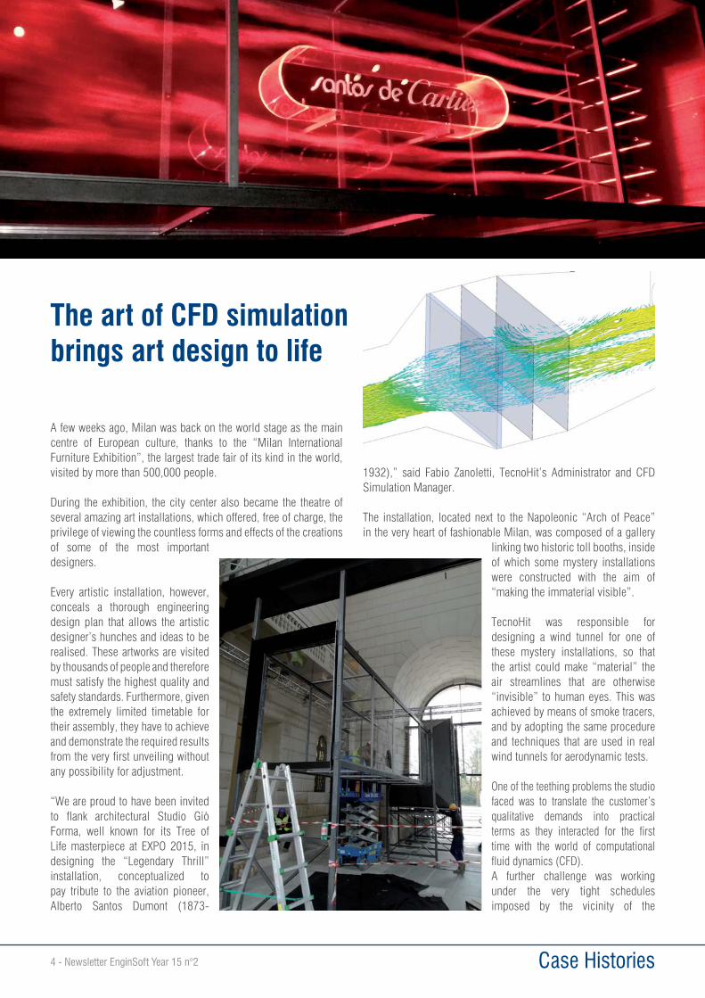
A few weeks ago, Milan was back on the world stage as the main centre of European culture, thanks to the “Milan International Furniture Exhibition”, the largest trade fair of its kind in the world, visited by more than 500,000 people.
During the exhibition, the city center also became the theatre of several amazing art installations, which offered, free of charge, the privilege of viewing the countless forms and effects of the creations of some of the most important designers.
Every artistic installation, however, conceals a thorough engineering design plan that allows the artistic designer’s hunches and ideas to be realised. These artworks are visited by thousands of people and therefore must satisfy the highest quality and safety standards. Furthermore, given the extremely limited timetable for their assembly, they have to achieve and demonstrate the required results from the very first unveiling without any possibility for adjustment.
“We are proud to have been invited to flank architectural Studio Giò Forma, well known for its Tree of Life masterpiece at EXPO 2015, in designing the “Legendary Thrill” installation, conceptualized to pay tribute to the aviation pioneer, Alberto Santos Dumont (1873-
1932),” said Fabio Zanoletti, TecnoHit’s Administrator and CFD Simulation Manager.
The installation, located next to the Napoleonic “Arch of Peace” in the very heart of fashionable Milan, was composed of a gallery
linking two historic toll booths, inside of which some mystery installations were constructed with the aim of “making the immaterial visible”.
TecnoHit was responsible for designing a wind tunnel for one of these mystery installations, so that the artist could make “material” the air streamlines that are otherwise “invisible” to human eyes. This was achieved by means of smoke tracers, and by adopting the same procedure and techniques that are used in real wind tunnels for aerodynamic tests.
One of the teething problems the studio faced was to translate the customer’s qualitative demands into practical terms as they interacted for the first time with the world of computational fluid dynamics (CFD).A further challenge was working under the very tight schedules imposed by the vicinity of the
The art of CFD simulation brings art design to life
Newsletter EnginSoft Year 15 n°2 - 5 Case Histories
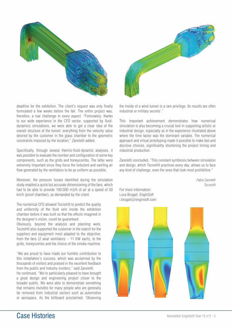
deadline for the exhibition. The client’s request was only finally formulated a few weeks before the fair. The entire project was, therefore, a real challenge in every aspect. “Fortunately, thanks to our wide experience in the CFD sector, supported by fluid-dynamics simulations, we were able to get a clear idea of the overall structure of the tunnel: everything from the velocity value desired by the customer in the glass chamber to the geometric constraints imposed by the location,” Zanoletti added.
Specifically, through several thermo-fluid-dynamic analyses, it was possible to evaluate the number and configuration of some key components, such as the grids and honeycombs. The latter were extremely important since they force the turbulent and swirling air flow generated by the ventilators to be as uniform as possible.
Moreover, the pressure losses identified during the simulation study enabled a quick but accurate dimensioning of the fans, which had to be able to provide 100,000 m3/h of air at a speed of 50 km/h (proof chamber), as demanded by the client.
The numerical CFD allowed TecnoHit to predict the quality and uniformity of the fluid vein inside the exhibition chamber before it was built so that the effects imagined in the designer’s vision, could be guaranteed.Obviously, beyond the analysis and planning work, TecnoHit also supported the customer in the search for the suppliers and equipment most adapted to the objective: from the fans (2 axial ventilators – 11 KW each), to the grids, honeycombs and the choice of the smoke machine.
“We are proud to have made our humble contribution to this installation’s success, which was acclaimed by the thousands of visitors and praised in the excellent feedback from the public and industry insiders,” said Zanoletti.He continued, “We’re particularly pleased to have brought a great design and engineering project closer to the broader public. We were able to demonstrate something that remains invisible for many people who are generally far removed from industrial sectors such as automotive or aerospace. As the billboard proclaimed: ‘Observing
the inside of a wind tunnel is a rare privilege. Its results are often industrial or military secrets’.”
This important achievement demonstrates how numerical simulation is also becoming a crucial tool in supporting artistic or industrial design, especially as in the experience illustrated above where the time factor was the dominant variable. The numerical approach and virtual prototyping made it possible to make fast and decisive choices, significantly shortening the project timing and industrial production.
Zanoletti concluded, “This constant symbiosis between simulation and design, which TecnoHit practices every day, allows us to face any kind of challenge, even the ones that look most prohibitive.”
Fabio ZanolettiTecnoHit
For more information:Luca Brugali, [email protected]
6 - Newsletter EnginSoft Year 15 n°2 Case Histories
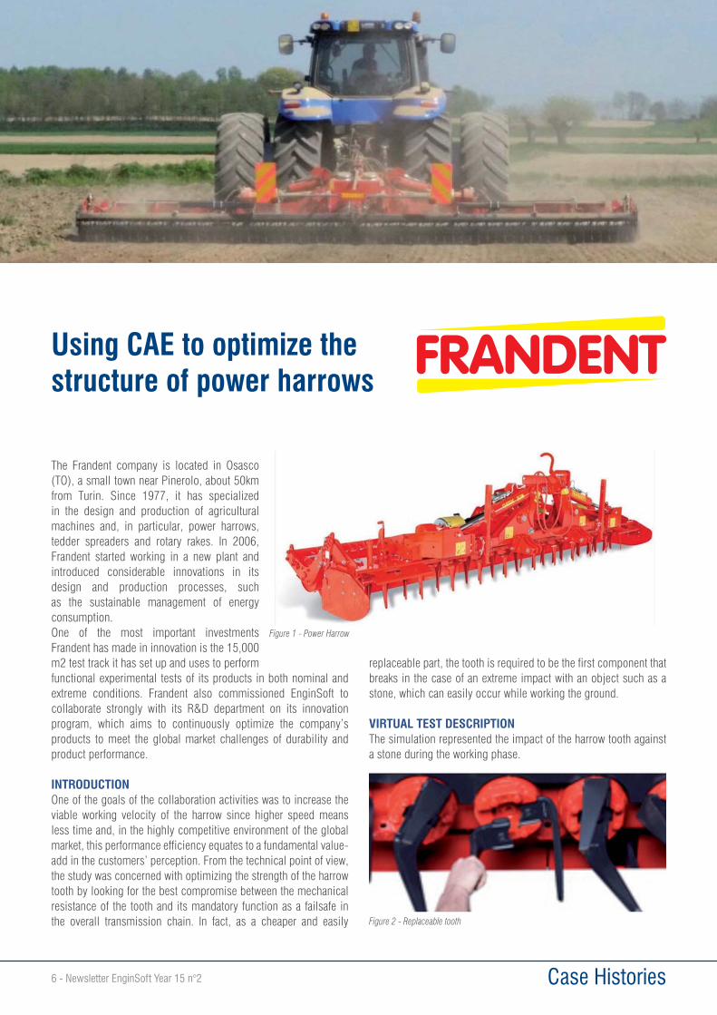
The Frandent company is located in Osasco (TO), a small town near Pinerolo, about 50km from Turin. Since 1977, it has specialized in the design and production of agricultural machines and, in particular, power harrows, tedder spreaders and rotary rakes. In 2006, Frandent started working in a new plant and introduced considerable innovations in its design and production processes, such as the sustainable management of energy consumption.One of the most important investments Frandent has made in innovation is the 15,000 m2 test track it has set up and uses to perform functional experimental tests of its products in both nominal and extreme conditions. Frandent also commissioned EnginSoft to collaborate strongly with its R&D department on its innovation program, which aims to continuously optimize the company’s products to meet the global market challenges of durability and product performance.
INTRODUCTIONOne of the goals of the collaboration activities was to increase the viable working velocity of the harrow since higher speed means less time and, in the highly competitive environment of the global market, this performance efficiency equates to a fundamental value-add in the customers’ perception. From the technical point of view, the study was concerned with optimizing the strength of the harrow tooth by looking for the best compromise between the mechanical resistance of the tooth and its mandatory function as a failsafe in the overall transmission chain. In fact, as a cheaper and easily
replaceable part, the tooth is required to be the first component that breaks in the case of an extreme impact with an object such as a stone, which can easily occur while working the ground.
VIRTUAL TEST DESCRIPTIONThe simulation represented the impact of the harrow tooth against a stone during the working phase.
Using CAE to optimize the structure of power harrows
Figure 1 - Power Harrow
Figure 2 - Replaceable tooth
Newsletter EnginSoft Year 15 n°2 - 7 Case Histories
The test was carried out in different conditions which varied:• the impact point;• the impact angle;• the stone shape;• the rotational and translation speeds
ratio;• the severity of the test (from nominal
conditions to the most severe scenario).
The impact velocity is the sum of the tractor’s forward translational speed and the tangential velocity of the tooth. Nominal operating speed was also analyzed. Moreover, two different geometries were considered:• A nominal geometry (corresponding to the CAD output);• The geometry of a worn tooth and tooth housing.
In order to facilitate the replacement of a broken tooth in the presence of dust and mud, each tooth is mounted with a clearance area.
These coupling conditions, however, also allow the surfaces to slide and impact against each other during use and, as a consequence, the clearance area increases during the life of the harrow. As a result, the mechanical behavior of the new and worn tooth geometries differs.
FINITE ELEMENT MODEL (FEM)The FEM was generated using second-order solid elements; in particular, the teeth of the harrow were modeled with tetrahedral elements. The initial conditions were introduced by considering the rigid motion of the support shaft.
In order to replicate the working conditions of the harrow, a foam material model with properties able to reproduce the real phenomena was used to represent the soil. The soil supports the stone at the opposite side with reference to the impact.
The steel constituting the tooth’s material was introduced as *MAT_24 through the stress/strain curves (considering the strain rate). To correctly simulate the failure behavior, the engineers implemented a homogenization algorithm. They also introduced and calibrated a nonlocal theory approach (material card *MAT_NONLOCAL); in this method, the failure criterion considers the
state of the material within a radius of influence surrounding the integration point.
An advantage of using nonlocal failure is that mesh size and mesh flow sensitivity on failure are greatly reduced which leads to results that converge to a unique solution as the mesh is refined. Without introducing a nonlocal criterion, strains will tend to localize randomly with mesh refinement, which leads to results that can change significantly from mesh to mesh.
A nonlocal failure theory approach can be very helpful in predicting both the onset and the evolution of the material failure. It renders the failure mesh independent, more homogeneous and more realistic. This method does, however, increase CPU time significantly, so it is wiser to use it strategically or for reduced areas.
RESULTSModel calibrationThe model calibration concerned two different aspects:• soil and stone modeling;• the calibration of nonlocal
material parameters
Initially, the working conditions analyzed were not critical and did not lead to tooth rupture; therefore, the soil and stone material models were modified to make the analysis more severe and realistic.
Figure 3 - Testing ring
Figure 6- Finite element model of the rotor
Figure 5 - The complete finite element model
Case Histories8 - Newsletter EnginSoft Year 15 n°2
The model had to represent:• similar conditions of failure to those in the experimental tests;• the initial crack’s position (where the crack starts);• the crack’s evolution.
The second correlation step was to set the nonlocal material parameters. The values introduced had to guarantee that the initial failure point and its evolution were not affected by:• the local mesh• the local mesh size• the local mesh orientation
As a result, the simulation team was able to create a correlated and robust FE model.
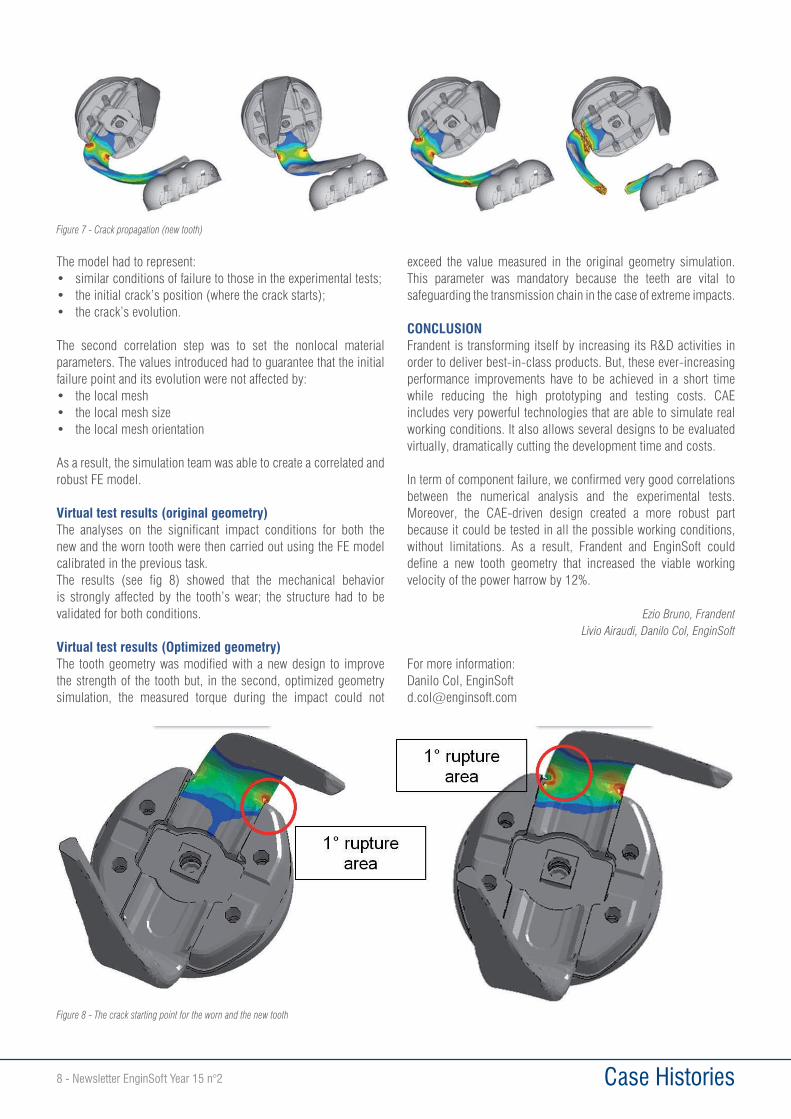
Virtual test results (original geometry)The analyses on the significant impact conditions for both the new and the worn tooth were then carried out using the FE model calibrated in the previous task.The results (see fig 8) showed that the mechanical behavior is strongly affected by the tooth’s wear; the structure had to be validated for both conditions.
Virtual test results (Optimized geometry)The tooth geometry was modified with a new design to improve the strength of the tooth but, in the second, optimized geometry simulation, the measured torque during the impact could not
exceed the value measured in the original geometry simulation. This parameter was mandatory because the teeth are vital to safeguarding the transmission chain in the case of extreme impacts.
CONCLUSIONFrandent is transforming itself by increasing its R&D activities in order to deliver best-in-class products. But, these ever-increasing performance improvements have to be achieved in a short time while reducing the high prototyping and testing costs. CAE includes very powerful technologies that are able to simulate real working conditions. It also allows several designs to be evaluated virtually, dramatically cutting the development time and costs.
In term of component failure, we confirmed very good correlations between the numerical analysis and the experimental tests. Moreover, the CAE-driven design created a more robust part because it could be tested in all the possible working conditions, without limitations. As a result, Frandent and EnginSoft could define a new tooth geometry that increased the viable working velocity of the power harrow by 12%.
Ezio Bruno, FrandentLivio Airaudi, Danilo Col, EnginSoft
For more information:Danilo Col, [email protected]
Figure 7 - Crack propagation (new tooth)
Figure 8 - The crack starting point for the worn and the new tooth
Newsletter EnginSoft Year 15 n°2 - 9 Case Histories
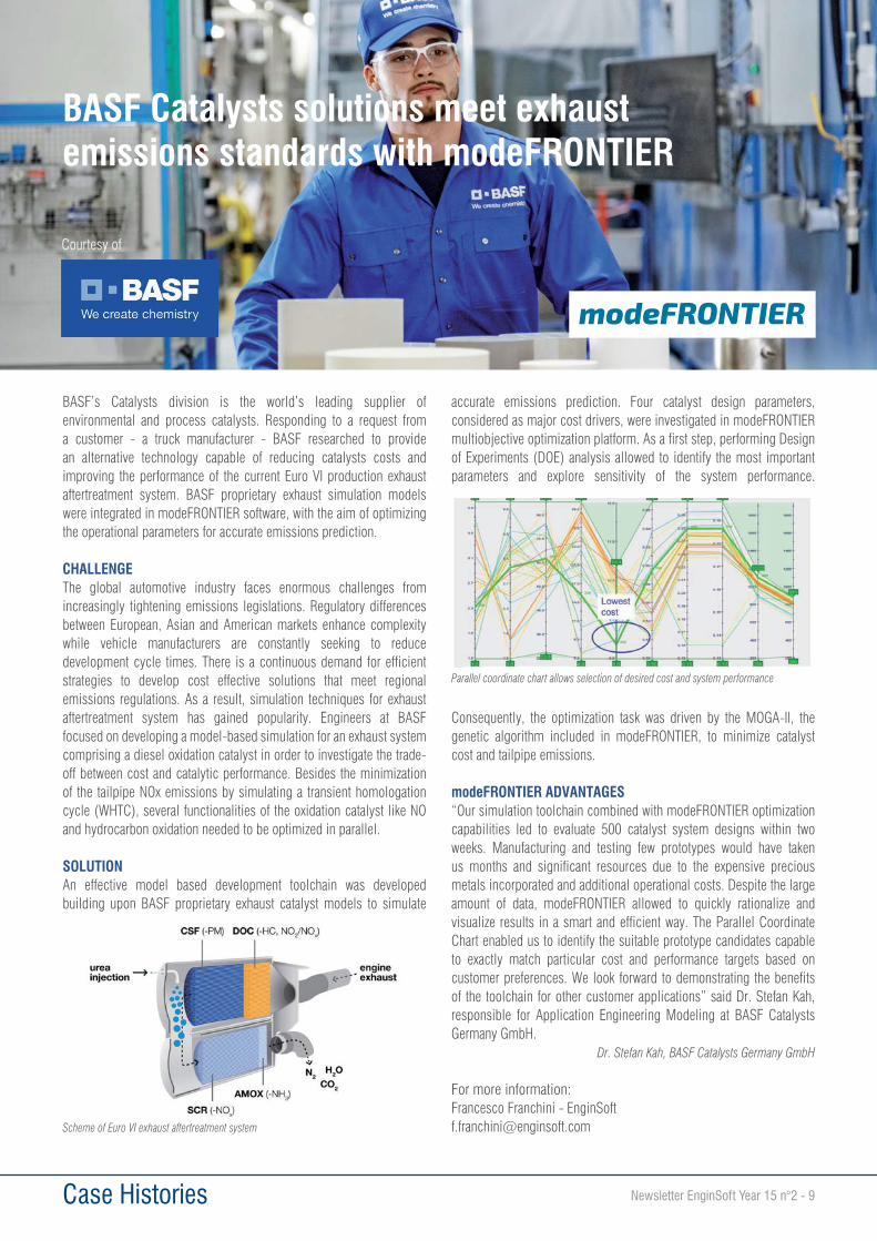
BASF’s Catalysts division is the world’s leading supplier of environmental and process catalysts. Responding to a request from a customer - a truck manufacturer - BASF researched to provide an alternative technology capable of reducing catalysts costs and improving the performance of the current Euro VI production exhaust aftertreatment system. BASF proprietary exhaust simulation models were integrated in modeFRONTIER software, with the aim of optimizing the operational parameters for accurate emissions prediction.
CHALLENGEThe global automotive industry faces enormous challenges from increasingly tightening emissions legislations. Regulatory differences between European, Asian and American markets enhance complexity while vehicle manufacturers are constantly seeking to reduce development cycle times. There is a continuous demand for efficient strategies to develop cost effective solutions that meet regional emissions regulations. As a result, simulation techniques for exhaust aftertreatment system has gained popularity. Engineers at BASF focused on developing a model-based simulation for an exhaust system comprising a diesel oxidation catalyst in order to investigate the trade-off between cost and catalytic performance. Besides the minimization of the tailpipe NOx emissions by simulating a transient homologation cycle (WHTC), several functionalities of the oxidation catalyst like NO and hydrocarbon oxidation needed to be optimized in parallel.
SOLUTIONAn effective model based development toolchain was developed building upon BASF proprietary exhaust catalyst models to simulate
accurate emissions prediction. Four catalyst design parameters, considered as major cost drivers, were investigated in modeFRONTIER multiobjective optimization platform. As a first step, performing Design of Experiments (DOE) analysis allowed to identify the most important parameters and explore sensitivity of the system performance.
Consequently, the optimization task was driven by the MOGA-II, the genetic algorithm included in modeFRONTIER, to minimize catalyst cost and tailpipe emissions.
modeFRONTIER ADVANTAGES“Our simulation toolchain combined with modeFRONTIER optimization capabilities led to evaluate 500 catalyst system designs within two weeks. Manufacturing and testing few prototypes would have taken us months and significant resources due to the expensive precious metals incorporated and additional operational costs. Despite the large amount of data, modeFRONTIER allowed to quickly rationalize and visualize results in a smart and efficient way. The Parallel Coordinate Chart enabled us to identify the suitable prototype candidates capable to exactly match particular cost and performance targets based on customer preferences. We look forward to demonstrating the benefits of the toolchain for other customer applications” said Dr. Stefan Kah, responsible for Application Engineering Modeling at BASF Catalysts Germany GmbH.
Dr. Stefan Kah, BASF Catalysts Germany GmbH
For more information:Francesco Franchini - [email protected]
Parallel coordinate chart allows selection of desired cost and system performance
Scheme of Euro VI exhaust aftertreatment system
BASF Catalysts solutions meet exhaustemissions standards with modeFRONTIER
Courtesy of

10 - Newsletter EnginSoft Year 15 n°2 Case Histories
Fire safety engineering and the performance-based design approach were introduced into Italian law in 2007. This article examines the use of Computational Fluid Dynamics (CFD) tools that could have a relevant impact on the design process, as this Condó road tunnel case study demonstrates.
TargetThe primary objectives of this study were to evaluate smoke propagation during a fire and its potential effect on tunnel evacuation. It was assumed that a fire was caused by a passenger vehicle near the only emergency exit, where no smoke detectors are installed. The calculations were performed using Fire Dynamic Simulator (FDS) + Evac.
AnalysisThe Condó road tunnel’s real geometry and the HVAC system were modelled with maximum accuracy in relation to the physics of the problem and included a sensitive analysis that had been performed in a previous study on the same tunnel. The fire design was defined through the coupling of theoretical relationships and experimental data.
Using CAE to support fire safety engineering in the Condó road tunnel
An important role for numerical simulation in risk management
Distribution of physical characteristics in the occupant population
The lifecycle of modern critical infrastructures and their interconnections and dependences pose increasing challenges to engineers faced with the task of ensuring the safety of users, the integrity of assets and the continuity of businesses.Each planned activity for protection, safety and resilience implies a deep knowledge of the “behaviors” of critical infrastructures and complex systems during disruptions, catastrophic events or industrial accidents. Such knowledge is necessary to optimise resources, avoid loss of investments and to maximise the impact of the efforts deployed.For all these reasons, modern techniques such as computer-aided numerical simulations are now being used to support and further reinforce consolidated practices in risk management. The possibility to analyse and predict expected behaviours - and to hard-code them alongside the archive of direct human experiences - will prove to be a game-changer in a resilient approach to the management of critical infrastructures. Examples like the one covered by the study below, performed by means of Fire Dynamic Simulator (FDS) and Evac, clearly show where and how the design of buildings and infrastructure could be improved to avoid the negative consequences from accidents or disruptions.One could also envisage the coupling of risk assessment techniques with simulations to do Simulation-based Risk Assessments (SBRS) and Dynamic Risk Analysis using sensors and specifically trained cognitive systems to run live simulations and provide early warnings.
Dott. Alessandro Lazari, PhDContact Agent at Space, Security and Migration’s Unit
European Commission – JRC
Newsletter EnginSoft Year 15 n°2 - 11 Case Histories
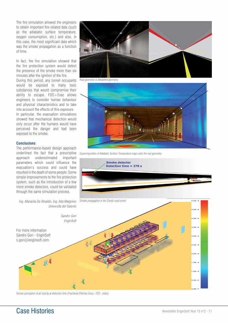
The fire simulation allowed the engineers to obtain important fire-related data (such as the adiabatic surface temperature, oxygen consumption, etc.) and also, in this case, the most significant data which was the smoke propagation as a function of time.
In fact, the fire simulation showed that the fire protection system would detect the presence of the smoke more than six minutes after the ignition of the fire.During this period, any tunnel occupants would be exposed to many toxic substances that would compromise their ability to escape. FDS+Evac allows engineers to consider human behaviour and physical characteristics and to take into account the effects of this exposure.In particular, the evacuation simulations showed that mechanical detection would only occur after the humans would have perceived the danger and had been exposed to the smoke.
ConclusionsThe performance-based design approach underlined the fact that a prescriptive approach underestimated important parameters which could influence the evacuation’s success and could have resulted in the death of some people. Some simple improvements to the fire protection system, such as the introduction of a few more smoke detectors, could be validated through the same simulation process.
Ing. Mariarita De Rinaldis, Ing. Ada Malgnino Università del Salento
Sandro GoriEnginSoft
For more informationSandro Gori - [email protected]
Real geometry vs Modelled geometry
Smoke propagation in the Condó road tunnel
Superimposition of Adiabatic Surface Temperature maps onto the real geometry
Human perception of air toxicity at detection time (Fractional Effective Dose - FED - index)

12 - Newsletter EnginSoft Year 15 n°2 Case Histories
Since its inception, the forging process could only be mastered by means of its operator’s know-how due to its intrinsic difficulties. A trial-and-error approach -- with all its related drawbacks -- was the only way to measure the feasibility of a hot-forging process. In recent years, however, the development of specific finite element method (FEM) codes to simulate these kinds of manufacturing processes (eg. FORGE, developed by Transvalor S.A. and distributed in Italy by EnginSoft) led to the wider sharing of knowledge, the extension of forging capabilities, and the optimization of existing processes. In 2018, two years since the beginning of its collaboration with EnginSoft which also saw the introduction of FORGE to its production development workflow, OMFA Inox has decided to publish the main benefits it gained from these decisions. First founded in 1971 by Lidio Ballan and his father Emilio, in 1974 OMFA began the hot forging of stainless (austenitic, ferritic, martensitic, duplex) steels and nickel alloys, and this is now its core business. The company’s production output varies from some hundreds to approximately 10,000 parts per batch as a function of product and customers. It produces both normed and on-requirement forged parts for the food, chemical, oil and gas, and automotive markets, with more than 50% of its production going to export. One of its main strengths is its ability to produce forged parts with very reduced machining allowances, resulting in less machining operations and material usage. Its production equipment is composed of four forging lines (400-, 1 000-, 1 600- and 2 500 ton) each with an induction furnace.
Using numerical simulation to optimize productionUntil recently, OMFA focused its production on axisymmetric parts (eg. flanges). By using FORGE to conduct numerical evaluations of several scenarios, the company was able to determine the geometrical parameters influencing the quality of its final parts, which are a constant for almost all its production. The understanding acquired from these numerical simulations enabled the supervisors to modify the dies for the production line and speed up the optimization process without needing to involve the technical office.
The geometrical parameters identified were (Fig.1):• H_B: the height of the central part
of the lower die;• S_F: the thickness of the central
flash. The H_B/S_F ratio strongly influences the filling of the die cavity and the creation of material folds in the central area of the part being produced;
• S_B: the thickness of the outer flash. This value strongly influences the process: the lower the thickness, the higher the required force (and the elastic deformation of the press); the higher the thickness, the higher the material usage; and
• S_S: the draft angle of the central area of the upper die. Together with H_B, this parameter allows operators to manage the flow speed of materials during backward extrusion die filling.
As the authors anticipated in the article published in edition 4 of the EnginSoft Newsletter in 2016, and also presented at the 32nd International CAE Conference (http://proceedings2016.caeconference.com/forming.html), one of OMFA’s first achievements after it introduced FORGE in 2016 was to understand and resolve the issue of hot tears on parts. The evaluation of these geometrical parameters was paramount to achieving substantial improvements in this area.
Some specific examples related to the improvements achieved are reported below:• Fig.2a: the elimination of the flash generated by forging (OMFA
reduced material usage by 7%, from 1.81 kg to 1.68 kg on the initial billet)
• Fig.2b: the redesign of the machining allowances and the elimination of the flash (to achieve a total reduction of 10% on material usage, from 1.635 kg to 1.472 kg on the initial billet) [the final part is shown in green, the old forged part in red, and the optimized forged part in black];
• Fig.2c: the redesign of the machining allowances and the elimination of the flash (to achieve a total reduction of 3.5% on material usage, from 0.77 kg to 0.743 kg on the initial billet); the redesign of the dies to reduce/eliminate hot tears on the final part (note the differences between the old case, above, and the optimized one, below, with regard to the damage risk, based on the Latham-Cockroft criteria)
Simulating hot forging processes: moving from practical experience into new markets
Figure 1 - Geometrical parameters influencing the quality of the part Figure 2 - Improvements in material usage and part quality
a)
b)c)
Newsletter EnginSoft Year 15 n°2 - 13 Case Histories
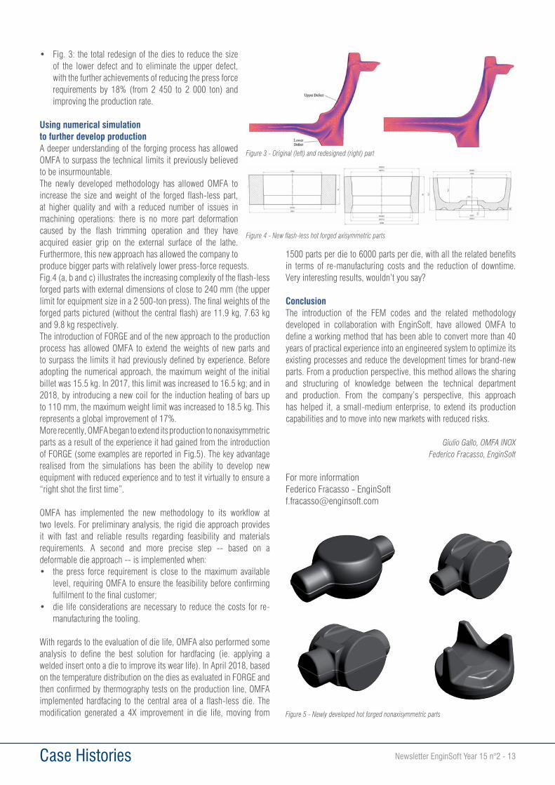
• Fig. 3: the total redesign of the dies to reduce the size of the lower defect and to eliminate the upper defect, with the further achievements of reducing the press force requirements by 18% (from 2 450 to 2 000 ton) and improving the production rate.
Using numerical simulation to further develop productionA deeper understanding of the forging process has allowed OMFA to surpass the technical limits it previously believed to be insurmountable.The newly developed methodology has allowed OMFA to increase the size and weight of the forged flash-less part, at higher quality and with a reduced number of issues in machining operations: there is no more part deformation caused by the flash trimming operation and they have acquired easier grip on the external surface of the lathe. Furthermore, this new approach has allowed the company to produce bigger parts with relatively lower press-force requests.Fig.4 (a, b and c) illustrates the increasing complexity of the flash-less forged parts with external dimensions of close to 240 mm (the upper limit for equipment size in a 2 500-ton press). The final weights of the forged parts pictured (without the central flash) are 11.9 kg, 7.63 kg and 9.8 kg respectively.The introduction of FORGE and of the new approach to the production process has allowed OMFA to extend the weights of new parts and to surpass the limits it had previously defined by experience. Before adopting the numerical approach, the maximum weight of the initial billet was 15.5 kg. In 2017, this limit was increased to 16.5 kg; and in 2018, by introducing a new coil for the induction heating of bars up to 110 mm, the maximum weight limit was increased to 18.5 kg. This represents a global improvement of 17%.More recently, OMFA began to extend its production to nonaxisymmetric parts as a result of the experience it had gained from the introduction of FORGE (some examples are reported in Fig.5). The key advantage realised from the simulations has been the ability to develop new equipment with reduced experience and to test it virtually to ensure a “right shot the first time”.
OMFA has implemented the new methodology to its workflow at two levels. For preliminary analysis, the rigid die approach provides it with fast and reliable results regarding feasibility and materials requirements. A second and more precise step -- based on a deformable die approach -- is implemented when:• the press force requirement is close to the maximum available
level, requiring OMFA to ensure the feasibility before confirming fulfilment to the final customer;
• die life considerations are necessary to reduce the costs for re-manufacturing the tooling.
With regards to the evaluation of die life, OMFA also performed some analysis to define the best solution for hardfacing (ie. applying a welded insert onto a die to improve its wear life). In April 2018, based on the temperature distribution on the dies as evaluated in FORGE and then confirmed by thermography tests on the production line, OMFA implemented hardfacing to the central area of a flash-less die. The modification generated a 4X improvement in die life, moving from
1500 parts per die to 6000 parts per die, with all the related benefits in terms of re-manufacturing costs and the reduction of downtime. Very interesting results, wouldn’t you say?
ConclusionThe introduction of the FEM codes and the related methodology developed in collaboration with EnginSoft, have allowed OMFA to define a working method that has been able to convert more than 40 years of practical experience into an engineered system to optimize its existing processes and reduce the development times for brand-new parts. From a production perspective, this method allows the sharing and structuring of knowledge between the technical department and production. From the company’s perspective, this approach has helped it, a small-medium enterprise, to extend its production capabilities and to move into new markets with reduced risks.
Giulio Gallo, OMFA INOXFederico Fracasso, EnginSoft
For more informationFederico Fracasso - [email protected]
Figure 3 - Original (left) and redesigned (right) part
Figure 4 - New flash-less hot forged axisymmetric parts
Figure 5 - Newly developed hot forged nonaxisymmetric parts
14 - Newsletter EnginSoft Year 15 n°2 Case Histories
The calibration of numerical models based on experimental data is a fundamental activity for analysts and designers. Oftentimes, it is the only way to ensure that the numerical behavior predicted by the model is accurate and that the calculated results are reliable and can be used for further steps of model-based design.At the same time, though, the calibration process can be very time consuming and complex to perform. This is particularly true when there is a high number of input variables and when the numerical model represents a highly nonlinear problem. When manually dealing with these kinds of problems, tuning the parameters of the model to match the numerical data becomes almost impossible. At the same time, it is impracticable to perform a full design of experiments (DOE) to automatically explore the entire design space to select the best set of parameters.
Consequently, the most efficient way to perform this kind of calibration is to use an optimization program to drive the simulations. In this article we describe how we used this approach: we automatically performed the calibration of two multibody models developed using RecurDyn by exploiting the optimization algorithms provided in modeFRONTIER.
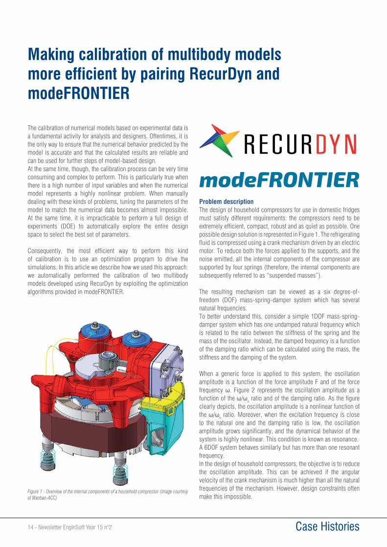
Problem descriptionThe design of household compressors for use in domestic fridges must satisfy different requirements: the compressors need to be extremely efficient, compact, robust and as quiet as possible. One possible design solution is represented in Figure 1. The refrigerating fluid is compressed using a crank mechanism driven by an electric motor. To reduce both the forces applied to the supports, and the noise emitted, all the internal components of the compressor are supported by four springs (therefore, the internal components are subsequently referred to as “suspended masses”).
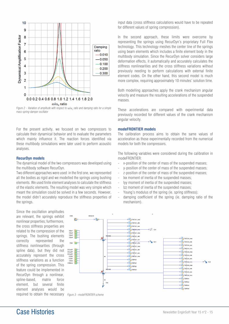
The resulting mechanism can be viewed as a six degree-of-freedom (DOF) mass-spring-damper system which has several natural frequencies.To better understand this, consider a simple 1DOF mass-spring-damper system which has one undamped natural frequency which is related to the ratio between the stiffness of the spring and the mass of the oscillator. Instead, the damped frequency is a function of the damping ratio which can be calculated using the mass, the stiffness and the damping of the system.
When a generic force is applied to this system, the oscillation amplitude is a function of the force amplitude F and of the force frequency . Figure 2 represents the oscillation amplitude as a function of the / n ratio and of the damping ratio. As the figure clearly depicts, the oscillation amplitude is a nonlinear function of the / n ratio. Moreover, when the excitation frequency is close to the natural one and the damping ratio is low, the oscillation amplitude grows significantly, and the dynamical behavior of the system is highly nonlinear. This condition is known as resonance.A 6DOF system behaves similarly but has more than one resonant frequency.In the design of household compressors, the objective is to reduce the oscillation amplitude. This can be achieved if the angular velocity of the crank mechanism is much higher than all the natural frequencies of the mechanism. However, design constraints often make this impossible.
Making calibration of multibody models more efficient by pairing RecurDyn and modeFRONTIER
Figure 1 - Overview of the internal components of a household compressor (image courtesy of Wanbao-ACC)
Newsletter EnginSoft Year 15 n°2 - 15 Case Histories
For the present activity, we focused on two compressors to calculate their dynamical behavior and to evaluate the parameters which mainly influence it. The reaction forces identified via these multibody simulations were later used to perform acoustic analyses.
RecurDyn modelsThe dynamical model of the two compressors was developed using the multibody software RecurDyn.Two different approaches were used: in the first one, we represented all the bodies as rigid and we modelled the springs using bushing elements. We used finite element analyses to calculate the stiffness of the elastic elements. The resulting model was very simple which meant the simulation could be solved in a few seconds. However, the model didn’t accurately reproduce the stiffness properties of the springs.
Since the oscillation amplitudes are relevant, the springs exhibit nonlinear properties; furthermore, the cross stiffness properties are related to the compression of the springs. The bushing elements correctly represented the stiffness nonlinearities (through spline data), but they did not accurately represent the cross stiffness variations as a function of the spring compression. This feature could be implemented in RecurDyn through a nonlinear, spline-based, matrix force element, but several finite element analyses would be required to obtain the necessary
input data (cross stiffness calculations would have to be repeated for different values of spring compression).
In the second approach, these limits were overcome by representing the springs using RecurDyn’s proprietary Full Flex technology. This technology meshes the center line of the springs using beam elements which includes a finite element body in the multibody simulation. Since the RecurDyn solver considers large deformation effects, it automatically and accurately calculates the stiffness nonlinearities and the cross stiffness variations without previously needing to perform calculations with external finite element codes. On the other hand, this second model is much more complex, requiring approximately 10 minutes’ solution time.
Both modelling approaches apply the crank mechanism angular velocity and measure the resulting accelerations of the suspended masses.
These accelerations are compared with experimental data previously recorded for different values of the crank mechanism angular velocity.
modeFRONTIER modelsThe calibration process aims to obtain the same values of acceleration as those experimentally recorded from the numerical models for both the compressors.
The following variables were considered during the calibration in modeFRONTIER:- x-position of the center of mass of the suspended masses;- y-position of the center of mass of the suspended masses;- z-position of the center of mass of the suspended masses;- Ixx moment of inertia of the suspended masses;- Iyy moment of inertia of the suspended masses;- Izz moment of inertia of the suspended masses;- Young’s modulus of the spring (ie. spring stiffness);- damping coefficient of the spring (ie. damping ratio of the
mechanism).
Figure 2 – Variation of amplitude with respect to / n ratio and damping ratio for a simple mass-spring-damper oscillator
Figure 3 - modeFRONTIER scheme

16 - Newsletter EnginSoft Year 15 n°2 Case Histories
The variables were chosen based on the following considerations:1) the 3D CAD does not accurately reproduce the inertial properties
of the suspended masses because some components are missing and others (such as the electric motor windings) are simplified;
2) the spring properties have a statistical distribution due to the realization process.
We considered the accelerations for two values of crank angular velocities as objectives: one close to the resonance frequency and the other far from it.
The number of input variables and objectives was significant, so the number of simulations required to minimize the error between the numerical and experimental accelerations was very high. Considering that two multibody simulations (one for each angular velocity) would have had to be performed for each set of parameters, the optimization process would have required days.
For this reason, we decided to pair two modeling approaches: firstly, we used the approach with rigid bodies and bushings in order to quickly perform a large number of simulations. This process was driven automatically by modeFRONTIER which used the space fillers algorithm to generate a pool of initial samples. Based on these points, we later used the Multi Objective Genetic Algorithm II (MOGA-II) to drive the optimization process.
The first set of results contained thousands of data points obtained with the bushings model. These were used to:1) evaluate which input variables had more influence on the
outputs;2) reduce the variation interval of the input variables based on the
obtained results.
Once we had reduced the number of input variables and their variation interval, we used the second modelling approach and performed a second optimization process using modeFRONTIER. Since this modeling scheme required much more CPU time, we
only performed a few hundred simulations, yet these were sufficient to obtain an optimal set of parameters -- thanks to the simulations we had performed previously using the simplified model.
The pairing of RecurDyn and modeFRONTIER proved to be an efficient way to calibrate multibody models with a high number of input variables and highly nonlinear behavior. The features available in RecurDyn allow the user to create both simplified and extremely accurate models which can be used sequentially to reduce the overall calibration time.
The algorithms used in modeFRONTIER drive the optimization easily and successfully, making it an essential tool for complex problems in which manual calibration would be impossible.
Davide Marini, EnginSoft
For more information: Fabiano Maggio - [email protected]
Figure 4 - Scatter point data representing the results obtained with the second modeling approach (Full Flex springs)
Workshop: planning and negotiating with metal suppliers
EnginSoft is proud to announce a new event targeting all companies that make use of supplies sourced from foundries or metal forming companies. The seminar will take place at the 34th International CAE Conference, scheduled to take place at the Vicenza exhibition centre from 8 to 9 October 2018.
Manufacturability and quality control are essential prerogatives in the design phase of a component. Consequently, the prevention of design flaws that may have a detrimental effect on the production of the component, and the ability to constructively negotiate with suppliers are key capabilities for modern companies that increasingly strive for innovation and product quality.
The three-hour workshop will illustrate the dynamics of the foundry and metal forming production processes, as well as some integrated design and optimization techniques targeted at the realization of a component according to its technical specifications. The seminar is aimed at Technical Managers, R&D Managers, Supply Chain Managers and Quality Managers.
For more information, or to book for the seminar, contact: Giampiero Scarpa, EnginSoft - [email protected]
Newsletter EnginSoft Year 15 n°2 - 17 Case Histories
In the last years, lots of efforts have been made in the direction of a massive implementation of light alloys in several application fields, from the aerospace to the automotive industries [1]. Within the big family of light materials, the Aluminum (Al) alloys gained big importance in the last period thanks to their low weight-to-strength ratio and corrosion resistance, two fundamental properties in the direction of the reduction of masses and harmful emissions. The abovementioned qualities of Al alloys are partially counterbalanced by a limited formability at room temperature: it means that processing the material by means of conventional/innovative stamping processes in cold conditions still remains too critical. On the other hand, lots of studies are reported in literature about the positive effect of an increased working temperature to exploit the enhanced formability of the Al alloys: in such a way, more complex components can be thus successfully manufactured in one-step processing [2, 3]. Moreover, the manufacturing processes are no more designed following the too time-consuming trial-and-error approach: the numerical approach based on Finite Element (FE) simulations becomes undoubtedly a viable solution and, sometimes, an unavoidable step due to the large number of parameters involved in a specific manufacturing process. One of the key aspects in the construction of a robust and reliable FE model is a proper modelling of the material behaviour: in particular, if the process to be numerically simulated has to be carried out also in warm conditions, it becomes necessary to implement a suitable constitutive equation comprehensive of both the effect of the temperature and the strain rate on the mechanical behavior of the alloy under investigation. Literature reports several examples of constitutive models able to describe the mechanical behavior as a function of the strain rate, such as the ones provided by Johnson-Cook or by Zerilli-Armstrong.
It is also reported that the Zerilli-Armstrong model proves to be suitable for FCC materials, but underestimates the strength of BCC materials. In the present report, the attention has been focused on the Cowper-Symonds (CS) constitutive model [6]. According to its formulation, the dynamic equivalent stress, i.e. the equivalent stress at a strain rate level ( ) different from the reference one and indicated as d ) in Equation 1, is obtained from a reference flow stress curve ( r) multiplied by a factor that is a function of two parameters (D and p).
(1)
The experimental dataThe AA5754 alloy belongs to the group of the strain-hardenable Al alloys, i.e. the variation of its mechanical properties can be achieved only by means of plastic deformation. The AA5754 alloy has been experimentally characterized by means of tensile tests carried out at different temperature (150, 200 and 250°C) and strain rates (0.001,
Evaluation of the optimization algorithm performance on the calibration of the Cowper-Symonds analytical model for a strain-hardenable Al alloy
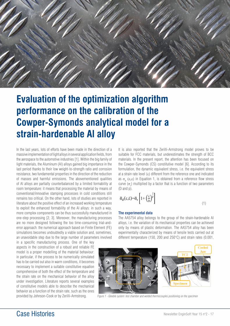
Figure 1 - Gleeble system: test chamber and welded thermocouples positioning on the specimen
18 - Newsletter EnginSoft Year 15 n°2 Case Histories
0.01, 0.1 s-1) levels. Tensile tests were carried out on the Gleeble system 3180 physical simulator available in the “Physical simulation of technological processes” laboratory in the Department of Mechanics, Mathematics and Management of the Politecnico di Bari. The Gleeble system, once a stable high vacuum condition inside the test chamber is reached, heats up the tensile specimen by Joule effect due to the flow of a controlled current, that is modulated in feedback mode according to the temperature acquisition of a “pilot” thermocouple welded (TC2 in Figure 1) in the middle region of the specimen.
The modeFRONTIER workflowAccording to Equation 1, for the calibration of the CS model, it is necessary to define a reference flow stress curve (expressed by the term r) and to evaluate the two material parameters D and p. It is also clear that the CS model is not temperature sensitive, thus it is necessary to evaluate the two unknown parameters for each of the tested temperature levels. The reference flow stress curve has been considered the one at the lowest tested strain rate level (i.e. 0.001 s-1) and initially fitted by means of the Ludwik power law A+B n. The dynamic equivalent stress is calculated by multiplying the reference flow curve by means of a quantity expressed by the brackets in Equation 1. The analytical curves, at the two other tested strain rate levels, are then compared with the experimental ones and an error function is calculated. The final aim is to minimize the mismatch between the curves thus defining the optimal value of the D and p parameters. A simple modeFRONTIER workflow has been built up, as shown in Figure 2.
The two input parameters are directly linked with an integrated Excel node: once D and p are defined at the beginning of each optimization step, their values are substituted in the worksheet and the analytical curves at the other two strain rate levels are thus calculated. For each curve an error parameter, describing the mismatch between the analytical and the experimental flow stress curve, is calculated according to Equation 2a and Equation 2b.
Where exp and calc refer respectively to the experimental and calculated equivalent stress for the same level of strain. The sum of the two error parameters represents the output variable ErrTot (see Equation 2c) that has to be minimized (objective function Min_ErrTot in Figure 2).
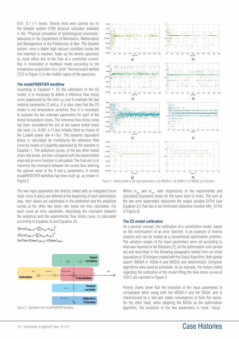
The CS model calibrationAs a general concept, the calibration of a constitutive model, based on the minimization of an error function, is an example of inverse analysis and can be treated as a conventional optimization problem. The variation ranges of the input parameters were set according to what was reported in the literature [7]; all the optimization runs carried out and described in the following paragraphs started from an initial population of 10 designs created with the Sobol Algorithm. Both global search (MOGA-II, NSGA-II and MOSA) and deterministic (Simplex) algorithms were used as scheduler. As an example, the history charts regarding the calibration of the model fitting the flow stress curves at 150°C are reported in Figure 3.
History charts show that the evolution of the input parameters is comparable when using both the MOGA-II and the NSGA, and is characterized by a fast and stable convergence of both the inputs. On the other hand, when adopting the MOSA as the optimization algorithm, the evolution of the two parameters is more “noisy”, Figure 2 - Overview of the modeFRONTIER workflow
Figure 3 - History charts of the input parameters: a-b) MOGA-II, c-d) NSGA-II, e-f) MOSA, g-h) Simplex
Newsletter EnginSoft Year 15 n°2 - 19 Case Histories
characterized by a systematic oscillation around a possible optimal value. The Simplex algorithm, even though clearly characterized by a faster convergence, shows a final stable value only for the D parameter while the evolution of p oscillates around a value of 11. To evaluate the accuracy of the abovementioned global search algorithms, a second optimization was run adopting the best design coming from the MOGA-II as a single individual DoE population and with two different gradient-based formulations (the SQP and the B-BFGS) as scheduler. The best designs, i.e. the individuals characterized by the lowest value of the ErrTot output variable, coming from the several investigated optimization routes are summarized and reported in Table 1.
The results in Table 1 suggest that, when a single optimization step was considered, the best design was characterized by similar optimal values of the input parameters, regardless of the specific algorithm considered (the only difference between the different algorithms can be found in the number of evaluated designs to get the final convergence). In addition, the MOGA-II algorithms proved to be highly accurate in predicting the optimal input parameter values, since the subsequent gradient-based step (both adopting the SQP and the B-BFGS) confirmed the initial guess.
Discussion of resultsA possible approach for the calibration of the well-known constitutive model proposed by Cowper and Symonds by means of a simple modeFRONTIER workflow has been presented. The basic idea is the evaluation of the unknown material parameters (D and p) by means of an inverse analysis, minimizing the error between the experimental flow stress curves coming from tensile tests and the analytical ones: in such a way, the inverse analysis approach can be treated as a conventional optimization problem in which the final aim is the minimization of an error function. The investigated model is not temperature sensitive, so the approach was repeated for each of the tested temperatures (150, 200 and 250°C). As reported in literature, the two model parameters (D and p) decrease by several orders of magnitude as the temperature increases [7]. The performance of heuristic (NGSA-II, MOGA-II, MOSA) and deterministic (Simplex) algorithms has been investigated: in accordance with the theory, the Simplex formulation reached the optimal value faster than the other tested global search algorithms. In addition, to evaluate their accuracy, a subsequent optimization run was
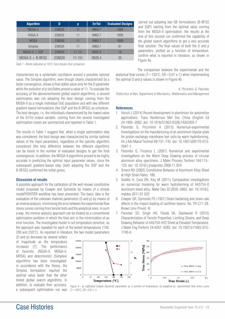
carried out adopting two GB formulations (B-BFGS and SQP) starting from the optimal value coming from the MOGA-II optimization: the results at the end of this second run confirmed the capability of the global search algorithms to get a very accurate final solution. The final values of both the D and p parameters, plotted as a function of temperature, confirm what is reported in literature, as shown in Figure 4a.
The comparison between the experimental and the analytical flow curves (T=150°C, SR=0.01 s-1) when implementing the optimal D and p values is shown in Figure 4b.
A. Piccininni, G. PalumboPolitecnico di Bari, Department of Mechanics, Mathematics and Management
References1. Hirsch J (2014) Recent development in aluminium for automotive
applications. Trans Nonferrous Met Soc China (English Ed 24:1995–2002. doi: 10.1016/S1003-6326(14)63305-7
2. Palumbo G, Piccininni A (2013) Numerical-experimental investigations on the manufacturing of an aluminium bipolar plate for proton exchange membrane fuel cells by warm hydroforming. Int J Adv Manuf Technol 69:731–742. doi: 10.1007/s00170-013-5047-1
3. Palumbo G, Tricarico L (2007) Numerical and experimental investigations on the Warm Deep Drawing process of circular aluminum alloy specimens. J Mater Process Technol 184:115–123. doi: 10.1016/j.jmatprotec.2006.11.024
4. Smerd RO (2005) Constitutive Behavior of Aluminum Alloy Sheet at High Strain Rates. 186.
5. Gedikli H, Cora ÖN, Koç M (2011) Comparative investigations on numerical modeling for warm hydroforming of AA5754-O aluminum sheet alloy. Mater Des 32:2650–2662. doi: 10.1016/j.matdes.2011.01.025
6. Cowper GR, Symonds PS (1957) Strain hardening and strain-rate effects in the impact loading of cantiliver beams. No. TR-C11-28. Brown Univ Provid. Ri
7. Panicker SS, Singh HG, Panda SK, Dashwood R (2015) Characterization of Tensile Properties, Limiting Strains, and Deep Drawing Behavior of AA5754-H22 Sheet at Elevated Temperature. J Mater Eng Perform 24:4267–4282. doi: 10.1007/s11665-015-1740-6
Algorithm D p ErrTot Evaluated Designs
MOGA-II 238020 11 9960.7 1000
NSGA-II 238020 11 9960.7 1000
MOSA 238040 11 9960.7 1000
Simplex 238020 11 9960.7 81
MOGA-II + SQP 238020 11.151 9926.4 16
MOGA-II + B-BFGS 238020 11.151 9926.4 35
Table 1 - Model calibration at 150°C: best designs final comparison
Figure 4 - a) calibrated Cowper-Symonds parameters as a function of temperature, b) analytical vs. experimental flow stress curve (T=150°C, SR=0.01 s-1)

20 - Newsletter EnginSoft Year 15 n°2 Case Histories
The TechNet Alliance, a network of Computer Aided Engineering (CAE) experts founded 30 years ago by the principal global ANSYS Channel Partners, brought together participants from 27 different countries for its Spring meeting in April 2018 in Berlin. The event, which was held from 19 to 21 April, offered attendees from numerous industry stakeholder perspectives the opportunity to present case studies, explore new software solutions and better understand the challenges posed when practically implementing CAE technologies. Participants included the Principal Members (companies that offer engineering simulation services and CAE technologies and software), simulation-driven product development companies, and renowned scientists, professors and engineers from universities and research institutes. The agenda focused not only on the strategic vision and the specific contribution that elite Channel partners can make to improving the functionality and the diffusion of ANSYS products, but also on all the different applications that can be developed both in physical terms (methodological processes and technologies) and for different organizations, environments and industry sectors. The first part of the meeting featured the contributions of Bob Thibeault, director of Woldwide Channel Business Development and other ANSYS Inc colleagues who, in describing program and product developments, opened the discussion on the latest market trends and their consequences for customer expectations. The second part of the event was characterized by diverse presentations and contributions that addressed various themes, applications and topics of current interest. The predictive simulation of complex coupled problems, additive manufacturing simulation,
high performance computing, and digital twins are just some of the subjects that were addressed. In particular, the presentation by ASAP Electronics GmbH on Virtual Vehicle Development and Methods for Virtual Sensors and Functional Safety, demonstrated the significant value of combining physical data with virtual prediction. Another important presentation addressed the development of Multi-Physics meta-models, based on RecurDyn, which enable engineers to create digital twins of dynamic systems. Last but not least, the presentation by Prof. Yaroslav Sergeyev, which has received several international research prizes (the Khwarizmi International Award, the Pythagoras International Prize in Mathematics, EUROPT Fellow, etc.), on “Infinity Computer and Numerical Computations with Infinities and Infinitesimals” demonstrated that concepts, forms and numerical systems -- which may seem to only be mathematical concepts -- offer the potential for new computational approaches, such as in the “Computer system for storing infinite, infinitesimal, and finite quantities and executing arithmetical operations with them” patented in US and EU.
The 37th TechNet Alliance Meeting confirms the network’s central role in the global ANSYS environment
(1)
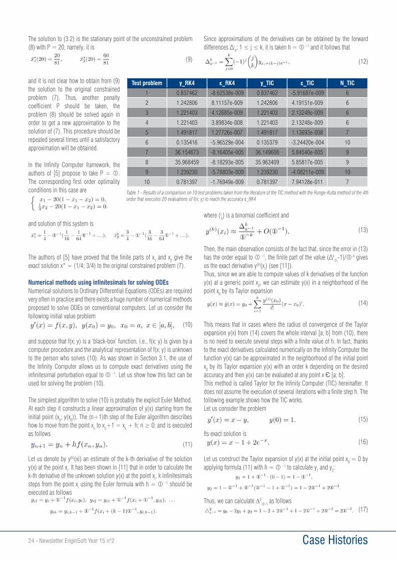
Newsletter EnginSoft Year 15 n°2 - 21 Case Histories
This article shows how it is possible to develop a new point of view on infinity and infinitesimals that not only changes our perception of these mathematical objects but gives the possibility to execute practical floating-point computations with a variety of infinities and infinitesimals on the Infinity Computer patented in EU and USA.In order to start let us recall that a numeral is a symbol or group of symbols that expresses a number being a concept. The same number can be represented by different numerals (e.g., the symbols ‘7’ and ‘VII’ are different numerals, but they represent the same number). Notice that different numeral systems can express different sets of numbers. For instance, the Roman system is not able to express zero and negative numbers. As a result, expressions V-V and V-X could not be computed by the Romans; they were indeterminate forms for them.Nowadays there exists a funny numeral system used by a tribe, Pirahã, living in Amazonia. These people (see [7]) use an extremely poor set of numerals for counting: one, two, many. For them, all quantities larger than 2 are just ‘many’ and such operations as 2+2 and 2+1 give the same result, i.e., ‘many’. Pirahã are not able to see numbers larger than 2, to execute arithmetical operations with them, and, in general, to say anything about these numbers because in their language there are neither words nor concepts for that. Notice that the result ‘many’ is not wrong. It is just inaccurate.A numeral system having symbols for expressing numbers 3 and 4 gives a
The poverty of the numeral system of Pirahã leads also to such results as
They are crucial for changing our outlook on infinity since by changing
traditional calculus
We have already seen that relations (1) are results of the weakness of the numeral system employed and the usage of a stronger numeral system allows us to pass from records 1+2 = ‘many’ and 2+2 = ‘many’ to
these examples we have the same objects – small finite numbers – but results of computations are different in dependence of the instrument – numeral system – used to represent numbers1. Substitution of the numeral ‘many’ by a variety of numerals representing numbers 3, 4, etc. allows us both to avoid relations of the type (1) and to increase the accuracy of computations. The analogy with (1) suggests that relations (2) do not reflect the nature of infinite objects. They are just a result of the weak
(similar considerations can be done w.r.t. cardinals, ordinals, etc.).
From ‘many’ to different numerical infinities and infinitesimalsIn order to avoid situations of the type (1), (2), a numeral system allowing one to express a variety of different infinities and infinitesimals has been introduced recently in [9, 12, 14]. The respective computational methodology allows one to execute numerical2 computations with infinities and infinitesimals on the Infinity Computer (EU and USA patents). This numeral system offers numerals that can be used in all the occasions where we need infinities and infinitesimals as it happens with finite numerals used to work with finite quantities. Moreover, it works with infinities and infinitesimals in accordance with Euclid’s Common Notion no. 5 ‘The whole is greater than the part’.
The new computational methodology introduces the notion of the accuracy of numeral systems and shows that different numeral systems
The Infinity Computer and applied infinities and infinitesimals
1 The way of reasoning where the object of the study is separated from the tool used by the investigator is very common in natural sciences where researchers use tools to describe the object of their study and the used instrument influences the results of the observations and determine their accuracy.2 Recall that numerical computations work with approximate floating point numbers, while symbolic computations are the exact manipulations with mathematical expressions containing variables that have not any given value and are thus manipulated as symbols.
(1)
(2)
22 - Newsletter EnginSoft Year 15 n°2 Case Histories
can express diffeinite and infinite numbers with different accuracies. It can be shown that Cantor’s cardinals and numerals described here have different accuracies and cases where the new tools are more accurate can be provided (see [9, 12, 14]). Thus, traditional approaches and the new methodology do not contradict one another, they represent just different ‘lenses’ for observations of mathematical objects and infinity, in particular.
The numeral system proposed in [9, 12, 14] is based on an infinite unit of measure expressed by the numeral called grossone and introduced as the number of elements of the set N of natural numbers. This is done by extrapolating from finite to infinite the idea that n is the number of elements
introduction of allows us to write down the set of natural numbers as N = {1; 2; 3; . . . , (e.g.,
+1; 2 ; 3; 5.1 , etc.) are called extended natural numbers; they do not belong to the set N.
The -based numeral system allows us to measure certain infinite sets3. For instance, the sets O and E of odd and even numbers have /2 elements
2 elements, respectively. The set Z of integers has 2 +1 elements ( positive, negative and zero), etc. (see [14] for more examples).Notice that the principle ‘The part is less than the whole’ used here can be reconciled with traditional views on infinite sets even though at first sight it seems that there is a contradiction between the two positions. For instance, traditionally it is said that this bijection
can be established between the sets O and N. The conventional conclusion is that both sets are countable. However, the separation of the objects of the study (that are two infinite sets) from the tool used to compare them (i.e., from the bijection) suggests that another conclusion can be derived from (3): the accuracy of the used tool is not sufficiently high to see the difference between the sizes of the two sets. As was discussed above, the accuracy of the result of counting depends on the used numeral system. If one asked Pirahã to measure sets consisting of 4 apples and 5 apples the answer would be that both sets of apples have many elements. This answer is correct but its precision is low due to the weakness of the numeral system used to measure the sets. Thus, the introduction of the notion of accuracy for measuring sets is very important and should be applied to infinite sets also. In order to look at the record (3) using the new methodology notice that is even (recall that the sets of odd and even numbers have /2 elements each). Since numbers that are larger than
are not natural, they are extended natural, then + 1 is odd but not natural. Thus, the last odd natural number is -1. Since the number of elements of the set of odd numbers is equal to /2, we can write down not only the initial (as it is usually done traditionally) but also the final part of (3)
concluding so (3) in a complete accordance with the principle ‘The part is less than the whole’. Both records, (3) and (4), are correct but (4) is more accurate, since it allows us to observe the final part of the bijection that is invisible in (3).The numeral allows one to construct different numerals expressing different infinities and infinitesimals and to execute numerical computations with all of them. As a result, in occasions requiring infinities and infinitesimals indeterminate forms and various kind of divergence disappear. For example, for and 4.5 (that are examples of infinities) and and (that are examples of infinitesimals) it follows
It can be seen in (5) that 0 = 1, therefore, a finite number a can be represented in the new numeral system simply as a 0 = a, where the numeral a itself can be written down by any convenient numeral system used to express finite numbers. The simplest infinitesimal numbers are represented by numerals having only negative finite powers of . Notice that all infinitesimals are not equal to zero. In particular, 1/ > 0 because it is a result of division of two positive numbers.
Examples of practical computationsThe -based methodology and computational power of the Infinity Computer allow one to construct new powerful methods able to work with the infinities and infinitesimals numerically. Let us mention some applications: single and multiple criteria optimization (see [3, 5, 6, 15]), cellular automata (see [4]), Euclidean and hyperbolic geometry (see [8]), fractals (see [2, 13]), Turing machines (see [16]), numerical differentiation and solution of ordinary differential equations (see [1, 10, 11, 17]), etc. Here we provide just three examples of the usage of the Infinity Computer.
Higher order numerical differentiation on the Infinity ComputerIn many practical applications it is necessary to calculate derivatives of a function g(x) which is given by a computer procedure calculating its approximation f(x). If procedures for evaluating the exact values of f’(x) and higher derivatives are not available, either some numerical approximations are used for this purpose or automatic differentiation techniques are applied.The simplest formulae used on traditional computers to approximate f’0(x) require the evaluation of f(x) at two points and use forward and backward differences
Due to the finiteness of digits in the mantissa of floating-point numbers, round-off errors in these procedures dominate calculation when h 0.
difference of two almost equal quantities and thus contains fewer and fewer significant digits that provokes an explosion of the computational error. As an example, let us consider a code f(x) implementing the function
3 Notice that other symbols used traditionally to work with infinities and infinitesimals ( , Cantor’s , N0; N1; …, etc.) are not used together with . Similarly, when the positional numeral system and the numeral 0 expressing zero had been introduced, symbols V, X, and other symbols from the Roman numeral system had not been involved.
(3)
(4)
(5)
(6)
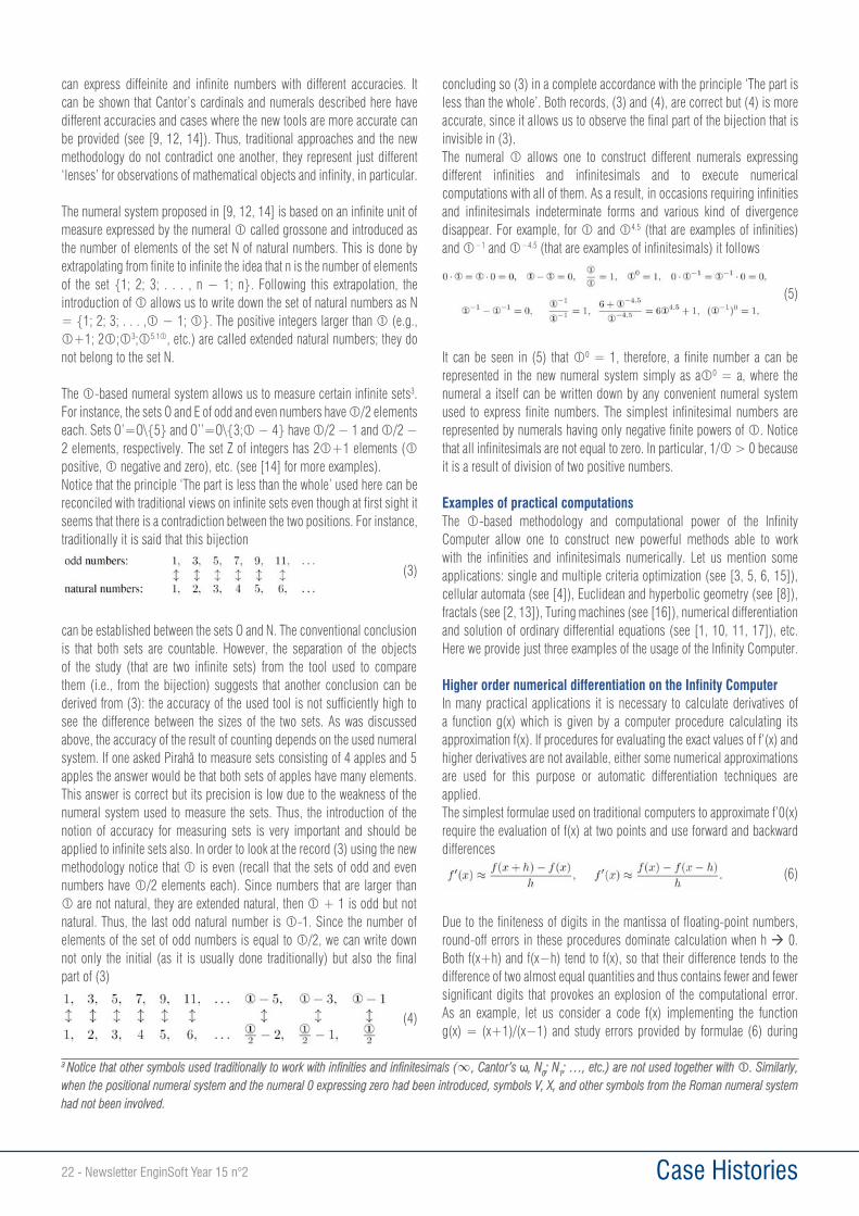
Newsletter EnginSoft Year 15 n°2 - 23 Case Histories
approximation of the value f’(y) at the point y = 3 in dependence of the step h. It can be seen from Fig. 1 that when h becomes sufficiently small the error of approximation increases drastically.Suppose now that we are in the -based framework and elementary functions (sin(x); cos(x); ax etc.) are represented on the Infinity Computer by one of the usual ways used in traditional computers. Then, we have a code f(x) implementing the already mentioned function g(x)=(x+1)/(x-1)on the Infinity Computer and we do not know the analytical representation of g(x) and f(x) is given as a black-box (i.e., we supply an x to the Infinity Computer and get f(x) without knowing how this result has been computed). Our goal is to evaluate the values f(y); f’(y); f’’(y); and f(3)(y) at the point y = 3.Instead of using formulae (6) that can lead to errors, it is proposed simply to calculate f(x) at the point x = 3 + . The result provided by the Infinity Computer is the following
i.e., f(3 + ) is a finite number with several infinitesimal parts (their number can be fixed a priori in dependence on the number of derivatives one wishes to calculate).
By taking coefficients of different powers of we get
being exact values of f(x) and of the respective derivatives at the point y = 3 (the word ‘exact’ means here ‘with the accuracy of the implementation of f(x)’, see [10] for details). Thus, only one evaluation of f(x) on the Infinity Computer gives us exact derivatives whereas on a traditional computer it is necessary to evaluate f(x) at least 4 times to get approximations of these values.
Infinite penalty coefficients in constrained non-linear optimizationIn [5], a number of interesting applications of in optimization has been proposed.One of them consists in using infinite -based penalty coefficients in order to transform a constrained optimization problem into an unconstrained one. The following example taken form [5] illustrates advantages provided by in this situation.
Let us consider the following quadratic 2-dimensional optimization problem with a single linear constraint:
The corresponding unconstrained optimization problem using a finite penalty coefficient P can be constructed as follows
Then, different values of P should be taken into consideration. For instance, let us take P = 20 and write down the first order optimality conditions
Figure 1 - When h in (6) becomes sufficiently small the error of approximation increases drastically
Grossone® Infinity Computer
we use the symbol
astronauts from NASA walk on the moon
+ 1 = + 2 =
using fly to stars and beyond
the Pirahã tribe from Amazonia uses 1, 2, many to count: 1 + 2 = many many + 1 = many many + 2 = many
2 = ma
.Pirahã cannot count beyond 2 whereas we distinguish many different finite numbers.
+ 1 > > - 1 9.3 - 5 = 4.3 7 / 2 = 3,5 6 2.3 · 5 -1.7 = 30 0.6
+
gives the possibility to distinguish many different infinities and infinitesimals.
Figure 2 - The new mathematical language using grossone and the Infinity Computer open new horizons in computations
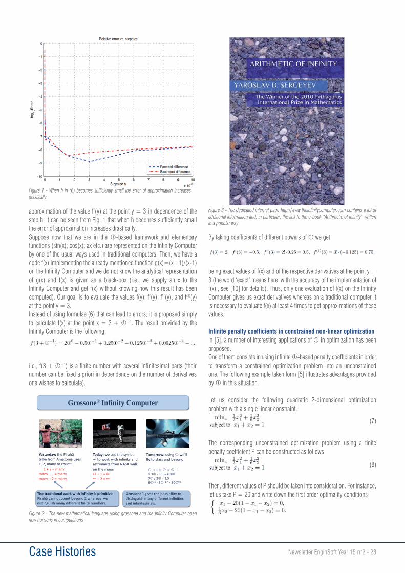
Figure 3 - The dedicated internet page http://www.theinfinitycomputer.com contains a lot of additional information and, in particular, the link to the e-book “Arithmetic of Infinity” written in a popular way
(7)
(8)
24 - Newsletter EnginSoft Year 15 n°2 Case Histories
The solution to (3.2) is the stationary point of the unconstrained problem (8) with P = 20, namely, it is
and it is not clear how to obtain from (9) the solution to the original constrained problem (7). Thus, another penalty coefficient P should be taken, the problem (8) should be solved again in order to get a new approximation to the solution of (7). This procedure should be repeated several times until a satisfactory approximation will be obtained.
In the Infinity Computer framework, the authors of [5] propose to take P = . The corresponding first order optimality conditions in this case are
and solution of this system is
The authors of [5] have proved that the finite parts of x1 and x2 give the exact solution x* = (1/4; 3/4) to the original constrained problem (7).
Numerical methods using infinitesimals for solving ODEsNumerical solutions to Ordinary Differential Equations (ODEs) are required very often in practice and there exists a huge number of numerical methods proposed to solve ODEs on conventional computers. Let us consider the following initial value problem
and suppose that f(x; y) is a ‘black-box’ function, i.e., f(x; y) is given by a computer procedure and the analytical representation of f(x; y) is unknown to the person who solves (10). As was shown in Section 3.1, the use of the Infinity Computer allows us to compute exact derivatives using the infinitesimal perturbation equal to . Let us show how this fact can be used for solving the problem (10).
The simplest algorithm to solve (10) is probably the explicit Euler Method. At each step it constructs a linear approximation of y(x) starting from the initial point (x0; y(x0)). The (n+1)th step of the Euler algorithm describes how to move from the point xn to xn+1 = xn
as follows
Let us denote by y(k)(xi) an estimate of the k-th derivative of the solution y(x) at the point xi. It has been shown in [11] that in order to calculate the k-th derivative of the unknown solution y(x) at the point xi, k infinitesimals steps from the point xi using the Euler formula with h = should be executed as follows
Since approximations of the derivatives can be obtained by the forward jh and it follows that
where (jk) is a binomial coefficient and
Then, the main observation consists of the fact that, since the error in (13) has the order equal to k -1)/ -k gives us the exact derivative y(k)(xi) (see [11]).Thus, since we are able to compute values of k derivatives of the function y(x) at a generic point x0, we can estimate y(x) in a neighborhood of the point x0 by its Taylor expansion
This means that in cases where the radius of convergence of the Taylor expansion y(x) from (14) covers the whole interval [a; b] from (10), there is no need to execute several steps with a finite value of h. In fact, thanks to the exact derivatives calculated numerically on the Infinity Computer the function y(x) can be approximated in the neighborhood of the initial point x0 by its Taylor expansion y(x) with an order k depending on the desired accuracy and then y(x) can be evaluated at any point x [a; b].This method is called Taylor for the Infinity Computer (TIC) hereinafter. It does not assume the execution of several iterations with a finite step h. The following example shows how the TIC works.Let us consider the problem
Its exact solution is
Let us construct the Taylor expansion of y(x) at the initial point x0 = 0 by applying formula (11) with h = to calculate y1 and y2:
Thus, we can calculate 2-1 as follows
Test problem y_RK4 _RK4 y_TIC _TIC N_TIC
1 0.837462 -8.62538e-009 0.837462 -5.91687e-009 6
2 1.242806 8.11157e-009 1.242806 4.19151e-009 6
3 1.221403 4.12685e-009 1.221403 2.13248e-009 6
4 1.221403 3.89834e-008 1.221403 2.13248e-009 6
5 1.491817 1.27726e-007 1.491817 1.13693e-008 7
6 0.135416 -5.96529e-004 0.135379 -3.24420e-004 10
7 36.154673 -8.16405e-005 36.149608 5.84540e-005 9
8 35.968459 -8.18293e-005 35.963409 5.85817e-005 9
9 1.239230 -5.78803e-009 1.239230 -4.08211e-009 10
10 0.781397 -1.76949e-009 0.781397 7.94128e-011 7
Table 1 - Results of a comparison on 10 test problems taken from the literature of the TIC method with the Runge-Kutta method of the 4th order that executes 20 evaluations of f(x; y) to reach the accuracy RK4
(9)
(10)
(11)
(12)
(13)
(14)
(15)
(16)
(17)
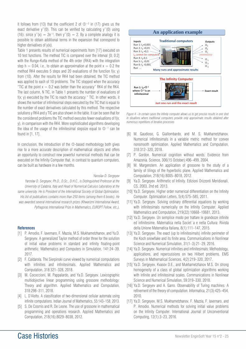
Newsletter EnginSoft Year 15 n°2 - 25 Case Histories
It follows from (13) that the coefficient 2 of in (17) gives us the exact derivative y’’(0). This can be verified by calculating y’’(0) using (16): since y’’(x) = 2e , then y’’(0) = 2. By a complete analogy it is possible to obtain additional terms in the expansion that correspond to higher derivatives of y(x).Table 1 presents results of numerical experiments from [17] executed on 10 test functions. The method TIC is compared over the interval [0; 0:2] with the Runge-Kutta method of the 4th order (RK4) with the integration step h = 0.04, i.e., to obtain an approximation at the point x = 0.2 the method RK4 executes 5 steps and 20 evaluations of the function f(x; y) from (10). After the results for RK4 had been obtained, the TIC method was applied to each of 10 problems. The TIC stopped when the accuracy “TIC at the point x = 0.2 was better than the accuracy” RK4 of the RK4. The last column, N TIC, in Table 1 presents the number of evaluations of f(x; y) executed by the TIC to reach the accuracy “ TIC. In other words, it shows the number of infinitesimal steps executed by the TIC that is equal to the number of exact derivatives calculated by this method. The respective solutions y RK4 and y TIC are also shown in the table. It can be seen that for the considered problems the TIC method executes fewer evaluations of f(x; y), in comparison with the RK4. More sophisticated algorithms developing the idea of the usage of the infinitesimal stepsize equal to can be found in [1, 17].
In conclusion, the introduction of the -based methodology both gives rise to a more accurate description of mathematical objects and offers an opportunity to construct new powerful numerical methods that can be executed on the Infinity Computer that, in contrast to quantum computers, can be built as hardware in a few months.
Yaroslav D. Sergeyev Yaroslav D. Sergeyev, Ph.D., D.Sc., D.H.C., is Distinguished Professor at the University of Calabria, Italy and Head of Numerical Calculus Laboratory at the
same university. He is President of the International Society of Global Optimization. His list of publications contains more than 250 items (among them 6 books). He
was awarded several international research prizes (Khwarizmi International Award, Pythagoras International Prize in Mathematics, EUROPT Fellow, etc.),
References[1] P. Amodio, F. Iavernaro, F. Mazzia, M.S. Mukhametzhanov, and Ya.D.
Sergeyev. A generalized Taylor method of order three for the solution of initial value problems in standard and infinity floating-point arithmetic. Mathematics and Computers in Simulation, 141:24–39, 2017.
[2] F. Caldarola. The Sierpinski curve viewed by numerical computations with infinities and infinitesimals. Applied Mathematics and Computation, 318:321–328, 2018.
[3] M. Cococcioni, M. Pappalardo, and Ya.D. Sergeyev. Lexicographic multiobjective linear programming using grossone methodology: Theory and algorithm. Applied Mathematics and Computation, 318:298–311, 2018.
[4] L. D’Alotto. A classification of two-dimensional cellular automata using infinite computations. Indian Journal of Mathematics, 55:143–158, 2013.
[5] S. De Cosmis and R. De Leone. The use of grossone in mathematical programming and operations research. Applied Mathematics and Computation, 218(16):8029–8038, 2012.
[6] M. Gaudioso, G. Giallombardo, and M. S. Mukhametzhanov. Numerical infinitesimals in a variable metric method for convex nonsmooth optimization. Applied Mathematics and Computation, 318:312–320, 2018.
[7] P. Gordon. Numerical cognition without words: Evidence from Amazonia. Science, 306(15 October):496–499, 2004.
[8] M. Margenstern. An application of grossone to the study of a family of tilings of the hyperbolic plane. Applied Mathematics and Computation, 218(16):8005–8018, 2012.
[9] Ya.D. Sergeyev. Arithmetic of Infinity. Edizioni Orizzonti Meridionali, CS, 2003, 2nd ed. 2013.
[10] Ya.D. Sergeyev. Higher order numerical differentiation on the Infinity Computer. Optimization Letters, 5(4):575–585, 2011.
[11] Ya.D. Sergeyev. Solving ordinary differential equations by working with infinitesimals numerically on the Infinity Computer. Applied Mathematics and Computation, 219(22):10668–10681, 2013.
[12] Ya.D. Sergeyev. Un semplice modo per trattare le grandezze infinite ed infinitesime. Matematica nella Societ`a e nella Cultura: Rivista della Unione Matematica Italiana, 8(1):111–147, 2015.
[13] Ya.D. Sergeyev. The exact (up to infinitesimals) infinite perimeter of the Koch snowflake and its finite area. Communications in Nonlinear Science and Numerical Simulation, 31(1–3):21–29, 2016.
[14] Ya.D. Sergeyev. Numerical infinities and infinitesimals: Methodology, applications, and repercussions on two Hilbert problems. EMS Surveys in Mathematical Sciences, 4(2):219–320, 2017.
[15] Ya.D. Sergeyev, Kvasov D.E., and Mukhametzhanov M.S. On strong homogeneity of a class of global optimization algorithms working with infinite and infinitesimal scales. Communications in Nonlinear Science and Numerical Simulation, 59:319–330, 2018.
[16] Ya.D. Sergeyev and A. Garro. Observability of Turing machines: A refinement of the theory of computation. Informatica, 21(3):425–454, 2010.
[17] Ya.D. Sergeyev, M.S. Mukhametzhanov, F. Mazzia, F. Iavernaro, and P. Amodio. Numerical methods for solving initial value problems on the Infinity Computer. International Journal of Unconventional Computing, 12(1):3–23, 2016.
An application example
Figure 4 - In certain cases the Infinity computer allows us to get precise results in one shot in situations where traditional computers provide only approximate results obtained after numerous repetitions of iterative processes

26 - Newsletter EnginSoft Year 15 n°2 Software Update
EnginSoft has recently developed a new app for ANSYS ACT to enhance the application of heat transfer between distinct surfaces via Newton’s convection law. The app is called “Convection Links” and it can be downloaded for free at the ANSYS App Store: https://appstore.ansys.com/shop/ACTApps_act%20apps.
The tool can be used in ANSYS Workbench 19 for thermal analyses.
Main capabilities:• Useful for implementing heat exchange via Newton’s convection
law, even between distant nodal surfaces, without modeling the fluid in between;
• Useful for substituting standard workbench thermal contact non-linear technology with a linear approach without losing the ability to apply a suitable contact thermal conductance;
• It supports static and transient thermal analyses;• It supports both linear or quadratic solid elements;• Units are consistent with finite element method (FEM) analysis.
Working principles:How the App works can better be understood by referring to the following picture: The ANSYS Workbench user can select two distinct groups of surfaces and set the value for the convection film coefficient. The app then automatically generates a suitable cloud of elements Link 34 from the ANSYS standard element library. Each generated link connects a couple of the closest nodes, each one belonging to each of the 2 distinct group of faces. Each generated link connects a pair of the closest nodes, one from each of the two distinct groups of surfaces. The section value for each link is attributed and balanced singularly in order to take non-uniform mesh density into account.
Conclusion:The Convection Links App generates convective thermal links between pairs of selected surfaces, both in 3D-static and thermal-transient WB models. It is based on a bulk of nested ANSYS parametric design language (APDL) macros that have been deeply tested in many different applications. A comparison between the results obtained from the APDL macros and from the Convection Links App are always the same, as depicted below:
Giovanni Falcitelli, EnginSoftFor more information:[email protected]
ConvectionLinks: EnginSoft develops a new APP for ANSYS Workbench
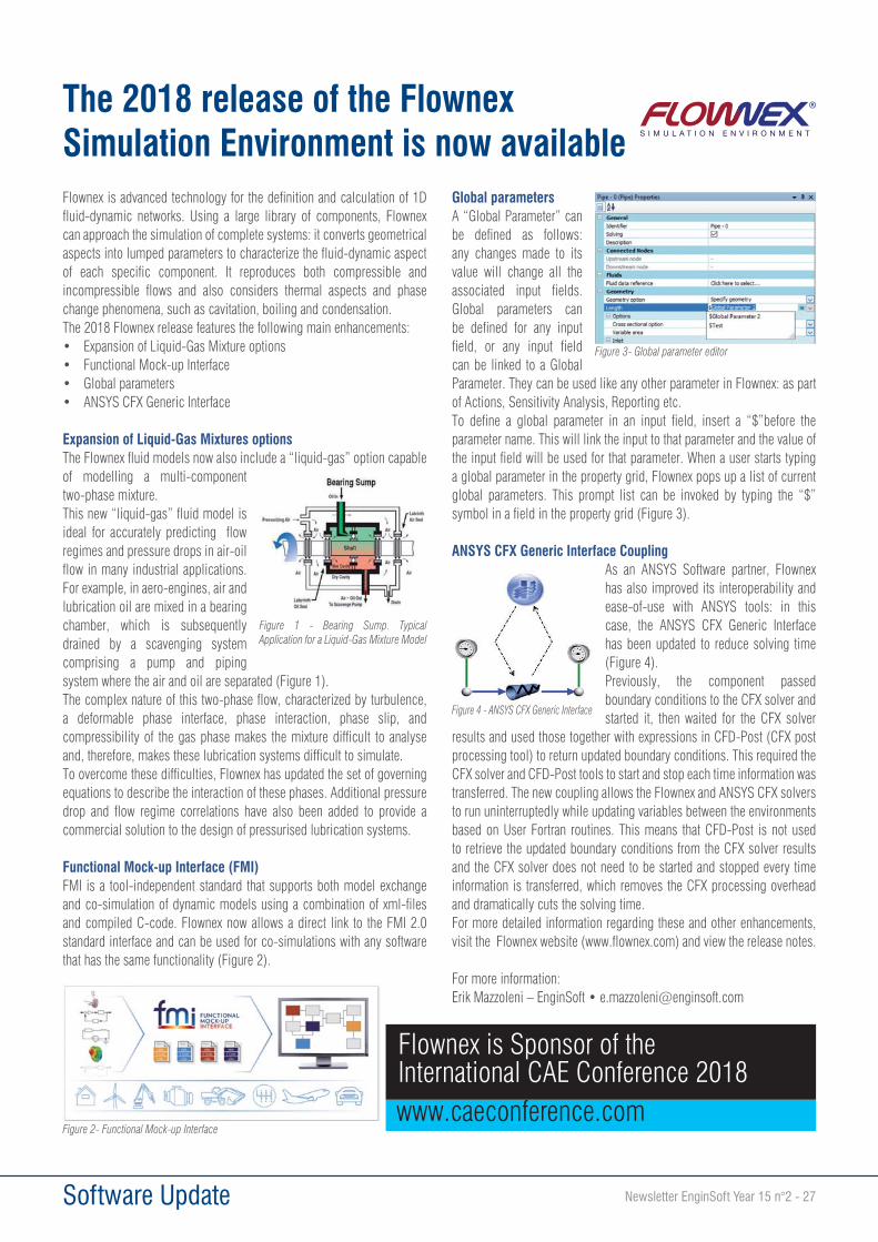
Newsletter EnginSoft Year 15 n°2 - 27
Flownex is advanced technology for the definition and calculation of 1D fluid-dynamic networks. Using a large library of components, Flownex can approach the simulation of complete systems: it converts geometrical aspects into lumped parameters to characterize the fluid-dynamic aspect of each specific component. It reproduces both compressible and incompressible flows and also considers thermal aspects and phase change phenomena, such as cavitation, boiling and condensation.The 2018 Flownex release features the following main enhancements:• Expansion of Liquid-Gas Mixture options• Functional Mock-up Interface• Global parameters• ANSYS CFX Generic Interface
Expansion of Liquid-Gas Mixtures optionsThe Flownex fluid models now also include a “liquid-gas” option capable of modelling a multi-component two-phase mixture.This new “liquid-gas” fluid model is ideal for accurately predicting flow regimes and pressure drops in air-oil flow in many industrial applications. For example, in aero-engines, air and lubrication oil are mixed in a bearing chamber, which is subsequently drained by a scavenging system comprising a pump and piping system where the air and oil are separated (Figure 1).The complex nature of this two-phase flow, characterized by turbulence, a deformable phase interface, phase interaction, phase slip, and compressibility of the gas phase makes the mixture difficult to analyse and, therefore, makes these lubrication systems difficult to simulate.To overcome these difficulties, Flownex has updated the set of governing equations to describe the interaction of these phases. Additional pressure drop and flow regime correlations have also been added to provide a commercial solution to the design of pressurised lubrication systems.
Functional Mock-up Interface (FMI) FMI is a tool-independent standard that supports both model exchange and co-simulation of dynamic models using a combination of xml-files and compiled C-code. Flownex now allows a direct link to the FMI 2.0 standard interface and can be used for co-simulations with any software that has the same functionality (Figure 2).
Global parameters A “Global Parameter” can be defined as follows: any changes made to its value will change all the associated input fields. Global parameters can be defined for any input field, or any input field can be linked to a Global Parameter. They can be used like any other parameter in Flownex: as part of Actions, Sensitivity Analysis, Reporting etc. To define a global parameter in an input field, insert a “$”before the parameter name. This will link the input to that parameter and the value of the input field will be used for that parameter. When a user starts typing a global parameter in the property grid, Flownex pops up a list of current global parameters. This prompt list can be invoked by typing the “$” symbol in a field in the property grid (Figure 3).
ANSYS CFX Generic Interface CouplingAs an ANSYS Software partner, Flownex has also improved its interoperability and ease-of-use with ANSYS tools: in this case, the ANSYS CFX Generic Interface has been updated to reduce solving time (Figure 4). Previously, the component passed boundary conditions to the CFX solver and started it, then waited for the CFX solver
results and used those together with expressions in CFD-Post (CFX post processing tool) to return updated boundary conditions. This required the CFX solver and CFD-Post tools to start and stop each time information was transferred. The new coupling allows the Flownex and ANSYS CFX solvers to run uninterruptedly while updating variables between the environments based on User Fortran routines. This means that CFD-Post is not used to retrieve the updated boundary conditions from the CFX solver results and the CFX solver does not need to be started and stopped every time information is transferred, which removes the CFX processing overhead and dramatically cuts the solving time.For more detailed information regarding these and other enhancements, visit the Flownex website (www.flownex.com) and view the release notes.
For more information:Erik Mazzoleni – EnginSoft • [email protected]
Software Update
The 2018 release of the FlownexSimulation Environment is now available
Flownex is Sponsor of the International CAE Conference 2018www.caeconference.com
Figure 1 - Bearing Sump. Typical Application for a Liquid-Gas Mixture Model
Figure 2- Functional Mock-up Interface
Figure 3- Global parameter editor
Figure 4 - ANSYS CFX Generic Interface

28 - Newsletter EnginSoft Year 15 n°2 Software Update
A new version of Rocky DEM particle simulation software has been released that expands its particle modeling capabilities and increases its support for coupled ANSYS® simulations. Significantly, this new version provides users with unique features to model both rigid and flexible particles, along with their interactions on structures and complex fluid flows. In addition, the release expands Rocky DEM multi-body motion capabilities which can be employed in numerous applications, some of which no longer require users to couple the software with an external third-party motion-body dynamics tool, making integrated setup easier. Find out what is unique in this latest version and experience everything that Rocky DEM has to offer with revolutionary new features and improved benefits
New particle and breakage modelsRocky DEM 4.1 software features new models that help users to reproduce new particle behavior under realistic conditions.
Fiber particles — This model enables users to set up and simulate the dynamics of a large number of fibers to depict behaviors such as flexibility, deformation, and inter-fiber interaction, as well as the effect of fluids on fibers through coupled simulation with ANSYS Fluent®. The fiber-particle model is especially valuable for customers in the agriculture, food, automotive, off-road, and appliance industries, where a proper understanding of fiber
behavior, such as with grass seed, hay and hair, is crucial to the optimization of equipment performance.
Shell particles — Rocky DEM 4.1 gives users the ability to simulate both rigid and flexible shell particles. Shell elements can be a huge time saver, since they enable the modeling of thin features with relatively fewer elements than solid-element modeling requires. Particulate materials like leaves and chips can be simulated much faster with this new feature. New models allow for mixed particle models — combining fibers, shells and solids — which extends the range of existing modeling possibilities.
Tavares breakage model — Based on the well-known work of Luis Marcelo Tavares (Federal University of Rio de Janeiro, Brazil), this model extends Rocky DEM’s previous breakage model by considering additional particle properties.
“The Tavares model in Rocky DEM allows more-realistic simulations of systems in which particle breakage occurs, by consistently describing size-dependent breakage probability, fragment distribution, and weakening by damage accumulation. In particular, the model is very useful for describing ore degradation during handling, as well as size reduction in different types of crushers, providing greater confidence in predicting both the proportion of broken particles and the product size,” said Professor Tavares.
ESSS releases new version of Rocky DEM software
V4.1 further enables high-fidelity particle modeling with unprecedented performance
Tablet coating study showing 1 billion elements
Flexible fibers

Newsletter EnginSoft Year 15 n°2 - 29 Software Update
New multi-body motion capabilitiesRocky DEM 4.1 takes another step forward by giving more freedom in configuring complex geometry movements, enabling users to set up as many free-body motions as needed within a motion simulation. For example, users from heavy equipment and automotive organizations won’t need to use an external, dedicated, multi-body dynamics tool to perform such analysis, which helps them to avoid additional license fees and to integrate the setupmore easily.
Extended ANSYS coupling functionalityTransient loads — Rocky DEM 4.1 supports transient loads on coupled simulations with ANSYS Mechanical™. Users can transfer loads from particles to structures in multiple time intervals to analyze the complete stress operation envelope of a dynamic process. The operation is seamlessly performed through the ANSYS Workbench™ environment, maintaining previous pervasive characteristics due to Rocky DEM’s tight integration with the Workbench framework.
Increased ANSYS Fluent support — Multiple domains and distributed simulations are now supported for both one-way and two-way coupled ANSYS Fluent problems. Users can simulate multiple fluid domains — both moving and stationary — with automatic handling of the general domain interfaces. In addition, the distributed simulation capability enables multiple simulation nodes within ANSYS Fluent to be defined directly inside the Rocky DEM interface by importing a node configuration file.
Performance improvementsFor Rocky DEM, performance is paramount. V4.1 takes a leap forward in all models, increasing scalability within multiple GPU systems for spheres and general polyhedral models. This performance improvement can achieve up to a 10-times performance gain while using 10 times less memory, even on problems involving complex concave particles, for example.
“Thanks to Rocky DEM’s solver performance improvements and multi-GPU capability, we can realistically simulate a wide range of screen sizes in our roll screener systems, all within the design phase time frame,” says Young Choi, simulation team manager at Daesung Jtech, South Korea.
The latest software also offers support for headless cluster nodes. This capability configures Rocky DEM software as cloud-ready for Google Cloud and Amazon Web Services systems.
Want to see Rocky DEM 4.1 in action? Register for this free webinar and learn more about the features and enhancements available in this release.
For more information:Massimo Tomasi - [email protected]
Transient Mechanical Coupling - Bucket excavator
Tailored for engineering design
Rocky is Sponsor of the International CAE Conference 2018www.caeconference.com
30 - Newsletter EnginSoft Year 15 n°2 Software Update
Vanderplaats Research & Development has announced the release of GENESIS 17.0 and its graphical interface, Design Studio for GENESIS 17.0.The latest version has several enhancements that improve its usability:• Acoustic analysis is now possible using the added coupled-fluid-
structure interaction module;• Changes to the optimization module enable it to handle global von
Mises stress and new random stress responses;• Updated methods for topology optimization increase polarization
and functionality;• A distinct optimizer, CMBDOT, has been added for solving
optimization problems with discrete design variables.
GENESIS structural optimization for ANSYS New features in GSAM version 17.0GENESIS Structural Optimization for ANSYS Mechanical (GSAM) is an integrated extension that adds large scale structural optimization to the ANSYS Workbench environment. GSAM allows designers to generate innovative designs that reduce costs and improve performance
while reducing engineering time. It offers very advanced topology optimization, as well as topography, freeform, sizing and topometry design and is completely integrated with the latest release of ANSYS software, version 19.0.Other worthwhile new features in GSAM ver 17.0 include:• A global von Mises stress response, called the VMINDEX response,
which allows the user to economically and efficiently impose von Mises stress constraints in topology and other types of optimizations;
• The availability of Root Mean Square/Power Spectral Density (RMS/PSD) stress responses for random vibration for all shell and solid elements;
• Progressive topology optimization, which is a method to progressively change the topology design variables in order to access more polarized topology answers;
• Another alternative for topology optimization, the Hybrid method, which allows the user to get sharper and more polarized answers;
• Tolerance for badly shaped solid elements: the model allows for second-order elements that are flat or near flat and, on finding such elements, the software will ignore them;
• The option to only write loadcases referred by optimization;• Post-processing support for binary output 2 format;• More post-processing support for more result types; and• The ability to import results for all design cycles.In conclusion, GSAM provides additional responses for optimization, a new topology optimization strategy, and improvements in input data generation and post-processing that further increase the efficiency and completeness of the software.
Martina Guidi, EnginSoft
For more information: Martina Guidi - [email protected]
New version of GENESIS 17.0 increases efficiency and completeness
Vanderplaats is Sponsor of the International CAE Conference 2018www.caeconference.com

Newsletter EnginSoft Year 15 n°2 - 31 Software Update
The automated testing of automotive control software is never easy, but there’s a product on the market that helps car makers and their suppliers to ensure that no serious bugs or design flaws occur.While the size of the code running in a typical electronic control unit (ECU) doubles every few years, the typical budget spent on testing these controllers does not. This puts increasing pressure on automotive suppliers and OEMs to ensure that no serious bugs or design flaws leak into the final product.
Testing a controller in real life requires the system to be exposed to all relevant driving situations repeatedly during the entire development cycle. Established methods -- based either on test-driving on the road, or driving a hardware-in-the-loop (HiL) simulation using hand-written test scripts -- do not scale well in
this instance, as there are simply too many situations to consider. Checking all of them, one by one, is very time consuming or not feasible. Consequently, new ideas, methods and tools to achieve a much higher degree of testing automation are required.
One proven idea is test case generation based on the computer chess principle. The key idea is simple: chess computers are very powerful and beat almost every human player, so why not exploit this power to automate system testing? After all, testing and playing chess are similar activities. For example, chess players search for a sequence of moves to checkmate their opponents in much the same way that testers search for a sequence of events which will
drive the system being tested into a state where it fails and violates the specification.
TestWeaver implements exactly this idea to automatically find flaws and bugs in control software. It uses intelligent search algorithms to maximize the coverage of both the software states and the hardware operational states. Today, automotive software developers all over the world use TestWeaver on a regular basis to test all software versions they release during a development project.
Virtual ECUsThe TestWeaver software requires executable models of the control units involved. QTronic calls these models a “virtual ECU” and offers a tool called Silver to quickly build and run from one to many such virtual ECUs on a Windows PC. A virtual ECU hosts a significant part of the control software of a real ECU and can be built either by compiling the C source codes under Windows, or by executing the binary code of the target microcontroller unit (MCU) using Silver’s chip simulator. Virtual ECUs can also be executed in external simulators, for instance via the standardized Functional Mock-Up Interface.
Today, hundreds of automotive engineers at major OEMs and suppliers use Silver to move their test, validation and calibration related activities from road and test rigs onto widely available Windows PCs. For more information, visit www.QTronic.de.
Achieving large coverage testing using Virtual ECUs
QTronic is Sponsor of the International CAE Conference 2018www.caeconference.com
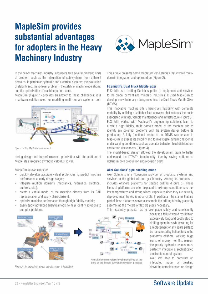
32 - Newsletter EnginSoft Year 15 n°2 Software Update
In the heavy machines industry, engineers face several different kinds of problem such as the integration of sub-systems from different domains, in particular hydraulic and electrical systems; the evaluation of stability (eg. the rollover problem); the safety of machine operations; and the optimization of machine performance.MapleSim (Figure 1) provides an answer to these challenges: it is a software solution used for modeling multi-domain systems, both
during design and in performance optimization with the addition of Maple, its associated symbolic calculus solver.
MapleSim allows users to:• quickly develop accurate virtual prototypes to predict machine
performance at early design stages;• integrate multiple domains (mechanics, hydraulics, electrical,
controls, etc.);• create a virtual model of the machine directly from its CAD
representation and easily characterize it;• optimize machine performance through high fidelity models;• easily apply advanced analytical tools to help identify solutions to
complex problems
This article presents some MapleSim case studies that involve multi-domain integration and optimization (Figure 2).
FLSmidth’s Dual Truck Mobile SizerFLSmidth is a leading Danish supplier of equipment and services to the global cement and minerals industries. It used MapleSim to develop a revolutionary mining machine: the Dual Truck Mobile Sizer (DTMS). This innovative machine offers haul-truck flexibility with complete mobility by utilizing a shiftable face conveyor that reduces the costs associated with fuel, vehicle maintenance and infrastructure (Figure 3). FLSmidth worked with Maplesoft’s engineering solutions team to create a high-fidelity, multi-domain model of the machine and to identify any potential problems with the system design before its production. A fully functional model of the DTMS was created in MapleSim to assess its stability and to investigate dynamic response under varying conditions such as operator behavior, load distribution, and terrain unevenness (Figure 4).The model-based design allowed the development team to better understand the DTMS’s functionality, thereby saving millions of dollars in both production and redesign costs.
Aker Solutions’ pipe handling craneAker Solutions is a Norwegian provider of products, systems and services to the global oil and gas industry. Among its products, it includes offshore platforms for seabed drilling (Figure 5). These kinds of platforms are often exposed to extreme conditions such as low temperatures and strong winds, especially since they are actually deployed near the Arctic polar circle. In particular, the cranes that are part of these platforms serve to assemble the drilling tube by gradually assembling the meters of flexible pipes necessary.This assembly process has to take place safely and consistently
because a failure would result in an excessively long and costly stop to drilling operations while waiting for a replacement or any spare parts to be transported by helicopters to the platforms offshore, wasting huge sums of money. For this reason, the purely hydraulic cranes must perfectly integrate a sophisticated electronic control system.Aker was able to construct an integrated model by breaking down the complex machine design
MapleSim provides substantial advantages for adopters in the Heavy Machinery Industry
Figure 1 - The MapleSim environment
Figure 2 - An example of a multi-domain system in MapleSim
TM
Newsletter EnginSoft Year 15 n°2 - 33 Software Update
into three different system models: mechanical structure, hydraulic actuation system and electrical control system.The integrated model allowed the company engineers to optimize the design across hundreds of components and thousands of parameters. Furthermore, it was possible to ensure the required level of responsiveness in the crane’s control system design, while also considering a host of other factors such as the cost, size and weight of the components, their long-term reliability and their ease of maintenance (Figure 6).
Hydraulic ForkliftIn this last case, MapleSim’s Modelon Hydraulics library was used to improve the control system of a hydraulic forklift and associate it to the movement of a mobile forklift system. A 2D model represented the forklift moving horizontally, forwards and backwards, first with the forks raised and then with the forks lowered, in order to reproduce the real movements of the forklift while unloading or loading a pallet. The height reached by the forklift was requested as an output. In addition, it represented a proportional-integral-derivative (PID) controller that handles the hydraulic cylinder connected to the multibody library components. Unlike the previous models, the engineers used some pneumatic library
components and the Modelon Hydraulics library in this case (Figure 7). MapleSim simulation environment provides tools that allow a faithful reproduction of the necessary experimental tests like handling, stability and reaching desired lift height keep costs monitored such as those coming from oil consumption. In all these examples, Maple and MapleSim allowed the engineers to quickly develop accurate virtual prototypes in order to predict machine performance at the early design stages while taking advantage of its many libraries such as:• the CAD Toolbox, Multibody, Hydraulics, and Driveline libraries
and code generation to integrate multiple domains and to create a virtual model of the machine directly from its CAD representation and to easily characterize it;
• the parameter sweep analysis, optimization toolbox, and sensitivity analysis to optimize machine performance through high fidelity models;
• the multibody analysis (and inverse kinematics) that easily apply advanced analytical tools to help find solutions to complex problems; and
• costs reduction due to the right-sizing, improved reliability and the operational speed of MapleSim’s components.
Elio De Marinis, Giovanni Borzi, EnginSoft
For more information: Giovanni Borzi - [email protected]
Figure 3 - 3D representation of a DTMS
Figure 4 - Analysis of the DTMS’s stability
Figure 5 - 3D of an Aker Solutions’ offshore platform
Figure 6 - Aker Solutions’ hydraulic crane model
Figure 7 - Implementation of a hydraulic forklift model using CAD Toolbox
Maplesoft is Sponsor of the International CAE Conference 2018www.caeconference.com

34 - Newsletter EnginSoft Year 15 n°2 Software Update
Pass/Start-Prof – A quick piping stress analysis and optimal sizing toolThe Piping and Equipment Analysis and Sizing Suite (PASS) software and its different components have already been reviewed in a series of articles in previous issues of the EnginSoft Newsletter. In this article, we examine PASS/Start-Prof, a piping stress analysis and sizing tool and the best-known component of the PASS software (Fig 1).
Piping simulation and design is, in general, quite a complex task. This should not come as a surprise, since piping systems often consist of thousands or more components that are exposed to possibly extreme environments (temperatures, pressures, wind, rain, snow, ice, seismic loads, hazardous fluids, etc.). Researchers and engineers work constantly to ensure the effective and safe operation of piping systems. As has been mentioned in previous articles, special tools are needed to consider all the possible operating conditions, the related safety code requirements, and
also the specific, complex, piping-related physical phenomena (such as Karman’s effect; the Bourdon effect; the creep and stress relaxation effect for high-temperature piping; friction forces and non-linear behavior in piping supports; complex, non-linear interactions between pipe and soil for buried pipelines; influence of piping insulation and cushioning pads; etc.). Most of this type of software is intended to be used only by piping stress analysis experts.
This makes the process of piping stress analysis quite costly and slow. Ideally, these kinds of tools should not require users to be simulation experts but should enable “regular” engineers to design safe and well performing piping systems through reliable
simulation. Fortunately, this is exactly what PASS/Start-Prof is intended to do!Is it really possible to provide a powerful piping stress analysis tool for non-simulation experts?
The short answer is “Yes!”, and thousands of successful PASS/Start-Prof users are proof of that. More than 1,500 companies in Italy, Germany, the UK, France, Finland, Japan, Korea, China, Russia and other countries already use the software every day for quick and effective stress analysis and design of different types of pipelines. Many more potential customers now have an opportunity to join them, thanks to EnginSoft, the European distributor for PASS.
There are no secret ingredients to the tool, just the conversion of extensive engineering knowledge into software, combined with advanced technologies. PASS/Start-Prof:• Integrates best-in-class modern methods, algorithms and
software libraries both proprietary and from partners all over the world;
• Features an easy-to-use, friendly graphical user interface (GUI);
• Provides flexible integration and data exchange with CAD software to make the computer-aided engineering (CAE) tool a part of any effective design workflow;
• Embeds and uses knowledge to make the tool smart; automates standard tasks; and frees up users to better focus on creativity in design;
• Assists the user by providing both contextual help and access to professional knowledge and experience in design;
• Trains the user with a focus on understanding international and national standards, model creation, results analysis, and best practices in design;
• Provides quick, professional support directly from the developers and experts;
Enabling safe, standards-based piping stress design by all engineers, faster and more cost effectively
Figure 1 - PASS/Start-Prof: Everything for piping stress analysis
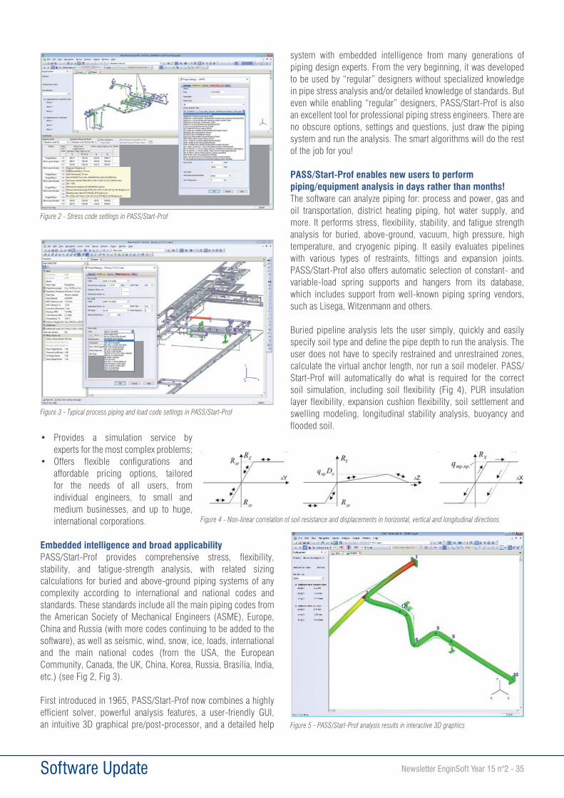
Newsletter EnginSoft Year 15 n°2 - 35 Software Update
• Provides a simulation service by experts for the most complex problems;
• Offers flexible configurations and affordable pricing options, tailored for the needs of all users, from individual engineers, to small and medium businesses, and up to huge, international corporations.
Embedded intelligence and broad applicabilityPASS/Start-Prof provides comprehensive stress, flexibility, stability, and fatigue-strength analysis, with related sizing calculations for buried and above-ground piping systems of any complexity according to international and national codes and standards. These standards include all the main piping codes from the American Society of Mechanical Engineers (ASME), Europe, China and Russia (with more codes continuing to be added to the software), as well as seismic, wind, snow, ice, loads, international and the main national codes (from the USA, the European Community, Canada, the UK, China, Korea, Russia, Brasilia, India, etc.) (see Fig 2, Fig 3).
First introduced in 1965, PASS/Start-Prof now combines a highly efficient solver, powerful analysis features, a user-friendly GUI, an intuitive 3D graphical pre/post-processor, and a detailed help
system with embedded intelligence from many generations of piping design experts. From the very beginning, it was developed to be used by “regular” designers without specialized knowledge in pipe stress analysis and/or detailed knowledge of standards. But even while enabling “regular” designers, PASS/Start-Prof is also an excellent tool for professional piping stress engineers. There are no obscure options, settings and questions, just draw the piping system and run the analysis. The smart algorithms will do the rest of the job for you!
PASS/Start-Prof enables new users to perform piping/equipment analysis in days rather than months!The software can analyze piping for: process and power, gas and oil transportation, district heating piping, hot water supply, and more. It performs stress, flexibility, stability, and fatigue strength analysis for buried, above-ground, vacuum, high pressure, high temperature, and cryogenic piping. It easily evaluates pipelines with various types of restraints, fittings and expansion joints. PASS/Start-Prof also offers automatic selection of constant- and variable-load spring supports and hangers from its database, which includes support from well-known piping spring vendors, such as Lisega, Witzenmann and others.
Buried pipeline analysis lets the user simply, quickly and easily specify soil type and define the pipe depth to run the analysis. The user does not have to specify restrained and unrestrained zones, calculate the virtual anchor length, nor run a soil modeler. PASS/Start-Prof will automatically do what is required for the correct soil simulation, including soil flexibility (Fig 4), PUR insulation layer flexibility, expansion cushion flexibility, soil settlement and swelling modeling, longitudinal stability analysis, buoyancy and flooded soil.
Figure 2 - Stress code settings in PASS/Start-Prof
Figure 3 - Typical process piping and load code settings in PASS/Start-Prof
Figure 4 - Non-linear correlation of soil resistance and displacements in horizontal, vertical and longitudinal directions
Figure 5 - PASS/Start-Prof analysis results in interactive 3D graphics
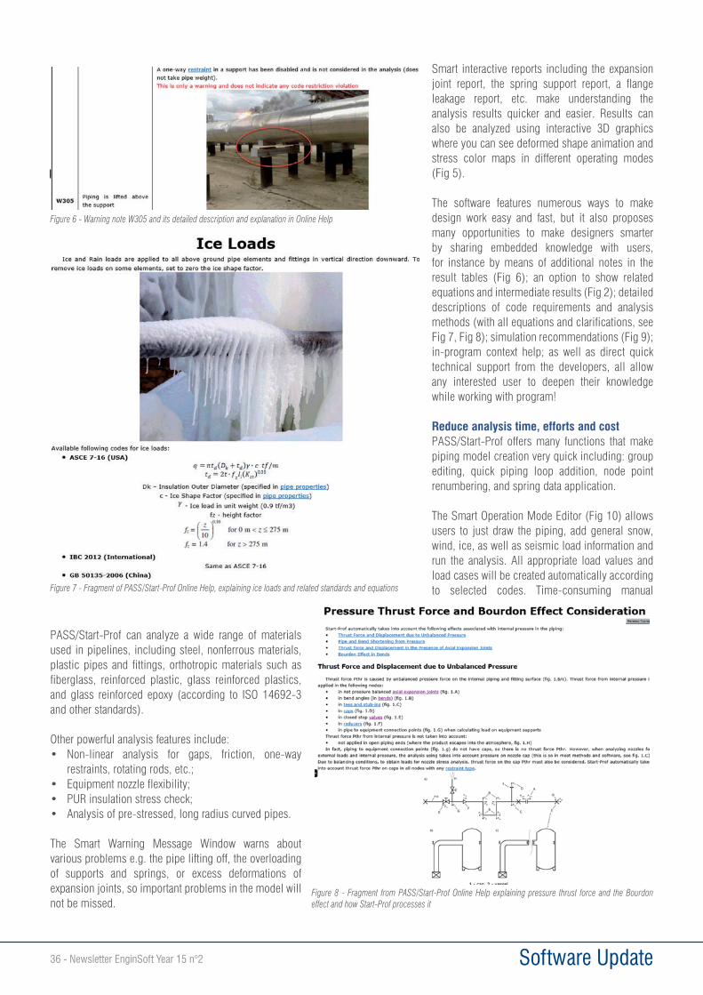
36 - Newsletter EnginSoft Year 15 n°2 Software Update
PASS/Start-Prof can analyze a wide range of materials used in pipelines, including steel, nonferrous materials, plastic pipes and fittings, orthotropic materials such as fiberglass, reinforced plastic, glass reinforced plastics, and glass reinforced epoxy (according to ISO 14692-3 and other standards).
Other powerful analysis features include: • Non-linear analysis for gaps, friction, one-way
restraints, rotating rods, etc.;• Equipment nozzle flexibility;• PUR insulation stress check;• Analysis of pre-stressed, long radius curved pipes.
The Smart Warning Message Window warns about various problems e.g. the pipe lifting off, the overloading of supports and springs, or excess deformations of expansion joints, so important problems in the model will not be missed.
Smart interactive reports including the expansion joint report, the spring support report, a flange leakage report, etc. make understanding the analysis results quicker and easier. Results can also be analyzed using interactive 3D graphics where you can see deformed shape animation and stress color maps in different operating modes (Fig 5).
The software features numerous ways to make design work easy and fast, but it also proposes many opportunities to make designers smarter by sharing embedded knowledge with users, for instance by means of additional notes in the result tables (Fig 6); an option to show related equations and intermediate results (Fig 2); detailed descriptions of code requirements and analysis methods (with all equations and clarifications, see Fig 7, Fig 8); simulation recommendations (Fig 9); in-program context help; as well as direct quick technical support from the developers, all allow any interested user to deepen their knowledge while working with program!
Reduce analysis time, efforts and costPASS/Start-Prof offers many functions that make piping model creation very quick including: group editing, quick piping loop addition, node point renumbering, and spring data application.
The Smart Operation Mode Editor (Fig 10) allows users to just draw the piping, add general snow, wind, ice, as well as seismic load information and run the analysis. All appropriate load values and load cases will be created automatically according to selected codes. Time-consuming manual
Figure 6 - Warning note W305 and its detailed description and explanation in Online Help
Figure 7 - Fragment of PASS/Start-Prof Online Help, explaining ice loads and related standards and equations
Figure 8 - Fragment from PASS/Start-Prof Online Help explaining pressure thrust force and the Bourdon effect and how Start-Prof processes it

Newsletter EnginSoft Year 15 n°2 - 37 Software Update
creation of load cases is no longer needed. PASS/Start-Prof can import piping models ready for analysis from AVEVA Plant Design Management System (PDMS) and Everything 3D (E3D), Caesar II, as well as from other Plant/Piping CAD systems via Piping Component File format (PCF). Data can also be exchanged within the PASS suite and with a large spectrum of general and special purpose CAD and CAE software tools. This makes PASS/Start-Prof an ideal component for integration into any piping design workflow.
Express analysis and sizingAlong with analyzing piping systems of any complexity, PASS/Start-Prof performs a wide spectrum of calculations “on the fly” thereby helping piping designers to make the right decisions (Fig 11).PASS/Start-Prof calculates pipe and fitting wall thicknesses, span lengths, as well as sizes of typical piping assemblies (including different types of buried and above-ground, L-, Z- and U-shaped piping loops). It also checks flange leakage, pump and equipment loads, buried and above-ground pipeline longitudinal stability, pipe wall stability under vacuum, and other loads. It can calculate the allowable load on saddle supports for large-diameter pipes and check the loads on centrifugal pump nozzles per the international API 610 (ISO 13709) standard and the Kellogg method (as per L.C. Peng).
Flexible configurationsPASS/Start-Prof can be delivered in different configurations to evaluate the piping stresses, displacements, and support loads from thermal expansion, cold spring, soil and support subsidence, and other loads according to applicable standards and codes:
PASS/Start-Prof Complete provides simulation and sizing for any piping network, considering all applicable national codes;
PASS/Start-Prof Power provides simulation and sizing for any piping networks based on applicable national codes for power generation piping as well as for central heating networks;
PASS/Start-Prof Process provides simulation and sizing for piping networks based on applicable national codes for process plants as well as for gas and oil transportation systems.Start-Prof is your PASS to the world of piping stress analysis! Try it now!
Alexey Matveev, Leonid KorelsteinPSRE Co (NTP Truboprovod)
For more information: Livio Furlan - EnginSoft [email protected]
Figure 10 - Smart Operation Mode Editor in PASS/Start-Prof
Figure 11- Express analysis and sizing in PASS/Start-Prof
Figure 9 - Fragment of PASS/Start-Prof Online Help section explaining how to model discharge pressure relief systems
NTP Truboprovod is Sponsor of the International CAE Conference 2018
www.caeconference.com
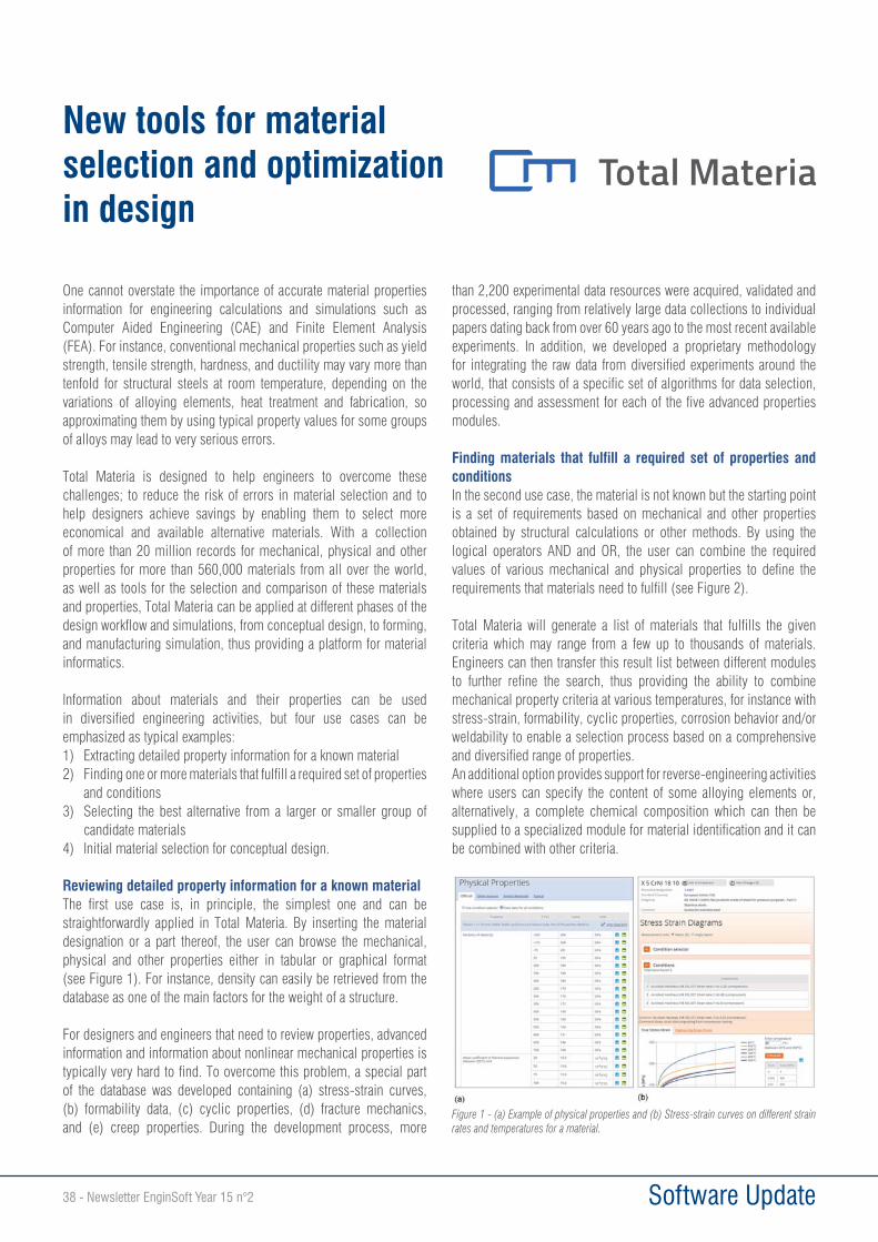
38 - Newsletter EnginSoft Year 15 n°2 Software Update
One cannot overstate the importance of accurate material properties information for engineering calculations and simulations such as Computer Aided Engineering (CAE) and Finite Element Analysis (FEA). For instance, conventional mechanical properties such as yield strength, tensile strength, hardness, and ductility may vary more than tenfold for structural steels at room temperature, depending on the variations of alloying elements, heat treatment and fabrication, so approximating them by using typical property values for some groups of alloys may lead to very serious errors.
Total Materia is designed to help engineers to overcome these challenges; to reduce the risk of errors in material selection and to help designers achieve savings by enabling them to select more economical and available alternative materials. With a collection of more than 20 million records for mechanical, physical and other properties for more than 560,000 materials from all over the world, as well as tools for the selection and comparison of these materials and properties, Total Materia can be applied at different phases of the design workflow and simulations, from conceptual design, to forming, and manufacturing simulation, thus providing a platform for material informatics.
Information about materials and their properties can be used in diversified engineering activities, but four use cases can be emphasized as typical examples:1) Extracting detailed property information for a known material 2) Finding one or more materials that fulfill a required set of properties
and conditions3) Selecting the best alternative from a larger or smaller group of
candidate materials4) Initial material selection for conceptual design.
Reviewing detailed property information for a known materialThe first use case is, in principle, the simplest one and can be straightforwardly applied in Total Materia. By inserting the material designation or a part thereof, the user can browse the mechanical, physical and other properties either in tabular or graphical format (see Figure 1). For instance, density can easily be retrieved from the database as one of the main factors for the weight of a structure.
For designers and engineers that need to review properties, advanced information and information about nonlinear mechanical properties is typically very hard to find. To overcome this problem, a special part of the database was developed containing (a) stress-strain curves, (b) formability data, (c) cyclic properties, (d) fracture mechanics, and (e) creep properties. During the development process, more
than 2,200 experimental data resources were acquired, validated and processed, ranging from relatively large data collections to individual papers dating back from over 60 years ago to the most recent available experiments. In addition, we developed a proprietary methodology for integrating the raw data from diversified experiments around the world, that consists of a specific set of algorithms for data selection, processing and assessment for each of the five advanced properties modules.
Finding materials that fulfill a required set of properties and conditionsIn the second use case, the material is not known but the starting point is a set of requirements based on mechanical and other properties obtained by structural calculations or other methods. By using the logical operators AND and OR, the user can combine the required values of various mechanical and physical properties to define the requirements that materials need to fulfill (see Figure 2).
Total Materia will generate a list of materials that fulfills the given criteria which may range from a few up to thousands of materials. Engineers can then transfer this result list between different modules to further refine the search, thus providing the ability to combine mechanical property criteria at various temperatures, for instance with stress-strain, formability, cyclic properties, corrosion behavior and/or weldability to enable a selection process based on a comprehensive and diversified range of properties. An additional option provides support for reverse-engineering activities where users can specify the content of some alloying elements or, alternatively, a complete chemical composition which can then be supplied to a specialized module for material identification and it can be combined with other criteria.
New tools for material selection and optimization in design
Figure 1 - (a) Example of physical properties and (b) Stress-strain curves on different strain rates and temperatures for a material.
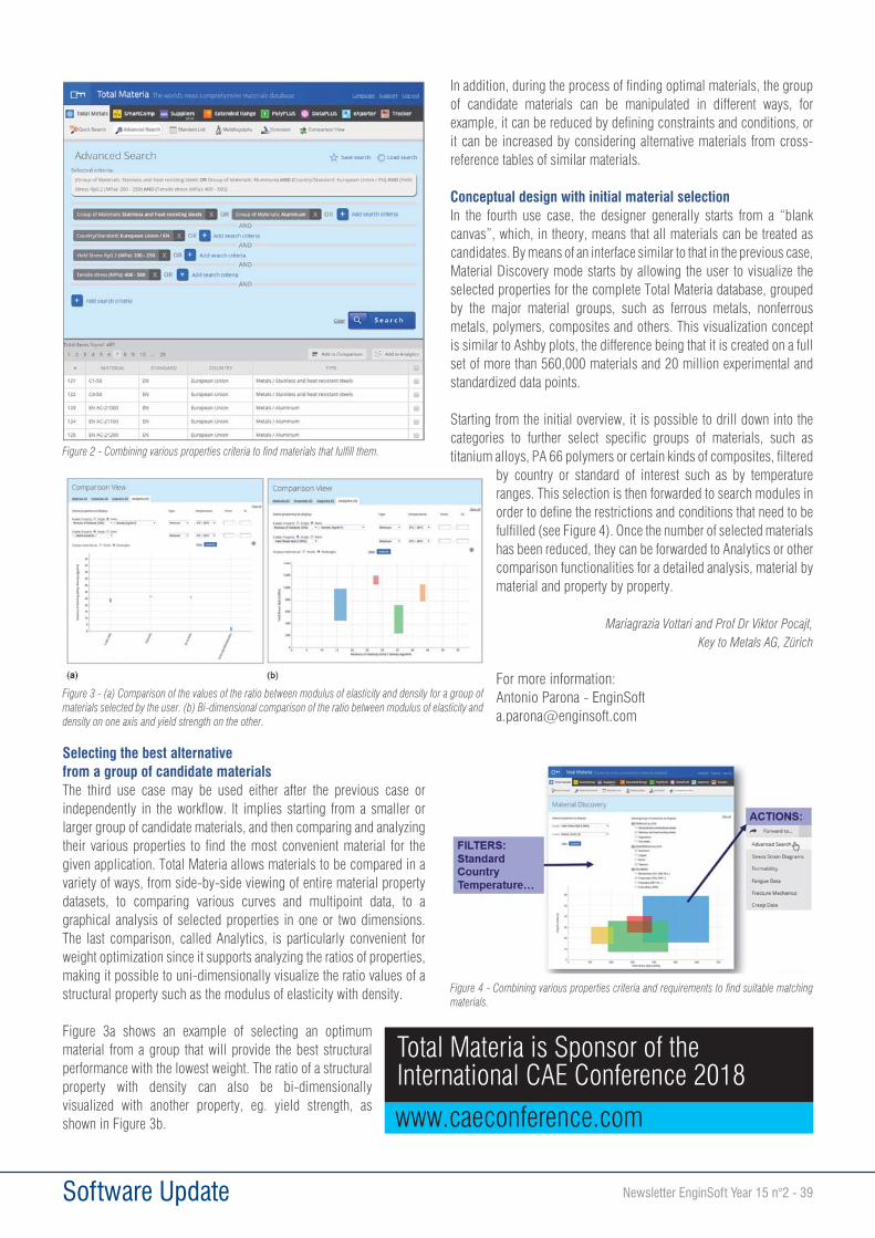
Newsletter EnginSoft Year 15 n°2 - 39 Software Update
Selecting the best alternative from a group of candidate materialsThe third use case may be used either after the previous case or independently in the workflow. It implies starting from a smaller or larger group of candidate materials, and then comparing and analyzing their various properties to find the most convenient material for the given application. Total Materia allows materials to be compared in a variety of ways, from side-by-side viewing of entire material property datasets, to comparing various curves and multipoint data, to a graphical analysis of selected properties in one or two dimensions. The last comparison, called Analytics, is particularly convenient for weight optimization since it supports analyzing the ratios of properties, making it possible to uni-dimensionally visualize the ratio values of a structural property such as the modulus of elasticity with density.
Figure 3a shows an example of selecting an optimum material from a group that will provide the best structural performance with the lowest weight. The ratio of a structural property with density can also be bi-dimensionally visualized with another property, eg. yield strength, as shown in Figure 3b.
In addition, during the process of finding optimal materials, the group of candidate materials can be manipulated in different ways, for example, it can be reduced by defining constraints and conditions, or it can be increased by considering alternative materials from cross-reference tables of similar materials.
Conceptual design with initial material selectionIn the fourth use case, the designer generally starts from a “blank canvas”, which, in theory, means that all materials can be treated as candidates. By means of an interface similar to that in the previous case, Material Discovery mode starts by allowing the user to visualize the selected properties for the complete Total Materia database, grouped by the major material groups, such as ferrous metals, nonferrous metals, polymers, composites and others. This visualization concept is similar to Ashby plots, the difference being that it is created on a full set of more than 560,000 materials and 20 million experimental and standardized data points.
Starting from the initial overview, it is possible to drill down into the categories to further select specific groups of materials, such as titanium alloys, PA 66 polymers or certain kinds of composites, filtered
by country or standard of interest such as by temperature ranges. This selection is then forwarded to search modules in order to define the restrictions and conditions that need to be fulfilled (see Figure 4). Once the number of selected materials has been reduced, they can be forwarded to Analytics or other comparison functionalities for a detailed analysis, material by material and property by property.
Mariagrazia Vottari and Prof Dr Viktor Pocajt, Key to Metals AG, Zürich
For more information: Antonio Parona - EnginSoft [email protected]
Figure 2 - Combining various properties criteria to find materials that fulfill them.
Figure 3 - (a) Comparison of the values of the ratio between modulus of elasticity and density for a group of materials selected by the user. (b) Bi-dimensional comparison of the ratio between modulus of elasticity and density on one axis and yield strength on the other.
Figure 4 - Combining various properties criteria and requirements to find suitable matching materials.
Total Materia is Sponsor of the International CAE Conference 2018
www.caeconference.com
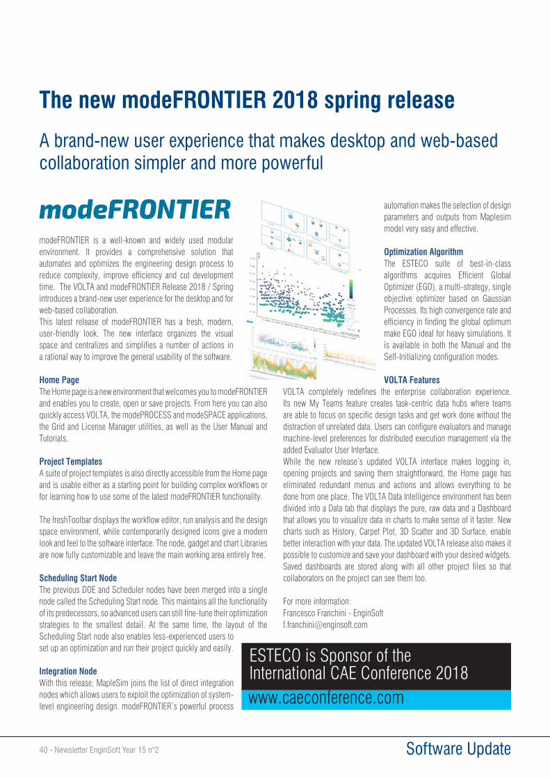
40 - Newsletter EnginSoft Year 15 n°2 Software Update
modeFRONTIER is a well-known and widely used modular environment. It provides a comprehensive solution that automates and optimizes the engineering design process to reduce complexity, improve efficiency and cut development time. The VOLTA and modeFRONTIER Release 2018 / Spring introduces a brand-new user experience for the desktop and for web-based collaboration. This latest release of modeFRONTIER has a fresh, modern, user-friendly look. The new interface organizes the visual space and centralizes and simplifies a number of actions in a rational way to improve the general usability of the software.
Home PageThe Home page is a new environment that welcomes you to modeFRONTIER and enables you to create, open or save projects. From here you can also quickly access VOLTA, the modePROCESS and modeSPACE applications, the Grid and License Manager utilities, as well as the User Manual and Tutorials.
Project TemplatesA suite of project templates is also directly accessible from the Home page and is usable either as a starting point for building complex workflows or for learning how to use some of the latest modeFRONTIER functionality.
The freshToolbar displays the workflow editor, run analysis and the design space environment, while contemporarily designed icons give a modern look and feel to the software interface. The node, gadget and chart Libraries are now fully customizable and leave the main working area entirely free.
Scheduling Start NodeThe previous DOE and Scheduler nodes have been merged into a single node called the Scheduling Start node. This maintains all the functionality of its predecessors, so advanced users can still fine-tune their optimization strategies to the smallest detail. At the same time, the layout of the Scheduling Start node also enables less-experienced users to set up an optimization and run their project quickly and easily.
Integration NodeWith this release, MapleSim joins the list of direct integration nodes which allows users to exploit the optimization of system-level engineering design. modeFRONTIER’s powerful process
automation makes the selection of design parameters and outputs from Maplesim model very easy and effective.
Optimization AlgorithmThe ESTECO suite of best-in-class algorithms acquires Efficient Global Optimizer (EGO), a multi-strategy, single objective optimizer based on Gaussian Processes. Its high convergence rate and efficiency in finding the global optimum make EGO ideal for heavy simulations. It is available in both the Manual and the Self-Initializing configuration modes.
VOLTA FeaturesVOLTA completely redefines the enterprise collaboration experience. Its new My Teams feature creates task-centric data hubs where teams are able to focus on specific design tasks and get work done without the distraction of unrelated data. Users can configure evaluators and manage machine-level preferences for distributed execution management via the added Evaluator User Interface.While the new release’s updated VOLTA interface makes logging in, opening projects and saving them straightforward, the Home page has eliminated redundant menus and actions and allows everything to be done from one place. The VOLTA Data Intelligence environment has been divided into a Data tab that displays the pure, raw data and a Dashboard that allows you to visualize data in charts to make sense of it faster. New charts such as History, Carpet Plot, 3D Scatter and 3D Surface, enable better interaction with your data. The updated VOLTA release also makes it possible to customize and save your dashboard with your desired widgets. Saved dashboards are stored along with all other project files so that collaborators on the project can see them too.
For more information:Francesco Franchini - [email protected]
The new modeFRONTIER 2018 spring release
A brand-new user experience that makes desktop and web-based collaboration simpler and more powerful
ESTECO is Sponsor of the International CAE Conference 2018www.caeconference.com
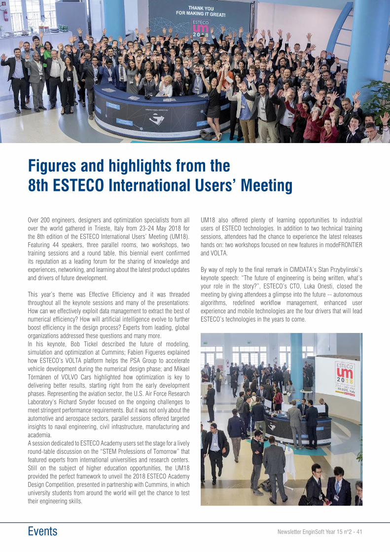
Newsletter EnginSoft Year 15 n°2 - 41 Events
Over 200 engineers, designers and optimization specialists from all over the world gathered in Trieste, Italy from 23-24 May 2018 for the 8th edition of the ESTECO International Users’ Meeting (UM18). Featuring 44 speakers, three parallel rooms, two workshops, two training sessions and a round table, this biennial event confirmed its reputation as a leading forum for the sharing of knowledge and experiences, networking, and learning about the latest product updates and drivers of future development.
This year’s theme was Effective Efficiency and it was threaded throughout all the keynote sessions and many of the presentations: How can we effectively exploit data management to extract the best of numerical efficiency? How will artificial intelligence evolve to further boost efficiency in the design process? Experts from leading, global organizations addressed these questions and many more.In his keynote, Bob Tickel described the future of modeling, simulation and optimization at Cummins; Fabien Figueres explained how ESTECO’s VOLTA platform helps the PSA Group to accelerate vehicle development during the numerical design phase; and Mikael Törmänen of VOLVO Cars highlighted how optimization is key to delivering better results, starting right from the early development phases. Representing the aviation sector, the U.S. Air Force Research Laboratory‘s Richard Snyder focused on the ongoing challenges to meet stringent performance requirements. But it was not only about the automotive and aerospace sectors, parallel sessions offered targeted insights to naval engineering, civil infrastructure, manufacturing and academia. A session dedicated to ESTECO Academy users set the stage for a lively round-table discussion on the “STEM Professions of Tomorrow” that featured experts from international universities and research centers. Still on the subject of higher education opportunities, the UM18 provided the perfect framework to unveil the 2018 ESTECO Academy Design Competition, presented in partnership with Cummins, in which university students from around the world will get the chance to test their engineering skills.
UM18 also offered plenty of learning opportunities to industrial users of ESTECO technologies. In addition to two technical training sessions, attendees had the chance to experience the latest releases hands on: two workshops focused on new features in modeFRONTIER and VOLTA.
By way of reply to the final remark in CIMDATA’s Stan Przybylinski’s keynote speech: “The future of engineering is being written, what’s your role in the story?”, ESTECO’s CTO, Luka Onesti, closed the meeting by giving attendees a glimpse into the future -- autonomous algorithms, redefined workflow management, enhanced user experience and mobile technologies are the four drivers that will lead ESTECO’s technologies in the years to come.
Figures and highlights from the 8th ESTECO International Users’ Meeting

42 - Newsletter EnginSoft Year 15 n°2 Events
PISA, 21 MAY 2018 - The International Robotics Festival of Pisa is back for the second edition, from 27th September to 3rd October in various locations of the city that boasts one of the highest concentrations in the world for employees, researchers, development and application activities of robotic systems involved.
Expanded and important public bodies’ network recognizes in the Festival a key event for the development of the territory, signing in these days the Memorandum of Understanding that sees engaging in its support Tuscany Region, Municipality of Pisa, Province of Pisa, University of Pisa, Scuola Normale Superiore, Sant’Anna School of Advanced Studies of Pisa, National Research Council of Pisa, BioRobotics Institute of Sant’Anna School of Advanced Studies, “E.Piaggio” Research Center, ENDOCAS Center of Excellence of the University of Pisa, IRCCS Stella Maris, Chamber of Commerce, Industry of Pisa, Hospital of Pisa and Arpa Foundation.
Ethical, social, economic implications of robotics, legal regulation of robotics, robotics in health care, humanitarian cooperation, recreational boating for able-bodied and disabled persons, Green Economy and recovery and conservation of cultural heritage, emotional implication of robotics, the role of nurses and technicians in the management of technologies, as well as robotics in sport and industry, robotics and the implications on the labor market are some of the themes which will be developed in this edition (see complete list on the festival website).
Regarding educational robotics, International Robotics Festival will be present in the context of the Internet Festival (from 11th to 14th October 2018 in Pisa), with educational robotics workshops designed for T-TOUR schools, for a common commitment in favor of teaching that facilitates and optimizes the involvement of students, teachers and all those who want to deepen their knowledge in this field or confront themselves for the first time with the scenarios of the future.
As for last year a wide cultural offer is planned, made up of concerts, shows, and the Pisa Robot Film Festival.
The main locations of the International Robotics Festival in Pisa will be Arsenali Repubblicani and Stazione Leopolda, Convento delle Benedettine, Scuola Normale Superiore in Pisa, Sant’Anna School of Advanced Studies in Pisa, Navicelli, Opera della Primaziale Pisana, Chamber of Commerce of Pisa, ENEL Research Center of Pisa, Industrial Union of Pisa, Domus Mazziniana of Pisa, Officine Garibaldi of Pisa, Palazzo della
Sapienza of Pisa, Migliarino San Rossore Massaciuccoli Natural Park, Teatro Puccini di Torre del Lago Puccini of Lucca, Piaggio Foundation of Pontedera, Torre Guelfa della Cittadella of Pisa, Museum of Ancient Ships of Pisa with the Shipyard of the Ancient Ships and the Center of Wet Wood Restoration.
Director of the second International Robotics Festival is Franco Mosca, President of the Arpa Foundation and Professor Emeritus of General Surgery at the University of Pisa.
Mark the date. Here are the main artistic and social events of the Festival program: Thursday, 27th September, Inauguration at the Teatro Verdi; Friday, September 28th, Researchers’ Night, with artistic events spread in various locations of Pisa; Saturday, September 29th 6:00 PM Concert “LOLA”, at Aula Magna della Sapienza, University of Pisa, and 9:00 PM “ROBOTopera” at the Puccini Festival of Torre del Lago Puccini, Lucca; Sunday, September 30th Concert with the Guitar by Mazzini, at Domus Mazziniana; Monday, October 1st 6:00 PM Concert of ancient instruments at the Domus Mazziniana and 9:00 PM
“Totentanz” by F. Liszt at Monumental Camposanto of the Duomo of Pisa; Tuesday, October 2nd “Don Cristobal” Opera at the Gipsoteca of Ancient Art of the University of Pisa; Wednesday, October 3rd closingConcert with Maestro Andrea Bocelli and Soprano Maria Luigia Borsi at the Teatro Verdi.
International Robotics Festival, Pisahttp://www.festivalinternazionaledellarobotica.it/en/
Robotics. After the great success of the firstedition, the International Robotics Festival ofPisa returns from September 27th to October 3rd
Newsletter EnginSoft Year 15 n°2 - 43 Events
The role of Engineering Simulation in Industry 4.0Engineering simulation has an important role to play as the world intently begins embracing the Industry 4.0 evolution. Not only can simulation assist strategically with the entire product design process and the related manufacturing and production processes, but it can also drill right down into the operations level, following the product throughout its entire useful life. Engineering simulation can enable companies to:• perform predictive maintenance;• explore new product uses:• develop product variations or responsive product designs;• analyse and better understand life-time performance or wear-and-
tear using real-world data; or• study potential malfunctions and weak points by simulating
product interaction with real-world environments, based on sensor feedback.
These findings and discoveries can be fed back into the design process for the entire product lifecycle, to optimise product design, performance, maintenance, redundancy and eventual mortality.
Digital twins: Allowing business to explore the possibilities while developing effective responses to the challenges of Industry 4.0One of simulation’s biggest contributions is to the growing trend of using digital twins in product engineering. A digital twin is a virtual model (often actually a meta-model) that accurately replicates a physical asset, service or process and allows it to be manipulated to explore the impacts and effects of different variables and dynamics. International research firm Gartner, named digital twins as one of its Top 10 Strategic Technology Trends in both 2017 and 2018. Digital twins allow companies to explore the implications of this new frontier of business (where the merger of physical products with digital and communications technologies is successively transforming not only the global engineering industry, but business as we’ve known it), and to develop effective responses to the various and demanding conditions and challenges it represents. It takes “what-if” planning and strategizing into this new dimension.
Revealing unseen and unexpected potentialities hidden in products, systems and processesThis year’s CAE Conference will deeply explore how Engineering Simulation is evolving to embrace and even progress the different technologies that are contributing to the development of Industry
4.0. A key advantage of Engineering Simulation is its ability to reveal the unseen and unexpected potentialities of product engineering and of the product manufacturing process. These potentials can then be developed and exploited to lower costs, improve productivity, optimise resources, to enhance existing products and services, and to identify possible new products, services and even markets.
The International CAE Conference and Exhibition 2018Building on an enviable 34-year track record of commanding attention and stimulating debate about the state of the art and the potential of Engineering Simulation, this year’s conference offers a richer, more substantial and more tightly integrated ecosystem than ever. The programme includes:• Conference sessions with a variety of tracks both for industry
sectors and about enabling technologies;• The exhibition, where Industry 4.0 technology providers – including
IoT, additive manufacturing, augmented reality, robotics, system engineering, cyber security, embedded software, and the like – will showcase their products, providing tangible evidence of the evolution of product engineering;
• Side events that will feature contributions from the world of mathematics, robotics, material science, high performance computing and more, and which will set new industry targets based on the needs expressed by various industry associations;
• The Research Agorà that offers a representative sample of the major on-going European research projects in the field;
• The Best Poster Award which testifies to the visionary understanding of the new generation of engineers and scientists spanning new fields and also supports the discussion around how education should help this evolution.
All in all, the International CAE Conference and Exhibition 2018 will offer the most intense and concentrated forum for all the stakeholders that can benefit from the Engineering Simulation world.
Evolving Engineering Simulation:THE AGE OF THE DIGITAL TWIN
2018 INTERNATIONAL CAE CONFERENCEAND EXHIBITION

EVOLVING ENGINEERING SIMULATION:THE AGE OF THE DIGITAL TWIN
20188 - 9 OCTOBER
Vicenza Convention Centre@Fiera di Vicenza
Vicenza, ITALY
WWW.CAECONFERENCE.COM
34th INTERNATIONAL CAE CONFERENCE AND EXHIBITION