Embed Size (px)
Citation preview
CCRRNN && CCGGAA AAPPPPRROOVVEEDD AASSSSEEMM--BBLLIIEESS,,
Braided Flexible Pump Connectors are constructed of stainlesssteel annular corrugated metal hose surrounded with a heavy duty woven wire braidof high tensile stainless steel. This combination provides a highly flexible unit (with alonger service life than lighter duty type connectors) which has high pressure andtemperature capability that can absorb pump vibration and noise, accept thermalexpansion and reduce piping stress due to minor misalignment and pressure variations.
The reduction of stress on your pumps and compressor housings can greatly reduceyour long term operation and maintenance costs.
Standard end fittings for connectors include carbon steel male nipples for sizes 1/2"through 2". Sizes 2-1/2" and larger have forged steel weld neck or slip on flangeswith ASA 150# bolt hole patterns. Other fittings are available on request.
Expansion JointsExpansion joints absorb movement in piping caused by thermal changes.Superior designs, manufacturing and extensive testing techniques assure you,our customer, of purchasing the best expansion joint being offered today.
Teflon HoseTeflon hose is extruded, then covered by a bronze or stainless steel wire reinforcing braid. Smooth bore and convoluted Teflon hose is lightweight andinert to most chemicals; it can be used for conveying liquids and gases.
Stainless Steel FittingsSSP fittings manufactures precision screw machine products and is an ISO-9001 certified designer and manufacturer of hydraulic fittings. Stainless steelconnectors, adapters and fittings available from stock.
Stripwound HoseStripwound hose is manufactured by spirally winding a preformed continuousmetal strip. It is used for conveying oils, tar, asphalt, steam and exhaust fumes;also for dry product transfer, or as a protective armor.
Hose, Ducts & ConnectorsMade of silicones, neoprenes and other elastomers for the movement of air,liquids or flowable solids, transportation, chemical processing and maintenanceneeds of industry throughout the world.
Industrial Tube & Pipe FittingsComplete range of industrial tube and pipe fittings manufactured to meet SAEand Military Standards. Methods of manufacturing include: hot forging, hotforming and screw machining from extruded bar stock from steel, brass orstainless steel.
Head Office
4291 Garand StreetMontreal, QuebecH4R 2B4, CanadaToll Free:Tel.: 877-335-7755Fax: 877-335-6504
established in 1994, registered ISO 9001:2000, is now a leading manufacturer of fluid conveying and connecting products. Our commitment to total quality, underlines our capability to provide excellent service and products to meet our clients most demanding needs.
Visit our web site at: www.connectallltd.com
NEWNEW
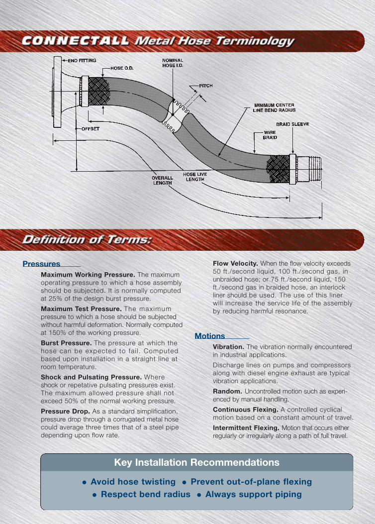
PressuresMaximum Working Pressure. The maximumoperating pressure to which a hose assemblyshould be subjected. It is normally computedat 25% of the design burst pressure.
Maximum Test Pressure. The maximumpressure to which a hose should be subjectedwithout harmful deformation. Normally computedat 150% of the working pressure.
Burst Pressure. The pressure at which thehose can be expected to fa i l . Computedbased upon installation in a straight line atroom temperature.
Shock and Pulsating Pressure. Whereshock or repetative pulsating pressures exist.The maximum allowed pressure shall notexceed 50% of the normal working pressure.
Pressure Drop. As a standard simplification,pressure drop through a corrugated metal hosecould average three times that of a steel pipedepending upon flow rate.
Flow Velocity. When the flow velocity exceeds50 ft./second liquid, 100 ft./second gas, inunbraided hose; or 75 ft./second liquid, 150ft./second gas in braided hose, an interlockliner should be used. The use of this linerwill increase the service life of the assemblyby reducing harmful resonance.
MotionsVibration. The vibration normally encounteredin industrial applications.
Discharge lines on pumps and compressorsalong with diesel engine exhaust are typicalvibration applications.
Random. Uncontrolled motion such as experi-enced by manual handling.
Continuous Flexing. A controlled cyclicalmotion based on a constant amount of travel.
Intermittent Flexing. Motion that occurs eitherregularly or irregularly along a path of full travel.
• Avoid hose twisting • Prevent out-of-plane flexing
• Respect bend radius • Always support piping
Key Installation RecommendationsDistributed By:
STYLE BB-09
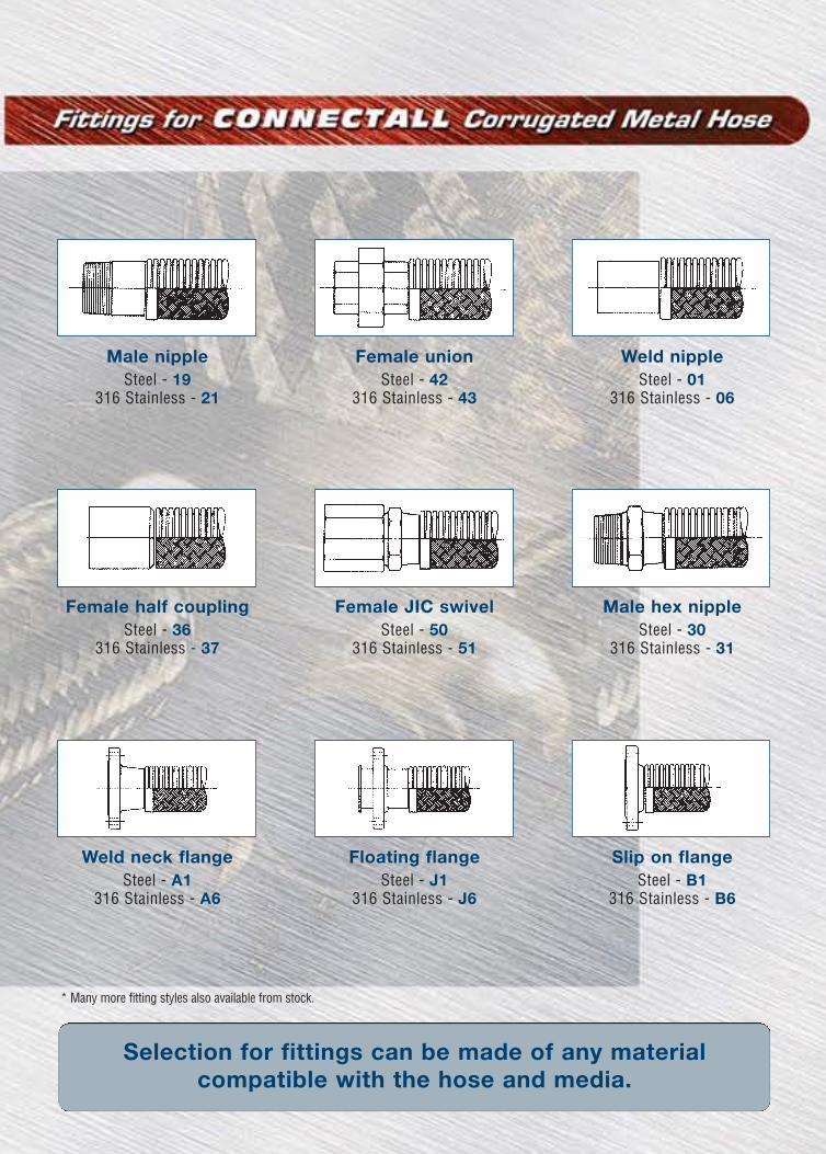
Male nippleSteel - 19
316 Stainless - 21
Female unionSteel - 42
316 Stainless - 43
Weld nippleSteel - 01
316 Stainless - 06
Female half couplingSteel - 36
316 Stainless - 37
Female JIC swivelSteel - 50
316 Stainless - 51
Male hex nippleSteel - 30
316 Stainless - 31
Weld neck flangeSteel - A1
316 Stainless - A6
Floating flangeSteel - J1
316 Stainless - J6
Slip on flangeSteel - B1
316 Stainless - B6
Selection for fittings can be made of any material compatible with the hose and media.
STYLE BB-19Nom. Dia. & Maximum Offset Maximum Working Pressure
Overall length (psig)(inch) Intermittent Static @ 70 °F @250 °F @ 400 °F
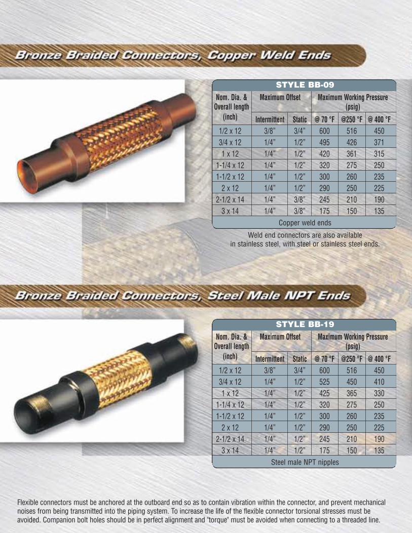
1/2 x 12 3/8” 3/4” 600 516 4503/4 x 12 1/4” 1/2” 525 450 4101 x 12 1/4” 1/2” 425 365 330
1-1/4 x 12 1/4” 1/2” 320 275 2501-1/2 x 12 1/4” 1/2” 300 260 235
2 x 12 1/4” 1/2” 290 250 2252-1/2 x 14 1/4” 1/2” 245 210 190
3 x 14 1/4” 1/2” 175 150 135Steel male NPT nipples
Flexible connectors must be anchored at the outboard end so as to contain vibration within the connector, and prevent mechanicalnoises from being transmitted into the piping system. To increase the life of the flexible connector torsional stresses must beavoided. Companion bolt holes should be in perfect alignment and "torque" must be avoided when connecting to a threaded line.
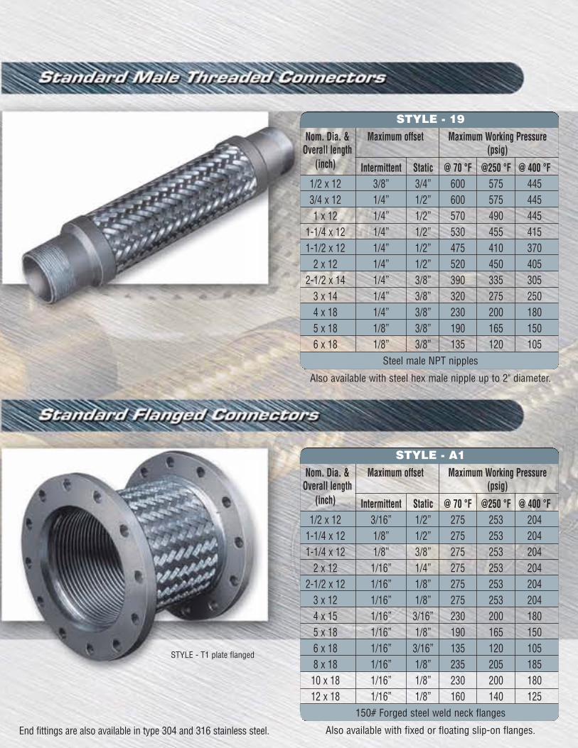
Nom. Dia. & Maximum offset Maximum Working PressureOverall length (psig)
(inch) Intermittent Static @ 70 °F @250 °F @ 400 °F1/2 x 12 3/8” 3/4” 600 575 4453/4 x 12 1/4” 1/2” 600 575 4451 x 12 1/4” 1/2” 570 490 445
1-1/4 x 12 1/4” 1/2” 530 455 4151-1/2 x 12 1/4” 1/2” 475 410 370
2 x 12 1/4” 1/2” 520 450 4052-1/2 x 14 1/4” 3/8” 390 335 305
3 x 14 1/4” 3/8” 320 275 2504 x 18 1/4” 3/8” 230 200 1805 x 18 1/8” 3/8” 190 165 1506 x 18 1/8” 3/8” 135 120 105
Steel male NPT nipples
Also available with steel hex male nipple up to 2" diameter.
STYLE - 19
End fittings are also available in type 304 and 316 stainless steel.
* Many more fitting styles also available from stock.STYLE - T1 plate flanged
STYLE - A1
Nom. Dia. & Maximum Offset Maximum Working PressureOverall length (psig)
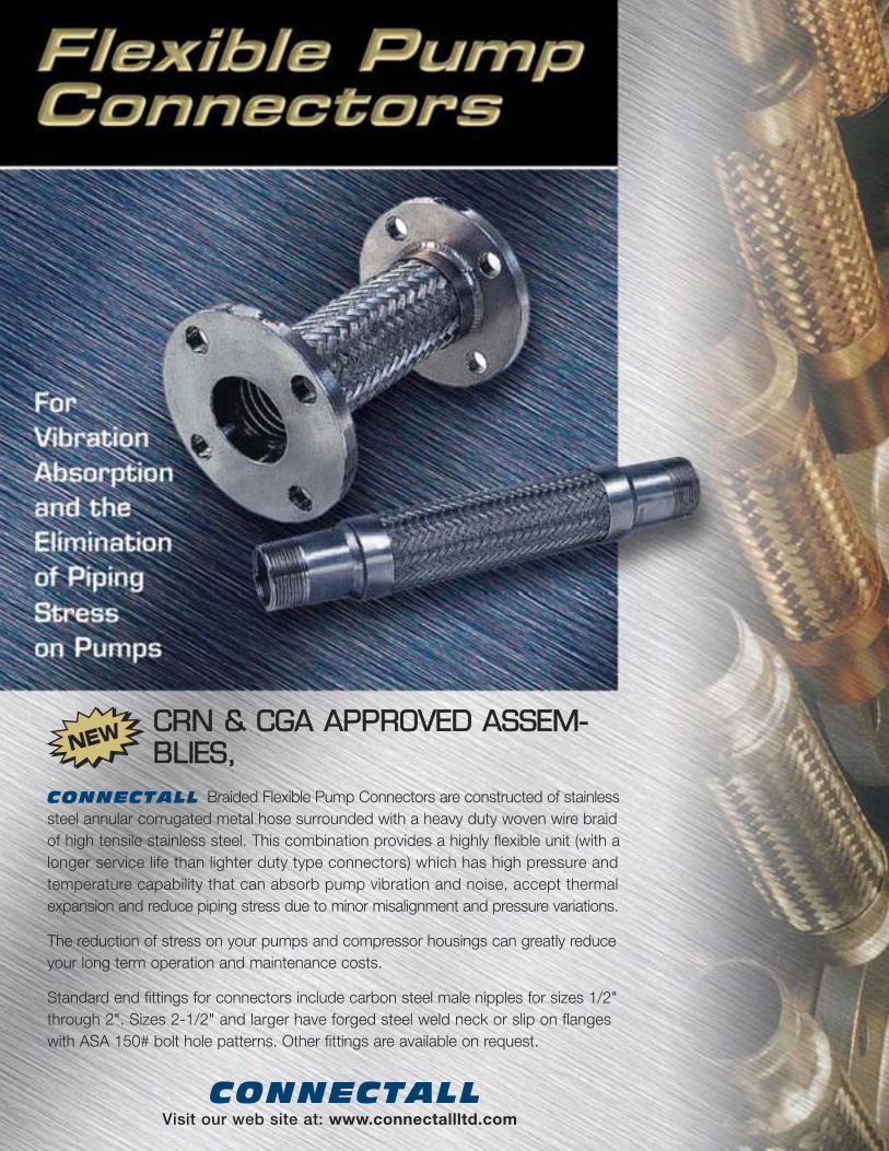
(inch) Intermittent Static @ 70 °F @250 °F @ 400 °F1/2 x 12 3/8” 3/4” 600 516 4503/4 x 12 1/4” 1/2” 495 426 3711 x 12 1/4” 1/2” 420 361 315
1-1/4 x 12 1/4” 1/2” 320 275 2501-1/2 x 12 1/4” 1/2” 300 260 235
2 x 12 1/4” 1/2” 290 250 2252-1/2 x 14 1/4” 3/8” 245 210 190
3 x 14 1/4” 3/8” 175 150 135Copper weld ends
Weld end connectors are also availablein stainless steel, with steel or stainless steel ends.
Nom. Dia. & Maximum offset Maximum Working PressureOverall length (psig)
(inch) Intermittent Static @ 70 °F @250 °F @ 400 °F1/2 x 12 3/16” 1/2” 275 253 204
1-1/4 x 12 1/8” 1/2” 275 253 2041-1/4 x 12 1/8” 3/8” 275 253 204
2 x 12 1/16” 1/4” 275 253 2042-1/2 x 12 1/16” 1/8” 275 253 204
3 x 12 1/16” 1/8” 275 253 2044 x 15 1/16” 3/16” 230 200 1805 x 18 1/16” 1/8” 190 165 1506 x 18 1/16” 3/16” 135 120 1058 x 18 1/16” 1/8” 235 205 18510 x 18 1/16” 1/8” 230 200 18012 x 18 1/16” 1/8” 160 140 125
150# Forged steel weld neck flanges
Also available with fixed or floating slip-on flanges.
STYLE BB-09
Male nippleSteel - 19
316 Stainless - 21
Female unionSteel - 42
316 Stainless - 43
Weld nippleSteel - 01
316 Stainless - 06
Female half couplingSteel - 36
316 Stainless - 37
Female JIC swivelSteel - 50
316 Stainless - 51
Male hex nippleSteel - 30
316 Stainless - 31
Weld neck flangeSteel - A1
316 Stainless - A6
Floating flangeSteel - J1
316 Stainless - J6
Slip on flangeSteel - B1
316 Stainless - B6
Selection for fittings can be made of any material compatible with the hose and media.
STYLE BB-19Nom. Dia. & Maximum Offset Maximum Working Pressure
Overall length (psig)(inch) Intermittent Static @ 70 °F @250 °F @ 400 °F
1/2 x 12 3/8” 3/4” 600 516 4503/4 x 12 1/4” 1/2” 525 450 4101 x 12 1/4” 1/2” 425 365 330
1-1/4 x 12 1/4” 1/2” 320 275 2501-1/2 x 12 1/4” 1/2” 300 260 235
2 x 12 1/4” 1/2” 290 250 2252-1/2 x 14 1/4” 1/2” 245 210 190
3 x 14 1/4” 1/2” 175 150 135Steel male NPT nipples
Flexible connectors must be anchored at the outboard end so as to contain vibration within the connector, and prevent mechanicalnoises from being transmitted into the piping system. To increase the life of the flexible connector torsional stresses must beavoided. Companion bolt holes should be in perfect alignment and "torque" must be avoided when connecting to a threaded line.
Nom. Dia. & Maximum offset Maximum Working PressureOverall length (psig)
(inch) Intermittent Static @ 70 °F @250 °F @ 400 °F1/2 x 12 3/8” 3/4” 600 575 4453/4 x 12 1/4” 1/2” 600 575 4451 x 12 1/4” 1/2” 570 490 445
1-1/4 x 12 1/4” 1/2” 530 455 4151-1/2 x 12 1/4” 1/2” 475 410 370
2 x 12 1/4” 1/2” 520 450 4052-1/2 x 14 1/4” 3/8” 390 335 305
3 x 14 1/4” 3/8” 320 275 2504 x 18 1/4” 3/8” 230 200 1805 x 18 1/8” 3/8” 190 165 1506 x 18 1/8” 3/8” 135 120 105
Steel male NPT nipples
Also available with steel hex male nipple up to 2" diameter.
STYLE - 19
End fittings are also available in type 304 and 316 stainless steel.
* Many more fitting styles also available from stock.STYLE - T1 plate flanged
STYLE - A1
Nom. Dia. & Maximum Offset Maximum Working PressureOverall length (psig)
(inch) Intermittent Static @ 70 °F @250 °F @ 400 °F1/2 x 12 3/8” 3/4” 600 516 4503/4 x 12 1/4” 1/2” 495 426 3711 x 12 1/4” 1/2” 420 361 315
1-1/4 x 12 1/4” 1/2” 320 275 2501-1/2 x 12 1/4” 1/2” 300 260 235
2 x 12 1/4” 1/2” 290 250 2252-1/2 x 14 1/4” 3/8” 245 210 190
3 x 14 1/4” 3/8” 175 150 135Copper weld ends
Weld end connectors are also availablein stainless steel, with steel or stainless steel ends.
Nom. Dia. & Maximum offset Maximum Working PressureOverall length (psig)
(inch) Intermittent Static @ 70 °F @250 °F @ 400 °F1/2 x 12 3/16” 1/2” 275 253 204
1-1/4 x 12 1/8” 1/2” 275 253 2041-1/4 x 12 1/8” 3/8” 275 253 204
2 x 12 1/16” 1/4” 275 253 2042-1/2 x 12 1/16” 1/8” 275 253 204
3 x 12 1/16” 1/8” 275 253 2044 x 15 1/16” 3/16” 230 200 1805 x 18 1/16” 1/8” 190 165 1506 x 18 1/16” 3/16” 135 120 1058 x 18 1/16” 1/8” 235 205 18510 x 18 1/16” 1/8” 230 200 18012 x 18 1/16” 1/8” 160 140 125
150# Forged steel weld neck flanges
Also available with fixed or floating slip-on flanges.
CCRRNN && CCGGAA AAPPPPRROOVVEEDD AASSSSEEMM--BBLLIIEESS,,
Braided Flexible Pump Connectors are constructed of stainlesssteel annular corrugated metal hose surrounded with a heavy duty woven wire braidof high tensile stainless steel. This combination provides a highly flexible unit (with alonger service life than lighter duty type connectors) which has high pressure andtemperature capability that can absorb pump vibration and noise, accept thermalexpansion and reduce piping stress due to minor misalignment and pressure variations.
The reduction of stress on your pumps and compressor housings can greatly reduceyour long term operation and maintenance costs.
Standard end fittings for connectors include carbon steel male nipples for sizes 1/2"through 2". Sizes 2-1/2" and larger have forged steel weld neck or slip on flangeswith ASA 150# bolt hole patterns. Other fittings are available on request.
Expansion JointsExpansion joints absorb movement in piping caused by thermal changes.Superior designs, manufacturing and extensive testing techniques assure you,our customer, of purchasing the best expansion joint being offered today.
Teflon HoseTeflon hose is extruded, then covered by a bronze or stainless steel wire reinforcing braid. Smooth bore and convoluted Teflon hose is lightweight andinert to most chemicals; it can be used for conveying liquids and gases.
Stainless Steel FittingsSSP fittings manufactures precision screw machine products and is an ISO-9001 certified designer and manufacturer of hydraulic fittings. Stainless steelconnectors, adapters and fittings available from stock.
Stripwound HoseStripwound hose is manufactured by spirally winding a preformed continuousmetal strip. It is used for conveying oils, tar, asphalt, steam and exhaust fumes;also for dry product transfer, or as a protective armor.
Hose, Ducts & ConnectorsMade of silicones, neoprenes and other elastomers for the movement of air,liquids or flowable solids, transportation, chemical processing and maintenanceneeds of industry throughout the world.
Industrial Tube & Pipe FittingsComplete range of industrial tube and pipe fittings manufactured to meet SAEand Military Standards. Methods of manufacturing include: hot forging, hotforming and screw machining from extruded bar stock from steel, brass orstainless steel.
Head Office
4291 Garand StreetMontreal, QuebecH4R 2B4, CanadaToll Free:Tel.: 877-335-7755Fax: 877-335-6504
established in 1994, registered ISO 9001:2000, is now a leading manufacturer of fluid conveying and connecting products. Our commitment to total quality, underlines our capability to provide excellent service and products to meet our clients most demanding needs.
Visit our web site at: www.connectallltd.com
NEWNEW
PressuresMaximum Working Pressure. The maximumoperating pressure to which a hose assemblyshould be subjected. It is normally computedat 25% of the design burst pressure.
Maximum Test Pressure. The maximumpressure to which a hose should be subjectedwithout harmful deformation. Normally computedat 150% of the working pressure.
Burst Pressure. The pressure at which thehose can be expected to fa i l . Computedbased upon installation in a straight line atroom temperature.
Shock and Pulsating Pressure. Whereshock or repetative pulsating pressures exist.The maximum allowed pressure shall notexceed 50% of the normal working pressure.
Pressure Drop. As a standard simplification,pressure drop through a corrugated metal hosecould average three times that of a steel pipedepending upon flow rate.
Flow Velocity. When the flow velocity exceeds50 ft./second liquid, 100 ft./second gas, inunbraided hose; or 75 ft./second liquid, 150ft./second gas in braided hose, an interlockliner should be used. The use of this linerwill increase the service life of the assemblyby reducing harmful resonance.
MotionsVibration. The vibration normally encounteredin industrial applications.
Discharge lines on pumps and compressorsalong with diesel engine exhaust are typicalvibration applications.
Random. Uncontrolled motion such as experi-enced by manual handling.
Continuous Flexing. A controlled cyclicalmotion based on a constant amount of travel.
Intermittent Flexing. Motion that occurs eitherregularly or irregularly along a path of full travel.
• Avoid hose twisting • Prevent out-of-plane flexing
• Respect bend radius • Always support piping
Key Installation RecommendationsDistributed By: