Embed Size (px)
Citation preview

NEWCREST’S INDUSTRY FIRST APPLICATION OF ERIEZ HYDROFLOATTM
TECHNOLOGY FOR COPPER RECOVERY FROM TAILINGS AT CADIA VALLEY
OPERATIONS
*L. Vollert, B. Akerstrom, and B. Seaman
NEWCREST MINING LTD
L8 600 St Kilda Rd, St Kilda, Australia 3182
(*Corresponding author: [email protected])
J. Kohmuench
ERIEZ MANUFACTURING COMPANY
2200 Asbury Rd, Erie, PA 16506
ABSTRACT
In August 2018, the first full-scale HydroFloatTM cells for the recovery of coarse composited copper
and gold were commissioned at Newcrest’s Cadia Valley operation in New South Wales, Australia. The
primary objective of the installation is to recover coarse value-bearing composites that are lost to
conventional flotation tailings, without the need for additional power input for particle size reduction to
improve mineral liberation. This paper examines the application of Eriez HydroFloatTM technology for the
recovery of coarse, poorly liberated copper sulphide particles drawing on recent experience from lab scale
testwork through circuit design and commissioning of the full-scale installation at Cadia Valley.
KEYWORDS
Coarse flotation, Copper, Flotation, HydroFloatTM, Newcrest
INTRODUCTION
In the face of declining copper head grades and a tightening regulatory environment around the use
of wet tailings dams, the processing of copper ores at coarser particle sizes has become a focal point for the
industry. Sulphide flotation using the Eriez HydroFloatTM is one of the emergent technologies that sits under
this umbrella of coarse pre-concentration. It has been demonstrated through numerous lab and pilot scale
testwork programs carried out by Newcrest and others (Awatey, Kohmuench, Thanasekaran, Skinner &
Zanin, 2013), to improve the flotation recovery of sulphide-rock composite particles with low surface
liberation, relative to conventional flotation technology.
The HydroFloatTM technology has been used widely for the recovery of coarse potash, phosphate,
coal, vermiculite, spodumene and diamonds but has never been applied at full scale in either gold or sulphide
flotation. In August 2018, the first full-scale 3.4 m diameter HydroFloatTM cells for the recovery of coarse
composite copper and gold were commissioned at Newcrest’s Cadia Valley operation in New South Wales.
The primary objective of the installation is to recover coarse value-bearing composite particles that are lost
to conventional flotation tailings, without the need for additional upfront power input for particle size
reduction to improve mineral liberation.
Composite particles have been identified as the principal carrier of copper in the Cadia concentrator
rougher tailings with approximately 45% of copper contained in the plus 106 µm size fraction and 90% of
those particles with less than 15% surface exposure of copper sulphide. The floatability of these composites
is controlled by the particle size coupled with the extent and texture of the hydrophobic surface of the exposed
sulphide mineral component (Fosu, 2014). This poor recovery of composite particles with low surface
exposure presented a significant opportunity for the application of HydroFloatTM technology in a scavenging
capacity.
RECOVERY OPPORTUNITY AT CADIA
The Cadia East ore body is a low-grade porphyry style copper-gold-molybdenum deposit. Copper
mineralogy is dominantly chalcopyrite and bornite with strong non-sulphide gangue mineral association.
There are two primary geo-metallurgical domains: 1) disseminated copper dominant mineralization which is
predominant near the surface, and 2) sheeted veining which is localized around a core of steeply dipping
sheeted quartz‐ calcite‐ bornite‐ chalcopyrite‐ molybdenite veins (Holliday et al., 2002).
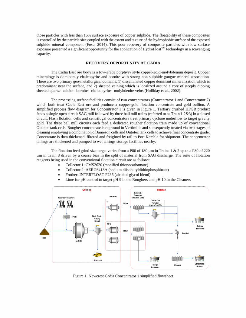
The processing surface facilities consist of two concentrators (Concentrator 1 and Concentrator 2)
which both treat Cadia East ore and produce a copper-gold flotation concentrate and gold bullion. A
simplified process flow diagram for Concentrator 1 is given in Figure 1. Tertiary crushed HPGR product
feeds a single open circuit SAG mill followed by three ball mill trains (referred to as Train 1,2&3) in a closed
circuit. Flash flotation cells and centrifugal concentrators treat primary cyclone underflow to target gravity
gold. The three ball mill circuits each feed a dedicated rougher flotation train made up of conventional
Outotec tank cells. Rougher concentrate is reground in Vertimills and subsequently treated via two stages of
cleaning employing a combination of Jameson cells and Outotec tank cells to achieve final concentrate grade.
Concentrate is then thickened, filtered and freighted by rail to Port Kembla for shipment. The concentrator
tailings are thickened and pumped to wet tailings storage facilities nearby.
The flotation feed grind size target varies from a P80 of 180 µm in Trains 1 & 2 up to a P80 of 220
µm in Train 3 driven by a coarse bias in the split of material from SAG discharge. The suite of flotation
reagents being used in the conventional flotation circuit are as follows:
Collector 1: CMS2620 (modified thionocarbamate)
Collector 2: AERO3418A (sodium diisobutyldithiophosphinate)
Frother: INTERFLOAT F236 (alcohol-glycol blend)
Lime for pH control to target pH 9 in the Roughers and pH 10 in the Cleaners
Figure 1. Newcrest Cadia Concentrator 1 simplified flowsheet
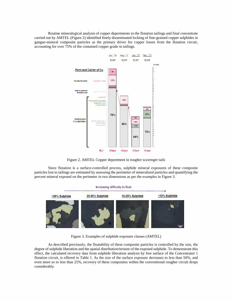
Routine mineralogical analysis of copper deportments in the flotation tailings and final concentrate
carried out by AMTEL (Figure 2) identified finely disseminated locking of fine-grained copper sulphides in
gangue-mineral composite particles as the primary driver for copper losses from the flotation circuit,
accounting for over 75% of the contained copper grade in tailings.
Figure 2. AMTEL Copper deportment in rougher scavenger tails
Since flotation is a surface-controlled process, sulphide mineral exposures of these composite
particles lost to tailings are estimated by assessing the perimeter of mineralized particles and quantifying the
percent mineral exposed on the perimeter in two dimensions as per the examples in Figure 3.
Figure 3. Examples of sulphide exposure classes (AMTEL)
As described previously, the floatability of these composite particles is controlled by the size, the
degree of sulphide liberation and the spatial distribution/texture of the exposed sulphide. To demonstrate this
effect, the calculated recovery data from sulphide liberation analysis by free surface of the Concentrator 1
flotation circuit, is offered in Table 1. As the size of the surface exposure decreases to less than 50%, and
even more so to less than 25%, recovery of these composites within the conventional rougher circuit drops
considerably.
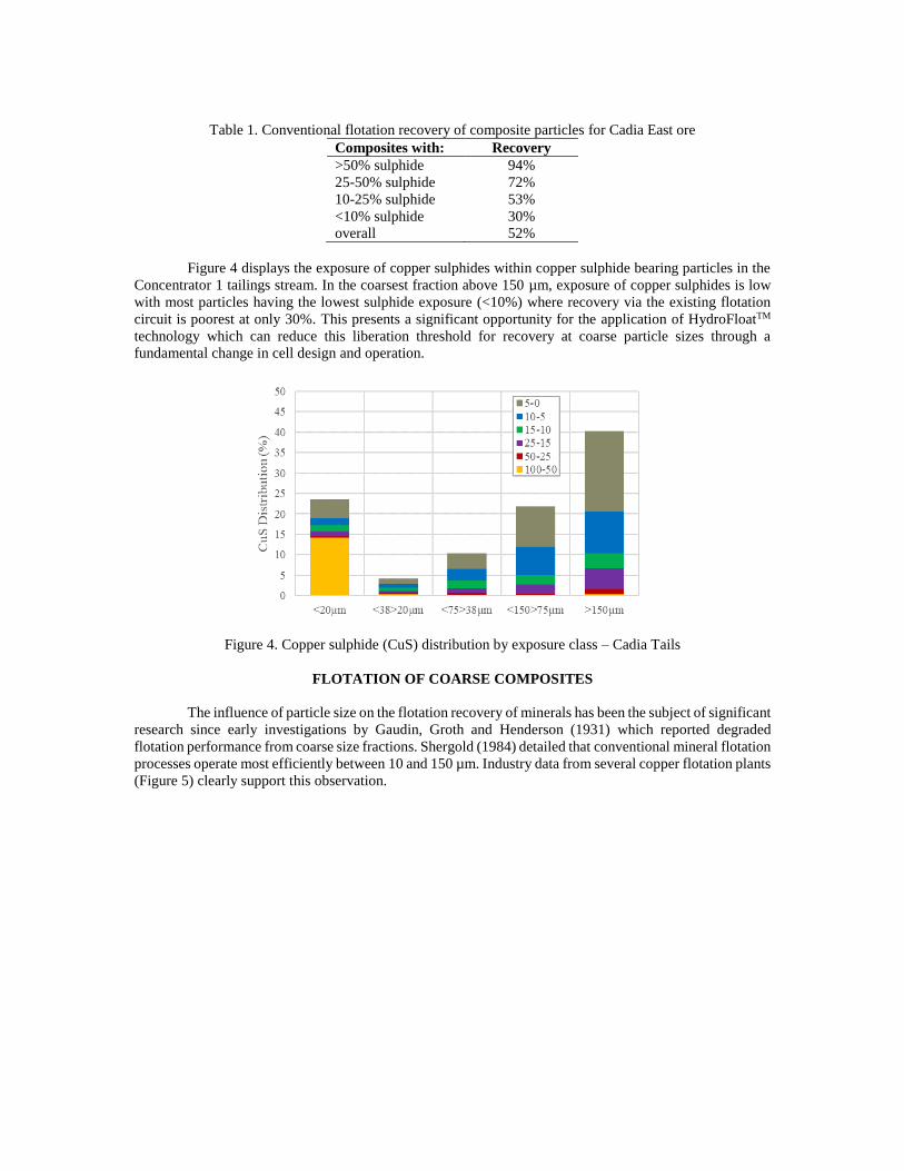
Table 1. Conventional flotation recovery of composite particles for Cadia East ore
Composites with: Recovery
>50% sulphide 94%
25-50% sulphide 72%
10-25% sulphide 53%
<10% sulphide 30%
overall 52%
Figure 4 displays the exposure of copper sulphides within copper sulphide bearing particles in the
Concentrator 1 tailings stream. In the coarsest fraction above 150 µm, exposure of copper sulphides is low
with most particles having the lowest sulphide exposure (<10%) where recovery via the existing flotation
circuit is poorest at only 30%. This presents a significant opportunity for the application of HydroFloatTM
technology which can reduce this liberation threshold for recovery at coarse particle sizes through a
fundamental change in cell design and operation.
Figure 4. Copper sulphide (CuS) distribution by exposure class – Cadia Tails
FLOTATION OF COARSE COMPOSITES
The influence of particle size on the flotation recovery of minerals has been the subject of significant
research since early investigations by Gaudin, Groth and Henderson (1931) which reported degraded
flotation performance from coarse size fractions. Shergold (1984) detailed that conventional mineral flotation
processes operate most efficiently between 10 and 150 µm. Industry data from several copper flotation plants
(Figure 5) clearly support this observation.
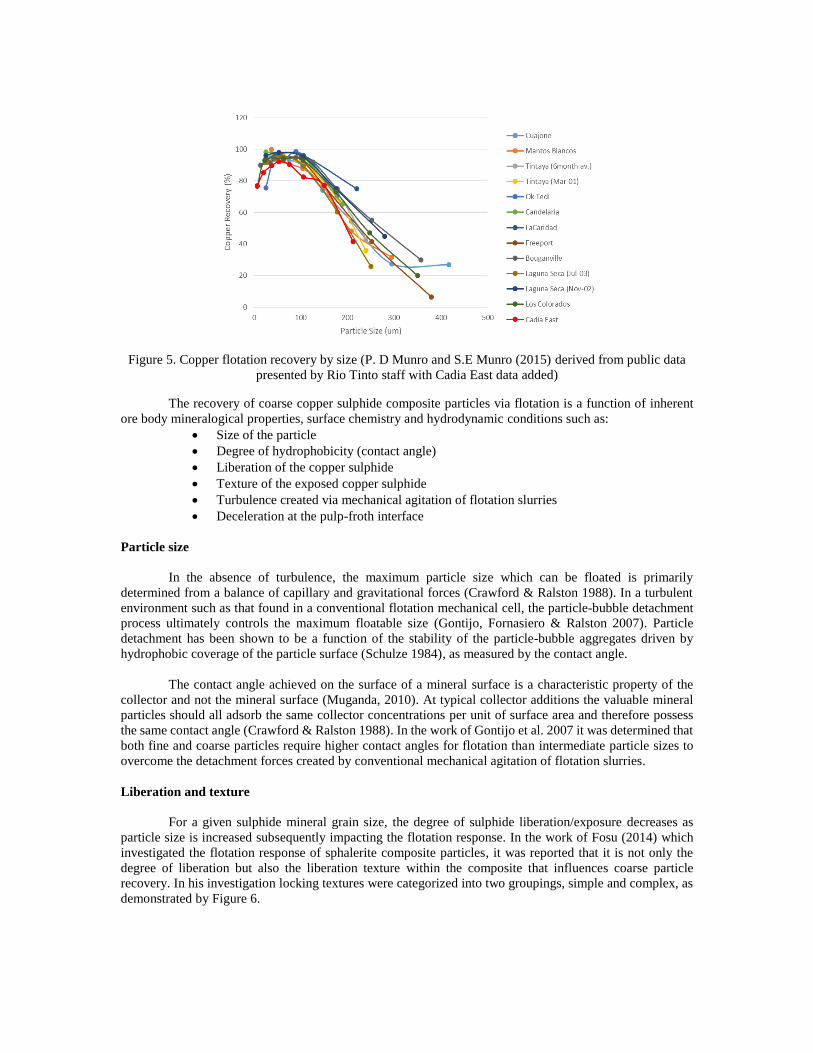
Figure 5. Copper flotation recovery by size (P. D Munro and S.E Munro (2015) derived from public data
presented by Rio Tinto staff with Cadia East data added)
The recovery of coarse copper sulphide composite particles via flotation is a function of inherent
ore body mineralogical properties, surface chemistry and hydrodynamic conditions such as:
Size of the particle
Degree of hydrophobicity (contact angle)
Liberation of the copper sulphide
Texture of the exposed copper sulphide
Turbulence created via mechanical agitation of flotation slurries
Deceleration at the pulp-froth interface
Particle size
In the absence of turbulence, the maximum particle size which can be floated is primarily
determined from a balance of capillary and gravitational forces (Crawford & Ralston 1988). In a turbulent
environment such as that found in a conventional flotation mechanical cell, the particle-bubble detachment
process ultimately controls the maximum floatable size (Gontijo, Fornasiero & Ralston 2007). Particle
detachment has been shown to be a function of the stability of the particle-bubble aggregates driven by
hydrophobic coverage of the particle surface (Schulze 1984), as measured by the contact angle.
The contact angle achieved on the surface of a mineral surface is a characteristic property of the
collector and not the mineral surface (Muganda, 2010). At typical collector additions the valuable mineral
particles should all adsorb the same collector concentrations per unit of surface area and therefore possess
the same contact angle (Crawford & Ralston 1988). In the work of Gontijo et al. 2007 it was determined that
both fine and coarse particles require higher contact angles for flotation than intermediate particle sizes to
overcome the detachment forces created by conventional mechanical agitation of flotation slurries.
Liberation and texture
For a given sulphide mineral grain size, the degree of sulphide liberation/exposure decreases as
particle size is increased subsequently impacting the flotation response. In the work of Fosu (2014) which
investigated the flotation response of sphalerite composite particles, it was reported that it is not only the
degree of liberation but also the liberation texture within the composite that influences coarse particle
recovery. In his investigation locking textures were categorized into two groupings, simple and complex, as
demonstrated by Figure 6.

Figure 6. Composite particles with simple and complex locking texture (Fosu, 2014)
The testwork demonstrated a difference in recoverability of sphalerite bearing particles with varying
locking textures. A simple locking texture gave higher recovery than a complex locking texture for an
equivalent overall degree of liberation. It was theorized that this effect may be driven by the bubble contact
with the exposed mineral surface, a simple texture would conceptually provide more continuous surface area
for attachment.
Hydrodynamic conditions
A mechanical flotation cell consists of three hydrodynamic zones to achieve effective mineral
flotation, namely:
1. a turbulent zone created by the impeller/stator arrangement to simultaneously achieve solids
suspension, dispersion of gas and bubble-particle contacting.
2. a quiescent zone where bubble-particle aggregates rise though the pulp, and
3. a froth zone which aids in the separation of valuable bubble-particle aggregates from gangue
particles suspended in the interstitial water between the bubbles.
Coarse composite particles of low hydrophobic surface expression are highly susceptible to
detachment due to the stability of the bubble-particle aggregate as discussed above. The presence of multiple
zones within the same unit operation is detrimental to coarse composite flotation. Particle detachment can
occur during acceleration or collisions in the turbulent zone created by the impeller as well as at the pulp-
froth interface due to the change in momentum of bubble-particle aggregates striking the interface (Seaman,
2006).
ERIEZ HYDROFLOAT TECHNOLOGY
It is evident from the prior research carried out, that to effectively float coarse particles a
predominately quiescent flotation environment and elimination of the froth phase is required. In the early
2000’s, the HydroFloatTM separator was developed by Eriez specifically to address these requirements and
maximise coarse particle recovery (Mankosa and Luttrell, 2002).
The HydroFloatTM cell works on combining the principals of flotation with hindered settling. The
key characteristic of the HydroFloat™ cell is the presence of an aerated fluidized bed. Using this approach,
deslimed, reagentised feed from a classification stage is introduced into the top of the separator via a feedwell
at approximately 60% solids, by weight. The fluidization water, air and frother is injected through a
cavitation tube to generate fine bubbles and then conveyed into a distribution manifold located around the
midpoint of the unit. With fine bubbles being introduced directly into the fluidized bed the probability of
bubble-particle collision can be enhanced.

Bubble attachment reduces the relative density of the resulting bubble-particle aggregates allowing
them to be separated out of the fluidized bed. Mineralised particles either float immediately or are collected
on the teeter-bed surface until sufficient bubbles accumulate to assist with hydraulic transfer to the overflow
launder for collection as concentrate. It is common to observe flocs or rafts of multiple coarse particles and
bubbles floating together in concentrate. A simple schematic of the HydroFloatTM is included in Figure 7.
Figure 7. Schematic of the Eriez HydroFloat (after Kohmuench, Mankosa, Thanasekaran & Hobert, 2018)
Due to the upwards flow of the teeter water continually overflowing the lip of the cell, there is no
froth zone of discernable depth present during steady-state operation. Fine bubbles with attached coarse
particles are readily observed overflowing with the fluidization water into the concentrate launder as seen in
Figure 8 which is a photo from one of the HydroFloatTM cells at Cadia.
Figure 8. Concentrate overflowing a HydroFloat cell at Cadia
The key HydroFloatTM operating parameters that are adjusted to influence concentrate recovery and
grade are fluidised bed depth, fluidised bed density (measured by the pressure differential and controlled
with the water rate) and air addition:

The depth of the fluidised bed (from the cell lip to the top of the bed/water interface) is measured
via a ball float and striker plate arrangement which is calibrated during commissioning to sit on top
of bed. A higher bed level (i.e., deeper bed), with all other parameters equal, has been found to
produce increased recovery at a lower concentrate grade. This effect is related to a reduction in the
distance particles need to travel to reach the overflowing surface, reducing the probability of drop-
back.
The bed density is adjusted through changes in the fluidisation water rate which augments the
degree of bed expansion. Bed density is determined from the differential pressure measured between
two pressure transmitters installed at a known distance apart within the fluidised bed zone.
Insufficient bed expansion (low fluidisation water rate) will result in bubbles and particles being
unable to flow though the bed which causes channelling and turbulence which reduces recovery.
Over expansion (high fluidisation water rate) will cause hydraulic entrainment and unselectively
carry a significant portion of the mass in finer particle sizes to the concentrate, which reduces
concentrate grade. There is an interaction between bed depth and fluidisation water rate that must
be considered when tuning the control loops around the HydroFloatTM units.
Air is added as a fixed volumetric ratio to the total air + water flow so that air addition rate increases
for a given increase in water rate. Typical ratios are in the range of 15—20% v/v. Excessive air
flowrates may result in reduced bed residence times and turbulence. Extremely high rates may
prevent a stable teeter bed from forming altogether.
LABORATORY AND PILOT TESTWORK
Laboratory and pilot plant testwork programs were undertaken to assess the metallurgical
performance of the HydroFloat™ cell on Cadia East ore and demonstrate the ability to effectively recover
coarse composite particles with low surface expression. This included two programs:
Sighter testing with a 16” CrossFlowTM separator and 12” HydroFloatTM at Cadia in October 2015.
6” HydroFloatTM laboratory testwork at ALS Kamloops in 2016 on Cadia East ore and tailings
samples.
In October 2015, the HydroFloatTM sighter testwork for tailings scavenging was commenced onsite
off the back of promising results from laboratory testwork on feed samples. The equipment was installed on
the Train 3 tailings thickener, drawing feed out of the distribution box. Siphoned rougher scavenger tailings
was fed to an Eriez CrossFlowTM classifier to remove fine material (-106μm). The coarse underflow reported
to a conditioning tank where reagents, Potassium Amyl Xanthate (PAX) and 3418A, were added prior to
flotation in the HydroFloatTM cell.
The CrossFlow™ classifier was found to be undersized for the pilot duty which led to issues in
operation, resulting in misplacement of -150 μm fines to the coarse underflow stream. This resulted in higher
mass recoveries in the downstream pilot HydroFloat™ separator which were reported well above target.
Despite the issues, size-by-size recovery analysis on the survey data collected demonstrated that the
HydroFloatTM was able to recover coarse composite particles being missed by the conventional cells, with
31% of the copper and 28% of the gold in the fraction greater than 150 μm recovered with only 3% of the
mass.
To further optimise recovery, 500 kg of rougher scavenger tailings from the Train 3 flotation circuit
was collected in February 2016 for laboratory HydroFloatTM testwork at ALS Kamloops. The sample was
screened at 106 µm with some of the fines re-introduced to generate a pseudo classifier underflow stream
for the testwork. This sample was reflective of a typical tails stream at the time with the plant operating at a
grind size of 120 µm. A single conventional flotation test and a series of HydroFloatTM tests were conducted
on the prepared tailings sample using PAX as the collector and emulsified diesel as a collector extender.
Copper, Sulphur and mass recovery by size data is displayed in Figure 9 for the optimized conditions.
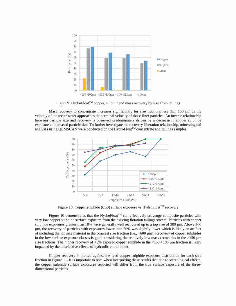
Figure 9. HydroFloatTM copper, sulphur and mass recovery by size from tailings
Mass recovery to concentrate increases significantly for size fractions less than 150 µm as the
velocity of the teeter water approaches the terminal velocity of those finer particles. An inverse relationship
between particle size and recovery is observed predominately driven by a decrease in copper sulphide
exposure at increased particle size. To further investigate the recovery-liberation relationship, mineralogical
analyses using QEMSCAN were conducted on the HydroFloatTM concentrate and tailings samples.
Figure 10. Copper sulphide (CuS) surface exposure vs HydroFloatTM recovery
Figure 10 demonstrates that the HydroFloatTM can effectively scavenge composite particles with
very low copper sulphide surface exposure from the existing flotation tailings stream. Particles with copper
sulphide exposures greater than 10% were generally well recovered up to a top size of 300 μm. Above 300
μm, the recovery of particles with exposures lower than 50% was slightly lower which is likely an artifact
of including the top size material in the coarsest size fraction (i.e., +600 µm). Recovery of copper sulphides
in the low surface exposure classes is good considering the relatively low mass recoveries in the >150 μm
size fractions. The higher recovery of <5% exposed copper sulphide in the <150 >106 μm fraction is likely
impacted by the unselective effects of hydraulic entrainment.
Copper recovery is plotted against the feed copper sulphide exposure distribution for each size
fraction in Figure 11. It is important to note when interpreting these results that due to stereological effects,
the copper sulphide surface exposures reported will differ from the true surface exposure of the three-
dimensional particles.

Figure 11. Copper sulphide (CuS) exposure distribution by size with copper recovery overlaid
The data suggest that by applying the HydroFloatTM technology to Cadia East tailings the minimum
required surface exposure to achieve flotation across size fractions up to 300 µm can be shifted to less than
5%. A composite Back Scatter Electron (BSE) image of HydroFloat 300 × 200 µm concentrate with
chalcopyrite occurrences shown in green, displayed in Figure 12, assists with visualising the low surface
exposure present on the particles that were recovered.
Figure 12. HydroFloat concentrate <300>212 μm, examples of Chalcopyrite occurrences
FULL SCALE PLANT
Circuit design
Following successful testwork results, conceptual level study work was carried out to assess the
options for a full-scale installation of HydroFloatTM cells within the Cadia flowsheet. Scavenging of the
existing rougher tailings stream presented a unique opportunity to demonstrate the technology in a lower risk
environment whilst still delivering a robust economic case.
Efficient classification of the tailings stream at the time was considered crucial to the success of the
HydroFloatTM circuit and formed the basis of the flowsheet options investigated. A total of three options for
circuit configurations were considered during the preliminary engineering stage.
Option 1 - Primary and secondary cycloning followed by HydroFloatTM
Option 2 - Primary cycloning followed by CrossFlowTM and HydroFloatTM
Option 3 – Primary and secondary cycloning followed by CrossFlowTM and HydroFloatTM
Some of the key criteria considered when assessing each potential option are as follows:
Ability to easily bypass the circuit without impacting the upstream process.
A primary bank of cyclones is better equipped to conduct the initial classification stage as it will
cope with the total circuit volume and any process fluctuations better than a teeter-bed separator.
Water supply requirements for each classification option needs to be considered along with any
downstream processing requirements associated with the additional flowrates.
Utilising cyclone underflow as feed to the HydroFloatTM cells added significant risk to the
separation process as it was largely untested.
Utilising a CrossFlow classifier within the classification circuit will minimise the misplacement of
fines to the coarse underflow which in turn reduces the mass of misplaced fines that will ultimately
be entrainment to the HydroFloatTM concentrate.
High fines content in the HydroFloatTM product would require additional regrind circuit capacity.
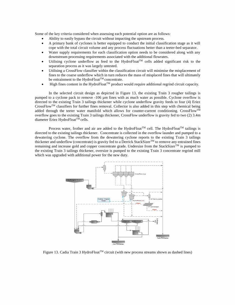
In the selected circuit design as depicted in Figure 13, the existing Train 3 rougher tailings is
pumped to a cyclone pack to remove -106 µm fines with as much water as possible. Cyclone overflow is
directed to the existing Train 3 tailings thickener while cyclone underflow gravity feeds to four (4) Eriez
CrossFlowTM classifiers for further fines removal. Collector is also added in this step with chemical being
added through the teeter water manifold which allows for counter-current conditioning. CrossFlowTM
overflow goes to the existing Train 3 tailings thickener, CrossFlow underflow is gravity fed to two (2) 3.4m
diameter Eriez HydroFloatTM cells.
Process water, frother and air are added to the HydroFloatTM cell. The HydroFloatTM tailings is
directed to the existing tailings thickener. Concentrate is collected in the overflow launder and pumped to a
dewatering cyclone. The overflow from the dewatering cyclone reports to the existing Train 3 tailings
thickener and underflow (concentrate) is gravity fed to a Derrick StackSizerTM to remove any entrained fines
remaining and increase gold and copper concentrate grade. Undersize from the StackSizerTM is pumped to
the existing Train 3 tailings thickener, oversize is pumped to the existing Train 3 concentrate regrind mill
which was upgraded with additional power for the new duty.
Figure 13. Cadia Train 3 HydroFloatTM circuit (with new process streams shown as dashed lines)
De-bottlenecking
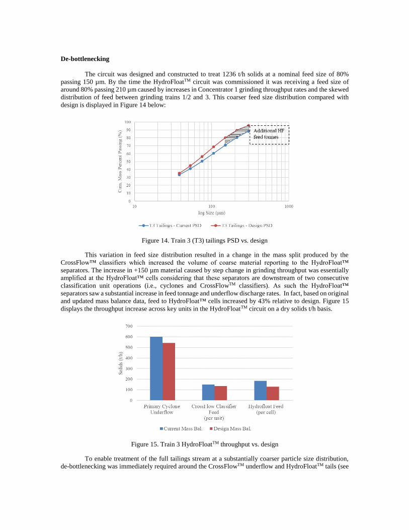
The circuit was designed and constructed to treat 1236 t/h solids at a nominal feed size of 80%
passing 150 µm. By the time the HydroFloatTM circuit was commissioned it was receiving a feed size of
around 80% passing 210 µm caused by increases in Concentrator 1 grinding throughput rates and the skewed
distribution of feed between grinding trains 1/2 and 3. This coarser feed size distribution compared with
design is displayed in Figure 14 below:
Figure 14. Train 3 (T3) tailings PSD vs. design
This variation in feed size distribution resulted in a change in the mass split produced by the
CrossFlow™ classifiers which increased the volume of coarse material reporting to the HydroFloat™
separators. The increase in +150 µm material caused by step change in grinding throughput was essentially
amplified at the HydroFloat™ cells considering that these separators are downstream of two consecutive
classification unit operations (i.e., cyclones and CrossFlowTM classifiers). As such the HydroFloat™
separators saw a substantial increase in feed tonnage and underflow discharge rates. In fact, based on original
and updated mass balance data, feed to HydroFloat™ cells increased by 43% relative to design. Figure 15
displays the throughput increase across key units in the HydroFloatTM circuit on a dry solids t/h basis.
Figure 15. Train 3 HydroFloatTM throughput vs. design
To enable treatment of the full tailings stream at a substantially coarser particle size distribution,
de-bottlenecking was immediately required around the CrossFlowTM underflow and HydroFloatTM tails (see

Figure 16 below). This was achieved via retrofitting the CrossFlow™ classifiers with existing full trim, 4-
inch SlurryFlo valves, previously installed on the HydroFloatTM separators, and the installation of larger 6-
inch, full trim SlurryFlo valves and modified lower cone sections to the HydroFloatTM cells.
Figure 16. T3 HydroFloat PFD with bottlenecks highlighted
This increase in throughput resulted in an increase the solids loading/unit area in the HydroFloatTM
cells from 15 up to 22 t/h/m^2, which is at the upper end of the recommended operating range according to
the Eriez. The stability of the fluidized bed and consistency of material flow must be investigated while
operating at these elevated superficial rates. Further, the impact on recovery has not been fully explored at
this stage. The relationship between residence time and recovery for conventional approaches is well known;
however, the theory of operation driving the HydroFloatTM cell is much different than that found in
conventional flotation. In this device, valuable particles are not necessarily flushed through the separator at
higher rates but can be retained and accumulate at the zone atop the fluidised bed until they have sufficient
bubble attachment to float, meaning that the residence time for these particles can be extended relative to the
bulk solids.
Commissioning & optimisation
A total of 30 sets of survey data were collected during commissioning. Most of these involved
sampling around the HydroFloatTM unit only, with a few full and half circuit surveys included. Because these
surveys were conducted during start-up and commissioning, they cover a wide range of feed rates, circuit
stability, feed particle size distributions and operating parameters.
Although, optimization of the circuit and operating parameters is ongoing, Figure 17 displays the
gold and copper recovery around the HydroFloatTM unit for each set of survey data calculated from
HydroFloatTM feed, concentrate and tails assays using the two-product formula.

Figure 17. HydroFloat™ survey unit recovery data
The dashed lines display the gold and copper recovery targets based on HydroFloat™ recovery by
size parameters from the various test work programs. The green diamonds give the HydroFloatTM feed P80
at the time of the survey. In the data presented the CrossFlows™ classifiers are cutting coarser than modelled
resulting in a coarser particle size distribution in the HydroFloat™ feed. As there is no size-by-assay data
available yet, the survey data presented above is the total recovery across all size fractions.
During the start-up, the PAX plant was not yet complete, and an alternate reagent was utilized. As
such dosing was both inconsistent and not optimized. Further, the circuit has seen large fluctuations in feed
size distributions to the HydroFloat™ separators. In fact, during surveys 26 through 30, the feed became
much coarser which resulted in lower recoveries while making no changes in the HydroFloat™ operating
parameters to counteract. As such, the operating parameters of the HydroFloat™ separators (e.g., bed depth,
bed density, and aeration rate), must be fully investigated during the next phase of optimization. The aim of
which will be to determine the best operating approach to maximize recovery while providing consistent and
robust performance. Regardless of the variability seen in performance during the initial start-up and
commissioning phase, the coarse tailings scavenging circuit has been able to achieve results approaching
and, in some cases, exceeding the initial targets.
CONCLUSIONS
Newcrest has successfully commissioned the first full-scale HydroFloatTM cells for the recovery of
coarse composited sulphide and gold from flotation tailings, though optimization work will continue for
some time. The tailings scavenger installation on Trian 3 in Concentrator 1 at Cadia Valley operations is
considered a low-risk, full-scale trial of fluidized-bed flotation technology to provide the confidence for
Newcrest to proceed with other tailings installations and/or installations aimed at early gangue rejection from
the primary grinding circuit.
With the introduction of coarse particle flotation using the HydroFloatTM technology, recovery is
not only increased for a given grind size, but also sustained at coarser grind sizes. In traditional copper
concentrators, there is always a trade-off between recovery and grind size. As primary grind size is decreased,
more power is consumed per tonne of ore resulting in a lower throughput rate for a given installed power. It
has been demonstrated that the application of coarse flotation technology such as the HydroFloatTM has the
ability to shift the economic optimum grind size and increase cash flow.

REFERENCES
Awatey, B., Thanasekaran, H., Kohmuench, J.N., Skinner, W. & Zanin, M. (2013). Optimization of operating
parameter for coarse sphalerite flotation in the HydroFloat fluidised-bed separator. Minerals
Engineering, 50–51, 99–105.
Carmona Franco, J.J., Fernanda Castillo, M.F., Concha, J., Christodoulou, L. & Wasmund, E.B. (2015).
Coarse Gold Recovery Using Flotation in a Fluidized Bed. Proceedings of Canadian Minerals
Processors Conference, Ontario, Canada.
Fan, L.S., Jean, R.H. & Kitano, K. (1987). On the operating regimes of cocurrent upward gas-liquid-solid
systems with liquid as the continuous phase. Chemical Engineering Science 42, 1853–1855.
Fosu, S. (2014). Synthesis and characterisation of composite particles with respect to flotation (Doctoral
Dissertation). Ian Wark Research Institute, University of South Australia, Adelaide.
Gaudin, A., Groh, J.O & Henderson, H. (1931). Effect of particle size on flotation. Technical Publication,
no. 414.
Gontijo, C. de F., Fornasiero, D. & Ralston, J. (2007). The Limits of Fine and Coarse Particle Flotation, The
Canadian Journal of Chemical Engineering, vol. 85 no. 5, 739–747.
Holliday, J.R., Wilson, A.J., Blevin, P.L., Tedder, I.J., Dunham, P.D. & Pfitzner, M. (2002). Porphyry gold
copper mineralisation in the Cadia district, eastern Lachlan Fold Belt, New South Wales, and its
relationship to shoshonitic magmatism. Mineralium Deposita, 37, 100–116.
Kohmuench, J., Mankosa, M., Yan, E., Wyslouzil, H., Christodoulou, L., & Luttrell, G.H. (2010). Advances
in coarse particle recovery - fluidised-bed flotation. XXV International Mineral Processing
Congress, Brisbane, Australia, 2065–2076.
Kohmuench, J., Mankosa, M., Thanasekaran, H. & Hobert, A. (2018). Improving coarse particle flotation
using the HydroFloatTM (raising the trunk of the elephant curve). Minerals Engineering, 121, 137–
145.
Kohmuench, J.N., Thanasekaran, H., Mankosa, M.J. & Luttrell G.H. (2016). The Impact of Fluidised-Bed
Flotation for Treating Coarse Sulphides. 13th AusIMM Mill Operators’ Conference 2016, Townsville, Australia, Paper Number: 008.
Mankosa, M.J. & Luttrell, G.H. (2002). Air-assisted density separator device and method, U.S Patent
6,425,485, July 30, 2002.
Munro, P. D & Munro, S.E, (2015). Observations on Cadia Valley concentrator operations (Newcrest
internal report. Unpublished).
Seaman, D. (2006). Selective transport of attached particles across the froth phase (Doctoral Dissertation).
School of Engineering, University of Queensland, Queensland.
Shergold, H. (1984). Flotation in Mineral Processing. In K. J. Ives (Ed.), The Scientific Basis of Flotation
(pp. 229–287).
Trahar, J. (1981). A rational interpretation of the role of particle size in flotation. International Journal of
Mineral Processing, vol. 8, no. 4, 289–327.