Embed Size (px)
Citation preview
RULES FOR CLASSIFICATION OF
The content of thisaccepts that it is pverification servicepursuant to this docconsequences arisin
The electronic p
Ships
PART 6 CHAPTER 20
NEWBUILDINGSSPECIAL EQUIPMENT AND SYSTEMS – ADDITIONAL CLASS
Nautical Safety – Offshore Service Vessels
JANUARY 2012
DET NORSKE VERITAS AS
service document is the subject of intellectual property rights reserved by Det Norske Veritas AS (DNV). The userrohibited by anyone else but DNV and/or its licensees to offer and/or perform classification, certification and/ors, including the issuance of certificates and/or declarations of conformity, wholly or partly, on the basis of and/orument whether free of charge or chargeable, without DNV's prior written consent. DNV is not responsible for theg from any use of this document by others.
df version of this document found through http://www.dnv.com is the officially binding version
FOREWORD
DET NORSKE VERITAS (DNV) is an autonomous and independent foundation with the objectives of safeguarding life,property and the environment, at sea and onshore. DNV undertakes classification, certification, and other verification andconsultancy services relating to quality of ships, offshore units and installations, and onshore industries worldwide, andcarries out research in relation to these functions.
The Rules lay down technical and procedural requirements related to obtaining and retaining a Class Certificate. It is usedas a contractual document and includes both requirements and acceptance criteria.
© Det Norske Veritas AS January 2012
Any comments may be sent by e-mail to [email protected] subscription orders or information about subscription terms, please use [email protected] Typesetting (Adobe Frame Maker) by Det Norske Veritas
If any person suffers loss or damage which is proved to have been caused by any negligent act or omission of Det Norske Veritas, then Det Norske Veritas shall pay compensation tosuch person for his proved direct loss or damage. However, the compensation shall not exceed an amount equal to ten times the fee charged for the service in question, provided thatthe maximum compensation shall never exceed USD 2 million.In this provision "Det Norske Veritas" shall mean the Foundation Det Norske Veritas as well as all its subsidiaries, directors, officers, employees, agents and any other acting on behalfof Det Norske Veritas.
Rules for Ships, January 2012Pt.6 Ch.20 Changes – Page 3
CHANGES
General
The present edition of the rules includes amendments and additions approved by the Executive Committee asof November 2011 and supersedes the January 2011 edition of the same chapter.The rule changes come into force as described below.Text affected by the main rule changes in this edition is highlighted in red colour. However, where the changesinvolve a whole chapter, section or sub-section, only the title may be in red colour.This chapter is valid until superseded by a revised chapter.
Changes coming into force 1 July 2012
• Sec.1 General— Table D1: Added table for certification scheme — Table E1: Added table for documentation requirements.
• Sec.2 Bridge Design and Configuration— Changes in eye-height calculation in front
• Sec.3 Workstation Arrangement— The term navigation have been changed to navigating & manoeuvring.— Field of vision (FOV) astern from workstation for Navigation workstation of seismic vessels— FOV from bridge wings— Radar for tracking of seismic streamers.
• Sec.4 Bridge Equipment— Workstation for navigation/navigation support name change to be in line with other NAUT rules— Weather information requirements— Low speed track control system for seismic vessels.
Corrections and Clarifications
In addition to the above stated rule requirements, a number of corrections and clarifications have been made tothe existing rule text.
DET NORSKE VERITAS AS
Rules for Ships, January 2012 Pt.6 Ch.20 Contents – Page 4
CONTENTS
Sec. 1 General ................................................................................................................................................ 7
A. Objectives and Safety Philosophy................................................................................................................................ 7A 100 Objectives of rules ................................................................................................................................................ 7A 200 Safety philosophy ................................................................................................................................................ 7
B. Scope of the Rules ......................................................................................................................................................... 8B 100 Scope of rules........................................................................................................................................................ 8B 200 Structure of the Rules ........................................................................................................................................... 8
C. Definitions ...................................................................................................................................................................... 9C 100 Terms and abbreviations ....................................................................................................................................... 9
D. Class Notations ............................................................................................................................................................ 12D 100 General................................................................................................................................................................ 12D 200 Contents of class notations and extensions......................................................................................................... 12D 300 Documentation of compliance ............................................................................................................................ 13D 400 Class assignment................................................................................................................................................. 13
E. Documentation for Approval ..................................................................................................................................... 13E 100 General................................................................................................................................................................ 13
F. Functional Tests .......................................................................................................................................................... 15F 100 The following tests shall be carried out .............................................................................................................. 15
Sec. 2 Bridge Design and Configuration ................................................................................................... 16
A. General ......................................................................................................................................................................... 16A 100 Bridge operations ................................................................................................................................................ 16
B. Workstations................................................................................................................................................................ 16B 100 Navigational bridge............................................................................................................................................. 16B 200 Operational bridge .............................................................................................................................................. 16B 300 Additional workstations ...................................................................................................................................... 17B 400 Required workstations for different types of vessels.......................................................................................... 17
C. Visibility ....................................................................................................................................................................... 18C 100 General................................................................................................................................................................ 18C 200 Window arrangement ......................................................................................................................................... 19C 300 Windows ............................................................................................................................................................. 19C 400 Blind sectors ....................................................................................................................................................... 19C 500 Clear view through windows .............................................................................................................................. 20
D. Working Environment................................................................................................................................................ 21D 100 General................................................................................................................................................................ 21D 200 Deckhead height.................................................................................................................................................. 21D 300 Passageways........................................................................................................................................................ 22D 400 Safety of personnel ............................................................................................................................................. 23D 500 Vibration and noise ............................................................................................................................................. 23D 600 Temperature and ventilation ............................................................................................................................... 24D 700 Light arrangement in wheelhouse and on deck................................................................................................... 24
Sec. 3 Workstation Arrangement .............................................................................................................. 26
A. Requirements for the Various Workstations............................................................................................................ 26A 100 General................................................................................................................................................................ 26A 200 General workstation requirements ...................................................................................................................... 26A 300 General workstation consoles requirements ....................................................................................................... 26A 400 General overhead consoles requirements............................................................................................................ 26A 500 General chair requirements ................................................................................................................................. 27
B. Workstations for Primary Bridge Functions............................................................................................................ 28B 100 Principle .............................................................................................................................................................. 28B 200 Layout for workstations for primary bridge functions........................................................................................ 28B 300 Workstation consoles for primary functions....................................................................................................... 30B 400 Chairs at workstations for primary functions...................................................................................................... 30
C. Workstations for navigating & manoeuvring .......................................................................................................... 31C 100 Workstation tasks................................................................................................................................................ 31C 200 Field of vision ..................................................................................................................................................... 31C 300 Additional requirement for AH, AHTS and vessel for towing operations: ........................................................ 33
DET NORSKE VERITAS AS
Rules for Ships, January 2012 Pt.6 Ch.20 Contents – Page 5
C 400 Additional requirement for seismic vessels: ....................................................................................................... 34C 500 Equipment to be available................................................................................................................................... 34C 600 Information to be provided ................................................................................................................................. 35
D. Workstation for Monitoring ...................................................................................................................................... 36D 100 Workstation tasks................................................................................................................................................ 36D 200 Field of vision ..................................................................................................................................................... 36D 300 Equipment to be available................................................................................................................................... 36D 400 Information to be provided ................................................................................................................................. 36
E. Workstation for Offshore Operations....................................................................................................................... 37E 100 Principle .............................................................................................................................................................. 37E 200 Layout for workstations for offshore operations ............................................................................................... 37E 300 Workstation consoles for offshore operations .................................................................................................... 37E 400 Chairs at workstations for offshore operations ................................................................................................... 38E 500 Priority zones for location of equipment and indicators..................................................................................... 38
F. Workstation for Ship Handling ................................................................................................................................ 41F 100 Workstation tasks................................................................................................................................................ 41F 200 Field of vision ..................................................................................................................................................... 41F 300 Equipment to be available................................................................................................................................... 43F 400 Information to be provided ................................................................................................................................. 44
G. Workstation for Aft Support .................................................................................................................................... 45G 100 Workstation tasks................................................................................................................................................ 45G 200 Field of vision ..................................................................................................................................................... 45G 300 Equipment to be available................................................................................................................................... 45G 400 Information to be provided ................................................................................................................................. 45
H. Workstation for Fire Fighting (FiFi)......................................................................................................................... 46H 100 Workstation tasks................................................................................................................................................ 46H 200 Field of vision ..................................................................................................................................................... 46H 300 Equipment to be available................................................................................................................................... 46H 400 Information to be provided ................................................................................................................................. 46
I. Workstation for Search/Rescue Operations ............................................................................................................. 46I 100 Workstation tasks................................................................................................................................................ 46I 200 Field of vision ..................................................................................................................................................... 47I 300 Equipment to be available................................................................................................................................... 47I 400 Information to be provided ................................................................................................................................. 47
J. Workstation for Communication .............................................................................................................................. 47J 100 Workstation tasks................................................................................................................................................ 47J 200 Field of vision ..................................................................................................................................................... 48J 300 Equipment to be available................................................................................................................................... 48J 400 Information to be provided ................................................................................................................................. 48
K. Workstation for Safety Monitoring and Emergency Operations ........................................................................... 48K 100 Workstation tasks................................................................................................................................................ 48K 200 Equipment to be available................................................................................................................................... 48K 300 Information to be provided ................................................................................................................................. 48
Sec. 4 Bridge Equipment ............................................................................................................................ 49
A. General Bridge Equipment Requirements ............................................................................................................... 49A 100 General requirements .......................................................................................................................................... 49A 200 Location and installation of equipment .............................................................................................................. 49A 300 Interference ......................................................................................................................................................... 49A 400 Radiation hazard ................................................................................................................................................. 50A 500 Vibration and shock isolation ............................................................................................................................. 50A 600 Temperature protection....................................................................................................................................... 50A 700 Interface to central alarm system ....................................................................................................................... 50
B. Equipment Requirements........................................................................................................................................... 50B 100 Heading information system............................................................................................................................... 50B 200 Position system ................................................................................................................................................... 51B 300 Steering and manoeuvring systems..................................................................................................................... 51B 400 Speed measuring system..................................................................................................................................... 52B 500 Depth measuring system..................................................................................................................................... 52B 600 Radar systems ..................................................................................................................................................... 52B 700 ECDIS................................................................................................................................................................. 53B 800 AIS MKD............................................................................................................................................................ 53B 900 Bridge Navigational Watch Alarm System (BNWAS) ...................................................................................... 53B 1000 Alarm Management System (AMS) ................................................................................................................... 54
DET NORSKE VERITAS AS
Rules for Ships, January 2012 Pt.6 Ch.20 Contents – Page 6
B 1100 NAUT-OSV(A): Conning display system ......................................................................................................... 55B 1200 Internal communication equipment .................................................................................................................... 56B 1300 External communication system......................................................................................................................... 56B 1400 CCTV systems .................................................................................................................................................... 56B 1500 Weather information system............................................................................................................................... 57B 1600 NAUT-OSV(A): Search lights ........................................................................................................................... 57
C. Electrical Power Supply ............................................................................................................................................. 57C 100 Main electrical power supply.............................................................................................................................. 57C 200 Stand-by power supply ....................................................................................................................................... 57
Sec. 5 Ergonomics and Human-Machine Interface ................................................................................. 58
A. Human - Machine Interface ....................................................................................................................................... 58A 100 General................................................................................................................................................................ 58
B. Controls........................................................................................................................................................................ 58B 100 Control devices ................................................................................................................................................... 58B 200 Operation of controls .......................................................................................................................................... 58B 300 Identification of controls..................................................................................................................................... 59
C. Presentation of Information....................................................................................................................................... 59C 100 General................................................................................................................................................................ 59C 200 Menus.................................................................................................................................................................. 59C 300 Text/ symbols...................................................................................................................................................... 59C 400 Illumination......................................................................................................................................................... 59
D. Readability of Information......................................................................................................................................... 60D 100 General................................................................................................................................................................ 60D 200 Location .............................................................................................................................................................. 60
Sec. 6 Bridge Equipment Tests .................................................................................................................. 61
A. On Board Testing of Bridge Equipment ................................................................................................................... 61A 100 General................................................................................................................................................................ 61A 200 Test program ....................................................................................................................................................... 61A 300 General requirements for the testing of all types of bridge equipment............................................................... 61A 400 Heading measuring and information system....................................................................................................... 61A 500 Steering System .................................................................................................................................................. 61A 600 Automatic steering system.................................................................................................................................. 62A 700 Rudder indicator(s) ............................................................................................................................................. 62A 800 Speed log............................................................................................................................................................. 62A 900 Echo sounder....................................................................................................................................................... 62A 1000 Radar system....................................................................................................................................................... 62A 1100 Sound reception system ...................................................................................................................................... 62A 1200 Electronic position-fixing systems...................................................................................................................... 63A 1300 Automatic Identification System (AIS) .............................................................................................................. 63A 1400 Electronic chart display and information system (ECDIS)................................................................................. 63A 1500 Conning display .................................................................................................................................................. 63A 1600 Propulsion System .............................................................................................................................................. 63A 1700 Communication systems ..................................................................................................................................... 63A 1800 Central alarm system .......................................................................................................................................... 63A 1900 Watch monitoring and alarm transfer system ..................................................................................................... 63A 2000 CCTV system...................................................................................................................................................... 64A 2100 Window clear view devices ................................................................................................................................ 64
DET NORSKE VERITAS AS
Rules for Ships, January 2012 Pt.6 Ch.20 Sec.1 – Page 7
SECTION 1 GENERAL
A. Objectives and Safety Philosophy
A 100 Objectives of rules
101 The objective of the rules for nautical safety is to reduce the risk of failure in bridge operation causingcollision, contact and grounding, and heavy weather damage and in this context, include:
— requirements to specified bridge system elements— relevant requirements and recommendations adopted by the International Maritime Organization (IMO)— relevant international standards within the subjects of the rules or indicating the points in which they differ.
A 200 Safety philosophy
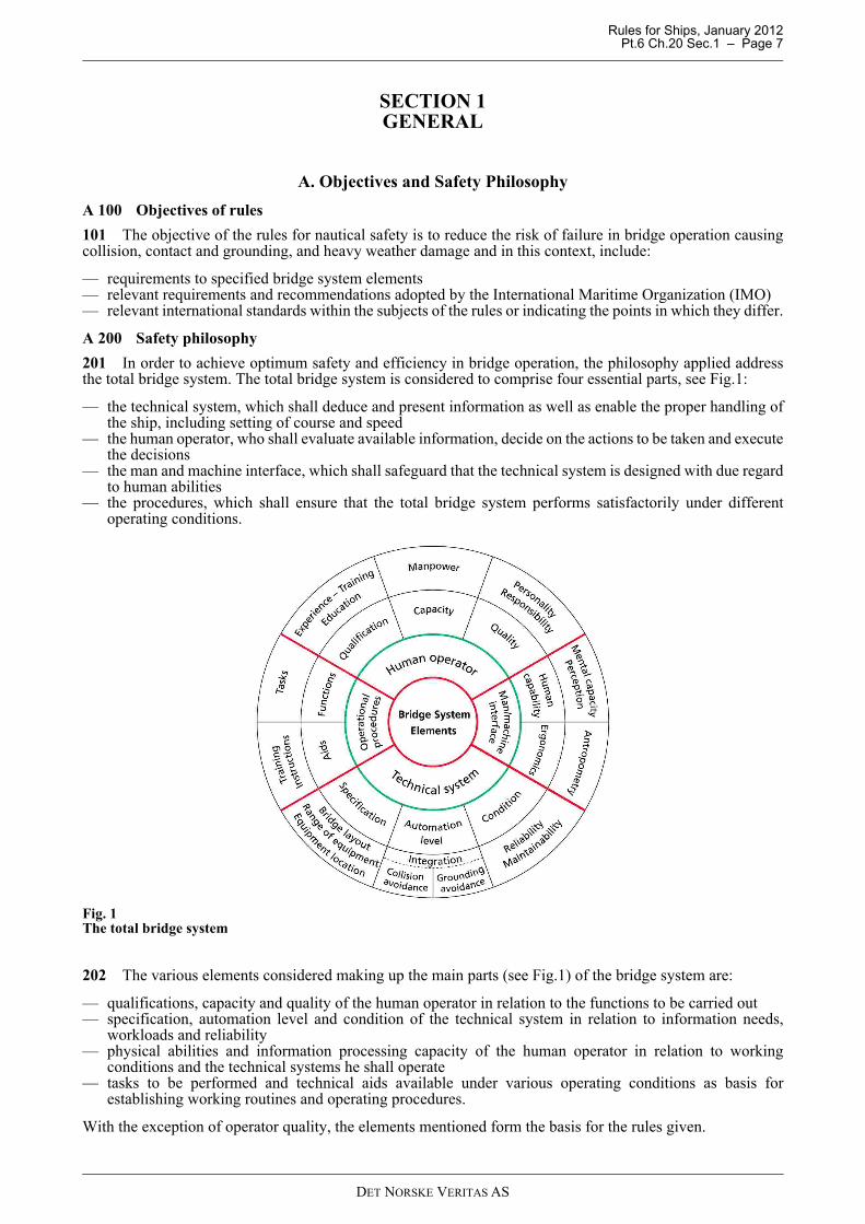
201 In order to achieve optimum safety and efficiency in bridge operation, the philosophy applied addressthe total bridge system. The total bridge system is considered to comprise four essential parts, see Fig.1:
— the technical system, which shall deduce and present information as well as enable the proper handling ofthe ship, including setting of course and speed
— the human operator, who shall evaluate available information, decide on the actions to be taken and executethe decisions
— the man and machine interface, which shall safeguard that the technical system is designed with due regardto human abilities
— the procedures, which shall ensure that the total bridge system performs satisfactorily under differentoperating conditions.
Fig. 1The total bridge system
202 The various elements considered making up the main parts (see Fig.1) of the bridge system are:
— qualifications, capacity and quality of the human operator in relation to the functions to be carried out— specification, automation level and condition of the technical system in relation to information needs,
workloads and reliability— physical abilities and information processing capacity of the human operator in relation to working
conditions and the technical systems he shall operate— tasks to be performed and technical aids available under various operating conditions as basis for
establishing working routines and operating procedures.
With the exception of operator quality, the elements mentioned form the basis for the rules given.
DET NORSKE VERITAS AS
Rules for Ships, January 2012 Pt.6 Ch.20 Sec.1 – Page 8
203 The rules take into consideration that the modes of operation and the manning of the bridge will vary inaccordance with the condition of internal technical systems and the availability of relevant external systems,and that operating conditions can be influenced by the waters to be navigated, traffic and weather conditions.
204 The rules aim at safeguarding that the officer of the watch, at his workstation, has full control of all thefunctions he is responsible for. Furthermore, that the bridge enables safe and efficient co-operation by twonavigators when required.
Guidance note:It should be noted that the manning of the navigational watch at all times shall be in accordance with the nationalregulations of the flag state and for the waters in which the ship is operating.
---e-n-d---of---G-u-i-d-a-n-c-e---n-o-t-e---
B. Scope of the Rules
B 100 Scope of rules
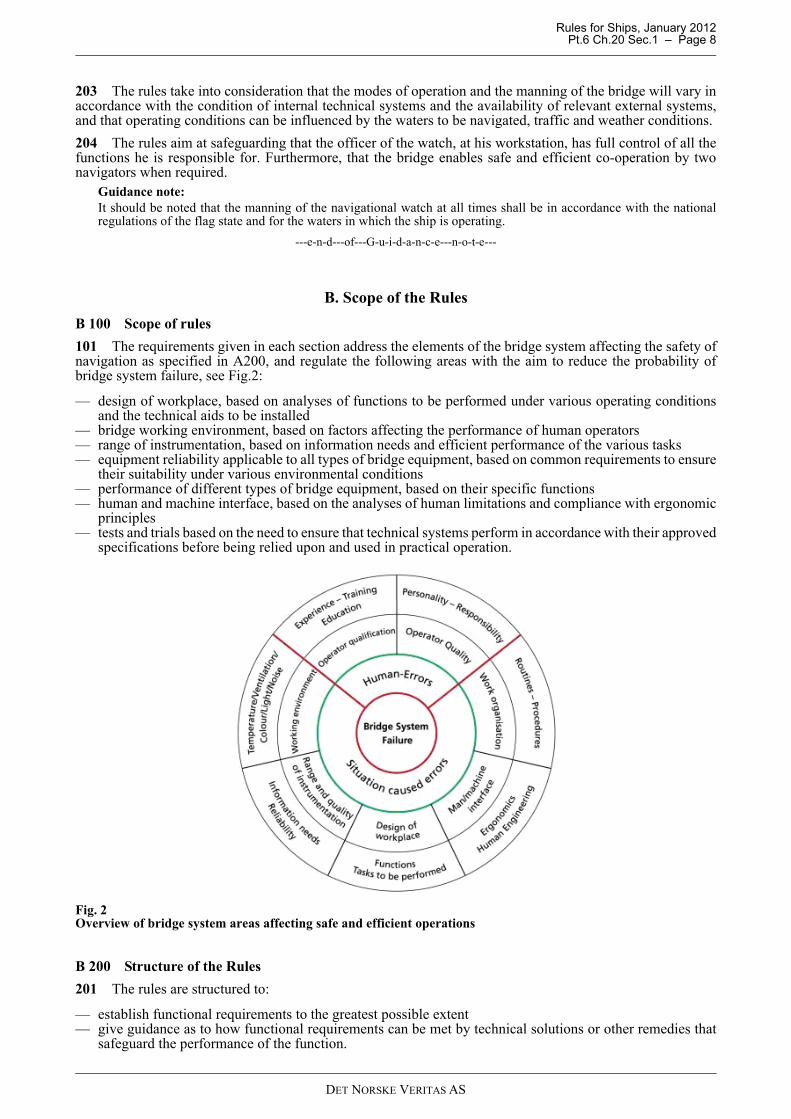
101 The requirements given in each section address the elements of the bridge system affecting the safety ofnavigation as specified in A200, and regulate the following areas with the aim to reduce the probability ofbridge system failure, see Fig.2:
— design of workplace, based on analyses of functions to be performed under various operating conditionsand the technical aids to be installed
— bridge working environment, based on factors affecting the performance of human operators— range of instrumentation, based on information needs and efficient performance of the various tasks— equipment reliability applicable to all types of bridge equipment, based on common requirements to ensure
their suitability under various environmental conditions— performance of different types of bridge equipment, based on their specific functions— human and machine interface, based on the analyses of human limitations and compliance with ergonomic
principles— tests and trials based on the need to ensure that technical systems perform in accordance with their approved
specifications before being relied upon and used in practical operation.
Fig. 2Overview of bridge system areas affecting safe and efficient operations
B 200 Structure of the Rules
201 The rules are structured to:
— establish functional requirements to the greatest possible extent— give guidance as to how functional requirements can be met by technical solutions or other remedies that
safeguard the performance of the function.
DET NORSKE VERITAS AS
Rules for Ships, January 2012 Pt.6 Ch.20 Sec.1 – Page 9
202 A Guidance note gives solutions that can be approved, but does not exclude the application of alternativesolutions provided the functional requirements are met.
203 Where rule requirement apply to vessels intended for specified operations such as AH, Towingoperations, AHTS, Oilrec. and FiFi the Society will base the approval on the information given in the classrequest. For vessels designed and prepared for operations that are not visible from class request, such asRescue, relevant Rules for such operations will be applied unless written confirmation received from yard andowner.
C. Definitions
C 100 Terms and abbreviations
101 Abnormal operating conditions: When internal technical system failures require operation of back-upsystems on the bridge or when they occur during an irregular operating condition, or when the officer of thewatch becomes unfit to perform his duties and has not yet been replaced by another qualified officer.
102 Additional functions: Additional functions requiring work tasks not directly related to primary bridgefunctions or offshore operations.
103 AH: Anchor handling.
104 AHTS: Anchor Handling, Tug Supply.
105 Back-up navigator: A navigational officer who has been designated by the ship’s master to be on call toassist or replace the officer of the watch when required.
106 Blind sector: An obstruction in a field of vision caused by window divisions, bridge structure or outsideconstruction with a clear sector on both sides.
107 BNWAS: Bridge Navigational Watch Alarm System.
108 Bridge system: The total system for the performance of bridge functions, comprising bridge personnel,technical systems, human and machine interface and procedures.
109 Bridge wing: The part of the bridge on each side of the wheelhouse, which extends to the ship’s side.
110 Bridge: The area from which the navigation and/or control of the ship are exercised, comprising thewheelhouse and the bridge wings.
111 Cargo Operations: Operations related to transferring or receiving general mixed cargo or liquid cargobetween ship and offshore installation, included control and monitoring of own ship and cargo gear. Ships onlydesigned for cargo operation is named Platform Supply Vessel.
112 Catwalk: Arrangement outside the wheelhouse allowing a person safe access to windows along thebulkhead(s).
113 CCTV: Closed Circuit Television.
114 Coastal waters: Waters that encompass navigation along a coast at a distance less than the equivalenceof 30 minutes of sailing with the relevant ship speed. The other side of the course line allows freedom of coursesetting in any direction for a distance equivalent to at least 30 minutes of sailing with the relevant speed.
115 Collision avoidance functions: Detection and plotting of other ships and moving objects; determinationand execution of course and speed deviations to avoid collision.
116 Commanding view: View without obstructions, which could interfere with the navigator’s ability toperform his main tasks, at least covering the field of vision required for safe performance of collision avoidancefunctions.
117 Conning information display: A screen-based information system that clearly presents information fromsensor inputs relevant to navigation and manoeuvring, as well as all corresponding and upcoming orders givenby an automatic navigation system to steering and propulsion systems if connected.
118 Conning station or position: Place in the wheelhouse with a commanding view providing the necessaryinformation for conning, and which is used by navigators when monitoring and directing the ship’s movements.
119 Control: Either effectuate actions or have orders effectuated.
120 Display: An observable illustration of an image, scene or data on a screen.
121 Distress situations: Loss of propulsion and/or steering, or when the ship is not seaworthy due to otherreasons (situation prior to abandon ship situation).
122 Docking: Manoeuvring the ship alongside a berth and controlling the mooring operations.
DET NORSKE VERITAS AS
Rules for Ships, January 2012 Pt.6 Ch.20 Sec.1 – Page 10
123 DP: Dynamic Positioning.
124 DPO: Dynamic Positioning system Operator.
125 Easily accessible: Within 5 m distance from working position.
126 Easily readable: Within the horizontal angle of 90 degrees to each side and vertical angle of 90 degreesbelow – to 60 degrees above the horizon from the normal line of sight for the operator.
127 Electronic chart display and information system (ECDIS): A navigation information system, which withadequate back-up arrangements can be accepted as complying with the up-to-date chart required by regulationV/20 of SOLAS Chapter V, and be accepted as meeting the chart carriage requirements of SOLAS Chapter V,as amended by Res. MSC.99(73), by displaying selected information from a system electronic nautical chart(SENC).
128 Electronic nautical chart (ENC): The database, standardised as to content, structure and format, issuedfor use with ECDIS on the authority of government authorised hydro graphic offices.
129 Emergency situations: When incidents seriously affect internal operating conditions of the ship and theability to maintain safe course and speed (fire, technical failure, structural damage).
130 Ergonomics: Application of the human factors implication in the analysis and design of the workplaceand equipment.
131 External safety operations: Assisting other in emergency situations.
132 Field of vision (FOV): Angular size of a scene that can be observed from a position on the ship’s bridge.
133 FiFi: Fire Fighting.
134 Hand-grasp area: For equipment/ control units continuous used. See Sec.3 E500 for guidance of area.
135 Helmsman: Person who steers the ship under way.
136 Irregular operating conditions: When external conditions cause excessive operator workloads.
137 Manoeuvring: Operation of thrusters, steering systems and propulsion machinery as required to movethe ship into predetermined directions, positions or tracks.
138 Monitoring: Act of constantly checking information from instrument displays and environment in orderto detect any irregularities.
139 Narrow waters: Waters that do not allow the freedom of course setting to any side of the course line fora distance equivalent to 30 minutes of sailing with the relevant ship speed.
140 Navigation: Planning of the ship’s route and determination of position and course of the ship, executionof course alterations and speed changes.
141 Navigational bridge: The area of the bridge where transit operation is performed.
142 Normal operating conditions: When all shipboard systems and equipment related to primary bridgefunctions operate within design limits, and weather conditions or traffic, do not cause excessive operatorworkloads.
143 Ocean areas: Waters that encompass navigation beyond the outer limits of coastal waters. Ocean areasdo not restrict the freedom of course setting in any direction for a distance equivalent to 30 minutes of sailingwith the relevant ship speed.
144 Officer of the watch (OOW): Person responsible for the safety of navigation and bridge operations untilrelieved by another qualified officer.
145 Oilrec: Oil recovery.
146 On Hand: For equipment/ control units used frequently or special important. See Sec.3 E500 forspecification of area.
147 Operational bridge: The area of the bridge where workstations for offshore operations are located.
148 Operational bridge functions: Functions related to ship handling in relation to the operation the vessel isengaged in. Such functions are:
— manoeuvring functions — deck equipment operation (for anchor handling, oil recovery and cargo transfer operations)— rescue operation— monitoring of internal safety systems— external and internal communication related to safety in bridge operation and distress situations— docking functions.
DET NORSKE VERITAS AS
Rules for Ships, January 2012 Pt.6 Ch.20 Sec.1 – Page 11
149 Popliteal height: The vertical distance from the footrest to the underside of the thigh.
150 Primary bridge functions: Functions related to determination, execution and maintenance of safe course,speed and position of the ship in relation to the waters, traffic and weather conditions. Such functions are:
— route planning functions— navigation functions— collision avoidance functions— manoeuvring functions— docking functions— monitoring of internal safety systems— external and internal communication related to safety in bridge operation and distress situations.
151 PSV: Platform Supply Vessel. A PSV is a vessel carrying out cargo operations.
152 Readable: Within a horizontal sector of 225° and vertical sector from 90° below to 60° above the horizonfrom the operators normal eye position.
153 Rescue: An operation where a defined vessel is, either bringing own personnel being in distress in thewater to safety, or is assisting an offshore platform, barge, production module/vessel or another ship in bringingtheir personnel being in distress in the water to safety.
154 Route monitoring: Continuous surveillance of the ship’s sailing (position and course) in relation to a pre-planned route and the waters.
155 Rudder angle: Rudder angle mean thruster angle when main propulsion is azimuth thrusters.
156 Route planning: Pre-determination of course lines, radius turns and speeds in relation to the waters to benavigated.
157 Safety operation: Handling of emergency and distress situations on board own ship or assisting othervessels and offshore installations in such situations.
158 SAR: Search And Rescue.
159 Screen: A device used for presenting visual information based on one or several displays.
160 SOLAS: The International Convention for the Safety of Life at Sea, 1974.
161 Superstructure: Decked structure, not including funnels, which is on or above the freeboard deck.
162 System electronic navigational chart (SENC): A database resulting from the transformation of the ENCby ECDIS for appropriate use, updates to the ENC by appropriate means and other data added by the mariner.
163 Towing operations: An operation including one or more offshore service vessels capable to assistoffshore platforms, barges and production modules/vessels in moving from one position to another, or inkeeping their defined position.
164 Wheelhouse: Enclosed area of the bridge.
165 Wheel-over-line: The line parallel to the new course line where the ship has to initiate a curved track toeliminate the effect of any offset with respect to the new course, taking into consideration the distance requiredfor the ship to build up the necessary turn rate.
166 Wheel-over-point: The point where the ship has to initiate a curved track, taking into consideration thedistance required for the ship to build up the necessary turn rate.
167 Within easy reach: For equipment/ control units used at the workstation. See Sec.3 E500 for specificationof area.
168 Within reach: The distance the operator can reach and use a control unit. See Sec.3 E500 for specificationof areas. For other workstations than workstations for offshore operations the area may be increased to:
— From a standing position this distance is regarded to be maximum 800 mm in forward direction and 1400mm sideways.
— From a seated position, at a distance of 350 mm from a console, this distance is regarded to be maximum1000 mm, and maximum 800 mm for frequently used equipment, which shall be within easy reach.
169 Workstation (WS): A work place at which one or several tasks constituting a particular activity arecarried out and which provides the information and equipment required for safe performance of the tasks.
170 Workstation for communication: A work place for operation and control of equipment for distress andsafety communication (GMDSS), and shipboard communication for ship operations.
DET NORSKE VERITAS AS
Rules for Ships, January 2012 Pt.6 Ch.20 Sec.1 – Page 12
171 Workstation for primary bridge functions: A workplace with commanding view used by navigators whencarrying out navigation, route monitoring, traffic surveillance and manoeuvring functions, and which enablesmonitoring of the safety state of the ship.
172 Workstation for safety operations: A workplace dedicated organisation and control of internalemergency and distress operations, and which provides easy access to information related to the safety state ofthe ship.
D. Class Notations
D 100 General
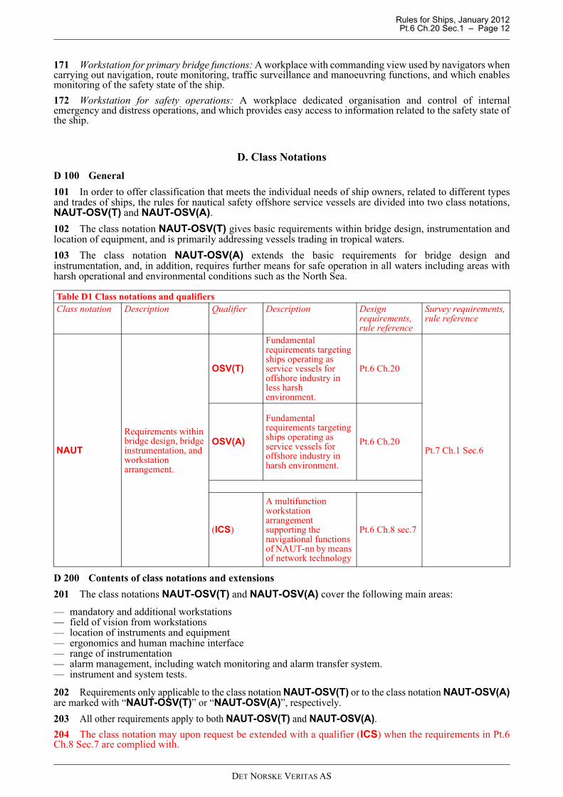
101 In order to offer classification that meets the individual needs of ship owners, related to different typesand trades of ships, the rules for nautical safety offshore service vessels are divided into two class notations,NAUT-OSV(T) and NAUT-OSV(A).
102 The class notation NAUT-OSV(T) gives basic requirements within bridge design, instrumentation andlocation of equipment, and is primarily addressing vessels trading in tropical waters.
103 The class notation NAUT-OSV(A) extends the basic requirements for bridge design andinstrumentation, and, in addition, requires further means for safe operation in all waters including areas withharsh operational and environmental conditions such as the North Sea.
D 200 Contents of class notations and extensions
201 The class notations NAUT-OSV(T) and NAUT-OSV(A) cover the following main areas:
— mandatory and additional workstations— field of vision from workstations— location of instruments and equipment— ergonomics and human machine interface— range of instrumentation— alarm management, including watch monitoring and alarm transfer system.— instrument and system tests.
202 Requirements only applicable to the class notation NAUT-OSV(T) or to the class notation NAUT-OSV(A)are marked with “NAUT-OSV(T)” or “NAUT-OSV(A)”, respectively.
203 All other requirements apply to both NAUT-OSV(T) and NAUT-OSV(A).
204 The class notation may upon request be extended with a qualifier (ICS) when the requirements in Pt.6Ch.8 Sec.7 are complied with.
Table D1 Class notations and qualifiersClass notation Description Qualifier Description Design
requirements, rule reference
Survey requirements, rule reference
NAUT
Requirements within bridge design, bridge instrumentation, and workstation arrangement.
OSV(T)
Fundamental requirements targeting ships operating as service vessels for offshore industry in less harsh environment.
Pt.6 Ch.20
Pt.7 Ch.1 Sec.6 OSV(A)
Fundamental requirements targeting ships operating as service vessels for offshore industry in harsh environment.
Pt.6 Ch.20
(ICS)
A multifunction workstation arrangement supporting the navigational functions of NAUT-nn by means of network technology
Pt.6 Ch.8 sec.7
DET NORSKE VERITAS AS
Rules for Ships, January 2012 Pt.6 Ch.20 Sec.1 – Page 13
D 300 Documentation of compliance
301 The class notations NAUT-OSV(T) and NAUT-OSV(A) imply that the ship is built and equipped incompliance with the relevant sections of this chapter.
D 400 Class assignment
401 The ship will be assigned class notation NAUT-OSV(T) or NAUT-OSV(A) when the relevantrequirements given in these rules are complied with.
E. Documentation for Approval
E 100 General
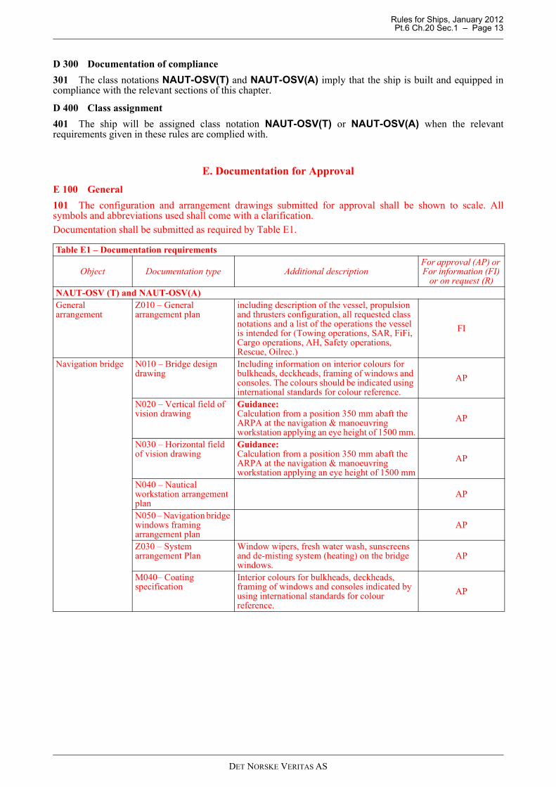
101 The configuration and arrangement drawings submitted for approval shall be shown to scale. Allsymbols and abbreviations used shall come with a clarification.Documentation shall be submitted as required by Table E1.
Table E1 – Documentation requirements
Object Documentation type Additional descriptionFor approval (AP) or For information (FI)
or on request (R)NAUT-OSV (T) and NAUT-OSV(A)General arrangement
Z010 – General arrangement plan
including description of the vessel, propulsion and thrusters configuration, all requested class notations and a list of the operations the vessel is intended for (Towing operations, SAR, FiFi, Cargo operations, AH, Safety operations, Rescue, Oilrec.)
FI
Navigation bridge N010 – Bridge design drawing
Including information on interior colours for bulkheads, deckheads, framing of windows and consoles. The colours should be indicated using international standards for colour reference.
AP
N020 – Vertical field of vision drawing
Guidance:Calculation from a position 350 mm abaft the ARPA at the navigation & manoeuvring workstation applying an eye height of 1500 mm.
AP
N030 – Horizontal field of vision drawing
Guidance:Calculation from a position 350 mm abaft the ARPA at the navigation & manoeuvring workstation applying an eye height of 1500 mm
AP
N040 – Nautical workstation arrangement plan
AP
N050 – Navigation bridge windows framing arrangement plan
AP
Z030 – System arrangement Plan
Window wipers, fresh water wash, sunscreens and de-misting system (heating) on the bridge windows.
AP
M040– Coating specification
Interior colours for bulkheads, deckheads, framing of windows and consoles indicated by using international standards for colour reference.
AP
DET NORSKE VERITAS AS
Rules for Ships, January 2012 Pt.6 Ch.20 Sec.1 – Page 14
102 For general requirements to documentation, see Pt.0 Ch.3 Sec.1.
103 For a full definition of the documentation types, see Pt.0 Ch.3 Sec.2.
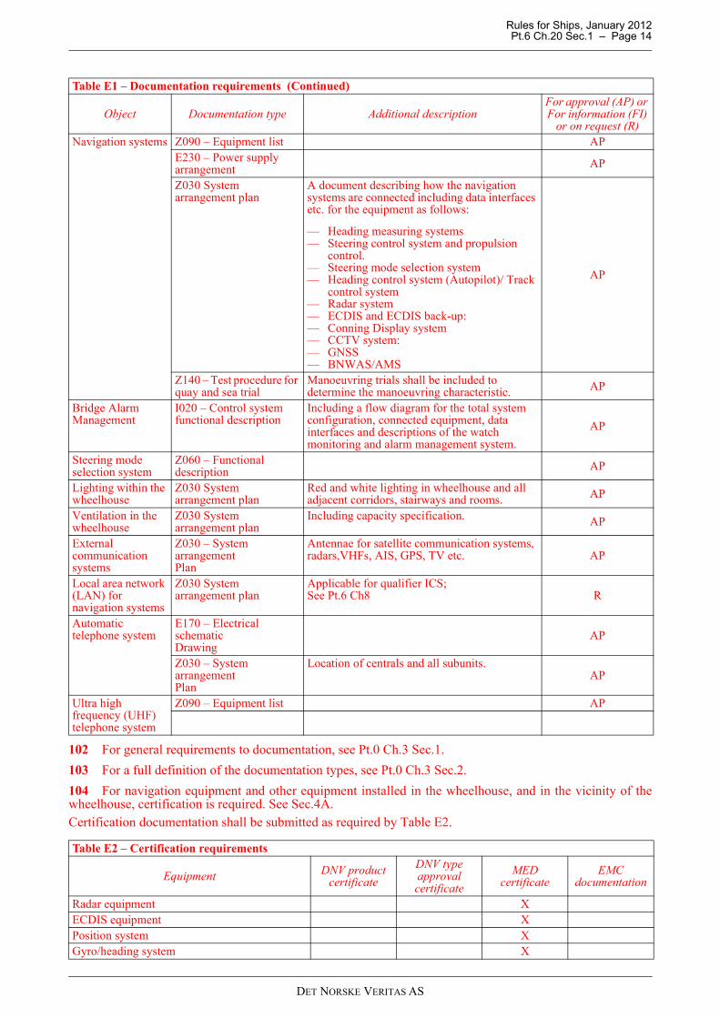
104 For navigation equipment and other equipment installed in the wheelhouse, and in the vicinity of thewheelhouse, certification is required. See Sec.4A.Certification documentation shall be submitted as required by Table E2.
Navigation systems Z090 – Equipment list APE230 – Power supply arrangement AP
Z030 System arrangement plan
A document describing how the navigation systems are connected including data interfaces etc. for the equipment as follows:
— Heading measuring systems— Steering control system and propulsion
control.— Steering mode selection system— Heading control system (Autopilot)/ Track
control system— Radar system— ECDIS and ECDIS back-up:— Conning Display system— CCTV system: — GNSS— BNWAS/AMS
AP
Z140 – Test procedure for quay and sea trial
Manoeuvring trials shall be included to determine the manoeuvring characteristic. AP
Bridge AlarmManagement
I020 – Control systemfunctional description
Including a flow diagram for the total systemconfiguration, connected equipment, data interfaces and descriptions of the watch monitoring and alarm management system.
AP
Steering mode selection system
Z060 – Functional description AP
Lighting within the wheelhouse
Z030 System arrangement plan
Red and white lighting in wheelhouse and all adjacent corridors, stairways and rooms. AP
Ventilation in the wheelhouse
Z030 System arrangement plan
Including capacity specification. AP
External communicationsystems
Z030 – System arrangementPlan
Antennae for satellite communication systems, radars,VHFs, AIS, GPS, TV etc. AP
Local area network (LAN) for navigation systems
Z030 System arrangement plan
Applicable for qualifier ICS;See Pt.6 Ch8 R
Automatic telephone system
E170 – Electrical schematicDrawing
AP
Z030 – System arrangementPlan
Location of centrals and all subunits.AP
Ultra highfrequency (UHF)telephone system
Z090 – Equipment list AP
Table E2 – Certification requirements
Equipment DNV product certificate
DNV type approval certificate
MEDcertificate
EMC documentation
Radar equipment XECDIS equipment XPosition system XGyro/heading system X
Table E1 – Documentation requirements (Continued)
Object Documentation type Additional descriptionFor approval (AP) or For information (FI)
or on request (R)
DET NORSKE VERITAS AS
Rules for Ships, January 2012 Pt.6 Ch.20 Sec.1 – Page 15
F. Functional Tests
F 100 The following tests shall be carried out
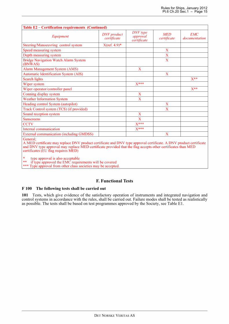
101 Tests, which give evidence of the satisfactory operation of instruments and integrated navigation andcontrol systems in accordance with the rules, shall be carried out. Failure modes shall be tested as realisticallyas possible. The tests shall be based on test programmes approved by the Society, see Table E1.
Steering/Manoeuvring control system X(ref. 4.9)*Speed measuring system XDepth measuring system XBridge Navigation Watch Alarm System (BNWAS)
X
Alarm Management System (AMS) XAutomatic Identification System (AIS) XSearch lights X**Wiper system X***Wiper operator/controller panel X**Conning display system XWeather Information System XHeading control System (autopilot) XTrack Control system (TCS) (if provided) XSound reception system XSunscreens XCCTV X***Internal communication X***External communication (including GMDSS) XGeneral;A MED certificate may replace DNV product certificate and DNV type approval certificate. A DNV product certificate and DNV type approval may replace MED certificate provided that the flag accepts other certificates than MED certificates (EU flag requires MED)
* type approval is also acceptable** if type approved the EMC requirements will be covered*** Type approval from other class societies may be accepted.
Table E2 – Certification requirements (Continued)
Equipment DNV product certificate
DNV type approval certificate
MEDcertificate
EMC documentation
DET NORSKE VERITAS AS
Rules for Ships, January 2012 Pt.6 Ch.20 Sec.2 – Page 16
SECTION 2 BRIDGE DESIGN AND CONFIGURATION
A. General
A 100 Bridge operations
101 Based on the variety of missions Offshore Service Vessels (OSV) carry out, different operations will beperformed from the navigational and the operational bridge. Some operations may be performed from both theoperational and the navigational bridge depending on the character of the operation.
Guidance note:The basis for these rules is the traditional offshore service vessel with the deck aft of the vessel superstructure andrule wording reflect this. Other vessel designs are possible and will be considered to meet these rules when thefunctional requirements are meet.
---e-n-d---of---G-u-i-d-a-n-c-e---n-o-t-e---
102 Performance of the following operations shall, as applicable, be facilitated from the bridge:
— transit— docking operations— towing operations— search/rescue operations— fire fighting (FiFi).— seismic operations
103 Performance of the following operations shall, as applicable, be facilitated from the bridge:
— docking operations— cargo operations— anchor handling— towing operations— safety operations— search/rescue operations— oil recovery (Oilrec)— fire fighting (FiFi) well intervention operations.— cable/pipe laying operations— windmill installation— subsea operations
B. Workstations
B 100 Navigational bridge
101 The design and location of the workstations shall enable the ship to be navigated and manoeuvred safelyand efficiently by one navigator in ocean areas and coastal waters under normal operating conditions, as wellas by two navigators in close co-operation when the workload exceeds the capacity of one person, and whenunder pilotage.
102 The following workstations for primary bridge functions shall be arranged at the navigational bridge asa minimum to achieve safe and efficient operation under all conditions:
— workstations for navigating & manoeuvring— workstations for monitoring workstation for route planning— workstation for docking/search/rescue operations
Guidance note:Workstation for route planning may be combined with workstation for monitoring or workstations for navigating &manoeuvring.Workstation for docking operations may be part of workstation for rescue or workstations for navigating &manoeuvring and/ or workstation for ship handling.
---e-n-d---of---G-u-i-d-a-n-c-e---n-o-t-e---
B 200 Operational bridge
201 In addition to normal bridge functions carried out on a conventional ship in connection with watch duty
DET NORSKE VERITAS AS
Rules for Ships, January 2012 Pt.6 Ch.20 Sec.2 – Page 17
on the bridge, arrangement for several other functions will have to be taken into consideration on an offshoreservice vessel serving in multi-roles. These functions are normally carried out from the operational part of thebridge on an offshore service vessel. Separate workstations are required in order to facilitate these functions.
202 The design and location of the workstations shall enable safe and efficient positioning/ manoeuvring of theship and safe and efficient operation/ monitoring of all deck equipment needed for carrying out the differentoperations relevant for the ship.
203 The configuration of the workstations shall facilitate performance by one operator under normaloperating conditions, as well as by two operators in close co-operation when the workload exceeds the capacityof one person.
204 To allow operations either by one operator alone or by two operators in close co-operation, the followingworkstations are required at the operational bridge:
— workstation for ship handling— workstation for aft support.
B 300 Additional workstations
301 When functions additional to the primary functions and functions related to cargo operation shall beperformed, workstations shall be arranged for these.Such workstations may include:
— workstation for docking/rescue operations— workstation for fire fighting— workstation for safety monitoring and emergency operations— workstation for communication.
Guidance note:Workstation for safety monitoring and emergency operations may be combined with workstation for communication.Workstation for FiFi may be mobile or located in several different places.
---e-n-d---of---G-u-i-d-a-n-c-e---n-o-t-e---
B 400 Required workstations for different types of vessels
401 Based upon the operations the vessel is designed to perform, according to Sec.1 E102, the followingworkstations shall be provided:
Guidance note:Requirement for workstations Fire Fighting and Rescue will be based upon the information required in Sec.1 tableE1with respect to intended operation.
---e-n-d---of---G-u-i-d-a-n-c-e---n-o-t-e---
Table B1 WorkstationsWorkstation for: All Rescue FiFi Seismic
vesselsNavigating & manoeuvring XMonitoring XRoute planning X*Docking X* X**Ship handling X X**Aft support X X**Search/Rescue X X**Fire fighting X X**Communication XSafety X* The workstations for route planning and docking may be combined with other workstations.** Workstations may not be applicable for seismic vessels
DET NORSKE VERITAS AS
Rules for Ships, January 2012 Pt.6 Ch.20 Sec.2 – Page 18
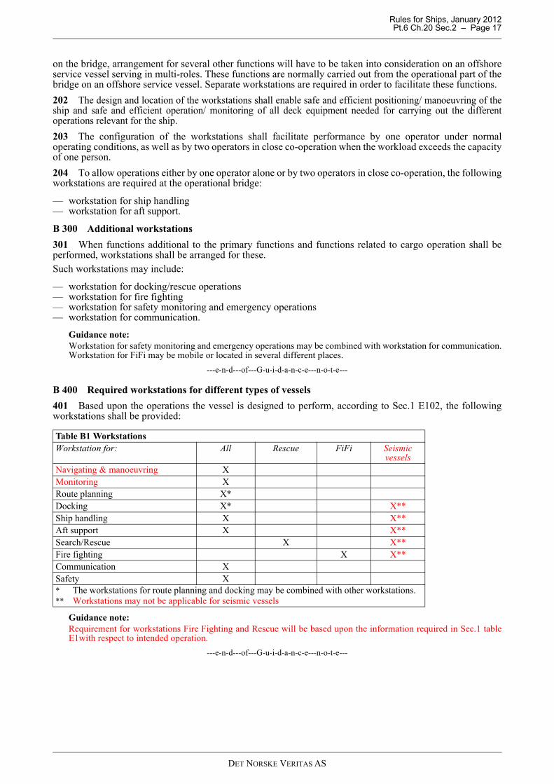
Fig. 1Example of bridge configuration and arrangement of workstations
C. Visibility
C 100 General
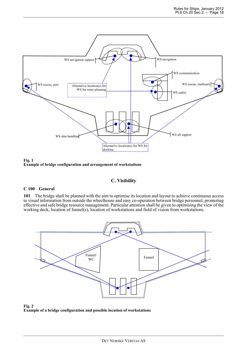
101 The bridge shall be planned with the aim to optimise its location and layout to achieve continuous accessto visual information from outside the wheelhouse and easy co-operation between bridge personnel, promotingeffective and safe bridge resource management. Particular attention shall be given to optimising the view of theworking deck, location of funnel(s), location of workstations and field of vision from workstations.
Fig. 2Example of a bridge configuration and possible location of workstations
WS rescue, port WS rescue, starboard
WS aft support
WS navigation support WS navigation
WS safety
WS communication
Alternative location(s) for WS for docking
WS ship handling
Alternative location(s) for WS for route planning
Funnel
Funnel/ WC
DET NORSKE VERITAS AS
Rules for Ships, January 2012 Pt.6 Ch.20 Sec.2 – Page 19
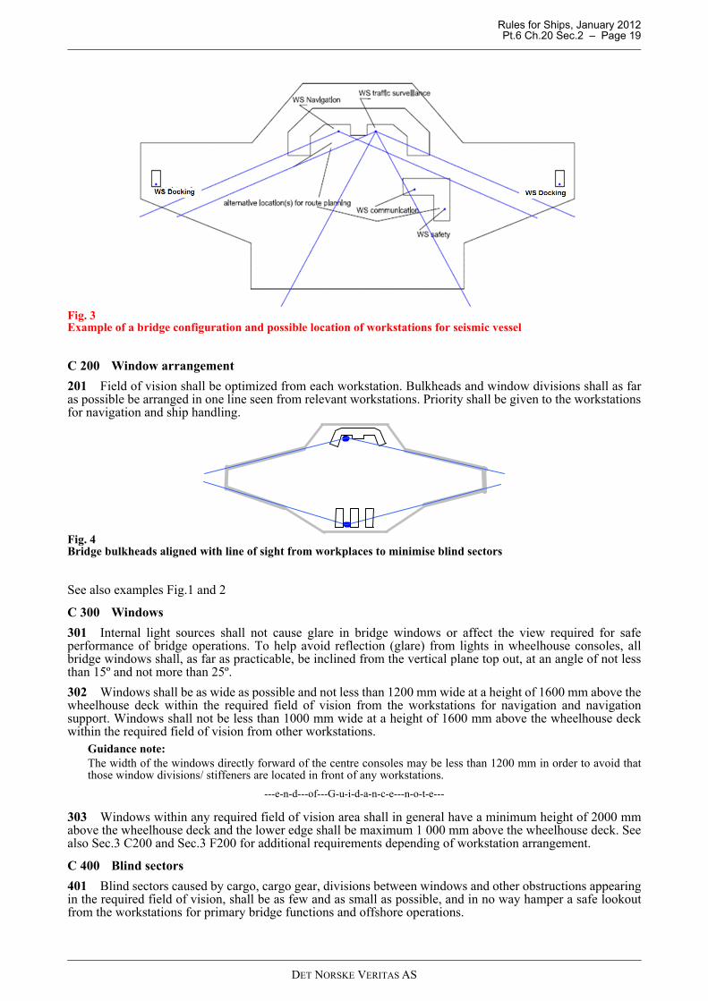
Fig. 3Example of a bridge configuration and possible location of workstations for seismic vessel
C 200 Window arrangement
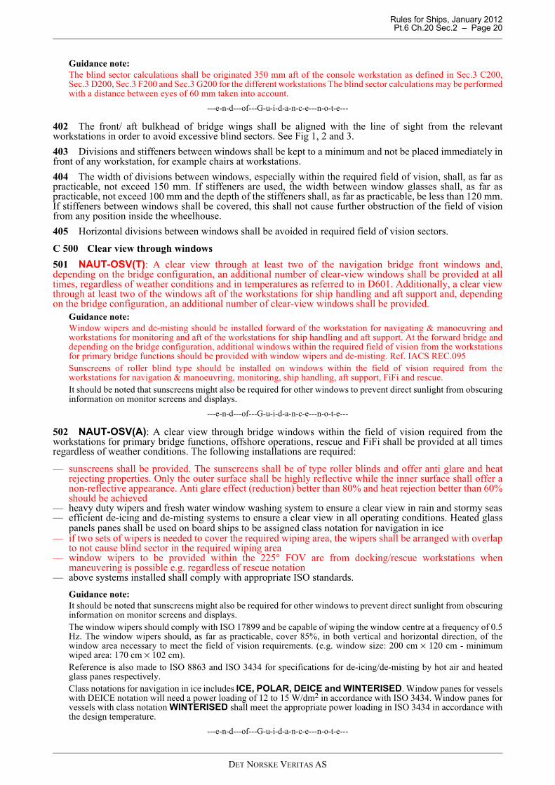
201 Field of vision shall be optimized from each workstation. Bulkheads and window divisions shall as faras possible be arranged in one line seen from relevant workstations. Priority shall be given to the workstationsfor navigation and ship handling.
Fig. 4Bridge bulkheads aligned with line of sight from workplaces to minimise blind sectors
See also examples Fig.1 and 2
C 300 Windows
301 Internal light sources shall not cause glare in bridge windows or affect the view required for safeperformance of bridge operations. To help avoid reflection (glare) from lights in wheelhouse consoles, allbridge windows shall, as far as practicable, be inclined from the vertical plane top out, at an angle of not lessthan 15º and not more than 25º.
302 Windows shall be as wide as possible and not less than 1200 mm wide at a height of 1600 mm above thewheelhouse deck within the required field of vision from the workstations for navigation and navigationsupport. Windows shall not be less than 1000 mm wide at a height of 1600 mm above the wheelhouse deckwithin the required field of vision from other workstations.
Guidance note:The width of the windows directly forward of the centre consoles may be less than 1200 mm in order to avoid thatthose window divisions/ stiffeners are located in front of any workstations.
---e-n-d---of---G-u-i-d-a-n-c-e---n-o-t-e---
303 Windows within any required field of vision area shall in general have a minimum height of 2000 mmabove the wheelhouse deck and the lower edge shall be maximum 1 000 mm above the wheelhouse deck. Seealso Sec.3 C200 and Sec.3 F200 for additional requirements depending of workstation arrangement.
C 400 Blind sectors
401 Blind sectors caused by cargo, cargo gear, divisions between windows and other obstructions appearingin the required field of vision, shall be as few and as small as possible, and in no way hamper a safe lookoutfrom the workstations for primary bridge functions and offshore operations.
DET NORSKE VERITAS AS
Rules for Ships, January 2012 Pt.6 Ch.20 Sec.2 – Page 20
Guidance note:The blind sector calculations shall be originated 350 mm aft of the console workstation as defined in Sec.3 C200,Sec.3 D200, Sec.3 F200 and Sec.3 G200 for the different workstations The blind sector calculations may be performedwith a distance between eyes of 60 mm taken into account.
---e-n-d---of---G-u-i-d-a-n-c-e---n-o-t-e---
402 The front/ aft bulkhead of bridge wings shall be aligned with the line of sight from the relevantworkstations in order to avoid excessive blind sectors. See Fig 1, 2 and 3.
403 Divisions and stiffeners between windows shall be kept to a minimum and not be placed immediately infront of any workstation, for example chairs at workstations.
404 The width of divisions between windows, especially within the required field of vision, shall, as far aspracticable, not exceed 150 mm. If stiffeners are used, the width between window glasses shall, as far aspracticable, not exceed 100 mm and the depth of the stiffeners shall, as far as practicable, be less than 120 mm.If stiffeners between windows shall be covered, this shall not cause further obstruction of the field of visionfrom any position inside the wheelhouse.
405 Horizontal divisions between windows shall be avoided in required field of vision sectors.
C 500 Clear view through windows
501 NAUT-OSV(T): A clear view through at least two of the navigation bridge front windows and,depending on the bridge configuration, an additional number of clear-view windows shall be provided at alltimes, regardless of weather conditions and in temperatures as referred to in D601. Additionally, a clear viewthrough at least two of the windows aft of the workstations for ship handling and aft support and, dependingon the bridge configuration, an additional number of clear-view windows shall be provided.
Guidance note:Window wipers and de-misting should be installed forward of the workstation for navigating & manoeuvring andworkstations for monitoring and aft of the workstations for ship handling and aft support. At the forward bridge anddepending on the bridge configuration, additional windows within the required field of vision from the workstationsfor primary bridge functions should be provided with window wipers and de-misting. Ref. IACS REC.095Sunscreens of roller blind type should be installed on windows within the field of vision required from theworkstations for navigation & manoeuvring, monitoring, ship handling, aft support, FiFi and rescue. It should be noted that sunscreens might also be required for other windows to prevent direct sunlight from obscuringinformation on monitor screens and displays.
---e-n-d---of---G-u-i-d-a-n-c-e---n-o-t-e---
502 NAUT-OSV(A): A clear view through bridge windows within the field of vision required from theworkstations for primary bridge functions, offshore operations, rescue and FiFi shall be provided at all timesregardless of weather conditions. The following installations are required:
— sunscreens shall be provided. The sunscreens shall be of type roller blinds and offer anti glare and heatrejecting properties. Only the outer surface shall be highly reflective while the inner surface shall offer anon-reflective appearance. Anti glare effect (reduction) better than 80% and heat rejection better than 60%should be achieved
— heavy duty wipers and fresh water window washing system to ensure a clear view in rain and stormy seas— efficient de-icing and de-misting systems to ensure a clear view in all operating conditions. Heated glass
panels panes shall be used on board ships to be assigned class notation for navigation in ice— if two sets of wipers is needed to cover the required wiping area, the wipers shall be arranged with overlap
to not cause blind sector in the required wiping area— window wipers to be provided within the 225° FOV arc from docking/rescue workstations when
maneuvering is possible e.g. regardless of rescue notation — above systems installed shall comply with appropriate ISO standards.
Guidance note:It should be noted that sunscreens might also be required for other windows to prevent direct sunlight from obscuringinformation on monitor screens and displays.The window wipers should comply with ISO 17899 and be capable of wiping the window centre at a frequency of 0.5Hz. The window wipers should, as far as practicable, cover 85%, in both vertical and horizontal direction, of thewindow area necessary to meet the field of vision requirements. (e.g. window size: 200 cm × 120 cm - minimumwiped area: 170 cm × 102 cm). Reference is also made to ISO 8863 and ISO 3434 for specifications for de-icing/de-misting by hot air and heatedglass panes respectively.Class notations for navigation in ice includes ICE, POLAR, DEICE and WINTERISED. Window panes for vesselswith DEICE notation will need a power loading of 12 to 15 W/dm2 in accordance with ISO 3434. Window panes forvessels with class notation WINTERISED shall meet the appropriate power loading in ISO 3434 in accordance withthe design temperature.
---e-n-d---of---G-u-i-d-a-n-c-e---n-o-t-e---
DET NORSKE VERITAS AS
Rules for Ships, January 2012 Pt.6 Ch.20 Sec.2 – Page 21
503 The glass panes used shall not give any blurred effect to the line of sight. The linearity of the viewthrough the windows shall not be adversely affected by the design of window.
Guidance note:Taking bearings through the glass pane shall not result in more than 0.5° distortion seen within angles of +/- 60°.
---e-n-d---of---G-u-i-d-a-n-c-e---n-o-t-e---
504 A fixed catwalk or similar arrangement with means to prevent an accidental fall shall be fitted at thewindows without adjacent deck to enable cleaning of windows and repair work in the event of failure of thecleaning systems.
D. Working Environment
D 100 General
101 Throughout the various design stages of the ship, care shall be taken to achieve an optimal workingenvironment for bridge personnel.
102 Toilet facilities shall be provided on or adjacent to the bridge.
103 Refreshment facilities and other amenities provided for the bridge personnel shall include means for preventingdamage to bridge equipment and injury to personnel resulting from the use of such facilities and amenities.
D 200 Deckhead height
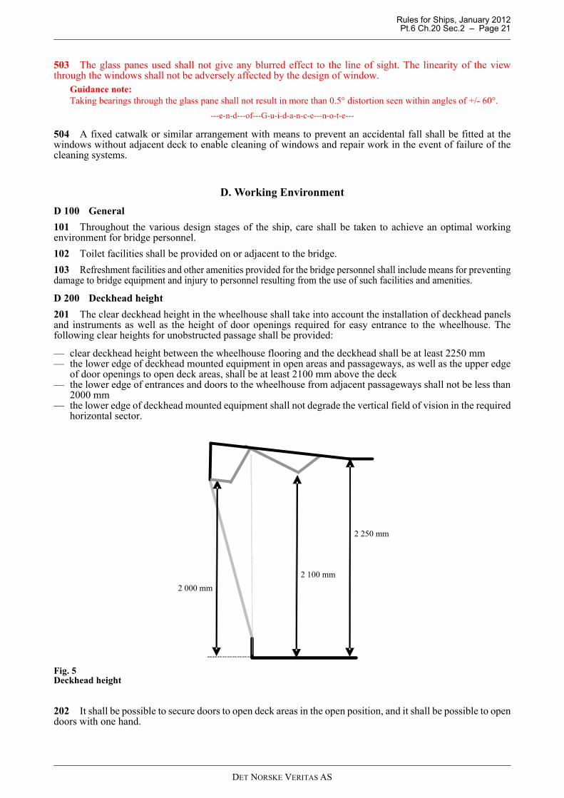
201 The clear deckhead height in the wheelhouse shall take into account the installation of deckhead panelsand instruments as well as the height of door openings required for easy entrance to the wheelhouse. Thefollowing clear heights for unobstructed passage shall be provided:
— clear deckhead height between the wheelhouse flooring and the deckhead shall be at least 2250 mm— the lower edge of deckhead mounted equipment in open areas and passageways, as well as the upper edge
of door openings to open deck areas, shall be at least 2100 mm above the deck— the lower edge of entrances and doors to the wheelhouse from adjacent passageways shall not be less than
2000 mm— the lower edge of deckhead mounted equipment shall not degrade the vertical field of vision in the required
horizontal sector.
Fig. 5Deckhead height
202 It shall be possible to secure doors to open deck areas in the open position, and it shall be possible to opendoors with one hand.
2 000 mm
2 100 mm
2 250 mm
DET NORSKE VERITAS AS
Rules for Ships, January 2012 Pt.6 Ch.20 Sec.2 – Page 22
203 Ships with fully enclosed bridge wings shall have at least one door providing direct access to the adjacentarea outside the wheelhouse.
D 300 Passageways
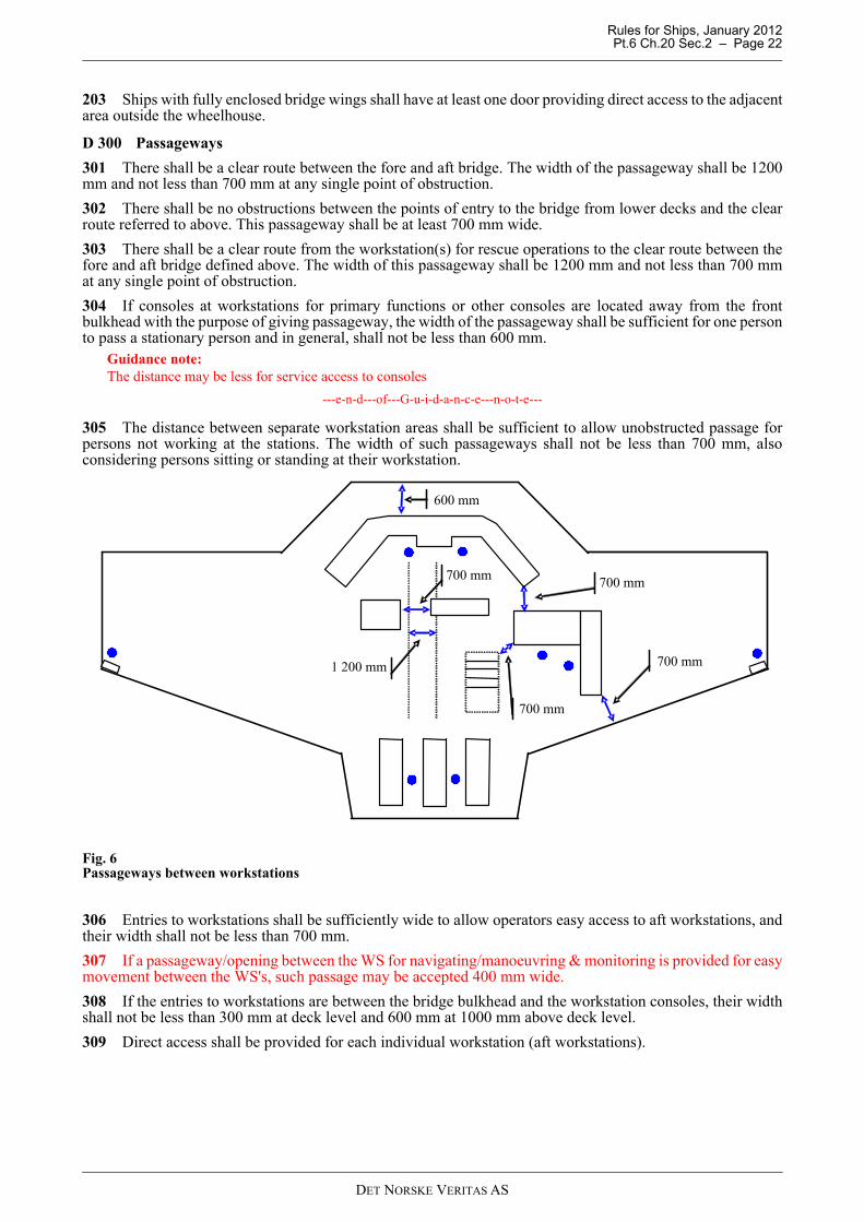
301 There shall be a clear route between the fore and aft bridge. The width of the passageway shall be 1200mm and not less than 700 mm at any single point of obstruction.
302 There shall be no obstructions between the points of entry to the bridge from lower decks and the clearroute referred to above. This passageway shall be at least 700 mm wide.
303 There shall be a clear route from the workstation(s) for rescue operations to the clear route between thefore and aft bridge defined above. The width of this passageway shall be 1200 mm and not less than 700 mmat any single point of obstruction.
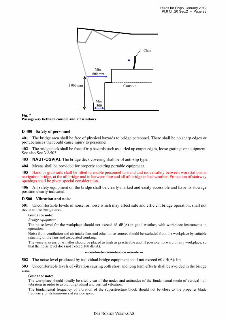
304 If consoles at workstations for primary functions or other consoles are located away from the frontbulkhead with the purpose of giving passageway, the width of the passageway shall be sufficient for one personto pass a stationary person and in general, shall not be less than 600 mm.
Guidance note:The distance may be less for service access to consoles
---e-n-d---of---G-u-i-d-a-n-c-e---n-o-t-e---
305 The distance between separate workstation areas shall be sufficient to allow unobstructed passage forpersons not working at the stations. The width of such passageways shall not be less than 700 mm, alsoconsidering persons sitting or standing at their workstation.
Fig. 6Passageways between workstations
306 Entries to workstations shall be sufficiently wide to allow operators easy access to aft workstations, andtheir width shall not be less than 700 mm.
307 If a passageway/opening between the WS for navigating/manoeuvring & monitoring is provided for easymovement between the WS's, such passage may be accepted 400 mm wide.
308 If the entries to workstations are between the bridge bulkhead and the workstation consoles, their widthshall not be less than 300 mm at deck level and 600 mm at 1000 mm above deck level.
309 Direct access shall be provided for each individual workstation (aft workstations).
700 mm
700 mm
700 mm
700 mm
600 mm
1 200 mm
DET NORSKE VERITAS AS
Rules for Ships, January 2012 Pt.6 Ch.20 Sec.2 – Page 23
Fig. 7Passageway between console and aft windows
D 400 Safety of personnel
401 The bridge area shall be free of physical hazards to bridge personnel. There shall be no sharp edges orprotuberances that could cause injury to personnel.
402 The bridge deck shall be free of trip hazards such as curled up carpet edges, loose gratings or equipment.See also Sec.3 A503.
403 NAUT-OSV(A): The bridge deck covering shall be of anti-slip type.
404 Means shall be provided for properly securing portable equipment.
405 Hand or grab rails shall be fitted to enable personnel to stand and move safely between workstations atnavigation bridge, at the aft bridge and in between fore and aft aft bridge in bad weather. Protection of stairwayopenings shall be given special consideration.
406 All safety equipment on the bridge shall be clearly marked and easily accessible and have its stowageposition clearly indicated.
D 500 Vibration and noise
501 Uncomfortable levels of noise, or noise which may affect safe and efficient bridge operation, shall notoccur in the bridge area.
Guidance note:Bridge equipmentThe noise level for the workplace should not exceed 65 dB(A) in good weather, with workplace instruments inoperation.Noise from ventilation and air intake fans and other noise sources should be excluded from the workplace by suitablesituating of the fans and associated trunking.The vessel's sirens or whistles should be placed as high as practicable and, if possible, forward of any workplace, sothat the noise level does not exceed 100 dB(A).
---e-n-d---of---G-u-i-d-a-n-c-e---n-o-t-e---
502 The noise level produced by individual bridge equipment shall not exceed 60 dB(A)/1m.
503 Uncomfortable levels of vibration causing both short and long term effects shall be avoided in the bridgearea.
Guidance note:The workplace should ideally be sited clear of the nodes and antinodes of the fundamental mode of vertical hullvibration in order to avoid longitudinal and vertical vibration.The fundamental frequency of vibration of the superstructure block should not be close to the propeller bladefrequency or its harmonics at service speed.
800
1 000 mm
Min.600 mm
Chair
Console
Min.300
DET NORSKE VERITAS AS
Rules for Ships, January 2012 Pt.6 Ch.20 Sec.2 – Page 24
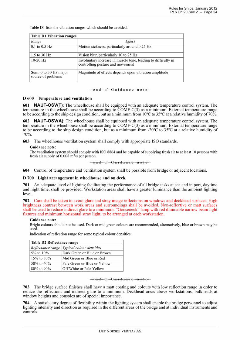
Table D1 lists the vibration ranges which should be avoided.
---e-n-d---of---G-u-i-d-a-n-c-e---n-o-t-e---
D 600 Temperature and ventilation
601 NAUT-OSV(T): The wheelhouse shall be equipped with an adequate temperature control system. Thetemperature in the wheelhouse shall be according to COMF-C(3) as a minimum. External temperature rangeto be according to the ship design condition, but as a minimum from 10ºC to 35ºC at a relative humidity of 70%.
602 NAUT-OSV(A): The wheelhouse shall be equipped with an adequate temperature control system. Thetemperature in the wheelhouse shall be according to COMF-C(3) as a minimum. External temperature rangeto be according to the ship design condition, but as a minimum from -20ºC to 35ºC at a relative humidity of70%.
603 The wheelhouse ventilation system shall comply with appropriate ISO standards.Guidance note:The ventilation system should comply with ISO 8864 and be capable of supplying fresh air to at least 10 persons withfresh air supply of 0.008 m3/s per person.
---e-n-d---of---G-u-i-d-a-n-c-e---n-o-t-e---
604 Control of temperature and ventilation system shall be possible from bridge or adjacent locations.
D 700 Light arrangement in wheelhouse and on deck
701 An adequate level of lighting facilitating the performance of all bridge tasks at sea and in port, daytimeand night time, shall be provided. Workstation areas shall have a greater luminance than the ambient lightinglevel.
702 Care shall be taken to avoid glare and stray image reflections on windows and deckhead surfaces. Highbrightness contrast between work areas and surroundings shall be avoided. Non-reflective or matt surfacesshall be used to reduce indirect glare to a minimum. “Gooseneck” lamp with red dimmable narrow beam lightfixtures and minimum horizontal stray light, to be arranged at each workstation.
Guidance note:Bright colours should not be used. Dark or mid green colours are recommended, alternatively, blue or brown may beused.Indication of reflection range for some typical colour densities:
---e-n-d---of---G-u-i-d-a-n-c-e---n-o-t-e---
703 The bridge surface finishes shall have a matt coating and colours with low reflection range in order toreduce the reflections and indirect glare to a minimum. Deckhead areas above workstations, bulkheads atwindow heights and consoles are of special importance.
704 A satisfactory degree of flexibility within the lighting system shall enable the bridge personnel to adjustlighting intensity and direction as required in the different areas of the bridge and at individual instruments andcontrols.
Table D1 Vibration rangesRange Effect0.1 to 0.5 Hz Motion sickness, particularly around 0.25 Hz
1.5 to 30 Hz Vision blur, particularly 10 to 25 Hz10-20 Hz Involuntary increase in muscle tone, leading to difficulty in
controlling posture and movement
Sum: 0 to 30 Hz major source of problems
Magnitude of effects depends upon vibration amplitude
Table D2 Reflectance rangeReflectance range Typical colour densities5% to 10% Dark Green or Blue or Brown15% to 30% Mid Green or Blue or Red50% to 60% Pale Green or Blue or Yellow80% to 90% Off White or Pale Yellow
DET NORSKE VERITAS AS
Rules for Ships, January 2012 Pt.6 Ch.20 Sec.2 – Page 25
705 During hours of darkness, it shall be possible to discern control devices and read displayed information.
706 Adequate lighting shall be provided in order to allow monitoring of deck both daytime and night time.
707 It shall be avoided that glaring lights from deck lights and searchlights are dazzling the operator at theworkstations.
708 Toilet shall be provided with red light for use during night and white light for day time. Alternatively canwhite dimmable light be used provided that dimming switch is located outside of toilet.
DET NORSKE VERITAS AS
Rules for Ships, January 2012 Pt.6 Ch.20 Sec.3 – Page 26
SECTION 3 WORKSTATION ARRANGEMENT
A. Requirements for the Various Workstations
A 100 General
101 This section gives the functional requirements for the various workstations and defines the tasks to becarried out at each workstation. Minimum field of vision, required equipment and information necessary forsafe performance of the tasks are given for each workstation as relevant.
A 200 General workstation requirements
201 Workstations and consoles shall be arranged and ergonomically designed to optimise the user’s workingconditions and to minimise excessive or unnecessary work.
202 A functional workstation designed in accordance with the established overall operational and ergonomicrequirements for safe operation must provide:
— a sufficient area for performance of the tasks to be carried out by the number of people that may be requiredto attend
— providing individual workplaces in accordance with the distribution of tasks at maximum bridge manning— consoles designed for operations at specific workplaces in standing and/ or seated position— enabling installation of equipment to be within reach from the working position— avoiding obstruction of the view through bridge windows from operators position— chairs, if installed, designed in accordance with ergonomic requirements for efficient use of the equipment
installed in workstation consoles and adjustable for maintenance of the required fields of vision.
A 300 General workstation consoles requirements
301 In principle, consoles shall be divided into two separate areas:
— one for the display of information located in the upper (vertical) part of the console— one for the location of equipment necessary for taking action on the information located in the lower
(horizontal) part
302 The height of desktops to be used from sitting positions only shall not be less than 750 mm.
303 The height of desktops to be used from sitting and standing positions shall not be less than 800 mm.
304 The general height of consoles forming a workstation for radio communication or other additional tasksthat are to be used by the officer shall not obstruct the field of vision required maintaining a proper lookoutfrom a sitting position at the console. The height of consoles located at workstations for additional functions,including equipment (i.e. printers) installed on top of console, shall not exceed 1300 mm.
A 400 General overhead consoles requirements
401 Consoles installed in ceiling shall not obstruct required vertical field of vision from the workstations seenfrom an operator with eye height of 1800 mm. See Fig.1.
Guidance note:Eye height of 1800 mm for calculation purposes in order to secure that the lower edge of overhead consoles notconflict with the field of vision for operators with above average height.
---e-n-d---of---G-u-i-d-a-n-c-e---n-o-t-e---
402 Overhead consoles shall primarily be used for indicators and information displays. Consoles withpertinent and important information shall be located within the easily readable field of vision for the operator.
403 If it is necessary with overhead consoles for the mounting of equipment to be operated frequently, theseshall be located within reach from a seated position at the workstation and be available when standing ormoving the chair to enable access to other equipment. See Fig.1.
Guidance note:Within reach in this content mean a radius of 800 mm from eye position 1600 mm above deck.
---e-n-d---of---G-u-i-d-a-n-c-e---n-o-t-e---
DET NORSKE VERITAS AS
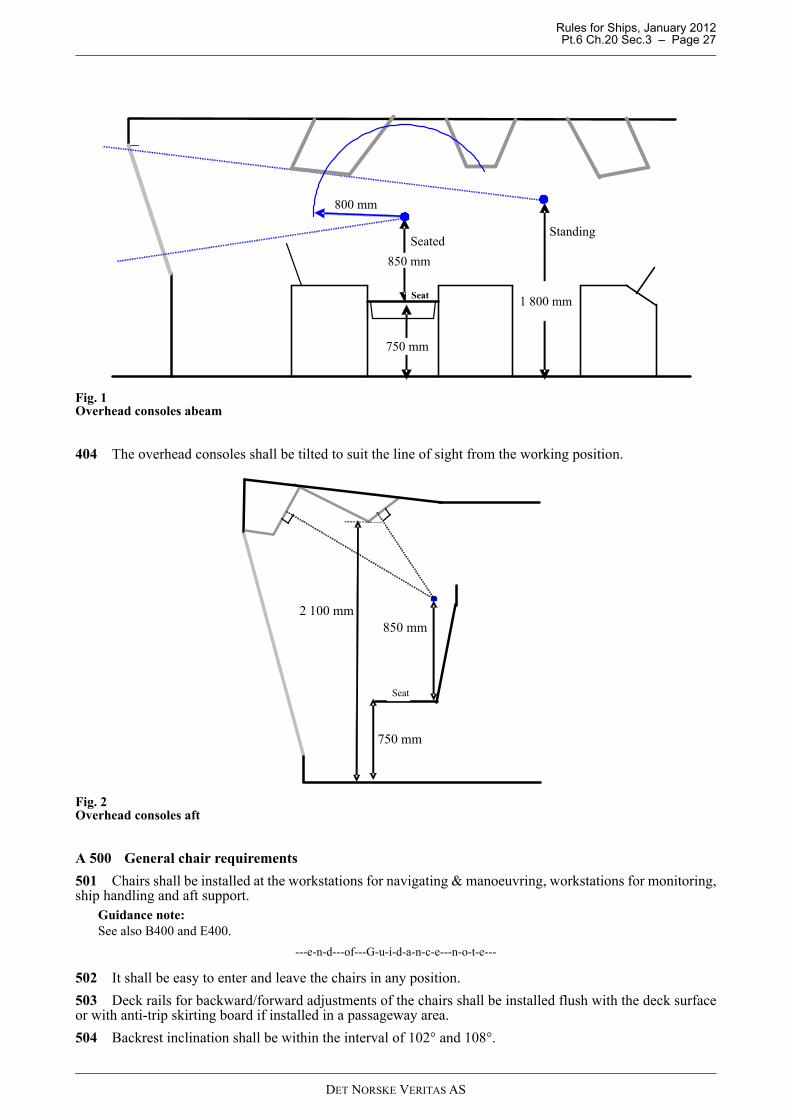
Rules for Ships, January 2012 Pt.6 Ch.20 Sec.3 – Page 27
Fig. 1Overhead consoles abeam
404 The overhead consoles shall be tilted to suit the line of sight from the working position.
Fig. 2Overhead consoles aft
A 500 General chair requirements
501 Chairs shall be installed at the workstations for navigating & manoeuvring, workstations for monitoring,ship handling and aft support.
Guidance note:See also B400 and E400.
---e-n-d---of---G-u-i-d-a-n-c-e---n-o-t-e---
502 It shall be easy to enter and leave the chairs in any position.
503 Deck rails for backward/forward adjustments of the chairs shall be installed flush with the deck surfaceor with anti-trip skirting board if installed in a passageway area.
504 Backrest inclination shall be within the interval of 102° and 108°.
850 mm
Seat
800 mm
SeatedStanding
1 800 mm
750 mm
850 mm
750 mm
2 100 mm
Seat
DET NORSKE VERITAS AS
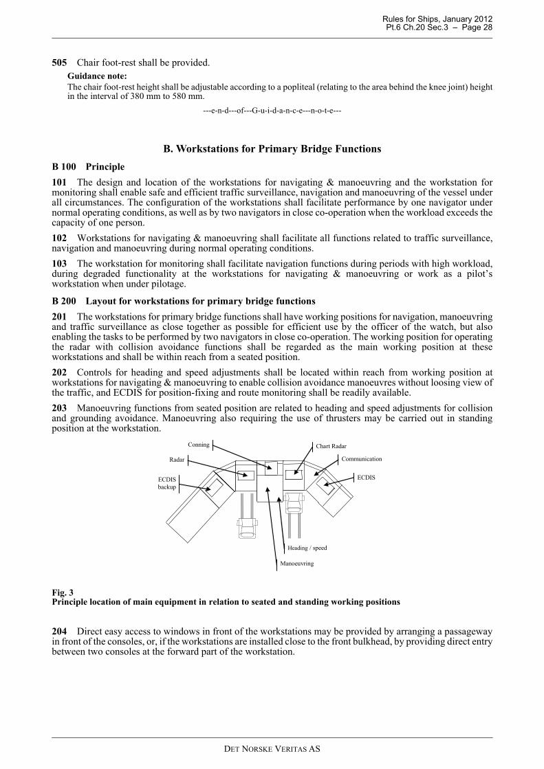
Rules for Ships, January 2012 Pt.6 Ch.20 Sec.3 – Page 28
505 Chair foot-rest shall be provided. Guidance note:The chair foot-rest height shall be adjustable according to a popliteal (relating to the area behind the knee joint) heightin the interval of 380 mm to 580 mm.
---e-n-d---of---G-u-i-d-a-n-c-e---n-o-t-e---
B. Workstations for Primary Bridge Functions
B 100 Principle
101 The design and location of the workstations for navigating & manoeuvring and the workstation formonitoring shall enable safe and efficient traffic surveillance, navigation and manoeuvring of the vessel underall circumstances. The configuration of the workstations shall facilitate performance by one navigator undernormal operating conditions, as well as by two navigators in close co-operation when the workload exceeds thecapacity of one person.
102 Workstations for navigating & manoeuvring shall facilitate all functions related to traffic surveillance,navigation and manoeuvring during normal operating conditions.
103 The workstation for monitoring shall facilitate navigation functions during periods with high workload,during degraded functionality at the workstations for navigating & manoeuvring or work as a pilot’sworkstation when under pilotage.
B 200 Layout for workstations for primary bridge functions
201 The workstations for primary bridge functions shall have working positions for navigation, manoeuvringand traffic surveillance as close together as possible for efficient use by the officer of the watch, but alsoenabling the tasks to be performed by two navigators in close co-operation. The working position for operatingthe radar with collision avoidance functions shall be regarded as the main working position at theseworkstations and shall be within reach from a seated position.
202 Controls for heading and speed adjustments shall be located within reach from working position atworkstations for navigating & manoeuvring to enable collision avoidance manoeuvres without loosing view ofthe traffic, and ECDIS for position-fixing and route monitoring shall be readily available.
203 Manoeuvring functions from seated position are related to heading and speed adjustments for collisionand grounding avoidance. Manoeuvring also requiring the use of thrusters may be carried out in standingposition at the workstation.
Fig. 3Principle location of main equipment in relation to seated and standing working positions
204 Direct easy access to windows in front of the workstations may be provided by arranging a passagewayin front of the consoles, or, if the workstations are installed close to the front bulkhead, by providing direct entrybetween two consoles at the forward part of the workstation.
ECDIS
Chart Radar
ECDIS backup
Heading / speed
Communication
Manoeuvring
Radar
Conning
DET NORSKE VERITAS AS
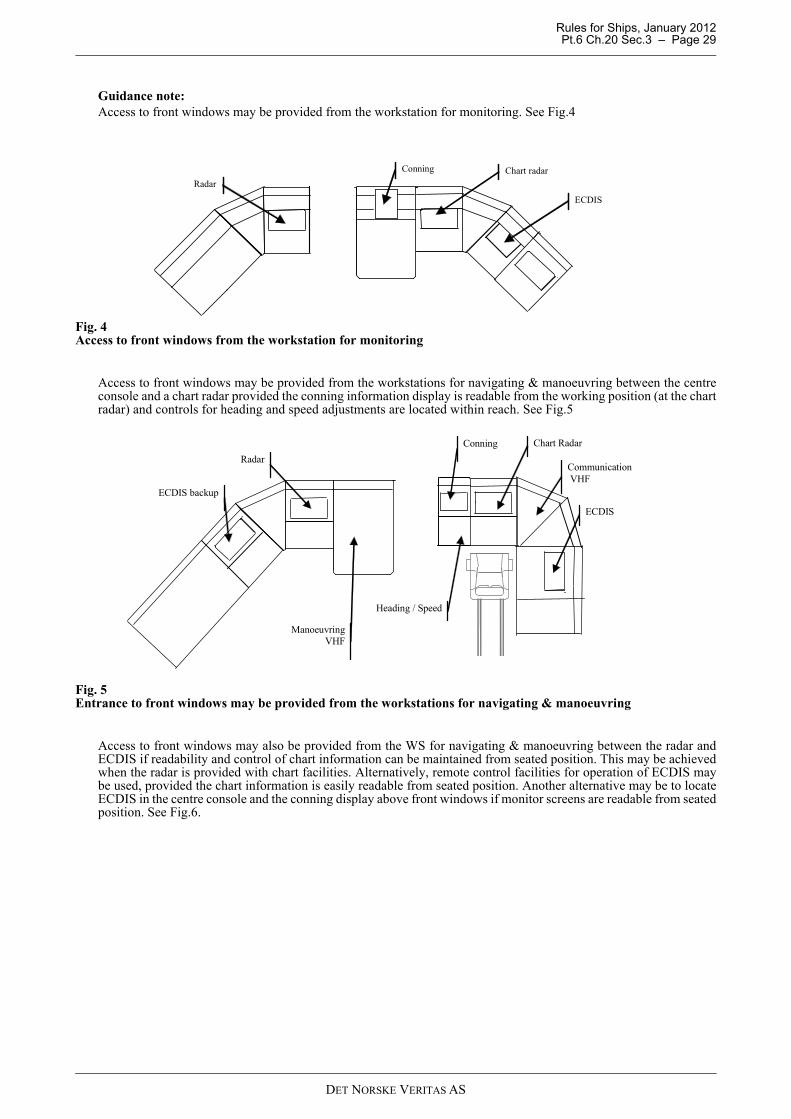
Rules for Ships, January 2012 Pt.6 Ch.20 Sec.3 – Page 29
Guidance note:Access to front windows may be provided from the workstation for monitoring. See Fig.4
Fig. 4Access to front windows from the workstation for monitoring
Access to front windows may be provided from the workstations for navigating & manoeuvring between the centreconsole and a chart radar provided the conning information display is readable from the working position (at the chartradar) and controls for heading and speed adjustments are located within reach. See Fig.5
Fig. 5Entrance to front windows may be provided from the workstations for navigating & manoeuvring
Access to front windows may also be provided from the WS for navigating & manoeuvring between the radar andECDIS if readability and control of chart information can be maintained from seated position. This may be achievedwhen the radar is provided with chart facilities. Alternatively, remote control facilities for operation of ECDIS maybe used, provided the chart information is easily readable from seated position. Another alternative may be to locateECDIS in the centre console and the conning display above front windows if monitor screens are readable from seatedposition. See Fig.6.
Radar
Conning Chart radar
ECDIS
ECDIS
Conning
Manoeuvring VHF
Heading / Speed
Communication VHF
Radar
ECDIS backup
Chart Radar
DET NORSKE VERITAS AS
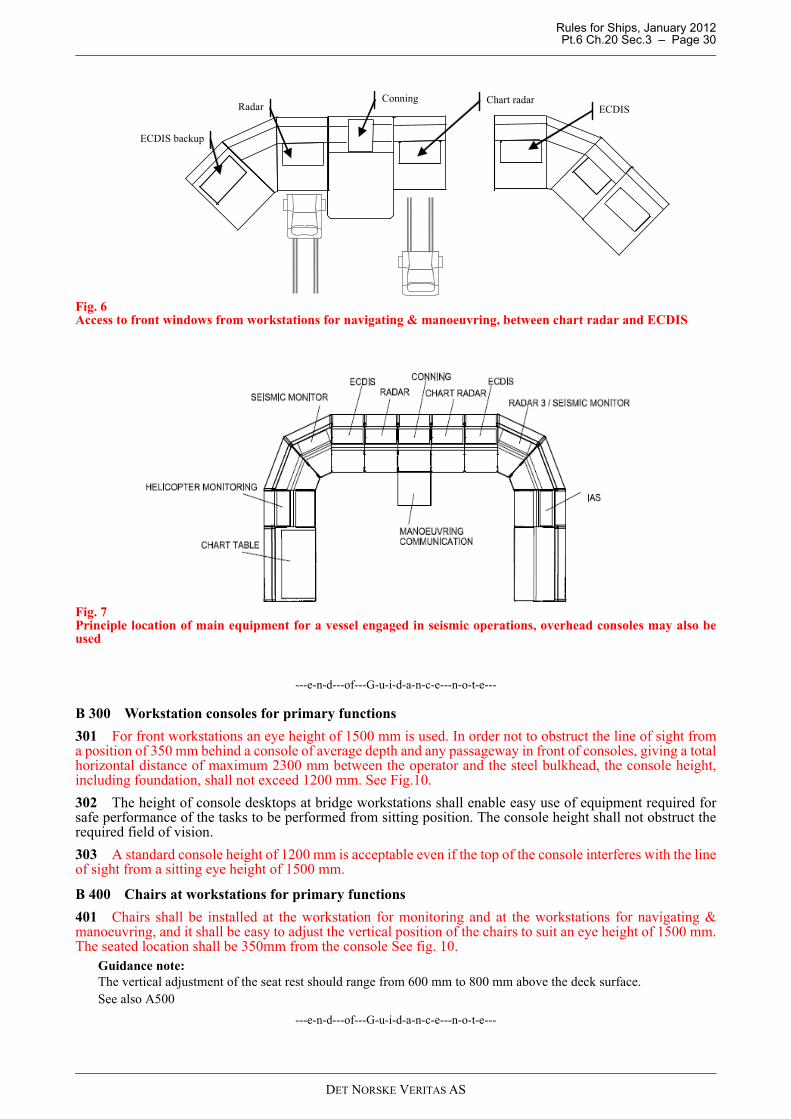
Rules for Ships, January 2012 Pt.6 Ch.20 Sec.3 – Page 30
Fig. 6Access to front windows from workstations for navigating & manoeuvring, between chart radar and ECDIS
Fig. 7Principle location of main equipment for a vessel engaged in seismic operations, overhead consoles may also beused
---e-n-d---of---G-u-i-d-a-n-c-e---n-o-t-e---
B 300 Workstation consoles for primary functions
301 For front workstations an eye height of 1500 mm is used. In order not to obstruct the line of sight froma position of 350 mm behind a console of average depth and any passageway in front of consoles, giving a totalhorizontal distance of maximum 2300 mm between the operator and the steel bulkhead, the console height,including foundation, shall not exceed 1200 mm. See Fig.10.
302 The height of console desktops at bridge workstations shall enable easy use of equipment required forsafe performance of the tasks to be performed from sitting position. The console height shall not obstruct therequired field of vision.
303 A standard console height of 1200 mm is acceptable even if the top of the console interferes with the lineof sight from a sitting eye height of 1500 mm.
B 400 Chairs at workstations for primary functions
401 Chairs shall be installed at the workstation for monitoring and at the workstations for navigating &manoeuvring, and it shall be easy to adjust the vertical position of the chairs to suit an eye height of 1500 mm.The seated location shall be 350mm from the console See fig. 10.
Guidance note:The vertical adjustment of the seat rest should range from 600 mm to 800 mm above the deck surface.See also A500
---e-n-d---of---G-u-i-d-a-n-c-e---n-o-t-e---
Radar Conning Chart radar
ECDIS
ECDIS backup
DET NORSKE VERITAS AS
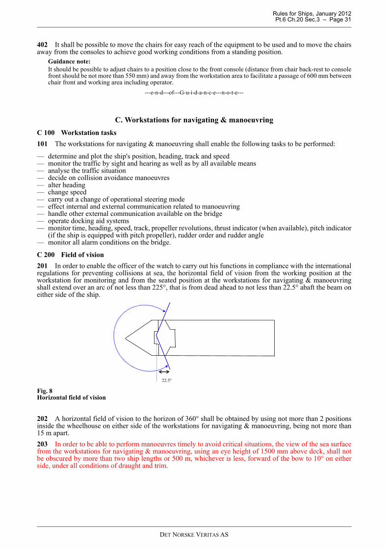
Rules for Ships, January 2012 Pt.6 Ch.20 Sec.3 – Page 31
402 It shall be possible to move the chairs for easy reach of the equipment to be used and to move the chairsaway from the consoles to achieve good working conditions from a standing position.
Guidance note:It should be possible to adjust chairs to a position close to the front console (distance from chair back-rest to consolefront should be not more than 550 mm) and away from the workstation area to facilitate a passage of 600 mm betweenchair front and working area including operator.
---e-n-d---of---G-u-i-d-a-n-c-e---n-o-t-e---
C. Workstations for navigating & manoeuvring
C 100 Workstation tasks
101 The workstations for navigating & manoeuvring shall enable the following tasks to be performed:
— determine and plot the ship's position, heading, track and speed— monitor the traffic by sight and hearing as well as by all available means— analyse the traffic situation— decide on collision avoidance manoeuvres— alter heading— change speed— carry out a change of operational steering mode— effect internal and external communication related to manoeuvring— handle other external communication available on the bridge— operate docking aid systems— monitor time, heading, speed, track, propeller revolutions, thrust indicator (when available), pitch indicator
(if the ship is equipped with pitch propeller), rudder order and rudder angle— monitor all alarm conditions on the bridge.
C 200 Field of vision
201 In order to enable the officer of the watch to carry out his functions in compliance with the internationalregulations for preventing collisions at sea, the horizontal field of vision from the working position at theworkstation for monitoring and from the seated position at the workstations for navigating & manoeuvringshall extend over an arc of not less than 225°, that is from dead ahead to not less than 22.5° abaft the beam oneither side of the ship.
Fig. 8Horizontal field of vision
202 A horizontal field of vision to the horizon of 360° shall be obtained by using not more than 2 positionsinside the wheelhouse on either side of the workstations for navigating & manoeuvring, being not more than15 m apart.
203 In order to be able to perform manoeuvres timely to avoid critical situations, the view of the sea surfacefrom the workstations for navigating & manoeuvring, using an eye height of 1500 mm above deck, shall notbe obscured by more than two ship lengths or 500 m, whichever is less, forward of the bow to 10° on eitherside, under all conditions of draught and trim.
22.5°
DET NORSKE VERITAS AS
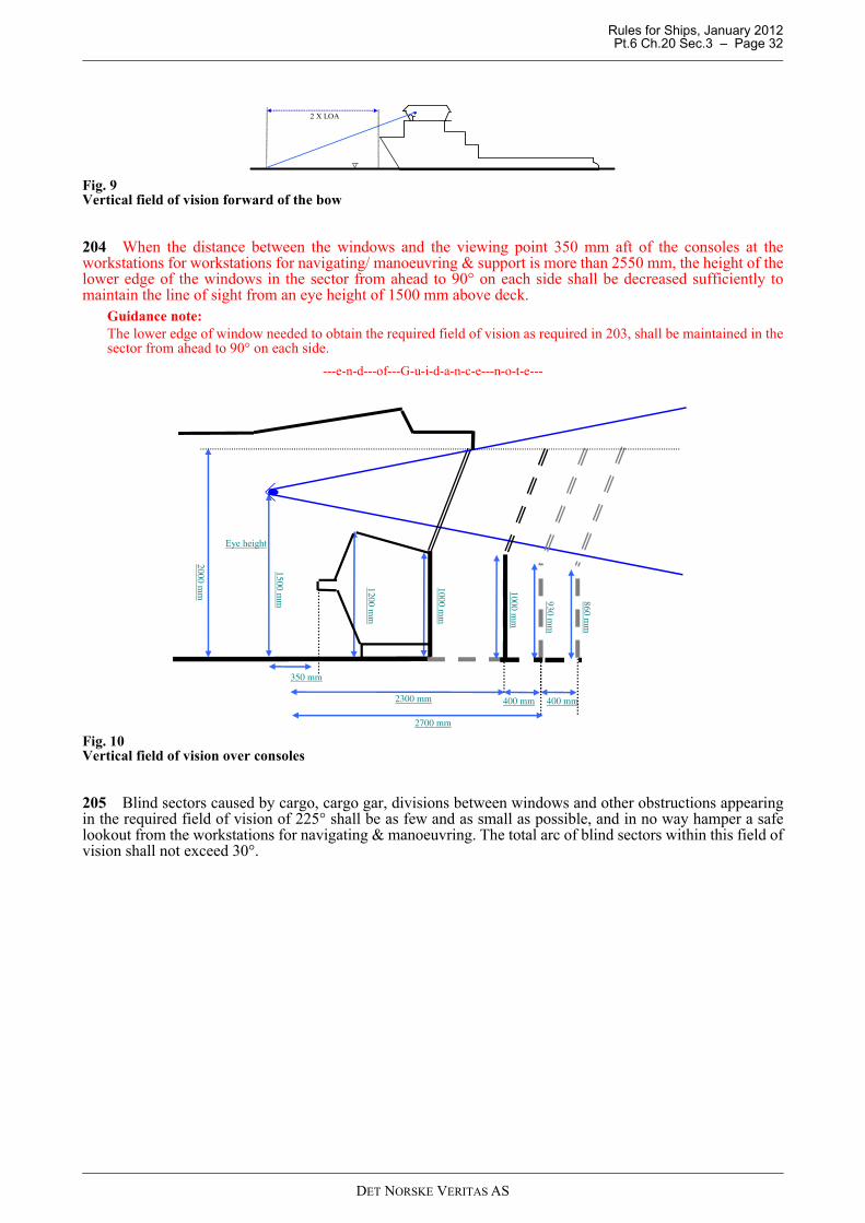
Rules for Ships, January 2012 Pt.6 Ch.20 Sec.3 – Page 32
Fig. 9Vertical field of vision forward of the bow
204 When the distance between the windows and the viewing point 350 mm aft of the consoles at theworkstations for workstations for navigating/ manoeuvring & support is more than 2550 mm, the height of thelower edge of the windows in the sector from ahead to 90° on each side shall be decreased sufficiently tomaintain the line of sight from an eye height of 1500 mm above deck.
Guidance note:The lower edge of window needed to obtain the required field of vision as required in 203, shall be maintained in thesector from ahead to 90° on each side.
---e-n-d---of---G-u-i-d-a-n-c-e---n-o-t-e---
Fig. 10Vertical field of vision over consoles
205 Blind sectors caused by cargo, cargo gar, divisions between windows and other obstructions appearingin the required field of vision of 225° shall be as few and as small as possible, and in no way hamper a safelookout from the workstations for navigating & manoeuvring. The total arc of blind sectors within this field ofvision shall not exceed 30°.
2 X LOA
2700 mm
2300 mm 400 mm
930 mm
1200 mm
2000 mm
1000 mm
Eye height
1500 mm
350 mm
1000 mm
400 mm
860 mm
DET NORSKE VERITAS AS
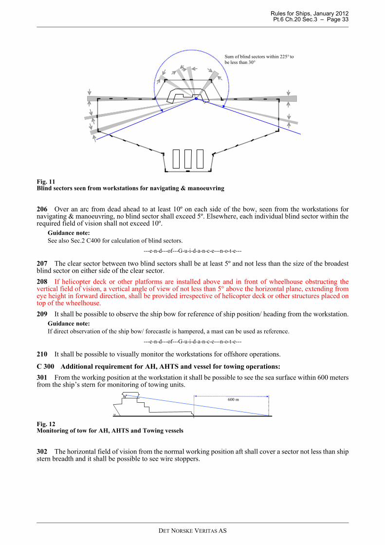
Rules for Ships, January 2012 Pt.6 Ch.20 Sec.3 – Page 33
Fig. 11Blind sectors seen from workstations for navigating & manoeuvring
206 Over an arc from dead ahead to at least 10º on each side of the bow, seen from the workstations fornavigating & manoeuvring, no blind sector shall exceed 5º. Elsewhere, each individual blind sector within therequired field of vision shall not exceed 10º.
Guidance note:See also Sec.2 C400 for calculation of blind sectors.
---e-n-d---of---G-u-i-d-a-n-c-e---n-o-t-e---
207 The clear sector between two blind sectors shall be at least 5º and not less than the size of the broadestblind sector on either side of the clear sector.
208 If helicopter deck or other platforms are installed above and in front of wheelhouse obstructing thevertical field of vision, a vertical angle of view of not less than 5° above the horizontal plane, extending fromeye height in forward direction, shall be provided irrespective of helicopter deck or other structures placed ontop of the wheelhouse.
209 It shall be possible to observe the ship bow for reference of ship position/ heading from the workstation.Guidance note:If direct observation of the ship bow/ forecastle is hampered, a mast can be used as reference.
---e-n-d---of---G-u-i-d-a-n-c-e---n-o-t-e---
210 It shall be possible to visually monitor the workstations for offshore operations.
C 300 Additional requirement for AH, AHTS and vessel for towing operations:
301 From the working position at the workstation it shall be possible to see the sea surface within 600 metersfrom the ship’s stern for monitoring of towing units.
Fig. 12Monitoring of tow for AH, AHTS and Towing vessels
302 The horizontal field of vision from the normal working position aft shall cover a sector not less than shipstern breadth and it shall be possible to see wire stoppers.
Sum of blind sectors within 225° tobe less than 30°
600 m
DET NORSKE VERITAS AS
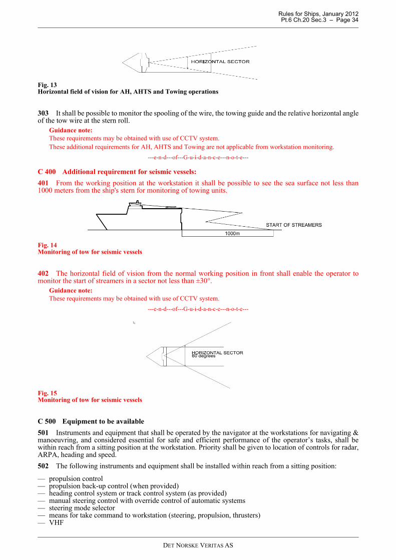
Rules for Ships, January 2012 Pt.6 Ch.20 Sec.3 – Page 34
Fig. 13Horizontal field of vision for AH, AHTS and Towing operations
303 It shall be possible to monitor the spooling of the wire, the towing guide and the relative horizontal angleof the tow wire at the stern roll.
Guidance note:These requirements may be obtained with use of CCTV system.These additional requirements for AH, AHTS and Towing are not applicable from workstation monitoring.
---e-n-d---of---G-u-i-d-a-n-c-e---n-o-t-e---
C 400 Additional requirement for seismic vessels:
401 From the working position at the workstation it shall be possible to see the sea surface not less than1000 meters from the ship's stern for monitoring of towing units.
Fig. 14Monitoring of tow for seismic vessels
402 The horizontal field of vision from the normal working position in front shall enable the operator tomonitor the start of streamers in a sector not less than ±30°.
Guidance note:These requirements may be obtained with use of CCTV system.
---e-n-d---of---G-u-i-d-a-n-c-e---n-o-t-e---
Fig. 15Monitoring of tow for seismic vessels
C 500 Equipment to be available
501 Instruments and equipment that shall be operated by the navigator at the workstations for navigating &manoeuvring, and considered essential for safe and efficient performance of the operator’s tasks, shall bewithin reach from a sitting position at the workstation. Priority shall be given to location of controls for radar,ARPA, heading and speed.
502 The following instruments and equipment shall be installed within reach from a sitting position:
— propulsion control — propulsion back-up control (when provided)— heading control system or track control system (as provided)— manual steering control with override control of automatic systems— steering mode selector— means for take command to workstation (steering, propulsion, thrusters)— VHF
DET NORSKE VERITAS AS
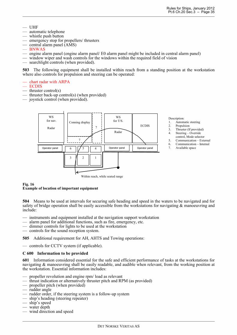
Rules for Ships, January 2012 Pt.6 Ch.20 Sec.3 – Page 35
— UHF— automatic telephone— whistle push button— emergency stop for propellers/ thrusters — central alarm panel (AMS)— BNWAS— engine alarm panel (engine alarm panel/ E0 alarm panel might be included in central alarm panel)— window wiper and wash controls for the windows within the required field of vision— searchlight controls (when provided).
503 The following equipment shall be installed within reach from a standing position at the workstationwhere also controls for propulsion and steering can be operated:
— chart radar with ARPA— ECDIS— thruster control(s)— thruster back-up control(s) (when provided)— joystick control (when provided).
Fig. 16Example of location of important equipment
504 Means to be used at intervals for securing safe heading and speed in the waters to be navigated and forsafety of bridge operation shall be easily accessible from the workstations for navigating & manoeuvring andinclude:
— instruments and equipment installed at the navigation support workstation— alarm panel for additional functions, such as fire, emergency, etc.— dimmer controls for lights to be used at the workstation— controls for the sound reception system.
505 Additional requirement for AH, AHTS and Towing operations:
— controls for CCTV system (if applicable).
C 600 Information to be provided
601 Information considered essential for the safe and efficient performance of tasks at the workstations fornavigating & manoeuvring shall be easily readable, and audible when relevant, from the working position atthe workstation. Essential information includes:
— propeller revolution and engine rpm/ load as relevant— thrust indication or alternatively thruster pitch and RPM (as provided)— propeller pitch (when provided)— rudder angle— rudder order, if the steering system is a follow-up system— ship’s heading (steering repeater)— ship’s speed— water depth— wind direction and speed
Description: 1. Automatic steering 2. Propulsion 3. Thruster (If provided) 4. Steering – Override
control, Mode selector 5. Communication – External 6. Communication – Internal 7. Available space
ECDIS
Within reach, while seated range
1 2 3
5
Conning display
4 6
7
7
WS for nav.
Radar
WS for T/S.
Radar
Operator panel Operator panel Operator panel
DET NORSKE VERITAS AS
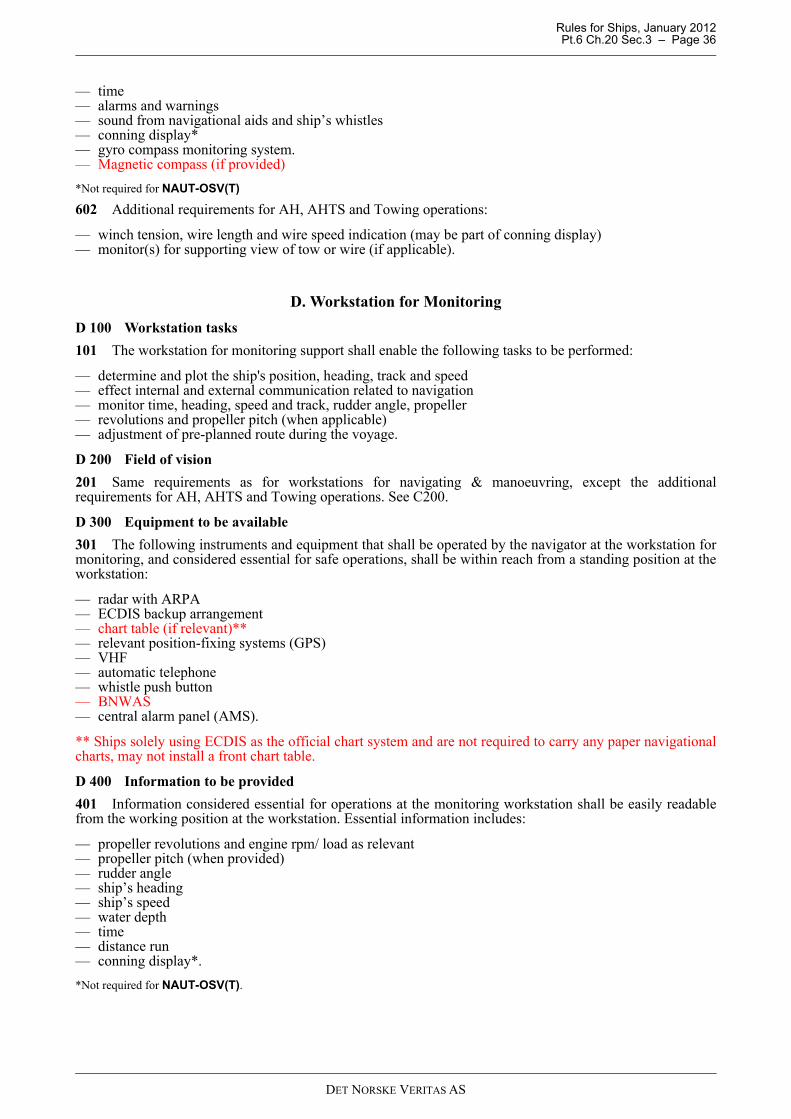
Rules for Ships, January 2012 Pt.6 Ch.20 Sec.3 – Page 36
— time— alarms and warnings— sound from navigational aids and ship’s whistles— conning display*— gyro compass monitoring system.— Magnetic compass (if provided)
*Not required for NAUT-OSV(T)
602 Additional requirements for AH, AHTS and Towing operations:
— winch tension, wire length and wire speed indication (may be part of conning display)— monitor(s) for supporting view of tow or wire (if applicable).
D. Workstation for Monitoring
D 100 Workstation tasks
101 The workstation for monitoring support shall enable the following tasks to be performed:
— determine and plot the ship's position, heading, track and speed— effect internal and external communication related to navigation— monitor time, heading, speed and track, rudder angle, propeller— revolutions and propeller pitch (when applicable)— adjustment of pre-planned route during the voyage.
D 200 Field of vision
201 Same requirements as for workstations for navigating & manoeuvring, except the additionalrequirements for AH, AHTS and Towing operations. See C200.
D 300 Equipment to be available
301 The following instruments and equipment that shall be operated by the navigator at the workstation formonitoring, and considered essential for safe operations, shall be within reach from a standing position at theworkstation:
— radar with ARPA — ECDIS backup arrangement— chart table (if relevant)**— relevant position-fixing systems (GPS)— VHF— automatic telephone— whistle push button— BNWAS— central alarm panel (AMS).
** Ships solely using ECDIS as the official chart system and are not required to carry any paper navigationalcharts, may not install a front chart table.
D 400 Information to be provided
401 Information considered essential for operations at the monitoring workstation shall be easily readablefrom the working position at the workstation. Essential information includes:
— propeller revolutions and engine rpm/ load as relevant— propeller pitch (when provided)— rudder angle — ship’s heading— ship’s speed— water depth— time— distance run— conning display*.
*Not required for NAUT-OSV(T).
DET NORSKE VERITAS AS
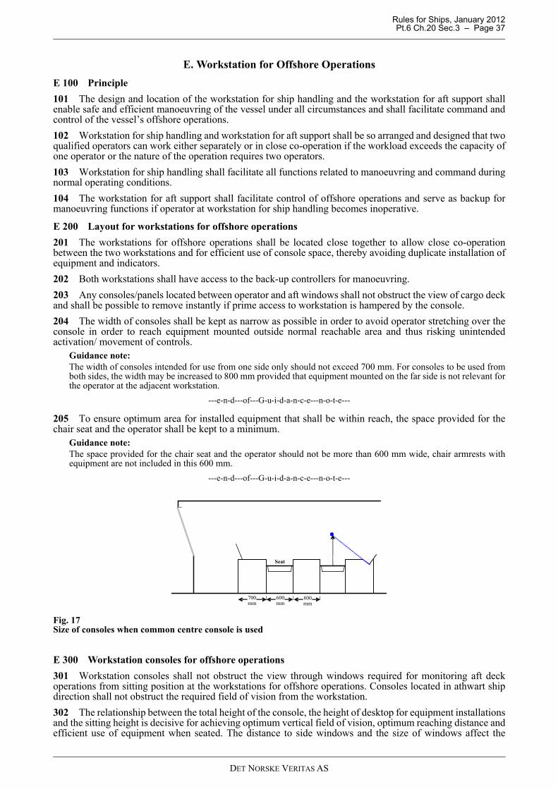
Rules for Ships, January 2012 Pt.6 Ch.20 Sec.3 – Page 37
E. Workstation for Offshore Operations
E 100 Principle
101 The design and location of the workstation for ship handling and the workstation for aft support shallenable safe and efficient manoeuvring of the vessel under all circumstances and shall facilitate command andcontrol of the vessel’s offshore operations.
102 Workstation for ship handling and workstation for aft support shall be so arranged and designed that twoqualified operators can work either separately or in close co-operation if the workload exceeds the capacity ofone operator or the nature of the operation requires two operators.
103 Workstation for ship handling shall facilitate all functions related to manoeuvring and command duringnormal operating conditions.
104 The workstation for aft support shall facilitate control of offshore operations and serve as backup formanoeuvring functions if operator at workstation for ship handling becomes inoperative.
E 200 Layout for workstations for offshore operations
201 The workstations for offshore operations shall be located close together to allow close co-operationbetween the two workstations and for efficient use of console space, thereby avoiding duplicate installation ofequipment and indicators.
202 Both workstations shall have access to the back-up controllers for manoeuvring.
203 Any consoles/panels located between operator and aft windows shall not obstruct the view of cargo deckand shall be possible to remove instantly if prime access to workstation is hampered by the console.
204 The width of consoles shall be kept as narrow as possible in order to avoid operator stretching over theconsole in order to reach equipment mounted outside normal reachable area and thus risking unintendedactivation/ movement of controls.
Guidance note:The width of consoles intended for use from one side only should not exceed 700 mm. For consoles to be used fromboth sides, the width may be increased to 800 mm provided that equipment mounted on the far side is not relevant forthe operator at the adjacent workstation.
---e-n-d---of---G-u-i-d-a-n-c-e---n-o-t-e---
205 To ensure optimum area for installed equipment that shall be within reach, the space provided for thechair seat and the operator shall be kept to a minimum.
Guidance note:The space provided for the chair seat and the operator should not be more than 600 mm wide, chair armrests withequipment are not included in this 600 mm.
---e-n-d---of---G-u-i-d-a-n-c-e---n-o-t-e---
Fig. 17Size of consoles when common centre console is used
E 300 Workstation consoles for offshore operations
301 Workstation consoles shall not obstruct the view through windows required for monitoring aft deckoperations from sitting position at the workstations for offshore operations. Consoles located in athwart shipdirection shall not obstruct the required field of vision from the workstation.
302 The relationship between the total height of the console, the height of desktop for equipment installationsand the sitting height is decisive for achieving optimum vertical field of vision, optimum reaching distance andefficient use of equipment when seated. The distance to side windows and the size of windows affect the
Seat
800mm
700mm
600mm
DET NORSKE VERITAS AS
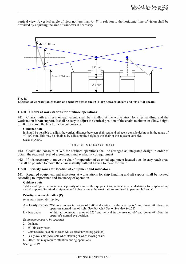
Rules for Ships, January 2012 Pt.6 Ch.20 Sec.3 – Page 38
vertical view. A vertical angle of view not less than +/- 5° in relation to the horizontal line of vision shall beprovided by adjusting the size of windows if necessary.
Fig. 18Location of workstation consoles and window size in the FOV arc between abeam and 30° aft of abeam.
E 400 Chairs at workstations for offshore operations
401 Chairs, with armrests or equivalent, shall be installed at the workstation for ship handling and theworkstation for aft support. It shall be easy to adjust the vertical position of the chairs to obtain an elbow heightof 50 mm above the level of adjacent consoles.
Guidance note:It should be possible to adjust the vertical distance between chair seat and adjacent console desktops in the range of+/- 100 mm. This may be obtained by adjusting the height of the chair or the adjacent consoles.See also A500.
---e-n-d---of---G-u-i-d-a-n-c-e---n-o-t-e---
402 Chairs and consoles at WS for offshore operations shall be arranged as integrated design in order toobtain the required level of ergonomics and availability of equipment
403 If it is necessary to move the chair for operation of essential equipment located outside easy reach area,it shall be possible to move the chair instantly without having to leave the chair.
E 500 Priority zones for location of equipment and indicators
501 Required equipment and indicators at workstations for ship handling and aft support shall be locatedaccording to importance and frequency of operation.
Guidance note:Tables and figure below indicates priority of some of the equipment and indicators at workstations for ship handlingand aft support. Required equipment and information at the workstations are listed in paragraph F and G.
Priority zones explanation (P):Indicators meant for reading
A – Easily readableWithin a horizontal sector of 180° and vertical in the area up 60° and down 90° from theoperators normal line of sight. See Pt.4 Ch.9 Sec.6. See also Sec.5 D
B - Readable Within an horizontal sector of 225° and vertical in the area up 60° and down 90° from theoperator’s normal eye position.
Equipment meant to be operated2 – On hand3 – Within easy reach4 – Within reach (Possible to reach while seated in working position)5 – Easily available (Available when standing or when moving chair)6 – Other that may require attention during operationsSee figure 19
Seat
Min. 2 000 mm
5°
Max. 1 000 mm
5°
850 mm
750 mm
DET NORSKE VERITAS AS
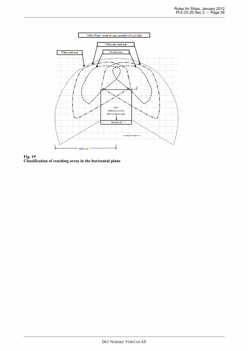
Rules for Ships, January 2012 Pt.6 Ch.20 Sec.3 – Page 39
Fig. 19Classification of reaching areas in the horizontal plane
DET NORSKE VERITAS AS
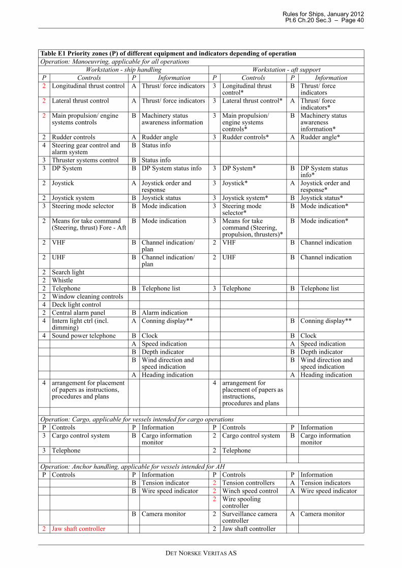
Rules for Ships, January 2012 Pt.6 Ch.20 Sec.3 – Page 40
Table E1 Priority zones (P) of different equipment and indicators depending of operationOperation: Manoeuvring, applicable for all operations
Workstation - ship handling Workstation - aft supportP Controls P Information P Controls P Information2 Longitudinal thrust control A Thrust/ force indicators 3 Longitudinal thrust
control*B Thrust/ force
indicators2 Lateral thrust control A Thrust/ force indicators 3 Lateral thrust control* A Thrust/ force
indicators*2 Main propulsion/ engine
systems controlsB Machinery status
awareness information3 Main propulsion/
engine systems controls*
B Machinery status awareness information*
2 Rudder controls A Rudder angle 3 Rudder controls* A Rudder angle*4 Steering gear control and
alarm systemB Status info
3 Thruster systems control B Status info3 DP System B DP System status info 3 DP System* B DP System status
info*2 Joystick A Joystick order and
response3 Joystick* A Joystick order and
response*2 Joystick system B Joystick status 3 Joystick system* B Joystick status*3 Steering mode selector B Mode indication 3 Steering mode
selector*B Mode indication*
2 Means for take command (Steering, thrust) Fore - Aft
B Mode indication 3 Means for take command (Steering, propulsion, thrusters)*
B Mode indication*
2 VHF B Channel indication/ plan
2 VHF B Channel indication
2 UHF B Channel indication/ plan
2 UHF B Channel indication
2 Search light2 Whistle2 Telephone B Telephone list 3 Telephone B Telephone list2 Window cleaning controls4 Deck light control 2 Central alarm panel B Alarm indication4 Intern light ctrl (incl.
dimming)A Conning display** B Conning display**
4 Sound power telephone B Clock B ClockA Speed indication A Speed indicationB Depth indicator B Depth indicatorB Wind direction and
speed indicationB Wind direction and
speed indicationA Heading indication A Heading indication
4 arrangement for placement of papers as instructions, procedures and plans
4 arrangement for placement of papers as instructions, procedures and plans
Operation: Cargo, applicable for vessels intended for cargo operationsP Controls P Information P Controls P Information3 Cargo control system B Cargo information
monitor2 Cargo control system B Cargo information
monitor3 Telephone 2 Telephone
Operation: Anchor handling, applicable for vessels intended for AHP Controls P Information P Controls P Information
B Tension indicator 2 Tension controllers A Tension indicatorsB Wire speed indicator 2 Winch speed control A Wire speed indicator
2 Wire spooling controller
B Camera monitor 2 Surveillance camera controller
A Camera monitor
2 Jaw shaft controller 2 Jaw shaft controller
DET NORSKE VERITAS AS
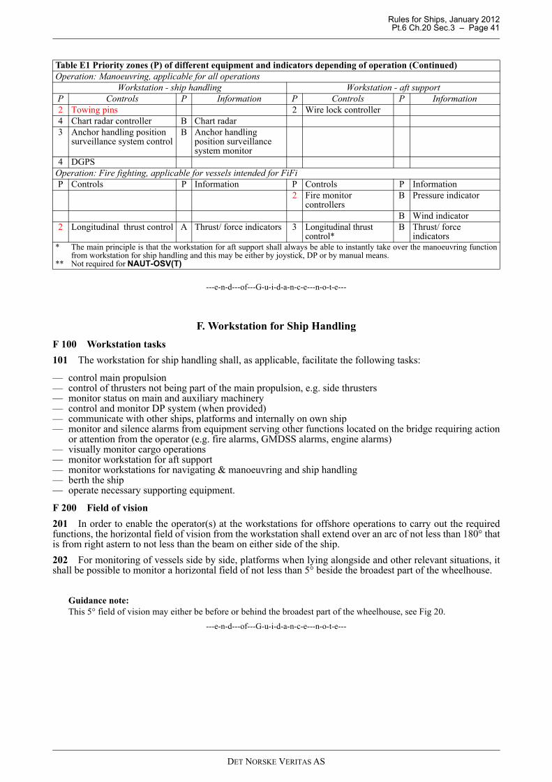
Rules for Ships, January 2012 Pt.6 Ch.20 Sec.3 – Page 41
---e-n-d---of---G-u-i-d-a-n-c-e---n-o-t-e---
F. Workstation for Ship Handling
F 100 Workstation tasks
101 The workstation for ship handling shall, as applicable, facilitate the following tasks:
— control main propulsion— control of thrusters not being part of the main propulsion, e.g. side thrusters— monitor status on main and auxiliary machinery— control and monitor DP system (when provided)— communicate with other ships, platforms and internally on own ship— monitor and silence alarms from equipment serving other functions located on the bridge requiring action
or attention from the operator (e.g. fire alarms, GMDSS alarms, engine alarms)— visually monitor cargo operations— monitor workstation for aft support— monitor workstations for navigating & manoeuvring and ship handling— berth the ship— operate necessary supporting equipment.
F 200 Field of vision
201 In order to enable the operator(s) at the workstations for offshore operations to carry out the requiredfunctions, the horizontal field of vision from the workstation shall extend over an arc of not less than 180° thatis from right astern to not less than the beam on either side of the ship.
202 For monitoring of vessels side by side, platforms when lying alongside and other relevant situations, itshall be possible to monitor a horizontal field of not less than 5° beside the broadest part of the wheelhouse.
Guidance note:This 5° field of vision may either be before or behind the broadest part of the wheelhouse, see Fig 20.
---e-n-d---of---G-u-i-d-a-n-c-e---n-o-t-e---
2 Towing pins 2 Wire lock controller4 Chart radar controller B Chart radar3 Anchor handling position
surveillance system controlB Anchor handling
position surveillance system monitor
4 DGPSOperation: Fire fighting, applicable for vessels intended for FiFiP Controls P Information P Controls P Information
2 Fire monitor controllers
B Pressure indicator
B Wind indicator2 Longitudinal thrust control A Thrust/ force indicators 3 Longitudinal thrust
control*B Thrust/ force
indicators* The main principle is that the workstation for aft support shall always be able to instantly take over the manoeuvring function
from workstation for ship handling and this may be either by joystick, DP or by manual means.** Not required for NAUT-OSV(T)
Table E1 Priority zones (P) of different equipment and indicators depending of operation (Continued)Operation: Manoeuvring, applicable for all operations
Workstation - ship handling Workstation - aft supportP Controls P Information P Controls P Information
DET NORSKE VERITAS AS
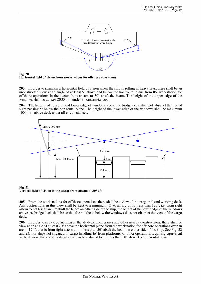
Rules for Ships, January 2012 Pt.6 Ch.20 Sec.3 – Page 42
Fig. 20Horizontal field of vision from workstations for offshore operations
203 In order to maintain a horizontal field of vision when the ship is rolling in heavy seas, there shall be anunobstructed view at an angle of at least 5° above and below the horizontal plane from the workstation foroffshore operations in the sector from abeam to 30° abaft the beam. The height of the upper edge of thewindows shall be at least 2000 mm under all circumstances.
204 The heights of consoles and lower edge of windows above the bridge deck shall not obstruct the line ofsight passing 5° below the horizontal plane. The height of the lower edge of the windows shall be maximum1000 mm above deck under all circumstances.
Fig. 21Vertical field of vision in the sector from abeam to 30° aft
205 From the workstations for offshore operations there shall be a view of the cargo rail and working deck.Any obstructions in this view shall be kept to a minimum. Over an arc of not less than 120°, i.e. from rightastern to not less than 30° abaft the beam on either side of the ship, the height of the lower edge of the windowsabove the bridge deck shall be so that the bulkhead below the windows does not obstruct the view of the cargodeck.
206 In order to see cargo arriving at the aft deck from cranes and other nearby constructions, there shall beview at an angle of at least 20° above the horizontal plane from the workstation for offshore operations over anarc of 120°, that is from right astern to not less than 30° abaft the beam on either side of the ship. See Fig. 22and 23. For ships not engaged in cargo handling to/ from platforms, or other operations requiring equivalentvertical view, the above vertical view can be reduced to not less than 10° above the horizontal plane.
5°
180°
5°5° field of vision to monitor thebroadest part of wheelhouse
Seat
Min. 2 000 mm
5°
5°
Max. 1000 mm
850 mm
750 mm
DET NORSKE VERITAS AS
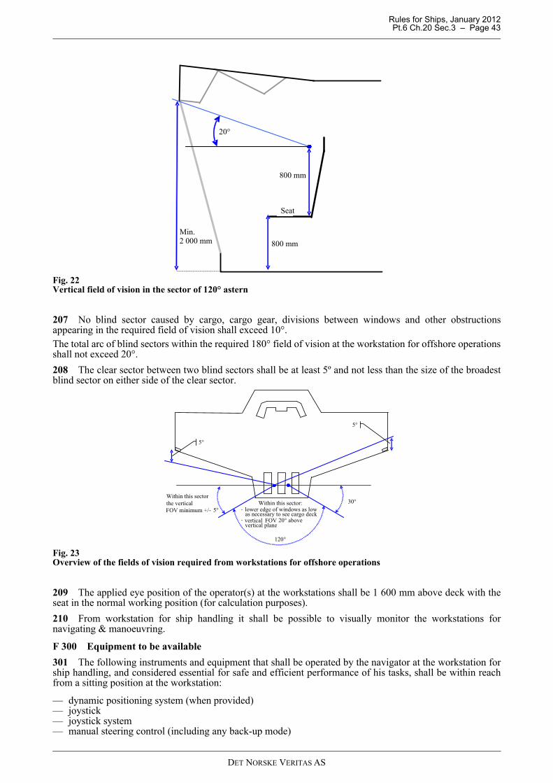
Rules for Ships, January 2012 Pt.6 Ch.20 Sec.3 – Page 43
Fig. 22Vertical field of vision in the sector of 120° astern
207 No blind sector caused by cargo, cargo gear, divisions between windows and other obstructionsappearing in the required field of vision shall exceed 10°.The total arc of blind sectors within the required 180° field of vision at the workstation for offshore operationsshall not exceed 20°.
208 The clear sector between two blind sectors shall be at least 5º and not less than the size of the broadestblind sector on either side of the clear sector.
Fig. 23Overview of the fields of vision required from workstations for offshore operations
209 The applied eye position of the operator(s) at the workstations shall be 1 600 mm above deck with theseat in the normal working position (for calculation purposes).
210 From workstation for ship handling it shall be possible to visually monitor the workstations fornavigating & manoeuvring.
F 300 Equipment to be available
301 The following instruments and equipment that shall be operated by the navigator at the workstation forship handling, and considered essential for safe and efficient performance of his tasks, shall be within reachfrom a sitting position at the workstation:
— dynamic positioning system (when provided)— joystick— joystick system— manual steering control (including any back-up mode)
800 mm
Seat
20°
Min.2 000 mm
800 mm
120°
5°
5°
30°Within this sectorthe verticalFOV minimum +/- 5°
Within this sector:
as necessary to see cargo deck- lower edge of windows as low
- vertical FOV 20° abovevertical plane
DET NORSKE VERITAS AS
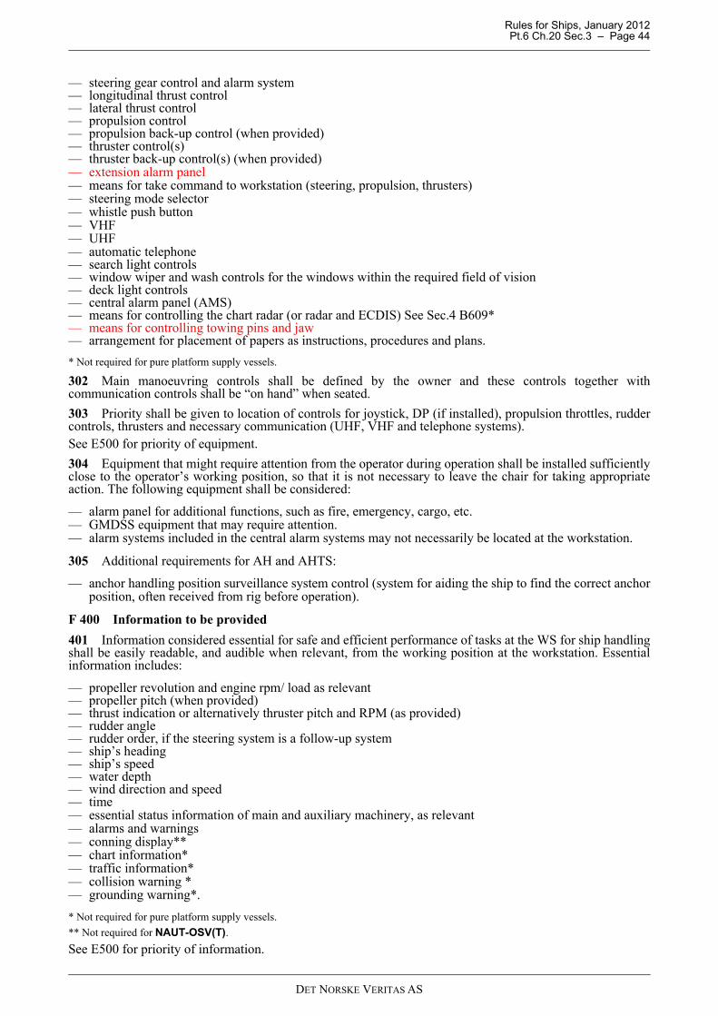
Rules for Ships, January 2012 Pt.6 Ch.20 Sec.3 – Page 44
— steering gear control and alarm system— longitudinal thrust control— lateral thrust control— propulsion control— propulsion back-up control (when provided)— thruster control(s)— thruster back-up control(s) (when provided)— extension alarm panel— means for take command to workstation (steering, propulsion, thrusters)— steering mode selector— whistle push button— VHF— UHF— automatic telephone — search light controls— window wiper and wash controls for the windows within the required field of vision— deck light controls— central alarm panel (AMS)— means for controlling the chart radar (or radar and ECDIS) See Sec.4 B609* — means for controlling towing pins and jaw — arrangement for placement of papers as instructions, procedures and plans.
* Not required for pure platform supply vessels.
302 Main manoeuvring controls shall be defined by the owner and these controls together withcommunication controls shall be “on hand” when seated.
303 Priority shall be given to location of controls for joystick, DP (if installed), propulsion throttles, ruddercontrols, thrusters and necessary communication (UHF, VHF and telephone systems). See E500 for priority of equipment.
304 Equipment that might require attention from the operator during operation shall be installed sufficientlyclose to the operator’s working position, so that it is not necessary to leave the chair for taking appropriateaction. The following equipment shall be considered:
— alarm panel for additional functions, such as fire, emergency, cargo, etc.— GMDSS equipment that may require attention.— alarm systems included in the central alarm systems may not necessarily be located at the workstation.
305 Additional requirements for AH and AHTS:
— anchor handling position surveillance system control (system for aiding the ship to find the correct anchorposition, often received from rig before operation).
F 400 Information to be provided
401 Information considered essential for safe and efficient performance of tasks at the WS for ship handlingshall be easily readable, and audible when relevant, from the working position at the workstation. Essentialinformation includes:
— propeller revolution and engine rpm/ load as relevant— propeller pitch (when provided)— thrust indication or alternatively thruster pitch and RPM (as provided)— rudder angle— rudder order, if the steering system is a follow-up system— ship’s heading— ship’s speed— water depth— wind direction and speed— time— essential status information of main and auxiliary machinery, as relevant— alarms and warnings— conning display**— chart information*— traffic information*— collision warning *— grounding warning*.
* Not required for pure platform supply vessels.
** Not required for NAUT-OSV(T).
See E500 for priority of information.
DET NORSKE VERITAS AS
Rules for Ships, January 2012 Pt.6 Ch.20 Sec.3 – Page 45
402 Additional requirements for AH, AHTS and Towing:
— essential winch information (tension, length, wire speed)— CCTV monitors for monitoring of winch equipment and spooling apparatus.
G. Workstation for Aft Support
G 100 Workstation tasks
101 The workstation for aft support shall facilitate the following tasks:
— control main propulsion for backup of manoeuvring function— control of thrusters not being part of the main propulsion, e.g. side thrusters, for backup of manoeuvring
function— monitor status on main and auxiliary machinery, as relevant— communicate with other ships, platforms and internal on vessel— monitor and control cargo operations— emergency stop of cargo operations— control and monitor winch operations, as relevant— monitor workstation for ship handling.
G 200 Field of vision
201 Same requirements as for workstation for ship handling, see F200.
G 300 Equipment to be available
301 The following instruments and equipment that shall be operated by the navigator at the workstation foraft support, and considered essential for safe and efficient performance of his tasks, shall be within reach froma sitting position at the workstation:
— joystick *— manual steering control (including any back-up mode)*— propulsion control *— propulsion back-up control (when provided)*— thruster control*— means for take command to workstation (steering, propulsion, thrusters)*— VHF— UHF— automatic telephone — central alarm panel — means for controlling towing pins and jaw— cargo operation system— auxiliary equipment needed for the relevant operations— arrangement for placement of papers as instructions, procedures and plans.
* The main principle is that the workstation for aft support shall always be able to instantly take over the manoeuvring function fromworkstation for ship handling and this may be either by joystick, DP or by manual means.
302 Priority shall be given to location of controls for propulsion, steering and thrusters and equipmentnecessary for the relevant operations. Equipment shall be prioritized in order of frequency in use andimportance.See E500 for priority of equipment.
303 Equipment that might require attention from the operator during operation shall be installed sufficientlyclose to the operator’s position so that it is not necessary to leave the workstation for taking appropriate action.
304 Additional requirements for AH, AHTS and Towing:
— winch control system— auxiliary systems for use during AH, AHTS and Towing operations— controls for CCTV monitors for winch and spooling apparatus monitoring.
G 400 Information to be provided
401 Information considered essential for safe and efficient performance of tasks at the WS for aft supportshall be easily readable, and audible when relevant, from the working position at the workstation. Essentialinformation includes:
— propeller revolution and engine rpm/ load as relevant
DET NORSKE VERITAS AS
Rules for Ships, January 2012 Pt.6 Ch.20 Sec.3 – Page 46
— propeller pitch (when provided)— thrust indication or alternatively thruster pitch and RPM (as provided)— rudder angle— rudder order, if the steering system is a follow-up system— ship’s heading— ship’s speed— water depth— wind direction and speed— time— conning display*.
*Not required for NAUT-OSV(T).
See E500 for priority of information.
402 In addition, information regarded necessary for the relevant operations shall be easily readable from theoperator’s position at the workstation.
403 Additional requirements for AH, AHTS and Towing:
— relevant winch information for safe operation of winch system— CCTV monitors for winch and spooling apparatus.
H. Workstation for Fire Fighting (FiFi)
H 100 Workstation tasks
101 The workstation for fire fighting shall facilitate the following tasks:
— monitor the vertical and horizontal sectors where the fire monitors are effective— operate controls for FiFi equipment— co-operate with the workstation for ship handling or workstations for navigating & manoeuvring (visual view
of operator at workstation).
102 The workstation may be mobile or located at several different places for covering the field of visionrequirement.
H 200 Field of vision
201 In order to enable the officer at the workstation for FiFi to carry out his tasks in a safe manner, the fieldof vision from the workstation(s) shall extend over an arc equivalent to the sector the fire monitors are meantto operate.
202 In addition, it shall be possible to monitor the workstations for navigating & manoeuvring andworkstation for ship handling.
H 300 Equipment to be available
301 Operational controls for the FiFi monitors shall be either fixed at one designated location, or the controlsmay be portable if the acquired field of vision demands alternative working positions. Portable equipment shallhave fixed stands at the workplace, ensuring correct direction when in use.
H 400 Information to be provided
401 Displays, instruments and indicators providing information considered essential for safe and efficientperformance of the tasks at the workstation for FiFi shall be easily readable, and audible when relevant, fromthe working position at the workstation.
I. Workstation for Search/Rescue Operations
I 100 Workstation tasks
101 The workstation for rescue operations shall facilitate the following tasks:
— monitor the rescue area along the ship side— control main propulsion— control of thrusters not being part of the main propulsion, e.g. side thrusters— communicate with other ships, platforms, and internally on ship— co-operate with workstation for ship handling or workstations for navigating & manoeuvring (visual view
of operator at workstation).
DET NORSKE VERITAS AS
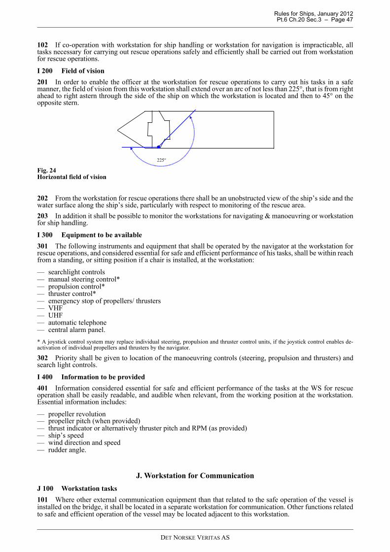
Rules for Ships, January 2012 Pt.6 Ch.20 Sec.3 – Page 47
102 If co-operation with workstation for ship handling or workstation for navigation is impracticable, alltasks necessary for carrying out rescue operations safely and efficiently shall be carried out from workstationfor rescue operations.
I 200 Field of vision
201 In order to enable the officer at the workstation for rescue operations to carry out his tasks in a safemanner, the field of vision from this workstation shall extend over an arc of not less than 225°, that is from rightahead to right astern through the side of the ship on which the workstation is located and then to 45° on theopposite stern.
Fig. 24Horizontal field of vision
202 From the workstation for rescue operations there shall be an unobstructed view of the ship’s side and thewater surface along the ship’s side, particularly with respect to monitoring of the rescue area.
203 In addition it shall be possible to monitor the workstations for navigating & manoeuvring or workstationfor ship handling.
I 300 Equipment to be available
301 The following instruments and equipment that shall be operated by the navigator at the workstation forrescue operations, and considered essential for safe and efficient performance of his tasks, shall be within reachfrom a standing, or sitting position if a chair is installed, at the workstation:
— searchlight controls— manual steering control*— propulsion control*— thruster control*— emergency stop of propellers/ thrusters— VHF— UHF— automatic telephone — central alarm panel.
* A joystick control system may replace individual steering, propulsion and thruster control units, if the joystick control enables de-activation of individual propellers and thrusters by the navigator.
302 Priority shall be given to location of the manoeuvring controls (steering, propulsion and thrusters) andsearch light controls.
I 400 Information to be provided
401 Information considered essential for safe and efficient performance of the tasks at the WS for rescueoperation shall be easily readable, and audible when relevant, from the working position at the workstation.Essential information includes:
— propeller revolution— propeller pitch (when provided)— thrust indicator or alternatively thruster pitch and RPM (as provided)— ship’s speed— wind direction and speed— rudder angle.
J. Workstation for Communication
J 100 Workstation tasks
101 Where other external communication equipment than that related to the safe operation of the vessel isinstalled on the bridge, it shall be located in a separate workstation for communication. Other functions relatedto safe and efficient operation of the vessel may be located adjacent to this workstation.
225°
DET NORSKE VERITAS AS
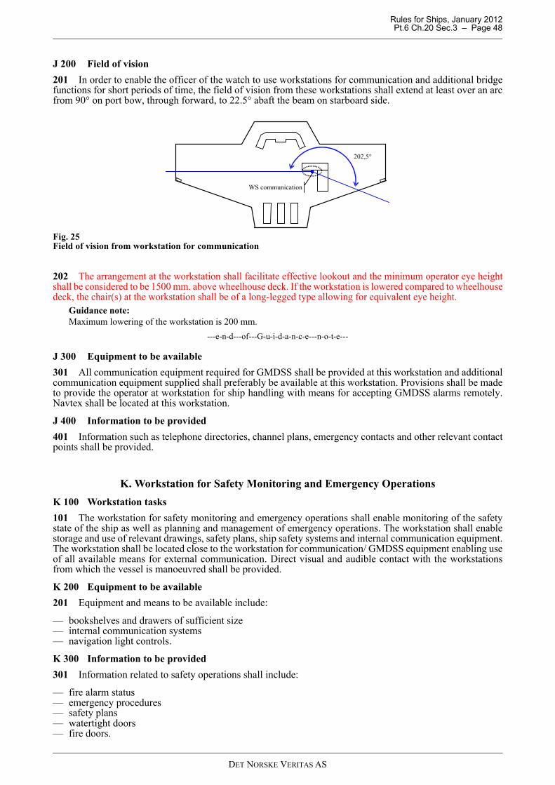
Rules for Ships, January 2012 Pt.6 Ch.20 Sec.3 – Page 48
J 200 Field of vision
201 In order to enable the officer of the watch to use workstations for communication and additional bridgefunctions for short periods of time, the field of vision from these workstations shall extend at least over an arcfrom 90° on port bow, through forward, to 22.5° abaft the beam on starboard side.
Fig. 25Field of vision from workstation for communication
202 The arrangement at the workstation shall facilitate effective lookout and the minimum operator eye heightshall be considered to be 1500 mm. above wheelhouse deck. If the workstation is lowered compared to wheelhousedeck, the chair(s) at the workstation shall be of a long-legged type allowing for equivalent eye height.
Guidance note:Maximum lowering of the workstation is 200 mm.
---e-n-d---of---G-u-i-d-a-n-c-e---n-o-t-e---
J 300 Equipment to be available
301 All communication equipment required for GMDSS shall be provided at this workstation and additionalcommunication equipment supplied shall preferably be available at this workstation. Provisions shall be madeto provide the operator at workstation for ship handling with means for accepting GMDSS alarms remotely.Navtex shall be located at this workstation.
J 400 Information to be provided
401 Information such as telephone directories, channel plans, emergency contacts and other relevant contactpoints shall be provided.
K. Workstation for Safety Monitoring and Emergency Operations
K 100 Workstation tasks
101 The workstation for safety monitoring and emergency operations shall enable monitoring of the safetystate of the ship as well as planning and management of emergency operations. The workstation shall enablestorage and use of relevant drawings, safety plans, ship safety systems and internal communication equipment.The workstation shall be located close to the workstation for communication/ GMDSS equipment enabling useof all available means for external communication. Direct visual and audible contact with the workstationsfrom which the vessel is manoeuvred shall be provided.
K 200 Equipment to be available
201 Equipment and means to be available include:
— bookshelves and drawers of sufficient size— internal communication systems— navigation light controls.
K 300 Information to be provided
301 Information related to safety operations shall include:
— fire alarm status— emergency procedures— safety plans— watertight doors— fire doors.
WS communication
202,5°
DET NORSKE VERITAS AS
Rules for Ships, January 2012 Pt.6 Ch.20 Sec.4 – Page 49
SECTION 4 BRIDGE EQUIPMENT
A. General Bridge Equipment Requirements
A 100 General requirements
101 All navigational and radio equipment installed shall comply with IMO Res. A.694(17) “Generalrequirements for ship borne radio equipment forming part of the GMDSS and for electronic navigational aids”.See also table E.2 in sec.1
Guidance note:Equipment should meet the requirements specified in IEC 60945.
---e-n-d---of---G-u-i-d-a-n-c-e---n-o-t-e---
102 All navigational equipment installed shall come with a certificate showing compliance with applicableIMO performance standards.
Guidance note:It is assumed that all navigational equipment to be installed for compliance with SOLAS and/or these rules comeswitha valid type approval certificate issued by a recognized certification authority.Any non-type-approved equipment is to be certified in accordance with the systematic of Pt.4 Sec.9, or MED moduleG if deemed applicable, for verification of compliance with appropriate international standards.
---e-n-d---of---G-u-i-d-a-n-c-e---n-o-t-e---
103 Equipment installed in addition to both SOLAS and the carriage requirement of this chapter shall complywith performance requirements not inferior to the rules or associated IMO performance standards as deemedapplicable.
Guidance note:Navigational equipment or systems that may affect steering or propulsion shall be certified in accordance with thesystematic of Pt.4 Ch.9 (or MED module G if deemed applicable) for verification of compliance with the rules andrelevant international standards unless the applicable function is already incorporated by the type approval certificate.Additional equipment installed should at least meet the requirements in IEC 60945 or DNV standard for certification 2.4
---e-n-d---of---G-u-i-d-a-n-c-e---n-o-t-e---
104 Additional bridge equipment, not required by the rules or international regulations that may have animpact on the safety of main functions shall comply with the applicable requirements of Pt.4 Ch.9.
Guidance note:Any non-type-approved equipment of this category is to be certified in accordance with the systematic of Pt.4 Sec.9or MED module G as deemed applicable. Note: Main functions are listed in Pt.1 Ch.1 Sec.1.
---e-n-d---of---G-u-i-d-a-n-c-e---n-o-t-e---
A 200 Location and installation of equipment
201 All instruments, panels, etc. shall be permanently mounted in consoles or at other appropriate places,taking into account both operational and environmental conditions. All other items, such as safety equipment,tools, lights, pencils etc. to be used by bridge personnel, shall be stored in designated places.
202 Any equipment, antennas and arrangement shall be installed in such a manner that the designedefficiency is not substantially impaired and, unless otherwise specified, follow the instructions andrecommendations detailed by the manufacturer.
203 Radar antennas shall be installed to enable detection of targets within 360°. Blind sectors occurring inone radar system shall, as far as practicable, not occur in the other system.
A 300 Interference
301 When placing equipment that shall be used in an exposed position, special care shall be taken to ensurethat the location does not impair the performance of the equipment.
302 The antennas for radars, position-fixing receivers and VHF communication systems shall be installed insuch a manner that interference is avoided and the designed efficiency is not substantially impaired.
Guidance note:VHF operating performance is highly dependent upon antenna location and height, and each antenna should beerected as high as possible, away from obstacles, wires, radar beams, etc. To avoid direct VHF-to-VHF radiation, theantennas should be vertically separated from each other at a distance not causing harmful interference.
DET NORSKE VERITAS AS
Rules for Ships, January 2012 Pt.6 Ch.20 Sec.4 – Page 50
The antennas for navigation receivers should be mounted in a location permitting a high degree of vertical orhorizontal polarised isolation against MF/HF transmitter antenna configuration. The GPS antenna should bepositioned outside the main lobe of INMARSAT-C, VHF and transmitting radar antennas.The S-band radar antenna should preferably be located at heights, which do not interfere with other shipboardobstructions. Nearby location of satellite communication antenna should not degrade the radar performance.
---e-n-d---of---G-u-i-d-a-n-c-e---n-o-t-e---
303 Transmitting and receiving antenna cables shall be widely separated.
A 400 Radiation hazard
401 Antenna units shall be located so as not to constitute a hazard to personnel working in the vicinity.Guidance note:The site of radar wave guides, satellite communication and HF transmitter feed lines should be safeguarded, so as toprotect personnel against open wave-guide radiation power and accidental contact with high voltages, by means ofisolating trunks or fences.
---e-n-d---of---G-u-i-d-a-n-c-e---n-o-t-e---
402 Satellite communication or radar antenna units are required to have a warning label, detailing safedistances, posted in the vicinity or on the equipment.
A 500 Vibration and shock isolation
501 Above deck equipment shall be sited so as to prevent the installation from being affected by vibration.
502 The antenna system and instrument installation shall withstand vibration to an extent that includes knownstandards for vibration environment according to the ship's construction, speed trim and the sea state.
503 Antenna systems including active elements shall be provided with a mount design configured towithstand potential shock damage.
A 600 Temperature protection
601 Instruments to be installed shall be located away from excessive heat sources, such as a heating vent orequipment heat exhaust.
602 Instruments to be fitted into a bridge instrument console shall be protected from excessive heat byconduction or, if necessary, by forced air flow.
Guidance note:Redundant systems should be installed in consoles where two or more systems are located and forced air flow isnecessary to ensure proper function of the equipment.
---e-n-d---of---G-u-i-d-a-n-c-e---n-o-t-e---
A 700 Interface to central alarm system
701 All equipment that gives audible alarms or audible warning signals shall be provided with two-waycommunication so that the central alarm system can be used for indication of alarms and warnings and theequipment shall be so arranged that the audible alarm and warnings on both the equipment and the central alarmsystem can be muted mutually.
Guidance note:IEC 61162-1 should be used as communication standard.
---e-n-d---of---G-u-i-d-a-n-c-e---n-o-t-e---
B. Equipment Requirements
B 100 Heading information system
101 Two separate and independent gyro compasses or other means having the capability to determine theship’s heading in relation to geographic (true) North shall be provided. At least one of the compasses shall bea gyro compass.
Guidance note:One of the gyro compasses can be replaced by a Transmitting heading devices type approved according to ISO 22090.
---e-n-d---of---G-u-i-d-a-n-c-e---n-o-t-e---
102 The system shall enable distribution of heading information to other systems.
DET NORSKE VERITAS AS
Rules for Ships, January 2012 Pt.6 Ch.20 Sec.4 – Page 51
103 The system shall identify which of the compass that is in use.
104 The Gyro compass system shall be provided with means for automatic correction of the errors caused byspeed and latitude.
105 Means shall be provided for comparing the two compasses and an alarm shall be given if the differencebetween the compasses exceeds the set value.
106 The heading information system and the distribution system shall be so arranged that no single failure inpower supply or distribution units may cause loss of heading information to consumers depending of headinginformation for function.
Guidance note:The following equipment is depending of heading information for normal function:
- heading/ bearing repeaters- heading control system/ track control system- joystick system- DP system- radar system- ECDIS.
---e-n-d---of---G-u-i-d-a-n-c-e---n-o-t-e---
B 200 Position system
201 Two separate and independent position fixing systems shall be provided. At least one of the positionreceivers shall be a GPS.
Guidance note:The independence of the two position-fixing systems may be achieved by separate antenna systems, display/ controlunits, power supply and digital interface output/ distribution units.
---e-n-d---of---G-u-i-d-a-n-c-e---n-o-t-e---
202 At least one of the position-fixing systems shall be capable of receiving and decoding of differential databroadcasted for navigational purposes by maritime radio beacons.
203 The position system and the distribution system shall be so arranged that no single failure in powersupply or distribution units may cause continuous loss of position information to consumers depending ofposition information for function.
Guidance note:The following equipment is depending of position information for function:
- track control system- DP system- chart radar system- ECDIS.
---e-n-d---of---G-u-i-d-a-n-c-e---n-o-t-e---
B 300 Steering and manoeuvring systems
301 The ship shall be equipped with means for manual and automatic steering of the ship.
302 The automatic steering system may be either heading control system, track control system, joystick orDynamic Positioning system.Seismic vesselsFor seismic vessels, a low speed (1 to 5 kn) track control is required to enable the ship to automatically followa pre-planned seismic route.The system shall at least give;
— cross track limit alarm (XTE)— new course change alarm— failure of sensors alarm.
303 Steering override control enabling instant take-over in case of failure in any of the automatic steeringsystems mentioned in 302 including the mode switch itself, shall be provided adjacent to the automatic steeringcontrol position.
304 Means for take command of all propulsion and all thrusters shall be provided at all workstations wheresteering or manoeuvring shall be carried out.
Guidance note:It shall be possible to take command at workstations where steering or manoeuvring is arranged for. The transfer of
DET NORSKE VERITAS AS
Rules for Ships, January 2012 Pt.6 Ch.20 Sec.4 – Page 52
command shall be arranged in a manner enabling the operator to either take command with the same settings as onthe previous workstation in command or with neutral settings.
---e-n-d---of---G-u-i-d-a-n-c-e---n-o-t-e---
305 It shall be a clear indication when workstation is in command.
306 Common mode selector switch controlling all propulsion and thrusters shall be provided as applicable ateach workstation.
Guidance note:The mode selector shall enable the operator to select mode of all propulsion and thrusters with one action. E.g. whenselecting Autopilot, Manual mode (transit or manoeuvring as applicable for any azimuth thrusters system), Joystickor DP with this selector switch, all the propellers and thrusters should be controlled in the selected mode.This switch shall be approved according to Pt.4 Ch.9.
---e-n-d---of---G-u-i-d-a-n-c-e---n-o-t-e---
307 Any back-up control of thrusters and propulsion shall have same user interface as the normal controls.
308 If any steering/propulsion means is provided not required by these rule, this shall be selectable andnecessary indicators for operation to be installed at this location.
B 400 Speed measuring system
401 A speed log measuring speed through water shall be provided.
402 NAUT-OSV (A): Sensor(s) for speed log shall have means for ice protection or be fitted with gate valvefor sensor replacing at sea without need for dry docking.
B 500 Depth measuring system
501 Echo sounder system for measuring the water depth under the keel shall be provided.
502 NAUT-OSV (A): Sensor(s) for echo sounder shall have means for ice protection or be fitted with gatevalve for sensor replacing at sea without need for dry docking.
B 600 Radar systems
601 Two separate and independent radar systems enabling inter-switching of the main components shall beprovided.
Guidance note:See A203 with respect to radar antenna installation.
---e-n-d---of---G-u-i-d-a-n-c-e---n-o-t-e---
602 One of the radars shall operate in X-band. The second radar shall operate in S-band or, where consideredappropriate based on operational aspects, in X-band.
603 Each individual radar system installed shall be equipped with a performance monitor.
604 If the radar inter-switching is so designed that one single failure may have an impact on both radars, thensufficient bypass facilities shall be provided and user instruction for by-passing shall be posted adjacent to theinter-switch.
605 Both radars shall have a daylight display with a minimum effective diameter of not less than 340 mm(320 mm for radar image).
606 Both radars shall be equipped with ARPA.
607 The radar at workstations for navigating & manoeuvring shall be interfaced to AIS for graphical displayof AIS reported targets in accordance with relevant IMO standards and guidelines.
608 The radar at workstations for navigating & manoeuvring shall be a Chart Radar with the ability to displayselected parts of SENC. This radar shall also be able to display the ship's position and the route used on theECDIS.
Guidance note:A Chart radar is a radar able to display selected parts of Electronic Navigational Chart (ENC) in accordance with IEC62388.
---e-n-d---of---G-u-i-d-a-n-c-e---n-o-t-e---
609 One of the radar systems shall be provided with additional slave display (for installation at workstationfor ship handling) with possibility for displaying selected parts of ENC in accordance with 608. This slavesystem shall have means for controlling the range and adjust tuning, anti sea clutter, anti rain clutter and gain.
DET NORSKE VERITAS AS
Rules for Ships, January 2012 Pt.6 Ch.20 Sec.4 – Page 53
Guidance note:This requirement is not applicable for pure platform supply vessels.This requirement is related to NAUT-OSV as specified for workstation for ship handling in Sec.2. Alternative meansto chart radar, can be slave radar + slave ECDIS.Radar display shall have a daylight display with a minimum effective diameter of not less than 250 mm.
---e-n-d---of---G-u-i-d-a-n-c-e---n-o-t-e---
610 Seismic vessels: The radar installation shall provide coverage of the seismic tow without blind sectors.This may be achieved by the required navigation radar installation or by installing additional radar for suchpurposes.
B 700 ECDIS
701 Electronic chart display and information system (ECDIS) shall be provided.
702 Electronic back-up for ECDIS shall be provided and shall be independent of ECDIS.Guidance note:Conning display, a second chart radar or a second ECDIS may serve the ECDIS back-up function when located atworkstation monitoring.See IEC 61174 Annex G for further details about ECDIS Back-up.
---e-n-d---of---G-u-i-d-a-n-c-e---n-o-t-e---
703 ECDIS shall be able to transfer route information to chart radar for enabling display of active route on thechart radar.
Guidance note:Route information shall be in accordance with IEC 61162 and shall be possible to send directly to chart radar withoutuse of external media such as diskettes.
---e-n-d---of---G-u-i-d-a-n-c-e---n-o-t-e---
B 800 AIS MKD
801 The ECDIS and/or the radar installed at the workstation for navigation & manoeuvring shall support theAIS MKD (possibility to operate the AIS from the workstation).
B 900 Bridge Navigational Watch Alarm System (BNWAS)
901 The ship's wheelhouse shall be equipped with a surveillance system continuously monitoring thepresence of an alert OOW. The BNWAS shall maintain supervision of the wheelhouse to ensure thenavigational watch being attended when the ship is underway at sea. The BNWAS system shall be typeapproved according to requirements in IMO Performance standard for Bridge navigational Watch AlarmSystem, an in addition comply with the requirements in these rules.
Guidance note:The surveillance system should be able to detect human activity (motion).
---e-n-d---of---G-u-i-d-a-n-c-e---n-o-t-e---
902 Surveillance of the navigational watchMeans for activating the BNWAS reset function by automatic detection of human motion shall be provided atworkstation for navigating & manoeuvring, workstation for monitoring and workstation for conning. If motiondetection is provided at workstation for offshore operation and workstation for offshore support it shall bepossible to select/deselect the bridge area in use (I.E select between fore and aft bridge).
Guidance note:The most common method by which motion can be automatically detected employs use of sensors processing infraredimages, microwave reflections, ultra sonic sound reflections or image recognitions systems.Sensors may use one or several of these technologies in combination. Sensors approved for alarms systems forintrusion and hold-up systems according to EN 50131 may be used provided that the BNWAS can comply tofollowing functional requirements
- Timer is reset if a forearm is moving 0.5 to 1 m/s at the working position. - Failure or tamper of the motion sensor is deactivating the timer reset function due to automatic motion detection. - Timer are not reset due to shifting sunlight, moving objects or surfaces as expected onboard a moving ship. - Potential masking of sensor detection area to obtain detection in areas providing proper outlook only is done
internally in the sensor.
---e-n-d---of---G-u-i-d-a-n-c-e---n-o-t-e---
903 It shall be possible for the OOW to select individually any of the navigation officers or the captain asbeing the assigned back-up officer for receiving the second stage remote audible alarm. Whenever captain is
DET NORSKE VERITAS AS
Rules for Ships, January 2012 Pt.6 Ch.20 Sec.4 – Page 54
not selected as the assigned back-up officer, the captain cabin and office shall be included in the list of locationsreceiving the third stage remote audible alarm.
— Captains cabin and office — officers' office— officers' mess— officers' day room— cargo control room (if provided)— gymnasium (if provided)— sky lobby (if provided)— other public rooms and areas (if provided).
Guidance note:To extend the accessible area for back-up personnel the alarms may additionally be transferred by means of a wirelesssystem to call the assigned back-up navigator on the condition that it is possible for the assigned person to reach thebridge within 2 minutes.
---e-n-d---of---G-u-i-d-a-n-c-e---n-o-t-e---
B 1000 Alarm Management System (AMS)
1001 Alarm Transfer:The bridge navigational watch alarm system shall be inter-connected with the alarm management system foractivation of the BNWAS sequence of indications and alarms when Category A alarms are not acknowledgedor silenced in due time. Activation of the reset function during these sequences shall cancel the alarm transferbut shall not silence or acknowledge the relevant Category A alarm on the AMS.
1002 Integration of equipment:An alarm management system (AMS) enabling all alarms generated by individual navigational equipment andother equipment generating alarms in wheelhouse to be centralised in one common AMS display. This panel shallbe located at the required workstations enabling easy identification of the source and cause of the alarms and rapidacknowledgement of category B alarms and cancellation of audible category A alarm signals shall be provided.
Guidance note:Conning display may be used as AMS display.The audible level of alarms and warnings should be 75 dB(A). The minimum equipment to be integrated by the AMSshould include:
---e-n-d---of---G-u-i-d-a-n-c-e---n-o-t-e---
1003 The number of alarms shall be kept as low as possible by providing indications for information of lowerimportance not requiring any action.
Guidance note:References are made to IMO resolutions MSC.86(70) Annex 3, 4.3.5 and A.1021(26).
---e-n-d---of---G-u-i-d-a-n-c-e---n-o-t-e---
1004 An acknowledgement of a category B alarm on either the AMS or the individual equipment raising thealarm shall acknowledge the alarm on both the individual equipment and the AMS.
Guidance note:When an alarm is acknowledged, the audible alarm signal shall be silenced and the visual alarm presentations shallbe changed from red/ flashing to red/ steady on both the individual equipment and on the AMS.
---e-n-d---of---G-u-i-d-a-n-c-e---n-o-t-e---
1005 A silencing of a category A alarm on either the AMS or the individual equipment raising the alarm shallsilence the audible alarm signal on both the individual equipment and the AMS.
Guidance note:When the audible alarm signal is silenced on the AMS, the visual alarm presentation shall remain red/ flashing onboth the individual equipment and on the AMS.
- track control system (if relevant) - EPFSs Additional equipment may comprise:- heading control system - speed logs - UMS alarm panel- heading information systems - echo sounder - steering gear alarm panel- radars/ARPAs - bridge navigational watch alarm system - navigation light alarm panel- ECDISs - GMDSS - VDR alarm panel, etc.
- Other sources giving alarms and warnings in wheelhouse
DET NORSKE VERITAS AS
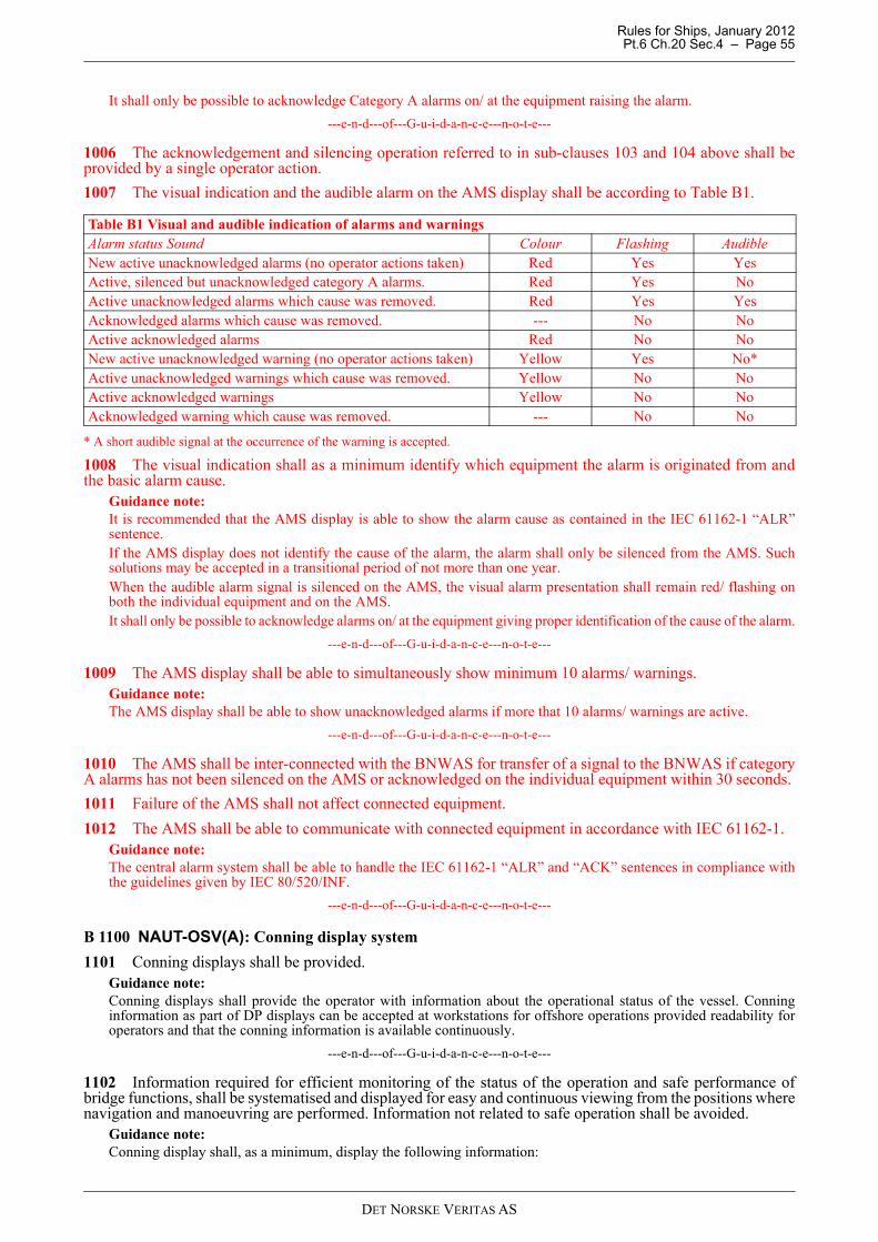
Rules for Ships, January 2012 Pt.6 Ch.20 Sec.4 – Page 55
It shall only be possible to acknowledge Category A alarms on/ at the equipment raising the alarm.
---e-n-d---of---G-u-i-d-a-n-c-e---n-o-t-e---
1006 The acknowledgement and silencing operation referred to in sub-clauses 103 and 104 above shall beprovided by a single operator action.
1007 The visual indication and the audible alarm on the AMS display shall be according to Table B1.
* A short audible signal at the occurrence of the warning is accepted.
1008 The visual indication shall as a minimum identify which equipment the alarm is originated from andthe basic alarm cause.
Guidance note:It is recommended that the AMS display is able to show the alarm cause as contained in the IEC 61162-1 “ALR”sentence.If the AMS display does not identify the cause of the alarm, the alarm shall only be silenced from the AMS. Suchsolutions may be accepted in a transitional period of not more than one year.When the audible alarm signal is silenced on the AMS, the visual alarm presentation shall remain red/ flashing onboth the individual equipment and on the AMS.It shall only be possible to acknowledge alarms on/ at the equipment giving proper identification of the cause of the alarm.
---e-n-d---of---G-u-i-d-a-n-c-e---n-o-t-e---
1009 The AMS display shall be able to simultaneously show minimum 10 alarms/ warnings.Guidance note:The AMS display shall be able to show unacknowledged alarms if more that 10 alarms/ warnings are active.
---e-n-d---of---G-u-i-d-a-n-c-e---n-o-t-e---
1010 The AMS shall be inter-connected with the BNWAS for transfer of a signal to the BNWAS if categoryA alarms has not been silenced on the AMS or acknowledged on the individual equipment within 30 seconds.
1011 Failure of the AMS shall not affect connected equipment.
1012 The AMS shall be able to communicate with connected equipment in accordance with IEC 61162-1.Guidance note:The central alarm system shall be able to handle the IEC 61162-1 “ALR” and “ACK” sentences in compliance withthe guidelines given by IEC 80/520/INF.
---e-n-d---of---G-u-i-d-a-n-c-e---n-o-t-e---
B 1100 NAUT-OSV(A): Conning display system
1101 Conning displays shall be provided.Guidance note:Conning displays shall provide the operator with information about the operational status of the vessel. Conninginformation as part of DP displays can be accepted at workstations for offshore operations provided readability foroperators and that the conning information is available continuously.
---e-n-d---of---G-u-i-d-a-n-c-e---n-o-t-e---
1102 Information required for efficient monitoring of the status of the operation and safe performance ofbridge functions, shall be systematised and displayed for easy and continuous viewing from the positions wherenavigation and manoeuvring are performed. Information not related to safe operation shall be avoided.
Guidance note:Conning display shall, as a minimum, display the following information:
Table B1 Visual and audible indication of alarms and warningsAlarm status Sound Colour Flashing AudibleNew active unacknowledged alarms (no operator actions taken) Red Yes YesActive, silenced but unacknowledged category A alarms. Red Yes NoActive unacknowledged alarms which cause was removed. Red Yes YesAcknowledged alarms which cause was removed. --- No NoActive acknowledged alarms Red No NoNew active unacknowledged warning (no operator actions taken) Yellow Yes No* Active unacknowledged warnings which cause was removed. Yellow No NoActive acknowledged warnings Yellow No NoAcknowledged warning which cause was removed. --- No No
DET NORSKE VERITAS AS
Rules for Ships, January 2012 Pt.6 Ch.20 Sec.4 – Page 56
- steering mode (manual, autopilot, DP, joystick, transit/ docking mode, as applicable.)- essential information from the power management system or equivalent information- heading- speed- rudder angle- water depth- thruster status indications- individual thruster indications or alternatively individual thruster pitch and RPM (as provided)- propulsion status indication- propeller revolutions- pitch indication, when relevant- winch load (and available force), wire length and wire speed, when relevant- wind indication.If the vessel is equipped with track control system, see IMO performance standard for additional information.
---e-n-d---of---G-u-i-d-a-n-c-e---n-o-t-e---
1103 To enable easy viewing, the conning information display shall utilise graphical display technique andlocate relevant sensor input data appropriately around and on a symbol illustrating own ship.
1104 The orientation of the conning picture shall be consistent with the ship orientation as seen from theoperator position.
1105 Parts of the display area might be dedicated to user interface for central alarm system.
1106 Provision of independent indicators for equipment (typically rudder, propulsion, thrusters) may beomitted when the required information is provided in mutually redundant conning displays at the requiredworkstations. See DNV Rules Pt.4 Ch.9.
Guidance note:Rudder, pitch and RPM indicators are required to be type approved as such and use of conning display to replace suchindicators will imply that the conning need to be approved for this. For vessels applicable for EC MED this implieswheel marking.
---e-n-d---of---G-u-i-d-a-n-c-e---n-o-t-e---
B 1200 Internal communication equipment
1201 Automatic telephone system (applicable to NAUT-OSV)
a) an automatic telephone system shall be installed and shall provide two-way voice communication betweenthe bridge and:
— all officers cabins— all deck hand cabins— all public rooms— all normal working spaces and— all emergency working positions.
b) The telephone network shall be designed with a minimum capacity of four simultaneous calls. c) The wheelhouse shall be fitted with at least two independent telephone extensions. d) The telephone extensions in the wheelhouse and engine control room shall have priority function over any
other extension. e) Incoming calls on adjacent telephones shall be distinguishable by lights and/or different ring tones. f) The automatic telephone system shall be supplied by mains and emergency sources of power.
B 1300 External communication system
1301 At least two fixed independent VHF systems shall be provided for simultaneously use from relevantworkstations.
1302 NAUT-OSV(A): At least two fixed independent UHF systems shall be provided for simultaneously usefrom relevant workstations.
B 1400 CCTV systems
1401 CCTV system shall provide the operator with true colour pictures of relevant areas for compensatinglack of direct visual viewing.
1402 The monitor size shall be adequate for easy viewing from the operator’s position.Guidance note:Picture size should be: The minimum length of the shortest side of the picture should be 1/9 of the reading distance
DET NORSKE VERITAS AS
Rules for Ships, January 2012 Pt.6 Ch.20 Sec.4 – Page 57
in cm. i.e. if the distance from the operator to the monitor is 3 meters, the monitor’s shortest side should be 33 cm(33 × 33 cm display if square and 33 × 44 cm if 4:3 format).
---e-n-d---of---G-u-i-d-a-n-c-e---n-o-t-e---
1403 NAUT-OSV(A): All cameras which are required by these rules and which are mounted on open deckexposed to sea water mist, shall be equipped with fresh water lens wash and wiperss for cleaning.
B 1500 Weather information system
1501 The ship shall be equipped with an anemometer providing information about wind speed and direction.
1502 Ships engaged in world wide trade shall be equipped with a shipboard weather station providinginformation about air temperature, air humidity and barometric pressure.
1503 Ships shall be equipped with a weather information systemGuidance note:A marine computer including a software application for receipt and displaying of regular weather forecasts, or aweather fax may be acceptable.Ships not engaged in world wide trade may, if found unreasonable, be exempted from this requirement provided analternative suitable system or method for receiving relevant weather information is provided.
---e-n-d---of---G-u-i-d-a-n-c-e---n-o-t-e---
B 1600 NAUT-OSV(A): Search lights
1601 At least 2 remotely controlled searchlights shall be provided to illuminate areas of interest in ahorizontal sector of 360° around the vessel with vertical adjustment allowing view of the sea close to the ship’sside and up to 35° above the horizon.
C. Electrical Power Supply
C 100 Main electrical power supply
101 The power supply requirements in this chapter are additional to those given in Pt.4 Ch.8
102 The power supplies to the distribution panels shall be arranged with automatic changeover facilitiesbetween main and emergency power sources. Failure of one of the power supplies to the distribution panelsshall initiate an alarm (audible and visual signal).
C 200 Stand-by power supply
201 Following equipment shall be provided with a transitional source of power with a capacity to keep theequipment running during a black-out period of at least 10 minutes.
— one radar with ARPA (including the antenna) at Workstations for navigating & manoeuvring— position-fixing system – GPS or GLONASS— ECDIS at Workstations for navigating & manoeuvring.
202 At least one gyro compass shall be provided with a transitional source of power with a capacity to keepit running for 30 minutes.
203 The UPSes used to supply bridge equipment shall have automatic bypass functionality.
204 Appropriate means for bypassing the UPS manually, in case of failure in the automatic bypass, shall beprovided.
205 Failure of the UPS shall initiate an alarm (audible and visual signal).
DET NORSKE VERITAS AS
Rules for Ships, January 2012 Pt.6 Ch.20 Sec.5 – Page 58
SECTION 5 ERGONOMICS AND HUMAN-MACHINE INTERFACE
A. Human - Machine Interface
A 100 General
101 All equipment and indicators shall be designed with due regard to the human operator. Controls andindicators shall be in accordance with relevant Rules in Pt.4 Ch.9 and be so constructed that they can beefficiently operated by suitably qualified personnel.
102 Human factor principles shall be an integrated part of engineering from early design phase forequipment, controls and indicators.
103 During all operations, it shall be possible to observe the ship’s status, the state of systems in use and otheressential data.
104 Operation of controls and equipment shall either give the user feedback of the action through the controlitself or through an indicator/ display adjacent to or in the natural vicinity of where the operation takes place.
105 Information and controls shall be arranged in logical groups, and shall be co-ordinated with the geometryof the vessel, when this is relevant.
B. Controls
B 100 Control devices
101 The number of operational controls, their design and manner of function, location, arrangement and sizeshall provide for simple, quick and effective operation.
102 Controls shall be arranged in functional groups.
103 Revolving controls for changing values up or down shall be designed so that clockwise turn increasevalue and vice versa. If push buttons are used, the push button at right shall increase value and vice versa.
104 Controls shall give clear feedback when passing stepwise positions or neutral positions.Guidance note:Levers should give noticeable resistance when passing neutral position. Switches should give clear feedback when innew position.
---e-n-d---of---G-u-i-d-a-n-c-e---n-o-t-e---
105 Controls for thrusters and propulsion shall use consistent user interface.
106 For main control devices regulating the ship’s heading during normal navigation in transit mode, aclockwise or starboard movement shall turn the ship’s bow towards starboard and vice versa. For thrustersbeing used during manoeuvring, the control device movement shall correspond to the resulting thrust force.
Guidance note:When azimuth thrusters are main propulsion system, means should be provided for control of these in transit mode asdescribed above and this tiller, lever or joystick should be clearly distinguish in shape/ form from the main azimuththruster control. This means may not necessarily control the thruster(s) more than +/- 35°.
---e-n-d---of---G-u-i-d-a-n-c-e---n-o-t-e---
B 200 Operation of controls
201 All operational controls shall permit normal adjustments to be easily performed and shall be arranged ina manner which minimises the possibility of inadvertent operation. Controls not required for normal operationshall not be readily accessible.
202 The operation of a control shall not obscure the related indicator where observation of the indicator isnecessary for making the adjustment.
203 In all operations, there shall be a clearly marked or consistent simple action to recover from a mistakenchoice or to leave an unwanted state. It shall be possible for the user to start, interrupt, resume and end anoperation. Incomplete or interrupted manual inputs shall not inhibit the operation of the equipment.
204 Controls shall be designed and arranged to avoid inadvertent operation. If controls are designed withspecial operation (e.g. double click or long time press) they shall be clearly distinct from other similar controlswith similar design.
DET NORSKE VERITAS AS
Rules for Ships, January 2012 Pt.6 Ch.20 Sec.5 – Page 59
B 300 Identification of controls
301 All operational controls and indicators shall be easy to identify and to read from the position at whichthe equipment is normally operated. The controls and indicators shall be identified in English and marineterminology shall be used.
Guidance note:Symbols as specified in IEC 60417 or in the other relevant standards may be used in addition to the identification inEnglish.
---e-n-d---of---G-u-i-d-a-n-c-e---n-o-t-e---
C. Presentation of Information
C 100 General
101 Displays and indicators shall present the simplest information consistent with their function, informationirrelevant to the task shall not be displayed, and extraneous text and graphics shall not be present.
102 During all operations, the system’s state shall be observable with essential data displayed.
103 All information required by the user to perform an operation shall be available on the current display.
104 The mode of the systems in use shall be displayed.
105 It shall be possible at any step of a screen supported operation to return to the original display status priorto initiation of operations by single operator action.
106 Feedback timing shall be consistent with the task requirements. There shall be clear feedback from anyaction within a short time. Where a perceptible delay in response occurs, visible indication shall be given.
C 200 Menus
201 Menus shall be grouped according to the task.
202 Items of any kind which appear the same shall behave consistently.
203 The user shall not have to remember information when moving from one part of a menu to another.
204 Frequently used operations shall be available in the upper menu level, on dedicated software or hardwarebuttons.
205 Main display shall be available with a single operator action.
C 300 Text/ symbols
301 Displayed text shall be clearly legible to the user and easy to understand.
302 Simple natural language shall be used wherever possible. The equipment shall employ marineterminology.
303 Where additional on-line help is available it shall be in task dependent form, easy to search and list thesteps to be carried out.
C 400 Illumination
401 All information shall be presented on a background of high contrast, emitting as little light as possible atnight, so that it does not degrade the night vision of the officer on watch.
Guidance note:All ship’s bridge instruments should show a light text on a dark non-reflecting background at night. The contrastshould be within 1:3 and 1:10.
---e-n-d---of---G-u-i-d-a-n-c-e---n-o-t-e---
402 Each instrument shall be fitted with an individual light adjustment. In addition, groups of instrumentsnormally in use simultaneously may be equipped with common light adjustment.
403 Warning and alarm indicators shall be designed to show no light in normal position that is indication ofa safe situation. Means shall be provided to test the lamps.
Guidance note:Alarm indicator lights should be equipped with red lights of wavelength 620 nanometres or higher.
---e-n-d---of---G-u-i-d-a-n-c-e---n-o-t-e---
404 Colour coding of functions and signals shall be in accordance with international standards.
DET NORSKE VERITAS AS
Rules for Ships, January 2012 Pt.6 Ch.20 Sec.5 – Page 60
Guidance note:ISO 2412 “Shipbuilding: Colours of indicator lights”, Table A4 lists recommended colour codes for system functions.
---e-n-d---of---G-u-i-d-a-n-c-e---n-o-t-e---
405 Means for adjusting the display and operating panel brightness shall be provided. Operator panels andother functional controls shall be illuminated to ensure ease of operation in the dark. Night vision shall besecured by considering the following:
— warning and alarm indicators shall show no light in normal position (indication of a safe situation). Allinstruments shall be fitted with permanent internal or external light source to ensure that all necessaryinformation is visible at all times
— means shall be provided to avoid light and colour changes upon, e.g. start-up and mode changes, which mayaffect night vision
— all information shall be presented on a background of high contrast, emitting as little light as possible bynight.
D. Readability of Information
D 100 General
101 Instruments or displays providing visual information to more than one person shall be located for easyviewing by all users concurrently. If this is not possible, the instruments or displays shall be duplicated.
102 The operation of a control shall not obscure indicator elements where observation of these elements isnecessary for adjustments to be made.
D 200 Location
201 The information presented shall be clearly visible to the user and permit easy and accurate reading at apracticable distance in the light conditions normally experienced at the location of the workstation by day andby night.
202 Instruments meant to be operated or fitted in connection with controls shall be readable from a distanceof at least 1 000 mm. All other instruments shall be readable from a distance of at least 2 000 mm.
Guidance note:Character height in mm should be not less than 3.5 times the reading distance in m. Letter width should be 0.7 timesthe letter height, e.g.:
Character height for reading distance 2 m: 2 × 3.5 = 7 mmCharacter width for letter height 7 mm: 7 × 0.7 = 4.9, i.e. 5 mmResulting minimum character size: 7 mm × 5 mm.
---e-n-d---of---G-u-i-d-a-n-c-e---n-o-t-e---
203 Each instrument shall be placed with its face normal to the navigator's line of sight, or to the mean valueif the navigator's line of sight varies through an angle.
204 Instrument letter type shall be of simple, clear-cut design.Guidance note:
a) Internationally used and recommended letter type is Helvetica medium. However, light-emitting diode textmatrices are acceptable.
b) In descriptive text, lower case letters are easier to read than capitals.
---e-n-d---of---G-u-i-d-a-n-c-e---n-o-t-e---
DET NORSKE VERITAS AS
Rules for Ships, January 2012 Pt.6 Ch.20 Sec.6 – Page 61
SECTION 6 BRIDGE EQUIPMENT TESTS
A. On Board Testing of Bridge Equipment
A 100 General
101 After installation of equipment in ships requesting class notation NAUT-OSV(T) or NAUT-OSV(A),on-board testing of the equipment shall be performed in order to ascertain that the equipment, as installed,operates satisfactorily.
102 It should be noted that reliable figures for all aspects of equipment performance or accuracy cannot beestablished by the on board testing required for classification. Therefore, to ensure that equipment performanceis in accordance with specifications, ship owners and ship yards are advised to choose equipment that is typeapproved.
A 200 Test program
201 A detailed program for the on board testing of this equipment shall be submitted for approval at theearliest possible stage before sea trials.
202 The test program shall be in accordance with the requirements for on board testing given in this section,and shall specify in detail the tests to be performed for each type of equipment.
A 300 General requirements for the testing of all types of bridge equipment
301 Prior to testing, all equipment shall be checked and calibrated by a representative of the manufacturer orthe equipment supplier.
302 Prior to testing, all equipment, etc., necessary for the observation and recording of test results, shall bemade available. Charts for the area where the sea trials shall take place must be available. Large-scale chartsfor the area where the ship is berthed must be available.
303 Equipment and systems that shall be subject to the tests are required to ascertain that all controls,indicators, displays, etc. operate in accordance with their specifications and meet the rule requirements.
304 Failure conditions shall be simulated on equipment and systems.
305 Power supply alarms, UPS capacity/ battery discharge test and bypass functionality shall be tested.
306 A demonstration including start-up of the individual systems and changeover from normal conditions tofailure conditions shall be carried out.
307 Failure conditions of computer system(s), especially power failure, shall be simulated as realistically aspossible. Manual re-starts and, if relevant, automatic re-start and automatic back-up shall be tested. Successivepower breaks shall be simulated.
308 If computer system(s) is used to carry out secondary functions, testing of the system shall be carried outwith all primary functions in operation and with maximum load from both primary and secondary functions.
309 Tests, additional to the approved test program, may be required carried out by the surveyor.
A 400 Heading measuring and information system
401 The settle point error of the master compass(es) and the alignment with the ship's centre line shall bedetermined using e.g. the bearing (direction) of the quay at which the ship is berthed.
402 The bearing repeaters' alignment with the ship's centre line shall be checked. A bearing dioptre must beavailable.
403 The divergence between No. 1 master compass and the gyro repeaters shall be checked. After switchingto No. 2 master compass, the divergence with the gyro repeaters shall be checked again.
404 The monitoring functions of the compass system shall be tested.
405 The means for correcting errors caused by speed and latitude shall be tested.
A 500 Steering System
501 Proper functioning, including ergonomics/ HMI and effect of failures, of the following shall be tested:
— take command functionality at workstations— steering mode selector(s) in all modes at all workstations— manual steering devices— joystick (if installed).
DET NORSKE VERITAS AS
Rules for Ships, January 2012 Pt.6 Ch.20 Sec.6 – Page 62
A 600 Automatic steering system
601 The heading-keeping/ track keeping performance of the autopilot/ Track control system shall be testedat full sea speed. Adaptive autopilots shall also be tested at reduced speed.
602 The performance of the autopilot shall be checked for a change in heading of 10° and 60° to both sides.The overshoot angle shall be observed.
603 The off heading alarm/ off track alarm shall be tested.
604 The rate-of-turn or radius function shall be tested.
605 Change of operational steering mode shall be tested.
606 The override function shall be tested in all steering modes.
607 The lowspeed track control system shall be tested at speed for seismic operations (typically 2 to 5 knots).
A 700 Rudder indicator(s)
701 The rudder indicator(s) on the bridge shall be checked against the indicator on the rudderstock.
A 800 Speed log
801 The speed log shall be checked for accuracy and, if necessary, calibrated.
A 900 Echo sounder
901 Function testing of the echo sounder shall be carried out. Depth shall be measured at a fixed position forexact comparison of accuracy and at full speed ahead on all range scales available.
902 The depth warning or alarm shall be tested.
A 1000 Radar system
1001 Function testing of the radar shall be carried out. The various ranges, presentation modes and the basicradar functions shall be tested.
1002 Testing of the Chart radar functionality shall be performed to verify consistent reference position,orientation and scale. Official ENC data to be loaded before testing.
1003 The accuracy of bearing of the radars shall be tested by the reading of at least 4 fixed positions on thedisplay at a known position of the ship.
1004 The accuracy of range measurement shall be tested by measuring the distance to at least 2 fixedpositions at each range while the ship is in a known position.
1005 The heading marker shall be checked against a visible target dead ahead and adjusted if necessary.
1006 Failure mode by disconnecting a fuse shall be observed.
1007 Inter-switching facilities, including bypass function, shall be tested.
1008 Performance monitors shall be checked.
1009 Self-check programs shall be run.
1010 Indication on the display of the bearing and distance to the object, as well as the heading of own ship,shall be tested.
1011 When manoeuvring the ship, the normal functioning of the ARPA, including automatic acquisition,shall be checked.
1012 The trial manoeuvre function of the ARPA shall be tested.
1013 Tests shall be carried out to verify that the system gives warning when the limits of CPA and TCPA areexceeded and that a warning is given when the object enters the guard ring.
1014 Input from speed sensors shall be checked.
A 1100 Sound reception system
1101 The sound reception system shall be tested by measuring and comparing the sound level outside andinside the wheelhouse. The directional indication shall be tested.
Guidance note:The fundamental frequency of the sound signal used in testing the system should be within the range 70 to 820 Hz.
---e-n-d---of---G-u-i-d-a-n-c-e---n-o-t-e---
DET NORSKE VERITAS AS
Rules for Ships, January 2012 Pt.6 Ch.20 Sec.6 – Page 63
A 1200 Electronic position-fixing systems
1201 All electronic position-fixing fitted system(s) shall be function-tested.
1202 The accuracy of the electronic position-fixing system(s) shall be checked.
1203 Interference from transmitting systems such as VHF’s, radars, active VHF TV antennas shall be tested.
A 1300 Automatic Identification System (AIS)
1301 The AIS shall be function tested to verify proper interconnection to own ship navigational sensors.
1302 The correct setting of static information (Ship Name, Call sign, MMSI number etc.) shall be verified.
A 1400 Electronic chart display and information system (ECDIS)
1401 The accuracy, functionality and the alarm or warning functions of the ECDIS shall be tested.Performance of automatic functions, such as positioning of the ship by means of dead reckoning and GPS,plotting of the track and updating of the data base, shall be included in the tests together with the followingoperations:
— route planning— altering of the route while underway— positioning by bearings and ranges— manual adjustment of the ship’s position on the screen— scale changes and zooming functions.
Official ENC data to be loaded before testing.
1402 The ECDIS back-up system shall be tested for proper interconnection with the primary ECDIS. Routeplanning, route monitoring, including alarms, shall be tested.
1403 Self-check programs shall be run.
A 1500 Conning display
1501 The performance of conning display(s) function shall be tested, including the accuracy and readabilityof the data displayed.
A 1600 Propulsion System
1601 Proper functioning, including ergonomics/ HMI and effect of failures, of the propulsion system shall betested.
A 1700 Communication systems
1701 The communication systems shall be tested for proper function.
1702 The automatic telephone system and internal communication system between workstations shall betested.
1703 The priority function for the telephones in the wheelhouse and engine control room over the otherextensions shall be tested.
1704 VHF systems shall be tested.
1705 UHF systems shall be tested.
A 1800 Central alarm system
1801 The alarm announcement function of the central alarm system shall be tested for verifying correct alarmsyntax, audibility level and acknowledgement function.
1802 It shall be tested that all equipment providing alarms on the bridge is connected to the central alarmsystem and provides two-way communication for silencing of audible alarms in accordance with approveddrawings and schematics.
A 1900 Watch monitoring and alarm transfer system
1901 The off-track monitoring system shall be tested. It shall be checked that the off-track alarm istransferred to the places specified if it is not acknowledged within the pre-set limit.
1902 The traffic-monitoring function of the ARPA (guard zones and CPA or TCPA) shall be tested. It shallbe checked that the warning is transferred if not acknowledged within the pre-set limit.
1903 The off- heading monitoring system shall be tested. It shall be checked that the off-heading alarm fromthe heading control system and the compass deviation alarm from the compass monitor is transferred to theplaces specified if it is not acknowledged within the pre-set limit.
DET NORSKE VERITAS AS
Rules for Ships, January 2012 Pt.6 Ch.20 Sec.6 – Page 64
1904 It shall be checked that the wheel over point approach alarm from the ECDIS is transferred to the placesspecified if it is not acknowledged within the pre-set limit.
1905 The watch monitoring (dead-man) alarm system shall be tested and the transfer of alarms checked.
A 2000 CCTV system
2001 The CCTV system shall be tested for verifying appropriate reproduction on the indoor monitor,including colour correctness, brightness, dimming facilities (if the monitor can degrade the OOW’s nightvision) and display size. It shall further be verified that the picture is free of flickering.
2002 Means for cleaning the camera lens to be tested for cameras located in areas exposed to salt-mist.
A 2100 Window clear view devices
2101 The means for maintaining clear view through bridge windows shall be tested.
DET NORSKE VERITAS AS