Embed Size (px)
Citation preview

AUTOCAD®
CIVIL 3D®
2008
NEW ZZEALAND COUNTRY KIT
AutoCAD Civil 3D 2008 New Zealand Country Kit
2
1 TABLE OF CONTENTS
2 Purpose of this document: .............................................................................................................. 4
3 Drafting and Plans Production Settings ........................................................................................... 5
3.1 Sheet Creation......................................................................................................................... 5
3.2 Drafting and Labeling .............................................................................................................. 5
3.3 Settings.................................................................................................................................... 5
3.4 Reports .................................................................................................................................... 5
4 General Enhancements and Maintenance ...................................................................................... 6
5 OBJECT LAYERS, OBJECT COMPONENT DISPLAY LAYERS, COLOURS, LINETYPES AND LAYER
MANAGER ................................................................................................................................................. 7
6 GENERAL .......................................................................................................................................... 9
7 POINTS ........................................................................................................................................... 11
8 SURFACES ....................................................................................................................................... 15
9 PARCEL ........................................................................................................................................... 17
10 GRADING ........................................................................................................................................ 22
11 ALIGNMENT ................................................................................................................................... 23
12 PROFILE .......................................................................................................................................... 26
13 PROFILE VIEW ................................................................................................................................ 28
14 SAMPLE LINES ................................................................................................................................ 32
15 SECTIONS ....................................................................................................................................... 33
16 SECTION VIEWS .............................................................................................................................. 34
17 Pipe Rules ....................................................................................................................................... 36
18 PIPE NETWORK .............................................................................................................................. 37
19 PIPE ................................................................................................................................................ 38
20 STRUCTURE .................................................................................................................................... 39
21 Corridor Design Standards ............................................................................................................. 40
22 CORRIDOR ...................................................................................................................................... 41
23 ASSEMBLY ...................................................................................................................................... 42
24 SUBASSEMBLY ................................................................................................................................ 43
AutoCAD Civil 3D 2008 New Zealand Country Kit
3
25 QUANTITY TAKEOFF ....................................................................................................................... 44
26 Quantities Report Style Sheets ...................................................................................................... 45
27 SURVEY .......................................................................................................................................... 46
28 VIEW FRAME GROUP ..................................................................................................................... 47
29 VIEW FRAME .................................................................................................................................. 48
30 MATCH LINE ................................................................................................................................... 49

AutoCAD Civil 3D 2008 New Zealand Country Kit
4
2 PURPOSE OF THIS DOCUMENT:
This document defines the content to be delivered as part of the Civil 3D 2008 Country Kit.
Revision Status
Work In Progress
Under Review
Update In Progress
Accepted
Approval Status
Not Approved
Approved

AutoCAD Civil 3D 2008 New Zealand Country Kit
5
3 DRAFTING AND PLANS PRODUCTION SETTINGS
Update or create settings, object styles, and labeling utilizing the new features and functionality
added in Civil 3D 2008 listed below. Wherever possible, API-based Custom Draw drafting functionality
in the 2007 Country Kit will be replaced with new Sheet Creation, Drafting, and Labeling template
settings and styles.
3.1 SHEET CREATION
• Create templates to define border, frame, title block, North Arrow and other general sheet
settings and styles for plan and profile sheets
• Enhance templates with settings that define the appearance and annotation of sheet match
lines
3.2 DRAFTING AND LABELING
• Enhance templates with settings and styles that define the appearance and annotation of
cross section sheets
• Enhance templates to add appropriate styles for Contour Labels
• Enhance templates to add appropriate styles and settings for annotation of axis margins,
and for title box band labels for Profiles and Cross Sections
• Enhance templates to add appropriate Annotation variables. For example, add variables to
labels to control size and rotation of label elements.
3.3 SETTINGS
• Enhance templates to include layer settings for the new layers added to Civil 3D 2008
• Enhance templates to include command settings for new Plans Production commands added
in Civil 3D 2008
3.4 REPORTS
Report_AlignStaInc.dvb Report_ParcelVol.dvb
Report_Utilities.dvb Report_ProfilePVCurve.dvb
Report_AlignPISta.dvb Report_PointsStaOffset.dvb
Report_AlignStakeout.dvb Report_CorridorSlopeStake.dvb
Report_ProfileStaInc.dvb Report_ParcelMapCheck.dvb
Report_ProfilePVICurve.dvb Report_HEC-RAS.dvb
• Update all report macros in the 2007 Country Kit written in VBA code to operate correctly
with Civil 3D 2008
• Modify alignment and profile reports in the 2007 Country Kit to support “siteless” alignments

AutoCAD Civil 3D 2008 New Zealand Country Kit
6
4 GENERAL ENHANCEMENTS AND MAINTENANCE
• Update all templates in the 2007 Country Kit so that proxy graphics are not saved
• Provide the subassembly “codes” file in Unicode format
• Update any feature extensions in the 2007 Country Kit that use VBA code (exluding
subassemblies) to operate correctly in Civil 3D 2008. Specifically update the references to
the 2008 Type Libraries, and modify to support “siteless” alignments if appropriate.

AutoCAD Civil 3D 2008 New Zealand Country Kit
7
5 OBJECT LAYERS, OBJECT COMPONENT DISPLAY LAYERS,
COLOURS, LINETYPES AND LAYER MANAGER
This kit implements basic Object Layers configuration where Layer Name Suffix is used for Surface
Object only. The aim is to introduce this feature to the users. Other objects, such as Alignments and
Alignment related objects and collections, can be configured to use Layer name Modifiers.
In Addition, Object Component Display is configured to use Component specific Layers. Object
Component Display Properties are set to use either “ByLayer” or “ByBlock” for Colour and Linetype
settings. This method is selected to allow control of Object Components Visibility when Civil 3D

AutoCAD Civil 3D 2008 New Zealand Country Kit
8
drawings are opened in AutoCAD with Object Enabler. Users can control the visibility of Object Display
Components using Layers visibility.
To support this method and facilitate easier control over Components visibility, the supplied drawing
Template includes a set of Layer Property Filters that use Layer Names to group layers:
Colour scheme for the supplied templatewas designed to
provide equal visibility of components on either white or
black background in AutoCAD Dsiplay Options
AutoCAD Civil 3D 2008 New Zealand Country Kit
9
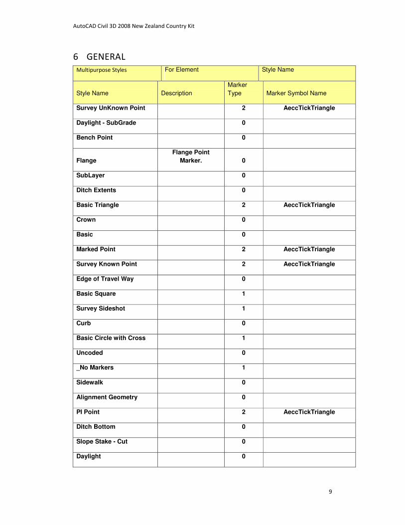
6 GENERAL
Multipurpose Styles For Element Style Name
Style Name Description
Marker
Type Marker Symbol Name
Survey UnKnown Point 2 AeccTickTriangle
Daylight - SubGrade 0
Bench Point 0
Flange
Flange Point
Marker. 0
SubLayer 0
Ditch Extents 0
Basic Triangle 2 AeccTickTriangle
Crown 0
Basic 0
Marked Point 2 AeccTickTriangle
Survey Known Point 2 AeccTickTriangle
Edge of Travel Way 0
Basic Square 1
Survey Sideshot 1
Curb 0
Basic Circle with Cross 1
Uncoded 0
_No Markers 1
Sidewalk 0
Alignment Geometry 0
PI Point 2 AeccTickTriangle
Ditch Bottom 0
Slope Stake - Cut 0
Daylight 0
AutoCAD Civil 3D 2008 New Zealand Country Kit
10
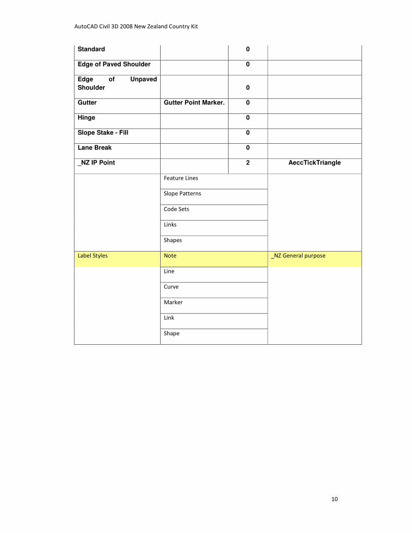
Standard 0
Edge of Paved Shoulder 0
Edge of Unpaved
Shoulder 0
Gutter Gutter Point Marker. 0
Hinge 0
Slope Stake - Fill 0
Lane Break 0
_NZ IP Point 2 AeccTickTriangle
Feature Lines
Slope Patterns
Code Sets
Links
Shapes
Label Styles Note _NZ General purpose
Line
Curve
Marker
Link
Shape

AutoCAD Civil 3D 2008 New Zealand Country Kit
11
7 POINTS
Point Styles Name Description
Style Name Description
Marker Symbol
Name
Marker
Size
2D Marker
Layer
2D Label
Layer
PTRE-3D Tree 6 1250 0 0
Utility Pole
Style for
utility pole. Utility Pole 0.0025
V-NODE-
POLE
V-NODE-
POLE
ICB AI_VASIS 0.0025 0 0
SV ws_stopv 0.0025 0 0
PTEM te_mh 0.0025 0 0
PP EL_POLE 0.0025 0 0
Basic 0.00254 V-NODE
V-NODE-
TEXT
WM ws_meter 0.0025 0 0
Horizontal Curve Point
Style for
horizontal
curve point. Station Mark 0.0025
V-CTRL-
HCPT
V-CTRL-
HCPT
Guy Pole
Style for
guy pole. Guy Pole 0.0025
V-NODE-
POLE
V-NODE-
POLE
PSIL PSIL 0.0025 0 0
Water Shutoff
Style for
water
shutoff. Water Shutoff 0.0025
V-NODE-
WATR
V-NODE-
WATR
PUNB PUNB 0.0025 0 0
PUNP PUNP 0.0025 0 0
SIGN tr_sign 0.0025 0 0
STAR PICKET su_bm 0.0025 0 0
Bound
Style for
bound. bound 0.0025
V-NODE-
BNDY
V-NODE-
BNDY
STA STA 0.0025
V-CTRL-
HCPT
V-CTRL-
HCPT
PPT Transformer PWML 0.0025 0 0
Sanitary Sewer Manhole Style for
sanitary
Sewer
Manhole 0.0025
V-NODE-
SSWR
V-NODE-
SSWR

AutoCAD Civil 3D 2008 New Zealand Country Kit
12
sewer
manhole.
COCO Tree 6 0.0025 0 0
Catch Basin
Style for
catch basin. Catch Basin 0.0025
V-NODE-
STRM
V-NODE-
STRM
Sign (single pole)
Style for
single pole
sign.
Single Pole
Sign 0.0025
V-NODE-
SIGN
V-NODE-
SIGN
Iron Pin
Style for
iron pin. Iron Pin 0.0025
V-NODE-
BNDY
V-NODE-
BNDY
TPIT te_pit 0.0025 0 0
Storm Sewer Manhole
Style for
storm sewer
manhole. Drainage MH 0.0025
V-NODE-
STRM
V-NODE-
STRM
TR Tree 10 0 0
Benchmark
Style for
benchmark. Benchmark 0.0025
V-CTRL-
BMRK
V-CTRL-
BMRK
STATION su_stn 0.0025 0 0
BOLLARD MS_BOLRD 0.0025 0 0
Gas Valve
Style for
gas valve. Gas Valve 0.0025
V-NODE-
NGAS
V-NODE-
NGAS
Vertical Curve Point
Style for
vertical
curve point. Station Mark 0.0025
V-CTRL-
VCPT
V-CTRL-
VCPT
Level Dot 0.0005 0 0
Hydrant (existing)
Style for
existing fire
hydrant Existing Hyd 0.0025
V-NODE-
WATR
V-NODE-
WATR
DRG - Drain Grate DR_GRATE 0.0025 0 0
BIN MH750 0.0025 0 0
Copy of New Point Style
Style for
tree Tree 6 20
V-NODE-
TREE
V-NODE-
TREE
Shrub - 5ft
Style for
shrub - 5'. Shrub 2 5
V-NODE-
TREE
V-NODE-
TREE
ELP el_lghtp 0.0025 0 0
PELB-Elec Pit PELB 0.0025 0 0

AutoCAD Civil 3D 2008 New Zealand Country Kit
13
Hydrant (proposed)
Style for
proposed
fire hydrant. Proposed Hyd 0.0025
V-NODE-
WATR
V-NODE-
WATR
Drill Hole
Style for
drill hole. Drill Hole 0.0025
V-NODE-
BNDY
V-NODE-
BNDY
Standard 0.001 0 0
Well
Style for fire
hydrant
well. Well 0.0025
V-NODE-
WATR
V-NODE-
WATR
PPL
El Pole
Point el_lghtp 0.0025 0 0
Water Valve
Style for
water valve. Water Valve 0.0025
V-NODE-
WATR
V-NODE-
WATR
PAYBOX ST_MS 0.0025 0 0
FH WS_FH 0.0025 0 0
SMH SW_MH 0.0025 0 0
SWMH SEW-MH 0.0025 0 0
PSLP el_lghtp 0.0025 0 0
Test Pit
Style for
test pit. Test Pit 0.0025
V-NODE-
WATR
V-NODE-
WATR
PSM su_psm 0.0025 0 0
Point Table Styles _NZ Point Coordinates
Style Style Name Description
Point Label
Styles _NZ No Labels
Point Label
Styles _NZ Code only
Point Label
Styles Land Desktop Point Style
Point Style with the same appearance Land
Desktop displayed Points
Point Label
Styles _NZ Level and Code
Point Label
Styles _NZ Raw Code only

AutoCAD Civil 3D 2008 New Zealand Country Kit
14
Point Label
Styles _NZ Pt Number only
Point Label
Styles _NZ CivCad
Point Label
Styles _NZ Level and Raw Code
Point Label
Styles _NZ Levels only
Point Label
Styles Standard Standard Style
Point Label
Styles _NZ PT Number Level Code
Point Label
Styles
_NZ PT Number Level Code
(Raw)
Description key Sets _NZ Numeric
_NZ Alpha

AutoCAD Civil 3D 2008 New Zealand Country Kit
15
8 SURFACES
Surface Style Name Description
_NZ 2D Borders Shows surface border as a 2D
_NZ Aspect Map
TIN triangles shaded based on
the triangle aspect - North
Azimuth orientation of the slope
_NZ Contours - Background 1m
_NZ Contours - Design - 0.1m
_NZ Contours - Design - 1m
_NZ Contours - NS - 0.2m
_NZ Contours - NS - 0.5m
_NZ Contours - NS - 1m
_NZ Contours - NS - 2m
_NZ Contours - NS - 5m
_NZ Contours & Triangles - 0.2m
_NZ Levels Shading
3D faces of the surface model,
colour coded based on level
range
_NZ No Display
_NZ Slope Arrows & Triangles
_NZ Slope Arrows & Watersheds
_NZ Slopes
_NZ Triangles - Design
_NZ Triangles - NS
_NZ Triangles & Points
Direction Table Style _NZ aspect
Slope Table Style _NZ Cut and Fill Depths
_NZ Levels
Slope Arrow Table Style _NZ Slope Arrows
Contour Table Style _NZ Contours

AutoCAD Civil 3D 2008 New Zealand Country Kit
16
WaterShed Table Style _NZ Watersheds
Watershed Label Style _NZ Watershed details Watershed areas based on
surface TIN.
Spot Elevation Label Style _NZ Spot Levels Surface spot level Label Style
_NZ Spot Levels - Angled Surface spot level Label Style
Slope Label Style _NZ Grade Label Grade label showing percent
character
_NZ Slope Label Showing rise : run as 1:2
Contour Label Style _NZ Dsgn Major Design Surface Major Contour
Label Style
_NZ Dsgn Minor Design Surface Minor Contour
Label Style
_NZ NS Minor Natural Surface Minor Contour
Label Style
_NZ User Contour
_NZ NS Major Natural Surface Major Contour
Label Style

AutoCAD Civil 3D 2008 New Zealand Country Kit
17
9 PARCEL
Parcel Styles Style Name Description
POS Public Open Space
ROAD RES Road Reserve lot
L New Zealand Lot
Parcel Segment Table
Styles _NZ Lot lines
Bearing and Length or Chord
Bearing and Radius
Parcel Area Table Styles _NZ Lot Areas Lot # and Size
Parcel Line Table Styles _NZ Bearings and Lengths
Parcel Curve Table Syles _NZ Arcs R & A & C & Ch details
Curve Segment Label
Styles _NZ Span Arc 10sec 10mm
_NZ Span Arc 1min 10mm
_NZ Arc 10sec 100mm
_NZ Span Arc 20sec 10mm
_NZ Arc 10sec 1m
_NZ Arc 20sec 10mm
_NZ Arc 1min 10mm
_NZ Span Arc 10sec 1m
_NZ Span Arc 5sec 10mm
_NZ Span Arc 10sec 100mm
_NZ Arc 5sec 10mm
_NZ Arc 10sec 10mm
Parcel Area Styles _NZ Site Block of Land - Overall
_NZ No L 999
_NZ No & Area
L 999
500m2
Parcel Line Label Styles
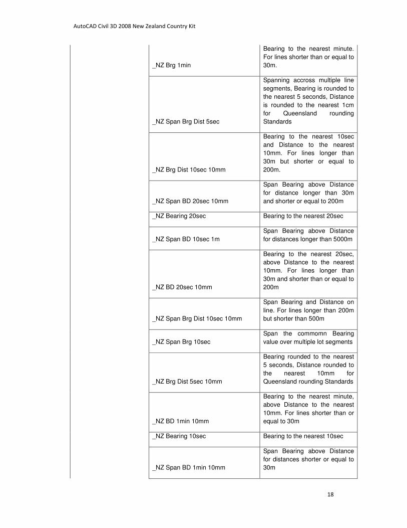
_NZ Brg Dist 1min 10mm
Bearing to the nearest minute
and Distance to the nearest
10mm. For lines shorter than or
equal to 30m.
AutoCAD Civil 3D 2008 New Zealand Country Kit
18
_NZ Brg 1min
Bearing to the nearest minute.
For lines shorter than or equal to
30m.
_NZ Span Brg Dist 5sec
Spanning accross multiple line
segments, Bearing is rounded to
the nearest 5 seconds, Distance
is rounded to the nearest 1cm
for Queensland rounding
Standards
_NZ Brg Dist 10sec 10mm
Bearing to the nearest 10sec
and Distance to the nearest
10mm. For lines longer than
30m but shorter or equal to
200m.
_NZ Span BD 20sec 10mm
Span Bearing above Distance
for distance longer than 30m
and shorter or equal to 200m
_NZ Bearing 20sec Bearing to the nearest 20sec
_NZ Span BD 10sec 1m
Span Bearing above Distance
for distances longer than 5000m
_NZ BD 20sec 10mm
Bearing to the nearest 20sec,
above Distance to the nearest
10mm. For lines longer than
30m and shorter than or equal to
200m
_NZ Span Brg Dist 10sec 10mm
Span Bearing and Distance on
line. For lines longer than 200m
but shorter than 500m
_NZ Span Brg 10sec
Span the commomn Bearing
value over multiple lot segments
_NZ Brg Dist 5sec 10mm
Bearing rounded to the nearest
5 seconds, Distance rounded to
the nearest 10mm for
Queensland rounding Standards
_NZ BD 1min 10mm
Bearing to the nearest minute,
above Distance to the nearest
10mm. For lines shorter than or
equal to 30m
_NZ Bearing 10sec Bearing to the nearest 10sec
_NZ Span BD 1min 10mm
Span Bearing above Distance
for distances shorter or equal to
30m

AutoCAD Civil 3D 2008 New Zealand Country Kit
19
_NZ Span Distance Special Integer
Rounded to the nearest whole
meter to support writing off
trailing zeroes with "m" suffix to
delineate 6 from 9, 18 from 81,
89 from 68 etc.
_NZ Span Distance 10mm
Distance rounded to the nearest
1cm spanning accross multiple
lots
_NZ Span Brg Dist 1min 10mm
Span Bearing and Distance on
line. For lines shorther than 30m
_NZ Span Brg 1min
Span the commomn Bearing
value over multiple lot segments
_NZ Span Distance 100mm
Distance rounded to the nearest
100mm spanning accross
multiple lots
_NZ Span Brg Dist 10sec 100mm
Span Bearing and Distance on
line. For lines longer than 500m
but shorter than 5000m
_NZ Span BD 10sec 10mm
Span Bearing above Distance
for distance longer than 200m
but shorter than or equal to
500m
_NZ BD 10sec 10mm
Bearing to the nearest 10sec,
above Distance to the nearest
10mm for lines longer than
200m but shorter or equal to
500m
_NZ Distance Special Integer
Rounded to the nearest whole
meter to support writing off
trailing zeroes with "m" suffix to
delineate 6 from 9, 18 from 81,
89 from 68 etc.
_NZ Span Brg Dist 10sec 1m
Span Bearing and Distance on
line. For lines longer than
5000m
_NZ Bearing 1minute Bearing to the nearest 1minute
_NZ Span BD 10sec 100mm
Span Bearing above Distance
for distance longer than 500m
but shorter than or equal to
5000m
_NZ Span Distance 1m Distance rounded to the nearest
1m spanning accross multiple

AutoCAD Civil 3D 2008 New Zealand Country Kit
20
lots
_NZ Bearing 5sec Bearing to the nearest 5sec
_NZ Span Distance Integer
Rounded to the nearest whole
meter to support writing off
trailing zeroes for round
distances *.00
_NZ Distance 10mm
Distance rounded to the nearest
1cm spanning accross multiple
lots
_NZ Brg Dist 10sec 1m
Bearing to the nearest 10sec
and Distance to the nearest 1m.
For lines longer than 5000m.
_NZ Brg 10sec
Bearing to the nearest 10sec.
For lines longer than 5000m.
_NZ Dist 1m
Distance to the nearest 1m. For
lines longer than 5000m.
_NZ Distance 1m
Distance rounded to the nearest
1m
_NZ Distance 100mm
Distance rounded to the nearest
100mm spanning accross
multiple lots
_NZ Brg Dist 20sec 10mm
Bearing to the nearest 20sec
and Distance to the nearest
10mm. For lines longer than
30m but shorter or equal to
200m.
_NZ Brg 20sec
Bearing to the nearest 20sec.
For lines longer than 30m but
shorter or equal to 200m.
_NZ BD 10sec 100mm
Bearing to the nearest 10sec,
above Distance to the nearest
100mm. For lines longer than
500m but shorter or equal to
5000m
_NZ Distance Integer
Rounded to the nearest whole
meter to support writing off
trailing zeroes for round
distances *.00
_NZ Span Brg Dist 20sec 10mm
Span Bearing and Distance on
line. For lines longer than 30m
but shorter than 200m

AutoCAD Civil 3D 2008 New Zealand Country Kit
21
_NZ Span Brg 20sec
Span the commomn Bearing
value over multiple lot segments
_NZ BD 5sec 10mm
Bearing rounded to the nearest
5 seconds above Distance
rounded to the nearest 10mm
for Queensland rounding
Standards
_NZ Span BD 5sec 10mm
Bearing rounded to the nearest
5 seconds above Distance
rounded to the nearest 1cm for
Queensland rounding Standards
- spanning accross multiple lots
_NZ Span B 5sec
Bearing rounded to the nearest
5 seconds for Queensland
rounding Standards - spanning
accross multiple lots
_NZ Span D 10mm
_NZ Brg Dist 10sec 100mm
Bearing to the nearest 10sec
and distance to the nearest
100mm. For lines longer than
500m but shorter or equal to
5000m).
_NZ BD 10sec 1m
Bearing to the nearest 10sec,
above Distance to the nearest
metre. For lines longer than
5000m

AutoCAD Civil 3D 2008 New Zealand Country Kit
22
10 GRADING
Grading Criteria
Sets Name Description
_NZ General purpose
Grading Styles _NZ Cut Slope Tadpoles
_NZ Generic Generic purpose Grading style
_NZ Cut Slope Lines
_NZ Fill Slope Tadpoles

AutoCAD Civil 3D 2008 New Zealand Country Kit
23
11 ALIGNMENT
Alignment
Styles
Name Description
_NZ Centreline General centreline design style
_NZ Strings General strings design style
_NZ Design General centreline design style
Label Sets Name Label Styles Name
_NZ All Labels Major Station _NZ Perpendicular Tick
Minor Station _NZ Tick Only
Geometry Point _NZ GP Data
Design Speed _NZ Speed Chainage
_NZ No Labels
_NZ Geometry Tick Geometry Point _NZ Tick Only
_NZ Major Minor and
Geometry
Major Station _NZ Perpendicular Tick
Minor Station _NZ Tick Only
Geometry Point _NZ GP Data
_NZ Major Parallel
and Geometry Tick
Major Station _NZ Parallel Tick
Geometry Point _NZ Tick Only
_NZ Major and
Geometry
Major Station _NZ Perpendicular Tick
Geometry Point _NZ GP Data
_NZ Major and Minor Major Station _NZ Perpendicular Tick
Minor Station _NZ Tick Only
_NZ Highway Labels Major Station _NZ Perpendicular Tick
Minor Station _NZ Tick Only
Geometry Point _NZ GP Data
Design Speed _NZ Speed Chainage
Table Styles Name Description

AutoCAD Civil 3D 2008 New Zealand Country Kit
24
Segment Table
Styles
_NZ Line Arc Spiral Lengths
_NZ Chainage Easting Northing Radii Bearing IP
_NZ Ch East North Bear Rad Tang Ang Length
Spiral Table
Styles
_NZ Spirals
Line Table Styles
_NZ Lines
Curve Table
Styles
_NZ Arcs
Tangent
Intersection
Styles
Name Description
_NZ IP Details Detailed design layout and
setout data for the curve
arc segment displayed
above the tangent IP.
Design Speed
Styles
Name Description
_NZ Speed Chainage Design Speed above
Chainage
Station Equation
Styles
Name Description
_NZ Chainage Change To label a point on
alignment where chainage
values have to continue
from a different base. Eg.
chainage 1234.56 becomes
chainage 0.00 and all
chainages ahead continue
to grow from chainage
value 0.00
Station Offset Name Description
_NZ Right side Ch & Offset Line
_NZ Ch & Offset Table
_NZ Left side Ch & Offset Line
Spiral Styles Name Description
AutoCAD Civil 3D 2008 New Zealand Country Kit
25
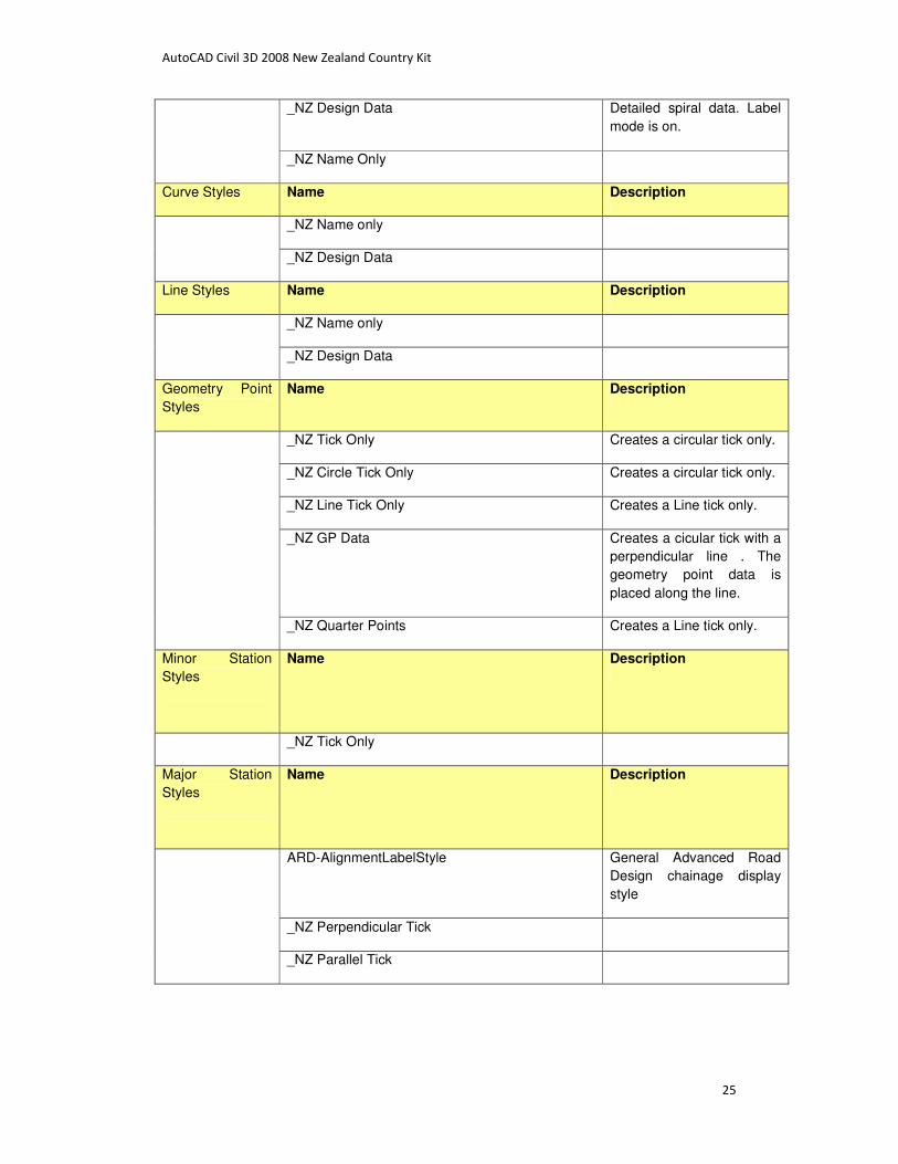
_NZ Design Data Detailed spiral data. Label
mode is on.
_NZ Name Only
Curve Styles Name Description
_NZ Name only
_NZ Design Data
Line Styles Name Description
_NZ Name only
_NZ Design Data
Geometry Point
Styles
Name Description
_NZ Tick Only Creates a circular tick only.
_NZ Circle Tick Only Creates a circular tick only.
_NZ Line Tick Only Creates a Line tick only.
_NZ GP Data Creates a cicular tick with a
perpendicular line . The
geometry point data is
placed along the line.
_NZ Quarter Points Creates a Line tick only.
Minor Station
Styles
Name Description
_NZ Tick Only
Major Station
Styles
Name Description
ARD-AlignmentLabelStyle General Advanced Road
Design chainage display
style
_NZ Perpendicular Tick
_NZ Parallel Tick

AutoCAD Civil 3D 2008 New Zealand Country Kit
26
12 PROFILE
Station Elevation
Label Styles
Style Name Description
_NZ VC Min
_NZ VC End
_NZ VC IP
_NZ VC Max
_NZ Crest Curve
_NZ VC
_NZ VC Start
_NZ Vertical Curve
_NZ Sag Curve
Tangent Label _NZ Design Tangent Slope
_NZ Design Tangent Grade
Grade Break Label _NZ Vertical with line
Major Station Label Perpendicular with Tick
Minor Station Label Perpendicular with Tick
Profile View _NZ Design Surface
_NZ Existing Surface Two
_NZ Existing Surface
Horizontal Geometry
Point Label
_NZ Horiz Align TP
Label Set Style Name Description Style Name
_NZ No Labels
_NZ Existing Surface Geometry Point _NZ Horiz Align TP
_NZ Design Basic Set Grade Break _NZ Vertical with line
Line _NZ Design Tangent Grade
Sag Curve _NZ Sag Curve
Crest Curve _NZ Crest Curve

AutoCAD Civil 3D 2008 New Zealand Country Kit
27
_NZ Design VC Vertical Curves label style
Label Styles Style Name
Line _NZ Design Tangent Grade
Sag Curve _NZ Vertical Curve
Crest Curve _NZ Vertical Curve
_NZ VC Details Line _NZ Design Tangent Grade
Sag Curve _NZ VC
Sag Curve _NZ VC End
Sag Curve _NZ VC IP
Sag Curve _NZ VC Max
Sag Curve _NZ VC Min
Sag Curve _NZ VC Start
Crest Curve _NZ VC
Crest Curve _NZ VC End
Crest Curve _NZ VC IP
Crest Curve _NZ VC Max
Crest Curve _NZ VC Min
Crest Curve _NZ VC Start

AutoCAD Civil 3D 2008 New Zealand Country Kit
28
13 PROFILE VIEW
Profile View
Styles
Name Description
_NZ Highway Design no Title
_NZ Road Presentation 5x 5 times vertically exaggerated
_NZ Pipes
_NZ Pipes no Title
_NZ Road Presentation 20x no Title 20 times vertically exaggerated
_NZ Road Design
_NZ Road Presentation 10x no Title 10 times vertically exaggerated
_NZ Road Presentation 10x 10 times vertically exaggerated
_NZ Road Presentation 5x no Title 5 times vertically exaggerated
_NZ Road Presentation 20x 20 times vertically exaggerated
_NZ Road Design no Title
_NZ Highway Design
Station Elevation
Label Styles
Name Description
_NZ Chainage & Level Label For Long section details
Depth Label
Styles
_NZ Slope Rise over Run
_NZ Depth Label
_NZ Grade percents
Band Sets Name Description Style Name
_NZ Pipes With Depths to
Invert no Title
_NZ Highway Design no
Title
Vert Geo _NZ Vertical Geometry no Title
Horz Geo _NZ Single Carriageway no Title
Profile Data _NZ Depths P2 - P1 no Title

AutoCAD Civil 3D 2008 New Zealand Country Kit
29
Profile Data _NZ Design Levels P2 no Title
Profile Data _NZ Existing Levels P1 no Title
Profile Data _NZ Chainage no Title
_NZ Surface Levels Only Profile Data _NZ Existing Levels P1
Profile Data _NZ Chainage
_NZ Pipes
_NZ Simple Design Profile Data _NZ Design Levels P2
Profile Data _NZ Existing Levels P1
Profile Data _NZ Chainage
_NZ Pipes no Title
_NZ Road Design Vert Geo _NZ Vertical Geometry
Horz Geo _NZ Single Carriageway
Profile Data _NZ Depths P2 - P1
Profile Data _NZ Design Levels P2
Profile Data _NZ Existing Levels P1
Profile Data _NZ Chainage
_NZ Road Design no Title Vert Geo _NZ Vertical Geometry no Title
Horz Geo _NZ Single Carriageway no Title
Profile Data _NZ Depths P2 - P1 no Title
Profile Data _NZ Design Levels P2 no Title
Profile Data _NZ Existing Levels P1 no Title
Profile Data _NZ Chainage no Title
_NZ Pipes With Depths to
Invert
_NZ Highway Design Vert Geo _NZ Vertical Geometry
Horz Geo _NZ Single Carriageway
Profile Data _NZ Depths P2 - P1
Profile Data _NZ Design Levels P2
Profile Data _NZ Existing Levels P1
AutoCAD Civil 3D 2008 New Zealand Country Kit
30
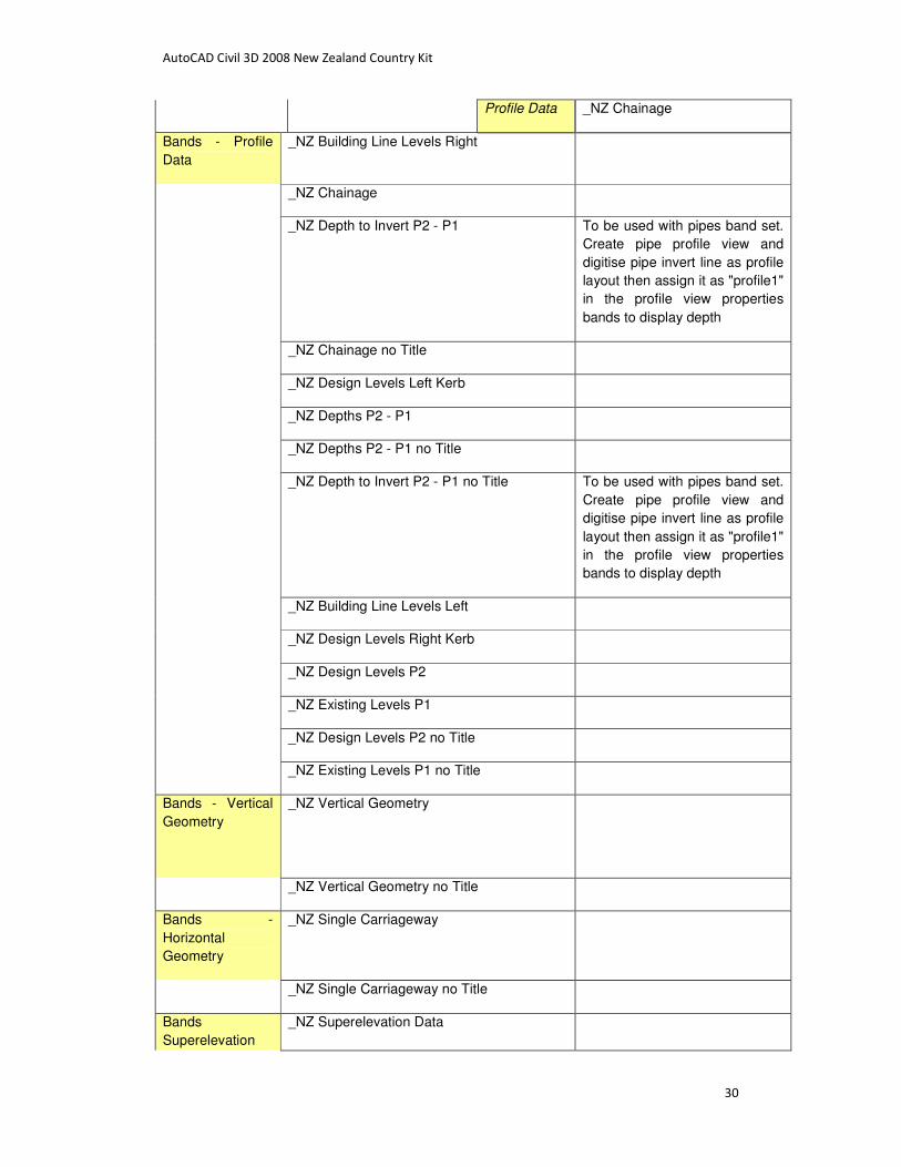
Profile Data _NZ Chainage
Bands - Profile
Data
_NZ Building Line Levels Right
_NZ Chainage
_NZ Depth to Invert P2 - P1 To be used with pipes band set.
Create pipe profile view and
digitise pipe invert line as profile
layout then assign it as "profile1"
in the profile view properties
bands to display depth
_NZ Chainage no Title
_NZ Design Levels Left Kerb
_NZ Depths P2 - P1
_NZ Depths P2 - P1 no Title
_NZ Depth to Invert P2 - P1 no Title To be used with pipes band set.
Create pipe profile view and
digitise pipe invert line as profile
layout then assign it as "profile1"
in the profile view properties
bands to display depth
_NZ Building Line Levels Left
_NZ Design Levels Right Kerb
_NZ Design Levels P2
_NZ Existing Levels P1
_NZ Design Levels P2 no Title
_NZ Existing Levels P1 no Title
Bands - Vertical
Geometry
_NZ Vertical Geometry
_NZ Vertical Geometry no Title
Bands -
Horizontal
Geometry
_NZ Single Carriageway
_NZ Single Carriageway no Title
Bands
Superelevation
_NZ Superelevation Data

AutoCAD Civil 3D 2008 New Zealand Country Kit
31
Data
_NZ Superelevation Data no Title
Bands Sectional
Dat
_NZ Section Line Data
_NZ Section Line Data no Title
Bands Pipe
Network
_NZ Ground Levels
_NZ Ground Levels no Title
_NZ Invert Levels
_NZ Invert Levels no Title
_NZ Pipe Data
_NZ Pipe Data no Title
_NZ Pit Chainage
_NZ Pit Chainage no Title
_NZ Rim Levels
_NZ Rim Levels no Title
_NZ Sump Depth
_NZ Sump Depth no Title
_NZ Trench Type
_NZ Trench Type no Title

AutoCAD Civil 3D 2008 New Zealand Country Kit
32
14 SAMPLE LINES
Sample Line Styles Name Description
_NZ Road Sections Sample Lines Metric, for use with roads.
Sample Line Label Styles _NZ Chainage only

AutoCAD Civil 3D 2008 New Zealand Country Kit
33
15 SECTIONS
Section Styles Name Description
_NZ Existing Ground
_NZ Design Datum
_NZ Design Ground
Label Sets _NZ No Labels Used for Corridor Design
Surface Sections in Section
Views. No labeling of section
segments in section view is
implemented with this set of
styles. The selected points
offset/level and segment grade
labels are defined by the
subassembly code set's label
styles
_NZ Grade Break Points
_NZ Existing Section Data Add labels to this Style to suit
the Natural Surface section
labeling
_NZ Crossgrades
Major Offset Label Styles _NZ Level
Minor Offset Label Styles _NZ Offset Offset
Grade Break Label Styles _NZ Section Points Design data
Segment Label Styles _NZ Section Grades

AutoCAD Civil 3D 2008 New Zealand Country Kit
34
16 SECTION VIEWS
Section View Styles Name Description
_NZ QLD Rural Roads Where the DATUM, Parent
Alignment and Chainage are
shown similar to the Profile View
Style. This is a recommended
style for better stacking of
section views on the page.
_NZ Road Section
_NZ Full Section
Group Plot Styles _NZ Plot by Page 500
Basic
_NZ Plot All Sections Plot All Sections for the sample
line group
_NZ Plot by Page
_NZ Plot by Page 100
_NZ Plot by Page 200
Sheet Styles _NZ A1 500
Basic1
_NZ A1 (Landscape) A1 Sheet layout in Landscape
_NZ A1 200 Compact
_NZ A1
_NZ A1 100
_NZ A1 200
_NZ Compact Section Where the DATUM, Parent
Alignment and Chainage are
shown similar to the Profile View
Style. This is a recommended
style for better stacking of
section views on the page.
Offset Elevation Label
Styles
_NZ Offset and Level
Grade Label Styles _NZ Section View Depth Grade

AutoCAD Civil 3D 2008 New Zealand Country Kit
35
Band Sets _NZ Section QLD Rural Section only without Band Data.
To be used with Corridor Point
Code Labels only.Use with the
Compact Section View Style.
Alignment Name, Chainage and
Datum included
_NZ Segment Widths and Grades Cross section segments labelled
with widths and grades in two
bands.
_NZ Section Standard Design Levels, Existing Levels
and Offsets
_NZ Section Full Set
_NZ Sections Segment Data Cross section segments labelled
with widths and grades in two
bands.
Band - Section Data _NZ QLD Rural Roads Levels
_NZ Offsets Standard cross sections offsets
_NZ Design Levels Corridor Top Surface Levels
_NZ Existing Levels Existing Surface
_NZ Datum Levels Corridor Datum surface levels
Band - Section Segment _NZ Segment Grades
_NZ Segment Offsets Standard cross sections offsets
_NZ Segment Widths Corridor Top Surface Levels
Table Styles Total
Volume
_NZ Segment Grades
_NZ Segment Offsets Standard cross sections offsets
_NZ Segment Widths Corridor Top Surface Levels
Table Styles Material _NZ Segment Grades
_NZ Segment Offsets Standard cross sections offsets
_NZ Segment Widths Corridor Top Surface Levels

AutoCAD Civil 3D 2008 New Zealand Country Kit
36
17 PIPE RULES
Pipe Rules Name Description
_NZ General purpose Localized C3DNetworkRules.dvb
AutoCAD Civil 3D 2008 New Zealand Country Kit
37
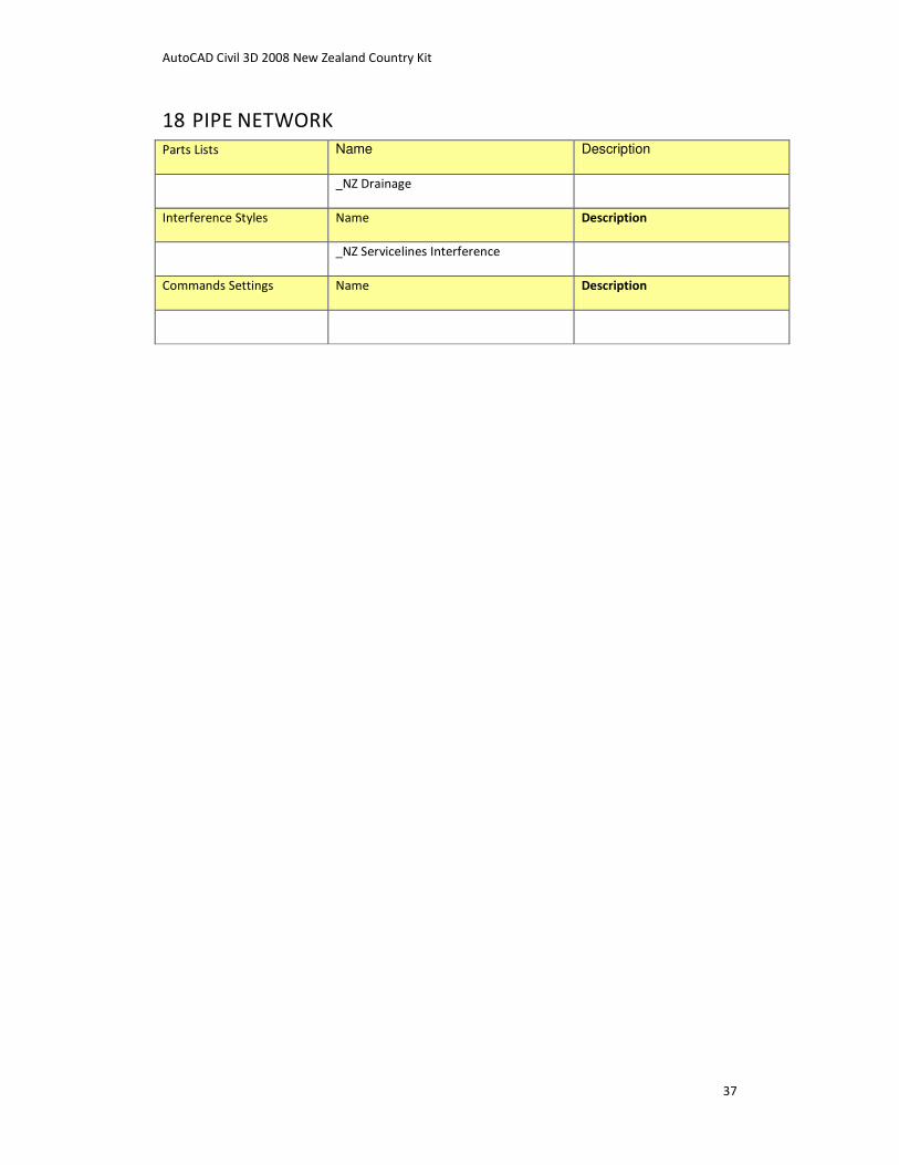
18 PIPE NETWORK
Parts Lists Name Description
_NZ Drainage
Interference Styles Name Description
_NZ Servicelines Interference
Commands Settings Name Description

AutoCAD Civil 3D 2008 New Zealand Country Kit
38
19 PIPE
Pipe Styles Name Description
_NZ Crossing Drainage Pipe
_NZ Drainage Pipe
_NZ Single Line Drainage Pipe
Pipe Rule Set _NZ Drainage Pits
_NZ Sewer Pits
Label Styles Plan Profile _NZ Drainage Pipe Data
_NZ Drainage Pipe Name
Label Styles Crossing
Section
_NZ Drainage Pipe
_No Labels
Table Styles _NZ Pipe Schedule

AutoCAD Civil 3D 2008 New Zealand Country Kit
39
20 STRUCTURE
Structure Styles Name Description
_NZ Drainage Pit
_NZ Sewer
_NZ SEP
Structure Rule Set _NZ Drainage Pits
_NZ Sewer Pits
Label Styles _NZ Drainage Pit Data
_NZ Drainage Pit Name
Table Styles _NZ Pit Schedule

AutoCAD Civil 3D 2008 New Zealand Country Kit
40
21 CORRIDOR DESIGN STANDARDS
Name Description
New Zealand _NZ Road Design Guidelines.xml

AutoCAD Civil 3D 2008 New Zealand Country Kit
41
22 CORRIDOR
Corridor Styles Name Description
_NZ Design
Commands

AutoCAD Civil 3D 2008 New Zealand Country Kit
42
23 ASSEMBLY
Assembly Styles Name Description
_NZ Assembly Style
Commands

AutoCAD Civil 3D 2008 New Zealand Country Kit
43
24 SUBASSEMBLY
Subassembly Styles Name Description
Commands

AutoCAD Civil 3D 2008 New Zealand Country Kit
44
25 QUANTITY TAKEOFF
Quantity Takeoff Criteria Name Description
_NZ General purpose
Table Styles Total Volume _NZ Cumulative Earthworks Table
Table Styles Material
Volume
_NZ Material Table

AutoCAD Civil 3D 2008 New Zealand Country Kit
45
26 QUANTITIES REPORT STYLE SHEETS
Name Description
Scripts StationFormatting.xsl
NumberFormatting.xsl
Stylesheets Select Material.xsl
Mass Haul - Multiple Materials.xsl
earthwork.xsl

AutoCAD Civil 3D 2008 New Zealand Country Kit
46
27 SURVEY
Name Description
Survey Database Settings _NZ SurveyDb Settings.sdb_set
Survey Equipment Database _NZ Common Survey Equipment.edb
Extended Properties Definition _NZ Prototype LandXML.sdx-def The e-plan specification is still
under development.
Figure Prefix Database _NZ Figure Prefix Database.fdb
Network Styles _NZ Networks
Figure Styles _NZ Figures

AutoCAD Civil 3D 2008 New Zealand Country Kit
47
28 VIEW FRAME GROUP
Commands Name Description

AutoCAD Civil 3D 2008 New Zealand Country Kit
48
29 VIEW FRAME
View Frame Styles Name Description
_NZ View Frame
Label Styles View Frame _NZ View Frame General purpose

AutoCAD Civil 3D 2008 New Zealand Country Kit
49
30 MATCH LINE
Name Description
Match line Styles _NZ Matchline Plan
_NZ Matchline Profile
Label Styles Match Line
Left
_NZ Matchline Left
Label Styles Match Line
Right
_NZ Matchline Right