Embed Size (px)
Citation preview
NEW YORK CITY TRANSIT
New Train Procurement for NYCT Division A (R142)
R142-R142A Compatibility
Propulsion Network
Compatibility
CDRL : N/A
Prepared : Matthieu Vanasse
Project Engineer, System Engineering
Verified : Michel Juteau
Manager, System Engineering
Approved : Richard Leclerc
Manager, System Engineering Name / Title, Group Signature Date
Document No. 043-BRA-0077 Rev. 4
The information, technical data and the designs disclosed herein are the exclusive property of Bombardier Inc. or contain proprietary rights of others and are not to be used or disclosed without the written consent of Bombardier Inc. The recipient of this document, by its retention and use agrees to hold in confidence the technical data and designs contained herein. The foregoing shall not apply to persons having proprietary rights to such information, technical data or such designs to the extent that such rights exist.
Date 1999.08.30(yyyy.mm.dd)
© 2002 Bombardier Inc.
R142-R142A Compatibility 043-BRA-0077 Propulsion Network Revision 4
Page 2 of 23
Document Revisions
Revision Date (yyyy.mm.dd) Description of changes
R142-R142A Compatibility 043-BRA-0077 Propulsion Network Revision 4
Page 3 of 23
Table of content 1. Scope ...................................................................................................................................... 5 2. References .............................................................................................................................. 5 3. Definitions and abbreviations ................................................................................................. 6 4. General Description ................................................................................................................ 7
4.1 Redundant LonWorks FTT-10A Propulsion Network ......................................................7 4.2 Master Controller .................................................................................................................7 4.3 Cab Interface Unit................................................................................................................7 4.4 Propulsion/Brake Control ....................................................................................................7 4.5 TMS system .........................................................................................................................8
5. LON interface hardware requirements.................................................................................... 8 5.1 Network configuration.........................................................................................................8 5.2 Propulsion Network restricted use.......................................................................................8 5.3 Systems Requirements in Low Voltage Condition..............................................................8
6. Master Controller.................................................................................................................... 9 6.1 General description ..............................................................................................................9 6.2 Transmitted information ......................................................................................................9 6.3 Special functions................................................................................................................10 6.4 Transmission mode ............................................................................................................10 6.5 Message format..................................................................................................................11
7. Cab Interface Unit................................................................................................................. 12 7.1 General description ............................................................................................................12 7.2 Transmitted information ....................................................................................................13 7.3 Special functions................................................................................................................14 7.4 Transmission mode ............................................................................................................14 7.5 Message format..................................................................................................................15
8. Propulsion/Brake Control ..................................................................................................... 17 8.1 General Description ...........................................................................................................17 8.2 Special functions................................................................................................................17
9. TMS interface ...................................................................................................................... 18 9.1 General description ............................................................................................................18
10. Propulsion Network configuration.................................................................................. 19 10.1 Timing requirements.........................................................................................................19
11. Propulsion Network vs. Train operation ......................................................................... 20 11.1 General .............................................................................................................................20 11.2 Command updates ............................................................................................................20 11.3 Detection of multiple active Master Controller and Cab Interface Unit ..........................20 11.4 Train power-up .................................................................................................................21 11.5 PBC reaction to static circular counter values..................................................................21 11.6 PBC reaction to invalid Master Controller information ...................................................21 11.7 PBC reaction to invalid Cab Interface Unit information..................................................22 11.8 Propulsion response time..................................................................................................22 11.9 Faulty Networks ...............................................................................................................23
R142-R142A Compatibility 043-BRA-0077 Propulsion Network Revision 4
Page 4 of 23
List of Figures Figure 1 - Master Controller message format ................................................................................11 Figure 2 - Cab Interface Unit message format...............................................................................15 List of Tables Table 1 - Master Controller handle position encoding ..................................................................12 Table 2 - Normal operation traffic evaluation ...............................................................................19 Table 3 - All Master Controller keyed on traffic evaluation .........................................................20 Table 4 - Worst case Master Controller message transmission times ...........................................22
R142-R142A Compatibility 043-BRA-0077 Propulsion Network Revision 4
Page 5 of 23
1. Scope
The scope of the present document is to define the information transmitted on the propulsion network that is required for compatibility between the R142 and R142A cars.
The information contained in this document is considered sufficient to allow duplication of the propulsion Network functionality on the R142A and is not intended to allow duplication of the hardware configuration of the Propulsion Network.
The information contained herein reflect the status of the design at the moment the document was issued and is subject to change as the design of the various interfaces evolve.
2. References
NYCT- Subway car procurement for the A Division - Section V - Technical Specification - New Car Procurement Contract R34142 (R142).
Echelon Corporation - LonWorks FTT-10A Transceiver User’s Guide - Document No. 078-0156-01A.
R142-R142A Compatibility 043-BRA-0077 Propulsion Network Revision 4
Page 6 of 23
3. Definitions and abbreviations
ADCL All Door Closed and Locked
CIU Cab Interface Unit
Forward motion Forward motion is defined at car level with respect to its end #1; any car within a Unit is defined to move forward when its end # 1 is leading. Forward motion is commanded if a request to move forward is received on the Right Side Propulsion Network or if a request to move reverse is received on the Left Side Propulsion Network.
LS Left Side. The left side is defined at car level with respect to a passenger looking at the end #1 from inside the car.
LSB Least Significant Bit.
LVDN Low Voltage Distribution Network.
MC Master Controller.
MDS Monitoring and Diagnostic System.
MSB Most Significant Bit.
PBC Propulsion Brake Control.
Reverse motion Reverse motion is defined at car level with respect to its end #1; any car within a Unit is defined to move reverse when its end # 1 is trailing. Reverse motion is commanded if a request to move reverse is received on the Right Side Propulsion Network or if a request to move forward is received on the Left Side Propulsion Network.
RS Right Side. The right side is defined at car level with respect to a passenger looking at the end #1 from inside the car.
TCU Truck Control Unit.
T/O Train Operator status
TMS Train Multiplexer System
R142-R142A Compatibility 043-BRA-0077 Propulsion Network Revision 4
Page 7 of 23
4. General Description
4.1 Redundant LonWorks FTT-10A Propulsion Network
4.1.1 The Propulsion Network is a redundant network where two completely independent network transmitting the same information are used to achieve the highest probability of mission completion for the train.
4.1.2 Each Propulsion Network is logically named according to a functional representation of its location within a car; that is the Right Side (RS) Propulsion Network and the Left Side (LS) Propulsion Network.
4.2 Master Controller
4.2.1 The Master Controller supplied by Wabco is located in the Cab cars of a Unit and is used to convert the operator actions into Propulsion Network commands.
4.2.2 The Master Controller broadcast its messages (in opposition to addressing a single node) on the network. All nodes connected to the Propulsion Network shall then receive the same messages at the same time and react accordingly.
4.3 Cab Interface Unit
4.3.1 For the purpose of this document, the Cab Interface Unit is defined as the system or component(s) that is used to convert the discrete trainline status and some console control signal into Propulsion Network commands.
4.3.2 The Cab Interface Unit broadcasts its messages on the network. All nodes connected to the Propulsion Network shall then receive the same messages at the same time and react accordingly.
4.3.3 Although the R142 and R142A equipment implementing the actual function might be physically different, they shall accurately duplicate the Cab Interface Unit functionality described herein.
4.4 Propulsion/Brake Control
4.4.1 For the purpose of this document, the Propulsion/Brake Control (PBC) is defined as the system or component(s) in each car, that is receiving and reacting to the information from the Master Controller and from the Cab Interface Unit on the Propulsion Network.
4.4.2 Although the R142 and R142A equipment implementing the actual function might be physically different, they shall accurately duplicate the Propulsion/Brake control functionality described herein.
R142-R142A Compatibility 043-BRA-0077 Propulsion Network Revision 4
Page 8 of 23
4.5 TMS system
4.5.1 The Telephonics TMS system is transferring information between Unit that are coupled together. For the purpose of the Propulsion Network, the TMS interface is isolating the Propulsion Network from local communication messages of adjacent Units.
4.5.2 Messages broadcasted by the Master Controller and the Cab Interface Unit are transmitted to other Units through the TMS while any other messages that are local to an R142 or R142A Unit and used for purpose other than that described herein are not.
5. LON interface hardware requirements
5.1 Network configuration
5.1.1 The R142 Propulsion Network configuration is static; no node number reassignment is required for any of the considered Unit and train configuration. Each Unit Propulsion Network is completely isolated from adjacent Units by the TMS system.
5.1.2 The R142 system’s node number are assigned at equipment assembly and configuration time in the factory.
5.1.3 All of the nodes connected to the Propulsion Network will share the same Domain and Subnet address on both the RS and LS Propulsion Network as follow: • Domain address length = 1 • Domain address = 1 • Subnet address = 1
5.2 Propulsion Network restricted use
5.2.1 Use of the Propulsion Network for interfacing purpose between Units other than those described in this document shall be submitted to Bombardier; the technical proposal shall clearly define the interfacing and network resources requirement (purposes, estimated bandwidth, expected priority, etc.).
5.3 Systems Requirements in Low Voltage Condition
5.3.1 The Master Controller and the Cab Interface Unit on both the R142 and the R142A Units shall operate normally over a voltage range of 20 to 44 VDC. The Master Controller and the Cab Interface Unit shall monitor their Low Voltage Power Input and transmit its condition on the Network.
R142-R142A Compatibility 043-BRA-0077 Propulsion Network Revision 4
Page 9 of 23
6. Master Controller
6.1 General description
6.1.1 The Master Controller is built from two electrically independent units that each send information on its respective Propulsion Network. The Master Controller electronic section is powered only when the Master Controller is keyed-in, thus preventing the issuance of any message when it is inactive.
6.1.2 The Master Controller electronic essentially converts the electrical signal received from its various devices into LON network compatible signals. Each half of the Master Controller shall transmit the status of its various devices on the network without any interpretation or processing of the signals except as otherwise defined in section 6.3.
6.1.3 The Master Controller is configured to receive messages from the Cab Interface Unit (message code 01h). The received Cab Interface Unit message is used to perform the door interlocking functionality described in section 6.3.1.
6.2 Transmitted information
6.2.1 The following information shall be transmitted by the Master Controller: Forward/Reverse: Mutually exclusive status of the direction selected on the
reverser switch by the operator. Information sent on the RS Propulsion Network is the complement of that sent on the LS Propulsion Network. The "complementary" function shall be performed at the reverser switch electrical contact wiring level.
Power/Brake: Mutually exclusive status of the Master Controller handle position indicating whether it is in the brake or in the power range. Used to assess the encoder value.
Deadman: Status of the Master Controller handle Deadman state.
Encoder: The digital value of the Master Controller handle encoder position.
Full Service: Master Controller in Full Service brake position; used to control the brake pipe charging sequence.
Door Interlock restriction Status bit indicating the Master Controller logic itself may be creating an encoder vs. Power/Brake switch mismatch for door interlocking purpose.
LVPI Status bit indicating the Master Controller Low Voltage Power Input is within the valid range.
MCID The Neuron Chip identification
CC Circular Counter incremented at each transmission
R142-R142A Compatibility 043-BRA-0077 Propulsion Network Revision 4
Page 10 of 23
6.3 Special functions
6.3.1 Door interlock
6.3.1.1 In order to implement the functionality requested under section 11.10.2 of the NYCT Specification, the Master Controller shall transmit an encoder value corresponding to "Coast" when the Train Operator (T/O) status received from the Cab Interface Unit is not indicating an All Door Closed and Locked (ADCL) condition and the Master Controller handle is in a power position. Unless otherwise requested, the other functionalities of the Master Controller remain unaffected..
6.3.1.2 Paragraph deleted.
6.3.1.3 In addition, while the T/O status is not indicating an ADCL condition, mismatch between the Power/Brake status and Encoder value could occur and are acceptable. To eliminate possible false diagnostics, whenever the Master Controller is restricting its encoder value, it will set the Door Interlock Restriction status bit described in section 6.2.1
6.3.1.4 In cases where the Master Controller receives conflicting information (bit mismatch) regarding the T/O Status from the CIU, the Master Controller shall consider that the T/O is not in ADCL condition.
6.3.2 Circular counter
6.3.2.1 In order to ensure the same message is not continuously send by a defective Master Controller, a message counter incremented at each transmission is part of each messages send by the Master Controller.
6.3.2.2 The message counter is implemented as an 8 bit value that is unity incremented at each transmission.
6.4 Transmission mode
6.4.1 Each half of the Master Controller broadcast its complete status information within a unique message on its respective network connection each and every 49 ms.
6.4.2 The Master Controller Propulsion Network LON interfaces are each assigned a node and group number as follow: • LON interface on the RS Propulsion Network: Node = 1, Group = 1 • LON interface on the LS Propulsion Network: Node = 1, Group = 1
6.4.3 The Master Controller transmit its information using the Domain Broadcast addressing mode, thus ensuring that all nodes connected to the Propulsion Network will accept its messages. No acknowledgment, authentication or message repeating services shall be required from the network in order to minimize the number of information packet transiting on the Propulsion Network.
R142-R142A Compatibility 043-BRA-0077 Propulsion Network Revision 4
Page 11 of 23
6.4.4 In order to avoid possible repeated collision with other messages from other systems and to benefit from the p-persistent CSMA algorithm of the LonTalk® protocol, no priority assignment are made to the Master Controller messages.
6.4.5 The Master Controller message is assigned the message number 00h (message table information).
6.5 Message format
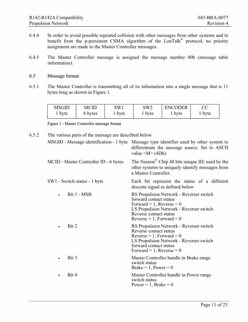
6.5.1 The Master Controller is transmitting all of its information into a single message that is 11 bytes long as shown in Figure 1.
MSGID 1 byte
MCID 6 bytes
SW1 1 byte
SW2 1 byte
ENCODER 1 byte
CC 1 byte
Figure 1 - Master Controller message format
6.5.2 The various parts of the message are described below MSGID - Message identification - 1 byte Message type identifier used by other system to
differentiate the message source. Set to ASCII value <M> (4Dh).
MCID - Master Controller ID - 6 bytes The Neuron Chip 48 bits unique ID; used by the other systems to uniquely identify messages from a Master Controller.
SW1 - Switch status - 1 byte Each bit represent the status of a different discrete signal as defined below
• Bit 1 - MSB RS Propulsion Network - Reverser switch forward contact status Forward = 1, Reverse = 0 LS Propulsion Network - Reverser switch Reverse contact status Reverse = 1, Forward = 0
• Bit 2 RS Propulsion Network - Reverser switch Reverse contact status Reverse = 1, Forward = 0 LS Propulsion Network - Reverser switch forward contact status Forward = 1, Reverse = 0
• Bit 3 Master Controller handle in Brake range switch status Brake = 1, Power = 0
• Bit 4 Master Controller handle in Power range switch status Power = 1, Brake = 0
R142-R142A Compatibility 043-BRA-0077 Propulsion Network Revision 4
Page 12 of 23
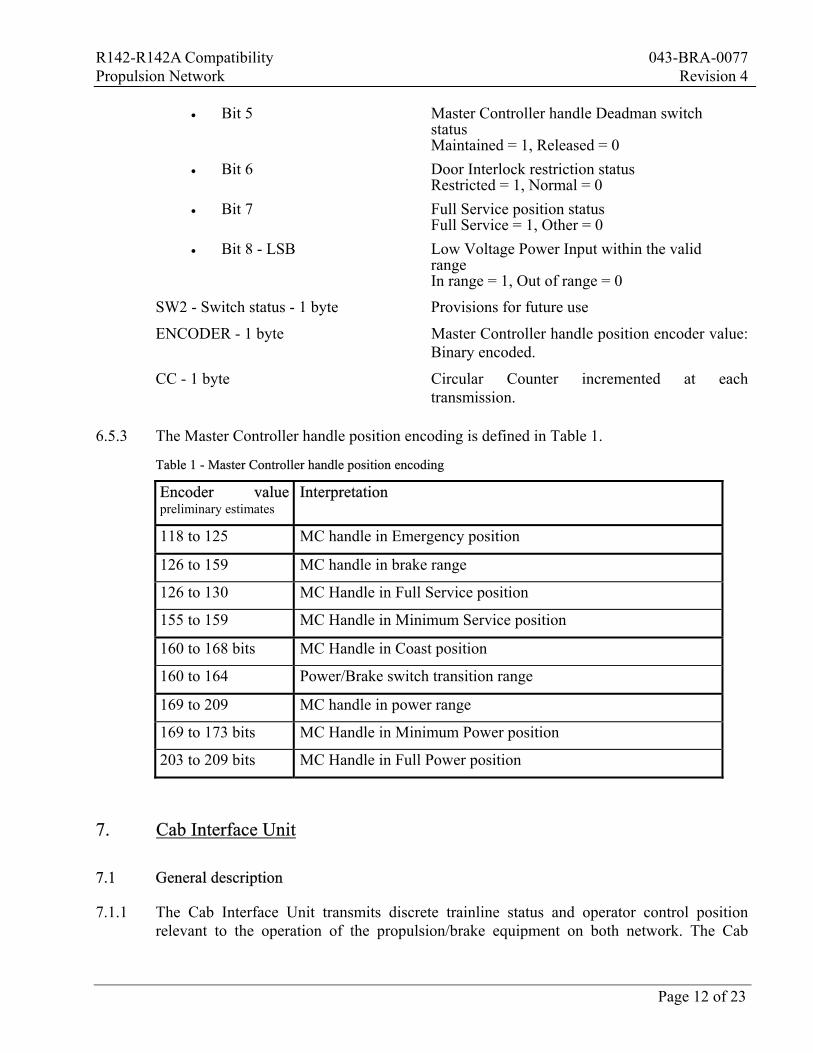
• Bit 5 Master Controller handle Deadman switch status Maintained = 1, Released = 0
• Bit 6 Door Interlock restriction status Restricted = 1, Normal = 0
• Bit 7 Full Service position status Full Service = 1, Other = 0
• Bit 8 - LSB Low Voltage Power Input within the valid range In range = 1, Out of range = 0
SW2 - Switch status - 1 byte Provisions for future use
ENCODER - 1 byte Master Controller handle position encoder value: Binary encoded.
CC - 1 byte Circular Counter incremented at each transmission.
6.5.3 The Master Controller handle position encoding is defined in Table 1.
Table 1 - Master Controller handle position encoding
Encoder value preliminary estimates
Interpretation
118 to 125 MC handle in Emergency position
126 to 159 MC handle in brake range
126 to 130 MC Handle in Full Service position
155 to 159 MC Handle in Minimum Service position
160 to 168 bits MC Handle in Coast position
160 to 164 Power/Brake switch transition range
169 to 209 MC handle in power range
169 to 173 bits MC Handle in Minimum Power position
203 to 209 bits MC Handle in Full Power position
7. Cab Interface Unit
7.1 General description
7.1.1 The Cab Interface Unit transmits discrete trainline status and operator control position relevant to the operation of the propulsion/brake equipment on both network. The Cab
R142-R142A Compatibility 043-BRA-0077 Propulsion Network Revision 4
Page 13 of 23
Interface Unit shall be built from two electrically independent units that each send information on its respective Propulsion Network. The Cab Interface Unit is powered from the Master Controller Key and is turned on when its corresponding Master Controller is keyed-in, thus preventing the issuance of any message when its Master Controller is inactive.
7.1.2 The Cab Interface Unit shall essentially converts the electrical signal received from various digital signals into LON network compatible signals. Each Propulsion Network LON interface of the Cab Interface Unit shall transmit the status of its various input on the network without any interpretation or processing of the signals.
7.2 Transmitted information
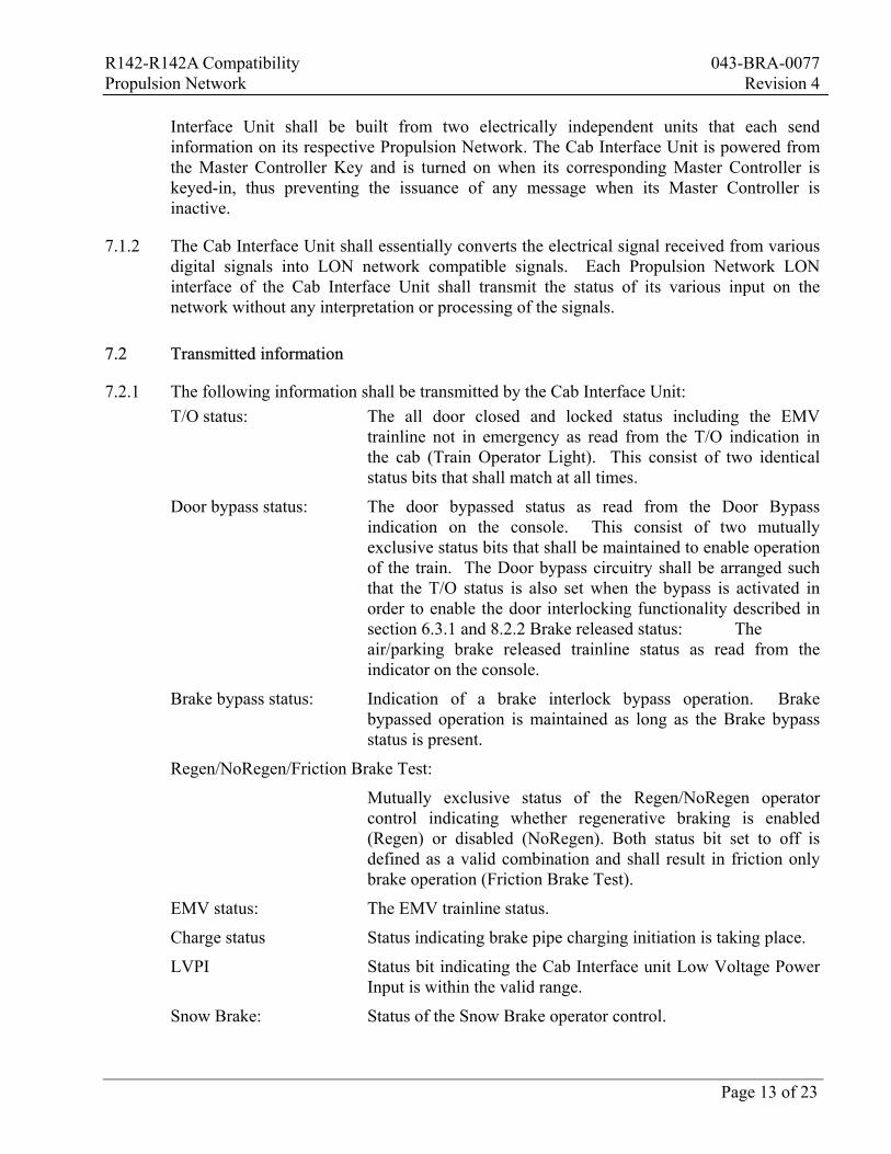
7.2.1 The following information shall be transmitted by the Cab Interface Unit: T/O status: The all door closed and locked status including the EMV
trainline not in emergency as read from the T/O indication in the cab (Train Operator Light). This consist of two identical status bits that shall match at all times.
Door bypass status: The door bypassed status as read from the Door Bypass indication on the console. This consist of two mutually exclusive status bits that shall be maintained to enable operation of the train. The Door bypass circuitry shall be arranged such that the T/O status is also set when the bypass is activated in order to enable the door interlocking functionality described in section 6.3.1 and 8.2.2 Brake released status: The air/parking brake released trainline status as read from the indicator on the console.
Brake bypass status: Indication of a brake interlock bypass operation. Brake bypassed operation is maintained as long as the Brake bypass status is present.
Regen/NoRegen/Friction Brake Test:
Mutually exclusive status of the Regen/NoRegen operator control indicating whether regenerative braking is enabled (Regen) or disabled (NoRegen). Both status bit set to off is defined as a valid combination and shall result in friction only brake operation (Friction Brake Test).
EMV status: The EMV trainline status.
Charge status Status indicating brake pipe charging initiation is taking place.
LVPI Status bit indicating the Cab Interface unit Low Voltage Power Input is within the valid range.
Snow Brake: Status of the Snow Brake operator control.
R142-R142A Compatibility 043-BRA-0077 Propulsion Network Revision 4
Page 14 of 23
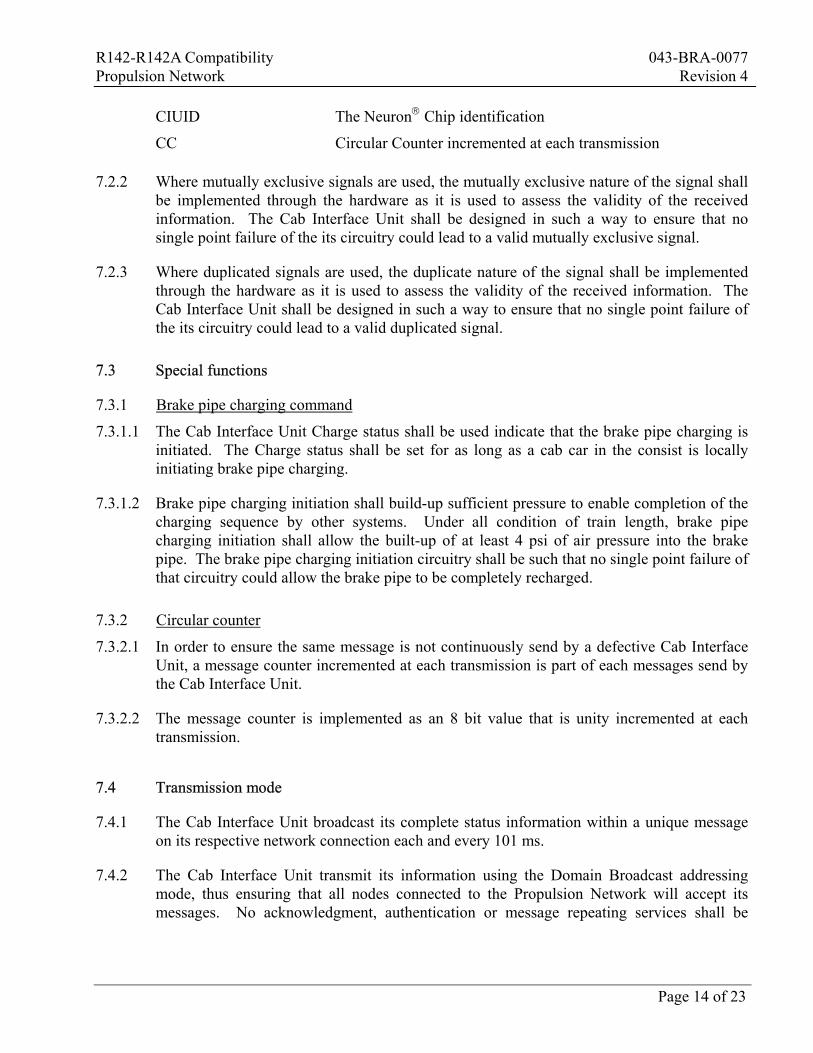
CIUID The Neuron Chip identification
CC Circular Counter incremented at each transmission
7.2.2 Where mutually exclusive signals are used, the mutually exclusive nature of the signal shall be implemented through the hardware as it is used to assess the validity of the received information. The Cab Interface Unit shall be designed in such a way to ensure that no single point failure of the its circuitry could lead to a valid mutually exclusive signal.
7.2.3 Where duplicated signals are used, the duplicate nature of the signal shall be implemented through the hardware as it is used to assess the validity of the received information. The Cab Interface Unit shall be designed in such a way to ensure that no single point failure of the its circuitry could lead to a valid duplicated signal.
7.3 Special functions
7.3.1 Brake pipe charging command
7.3.1.1 The Cab Interface Unit Charge status shall be used indicate that the brake pipe charging is initiated. The Charge status shall be set for as long as a cab car in the consist is locally initiating brake pipe charging.
7.3.1.2 Brake pipe charging initiation shall build-up sufficient pressure to enable completion of the charging sequence by other systems. Under all condition of train length, brake pipe charging initiation shall allow the built-up of at least 4 psi of air pressure into the brake pipe. The brake pipe charging initiation circuitry shall be such that no single point failure of that circuitry could allow the brake pipe to be completely recharged.
7.3.2 Circular counter
7.3.2.1 In order to ensure the same message is not continuously send by a defective Cab Interface Unit, a message counter incremented at each transmission is part of each messages send by the Cab Interface Unit.
7.3.2.2 The message counter is implemented as an 8 bit value that is unity incremented at each transmission.
7.4 Transmission mode
7.4.1 The Cab Interface Unit broadcast its complete status information within a unique message on its respective network connection each and every 101 ms.
7.4.2 The Cab Interface Unit transmit its information using the Domain Broadcast addressing mode, thus ensuring that all nodes connected to the Propulsion Network will accept its messages. No acknowledgment, authentication or message repeating services shall be
R142-R142A Compatibility 043-BRA-0077 Propulsion Network Revision 4
Page 15 of 23
required from the network in order to minimize the number of information packet transiting on the Propulsion Network.
7.4.3 In order to avoid possible repeated collision with other messages from other systems and to benefit from the p-persistent CSMA algorithm of the LonTalk® protocol, no priority assignment are made to the Cab Interface Unit messages.
7.4.4 The Cab Interface Unit message is assigned the message number 01h (message table information).
7.4.5 The Cab Interface Unit Propulsion Network LON interface are each assigned a node and group number as follow: • LON interface on the RS Propulsion Network: Node = 3, Group = 1 • LON interface on the LS Propulsion Network: Node = 3, Group = 1
7.5 Message format
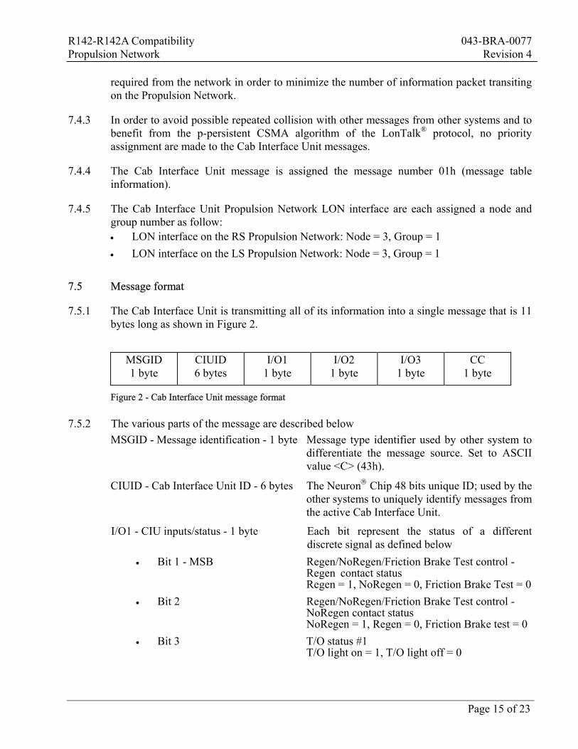
7.5.1 The Cab Interface Unit is transmitting all of its information into a single message that is 11 bytes long as shown in Figure 2.
MSGID 1 byte
CIUID 6 bytes
I/O1 1 byte
I/O2 1 byte
I/O3 1 byte
CC 1 byte
Figure 2 - Cab Interface Unit message format
7.5.2 The various parts of the message are described below MSGID - Message identification - 1 byte Message type identifier used by other system to
differentiate the message source. Set to ASCII value <C> (43h).
CIUID - Cab Interface Unit ID - 6 bytes The Neuron Chip 48 bits unique ID; used by the other systems to uniquely identify messages from the active Cab Interface Unit.
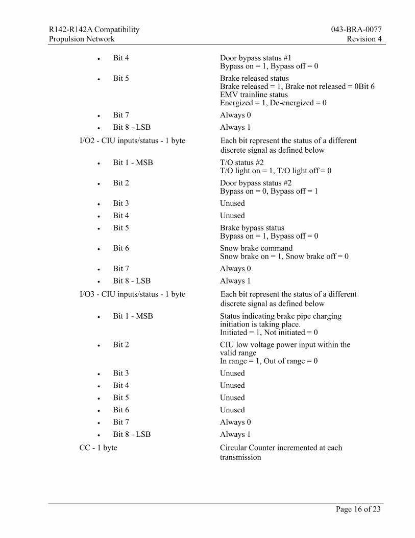
I/O1 - CIU inputs/status - 1 byte Each bit represent the status of a different discrete signal as defined below
• Bit 1 - MSB Regen/NoRegen/Friction Brake Test control - Regen contact status Regen = 1, NoRegen = 0, Friction Brake Test = 0
• Bit 2 Regen/NoRegen/Friction Brake Test control - NoRegen contact status NoRegen = 1, Regen = 0, Friction Brake test = 0
• Bit 3 T/O status #1 T/O light on = 1, T/O light off = 0
R142-R142A Compatibility 043-BRA-0077 Propulsion Network Revision 4
Page 16 of 23
• Bit 4 Door bypass status #1 Bypass on = 1, Bypass off = 0
• Bit 5 Brake released status Brake released = 1, Brake not released = 0Bit 6 EMV trainline status Energized = 1, De-energized = 0
• Bit 7 Always 0 • Bit 8 - LSB Always 1
I/O2 - CIU inputs/status - 1 byte Each bit represent the status of a different discrete signal as defined below
• Bit 1 - MSB T/O status #2 T/O light on = 1, T/O light off = 0
• Bit 2 Door bypass status #2 Bypass on = 0, Bypass off = 1
• Bit 3 Unused • Bit 4 Unused • Bit 5 Brake bypass status
Bypass on = 1, Bypass off = 0 • Bit 6 Snow brake command
Snow brake on = 1, Snow brake off = 0 • Bit 7 Always 0 • Bit 8 - LSB Always 1
I/O3 - CIU inputs/status - 1 byte Each bit represent the status of a different discrete signal as defined below
• Bit 1 - MSB Status indicating brake pipe charging initiation is taking place. Initiated = 1, Not initiated = 0
• Bit 2 CIU low voltage power input within the valid range In range = 1, Out of range = 0
• Bit 3 Unused • Bit 4 Unused • Bit 5 Unused • Bit 6 Unused • Bit 7 Always 0 • Bit 8 - LSB Always 1
CC - 1 byte Circular Counter incremented at each transmission
R142-R142A Compatibility 043-BRA-0077 Propulsion Network Revision 4
Page 17 of 23
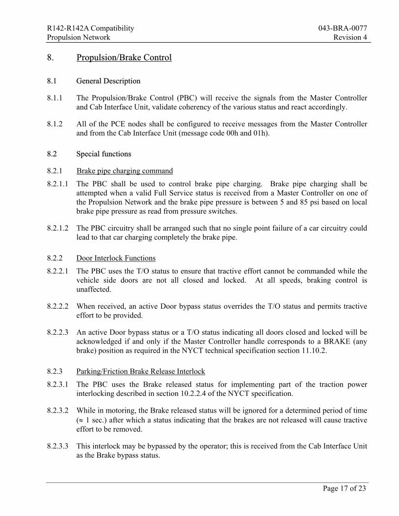
8. Propulsion/Brake Control
8.1 General Description
8.1.1 The Propulsion/Brake Control (PBC) will receive the signals from the Master Controller and Cab Interface Unit, validate coherency of the various status and react accordingly.
8.1.2 All of the PCE nodes shall be configured to receive messages from the Master Controller and from the Cab Interface Unit (message code 00h and 01h).
8.2 Special functions
8.2.1 Brake pipe charging command
8.2.1.1 The PBC shall be used to control brake pipe charging. Brake pipe charging shall be attempted when a valid Full Service status is received from a Master Controller on one of the Propulsion Network and the brake pipe pressure is between 5 and 85 psi based on local brake pipe pressure as read from pressure switches.
8.2.1.2 The PBC circuitry shall be arranged such that no single point failure of a car circuitry could lead to that car charging completely the brake pipe.
8.2.2 Door Interlock Functions
8.2.2.1 The PBC uses the T/O status to ensure that tractive effort cannot be commanded while the vehicle side doors are not all closed and locked. At all speeds, braking control is unaffected.
8.2.2.2 When received, an active Door bypass status overrides the T/O status and permits tractive effort to be provided.
8.2.2.3 An active Door bypass status or a T/O status indicating all doors closed and locked will be acknowledged if and only if the Master Controller handle corresponds to a BRAKE (any brake) position as required in the NYCT technical specification section 11.10.2.
8.2.3 Parking/Friction Brake Release Interlock
8.2.3.1 The PBC uses the Brake released status for implementing part of the traction power interlocking described in section 10.2.2.4 of the NYCT specification.
8.2.3.2 While in motoring, the Brake released status will be ignored for a determined period of time (≈ 1 sec.) after which a status indicating that the brakes are not released will cause tractive effort to be removed.
8.2.3.3 This interlock may be bypassed by the operator; this is received from the Cab Interface Unit as the Brake bypass status.
R142-R142A Compatibility 043-BRA-0077 Propulsion Network Revision 4
Page 18 of 23
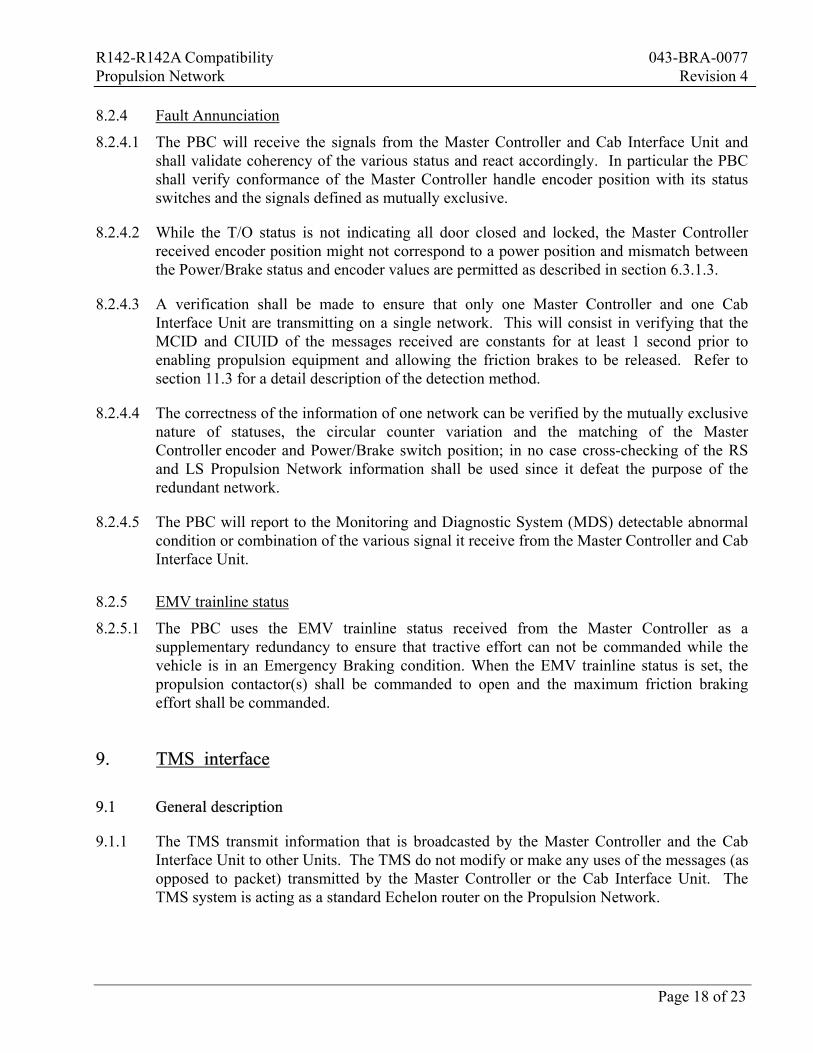
8.2.4 Fault Annunciation
8.2.4.1 The PBC will receive the signals from the Master Controller and Cab Interface Unit and shall validate coherency of the various status and react accordingly. In particular the PBC shall verify conformance of the Master Controller handle encoder position with its status switches and the signals defined as mutually exclusive.
8.2.4.2 While the T/O status is not indicating all door closed and locked, the Master Controller received encoder position might not correspond to a power position and mismatch between the Power/Brake status and encoder values are permitted as described in section 6.3.1.3.
8.2.4.3 A verification shall be made to ensure that only one Master Controller and one Cab Interface Unit are transmitting on a single network. This will consist in verifying that the MCID and CIUID of the messages received are constants for at least 1 second prior to enabling propulsion equipment and allowing the friction brakes to be released. Refer to section 11.3 for a detail description of the detection method.
8.2.4.4 The correctness of the information of one network can be verified by the mutually exclusive nature of statuses, the circular counter variation and the matching of the Master Controller encoder and Power/Brake switch position; in no case cross-checking of the RS and LS Propulsion Network information shall be used since it defeat the purpose of the redundant network.
8.2.4.5 The PBC will report to the Monitoring and Diagnostic System (MDS) detectable abnormal condition or combination of the various signal it receive from the Master Controller and Cab Interface Unit.
8.2.5 EMV trainline status
8.2.5.1 The PBC uses the EMV trainline status received from the Master Controller as a supplementary redundancy to ensure that tractive effort can not be commanded while the vehicle is in an Emergency Braking condition. When the EMV trainline status is set, the propulsion contactor(s) shall be commanded to open and the maximum friction braking effort shall be commanded.
9. TMS interface
9.1 General description
9.1.1 The TMS transmit information that is broadcasted by the Master Controller and the Cab Interface Unit to other Units. The TMS do not modify or make any uses of the messages (as opposed to packet) transmitted by the Master Controller or the Cab Interface Unit. The TMS system is acting as a standard Echelon router on the Propulsion Network.
R142-R142A Compatibility 043-BRA-0077 Propulsion Network Revision 4
Page 19 of 23
9.1.2 The TMS will be configure to pass through only the messages that are send as Domain Broadcast, by being configured with empty Group and Subnet tables (forward no messages).
10. Propulsion Network configuration
10.1 Timing requirements
10.1.1 The configuration and utilization of the Propulsion Network on the R142 and R142A Unit shall be such that it ensure that within any 49ms time slot, a Master Controller message is transmitted and that within any 101ms time slot, a Cab Interface Unit message is transmitted (deterministic requirement).
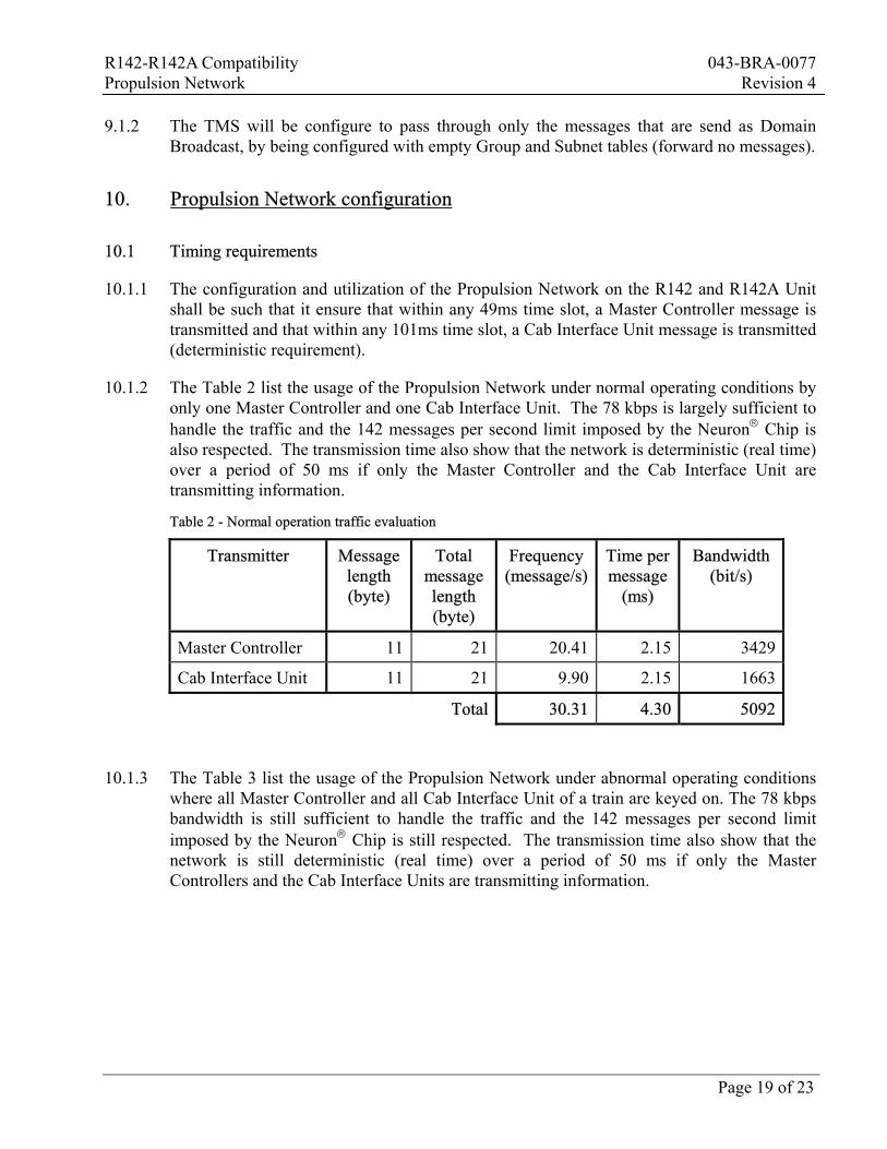
10.1.2 The Table 2 list the usage of the Propulsion Network under normal operating conditions by only one Master Controller and one Cab Interface Unit. The 78 kbps is largely sufficient to handle the traffic and the 142 messages per second limit imposed by the Neuron Chip is also respected. The transmission time also show that the network is deterministic (real time) over a period of 50 ms if only the Master Controller and the Cab Interface Unit are transmitting information.
Table 2 - Normal operation traffic evaluation
Transmitter Message length (byte)
Total message length (byte)
Frequency(message/s)
Time per message
(ms)
Bandwidth(bit/s)
Master Controller 11 21 20.41 2.15 3429
Cab Interface Unit 11 21 9.90 2.15 1663
Total 30.31 4.30 5092
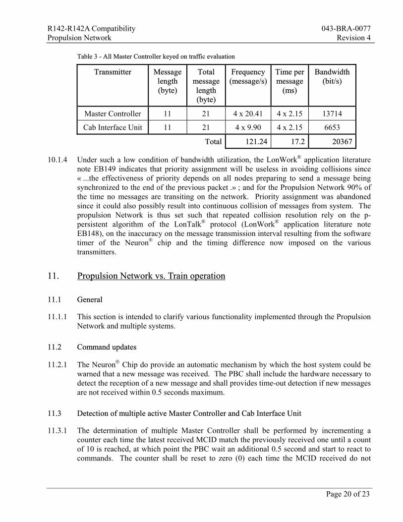
10.1.3 The Table 3 list the usage of the Propulsion Network under abnormal operating conditions where all Master Controller and all Cab Interface Unit of a train are keyed on. The 78 kbps bandwidth is still sufficient to handle the traffic and the 142 messages per second limit imposed by the Neuron Chip is still respected. The transmission time also show that the network is still deterministic (real time) over a period of 50 ms if only the Master Controllers and the Cab Interface Units are transmitting information.
R142-R142A Compatibility 043-BRA-0077 Propulsion Network Revision 4
Page 20 of 23
Table 3 - All Master Controller keyed on traffic evaluation
Transmitter Message length (byte)
Total message length (byte)
Frequency(message/s)
Time per message
(ms)
Bandwidth(bit/s)
Master Controller 11 21 4 x 20.41 4 x 2.15 13714
Cab Interface Unit 11 21 4 x 9.90 4 x 2.15 6653
Total 121.24 17.2 20367
10.1.4 Under such a low condition of bandwidth utilization, the LonWork® application literature note EB149 indicates that priority assignment will be useless in avoiding collisions since « ...the effectiveness of priority depends on all nodes preparing to send a message being synchronized to the end of the previous packet .» ; and for the Propulsion Network 90% of the time no messages are transiting on the network. Priority assignment was abandoned since it could also possibly result into continuous collision of messages from system. The propulsion Network is thus set such that repeated collision resolution rely on the p-persistent algorithm of the LonTalk® protocol (LonWork® application literature note EB148), on the inaccuracy on the message transmission interval resulting from the software timer of the Neuron® chip and the timing difference now imposed on the various transmitters.
11. Propulsion Network vs. Train operation
11.1 General
11.1.1 This section is intended to clarify various functionality implemented through the Propulsion Network and multiple systems.
11.2 Command updates
11.2.1 The Neuron Chip do provide an automatic mechanism by which the host system could be warned that a new message was received. The PBC shall include the hardware necessary to detect the reception of a new message and shall provides time-out detection if new messages are not received within 0.5 seconds maximum.
11.3 Detection of multiple active Master Controller and Cab Interface Unit
11.3.1 The determination of multiple Master Controller shall be performed by incrementing a counter each time the latest received MCID match the previously received one until a count of 10 is reached, at which point the PBC wait an additional 0.5 second and start to react to commands. The counter shall be reset to zero (0) each time the MCID received do not
R142-R142A Compatibility 043-BRA-0077 Propulsion Network Revision 4
Page 21 of 23
match the previous one received, which in turns shall inhibit the PBC form responding to commands and shall indicate that more than one Master controller is active.
11.3.2 Multiple active Cab Interface Unit shall be verified with the same logic as the Master Controller, except that a count of 5 (instead of 10 as specified in 11.3.1) shall be reached prior to enabling the PBC.
11.4 Train power-up
11.4.1 Upon powering of the Master Controller its message flow start and the various systems start to react as described previously.
11.4.2 If the Master Controller keyed-in is the first one of a train, the brake pipe is thus discharged and could be commanded to charge normally after the 1.1 second delay (6 Cab Interface Unit messages +0.5 second delay) required for the detection of multiple active Master Controller and Cab Interface Unit described in section 11.3.
11.4.3 If the Master Controller keyed-in is not the first one of a train, the Master Controller circuitry connection shall ensure that an Emergency Brake condition is created, forcing the brake pipe to discharged and stopping a train that could have been in motion. The detection of multiple active Master Controller and Cab Interface Unit described in section shall 11.3 then apply and prevent PBC from charging the Brake Pipe.
11.4.4 The brake pipe charging is inhibited as per the functionality required in section 7.3.1, 8.2.1 and 11.3.
11.5 PBC reaction to static circular counter values
11.5.1 The PBC received commands from the Master Controller and from the Cab Interface Unit shall be considered valid when the circular counter value included within the message are changing. If the circular counter value received on one side of the network are not changing for more than 0.5 seconds then the PBC shall no longer respond to the commands of that network and shall attempt to use the other side of the network.
11.5.2 Refer to section 11.9 for faulty network situation.
11.6 PBC reaction to invalid Master Controller information
11.6.1 The PBC received commands from the Master Controller shall conform to the format and content defined in section 6. If erroneous information is received then the PBC shall no longer respond to the commands received on that network and shall attempt to use the other side of the network.
11.6.2 Refer to section 11.9 for faulty network situation.
R142-R142A Compatibility 043-BRA-0077 Propulsion Network Revision 4
Page 22 of 23
11.7 PBC reaction to invalid Cab Interface Unit information
11.7.1 The PBC received commands from the Cab Interface Unit shall conform to the format and content defined in section 7. If erroneous information is received then the PBC shall no longer respond to the commands received on that network and shall attempt to use the other side of the network.
11.7.2 Refer to section 11.9 for faulty network situation.
11.8 Propulsion response time
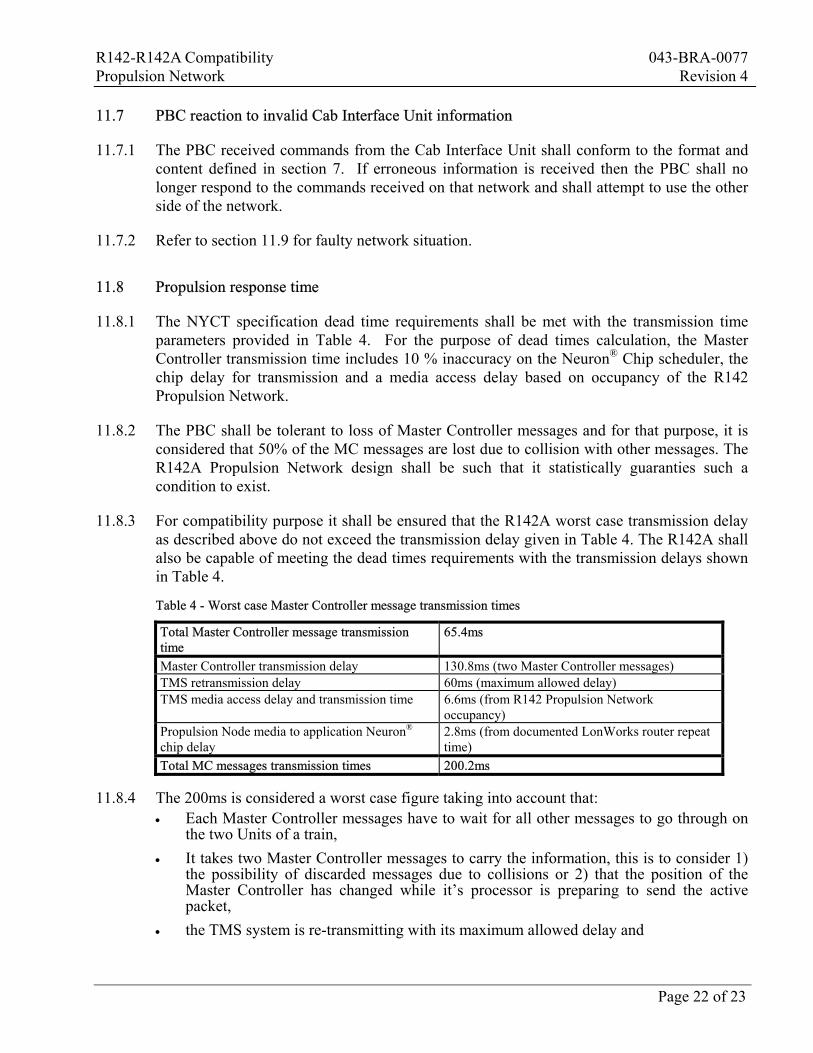
11.8.1 The NYCT specification dead time requirements shall be met with the transmission time parameters provided in Table 4. For the purpose of dead times calculation, the Master Controller transmission time includes 10 % inaccuracy on the Neuron® Chip scheduler, the chip delay for transmission and a media access delay based on occupancy of the R142 Propulsion Network.
11.8.2 The PBC shall be tolerant to loss of Master Controller messages and for that purpose, it is considered that 50% of the MC messages are lost due to collision with other messages. The R142A Propulsion Network design shall be such that it statistically guaranties such a condition to exist.
11.8.3 For compatibility purpose it shall be ensured that the R142A worst case transmission delay as described above do not exceed the transmission delay given in Table 4. The R142A shall also be capable of meeting the dead times requirements with the transmission delays shown in Table 4.
Table 4 - Worst case Master Controller message transmission times
Total Master Controller message transmission time
65.4ms
Master Controller transmission delay 130.8ms (two Master Controller messages) TMS retransmission delay 60ms (maximum allowed delay) TMS media access delay and transmission time 6.6ms (from R142 Propulsion Network
occupancy) Propulsion Node media to application Neuron® chip delay
2.8ms (from documented LonWorks router repeat time)
Total MC messages transmission times 200.2ms
11.8.4 The 200ms is considered a worst case figure taking into account that: • Each Master Controller messages have to wait for all other messages to go through on
the two Units of a train, • It takes two Master Controller messages to carry the information, this is to consider 1)
the possibility of discarded messages due to collisions or 2) that the position of the Master Controller has changed while it’s processor is preparing to send the active packet,
• the TMS system is re-transmitting with its maximum allowed delay and
R142-R142A Compatibility 043-BRA-0077 Propulsion Network Revision 4
Page 23 of 23
• The Neuron® chip of the nodes are not any faster than a router (1 x 6 layers vs. 2 x 6 layers to go through).
11.8.5 The above calculations describes a realistic worst case transmission time. Under normal operating conditions it is statistically possible that the transmission times be exceeded due to the non deterministic and asynchronous nature of the Network.
11.9 Faulty Networks
11.9.1 In normal operation the PBC will only react to the commands from only one network. This network is referred to as the active network. At power-up, the PBC shall select a network and define it as the active network, and change to the other network when a fault has been detected on the active network.
11.9.2 If the active network is considered to have failed, or have some failed transmitting equipment then the PBC shall swap networks.
11.9.3 Once a network has failed, all data from that failed network will be ignored and it will be considered as failed until the next emergency brake application (as sensed by a brake pipe pressure switch) OR the other network has also failed. Only then may the failed network be checked (not necessarily swapped to) and the fault cleared if the data checks show that the network is functional.
11.9.4 In the event that both networks are considered to have failed then the PBC shall consider all the demands as for “coast”, except that the existing brake demand shall remain unchanged.