Embed Size (px)
Citation preview
New Unit Information
New Unit Information 07.2006
BR/BD 55/40BR/BD 45/40
1.533-...
5.906-270
New Unit Information 07.2006
Contents BR/BD 55/40 45/40 C Ep, C Bp, W Bp Pack
Page 2 / 60
Contents
1 Equipment features ............................................................................................. 4-81.1 Technical features ...................................................................................................41.2 View from the front ............................................................................................... 5-61.3 Rear view.................................................................................................................71.4 Cleaning agent compartment ...................................................................................8
2 Unit function (Bp only) ...................................................................................... 9-322.1 Battery (G1) (Bp Pack only) .................................................................................... 92.2 Cleaning agent pump (M4) (W Bp Pack only, C Bp Pack option) .........................102.3 Control panel (Bp only) .................................................................................... 11-132.4 Operator presence control handle, brush motor (Bp only) .................................... 142.5 Drive system (W Bp Pack only) ............................................................................152.6 Main control printed circuit board (A1) (Bp only) ............................................. 16-172.7 Battery charger (U1) (Bp Pack only)............................................................... 18-192.8 Operator functions (W Bp Pack) .................................................................. 20-262.8.1 Initial operation - drive (W Bp Pack) ......................................................................202.8.2 Wet scrubbing (with vacuuming) (W Bp Pack) .....................................................212.8.3 Wet scrubbing (without vacuuming) (W Bp Pack) ................................................ 222.8.4 Vacuuming (without scrubbing mode) (W Bp Pack) .............................................232.8.5 Polishing (without vacuuming) (W Bp Pack) ......................................................... 242.8.6 Polishing (with vacuuming) (W Bp Pack) .............................................................. 252.8.7 Parameter assignment (W Bp Pack) .....................................................................262.9 Operator functions (C Bp / C Bp Pack) ....................................................... 27-322.9.1 Initial operation - off mode (C Bp / C Bp Pack)...................................................... 272.9.2 Wet scrubbing (with vacuuming) (C Bp / C Bp Pack) ........................................... 282.9.3 Wet scrubbing (without vacuuming) (C Bp / C Bp Pack) ...................................... 292.9.4 Vacuuming (without scrubbing mode) (C Bp / C Bp Pack) ...................................302.9.5 Polishing (without vacuuming) (C Bp / C Bp Pack) ............................................... 312.9.6 Polishing (with vacuuming) (C Bp / C Bp Pack) ....................................................322.10 Manufacture settings .............................................................................................332.11 Setup menu .................................................................................................... 34-362.11.1 Access to the setup menu (W Bp Pack) ...............................................................342.11.2 Saving in the setup menu (W Bp Pack) ................................................................ 352.11.3 Setup menu display (W Bp Pack) .........................................................................36
3 Unit function (Ep only) ....................................................................................37-403.1 Chassis (Ep only) .................................................................................................. 373.2 Control panel (Ep only) .................................................................................... 38-393.3 Unit switch with motor protection switch (Q1) (Ep only) .......................................40

New Unit Information 07.2006
BR/BD 55/40 45/40 C Ep, C Bp, W Bp Pack Contents
Page 3 / 60
Contents
4 Unit function (all versions) ..............................................................................41-534.1 Contact pressure adjustment (BD version only) ...................................................414.2 Transport roller ...................................................................................................... 424.3 Brush head ...................................................................................................... 43-444.4 Brush drive assembly ...................................................................................... 45-464.5 Solenoid valve, water stop (Y1) .............................................................................474.6 Tank cover, view from inside................................................................................. 484.7 Dirty water tank .....................................................................................................494.8 Suction motor (M2) ................................................................................................504.9 Freshwater and dirty water tank ...................................................................... 51-53
5 Circuit diagrams ..............................................................................................54-565.1 BR/BD 55/40, 45/40 C Ep (Circuit diagram 0.088-845) .........................................545.2 BR/BD 55/40, 45/40 C Bp (Circuit diagram 0.088-843) .........................................555.3 BR/BD 55/40, 45/40 C Bp Pack / W Bp Pack (Circuit diagram 0.088-844) ..........56
6 Replacement times ............................................................................................... 576.1 BR version replacement times: .............................................................................576.2 BD version replacement times .............................................................................. 57
7 Troubleshooting ..............................................................................................58-597.1 Troubleshooting without displays .......................................................................... 587.2 Troubleshooting with displays (W Bp Pack only) .................................................. 59
8 Technical specifications ...................................................................................... 60
9 Special tool ........................................................................................................... 60
10 Tightening torque ................................................................................................. 60

New Unit Information 07.2006
Equipment features BR/BD 55/40 45/40 C Ep, C Bp, W Bp Pack
Page 4 / 60
General Information
– The unit is the successor to the BR/BD 530.
– Abbreviations:
Ep = Mains powered
Bp = Battery powered
Bp Pack = Battery powered with integratedcharger
C = Compact (without drive system)
W = Walk behind (Bp Pack only)
Drive system (W Bp Pack only)
– 24 V 130 watt electric motor with freewheelingfunction.
– Oil resistant wheels.
– Transport roller extended/retracted using footpedal:
– for relieving the brush rollers after finishingthe work.
– for unit transport.
Brush system
BR version:
– BR brush head with brush quick-changesystem.
– 2 brush rollers, effective working width 550m m(BR 55/40), and 450 mm (BR 45/40).
– Brush drive assembly system with toothedbelt (similar to BR Vario).
BD version:
– 1 disc brush with quick-change system.
– Brush drive assembly system with toothedbelt (similar to BR 530).
Vacuum system
– Suction motor(Bp = BR/BD 530, Ep = BR/BD 40/25).
– Mechanical float.
– Suction bar, straight version only.
– Suction bar is lowered/raised manually.
Brush drive assembly
– 24 V electric motor.
Water system
– No water pump, the water flows to the brushhead by gravity.
– Water volume control through ball valve (similarto BR/BD 530).
– Automatic water stop when brush stops dueto solenoid valve water stop(= BR/BD 40/25 C).
– Level indicator of the freshwater tank.
– Tank-in-tank system (2-piece).
– Freshwater tank (40 l).
– Dirty water tank (40 l).
Electrics
Ep version:
– Operator presence control handle (similar toBR/BD 40/25 Ep).
– 6-stage program selection switch (mechanicaldecoding switch).
Bp version:
– Indicator lamp, battery monitoring.
– Indicator lamp, fault.
– FACT rpm adjustment. 3 adjustment levels(Power/Whisper/Fine), manufacture setting:Power.
– Clean Speed adjustment, 5 adjustment levels(20% - 100%), manufacturer setting 60%.
– Operator presence control handle withmicroswitch (= BR/BD 530).
– 6-stage program selection switch (mechanicaldecoding switch).
– Integrated charger (Bp Pack only).
– Batteries 100 Ah, maintenance free (Bp Packonly).
– Charger 230 V, 15 A (± 10%), IUIacharacteristic curve (Bp Pack only).
– Standby mode, switches off after 30 minutes.
1.1 Technical features
New Unit Information 07.2006
BR/BD 55/40 45/40 C Ep, C Bp, W Bp Pack Equipment features
Page 5 / 60
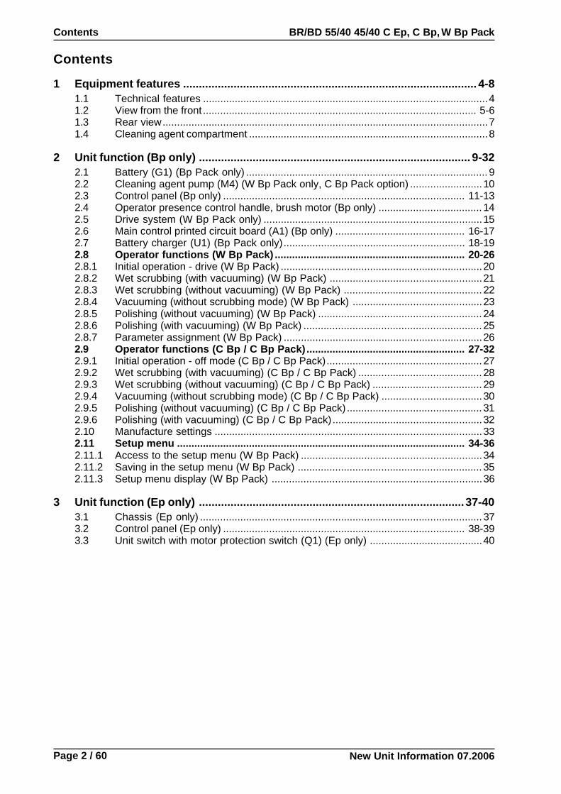
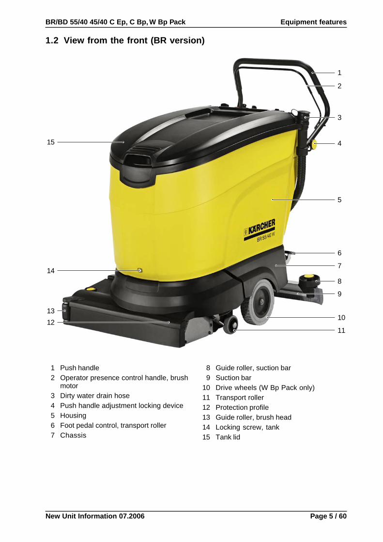
1.2 View from the front (BR version)
1 Push handle2 Operator presence control handle, brush
motor3 Dirty water drain hose4 Push handle adjustment locking device5 Housing6 Foot pedal control, transport roller7 Chassis
1
2
3
8
9
10
14
13
12
15 4
5
6
11
7
8 Guide roller, suction bar9 Suction bar
10 Drive wheels (W Bp Pack only)11 Transport roller12 Protection profile13 Guide roller, brush head14 Locking screw, tank15 Tank lid

New Unit Information 07.2006
Equipment features BR/BD 55/40 45/40 C Ep, C Bp, W Bp Pack
Page 6 / 60
1.2 View from the front (BD version)
1 Push handle2 Operator presence control handle, brush
motor3 Dirty water drain hose4 Push handle adjustment locking device5 Housing6 Foot pedal control, transport roller7 Chassis
1
2
3
8
9
10
14
13
154
5
6
11
7
8 Guide roller, suction bar9 Suction bar
10 Drive wheels (W Bp Pack only)11 Transport roller12 Disc brush13 Guide roller, brush head14 Locking screw, tank15 Tank lid
12

New Unit Information 07.2006
BR/BD 55/40 45/40 C Ep, C Bp, W Bp Pack Equipment features
Page 7 / 60
1.3 Rear view
4
5
7
6
1918 2
1
31716
15
14
13
11
10
8
9
12
1 EMERGENCY STOP button (S1)(W Bp Pack only)
2 Adjustment, water volume metering valve3 Switch, cleaning agent (S5)
(W Bp Pack only, C Bp Pack option)4 Level indicator, freshwater tank5 Adjusting rod, water volume metering
valve6 Fresh water tank7 Water volume metering valve8 Rubber strip9 Wing screws, suction bar tilt adjustment
10 Suction bar11 Guide roller, suction bar
12 Suction hose13 Foot pedal control, transport roller14 Lever, lower/raise suction bar15 Cleaning agent compartment16 Key switch (S0) (W Bp Pack only)17 Program selection switch (S1, Ep) (S2,
Bp)18 Info button, rotary and inching function
(W Bp Pack only)19 Switch, drive motor (S4)
(W Bp Pack only)

New Unit Information 07.2006
Equipment features BR/BD 55/40 45/40 C Ep, C Bp, W Bp Pack
Page 8 / 60
1.4 Cleaning agent compartment
2
1
1 Cleaning agent compartment (fold-outand removable)
2 Cleaning agent tank (accessory)3 Filler cap with vent pipe and ball-type
check valve4 Vent pipe5 Ball-type check valve6 Cap, vent pipe (slit)7 Connection, cleaning agent hose8 Connection, cleaning agent tank
ventilation
3
4
8
7
5
4
3
4
6
3
Connections, cleaning agentcompartment
Filler cap, cleaningagent tank
Filler cap with vent pipe and slitted cap.

New Unit Information 07.2006
BR/BD 55/40 45/40 C Ep, C Bp, W Bp Pack Unit function (Bp only)
Page 9 / 60
2.1 Battery (G1) (Bp Pack only)
1 Battery (G1) (2x)2 Solenoid valve, water stop (Y1)3 Freshwater inlet hose4 Battery (G1) (+ post)5 Battery (G1) (- post)6 Fuse (F1) for battery (G1) (+ post)
+
–5
+–
14
2
+6
3
New Unit Information 07.2006
Unit function (Bp only) BR/BD 55/40 45/40 C Ep, C Bp, W Bp Pack
Page 10 / 60
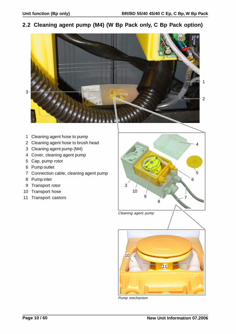
2.2 Cleaning agent pump (M4) (W Bp Pack only, C Bp Pack option)
Cleaning agent pump
3
1
2
4
5
6
87
10
1 Cleaning agent hose to pump2 Cleaning agent hose to brush head3 Cleaning agent pump (M4)4 Cover, cleaning agent pump5 Cap, pump rotor6 Pump outlet7 Connection cable, cleaning agent pump8 Pump inlet9 Transport rotor
10 Transport hose11 Transport castors
3
9
Pump mechanism
11
10

New Unit Information 07.2006
BR/BD 55/40 45/40 C Ep, C Bp, W Bp Pack Unit function (Bp only)
Page 11 / 60
2.3 Control panel (Bp only)
R 4 532 6 87 109
12 13 14 15 16 17
1 Switch, drive motor (S4) (W Bp Packonly)
2 Info button, rotary and inching function(W Bp Pack only)
3 Display (W Bp Pack only)4 Indicator lamp, battery monitoring
(red/yellow/green)5 Indicator lamp, fault (red)6 Program selection switch (S2)7 Key switch (S0) (W Bp Pack only)8 EMERGENCY STOP button (S1)
(W Bp Pack only)9 Switch, cleaning agent (S5)
(W Bp Pack only, C Bp Pack option)
10 Adjustment, water volume metering valve11 Position 1 (C Bp): Machine off12 Position 1 (W Bp Pack): Drive
(without cleaning function)13 Position 2: Wet scrubbing
(with vacuuming)14 Position 3: Wet scrubbing
(without vacuuming)15 Position 4: Vacuuming
(without scrubbing mode)16 Position 5: Polishing (without suction)17 Position 6: Polishing (with suction)
13 14 15 16 1711
Program selection switch C Bp Program selection switch W Bp
New Unit Information 07.2006
Unit function (Bp only) BR/BD 55/40 45/40 C Ep, C Bp, W Bp Pack
Page 12 / 60
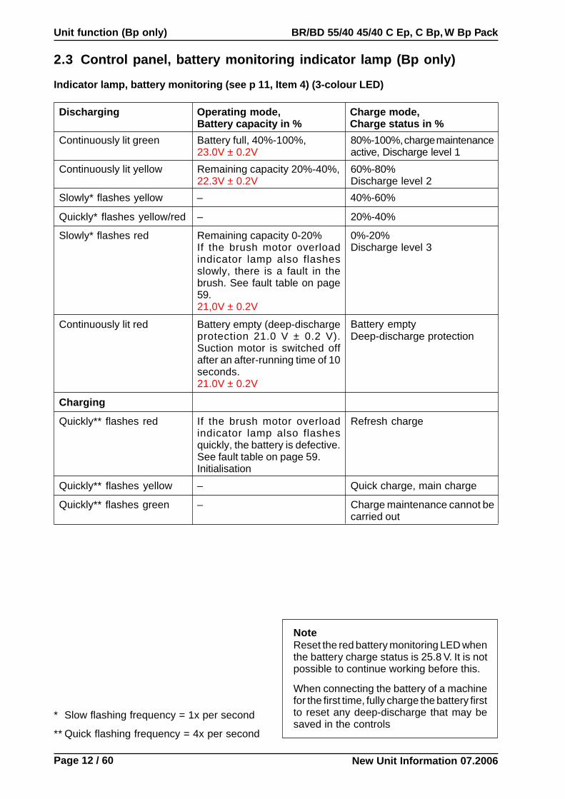
2.3 Control panel, battery monitoring indicator lamp (Bp only)
Discharging Operating mode,Battery capacity in %
Charge mode,Charge status in %
Continuously lit green Battery full, 40%-100%,23.0V ± 0.2V
80%-100%, charge maintenanceactive, Discharge level 1
Indicator lamp, battery monitoring (see p 11, Item 4) (3-colour LED)
NoteReset the red battery monitoring LED whenthe battery charge status is 25.8 V. It is notpossible to continue working before this.
When connecting the battery of a machinefor the first time, fully charge the battery firstto reset any deep-discharge that may besaved in the controls
* Slow flashing frequency = 1x per second
** Quick flashing frequency = 4x per second
Continuously lit yellow Remaining capacity 20%-40%,22.3V ± 0.2V
60%-80%Discharge level 2
Slowly* flashes yellow – 40%-60%
Quickly* flashes yellow/red – 20%-40%
Slowly* flashes red Remaining capacity 0-20%If the brush motor overloadindicator lamp also flashesslowly, there is a fault in thebrush. See fault table on page59.21,0V ± 0.2V
0%-20%Discharge level 3
Continuously lit red Battery empty (deep-dischargeprotection 21.0 V ± 0.2 V).Suction motor is switched offafter an after-running time of 10seconds.21.0V ± 0.2V
Battery emptyDeep-discharge protection
Charging
Quickly** flashes red If the brush motor overloadindicator lamp also flashesquickly, the battery is defective.See fault table on page 59.Initialisation
Refresh charge
Quickly** flashes yellow – Quick charge, main charge
Quickly** flashes green – Charge maintenance cannot becarried out

New Unit Information 07.2006
BR/BD 55/40 45/40 C Ep, C Bp, W Bp Pack Unit function (Bp only)
Page 13 / 60
2.3 Control panel, view from below (Bp only)
6
2
1
3
45
8
7
1 Key switch (S0) (W Bp Pack only)2 Switch, cleaning agent (S5)
(W Bp Pack only, C Bp Pack option)3 Program selection switch (S2)4 Adjustment, water volume metering valve5 EMERGENCY STOP button (S1) (W Bp
Pack only)6 Indicator lamps, battery monitoring and fault7 Switch, drive motor (S4) (W Bp Pack only)8 Main control printed circuit board (A0), info
button and display module (W Bp Pack only)

New Unit Information 07.2006
Unit function (Bp only) BR/BD 55/40 45/40 C Ep, C Bp, W Bp Pack
Page 14 / 60
2.4 Operator presence control handle, brush motor (Bp only)
4
23
1
1 Connection cable, microswitch2 Microswitch (S3)3 Bracket, microswitch4 Operator presence control handle, brush
motor
3
Microswitch installed

New Unit Information 07.2006
BR/BD 55/40 45/40 C Ep, C Bp, W Bp Pack Unit function (Bp only)
Page 15 / 60
2.5 Drive system (W Bp Pack only)
8
7
10
1
23
9
1
8
7
6
3
4
4
5
2
1 Retaining screws, drive shaft suspension2 Drive shafts3 Drive shaft bearing4 Drive shaft suspension5 Transmission6 Connection cable, drive motor7 Caps8 Drive motor (M3)9 Retaining screws, transmission
10 Carbon brushes, drive motor
Replacing the carbon brushesIf the motor is running badly or producesinsufficient power, the carbon brushes (10) maybe worn.– Unscrew caps (7).– Replace carbon brushes (10).– Screw caps (7) back on.

New Unit Information 07.2006
Unit function (Bp only) BR/BD 55/40 45/40 C Ep, C Bp, W Bp Pack
Page 16 / 60
2.6 Main control printed circuit board (A1) (Bp only)
1
1 Battery charger (U1) (Bp Pack only)2 Terminal strip (X11/A1)3 Terminal strip (X3/A1)4 Terminal strip (X1/A1)5 Terminal strip (X2/A1)6 Terminal strip (X10/A1)7 Terminal strip (X5/A1)8 Connecting plug (X15/A1)9 Connecting plug (X16/A1)
10 Connection (X9/A1)11 Connection (X8/A1)12 Connection (X7/A1)
13 Connection (X6/A1)14 Relay (K2)15 Relay (K1)16 Connecting plug (X12/A1)17 Connecting plug (X14/A1)18 Relay (K3)19 Connecting plug (X13/A1)20 Info button (W Bp Pack only)21 Main control printed circuit board (A0)22 Display (W Bp Pack only)23 Indicator lamps, battery monitoring and
fault
2323
4
5
7
9101112
6
1314
16
15
171819
22
21
20 8

New Unit Information 07.2006
BR/BD 55/40 45/40 C Ep, C Bp, W Bp Pack Unit function (Bp only)
Page 17 / 60
2.6 Main control printed circuit board (A1) (Bp only)
1
2
3
54 6
715
101112
14
16
1718
8
913
1 Terminal strip (X1/A1)2 Terminal strip (X2/A1)3 Terminal strip (X5/A1)4 Connection (X9/A1)5 Connecting plug (X15/A1)6 Connecting plug (X16/A1)7 Connection (X6/A1)8 Relay (K2)9 Relay (K1)
10 Connecting plug (X12/A1)11 Connecting plug (X14/A1)12 Connecting plug (X13/A1)13 Relay (K3)14 Connection (X8/A1)15 Connection (X7/A1)16 Terminal strip (X10/A1)17 Terminal strip (X11/A1)18 Terminal strip (X3/A1)

New Unit Information 07.2006
Unit function (Bp only) BR/BD 55/40 45/40 C Ep, C Bp, W Bp Pack
Page 18 / 60
2.7 Battery charger (U1) (Bp Pack only)
81
2
3
4
567
1 Terminal strip (X7)2 Connecting plug (X4)3 Connecting plug (X5)4 Connecting plug (X3)
5 Connecting plug (X1)6 Connecting plug (X2)7 Fuse (F2)8 Fan wheel, charger
New Unit Information 07.2006
BR/BD 55/40 45/40 C Ep, C Bp, W Bp Pack Unit function (Bp only)
Page 19 / 60
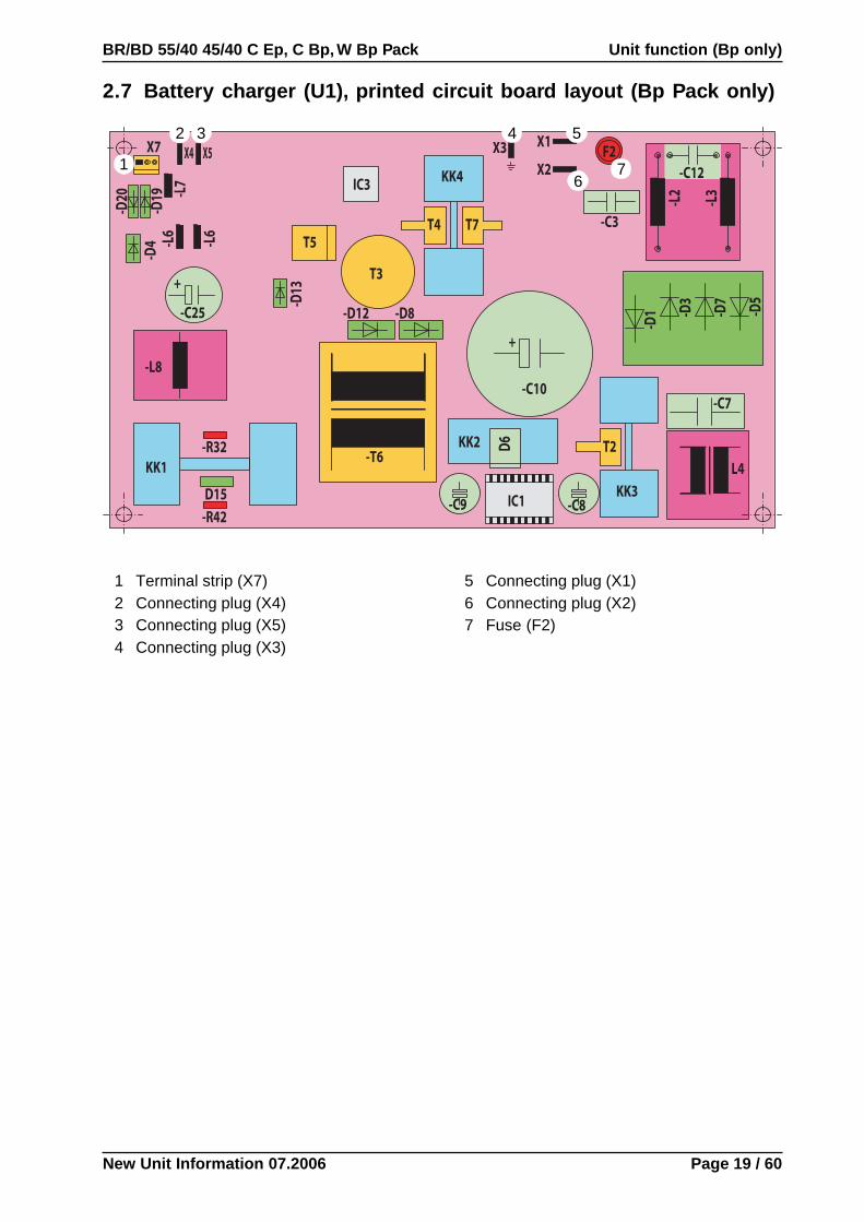
2.7 Battery charger (U1), printed circuit board layout (Bp Pack only)
32
1
4
6
5
7
1 Terminal strip (X7)2 Connecting plug (X4)3 Connecting plug (X5)4 Connecting plug (X3)
5 Connecting plug (X1)6 Connecting plug (X2)7 Fuse (F2)

New Unit Information 07.2006
Unit function (Bp only) BR/BD 55/40 45/40 C Ep, C Bp, W Bp Pack
Page 20 / 60
2.8.1 Initial operation - drive (W Bp Pack)
Switch Program Switch (S2) to „Drive“ position
Display (delayed)Suction delay
Suction motor (M2)active and self test o.k.?
Switch off key switch (S0)
yes
no
DisplayBattery: E...F
Drive motor (M1) ready
Dead man’s switch (S3)actuated?
Drive motor (M3) starts up via startupramp and moves forwards with a
constant speed of 4 km/h.
Release dead man's switch (S3).
Drive motor (M3) is continuouslystopped via brake ramp.
Due to mech free-wheeling, brakeperformance cannot be influenced.
yes
no
Switch on controller (S4)
Switch on key switch (S0)
DisplayBattery: E...F
Self test o.k.?
Dead man’sswitch continiously
actuated?
no
yes
yes
no
DisplayError instructionS
hu
tdo
wn
pre
ced
ure
Init
ial
op
erat
ion
Main relay is engaged
LED (green) active
Main relay is engaged
LED (green) active
DisplayThrottle lever
Note:Driving operation is not possible!!!
Activate operator functions:- Wet scrubbing (Chap 2.8.2 – 2.8.3)- Vacuuming (Chap 2.8.4)- Polishing (Chap 2.8.5 - 2.8.6)- Parameter assignment (Chap 2.8.7)- Manufacture setting (Chap 2.10)
NoteAccess to· Operator function - information menu
see 2.8.7 Parameter assignment
· Parameter setupsee 2.11 Setup menu
Note:If the rotary pulse generator is turned in an anti-clockwise direction, the cursor acts in the opposi-te direction, i.e. the menu is called up from thelast to the first parameter. The last saved cursorcan be called up again after quitting the menu,e.g. by switching back to the standard display(battery display).

New Unit Information 07.2006
BR/BD 55/40 45/40 C Ep, C Bp, W Bp Pack Unit function (Bp only)
Page 21 / 60
2.8.2 Wet scrubbing (with vacuuming) (W Bp Pack)
DisplayBattery: E...F
Initial operation
Shutdown procedure
Switch program switch (S2) to „Wet scrubbing with vacuuming“ position· Controller (S4) switched off.· Suction motor (M2) active.· rpm adjustment of suction motor (M2) active, if set to „1“ in setup menu (option only).· RM active, if set to „1“ in setup menu.· FACT active, if set to „1“ in setup menu.
DisplayBattery: E...F
· Red LED lit continuously· After approx 10 sec overload, switching off of
· Brush motor· MV water· Cleaning agent pump (option)
· Display
· Red LED flashes
· Switch off key switch and perform initial operation (2.8.1)
Drive & brush motor(M1 & M3) ready
Dead man’sswitch (S3)actuated?
Brush motor (M1) activeMV switched on
Brush motoroverload?
(Option)Cleaning agentswitch (S5) on?
no
yes
yes
no
no
yes
Metering pump (option) on
Controller (S4)switched on?
Drive motor (M3) starts up via startup ramp andmoves forwards with a constant speed of 4 km/h
Speed adjustable in setup menu.
no
yes
Switch off controller (S4)
Drive motor (M3) is continuouslystopped via brake ramp.
Due to mech freewheeling brakingperformance cannot be influenced.
NoteAccess to· Operator function - information menu
see 2.8.7 Parameter assignment
· Parameter setupsee 2.11 Setup menu
Note:If the rotary pulse generator is turned in an anti-clockwise direction, the cursor acts in the opposi-te direction, i.e. the menu is called up from thelast to the first parameter. The last saved cursorcan be called up again after quitting the menu,e.g. by switching back to the standard display(battery display).
Brush overload

New Unit Information 07.2006
Unit function (Bp only) BR/BD 55/40 45/40 C Ep, C Bp, W Bp Pack
Page 22 / 60
2.8.3 Wet scrubbing (without vacuuming) (W Bp Pack)
DisplayBattery: E...F
Initial operation
Shutdown procedure
Switch program switch (S2) to „Wet scrubbing without vacuuming“ position· Controller (S4) switched off.· RM active, if set to „1“ in setup menu.· FACT active, if set to „1“ in setup menu.
DisplayBattery: E...F
· Red LED lit continuously· After approx 10 sec overload, switching off of
· Brush motor· MV water· Cleaning agent pump (option)
· Display
· Red LED flashes
· Switch off key switch and perform initial operation (2.8.1)
Drive & brush motor(M1 & M3) ready
Dead man’sswitch (S3)actuated?
Brush motor (M1) activeMV switched on
Brush motoroverload?
(Option)Cleaning agentswitch (S5) on?
no
yes
yes
no
no
yes
Metering pump (option) on
Controller (S4)switched on?
Drive motor (M3) starts up via startup ramp andmoves forwards with a constant speed of 4 km/h
Speed adjustable in setup menu.
no
yes
Switch off controller (S4)
Drive motor (M3) is continuouslystopped via brake ramp.
Due to mech freewheeling brakingperformance cannot be influenced.
NoteAccess to· Operator function - information menu
see 2.8.7 Parameter assignment
· Parameter setupsee 2.11 Setup menu
Note:If the rotary pulse generator is turned in an anti-clockwise direction, the cursor acts in the opposi-te direction, i.e. the menu is called up from thelast to the first parameter. The last saved cursorcan be called up again after quitting the menu,e.g. by switching back to the standard display(battery display).
Brush overload
New Unit Information 07.2006
BR/BD 55/40 45/40 C Ep, C Bp, W Bp Pack Unit function (Bp only)
Page 23 / 60
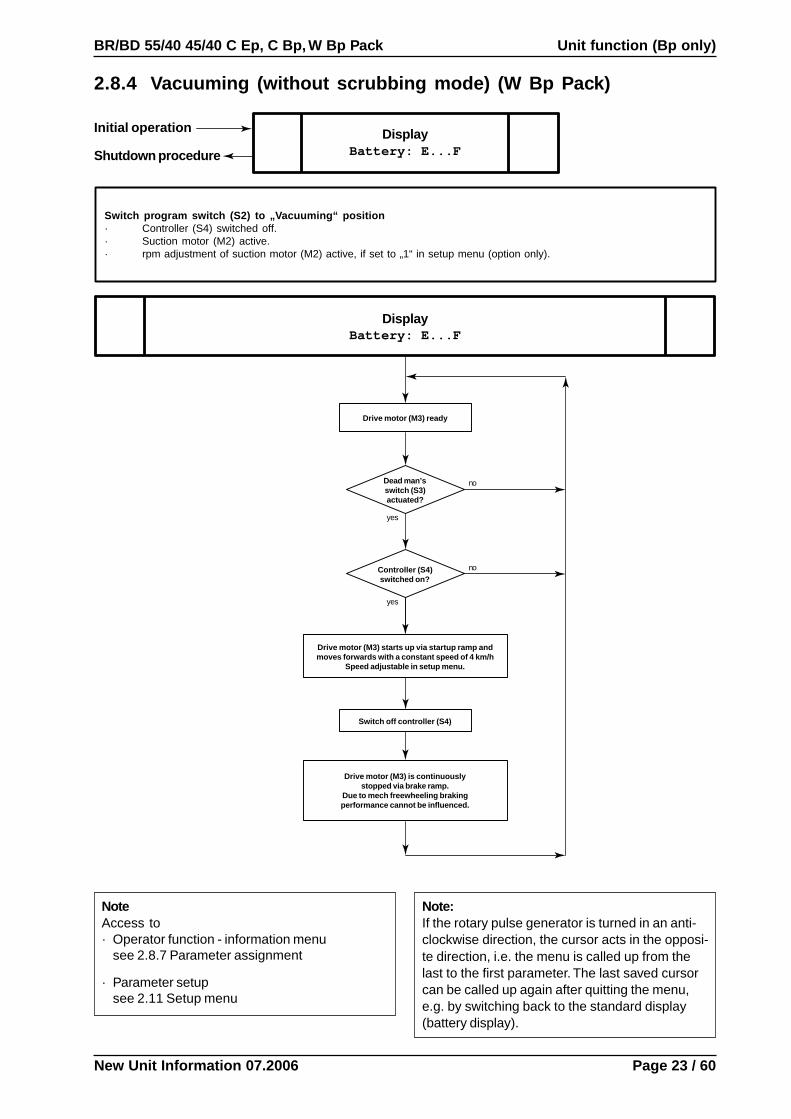
2.8.4 Vacuuming (without scrubbing mode) (W Bp Pack)
DisplayBattery: E...F
Initial operation
Shutdown procedure
Switch program switch (S2) to „Vacuuming“ position· Controller (S4) switched off.· Suction motor (M2) active.· rpm adjustment of suction motor (M2) active, if set to „1“ in setup menu (option only).
DisplayBattery: E...F
Drive motor (M3) ready
Dead man’sswitch (S3)actuated?
Controller (S4)switched on?
no
yes
Drive motor (M3) starts up via startup ramp andmoves forwards with a constant speed of 4 km/h
Speed adjustable in setup menu.
Switch off controller (S4)
Drive motor (M3) is continuouslystopped via brake ramp.
Due to mech freewheeling brakingperformance cannot be influenced.
no
yes
NoteAccess to· Operator function - information menu
see 2.8.7 Parameter assignment
· Parameter setupsee 2.11 Setup menu
Note:If the rotary pulse generator is turned in an anti-clockwise direction, the cursor acts in the opposi-te direction, i.e. the menu is called up from thelast to the first parameter. The last saved cursorcan be called up again after quitting the menu,e.g. by switching back to the standard display(battery display).

New Unit Information 07.2006
Unit function (Bp only) BR/BD 55/40 45/40 C Ep, C Bp, W Bp Pack
Page 24 / 60
2.8.5 Polishing (without vacuuming) (W Bp Pack)
DisplayBattery: E...F
Initial operation
Shutdown procedure
Switch program switch (S2) to „Polishing“ position· Controller (S4) switched off.· FACT active, if set to „1“ in setup menu.
DisplayBattery: E...F
· Red LED lit continuously· After approx 10 sec overload, switching off of
· Brush motor· MV water· Cleaning agent pump (option)
· Display
· Red LED flashes
· Switch off key switch and perform initial operation (2.8.1)
Drive & brush motor(M1 & M3) ready
no
yes
Drive motor (M3) starts up via startup ramp andmoves forwards with a constant speed of 4 km/h
Speed adjustable in setup menu.
Switch off controller (S4)
Drive motor (M3) is continuouslystopped via brake ramp.
Due to mech freewheeling brakingperformance cannot be influenced.
NoteAccess to· Operator function - information menu
see 2.8.7 Parameter assignment
· Parameter setupsee 2.11 Setup menu
Note:If the rotary pulse generator is turned in an anti-clockwise direction, the cursor acts in the opposi-te direction, i.e. the menu is called up from thelast to the first parameter. The last saved cursorcan be called up again after quitting the menu,e.g. by switching back to the standard display(battery display).
Brush overload
Dead man’sswitch (S3)actuated?
Brush motor (M1) active
Brush motoroverload?
yes
no
Controller (S4)switched on?
no
yes

New Unit Information 07.2006
BR/BD 55/40 45/40 C Ep, C Bp, W Bp Pack Unit function (Bp only)
Page 25 / 60
2.8.6 Polishing (with vacuuming) (W Bp Pack)
DisplayBattery: E...F
Initial operation
Shutdown procedure
Switch program switch (S2) to „Polishing with vacuuming“ position· Controller (S4) switched off.· Suction motor (M2) active.· rpm adjustment of suction motor (M2) active, if set to „1“ in setup menu (option only).· FACT active, if set to „1“ in setup menu.
DisplayBattery: E...F
· Red LED lit continuously· After approx 10 sec overload, switching off of
· Brush motor· MV water· Cleaning agent pump (option)
· Display
· Red LED flashes
· Switch off key switch and perform initial operation (2.8.1)
Drive & brush motor(M1 & M3) ready
no
yes
Drive motor (M3) starts up via startup ramp andmoves forwards with a constant speed of 4 km/h
Speed adjustable in setup menu.
Switch off controller (S4)
Drive motor (M3) is continuouslystopped via brake ramp.
Due to mech freewheeling brakingperformance cannot be influenced.
NoteAccess to· Operator function - information menu
see 2.8.7 Parameter assignment
· Parameter setupsee 2.11 Setup menu
Note:If the rotary pulse generator is turned in an anti-clockwise direction, the cursor acts in the opposi-te direction, i.e. the menu is called up from thelast to the first parameter. The last saved cursorcan be called up again after quitting the menu,e.g. by switching back to the standard display(battery display).
Brush overload
Dead man’sswitch (S3)actuated?
Brush motor (M1) active
Brush motoroverload?
yes
no
Controller (S4)switched on?
no
yes

New Unit Information 07.2006
Unit function (Bp only) BR/BD 55/40 45/40 C Ep, C Bp, W Bp Pack
Page 26 / 60
2.8.7 Parameter assignment (W Bp Pack, C Bp / C Bp Pack option)
Shutdown procedure Initial operation
DisplayBattery: E...F
a
a
DisplayCleanspeed: IIIFACT: PowerVACUUM: HIGH
DOSE: 1.0%
Information menu
Manufact. setting
no
yes
no
yes
no
yes
DisplayOpHrs:2h 41min
ProgVers:0.9
BR/D 45-55/40 Bp
Alfred Kärcher
Error instruction
no
yes
10 s
Displayaccept?
DisplayFACT:Powerflashes
10 s
DisplayFACT:FINEflashes
10 s
no
yes
no
yes
DisplayFACT:FINE
new setting saved
DisplayFACT:FINE
new setting saved
Note:If the rotary pulse generator is turned in an anti-clockwise direction, the cursor acts in the opposi-te direction, i.e. the menu is called up from thelast to the first parameter. The last saved cursorcan be called up again after quitting the menu,e.g. by switching back to the standard display(battery display).
CLEANSPEED X X X X X
FACT X X X X only forBR 45-55/40
VACUUM X X X Option
DOSE X X Option (ABS)
INFORMATION MENU XX X X X X
MANUFACTURESETTING X X X X X
- DOSE- FACT- Vacuum- Cleenspeed
are reset
PROGRAMS
PARAMETER
Dri
ve
Wet
scr
ub
wit
hva
cuum
ing
wet
scr
ub
wit
h-
ou
t vac
cum
ing
Vac
uum
ing
Pol
ishi
ng
Po
lish
ing
wit
hva
cuum
ing
Note
Note:Only for display
Final message only appears inevent of error status(Development info)
„Error instruction“
Note:Only for display
„BR/D 45-55/40 Bp“
– BR 45/40 FACT Power/Whisper/Fine– BD 45/40 FACT-menu is suppressed
(90% of the nominal speed)
10 s
Manufacture settinghas been set
no
yes

New Unit Information 07.2006
BR/BD 55/40 45/40 C Ep, C Bp, W Bp Pack Unit function (Bp only)
Page 27 / 60
2.9.1 Initial operation - off mode (C Bp / C Bp Pack)
Switch program switch (S2)to
„Polishing with vacuuming“or
„Wet scrubbing without vacuuming“or
„Vacuuming“or
„Polishing“or
„Polishing with vacuum“
Suction motor free-wheeling
Sh
utd
ow
n p
rece
du
re
Init
ial
op
erat
ion
Suction motor (M2)active and self test
o.k.
Program switch (S2) switch to„OFF“ position
Error LED flashes or
continuously lit
Battery LED (green)
Self test o.k.?
Main relay isengaged
Battery LED (green)
no
yes
yes
no
Activate operator functions:- Wet scrubbing (Chap 2.8.2 – 2.8.3)- Vacuuming (Chap 2.8.4)- Polishing (Chap 2.8.5 - 2.8.6)- Parameter assignment (Chap 2.8.7)- Manufacture setting (Chap 2.10)

New Unit Information 07.2006
Unit function (Bp only) BR/BD 55/40 45/40 C Ep, C Bp, W Bp Pack
Page 28 / 60
2.9.2 Wet scrubbing (with vacuuming) (C Bp / C Bp Pack)
Initial operation
Shutdown procedure
Switch program switch (S2) to „Wet scrubbing with vacuuming“ position· Suction motor (M2) active.· rpm adjustment of suction motor (M2) active, if set to „1“ in setup menu (option only).· RM active, if set to „1“ in setup menu.· FACT active, if set to „1“ in setup menu.
· Red LED lit continuously· After approx 10 sec overload, switching off of
· Brush motor· MV water· Cleaning agent pump (option)
· Red LED flashes
· Switch program switch (S2) to „OFF“and perform initial operation (2.9.1)
Brush motor (M1) ready
no
yes
Cleaning agent pump (option)on
Dead man’sswitch (S3)actuated?
Brush motor (M1) active
Brush motoroverload?
yes
no
(Option)Cleaning agent
switch (S5)on?
no
yes
Battery LED (green)
Battery LED (green)

New Unit Information 07.2006
BR/BD 55/40 45/40 C Ep, C Bp, W Bp Pack Unit function (Bp only)
Page 29 / 60
2.9.3 Wet scrubbing (without vacuuming) (C Bp / C Bp Pack)
Initial operation
Shutdown procedure
Switch program switch (S2) to „Wet scrubbing without vacuuming“ position· RM active, if set to „1“ in setup menu.· FACT active, if set to „1“ in setup menu.
· Red LED lit continuously· After approx 10 sec overload, switching off of
· Brush motor· MV water· Cleaning agent pump (option)
· Red LED flashes
· Switch program switch (S2) to „OFF“and perform initial operation (2.9.1)
Brush motor (M1) ready
no
yes
Cleaning agent pump (option)on
Dead man’sswitch (S3)actuated?
Brush motor (M1) active
Brush motoroverload?
yes
no
(Option)Cleaning agent
switch (S5)on?
no
yes
Battery LED (green)
Battery LED (green)

New Unit Information 07.2006
Unit function (Bp only) BR/BD 55/40 45/40 C Ep, C Bp, W Bp Pack
Page 30 / 60
2.9.4 Vacuuming (without scrubbing mode) (C Bp / C Bp Pack)
Initial operation
Shutdown procedure
Switch program switch (S2) to „Vacuuming“ position· Suction motor (M2) active.· rpm adjustment of suction motor (M2) active, if set to „1“ in setup menu (option only).
Battery LED (green)
Battery LED (green)

New Unit Information 07.2006
BR/BD 55/40 45/40 C Ep, C Bp, W Bp Pack Unit function (Bp only)
Page 31 / 60
2.9.5 Polishing (without vacuuming) (C Bp / C Bp Pack)
Initial operation
Shutdown procedure
Switch program switch (S2) to „Polishing“ position· FACT active, if set to „1“ in setup menu.
· Red LED lit continuously· After approx 10 sec overload, switching off of
· Brush motor· MV water· Cleaning agent pump (option)
· Red LED flashes
· Switch program switch (S2) to „OFF“and perform initial operation (2.9.1)
Brush motor (M1) ready
no
yes
Dead man’sswitch (S3)actuated?
Brush motor (M1) active
Brush motoroverload?
yes no
Battery LED (green)
Battery LED (green)

New Unit Information 07.2006
Unit function (Bp only) BR/BD 55/40 45/40 C Ep, C Bp, W Bp Pack
Page 32 / 60
2.9.6 Polishing (with vacuuming) (C Bp / C Bp Pack)
Initial operation
Shutdown procedure
Switch program switch (S2) to „Polishing with vacuuming“ position· Suction motor (M2) active.· rpm adjustment of suction motor (M2) active, if set to „1“ in setup menu (option only).· FACT active, if set to „1“ in setup menu.
· Red LED lit continuously· After approx 10 sec overload, switching off of
· Brush motor· MV water· Cleaning agent pump (option)
· Red LED flashes
· Switch program switch (S2) to „OFF“and perform initial operation (2.9.1)
Brush motor (M1) ready
no
yes
Dead man’sswitch (S3)actuated?
Brush motor (M1) active
Brush motoroverload?
yes no
Battery LED (green)
Battery LED (green)
New Unit Information 07.2006
BR/BD 55/40 45/40 C Ep, C Bp, W Bp Pack Unit function (Bp only)
Page 33 / 60
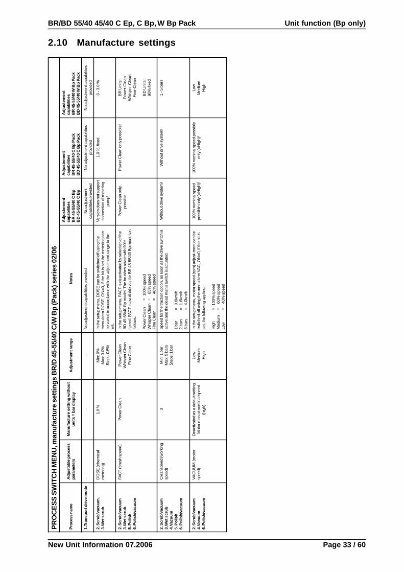
2.10 Manufacture settingsP
RO
CE
SS
SW
ITC
H M
EN
U, m
anu
fact
ure
set
tin
gs
BR
/D 4
5-55
/40
C/W
Bp
(Pac
k) s
erie
s 02
/06
Pro
cess
nam
eA
djus
tabl
e pr
oces
spa
ram
eter
sM
anu
fact
ure
set
tin
g w
ith
ou
tu
nit
s =
bar
dis
pla
yA
dju
stm
ent r
ang
eN
ote
s
Ad
just
emen
tca
pabi
litie
sB
R 4
5-55
/40
C B
pB
D 4
5-55
/40
C B
p
Ad
just
emen
tca
pabi
litie
sB
R 4
5-55
/40
C B
p P
ack
BD
45-
55/4
0 C
Bp
Pac
k
Ad
just
emen
tca
pabi
litie
sB
R 4
5-55
/40
W B
p P
ack
BD
45-
55/4
0 W
Bp
Pac
k
1. T
ran
spo
rt d
rive
mo
de
––
–N
o ad
just
men
t cap
abili
ties
prov
ided
No
adju
stm
ent
capa
bilit
ies
prov
ided
No
adju
stm
ent c
apab
ilitie
spr
ovid
edN
o ad
just
men
t cap
abili
ties
prov
ided
2. S
crub
/vac
uum
,3.
Wet
scr
ub
DO
SE
(che
mic
alm
eter
ing)
1.0
%M
in: 0
%M
ax: 3
.0%
Ste
ps: 0
.5%
In th
e se
tup
men
u, D
OS
E c
an b
e sw
itche
d of
f usi
ng th
em
enu
item
DO
SE
_ON
=0, i
f the
bit
is s
et th
e m
eter
ing
can
be v
arie
d in
acc
orda
nce
with
the
adju
stm
ent r
ange
to th
ele
ft.
Vers
ion
does
not
sup
port
conn
ectio
n of
met
erin
gpu
mp!
1.0
%, f
ixed
0 - 3
.0 %
2. S
crub
/vac
uum
3. W
et s
cru
b5.
Pol
ish
6. P
olis
h/va
cuum
FAC
T (b
rush
spe
ed)
Pow
er C
lean
Pow
er C
lean
Whi
sper
Cle
anF
ine
Cle
an
In th
e se
tup
men
u, F
AC
T is
dea
ctiv
ated
by
sele
ctio
n of
the
BD
45-
55/4
0 B
p m
odel
. The
bru
shes
rota
te w
ith 9
0%sp
eed.
FA
CT
is a
vaila
ble
via
the
BR
45-
55/4
0 B
p m
odel
as
follo
ws:
Pow
er C
lean
= 1
00%
spe
edW
hisp
er C
lean
=
65%
spe
edF
ine
Cle
an=
4
0% s
peed
Pow
er C
lean
onl
ypo
ssib
le!
Pow
er C
lean
onl
y po
ssib
le!
BR
Uni
ts:
Pow
er-C
lean
Whi
sper
-Cle
anF
ine-
Cle
an
BD
Uni
ts:
90%
fixe
d
2. S
crub
/vac
uum
3. W
et s
cru
b4.
Vac
uu
m5.
Pol
ish
6. P
olis
h/va
cuum
Cle
ansp
eed
(wor
king
spee
d)3
Min
: 1 b
arM
ax: 5
bar
sS
teps
: 1 b
ar
Spe
ed fo
r the
trac
tion
optio
n, a
s so
on a
s th
e dr
ive
switc
h is
activ
e an
d th
e de
ad m
an's
sw
itch
is a
ctua
ted.
1 ba
r=
0.
8km
/h2
bars
=
1.6k
m/h
5 ba
rs=
4.
0km
/h
With
out d
rive
syst
em!
With
out d
rive
syst
em!
1 - 5
bar
s
2. S
crub
/vac
uum
4. V
acu
um
6. P
olis
h/va
cuum
VAC
UU
M (
mot
orsp
eed)
Dea
ctiv
ated
as
a de
faul
t set
ting.
Mot
or ru
ns a
t nom
inal
spe
ed(h
igh)
.
Low
Med
ium
Hig
h
In th
e se
tup
men
u, m
otor
spe
ed (r
pm) a
djus
t-m
ent c
an b
esw
itche
d of
f usi
ng th
e m
enu
item
VA
C_O
N=0
, if t
he b
it is
set,
the
follo
win
g ap
plie
s:
Hig
h=
100
% s
peed
Med
ium
=
60%
spe
edLo
w=
4
0% s
peed
100%
nom
inal
spe
edpo
ssib
le o
nly
(=H
igh)
!10
0% n
omin
al s
peed
pos
sibl
eon
ly (=
Hig
h)!
Low
Med
ium
Hig
h

New Unit Information 07.2006
Unit function (Bp only) BR/BD 55/40 45/40 C Ep, C Bp, W Bp Pack
Page 34 / 60
2.11.1 Access to the setup menu (W Bp Pack)
DisplayBattery: E...F
Switch program switch (S2) to„Wet scrubbing without
vacuuming“ position
10 s
no
yes
no
yes
no
yes
no
yes
DisplayParameter setup
I-Button - press 3 times in 2 sec
I-Button - continue to turn until
Parameter setup
appears
Explanations on Displaysee 2.11.3
Noteon displayBR 45-55/40 BpFACT (Power-Whisper-Fine) is accessible hereorBD 45-55/40 BpFACT (Power-Whisper-Fine) is suppressed here,the brush speed is then fixed at 90% of the nominalspeed.
DisplayLanguageE=0,D=1:1
EndPtVolt:12.0V
Standby :30 min
BrushCurrent:60A
MotorCurrent:30A
DriveCurrent:15A
SuctionFree-Wheel:10s
BR 45-55/40 Bpor
BD 45-55/40 Bp
VAC_ON 1=Y,0=N:0
DOSEON 1=Y,0=N:0
Trans.speed IIII
DriveMotorRamp:3
BrushRamp :9
LCD Contrast :22
2.11.2 Changes & saving in the setup menu
Note:If the rotary pulse generator is turned in an anti-clockwise direction, the cursor acts in the opposite direction, i.e. the menu iscalled up from the last to the first parameter. The last saved cursor can be called up again after quitting the menu, e.g. byswitching back to the standard display (battery display).

New Unit Information 07.2006
BR/BD 55/40 45/40 C Ep, C Bp, W Bp Pack Unit function (Bp only)
Page 35 / 60
2.11.2 Saving in the setup menu (W Bp Pack)
Note:If the rotary pulse generator is turned in an anti-clockwise direction, the cursor acts in the opposite direction, i.e. the menu iscalled up from the last to the first parameter. The last saved cursor can be called up again after quitting the menu, e.g. byswitching back to the standard display (battery display).
2.11.1 Access to the setup menu
DisplayLanguageE=0,D=1:1
DisplayBattery: E...F
The last set adjustmentparameter is displayed
no
yes
no
yes
no
yes
Parameter value rigidadjustment value flashes
New parameter value isdisplayed flashing
New parameter value isdisplayed and savedFlash function ends
Nextadjustment parameter is
displayed
10 s
10 s
10 s
10 s
Changes are saved
Old value is returned
New Unit Information 07.2006
Unit function (Bp only) BR/BD 55/40 45/40 C Ep, C Bp, W Bp Pack
Page 36 / 60
2.11.3 Setup menu display (W Bp Pack only)
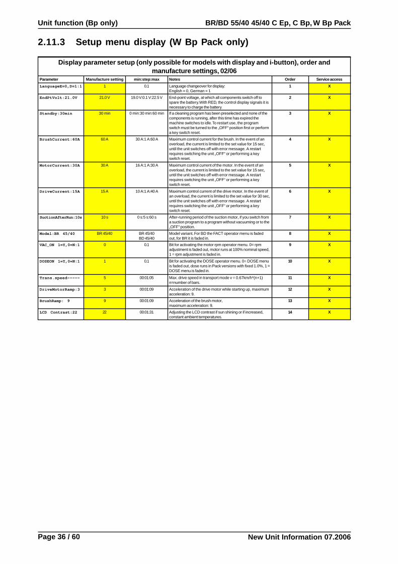
Display parameter setup (only possible for models with display and i-button), order andmanufacture settings, 02/06
Parameter Manufacture setting min:step:max Notes Order Service access
LanguageE=0,D=1:1 1 0.1 Language changeover for display:English = 0, German = 1
1 X
EndPtVolt:21.0V 21.0 V 19.0 V:0.1 V:22.5 V End-point voltage, at which all components switch off tospare the battery. With RED, the control display signals it isnecessary to charge the battery.
2 X
Standby:30min 30 min 0 min:30 min:60 min If a cleaning program has been preselected and none of thecomponents is running, after this time has expired themachine switches to idle. To restart use, the programswitch must be turned to the „OFF“ position first or performa key switch reset.
3 X
BrushCurrent:60A 60 A 30 A:1 A:60 A Maximum control current for the brush. In the event of anoverload, the current is limited to the set value for 15 sec,until the unit switches off with error message. A restartrequires switching the unit „OFF“ or performing a keyswitch reset.
4 X
MotorCurrent:30A 30 A 16 A:1 A:30 A Maximum control current of the motor. In the event of anoverload, the current is limited to the set value for 15 sec,until the unit switches off with error message. A restartrequires switching the unit „OFF“ or performing a keyswitch reset.
5 X
DriveCurrent:15A 15 A 10 A:1 A:40 A Maximum control current of the drive motor. In the event ofan overload, the current is limited to the set value for 30 sec,until the unit switches off with error message. A restartrequires switching the unit „OFF“ or performing a keyswitch reset.
6 X
SuctionAfterRun:10s 10 s 0 s:5 s:60 s After-running period of the suction motor, if you switch froma suction program to a program without vacuuming or to the„OFF“ position.
7 X
Model:BR 45/40 BR 45/40 BR 45/40BD 45/40
Model variant. For BD the FACT operator menu is fadedout, for BR it is faded in.
8 X
VAC_ON 1=Y,0=N:1 0 0.1 Bit for activating the motor rpm operator menu. 0= rpmadjustment is faded out, motor runs at 100% nominal speed,1 = rpm adjustment is faded in.
9 X
DOSEON 1=Y,0=N:1 1 0.1 Bit for activating the DOSE operator menu. 0= DOSE menuis faded out, dose runs in Pack versions with fixed 1.0%, 1 =DOSE menu is faded in.
10 X
Trans.speed----- 5 00:01:05 Max. drive speed in transport mode v = 0.67km/h*(n+1)n=number of bars.
11 X
DriveMotorRamp:3 3 00:01:09 Acceleration of the drive motor while starting up, maximumacceleration: 9.
12 X
BrushRamp: 9 9 00:01:09 Acceleration of the brush motor,maximum acceleration: 9.
13 X
LCD Contrast:22 22 00:01:31 Adjusting the LCD contrast if sun shining or if increased,constant ambient temperatures.
14 X

New Unit Information 07.2006
BR/BD 55/40 45/40 C Ep, C Bp, W Bp Pack Unit function (Ep only)
Page 37 / 60
1 Chassis2 Cover, brush motor (M1)3 Protection profile4 Connection cable5 Freshwater inlet hose
3.1 Chassis (Ep only)
1
5
4
2
3
New Unit Information 07.2006
Unit function (Ep only) BR/BD 55/40 45/40 C Ep, C Bp, W Bp Pack
Page 38 / 60
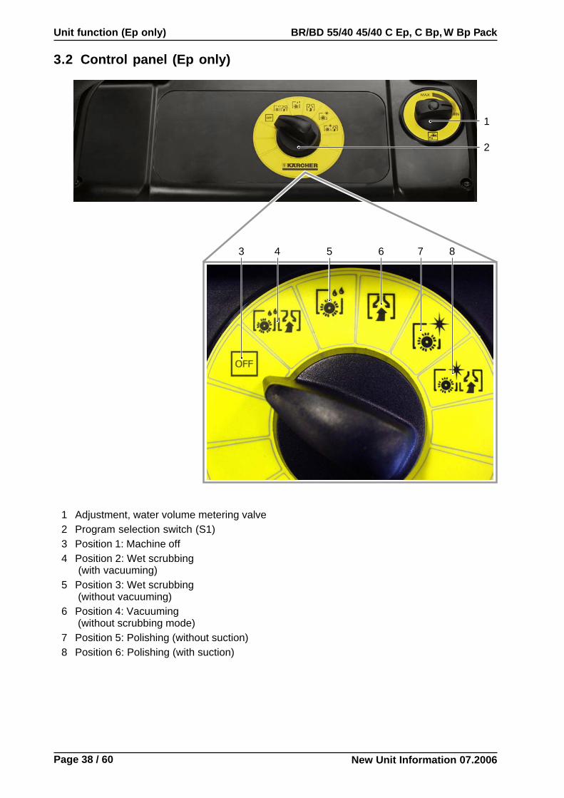
3.2 Control panel (Ep only)
3 4 5 6 7 8
1
2
1 Adjustment, water volume metering valve2 Program selection switch (S1)3 Position 1: Machine off4 Position 2: Wet scrubbing
(with vacuuming)5 Position 3: Wet scrubbing
(without vacuuming)6 Position 4: Vacuuming
(without scrubbing mode)7 Position 5: Polishing (without suction)8 Position 6: Polishing (with suction)

New Unit Information 07.2006
BR/BD 55/40 45/40 C Ep, C Bp, W Bp Pack Unit function (Ep only)
Page 39 / 60
3.2 Control panel, view from below (Ep only)
1 Operating capacitor (C1)2 Mains cable3 Adjustment, water volume control4 Plug and socket connections5 Interference suppression capacitor (C2)6 Program selection switch (S1)
1
6
2
4
3
6
5

New Unit Information 07.2006
Unit function (Ep only) BR/BD 55/40 45/40 C Ep, C Bp, W Bp Pack
Page 40 / 60
3.3 Unit switch with motor protection switch (Q1) (Ep only)
1 Retaining screws, handle2 Retaining screws, housing cover3 Housing cover4 Unit switch with motor protection switch
(Q1)
1
2
2
Housing open– Screw out the retaining screws (2).– Undo the retaining screws (1).– Remove housing cover (3)
3
2
4
New Unit Information 07.2006
BR/BD 55/40 45/40 C Ep, C Bp, W Bp Pack Unit function (all versions)
Page 41 / 60
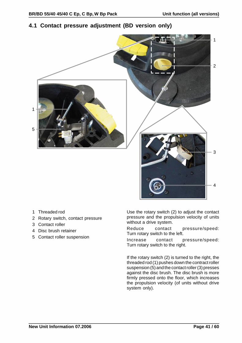
4.1 Contact pressure adjustment (BD version only)
2
1
1
5
1 Threaded rod2 Rotary switch, contact pressure3 Contact roller4 Disc brush retainer5 Contact roller suspension
Use the rotary switch (2) to adjust the contactpressure and the propulsion velocity of unitswithout a drive system.Reduce contact pressure/speed:Turn rotary switch to the left.Increase contact pressure/speed:Turn rotary switch to the right.
If the rotary switch (2) is turned to the right, thethreaded rod (1) pushes down the contract rollersuspension (5) and the contact roller (3) pressesagainst the disc brush. The disc brush is morefirmly pressed onto the floor, which increasesthe propulsion velocity (of units without drivesystem only).
3
4

New Unit Information 07.2006
Unit function (all versions) BR/BD 55/40 45/40 C Ep, C Bp, W Bp Pack
Page 42 / 60
4.2 Transport roller
1
2
3
4
1 Deflection pulley, cable control2 Cable control3 Transport roller4 Suspension, transport roller
When the foot pedal is pressed, the transportroller is swivelled out by a control cable anddeflection pulley.The unit can now be freely pushed.

New Unit Information 07.2006
BR/BD 55/40 45/40 C Ep, C Bp, W Bp Pack Unit function (all versions)
Page 43 / 60
4.3 Brush head (BR version)
2
3
6
5
4
1 Protection profile2 Unlock button, brush roller bracket3 Brush roller bracket4 Safety bolt, brush roller bracket5 Brush rollers6 Debris container
Debris container
6
Replace the brush rollerThe brush rollers (5) are removed from the brushhead for cleaning or replacement as follows:– Empty dirty water tank.– Press down unit at push handle.– Swivel out transport roller using foot pedal
control.– Open brush roller bracket (3) with unlock
button (2) and swivel out of the way.– Remove brush rollers (5) from the brush head.– Insert new brush rollers and reclose bracket
(3).– Swivel in transport roller using foot pedal
control.
1
NoteIf the unit is tilted too far in the direction of thepush handle, residual water can escapefrom the freshwater metering valve.

New Unit Information 07.2006
Unit function (all versions) BR/BD 55/40 45/40 C Ep, C Bp, W Bp Pack
Page 44 / 60
4.3 Brush head (BD version)
5
1
1 Bracket, disc brush change2 Retainer, disc brush3 Guide roller4 Contact pressure adjustment5 Pedal, disc brush change
2
Replacing the disc brushThe disc bush is pushed off the retainer (2) bythe bracket (1) by pressing the pedal (5).– Empty dirty water tank.– Press down unit at push handle.– Swivel out transport roller using foot pedal
control.– Use the pedal (5) to release the disc brush
from the retainer (2). The disc brush can beremoved.
– Place new disc brush under brush head.– Swivel in transport roller using foot pedal
control.– Lower the unit onto the disc brush until it latches
into position.
3
4
NoteIf the unit is tilted too far in the direction of thepush handle, residual water can escapefrom the freshwater metering valve.

New Unit Information 07.2006
BR/BD 55/40 45/40 C Ep, C Bp, W Bp Pack Unit function (all versions)
Page 45 / 60
4.4 Brush drive assembly (BR version)
1 Housing, reduction gear transmission2 Cover, toothed belt3 Cable control, transport roller4 Transport roller5 Screws, toothed belt cover6 Brush motor (M1)7 Fan wheel, brush motor8 Connection cable9 Freshwater inlet hose
10 Driving gear, brush motor11 Toothed belt
Belt tensionThe toothed belt (11) must be so taut that it canonly be pushed in by approx 3 mm (see arrow).
15
6
1
987
2
4
5
3
10
11
12
13
14
12 Tension roller, toothed belt13 Locking screw, tension roller14 Driving gear, brush rollers15 Brush roller carrier

New Unit Information 07.2006
Unit function (all versions) BR/BD 55/40 45/40 C Ep, C Bp, W Bp Pack
Page 46 / 60
4.4 Brush drive assembly (BD version)
1 Driving gear, brush motor2 Toothed belt3 Brush motor (M1)4 Pinion, disc brush
Belt tensionThe toothed belt (2) cannot be tightened. Thebelt tension results from the assembly of thetoothed belt (2).– Insert the toothed belt (2) in the driving gear
(1).– Push the toothed belt (2) onto the pinion (4).
3
1
2
4

New Unit Information 07.2006
BR/BD 55/40 45/40 C Ep, C Bp, W Bp Pack Unit function (all versions)
Page 47 / 60
4.5 Solenoid valve, water stop (Y1)
1 Freshwater inlet hose2 Cable - plug and socket connection, soleno-
id valve water stop (Y1)3 Solenoid valve, water stop (Y1)
21
32
3
1
BR version BD version
New Unit Information 07.2006
Unit function (all versions) BR/BD 55/40 45/40 C Ep, C Bp, W Bp Pack
Page 48 / 60
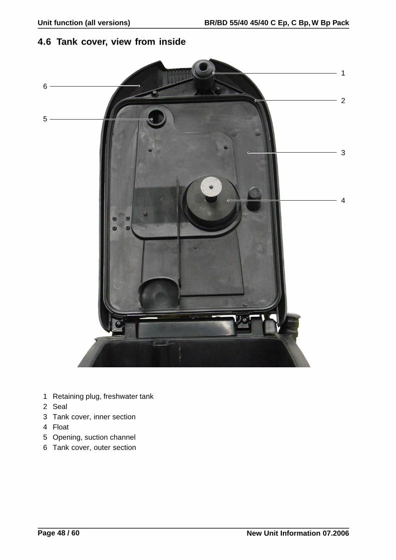
1 Retaining plug, freshwater tank2 Seal3 Tank cover, inner section4 Float5 Opening, suction channel6 Tank cover, outer section
2
1
4.6 Tank cover, view from inside
3
4
5
6

New Unit Information 07.2006
BR/BD 55/40 45/40 C Ep, C Bp, W Bp Pack Unit function (all versions)
Page 49 / 60
1 Dirty water tank2 Outlet, dirty water3 Baffle plate4 Tank inlet, freshwater tank5 Fluff strainer, vacuum channel6 Dirty water suction tube
6
4.7 Dirty water tank
1
3
2
4
5

New Unit Information 07.2006
Unit function (all versions) BR/BD 55/40 45/40 C Ep, C Bp, W Bp Pack
Page 50 / 60
4
1
2
4.8 Suction motor (M2)
1 Suction hose2 Retaining clip, suction hose3 Connection cable4 Suction motor (M2)
3
New Unit Information 07.2006
BR/BD 55/40 45/40 C Ep, C Bp, W Bp Pack Unit function (all versions)
Page 51 / 60
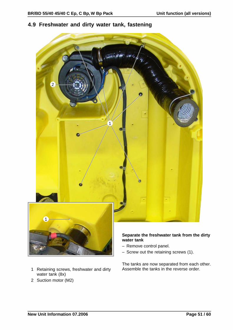
4.9 Freshwater and dirty water tank, fastening
2
1 Retaining screws, freshwater and dirtywater tank (8x)
2 Suction motor (M2)
Separate the freshwater tank from the dirtywater tank– Remove control panel.– Screw out the retaining screws (1).
The tanks are now separated from each other.Assemble the tanks in the reverse order.
1
1

New Unit Information 07.2006
Unit function (all versions) BR/BD 55/40 45/40 C Ep, C Bp, W Bp Pack
Page 52 / 60
4.9 Freshwater and dirty water tank (separated)
1 Dirty water tank2 Fresh water tank
1
2

New Unit Information 07.2006
BR/BD 55/40 45/40 C Ep, C Bp, W Bp Pack Unit function (all versions)
Page 53 / 60
4.9 Freshwater and dirty water tank, tank seals
1 Seals (3x)2 Freshwater tank, inside3 Seals, retaining screws (8x)
NoteBefore assembling the tanks, the seals (1)must be greased with silicon grease.
1
1
2
3

New Unit Information 07.2006
Circuit diagram BR/BD 55/40 45/40 C Ep, C Bp, W Bp Pack
Page 54 / 60
5.1 BR/BD 55/40, 45/40 C Ep (Circuit diagram 0.088-845)C
1O
perating capacitor (30 µF)
C2
Interference suppression capacitor (0.22 µF)
M1
Brush m
otorM
2S
uction motor
Q1
Unit sw
itch with m
otor protection switch
S1
Program
selection switch
Y1
Solenoid valve w
ater stopX
1M
ains plug

New Unit Information 07.2006
BR/BD 55/40 45/40 C Ep, C Bp, W Bp Pack Circuit diagram
Page 55 / 60
5.2 BR/BD 55/40, 45/40 C Bp (Circuit diagram 0.088-843)
A0
Main control printed circuit board,
info button and display module
(option)A
1M
ain control printed circuit boardF
1M
ain fuse (100 A)
G1
Battery 24 V
/ 100 Ah
H1
Indicator lamp, battery m
onitoring andfault
M1
Brush m
otorM
2S
uction motor
M4
Cleaning agent pum
p (option)S
2P
rogram selection sw
itchS
3M
icroswitch, brush m
otorS
5S
witch, cleaning agent (option)
Y1
Solenoid valve, w
ater stop

New Unit Information 07.2006
Circuit diagram BR/BD 55/40 45/40 C Ep, C Bp, W Bp Pack
Page 56 / 60
5.3 BR/BD 55/40, 45/40 C Bp Pack / W Bp Pack(Circuit diagram 0.088-844)
A0
Main control printed circuit board,
info button and display module
(option)A
1M
ain control printed circuit boardF
1M
ain fuse (100 A)
G1
Battery 24 V
/ 100 Ah
H1
Indicator lamp, battery m
onitoring
and faultM
1B
rush motor
M2
Suction m
otorM
3D
rive motor (O
ption)M
4C
leaning agent pump (option)
S0
Key sw
itch (option)
S1
EM
ER
GE
NC
Y-S
TO
P button
(option)S
2P
rogram selection sw
itchS
3M
icroswitch, brush m
otorS
4S
witch, drive m
otor (option)S
5S
witch, cleaning agent (option)
U1
Battery charger 24 V
/ 15 AY
1S
olenoid valve, water stop

New Unit Information 07.2006
BR/BD 55/40 45/40 C Ep, C Bp, W Bp Pack Replacement times
Page 57 / 60
6.1 BR version replacement times:
Wearing part
Brush roller
Skid
Sealing ring FW-SW
Guide roller, suction bar
Roller D60
Rubber lip seal set
Toothed belt, brush
Sealing profile
Drain hose
Suction hose
Carbon brush, suction motor
Ball bearing, brush drive assembly
Guide roller, brush head
Wheel D200
Solenoid valve, water stop
Suction motor
Brush motor
Part number
4.762-392
5.056-010
5.363-647
5.515-267
5.515-280
6.273-213
6.348-429
6.366-043
6.391-070
6.391-474
6.610-220
6.401-363
6.435-341
6.435-356
6.472-997
6.490-115
6.613-108
Replacement time in minutes
5
15
10
10
10
10
10
10
5
5
10
20
5
10
20
15
20
6.2 BD version replacement times
Wearing part
Disc brush
Sealing ring FW-SW
Guide roller, suction bar
Roller D60
Rubber lip seal set
Toothed belt
Sealing profile
Drain hose
Suction hose
Carbon brush, suction motor
Ball bearing, pad drive unit
Deflection roller, brush head
Wheel D200
Solenoid valve, water stop
Suction motor
Brush motor
Part number
4.905-003
5.363-647
5.515-267
5.515-280
6.273-213
6.348-384
6.366-043
6.391-070
6.391-474
6.610-220
7.401-173
5.515-096
6.435-356
6.472-997
6.490-115
6.612-750
Replacement time in minutes
5
10
10
10
10
10
10
5
5
10
40
10
10
20
15
30

New Unit Information 07.2006
Troubleshooting BR/BD 55/40 45/40 C Ep, C Bp, W Bp Pack
Page 58 / 60
7.1 Troubleshooting without displays
Fault
Unit won’t start
Solution
– Check whether the mains plug is plugged in (Ep only).– Unit is in standby mode/program selection switch is set to
Position „1“ (Drive/OFF) and then switch to required program(Bp only).
– Connect/check/charge batteries (Bp only).– Check battery charge control (Bp only).– Check/replace fuse (F1) (Bp only).– Check/replace program selection switch (S1/S2).– Check/replace unit switch with motor protection switch (Q1)
(Ep only)– Check/replace main control printed circuit board (A1).– Check whether charger (U1) is plugged in/unplug
(Bp only).– Check/replace charger (U1) (Bp only).
No or too little watersupply
– Check freshwater level/top up.– Check/clean water inlet.– Check/clean/replace solenoid valve, water stop (Y1).
Insufficient suction perfor-mance
– Check seal between dirty water tank and tank cover for leaks/clean/replace.
– Check/replace float.– Check/clean fluff strainer.– Check/clean/replace rubber strips on suction bar.– Check suction hose for blockage/remove blockage.– Check whether cover is closed at dirty water drain hose.– Check suction bar adjustment.– Check/replace suction motor (M2).
Inadequate cleaningresult
– Check brushes for wear and dirt/clean/replace.– Check freshwater level/top up.– Check/clean water inlet.– Check/clean/replace solenoid valve, water stop (Y1).
Brushes won’t turn – Check electrical connection, brush motor (M3).– Check whether foreign body is blocking the brush rollers or
disc brush/remove foreign body/replace brush rollers or discbrush.
– Check/replace toothed belt.– Check/replace unit switch with motor protection switch (Q1)
(Ep only)– Check/replace main control printed circuit board (A1).
Cleaning agent is not added – Check level in cleaning agent tank.– Check/replace cleaning agent switch (S5).– Check/replace cleaning agent pump (M4).
Unit won’t drive(W Bp Pack only)
– Check whether charger (U1) is plugged in/unplug(Bp only).
– Check/replace fuse (F1).– Check/replace program selection switch (S2).– Check/replace main control printed circuit board (A1).– Check/replace drive motor (M1).

New Unit Information 07.2006
BR/BD 55/40 45/40 C Ep, C Bp, W Bp Pack Troubleshooting
Page 59 / 60
Note:If an error occurs, always place the program selection switch (S2) in the „Drive“ position first, place key switch in position „0“. Wait for approx 15 seconds, before switching back on.If the error continues to occur, phone customer service!
7.2 Troubleshooting with displays (W Bp Pack only)
DisplayErrorCode
Error Source ActionLED displayoverload
Drivingoperationpossible
Suctionoperationpossible
Scrubbingoperationpossible
Polishingoperationpossible
Brushmot.fault=1 1 Brush motor short circuit 1*flash XX
Vac.mot.fault=1 2 Suction motor short circuitCall customer service!
1*flash XX
Check battery! 3Battery voltage not between 17and 33 V.
4*flash
Hot, let cool! 4 Control temperature too highLeaven controls to cool downfor at least 15 minutes.
3*flash X X XX
Pcb. fault=4 5 Printed circuit board defectiveConti-nuously lit
Pcb. fault=4 6 Printed circuit board defectiveConti-nuously lit
Pcb. fault=4 7 Printed circuit board defectiveConti-nuously lit
Brushmot.fault=2 8 Brush motor cable break 2*flash XX
Vac.mot.fault=2 9 Suction motor cable break 2*flash XX
Pcb. fault=4 10 Printed circuit board defectiveConti-nuously lit
X X
Pcb. fault=4 11 Printed circuit board defectiveConti-nuously lit
Pcb. fault=4 12 Printed circuit board defectiveConti-nuously lit
Pcb. fault=4 13 Printed circuit board defective
Call customer service!
Conti-nuously lit
Pcb. fault=4 14 Printed circuit board defectiveConti-nuously lit
Pcb. fault=4 15Printed circuit board defectiveor load directly connectedbetween +Ubat and earth
Conti-nuously lit
Pcb. fault=4 16 Printed circuit board defectiveConti-nuously lit
Pcb. fault=4 17 Printed circuit board defectiveConti-nuously lit
Valve fault=2 18 Solenoid valve wire break 2*flash X XX
Vac.mot.fault=3 20 Suction motor overload
Set program selection switchin "Transport" position. Thenreselect cleaning program. Ifthe error continues to occur,call customer service!
3*flash XX
Brush Overload! 21 Brush motor overload
Set program selection switchin "Transport" position. Thenreselect cleaning program. Ifthe error continues to occur,call customer service!
3*flash XX
Valve fault=1 22 Solenoid valve short circuit Call customer service! 1*flash X XX
Check Battery! 23Battery voltage too highduring charging
Unplug battery charger at thesocket. You can now cleanagain. Nevertheless, informcustomer service!
4*flash
Drivemot.fault=1 24 Drive motor short circuit Call customer service! 1*flash X X X
Drivemot.fault=2 25 Drive motor wire break Call customer service! 2*flash X X X
Pcb. fault=4 26 Printed circuit board defective Call customer service!Conti-nuously lit
X X X
Wat.Pump fault=1 30 Water pump overload
Set program selection switchin "Transport" position. Thenreselect cleaning program. Ifthe error continues to occur,call customer service!
1*flash X X XX
Drivemot.fault=3 31 Drive motor overload
Set program selection switchin "Transport" position. Thenreselect cleaning program. DoNOT run the machine onSLOPES > 2%. If the errorcontinues to occur, phonecustomer service!
3*flash X X X
Battery fault! 32 Battery fault
Unplug battery charger at thesocket. You can now cleanagain. Nevertheless, informcustomer service!
4*flash
Emergency button 33 Emergency stop buttonpressed(display possible duringcharging operation only!)
Release EMERGENCY STOPbutton. Switch off key switch.Unplug battery charger fromthe mains socket. Wait for 15seconds. Then restartcharging by plugging thecharger into the mainssocket.
4*flash
Pcb. fault=4 34 General relay sticks Call customer service!Conti-nuously lit

New Unit Information 07.2006
Technical specifications BR/BD 55/40 45/40 C Ep, C Bp, W Bp Pack
Page 60 / 60
The technical data sheet and the circuit diagram will be included in the next issue of the spare partsCD-ROM (DISIS) and are also available in kaercher-inside (https://kaercher-inside.com).
If required, the operating instructions and the spare parts lists can be ordered as a paper copy fromthe spare parts service by quoting the relevant part number.
9 Special tool
No special tools are required.
10 Tightening torque
No details.
8 Technical specifications
Unit type
BR 45/40 C Ep
BD 45/40 C Ep
BR 45/40 C Bp
BD 45/40 C Bp
BR 45/40 C Bp Pack
BD 45/40 C Bp Pack
BR 45/40 W Bp Pack
BD 45/40 W Bp Pack
BR 55/40 C Ep
BD 55/40 C Ep
BR 55/40 C Bp
BD 55/40 C Bp
BR 55/40 C Bp Pack
BD 55/40 C Bp Pack
BR 55/40 W Bp Pack
BD 55/40 W Bp Pack
Unit No.
1.533-100.0
1.533-101.0
1.533-104.0
1.533-105.0
1.533-106.0
1.533-107.0
1.533-108.0
1.533-109.0
1.533-150.0
1.533-151.0
1.533-154.0
1.533-155.0
1.533-156.0
1.533-157.0
1.533-158.0
1.533-159.0
Circuitdiagram
0.088-845.0
0.088-845.0
0.088-843.0
0.088-843.0
0.088-844.0
0.088-844.0
0.088-844.0
0.088-844.0
0.088-845.0
0.088-845.0
0.088-843.0
0.088-843.0
0.088-844.0
0.088-844.0
0.088-844.0
0.088-844.0
Operatinginstructions
5.961-741.0
5.961-741.0
5.961-706.0
5.961-706.0
5.961-706.0
5.961-706.0
5.961-706.0
5.961-706.0
5.961-741.0
5.961-741.0
5.961-706.0
5.961-706.0
5.961-706.0
5.961-706.0
5.961-706.0
5.961-706.0
Spare partslist
5.970-517.0
5.970-517.0
5.970-517.0
5.970-517.0
5.970-517.0
5.970-517.0
5.970-517.0
5.970-517.0
5.970-517.0
5.970-517.0
5.970-517.0
5.970-517.0
5.970-517.0
5.970-517.0
5.970-517.0
5.970-517.0