Embed Size (px)
Citation preview
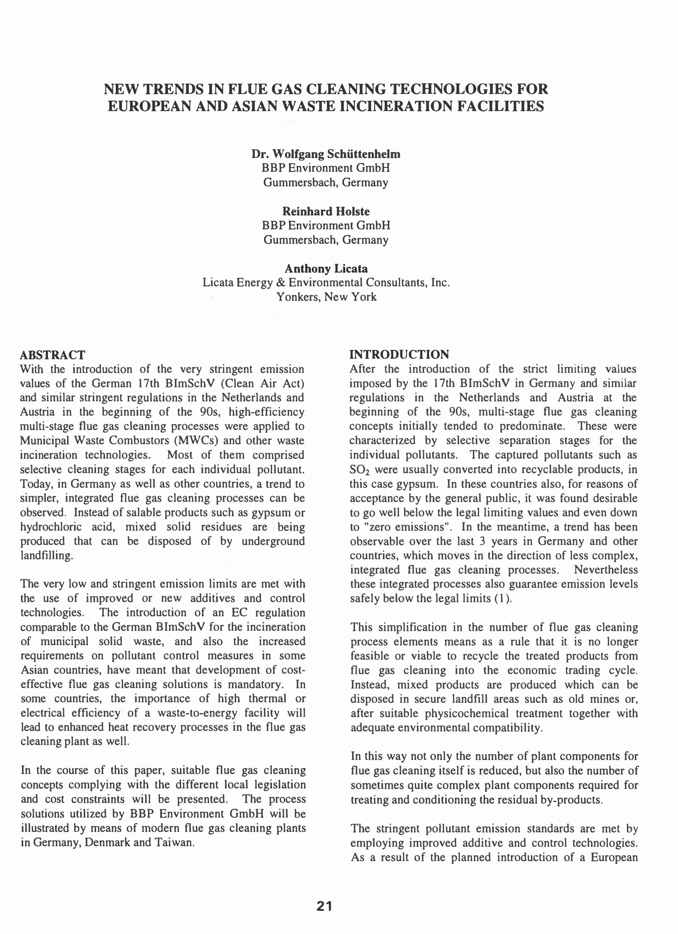
NEW TRENDS IN FLUE GAS CLEANING TECHNOLOGIES FOR EUROPEAN AND ASIAN WASTE INCINERATION FACILITIES
Dr. Wolfgang Schiittenhelm BBP Environment GmbH Gummersbach, Germany
Reinhard Holste BBP Environment GmbH Gummersbach, Germany
Anthony Licata Licata Energy & Environmental Consultants, Inc.
Yonkers, New York
ABSTRACT With the introduction of the very stringent emission values of the German 17th BImSchV (Clean Air Act) and similar stringent regulations in the Netherlands and Austria in the beginning of the 90s, high-efficiency multi-stage flue gas cleaning processes were applied to Municipal Waste Combustors (MWCs) and other waste incineration technologies. Most of them comprised selective cleaning stages for each individual pollutant. Today, in Germany as well as other countries, a trend to simpler, integrated flue gas cleaning processes can be observed. Instead of salable products such as gypsum or hydrochloric acid, mixed solid residues are being produced that can be disposed of by underground landfilling.
The very low and stringent emission limits are met with the use of improved or new additives and control technologies. The introduction of an EC regulation comparable to the German BImSchV for the incineration of municipal solid waste, and also the increased requirements on pollutant control measures in some Asian countries, have meant that development of costeffective flue gas cleaning solutions is mandatory. In some countries, the importance of high thermal or electrical efficiency of a waste-to-energy facility will lead to enhanced heat recovery processes in the flue gas cleaning plant as well.
In the course of this paper, suitable flue gas cleaning concepts complying with the different local legislation and cost constraints will be presented. The process solutions utilized by BBP Environment GmbH will be illustrated by means of modern flue gas cleaning plants in Germany, Denmark and Taiwan.
21
INTRODUCTION After the introduction of the strict limiting values imposed by the 17th BImSch V in Germany and similar regulations in the Netherlands and Austria at the beginning of the 90s, multi-stage flue gas cleaning concepts initially tended to predominate. These were characterized by selective separation stages for the individual pollutants. The captured pollutants such as S02 were usually converted into recyclable products, in this case gypsum. In these countries also, for reasons of acceptance by the general public, it was found desirable to go well below the legal limiting values and even down to "zero emissions". In the meantime, a trend has been observable over the last 3 years in Germany and other countries, which moves in the direction of less complex, integrated flue gas cleaning processes. Nevertheless these integrated processes also guarantee emission levels safely below the legal limits (1).
This simplification in the number of flue gas cleaning process elements means as a rule that it is no longer feasible or viable to recycle the treated products from flue gas cleaning into the economic trading cycle. Instead, mixed products are produced which can be disposed in secure landfill areas such as old mines or, after suitable physicochemical treatment together with adequate environmental compatibility.
In this way not only the number of plant components for flue gas cleaning itself is reduced, but also the number of sometimes quite complex plant components required for treating and conditioning the residual by-products.
The stringent poUutant emission standards are met by employing improved additive and control technologies. As a result of the planned introduction of a European
Union (EU) guideline for the incineration of wastes, as well as intensified environment protection standards for non-European incineration plants, it is becoming crucial for plant engineers to develop the most economical process solution for the application in question.
In the following paper suitable flue gas cleaning concepts in relation to the specific costs and emission limits at the given locations will be presented.
PROCESS CONCEPTS The separation of the acid gaseous pollutants HCI, S02 and HF, which form the greater part of the pollutant burden, is effected by absorption, preferentially by means of relatively low-priced lime products (CaO and Ca(OHh) and to a smaller extent by sodium-based products (NaOH, NaHC03, and Na2C03)'
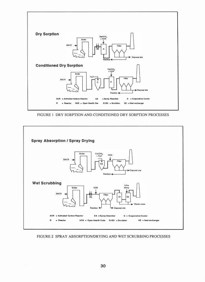
The available gas cleaning processes for the absorption of the acid gaseous pollutants can be classified into the following four groups (see Figures I and 2):
-
-
Figure I • Dry sorption • Conditioned dry sorption
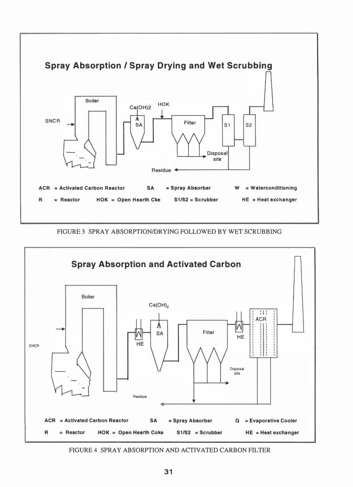
Figure 2 • Spray absorption/drying process • Wet scrubbing
Besides these, there are a number of special types of semi-dry processes. The separation of the reaction products always takes place (except in wet scrubbing) by filtration.
The separation of the fly ash and the metals occurring in the form of particulate matter at the boiler outlet takes place likewise via filtration, so that this process step (again with the exception of wet scrubbing) can be easily integrated into the absorption process for the acid gaseous pollutants.
In the case of wet scrubbing it is naturally sensible to locate dust capture upstream of the wet scrubbing stage.
The separation of dioxins, furans and those metals, in particular mercury, present in gaseous form at the boiler outlet generally takes place by adsorption on activated carbon, zeolites, open hearth furnace coke (HOK), bentonites etc. When special attention must be paid to mercury separation, sodium tetrasulfide can be used to provide higher mercury removal rates(2). For adsorption either static or moving bed adsorbers or filter layer adsorbers may be employed. This variant of adsorption in the filter bag layer again offers the possibility of easy integration of the adsorption process with the filtering
22
out of fly ash and reaction products from the four basic gas cleaning concepts.
Removal of NOx from the flue gases can be performed in conjunction with the above pollution control systems by the use of SNCR (selective non-catalytic reduction) located in the first pass to the boiler. Catalytic processes for DeNOx and dioxin/furan destruction are also possible, but are being reserved for special cases. As an example of one such special case, the operators of Swedish incineration plants are subject to taxation rules which penalize lesser controlled facilities and reward better controlled facilities on the basis of their NOx emissions. The lesser 50% of facilities are obliged to pay a tax of 40 SEK (approx. 5 US$/ton) per ton of NOx emitted annually. This tax, is in turn paid to the better 50% of facilities to offset their cost of NOx controls. As a result, new installations and retrofits with high efficiency SCR plants are currently being planned in Sweden. Generally however a trend to SNCR plants has been observed.
All four gas-cleaning systems (see Figures I and 2) are fundamentally capable of attaining the emission limits existing in the different countries. However, certain restrictions on dry sorption do exist, in that the process demands a lower boiler flue gas temperature, in particular as regards the dioxin/furan and mercury adsorption.
Further, with this process in particular it is necessary to employ relatively expensive absorbents such as NaHCO] or Ca(OHh with a modified pore structure, in order to reduce the sorbent consumption and the quantity of residues produced.
Under the boundary limits presented here, wet scrubbing is undoubtedly the most efficient pollutant capture process and can by appropriate design undercut very significantly the regulatory emission limiting values, as will be demonstrated later in this paper.
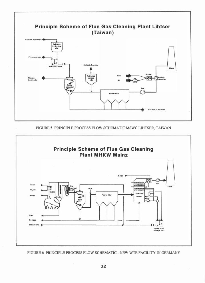
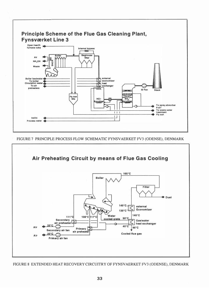
Special boundary conditions can make it necessary to combine the above processes in order to produce new ones, e.g. as in the following combinations (see Figures 3 and 4):
This process serves primarily to enable the operator to run a wet scrubbing process in an effluent-free manner. At the same time this process can, if desired, achieve emission values far below those the new proposed European Union limits, while maintaining the advantage of low sorbent consumption and residual by-products. Scrubbing can be implemented here in one or two stages. The spray absorber/dryer serves either as a pure dryer for
the salts from the scrubber wastewater or as a combined absorber/dryer.
With this process, emission values below or just within the range of detectability can be achieved. The spray absorption is in this process designed for average pollutant contents in the flue gas, since the activated coke filter intercepts gaseous pollutant peaks without any problem due to its enormous buffering capacity. Less sensible heat is thus needed for water evaporation as compared to a simple spray absorption process. Making use of the additional heat before spray absorption and activated carbon filter respectively can significantly increase the boiler efficiency.
Although the four process concepts initially presented are entirely capable of complying with all emission limits, the somewhat more complex combined processes can also justify their existence, in particular where lower emission values than the legal limits must be attained, or where the basic process exists and only needs to be vamped up by a further safe capture stage.
CRITERIA FOR PROCESS SELECTION The main criteria for the selection of the most suitable flue gas cleaning process are
----
---
Emission values Off-gas temperaturelflue gas plume BAT (best available technology) specifications Energy costs/credits Sorbent costs Tipping costs Investment costs Taxes on residues tipped or pollutant emissions
From the above, the total costs for each of the alternatives under review for a given case can be estimated and the most economical variant selected. The number of necessary process stages and/or the operating supplies required (quantity and quality) depend primarily on the gas-side emission values, which must be complied with.
In the USA, new MWCs are typically equipped with spray absorption systems consisting of a spray absorber followed by a fabric filter. This air pollution control system provides Maximum Achievable Control Technology (MACT as defined by US EPA), and can be combined with SNCR and the addition of activated carbon, or a sorbent such as Sorbalit as required. Only in special cases are alternative process configurations used.
In the EC countries, proposals for new plants are being prepared in accordance with the latest draft of the new
23
European Union guideline for the incineration of wastes, which essentially orients itself on the strict limiting values of the German 17th BImSchV. Additionally in the draft of the new guideline a limit for ammonia of 10 mg/ml STP dry (daily average) and 20 mg/m3 STP dry (half-hourly average) is under discussion, referred in each case to 1 1 vol. % O2. This limit can be met using an SNCR (Selective Non-Catalytic Reduction) process, with a normally sufficient DeNOx capability of 40-60 % down to 200 mg/m3 dry referred to 11 vol. % O2, without any special measures.
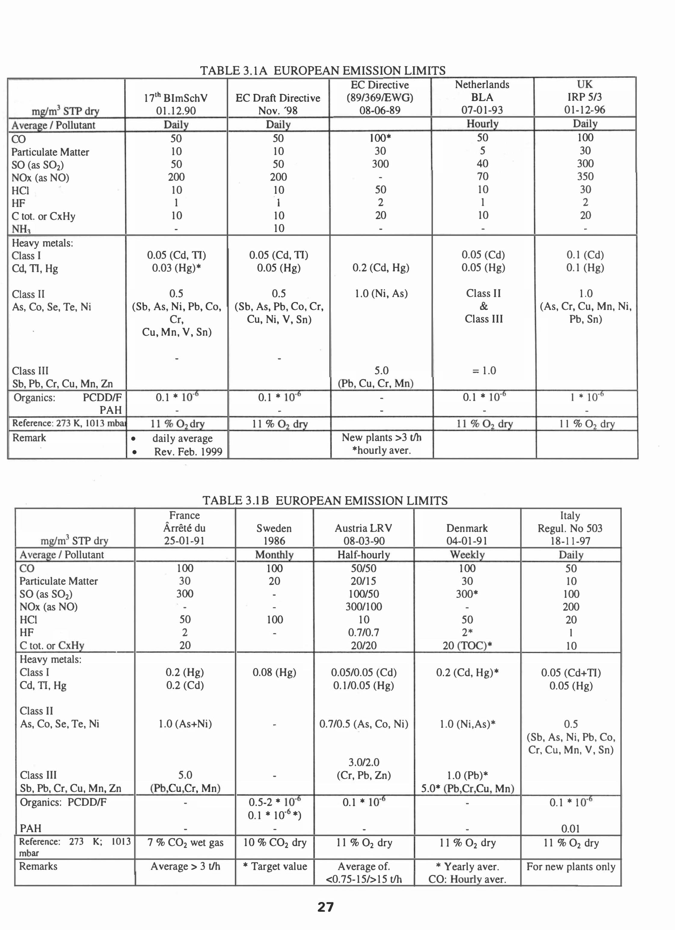
Table 3.1 provides the emission limiting values for a number of countries. The table illustrates that in practically every country the output of dioxins must be reduced to a defined limit value. Usually this is 0.1 ng (TEQ)/m3 STP dry. However, in the U.S. the total concentration of dioxins/furans from MWCs are regulated on a mass basis.
The U.S. EPA limit for large new MWC installations is, after conversion, about 0.2 ng (TEQ)/ml STP dry. (Note should be made that there is no direct conversion between mass and concentration based dioxin standards.) However, a general characteristic of the American legislation is that existing and new plants, and likewise large/small plants, are required to fulfill different emission values (see Table 3.2). Thus, existing old small units, which are equipped only with electrostatic precipitators, need only comply with approx. 1 ng (TEQ)/m3 STP dry. In Asia, the tendency is to base limits generally on those in the EC guidelines of 1989 or the American values - except that the dioxin limit for new installations is fixed at 0.1 ng (TEQ)/ml STP dry, while for older plants it is 0.5 ng (TEQ)/m3 STP dry. The reason for this is above all the enormous dioxin concentrations emitted e.g. by Japanese MWCs.
Throughout Germany, local authorities can issue more stringent emission limits than the federal standards. Fortunately, this occurs only in special individual cases. To comply with the limit values shown in Tables 3.1 and 3.2, without any additional reduction of acid gases, in general a single-stage semi-dry process (i.e. spray dryerlbaghouse) is sufficient. The dioxin and mercury limits can be attained by means of injecting in activated carbon, open-hearth furnace coke or other surface-active additives (e.g. zeolites, clay minerals or Sorbalit).
If single-stage semi-dry processes are operated with high recirculation factors, it may be possible to reduce the dioxins without the addition of activated carbon. For the reduction of mercury in such a case, the employment of a carbon-free sorbent is recommended e.g. Na2S4(2.4).
Wet scrubbers are preferred at locations where effluent may be discharged to an existing wastewater treatment plant and/or if a flue gas plume is permitted, or in the case of larger-capacity plants.
The European NOx limit value of 200 mg/m3 STP dry @ I I % O2 (140 ppmvd @ 7% O2) as a daily average can be complied with using an SNCR plant, which thus finds application as a standard DeNOx measure. With further (more drastic) reductions in the permitted limits for NOx « 140 mg/m3 STP dry @ 11 % O2 (70 ppmvd @ 7% O2), both residue burden (e.g. NH3 content of the fly ash) and ammonia emissions require considering either special measures for decreasing ammonia slip or a SCR process.
In some European countries like Great Britain, Italy and Denmark, the power production or district heating systems are augmented by waste to energy production. In these cases, it is beneficial to maximize steam production by the installation of additional heating surfaces (either an economizer in the boiler area or gas/water heat exchangers). This leads either to dry or wet flue gas cleaning systems, whereby the latter manage to get by without any reheating. In Great Britain, for example, as part of the state NFFO (Non-Fossil Fuel Obligation) program, over the first 15 years of operation electricity is purchased at well over the market price(5). As consequence in new plants there the boiler outlet temperature is lowered down to 285°F (140°C), so that conventional spray absorption methods have to be replaced in favor of modified semi-dry processes.
In particular with smaller plants the use of more expensive sorbents can be favorable in view of the lower investment costs. Thus dry processes on a sodium bicarbonate or modified hydrated lime basis become interesting for plants with a capacity of less than 120,000 tons per year (tpy). As soon as the employment of a calcium-based sorbent is considered for a semi-dry or wet flue gas cleaning plant, in addition the economics of a quicklime slaking system must be considered.
In many countries all over the world, the residue costs play only a subordinate role (Southern Europe, the U.S., and many Asian countries). The residues from spray absorption plants or electrostatic precipitators are deposited above ground in landfills e.g. in the U.S. together with the slag. Only the pH value of the eluates on the TCLP test must lie in the range between 7 and 10 to guarantee adequate retention of the heavy metals (in particular Cd, Pb and Zn). In many Southern European countries and Asia (e.g. in Korea and Taiwan), the mixing of fly ash reaction products from semi-dry flue gas cleaning, cement and further additives to produce a solid material, is considered entirely acceptable. For acceptance, leaching tests have to be performed. Apart
24
from the attainable degree of pollutant capture, this is a further reason why spray absorption is there regarded as the Best Available Technology (BAT).
Another factor is that the capital servicing on investments can be subject to large fluctuations depending upon depreciation period, interest rate and subsidies. In the last analysis the customer must reveal the bases of his evaluation, in order to be able to realize a concept with a minimum total cost.
PROCESS EXAMPLES Typical process concepts fulfilling the above criteria are presented below on the basis of plants currently being executed by BBP Environment.
The Lihtser MSW incineration plant is now being constructed by BBP Environment in Taiwan. It has two combustion trains each capable of burning 330 tons/day. The design data and the guaranteed gas-side emissions are shown in Table 4.1, the process concept is shown in Figure 5.
The basic criteria that led to the selection of this process are the following:
- Compliance with the moderate emission standards - Low tipping costs - High operational reliability - Low maintenance requirement - BAT for Taiwan - based on US standards - A voidance of a steam plume
After the NOx has been reduced by SNCR in the first boiler pass, the flue-gases leave the steam generator at approx. 430 - 480°F (220 - 250°C) and are led to a spray absorber. S02, HCI and HF are absorbed by lime slurry and converted into the respective calcium salts. The required temperature reduction to approx. 290°F (145°C) is effected by addition of internal waste water from the plant. After the spray absorber activated carbon is sprayed through nozzles into the flue gas duct for dioxin and mercury reduction.
The fly ash, the reaction salts and the spent activated carbon are captured in a fabric filter and removed together there. The flue gas is discharged via the ID fan through the system to the stack. Under unfavorable weather conditions the water vapor plume from the stack can be minimized with the aid of an afterburner. The plant will go into operation in the year 2001.
New WTE Facility in Germany The order for the design, supply and construction of a new WTE Facility in Germany was placed in September
1999. The plant consists of two identical lines each with an overall capacity of 400 tons per day of household and commercial/industrial waste.
Within the supply consortium, Babcock Borsig Power is responsible for the flue gas cleaning plant. Start-up is scheduled for the end of 2003.
Criteria for the concept of the flue gas cleaning plant were:
---
-
-
-
Effluent-free operation Low production rate of residues Emission values well below 17th BImSchV (German emission regulation) Safe control of high pollutant concentrations (from commercial/industrial waste) Minimal ammonia concentrations in the residues High availability
The process concept shown in Figure 6 was selected as the optimum solution to the above requirements.
NOx reduction takes place in the first pass of the boiler using a SNCR system. A so-called slip catalyst (DeN Ox) is incorporated in the downstream boiler passes in the area of the economizer. This is the first time such a layout with a catalyst in the raw, dust-laden gas has been realized in a refuse incineration plant. At temperatures from 570°F to 660°F (300°C to 350°C) it enables low NOx emissions and at the same time a low ammonia slip. The latter is necessary to ensure as little ammonia as possible in the bottom ash and fly ash residues, so that they can be used for underground landfill without risk or olfactory nuisance.
The possible risk of a short catalyst service life due to poisoning does not play a significant role here, since at the same location there is an adequate supply of old catalyst material out of a SCR of a dismantled coal fired power station which would have to be disposed of anyway.
Downstream of the boiler the flue gases are cooled down from 730 - 840 OF to 640 OF (390 - 450°C to 340°C). Wastewater from the scrubber is used as cooling agent and sprayed into the spray dryer and at the same time the salts contained therein are dried. Downstream of the spray dryer open-hearth furnace coke dust is sprayed into the flue gas duct for dioxinlfuran and mercury reduction. The fly ash, the reaction salts and the spent coke dust are captured in a fabric filter and disposed of together. In the downstream scrubber HCI and S02 are simultaneously removed by scrubbing with lime slurry. The lime consumption of the scrubber is almost stoichiometrically identical with the quantity of captured
25
acid gas components. The water vapor saturated clean gas is delivered without reheating to the stack.
Design data and expected flue gas emissions are listed in Table 4.2.
In June 1998, BBP Environment received an order for the construction of a third municipal solid waste incineration line at the power station location in Odense, Denmark. The new line will handle 450 tons per day of waste and will begin commercial operations at the end of the year 2000.
The flue gas cleaning system is designed to comply with the more stringent future European emission limits (see Table 3.1). Since effluent discharge is permitted, wet scrubbing produced the optimum concept. The wastewater from the HCl scrubber is subjected to a multi-stage physicochemical treatment, while the alkaline wastewater is supplied to a spray absorber in the power station as make-up water.
A further cost-cutting synergy is the use of the existing boiler feed water plant in the power station for the new line.
The energy efficiency of an incineration plant is regarded as a very important criterion in Denmark(6). For this reason, instead of reheating the flue gas using a gas to gas crossflow heat exchanger, the flue gas temperature at entry to the wet scrubber is reduced by incorporating an economizer which produces additional hot water from the process to preheat the primary air and further increase the steam production of the combustion train.
With this in mind the process concept shown in Figure 7 was developed:
The NOx is controlled with a SNCR system. The flue gas leaves the boiler at a temperature of 330 - 340°F (165 - 170°C) and is cleaned in an entrained-flow fabric filter. Open-hearth coke dust is sprayed into the flue gas duct upstream of the filter to adsorb dioxins and mercury as well as other heavy metals present. Subsequently, the flue gas is cooled down to approx. 285°F (140°C) in the downstream external economizer. A further gas/water heat exchanger lowers the flue gas temperature to approx. 210 OF (99°C). The heated water is used first as cooling water for the water-cooled grate and afterwards for preheating of the combustion air (see Figure 8).
In the downstream acid scrubber HCl is scrubbed out by the addition of water and supplied to a multi-stage effluent treatment system. The S02 is absorbed in the alkaline scrubber by caustic soda solution and supplied
as sodium sulfate solution to the spray absorber of a power station unit as make-up water. The saturated flue gas is delivered without reheating to the stack. The boiler efficiency of the plant is 92.5% at the nominal load point and is thus approx. 10% higher than in conventional plants with 390 - 450°F (200 - 230°C) boiler outlet temperatures. The waste disposal costs stated by the customer are approx. 30 US$/ton of waste.
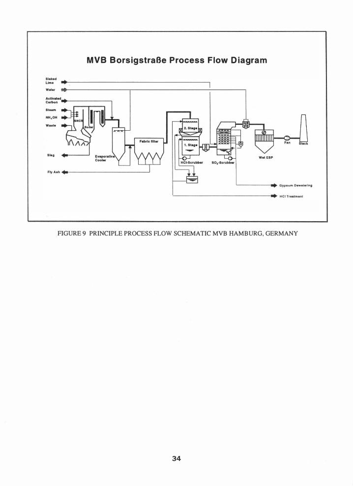
This thermodynamically optimized flue gas cleaning concept represents an advance over the proven flue gas cleaning plant MVB Hamburg (see Figure 9P). The design values and typical emission values of the MVB, which are safely below the legal requirements, are given in Table 4.3.
CONCLUSIONS Since 1990 in Germany there had been a trend of reducing emissions from MWCs without consideration of cost or the impact on energy production. Many plants were built with five to seven individual cleaning steps while producing saleable products for the APC waste stream. Companies in the environmental control industry found that this approach was not transferable to many other countries due to differences in economics and waste management practices.
.
Over the past three years in Germany, there has been general acceptance of MWCs as well as a ban on landfilling of MSW coupled with a considerable change in the overall economic climate, This has lead to the development of more thermally efficient, less expensive and hence more cost effective control technologies without sacrificing the environment. The economic factors that contributed to the reconsideration of the technology development are the high tax rate and the rising cost of solid waste management. The effective date for this ban is in the year 2005 for Germany and 2004 in Austria.
The technologies described in this paper show the wide range of applications that have been developed. These technologies are now being applied around the world to help improve the environmental acceptance while maintaining project economics.
REFERENCES
26
(1) Kubisa, R., Schtittenhelm, W., "Optimierte Konzeptionen fUr Abgasreinigungen hinter Mtillverbrennungsanlagen unter Berticksichtigung wirtschaftlicher Aspekte und Emissionsanforderungen", VDISeminar "Vereinfachte Hightech-Verbesserte Additivtech
Dioxin- und Gesamtemissionsminimierungs-techniken
mit Betriebserfahrungen", Munich, Germany, September 19-20, 1996.
(2) Licata, A., Schtittenhelm, W., Klein, M., "Mercury Control for MWC Using the Sodium Tetrasulfide Process", Eighth Annual North American Waste-to-Energy Conference, Nashville, TN, May 22-24, 2000.
(3) Licata, A., Hartenstein, H.-U., Terracciano, L., "Comparison of U.S. EPA and European Emission Standards for Combustion and Incineration Technologies", Fifth Annual North American Waste-toEnergy Conference, Research Triangle Park, N.C., April 22-25, 1997
(4) Schtittenhelm, W., Hartenstein, H.-U., Licata, A., "An Optimized Concept for Flue Gas Cleaning Downstream of MWCs Using Sodium Tetra Sulfide for Mercury Removal", Sixth Annual North American Waste-to-Energy Conference, Miami, Fl., May, 11- 13, 1998
(5) Williams, P. T., "Waste Treatment and Disposal", published by Wiley & Sons, 1998
(6) Dalager, S., "AusgefUhrte und zuktinftige Rauchgasreinigungstechniken danischer Verbrennungsanlagen", VDI-Seminar BAT- und preisorientierte Dioxin-/ Gesamtemissionsminimierungstechniken fur den europaischen Markt", Munich. Germany, September 17-18, 1998
(7) Zwahr, H., "Konsequenzen fUr die Auslegung einer neuen Abgasreinigungsanlage aufgrund der Erfahrungen bei der MVB Hamburg", VDI-Seminar "Primar und Sekundarseitige Dioxin- und Gesamtemissionsminimierungstechniken, Munich. Germany, September 18-19, 1997.
�STP dry A �I Pollutant CO Particulate Matter SO (as S02) NOx (as NO) HCI HF C tot. or CxHy NH3 Heavy metals: Class I Cd, 11, Hg
Class II As, Co, Se, Te, Ni
•
Class III Sb, Pb, Cr, Cu, Mn, Zn Organics: PCDDIF
PAH Reference: '" I j K, 11111 mb.q Remark
.
mg/m3 STP dry ��I Pollutant CO Particulate Matter SO (as S02) NOx (as NO) HCI HF C tot. or tHy Heavy metals: Class I Cd, TI, Hg
Class II As, Co, Se, Te, Ni
Class III Sb, Pb, (:r Cu, Mn, Zn Organics: PCDDIF
PAH Reference: 273 K; 1013 mbar Remarks
TABLE 3 lA EUROPEAN EMISSION LIMITS •
EC Directive Netherlands 17th BlmSch V EC Draft Directive (89/369IEWG) BLA
01.12.90 Nov. '98 08-06-89 07-01-93 Daily Daily Hour:y
50 50 1 00* 50 10 10 30 5 50 50 300 40
200 200 - 70 10 10 50 10 . 1 I 2 1
10 10 20 10 - 10 - -
0.05 (Cd, 11) 0.05 (Cd, 11) 0.05 (Cd) 0.03 (Hg)* 0.05 (Hg) 0.2 (Cd, Hg) 0.05 (Hg)
0.5 0.5 1.0 (Ni, As) Class II (Sb, As, Ni, Pb, Co, (Sb, As, Pb, Co, Cr, &
•
•
Cr, Cu, Ni, V, Sn) Class III Cu, Mn, V, Sn)
- -5.0 = 1.0
• v, Cu, Cr, r-. 0.1 * 10-0 0.1 * j'Q-O - 0.1 * 10-0
- - - -11%()'( y 11 % ( y 11%()(y daily average New plants >3 tIh Rev. Feb. 1999 *houd aver.
TABLE 3.1B EUROPEAN EMISSION LIMITS France
•
Arrete du Sweden Austria LRV Denmark 25-01-91 1986 08-03-90 04-01-91
. Monthly Hal f" 'lOurl y Weekly 100 100 50150 100 30 20 20115 30
300 - 100150 300* - - 3001100 -
50 100 10 50 2 - 0.7/0.7 2*
20 20120 20 .fOC *
0.2 (Hg) 0.08 (Hg) 0.0510.05 (Cd) 0.2 (Cd, Hg)* 0.2 (Cd) 0.1/0.05 (Hg)
1.0 (As+Ni) - 0.7/0.5 (As, Co, Ni) 1.0 (Ni,As)*
3.0/2.0 5.0 - (Cr, Pb, Zn) 1.0 (Pb)*
( :11 ( :r, Mn 5.0* • u,Cr rll Mn - 0.5-2 * j'Q-O 0.1 * i'Q-O -
0.1 * 10-6 *) - - - -
7 % CO2 wet gas 10 % CO2 dry I I % O2 dry I I %02 dry
Average> 3 tlh * Target value Average of. • Yearly aver. <0.75-151>15 tIh CO: Hom.y aver.
27
UK IRP 5/3
01-12-96 Dail" 100 30
300 350 30 2
20 -
0.1 (Cd) 0.1 (Hg)
1.0 (As, Cr, Cu, Mn, Ni,
Pb, Sn)
I * 10-0 -
II % () y
Italy Regul. No 503
18-11-97 Daily
50 10
100 200 20 I
10
0.05 (Cd+ TI) 0.05 (Hg)
0.5 (Sb, As, Ni, Pb, Co, Cr, Cu, Mn, V, Sn)
0.1 * I u
0.01 11 % O2 dry
For new plants only
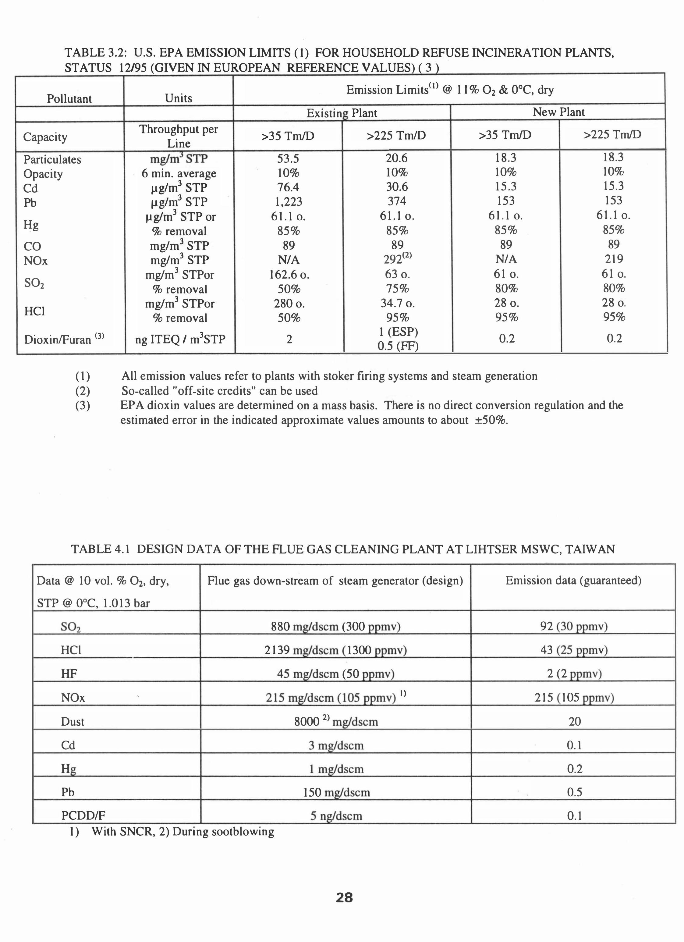
TABLE 3.2: U.S. EPA EMISSION LIMITS ( 1) FOR HOUSEHOLD REFUSE INCINERATION PLANTS, STATUS 12/95 (GIVEN IN EUROPEAN REFERENCE VALUES) ( 3 )
Pollutant Units Emission Limits(l) @ 1 1 % O2 & O°C, dry
Existin Plant New Plant
Capacity Throughput per >35 TmID
Line >225 TmID >35 TmID >225 TmID
Particulates mg/mJSTP 53.5 20.6 18.3 18.3 Opacity 6 min. average
fJg/m3 STP
.. 10% 10% 10% 10% Cd 76.4 30.6 15.3 15.3 Pb fJg/m3 STP 1,223 374 153 153
Hg fJg/m3 STP or 6 1.1 o. 61.1 o. 6 1.1 o. 61.1 o.
% removal 85% 85% 85% 85% CO mg/m3 STP 89 89 89 89 NOx mg/m3 STP N/A 29i2) N/A 219
S02 mg/m3 STPor 162.6 o. 63 o. 61 o. 61 o.
% removal 50% 75% 80% 80%
HCl mg/m3 STPor 280 o. 34.7 o. 28 o. 28 o.
% removal 50% 95% 95% 95%
DioxinlFuran (3) ng ITEQ 1 m3STP 2 1 (ESP) 0.2 0.2 0.5 (FF)
(1) All emission values refer to plants with stoker firing systems and steam generation (2) So-called "off-site credits" can be used (3) EPA dioxin values are determined on a mass basis. There is no direct conversion regulation and the
estimated error in the indicated approximate values amounts to about +50%.
TABLE 4.1 DESIGN DATA OF THE FLUE GAS CLEANING PLANT AT LIHTSER MSWC, TAIWAN
Data @ 10 vol. % O2, dry, Flue gas down-stream of steam generator (design) Emission data (guaranteed)
STP @ O°C, 1.013 bar
;::, 880 (300 pprhv 92 (�() ppmv
HCl 2 139 mg/dscm 1300 ppmv 43 ,,:; ppm v
HF 45 � (50 pprhv 2 (2 ppmv
NOx • 215�105 pr IV I) 215 105 >DIIlV
Dust 8000 2) mddscm 20
Cd 3� 0.1
H 1 m�" 0.2
Pb 150 mg/ds( 0.5
PCDDIF 5� 0.1 • • • 1) With SNCR, 2) Dunng sootblowmg
28
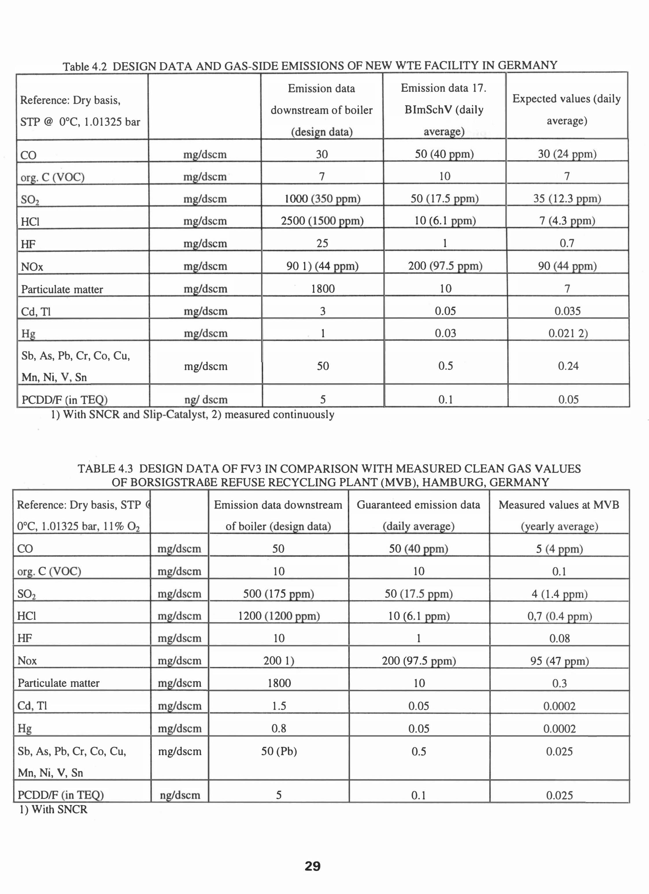
Table 4 2 DESIGN DATA AND GAS-SIDE EMISSIONS OF NEW WTE FACILITY IN GERMANY •
Emission data Emission data 17. Reference: Dry basis,
BImSchV (daily Expected values (daily
downstream of boiler STP @ OCC, 1.01325 bar average)
�data average
CO �ds 30 50 40 ppm 30 '?4�
�C'VOC: mg/dsc 7 10 7
SO, mg/dscm 1000 '1'i0 ppm 50 17.5 ppu 35 12.3 ppm
HCI m:�/dscm 2500 15OO� 10 f6.1 ppm 7 4.3 pr
HF m�/dscm 25 1 0.7
NOx � 90 1 44 ppm) 200 l�/.5� 90 44�
Particulate matter mg/ds( 1800 10 7
Cd, TI � 3 0.05 0.035
Hg �.., 1 0.03 0.021 2
Sb, As, Pb, Cr, Co, Cu,
Mn, Ni, V! Sn mg/dscm 50 0.5 0.24
PCDDIF :in T � ��dscm 5 0.1 0.05 • • 1) With SNCR and Shp-Catalyst, 2) measured continuously
•
TABLE 4.3 DESIGN DATA OF FV3 IN COMPARISON WITH MEASURED CLEAN GAS VALUES OF BORSIGSTRABE REFUSE RECYCLING PLANT (MVB), HAMBURG, GERMANY
Reference: Dry basis, STP Emission data downstream Guaranteed emission data Measured values at MVB
OCC, 1.01325 bar_, 11 % 0, of boiler :design data; :daiIyaverage: (yearly average
CO �l 50 50 40.£EE!) 5 4.£EE!)
or:;. C 'VOC: mg/dscm 10 10 0.1
SO � 500 175 p� 50 17.5.£EE!) 4 1.4 ppm
HCI � 1200 12oo� 10 :6.1 ppm 0,7 0 4 �I
HF mg/dscm 10 1 0.08
Nox �dscm 200 1 200 YI.5 p� 95 47 ppm
Particulate matter J!)g'-d_s<; m 1800 10 0.3
rn TI ..!!!8!rlsc 1.5 0.05 0.0002
Hg m: . /.J. l�/Uscm 0.8 0.05 0.0002
Sb, As, Pb, Cr, Co, Cu, mg/dscm 50 (Pb) 0.5 0.025
Mn, NI, V, Sn
PCDDIF n� '/dscm 5 0.1 0.025 • 1) With SNCR
29
Dry Sorption Boller
SNCA
Conditioned Dry Sorption
Bolle,
SNCA
ACA • Actln'ad Carbon R •• ctor
'--'---'.,....... Disposal Sl18
L-...l........I..-rl�DI.poo.1 .n. A •• ldu. + ___ ..1
SA • Spray Abaorber Q • Ev.por.tI .... Coo'"
R • A.Ktor HOK . Opan H.arth eke 511$2 • Scrubber HE. H .. , uchangar
FIGURE 1 DRY SORPTION AND CONDITIONED DRY SORPTION PROCESSES
Spray Absorption I Spray Drying
Boiler
SNCR
Wet Scrubbing
SNCR
Ca(OH), +HzO HOK
'--'--'--.-�Oisposal site
ACR • Activated Carbon R •• ctor SA • Spray Abaorba, Q • Evaporative Cool.r
R • Reactor HOK • Open H •• rth Coke S11S2 . Scrubber
FIGURE 2 SPRAY ABSORPTIONIDRYING AND WET SCRUBBING PROCESSES
30
Spray Absorption I Spray Drying and Wet Scrubbing
5NCR
Boiler
- . I =.l
Filter 51
'----'-----'-. Disposal site
52
Residue +-_____ ---''--_.....J
ACR = Activated Carbon Reactor SA = Spray Absorber W = Watercondltlonlng
R
SNCR
= Reactor HOK = Open Hearth Cke Sl/S2 = Scrubber HE = Heat exchanger
FIGURE 3 SPRAY ABSORPTIONIDRYING FOLLOWED BY WET SCRUBBING
Spray Absorption and Activated Carbon
Boiler
-. I j Residue
Ca(OHh
Filter
Disposal site
ACR = Activated Carbon Reactor SA = Spray Absorber Q = Evaporative Cooler
R = Reactor HOK = Open Hearth Coke Sl/S2 = Scrubber HE = Heat exchanger
FIGURE 4 SPRAY ABSORPTION AND ACTIVATED CARBON FILTER
31
Principle Scheme of Flue Gas Cleaning Plant Lihtser (Taiwan)
Flu. g .. 'rom boiler
Fuel
Air
R •• ldua to dlapo •• '
FIGURE 5 PRINCIPLE PROCESS FLOW SCHEMATIC MSWC LIHTSER, T AIW AN
SI .. m
w .. t.
Ullk 01 lima
Principle Scheme of Flue Gas Cleaning Plant MHKW Mainz
Spray dry., atorag' tank
Stack
FIGURE 6 PRINCIPLE PROCESS FLOW SCHEMATIC - NEW WTE FACILITY IN GERMANY
32
Principle Scheme of the Flue Gas Cleaning Plant, Fynsvmrket Line 3
Open hearth furnace coke
Air
NH,OH
WI.tl
-----f9'1 external
To .pray ablorber Fv07
L-___ .--JL-.:....:......:...-_______ � To wa.te water treatment
L-_________ --:-�--------. Fly ash
NaOH .... ----------IJ I Proce.1 water ot"�-----------------.l.· ---l·
FIGURE 7 PRINCIPLE PROCESS FLOW SCHEMATIC FYNSV AERKET FV3 (ODENSE), DENMARK
Air Preheating Circuit by means of Flue Gas Cooling
Air
Air
Secondary �t---air preheater l..:!6:i---
Secondary air fan
Primary air fan
'--....1..._'--_-+ Dust
external Economizer
................... ..JI.'-'IWI.......:..:.....:F...-J Gas/water
Cooled flue gas
FIGURE 8 EXTENDED HEAT RECOVERY CIRCUITRY OF FYNSV AERKET FV3 (ODENSE), DENMARK
33
MVB BorsigstraBe Process Flow Diagram
Slak.d • Lime
Wat.r
Carbon
St.am
NH.OH
Wa.t.
Slag
F�A.h��--------------------�
'---------_ Gypsum Oewat.rlng
'-----------------------------_ He! Tr.atmant
FIGURE 9 PRINCIPLE PROCESS FLOW SCHEMATIC MVB HAMBURG, GERMANY
34