Embed Size (px)
Citation preview

IOP Conference Series Materials Science and Engineering
OPEN ACCESS
New trends in antenna design transformationoptics approachTo cite this article P H Tichit et al 2013 IOP Conf Ser Mater Sci Eng 44 012012
View the article online for updates and enhancements
You may also likeLow-cost array antenna design for S-Bandmaritime radar by using sparse arraymethodEfri Sandi Ratna Addafiah and PitoyoYuliatmojo
-
Small Evolution Antenna Design MethodBased on Dynamic Hill Climbing Algorithmand Orthogonal ExperimentHui Shi Junjie Li and Zhiming Xie
-
The 4times4 hybrid L-slotted rectangularmicrostrip antenna for dual band wificommunicationRamaska Prima Agusta Heroe WijantoBudi Syihabuddin et al
-
This content was downloaded from IP address 61142105122 on 08022022 at 0833
New trends in antenna design transformation optics
approach
P H Tichit1 S N Burokur
123 and A de Lustrac
12
1 IEF Univ Paris-Sud CNRS UMR 8622 91405 Orsay cedex France
2 Univ Paris-Ouest 92410 Ville drsquoAvray France
E-mail shah-nawazburokuru-psudfr
Abstract Transformation optics is an emerging field offering a powerful and unprecedented
ability to manipulate and control electromagnetic waves Using this tool we demonstrate the
design of novel antenna concepts by tailoring their radiation properties The wave manipulation
is enabled through the use of engineered dispersive composite metamaterials that realize a
space coordinate transformation Numerical simulations together with experimental
measurements are performed in order to validate the coordinate transformation concept Near-
field cartography and far-field pattern measurements performed on fabricated prototypes agree
qualitatively with Finite Element Method (FEM) simulations It is shown that a particular
radiation pattern can be tailored at ease into a desired one by modifying the electromagnetic
properties of the space around the radiating element This idea opens the way to novel antenna
design techniques for various application domains such as aeronautical and transport fields
1 Introduction
Transformation optics or transformation electromagnetics (also called coordinate transformation) is a
powerful mathematical tool that is used to generate a new transformed space from an initial one where
solutions of Maxwellrsquos equations are known by manipulating electromagnetic waves As a first step it
consists in imagining a virtual space with desired topological properties which will contain the
underlying physics This approach has been revived when J B Pendry et al [1] have proposed an
interpretation where permeability and permittivity tensors components can be viewed as a material in
the original space It is as if the new material mimicks the defined topological space Since this
pioneering work of J B Pendry and that of U Leonhardt et al [2] transformation optics is an
emerging field where Maxwellrsquos equations are form invariant under a coordinate transformation It
offers an unconventional strategy to the design of novel class metamaterial devices The most striking
application conceived so far via coordinate transformation concept is the invisibility cloak [3]
Concerning antenna applications focusing lens antennas [4-6] and the engineering of radiation
patterns [7] have been proposed The performances of an omnidirectional retroreflector [8] and
Luneberg lenses [9] have also been experimentally demonstrated An octave-bandwidth horn antenna
has been experimentally validated for satellite communications [10] Recently techniques of source
transformation [11-13] have offered new opportunities for the design of active devices with source
distribution included in the transformed space
3 To whom any correspondence should be addressed
Radio and Antenna Days of the Indian Ocean (RADIO 2012) IOP PublishingIOP Conf Series Materials Science and Engineering 44 (2013) 012012 doi1010881757-899X441012012
Published under licence by IOP Publishing Ltd 1
Using this last approach we review the design of three antennas where the radiation pattern is
tailored specifically in each case The first one concerns an ultra-directive antenna obtained by
stretching a source into an extended coherent radiator [14-16] which is implemented through the use
of judiciously engineered metamaterials and the device is shown experimentally to produce an ultra-
directive emission The idea has been extended to a second device a wave bending one [17] so as to
achieve a steered beam antenna via a rotational coordinate transformation Experimental
measurements have shown a beam steering as much as 66deg Finally we present the numerical design
of a quasi-isotropic antenna achieved by expanding the space around a directive source [18]
2 Ultra-directive antenna
The ultra-directive antenna is based on the transformation of a cylindrical space into a rectangular one
The schematic principle of the transformation is presented in figure 1(a) The theoretical underlying
physics of the transformation involved here has been detailed recently in [14] The concept is as
follows the imagined space of our proposed antenna is obtained by transforming a flat isotropic
cylindrical half-space with zero Riemann curvature tensor described in polar coordinates r into a
flat space in squeezed Cartesian coordinates xrsquo yrsquo and zrsquo are the coordinates in the virtual transformed
rectangular space and x y z are those in the initial real cylindrical space We assume free space in the
cylinder with isotropic permeability and permittivity tensors 0 and 0 In [15] we have shown that
the coordinate transformation can be implemented by a material described with e = 015 m and L =
005 m by 1xx 2
1
xx
yy
and 24 xxzz
(a)
(b)
(c)
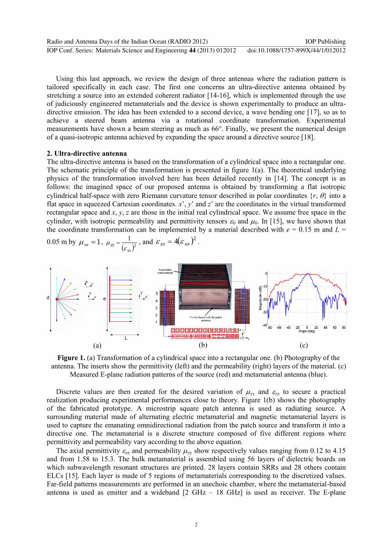
Figure 1 (a) Transformation of a cylindrical space into a rectangular one (b) Photography of the
antenna The inserts show the permittivity (left) and the permeability (right) layers of the material (c)
Measured E-plane radiation patterns of the source (red) and metamaterial antenna (blue)
Discrete values are then created for the desired variation of yy and zz to secure a practical
realization producing experimental performances close to theory Figure 1(b) shows the photography
of the fabricated prototype A microstrip square patch antenna is used as radiating source A
surrounding material made of alternating electric metamaterial and magnetic metamaterial layers is
used to capture the emanating omnidirectional radiation from the patch source and transform it into a
directive one The metamaterial is a discrete structure composed of five different regions where
permittivity and permeability vary according to the above equation
The axial permittivity zz and permeability yy show respectively values ranging from 012 to 415
and from 158 to 153 The bulk metamaterial is assembled using 56 layers of dielectric boards on
which subwavelength resonant structures are printed 28 layers contain SRRs and 28 others contain
ELCs [15] Each layer is made of 5 regions of metamaterials corresponding to the discretized values
Far-field patterns measurements are performed in an anechoic chamber where the metamaterial-based
antenna is used as emitter and a wideband [2 GHz ndash 18 GHz] is used as receiver The E-plane
Radio and Antenna Days of the Indian Ocean (RADIO 2012) IOP PublishingIOP Conf Series Materials Science and Engineering 44 (2013) 012012 doi1010881757-899X441012012
2
radiation pattern is measured at 106 GHz Figure 1(c) presents the comparison between simulations
and experiments for the patch source alone and the metamaterial antenna The transformation of the
patchrsquos omnidirectional radiation into a directive is clearly established A narrow half-power
beamwidth of 13deg is observed for the measured antenna
3 Steered beam antenna
We consider a source radiating in a rectangular space Theoretically this radiation emitted from the
latter source can be transformed into an azimuthal one using transformation optics The transformation
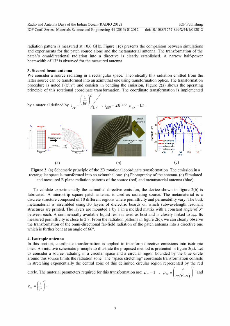
procedure is noted F(xrsquoyrsquo) and consists in bending the emission Figure 2(a) shows the operating
principle of this rotational coordinate transformation The coordinate transformation is implemented
by a material defined by 71
21
brrrε 82
θθε and 71
zzμ
(a)
(b)
(c)
Figure 2 (a) Schematic principle of the 2D rotational coordinate transformation The emission in a
rectangular space is transformed into an azimuthal one (b) Photography of the antenna (c) Simulated
and measured E-plane radiation patterns of the source (red) and metamaterial antenna (blue)
To validate experimentally the azimuthal directive emission the device shown in figure 2(b) is
fabricated A microstrip square patch antenna is used as radiating source The metamaterial is a
discrete structure composed of 10 different regions where permittivity and permeability vary The bulk
metamaterial is assembled using 30 layers of dielectric boards on which subwavelength resonant
structures are printed The layers are mounted 1 by 1 in a molded matrix with a constant angle of 3deg
between each A commercially available liquid resin is used as host and is closely linked to Its
measured permittivity is close to 28 From the radiation patterns in figure 2(c) we can clearly observe
the transformation of the omni-directional far-field radiation of the patch antenna into a directive one
which is further bent at an angle of 66deg
4 Isotropic antenna
In this section coordinate transformation is applied to transform directive emissions into isotropic
ones An intuitive schematic principle to illustrate the proposed method is presented in figure 3(a) Let
us consider a source radiating in a circular space and a circular region bounded by the blue circle
around this source limits the radiation zone The ldquospace stretchingrdquo coordinate transformation consists
in stretching exponentially the central zone of this delimited circular region represented by the red
circle The material parameters required for this transformation are 1rr
2
)(
rqr
r and
2
r
rzz
Radio and Antenna Days of the Indian Ocean (RADIO 2012) IOP PublishingIOP Conf Series Materials Science and Engineering 44 (2013) 012012 doi1010881757-899X441012012
3
(a)
(b)
Figure 3 (a) Schematic principle of the space stretching coordinate transformation (b) Simulated E-
plane radiation patterns of the source (blue) and metamaterial antenna (red)
Numerical simulations show that a quasi-perfect isotropic emission can be effectively achieved
when a high value is used for the expansion factor q
5 Conclusion
To summarize we have shown how coordinate transformation can be applied to manipulate and
control electromagnetic waves at will in order to tailor desired radiation patterns in the antenna fields
Experimental measurements performed on the directive and beam steerable antennas have shown
concluding results making these devices compatible for aeronautical and transport domains
References
[1] Pendry J B Schurig D and Smith D R 2006 Science 312 1780
[2] Leonhardt U 2006 Science 312 1777
[3] Schurig D Mock J J Justice B J Cummer S A Pendry J B Starr A F and Smith D R 2006
Science 314 977
[4] Jiang W X Cui T J Ma H F Yang X M and Cheng Q 2008 Appl Phys Lett 93 221906
[5] Mei Z L Bai J Niu T M and Cui T J 2010 PIER M 13 261
[6] Jiang Z H Gregory M D and Werner D H 2011 Phys Rev B 84 165111
[7] Garcia-meca C Martinez A and Leonhardt U 2011 Opt Express 19 23743
[8] Ma Y G Ong C K Tyc T and Leonhardt U 2009 Nat Mater 8 639
[9] Kundtz N and Smith D R 2010 Nat Mater 9 129
[10] Lier E Werner D H Scarborough C P Wu Q and Bossard J A 2011 Nat Mater 10 216
[11] Luo Y Zhang J Ran L Chen H and Kong J A 2008 PIERS Online 4 795
[12] Allen J Kundtz N Roberts D A Cummer S A and Smith D R 2009 Appl Phys Lett 94
194101
[13] Popa B I Allen J and Cummer S A 2009 Appl Phys Lett 94 244102
[14] Tichit P H Burokur S N and de Lustrac A 2009 J Appl Phys 105 104912
[15] Tichit P H Burokur S N Germain D and de Lustrac A 2011 Phys Rev B 83 155108
[16] Tichit P H Burokur S N Germain D and de Lustrac A 2011 Elec Lett 47 580
[17] Wu X Tichit P H Burokur S N Kirouane S Sellier A and de Lustrac A 2012 Microwave Opt
Technol Lett 54 2536
[18] Tichit P H Burokur S N and de Lustrac A 2011 Opt Express 19 20551
Radio and Antenna Days of the Indian Ocean (RADIO 2012) IOP PublishingIOP Conf Series Materials Science and Engineering 44 (2013) 012012 doi1010881757-899X441012012
4

New trends in antenna design transformation optics
approach
P H Tichit1 S N Burokur
123 and A de Lustrac
12
1 IEF Univ Paris-Sud CNRS UMR 8622 91405 Orsay cedex France
2 Univ Paris-Ouest 92410 Ville drsquoAvray France
E-mail shah-nawazburokuru-psudfr
Abstract Transformation optics is an emerging field offering a powerful and unprecedented
ability to manipulate and control electromagnetic waves Using this tool we demonstrate the
design of novel antenna concepts by tailoring their radiation properties The wave manipulation
is enabled through the use of engineered dispersive composite metamaterials that realize a
space coordinate transformation Numerical simulations together with experimental
measurements are performed in order to validate the coordinate transformation concept Near-
field cartography and far-field pattern measurements performed on fabricated prototypes agree
qualitatively with Finite Element Method (FEM) simulations It is shown that a particular
radiation pattern can be tailored at ease into a desired one by modifying the electromagnetic
properties of the space around the radiating element This idea opens the way to novel antenna
design techniques for various application domains such as aeronautical and transport fields
1 Introduction
Transformation optics or transformation electromagnetics (also called coordinate transformation) is a
powerful mathematical tool that is used to generate a new transformed space from an initial one where
solutions of Maxwellrsquos equations are known by manipulating electromagnetic waves As a first step it
consists in imagining a virtual space with desired topological properties which will contain the
underlying physics This approach has been revived when J B Pendry et al [1] have proposed an
interpretation where permeability and permittivity tensors components can be viewed as a material in
the original space It is as if the new material mimicks the defined topological space Since this
pioneering work of J B Pendry and that of U Leonhardt et al [2] transformation optics is an
emerging field where Maxwellrsquos equations are form invariant under a coordinate transformation It
offers an unconventional strategy to the design of novel class metamaterial devices The most striking
application conceived so far via coordinate transformation concept is the invisibility cloak [3]
Concerning antenna applications focusing lens antennas [4-6] and the engineering of radiation
patterns [7] have been proposed The performances of an omnidirectional retroreflector [8] and
Luneberg lenses [9] have also been experimentally demonstrated An octave-bandwidth horn antenna
has been experimentally validated for satellite communications [10] Recently techniques of source
transformation [11-13] have offered new opportunities for the design of active devices with source
distribution included in the transformed space
3 To whom any correspondence should be addressed
Radio and Antenna Days of the Indian Ocean (RADIO 2012) IOP PublishingIOP Conf Series Materials Science and Engineering 44 (2013) 012012 doi1010881757-899X441012012
Published under licence by IOP Publishing Ltd 1
Using this last approach we review the design of three antennas where the radiation pattern is
tailored specifically in each case The first one concerns an ultra-directive antenna obtained by
stretching a source into an extended coherent radiator [14-16] which is implemented through the use
of judiciously engineered metamaterials and the device is shown experimentally to produce an ultra-
directive emission The idea has been extended to a second device a wave bending one [17] so as to
achieve a steered beam antenna via a rotational coordinate transformation Experimental
measurements have shown a beam steering as much as 66deg Finally we present the numerical design
of a quasi-isotropic antenna achieved by expanding the space around a directive source [18]
2 Ultra-directive antenna
The ultra-directive antenna is based on the transformation of a cylindrical space into a rectangular one
The schematic principle of the transformation is presented in figure 1(a) The theoretical underlying
physics of the transformation involved here has been detailed recently in [14] The concept is as
follows the imagined space of our proposed antenna is obtained by transforming a flat isotropic
cylindrical half-space with zero Riemann curvature tensor described in polar coordinates r into a
flat space in squeezed Cartesian coordinates xrsquo yrsquo and zrsquo are the coordinates in the virtual transformed
rectangular space and x y z are those in the initial real cylindrical space We assume free space in the
cylinder with isotropic permeability and permittivity tensors 0 and 0 In [15] we have shown that
the coordinate transformation can be implemented by a material described with e = 015 m and L =
005 m by 1xx 2
1
xx
yy
and 24 xxzz
(a)
(b)
(c)
Figure 1 (a) Transformation of a cylindrical space into a rectangular one (b) Photography of the
antenna The inserts show the permittivity (left) and the permeability (right) layers of the material (c)
Measured E-plane radiation patterns of the source (red) and metamaterial antenna (blue)
Discrete values are then created for the desired variation of yy and zz to secure a practical
realization producing experimental performances close to theory Figure 1(b) shows the photography
of the fabricated prototype A microstrip square patch antenna is used as radiating source A
surrounding material made of alternating electric metamaterial and magnetic metamaterial layers is
used to capture the emanating omnidirectional radiation from the patch source and transform it into a
directive one The metamaterial is a discrete structure composed of five different regions where
permittivity and permeability vary according to the above equation
The axial permittivity zz and permeability yy show respectively values ranging from 012 to 415
and from 158 to 153 The bulk metamaterial is assembled using 56 layers of dielectric boards on
which subwavelength resonant structures are printed 28 layers contain SRRs and 28 others contain
ELCs [15] Each layer is made of 5 regions of metamaterials corresponding to the discretized values
Far-field patterns measurements are performed in an anechoic chamber where the metamaterial-based
antenna is used as emitter and a wideband [2 GHz ndash 18 GHz] is used as receiver The E-plane
Radio and Antenna Days of the Indian Ocean (RADIO 2012) IOP PublishingIOP Conf Series Materials Science and Engineering 44 (2013) 012012 doi1010881757-899X441012012
2
radiation pattern is measured at 106 GHz Figure 1(c) presents the comparison between simulations
and experiments for the patch source alone and the metamaterial antenna The transformation of the
patchrsquos omnidirectional radiation into a directive is clearly established A narrow half-power
beamwidth of 13deg is observed for the measured antenna
3 Steered beam antenna
We consider a source radiating in a rectangular space Theoretically this radiation emitted from the
latter source can be transformed into an azimuthal one using transformation optics The transformation
procedure is noted F(xrsquoyrsquo) and consists in bending the emission Figure 2(a) shows the operating
principle of this rotational coordinate transformation The coordinate transformation is implemented
by a material defined by 71
21
brrrε 82
θθε and 71
zzμ
(a)
(b)
(c)
Figure 2 (a) Schematic principle of the 2D rotational coordinate transformation The emission in a
rectangular space is transformed into an azimuthal one (b) Photography of the antenna (c) Simulated
and measured E-plane radiation patterns of the source (red) and metamaterial antenna (blue)
To validate experimentally the azimuthal directive emission the device shown in figure 2(b) is
fabricated A microstrip square patch antenna is used as radiating source The metamaterial is a
discrete structure composed of 10 different regions where permittivity and permeability vary The bulk
metamaterial is assembled using 30 layers of dielectric boards on which subwavelength resonant
structures are printed The layers are mounted 1 by 1 in a molded matrix with a constant angle of 3deg
between each A commercially available liquid resin is used as host and is closely linked to Its
measured permittivity is close to 28 From the radiation patterns in figure 2(c) we can clearly observe
the transformation of the omni-directional far-field radiation of the patch antenna into a directive one
which is further bent at an angle of 66deg
4 Isotropic antenna
In this section coordinate transformation is applied to transform directive emissions into isotropic
ones An intuitive schematic principle to illustrate the proposed method is presented in figure 3(a) Let
us consider a source radiating in a circular space and a circular region bounded by the blue circle
around this source limits the radiation zone The ldquospace stretchingrdquo coordinate transformation consists
in stretching exponentially the central zone of this delimited circular region represented by the red
circle The material parameters required for this transformation are 1rr
2
)(
rqr
r and
2
r
rzz
Radio and Antenna Days of the Indian Ocean (RADIO 2012) IOP PublishingIOP Conf Series Materials Science and Engineering 44 (2013) 012012 doi1010881757-899X441012012
3
(a)
(b)
Figure 3 (a) Schematic principle of the space stretching coordinate transformation (b) Simulated E-
plane radiation patterns of the source (blue) and metamaterial antenna (red)
Numerical simulations show that a quasi-perfect isotropic emission can be effectively achieved
when a high value is used for the expansion factor q
5 Conclusion
To summarize we have shown how coordinate transformation can be applied to manipulate and
control electromagnetic waves at will in order to tailor desired radiation patterns in the antenna fields
Experimental measurements performed on the directive and beam steerable antennas have shown
concluding results making these devices compatible for aeronautical and transport domains
References
[1] Pendry J B Schurig D and Smith D R 2006 Science 312 1780
[2] Leonhardt U 2006 Science 312 1777
[3] Schurig D Mock J J Justice B J Cummer S A Pendry J B Starr A F and Smith D R 2006
Science 314 977
[4] Jiang W X Cui T J Ma H F Yang X M and Cheng Q 2008 Appl Phys Lett 93 221906
[5] Mei Z L Bai J Niu T M and Cui T J 2010 PIER M 13 261
[6] Jiang Z H Gregory M D and Werner D H 2011 Phys Rev B 84 165111
[7] Garcia-meca C Martinez A and Leonhardt U 2011 Opt Express 19 23743
[8] Ma Y G Ong C K Tyc T and Leonhardt U 2009 Nat Mater 8 639
[9] Kundtz N and Smith D R 2010 Nat Mater 9 129
[10] Lier E Werner D H Scarborough C P Wu Q and Bossard J A 2011 Nat Mater 10 216
[11] Luo Y Zhang J Ran L Chen H and Kong J A 2008 PIERS Online 4 795
[12] Allen J Kundtz N Roberts D A Cummer S A and Smith D R 2009 Appl Phys Lett 94
194101
[13] Popa B I Allen J and Cummer S A 2009 Appl Phys Lett 94 244102
[14] Tichit P H Burokur S N and de Lustrac A 2009 J Appl Phys 105 104912
[15] Tichit P H Burokur S N Germain D and de Lustrac A 2011 Phys Rev B 83 155108
[16] Tichit P H Burokur S N Germain D and de Lustrac A 2011 Elec Lett 47 580
[17] Wu X Tichit P H Burokur S N Kirouane S Sellier A and de Lustrac A 2012 Microwave Opt
Technol Lett 54 2536
[18] Tichit P H Burokur S N and de Lustrac A 2011 Opt Express 19 20551
Radio and Antenna Days of the Indian Ocean (RADIO 2012) IOP PublishingIOP Conf Series Materials Science and Engineering 44 (2013) 012012 doi1010881757-899X441012012
4