Embed Size (px)
Citation preview

NEW THIN FILM SINGLE SCREW VENTING MECHANISM TESTED ON 30% WOOD FLOUR/PELLETS, 35% CALCIUM CARBONATE/PP PELLETS
AND UNDRIED PMMA
Keith Luker, Randcastle Extrusion Systems, Inc., Cedar Grove, NJ
Abstract
A new single screw mixing/venting element was tested. This element combines unique properties. First, the mixing/venting element makes a thin film over a large surface area at near zero pressure. Such thin films transported under barrel vent openings can efficiently extract volatiles, air or water. Second, each mixing/venting element creates multiple elongational flow fields—the key to good compounding. Since the pressure is near zero, heat generated by mixing is very low. Third, the entire mixing/venting element melts polymer in an axial length of only 3 or 4 L/Ds. Therefore, a 36/1 single screw extruder can then have 3 vents and the first mixing/venting element substantially melts the polymer. The mechanism allows the removal of volatiles during the melting process. It should be noted that removing moisture from some materials during the melting process can limit hydrolysis. Fourth, this mixing/venting element is also a melt separation screw somewhat similar to a barrier screw but without the need of high pressure (and consequent heat generation) or high compression (causing agglomeration before mixing). Rather than restraining material by means of a barrier, the mixing/venting/melting element forwards material and high output is achieved. A 1 inch single screw extruder was built with three venting/mixing elements and one vents over each element. Three materials were tested. Undried PMMA pellets were processed for moisture removal by looking for any sign of bubbles in the strands and with an emphasis on achieving a high output rate. Output rates were 18.4 pounds per hour with one or two vents and 17.0 with three vents. There was no vent flow at these outputs and there were no indications of moisture in the clear strands or on the surface. 35 MI PP pellets, 2% black concentrate and 35% calcium carbonate powder were processed to make sure that
entrained air could be removed and that the strand would be smooth—indicating good mixing. The mixture was processed into strands and pelletized. There were no signs of entrained air and the surface is smooth and shown at 100 times magnification. LDPE, PP and HDPE, all pellets, were processed with undried wood flour at up to 30% by weight. Three atmospheric vents were used to degas the wood of moisture and volatiles. Since this was a single screw extruder, no gear pump was necessary to achieve high pressures or stable flow. The materials were processed, without any processing aides, directly into smooth, 30 mil, glossy sheet. This new element extends the utility of single screw extruders by allowing more vents in a shorter axial length than conventional screws; it allows for degassing even during the melting; it creates a large thin film for efficient degassing in each element; it is a high output melting mechanism and a melt separation element. Finally, it showed compounding of wood and calcium carbonate at up to 35%. The element does not change the primary advantages of the single screw extruder: economy, high output, high stable pressures and low cost but extends its usefulness into the range of multi-screw extruders. Multi-screw extruders sometimes call this, “direct-extrusion”—meaning compounding while making a shape other than pellets but this requires a gear pump. Since the precursor invention showed good mixing of immiscible blends in the submicron range (without a compatibilizer and the same size domains at multi-screw extruders) and with nano-particulates even at 50,000 to 100,000 times magnification (where pictures even from multi-screw machines are rare), the new screw elements should be of significant benefit.
Introduction
Historically, single screw extruders have been pumps first and compounders and degassers second.
Single screw mixers, or compounders, have lagged because they have lacked the multiple elongational flow

fields of multi-screw extruders, simple upstream axial mixing, and the ability to degas during mixing.
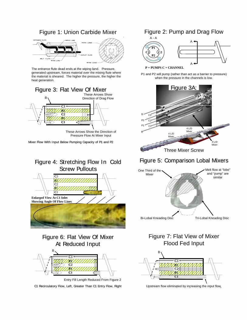
Figure 3 and 3A show a more useful arrangement of
channels and pumps in the “Recirculator” [12] (hereafter) mixer. One third of the mixer, circumferentially, is “laid flat” in Figure 3, show between flights and would be duplicated three times. This is useful in that, just as in multiple flights, melting, mixing and degassing benefit from processing in smaller amounts. Conceptually, this particular mixer is shown after melting in the typical downstream position near the end of the screw though typically preceded by 1 to 3 other mixers as in Figure 3A. The flat section is bounded by a tight fitting boundary, B (similar in clearance to a typical flight).
As degassers, single screws have lagged because degassing did not occur during mixing and so lacked the superior surface renewal of multi-stage screws. Further, multi-screw twins commonly use multiple vents to sufficiently extract gases. Often one is a coarse vent and two are for fine degassing. But single screws have lagged because the second stage of a two stage screw uses about 12 L/D’s (~6 L/D pumping, 1 L/D compression, 4 L/D venting, 1 L/D decompression) of axial length—often practically limiting singles to one vent.
The UC mixer, Figure 1, is typical of a fluted mixer that after melting, pumps material through a shear plane. The design requires a relatively high input pressure to overcome the resistance of the entry flute (since it dead ends) and the resistance of the mixing land.
Figure 3 shows an input flow from the flights on the
right and flowing to the left as indicated by the arrows. In this case, the input flow is set substantially below the pumping rate of the P1 and P2 pumps either by a separate upstream starve feeder or by screw geometry (such as shallow input channels or narrow pitch) ahead of the mixer.
It is well known that elongational forces are more effective for dispersive mixing than shear [1]. Some attempts have been made to induce elongation in single screw extruders such as by a shaped pin [2].
Flow in the input channel will be a combination of the pressure flow in the axial direction and drag flow in the cross axial direction. The combination continuously stretches the flow as the viscous material is pushed down the channel, where it will flow spirally, and pulled by the pumps. A cold screw pullout shows the angle of lines from a pigmented PP frozen on the screw in Figure 4. The stretching flow in most of the channel may be visualized continually unwrapping a spiral roll of “fluid paper.”
Upstream axial mixing conveys material from a
downstream to an upstream position along the screw such as by a screw within a screw [3] or a downstream flow passageway that leads upstream.
Various methods of venting in a single screw
extruder are known [5] as are multiple flights in the extraction section for improved surface renewal [6].
Generally, the level of magnification measures the quality of mixing. Historically, mixing in single screws is judged by eye [7, 8] and optical microscope [9, 10, 11] but not with scanning electron microscope (SEM). The higher the magnification, the finer the mix. Most single mixing to date is done, at best, with optical microscopes at about 400 times magnification.
As the flow in C1 approaches P1, it starts to resemble
the flow preceding lobal kneading discs. Figure 5 shows lobal kneading discs superimposed over a cross sectional view of the mixer. In all mixing elements, the flow is divided into smaller masses for better processing. In all mixing elements, the material approaches a “lobe” in twin screw terms or a “pump” in this mixer’s terms. In all mixing elements, the flow is a combination of pressure flow and drag flow.
The goal of this paper is to describe a single screw mixing element that combines multiple elongational flows, upstream axial mixing and degassing during mixing. We then show some of the mixing results using SEM pictures from 3,000 to 50,000 times magnification and a degassing experiment.
Proceeding from the input channel entry flow, Figure
3, material sticks to the barrel as it is pumped over channel C1 as a film between P1 and P2 with a continually renewed surface and additional elongation.
Mixer Description/Operation
Proceeding from P2, Figure 3, material enters C3.
The material is constrained by the boundary, B, and flows to the left (pushed by the P2 pump).
Figure 2 shows a section of a screw downstream of a flighted section and sectioned along A-A. Two channels, C1 and C2 separate P1 and P2. When rotated, P1 and P2 are drag flow pumps causing flow in the direction of the arrows. Greater drag flow—in the direction of the arrows—is enhanced when axial pressure flow is lessened towards zero in the C1 and C2 channels until all flow is cross axial at zero pressure.
Upon leaving the C3 channel, material can move in
two axial directions. Material arriving on the downstream flight, to the left, will advance downstream. However, material may also enter the C2 and C1 channels flowing
axially upstream, from right to left. In each case, the flow will again elongate and stretch (as previously described at the entry to C1 but now flowing upstream) for additional mixing and surface renewal.
Upstream axial flow may be increased, compared to
the input flow. It is even possible that the upstream axial is greater in volume than the input flow, as in Figure 6, by additional starve feeding. This is particularly useful in cases where extreme distributive mixing is required and the polymer is not sensitive to degradation.
Alternatively, upstream axial flow can be reduced to
zero if the polymer is sensitive to degradation by decreasing the starve feeding, or by flood feeding, as in Figure 7, or by reducing the length of the mixer.
As on multiple-screw extruders, kneading blocks can
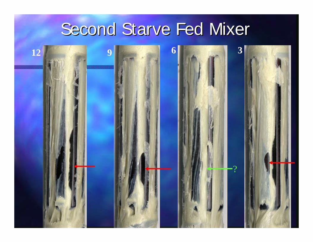
be placed far upstream. Likewise, one mixer was placed 7 L/D’s from the water cooled feed section and the screw rotated to 250 rpm. There is little chance that the material will have completed melted before the mixer. Because the inlet channel is open downstream, it does not act as a barrier to flow. Whole pellets can enter the inlet channel and begin to melt. Since hard unmelted material cannot flow over P1, whatever melt exists is believed to drain over P1, leaving the solids in the C1 channel. We believe that this acts similarly to a melt separation screw. Once the solids soften sufficiently within C1, then they can pass over P1. If the pellets do not soften sufficiently, then the pellets exit C1, and enter C2 moving upstream for additional melting opportunities or move downstream.
Figure 8 shows a cold pullout of an upstream mixer. Natural PP pellets and yellow color concentrate were fed by a starve feeder (from right). Incoming pellets are clearly visible. Unfortunately, the cold pullouts within the mixer are fragile and tend to break during removal. The empty area was originally further downstream (to the left). Figure 9 (a larger view of Figure 8) shows partially melted pellets in C1 indicated by the arrows.
Since the mixers have empty regions, the pressure is near zero. This has three advantages. First, vents may be placed over the empty regions and a vacuum will communicate with the various flows within the mixers—especially the film between P1 and P2. Second, the lower the pressure consumed by a mixer, the less heat generated. Third, the empty regions dampen surges by acting as accumulators.
Results
Previous results have described the mixer for
distributive compounding of up to 40% wood flour and
LDPE pellets; elastomer compounded with LDPE, color mixing and vinyl processing [13].
Yu et al [9] studied various PS/LDPE 95/5 blends
and achieved average domains of between 6 and 11 microns. Rauwendaal [14] studied a dry blend of high density polyethylene and polystyrene in 60:40 by weight ratio. Using an optical microscope, he found that one-third of the outer part of the extruded strand (approximately half the strand volume) was substantially coarser than the inner material and measured about 20 microns. The inner region reportedly measured about 4 microns. A somewhat similar dry blend, Figure 10, of high density and polystyrene, in a 80/20 by weight ratio, was processed using three of the mixers in a 5/8 inch, 50/1 L/D extruder. The outer boundary is negligible and the SEM shows PS domains of about 1 micron.
Ceramic particles in the 30 to 60 nanometer range
were processed using the same 3 mixer extruder above. Figures 11, 12, and 13 show SEM at 5000 X, 10,000 X and 50,000 X where it is possible to distinguish individual and slightly agglomerated particles.
In a very brief experiment (25 grams of carbon nano
tubes and 475 grams of PMMA) were processed in same extruder above but with 4 mixers and a low output screw. Figures 14, 15, and 16 show SEM at 1,000 X, 3000 X and 10,000 X where individual, apparently unentangled, carbon nano tubes are visible.
A 1 inch 36/1 extruder with up to three vents over a
similar mixer, but with forwarding pitch, proved very effective at transporting under a vent, Fig. 16, and does not recirculate flow. This is advantageous in limiting residence time for thermally sensitive materials. However, the elongational flow fields previously described and the thin film generation remain the same.
Figure 17 shows 30 mil sheet made directly from 1 MFI LDPE and wood flour. The wood was processed without drying and no additives were included to minimize degradation of the wood to demonstrate proof of concept.
Undried PMMA pellets were processed for moisture removal by looking for any sign of bubbles in the strands and with an emphasis on achieving a high output rate. Output rates were 18.4 pounds per hour with one or two vents and 17.0 with three vents. There was no vent flow at these outputs and there were no indications of moisture in the clear strands or on the surface. A vacuum of 26 inches was attached to the vents without apparent effect but as proof of concept of a vacuum application.

Figure 18, shows a 35 MI PP pellets, 2% black concentrate and 35% calcium carbonate powder were processed to make sure that entrained air could be removed and that the strand would be smooth—indicating good mixing. The mixture was processed into strands and pelletized. There were no signs of entrained air and the surface is smooth and shown at 100 times magnification, Some idea of the smoothness can be seen in the comparison at the same magnification in the “N” in a penny.
Discussion
Two broad mixing categories are polymer blends and particulate mixing. Of these, two difficult mixing areas include the immiscible polymer blends and nano particulate mixing.
The mixer is unique in its combination of properties
within single screw technology. In addition to the specific properties described, this remains a single screw extruder and retains the ability to readily generate high, stable pressures without a gear pump.
Conclusions
This mixer shows a surprising degree of mixing. Prior magnification judged the quality of mixing from 0 to about 400 times magnification. This mixer can be judged by its 3,000 to 50,000 times magnification.
Venting is often an important requirement of
extrusion compounding. This venting mechanism generates a thin film making removal of gases much more likely than in the traditional single screw methods. These initial tests are very promising.
Together with the earlier work cited, the mixer is a
flexible processing tool for many different materials. The mixer can combine multiple elongational flows, upstream axial mixing, and venting in a unique single screw extruder that is still capable of high pressure development and stable pressures. The combination adds a powerful tool for the polymer processor. To use multi-screw terminology, it is a direct compounder.
Ongoing work will be described later will include
undried PET.
Acknowledgements
To Tom Nosker and Jennifer Lynch of Rutgers for the
SEMs of the nano ceramics, PE/PS blends and most agreeable help.
References
1. C. Rauwendaal, Polymer Extrusion, Hanser
Publishers, New York, pp 386-398 (2001). 2. Ibid., pp 507-519. 3. R. Klein and I. Klein, U.S. Patent 4,290,702 (1981). 4. K. Kolossow, U. S. Patent 4,730,935 (1988) 5 C. Rauwendaal, Polymer Extrusion, Hanser
Publishers, New York, pp 463-476 (2001). 6. Ibid., p 468. 7 G. Harrah, T. Womer, “A Mixing Study of Various
Single Screw Element Using In-Line Melt Analysis,” SPE Antec (1998)
8 M. Spalding, J. A. Kuhman, D. Larson, J. Kuhman, H. Prettyman, “Performance Of A Melt-Mixing Screw With An Advanced Mixing Tip,” SPE Antec (2004)
9 D. Yu, M. Esseghir, C. Gogas, “The Use of “On-Line Optical Microscopy” for Monitoring Compounding and Other Polymer Processing,” SPE Antec (1995).
10 A. Rios, T. Osswald, “Experimental Study of Various Mixing Sections in a Single Screw Extruder,” SPE Antec (1998)
11 K. Sluzarz, M. Thompson, J. Christiano, “An Experimental Comparison of the Improved Mixing Obtained From a New Barrier Mixing Design,” SPE Antec (2001)
12 K. Luker, U.S. Patent 6,962,431 B1 (2005) 13 K. Luker, “Performance Compounding,” San
Antonio Texas (2002). 14 C. Rauwendaal, A. Rios and P. Gramann,
“Experimental Study of a New Dispersive Mixer,” SPE Antec (1999)
0P1
P2C1 C2
P = PUMPS C = CHANNEL
A
A
Figure 2: Pump and Drag Flow A - A
P1 and P2 will pump (rather than act as a barrier to pressure) when the pressure in the channels is low.
Figure 1: Union Carbide Mixer
The entrance flute dead ends at the wiping land. Pressure, generated upstream, forces material over the mixing flute where the material is sheared. The higher the pressure, the higher the heat generation.
B C3
P2 C2
P1 C1
B
Three Mixer Screw
4 L/DMixer
4 L/DMixer
3 L/DMixer
Figure 3A: Figure 3A:
C
C
CP
P
C3
C1
C2P2
P1
Mixer Flow With Input Below Pumping Capacity of P1 and P2Mixer Flow With Input Below Pumping Capacity of P1 and P2
Figure 3: Flat View Of MixerFigure 3: Flat View Of Mixer
These Arrows Show the Direction of Pressure Flow At Mixer Input
BThese Arrows Show
Direction of Drag Flow
Figure 5: Comparison Figure 5: Comparison LobalLobal MixersMixers
Bi-Lobal Kneading Disc
One Third of the Mixer
Tri-Lobal Kneading Disc
Melt flow at “lobe”and “pump” are
similarC
C
CP
P
Figure 4: Stretching Flow In Cold Figure 4: Stretching Flow In Cold Screw PulloutsScrew Pullouts
C3
C1
C2P2
P1
Enlarged View At C1 Inlet Showing Angle Of Flow Lines
C
C
CP
P
C3
C1
P2
P1
Figure Figure 6:6: Flat View Of MixerFlat View Of MixerFlood Fed InputFlood Fed Input
Entry Fill Length Increased From Figure 2
B
C2
Upstream flow eliminated by increasing the input flow.
Figure 7: Flat View of Mixer Flood Fed Input
C
C
CP
P
C3
C1
C2P2
P1
C1 C1 RecirculatoryRecirculatory Flow, Left, Greater Than C1 Entry Flow, RightFlow, Left, Greater Than C1 Entry Flow, Right
Figure 6: Flat View Of MixerFigure 6: Flat View Of MixerAt Reduced InputAt Reduced Input
Entry Fill Length Reduced From Figure 2
B
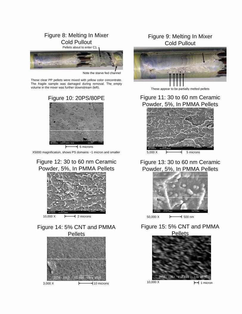
Figure 8: Melting In Mixer
Cold PulloutPellets about to enter C1.
These clear PP pellets were mixed with yellow color concentrate.The fragile sample was damaged during removal. The empty volume in the mixer was further downstream (left).
Note the starve fed channel
Figure 9: Melting In MixerCold Pullout
These appear to be partially melted pellets
Figure 11: 30 to 60 nm Ceramic Powder, 5%, In PMMA Pellets
5,000 X 5 microns
20PS/80PE20PS/80PE
Figure 10: 20PS/80PE
X5000 magnification, shows PS domains ~1 micron and smaller
5 microns
Figure 12: 30 to 60 nm Ceramic Powder, 5%, In PMMA Pellets
10,000 X 2 microns
Figure 13: 30 to 60 nm Ceramic Powder, 5%, In PMMA Pellets
50,000 X 500 nm
Figure 15: 5% CNT and PMMA Pellets
10,000 X 1 micron
Figure 14: 5% CNT and PMMA Pellets
3,000 X 10 microns
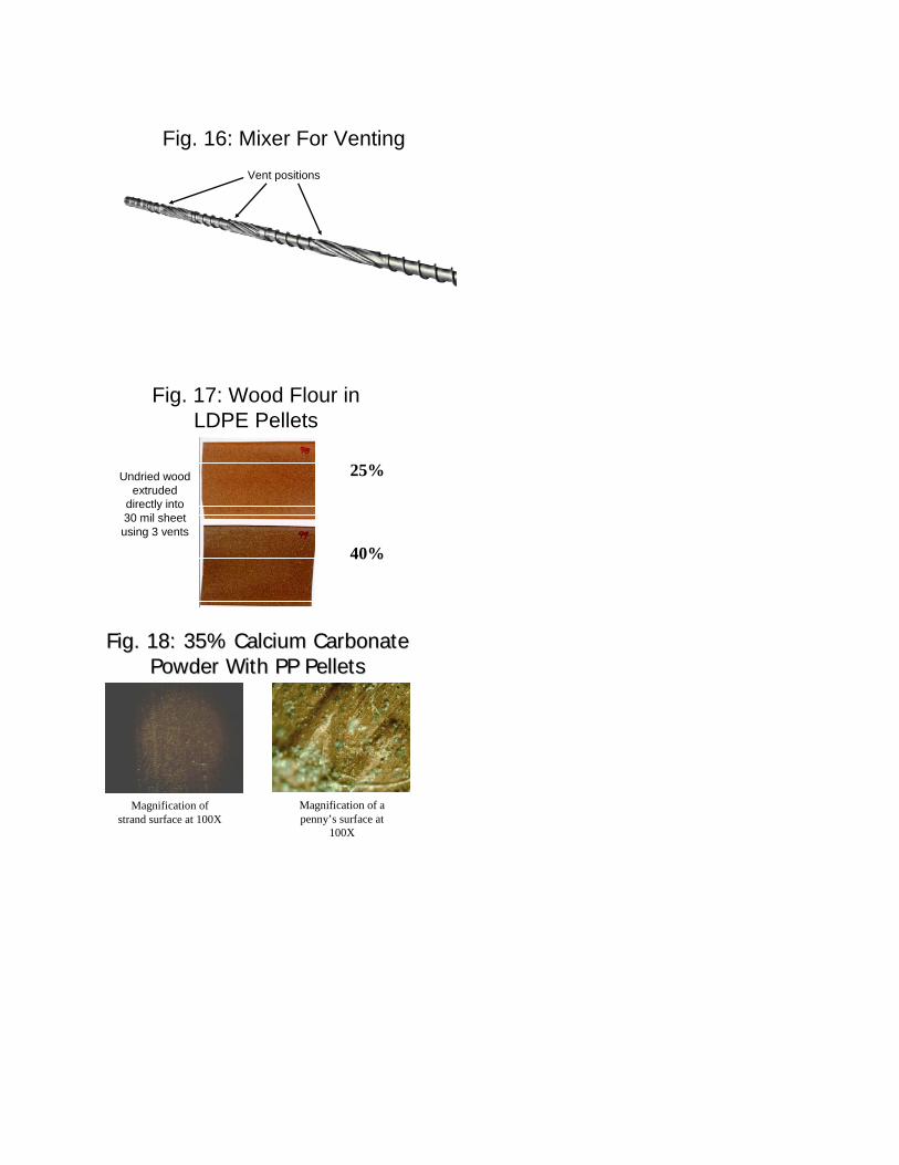
Fig. 16: Mixer For VentingVent positions
Fig. 17: Wood Flour in LDPE Pellets
25%
40%
Undried wood extruded
directly into 30 mil sheet using 3 vents
Fig. 18: 35% Calcium Carbonate Fig. 18: 35% Calcium Carbonate Powder With PP PelletsPowder With PP Pellets
Magnification of strand surface at 100X
Magnification of a penny’s surface at
100X

2007 PLACE Conference
September 16-20
St Louis, MO
Presented by: Keith LukerPresidentRandcastle Extrusion Systems Inc.
NEW THIN FILM SINGLE SCREW NEW THIN FILM SINGLE SCREW VENTING MECHANISM VENTING MECHANISM
TESTED ON TESTED ON 30% WOOD FLOUR/PELLETS30% WOOD FLOUR/PELLETS
35% CALCIUM CARBONATE/PP PELLETS 35% CALCIUM CARBONATE/PP PELLETS AND UNDRIED PMMAAND UNDRIED PMMA

How do measure extrusion mixing?How do measure extrusion mixing?

By MagnificationBy Magnification
We look at it. We look at it.

By MagnificationBy Magnification
We look at it.We look at it.We use optical microscopes. We use optical microscopes.
By MagnificationBy Magnification
We look at it.We look at it.We use optical microscopes. We use optical microscopes. We uses electron microscopes. We uses electron microscopes.

By MagnificationBy Magnification
We look at it.We look at it.We use optical microscopes. We use optical microscopes. We uses electron microscopes. We uses electron microscopes. The greater the degree of magnification The greater the degree of magnification necessary to determine mixing, the necessary to determine mixing, the better the mixture.better the mixture.

Two Common MixturesTwo Common Mixtures
Immiscible polymer blendsImmiscible polymer blendsParticulate such as color, talc, carbon Particulate such as color, talc, carbon nano tubesnano tubes

RauwendaalRauwendaal et alet al
Studied PE/PS 95/5 BlendStudied PE/PS 95/5 BlendOutside half of the rod volume was 20 Outside half of the rod volume was 20 micronsmicronsInside half of the rod was 4 micronsInside half of the rod was 4 micronsPerhaps average of ~ 12 micronsPerhaps average of ~ 12 microns
C. Rauwendaal, A. Rios and P. Gramann, “Experimental Study of a New Dispersive Mixer,” SPE Antec (1999)
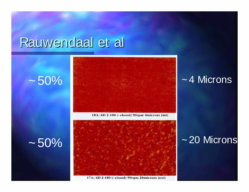
RauwendaalRauwendaal et alet al
~50%
~50%
~4 Microns
~20 Microns

Yu et alYu et al
PSPS--95/LDPE95/LDPE--5 Blend 5 Blend Average Domains 6 to 11 micron rangeAverage Domains 6 to 11 micron range
D. Yu, M. Esseghir, C. Gogas, “The Use of “On-Line Optical Microscopy” for Monitoring Compounding and Other Polymer Processing,” SPE Antec (1995).

Particulate MixingParticulate Mixing
ColorColor
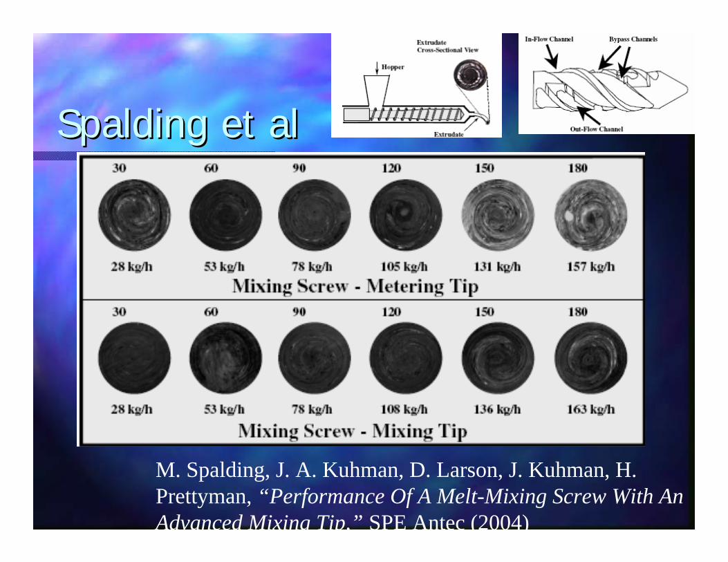
Spalding et alSpalding et al
M. Spalding, J. A. Kuhman, D. Larson, J. Kuhman, H. Prettyman, “Performance Of A Melt-Mixing Screw With An Advanced Mixing Tip,” SPE Antec (2004)
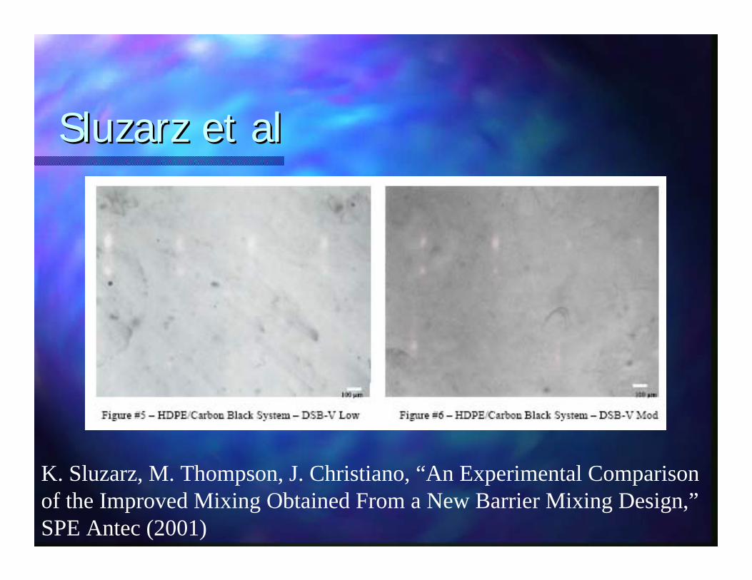
SluzarzSluzarz et alet al
K. Sluzarz, M. Thompson, J. Christiano, “An Experimental Comparison of the Improved Mixing Obtained From a New Barrier Mixing Design,”SPE Antec (2001)

SluzarzSluzarz et alet al
K. Sluzarz, M. Thompson, J. Christiano, “An Experimental Comparison of the Improved Mixing Obtained From a New Barrier Mixing Design,”SPE Antec (2001)
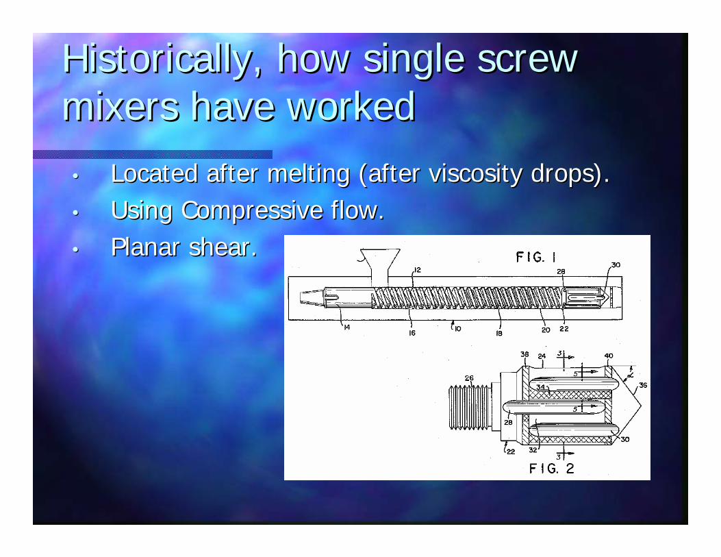
Historically, how single screw Historically, how single screw mixers have workedmixers have worked
•• Located after melting (after viscosity drops). Located after melting (after viscosity drops). •• Using Compressive flow.Using Compressive flow.•• Planar shear.Planar shear.

Union Carbide MixerUnion Carbide Mixer((akaaka MaddocksMaddocks Mixer)Mixer)

HPMHPM’’ss Double Wave MixerDouble Wave Mixer

CRD MixerCRD Mixer
C. Rauwendaal, A. Rios and P. Gramann, “Experimental Study of a New Dispersive Mixer,” SPE Antec (1999)
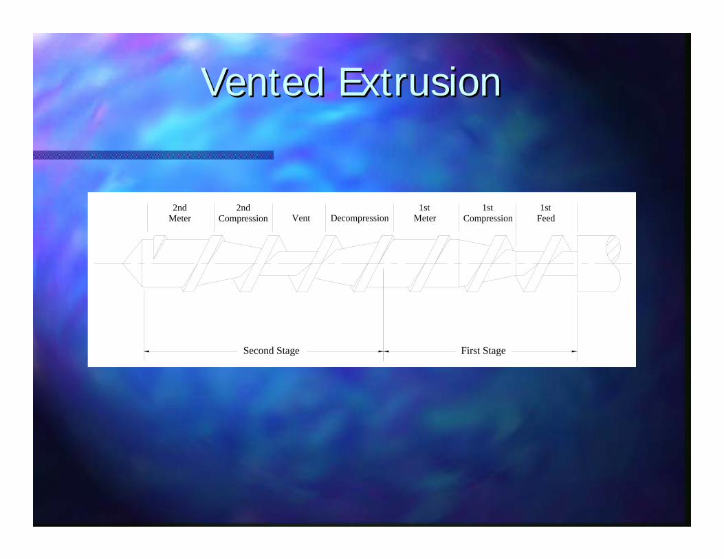
2ndMeter Vent
1stMeter
1stCompression
1stFeed
First StageSecond Stage
Decompression2nd
Compression
Vented ExtrusionVented Extrusion

Imagine A Screw Imagine A Screw Without A Flight At The EndWithout A Flight At The End

In The Smooth Section,In The Smooth Section,What Path Will A Particle Take? What Path Will A Particle Take?

A Spiral A Spiral
Pressure Flow
Drag Flow
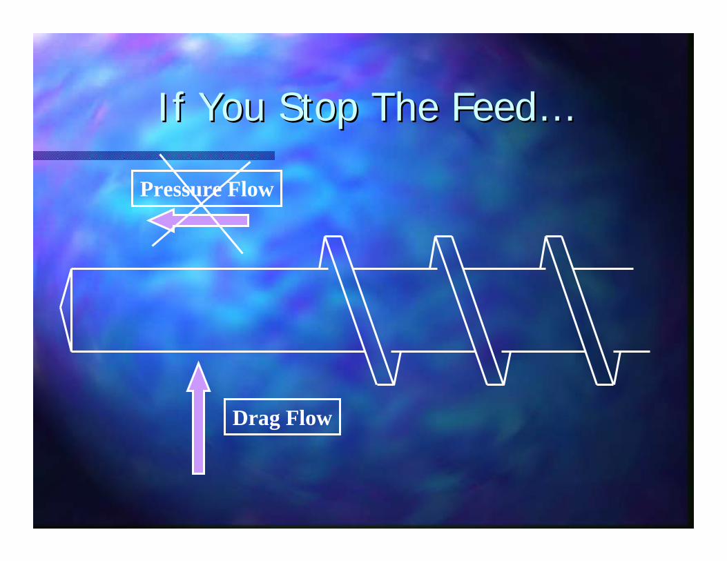
If You Stop The FeedIf You Stop The Feed……
Drag Flow
Pressure Flow

Material Is Pumped In A CircleMaterial Is Pumped In A Circle
Drag Flow
Pressure Flow
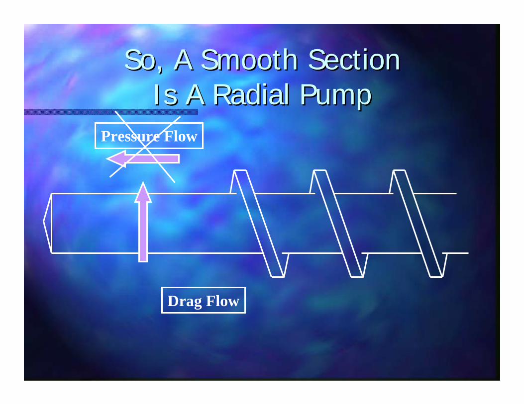
So, A Smooth SectionSo, A Smooth SectionIs A Radial PumpIs A Radial Pump
Drag Flow
Pressure Flow

End View Of Radial PumpEnd View Of Radial Pump’’ssParticle PathParticle Path
Drag Flow
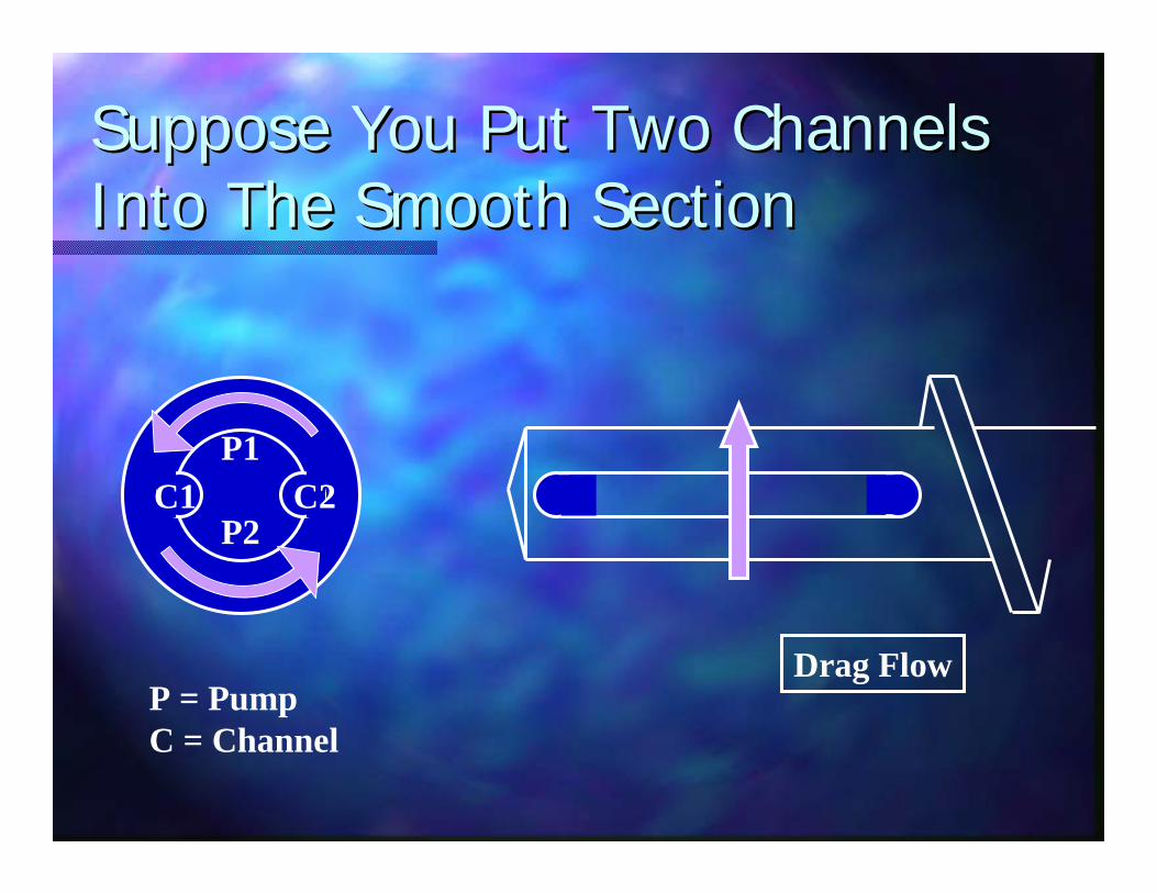
Suppose You Put Two Channels Suppose You Put Two Channels Into The Smooth SectionInto The Smooth Section
0
Drag Flow
P1
P2C1 C2
P = PumpC = Channel
C3
C1
C2P2
P1
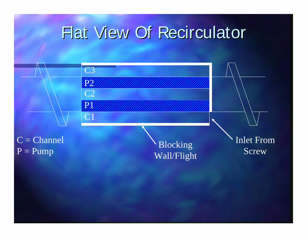
Flat View Of RecirculatorFlat View Of Recirculator
C = ChannelP = Pump
Inlet FromScrew
BlockingWall/Flight

C
C
CP
P
Pressure Flow At Inlet ChannelPressure Flow At Inlet Channel
Suppose the pump did not pump. Then channel flow would resemble the typical bullet shaped flow, faster at the center, slower at boundaries.
C3
C1
C2P2
P1
Pressure Flow
C
C
CP
P
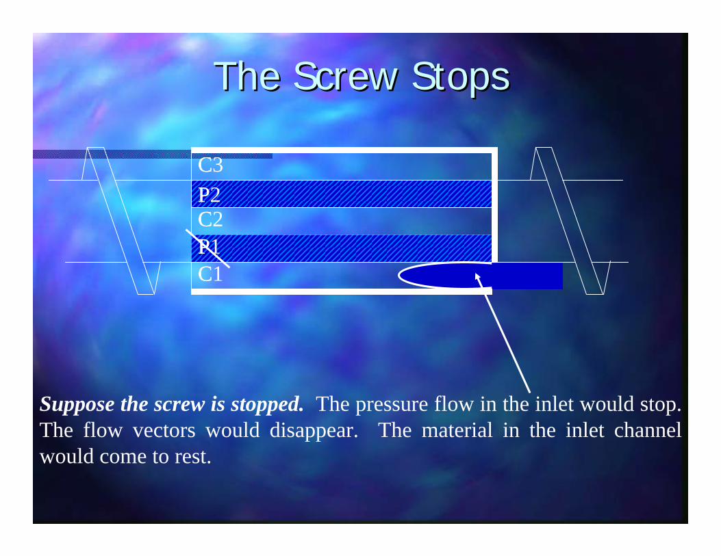
The Screw StopsThe Screw Stops
Suppose the screw is stopped. The pressure flow in the inlet would stop. The flow vectors would disappear. The material in the inlet channel would come to rest.
C3
C1
C2P2
P1

C
C
CP
P
Imagine that the mixer (not the screw) were rotated. The pump, P1, would drag the material in a vector perpendicular to the screw axis until the polymer loses contact with the barrel depending on the “melt strength” of the polymer.
Drag Flow At PumpDrag Flow At Pump
C3
C1
C2P2
P1
Drag Flow

C
C
CP
P
When the mixer rotates with the screw, the vectors combine. The pump still drags the material in a vector perpendicular to pressure flow. And, pressure flow pushes material down the inlet channel. The rate of pressure flow is set to equal the drag flow. The volume of material in the inlet channel reaches equilibrium and does not fill further.
Combined Vectors Induce Combined Vectors Induce Elongational FlowElongational Flow
This line shows the combined vector of pressure and drag flow.
C3
C1
C2P2
P1
C
C
CP
P
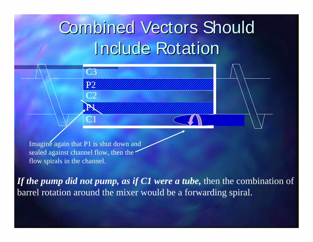
If the pump did not pump, as if C1 were a tube, then the combination of barrel rotation around the mixer would be a forwarding spiral.
Combined Vectors Should Combined Vectors Should Include RotationInclude Rotation
C3
C1
C2P2
P1
Imagine again that P1 is shut down and sealed against channel flow, then the flow spirals in the channel.

C
C
CP
P
Combined Vectors Stretch The Combined Vectors Stretch The Surface Area Of Spiral FlowSurface Area Of Spiral Flow
C3
C1
C2P2
P1
When the P1 is started, during such flow, channel elongation takes place and the spiral surface area increases. This continues through the fine elongation in the approach to the pump.

C
C
CP
P
Stretching Flow Confirmed Stretching Flow Confirmed By Cold Screw PulloutsBy Cold Screw Pullouts
C3
C1
C2P2
P1
Flow Lines
C
C
CP
P
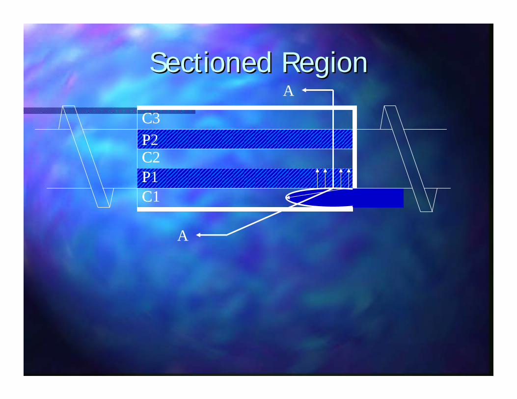
Sectioned RegionSectioned RegionA
A
C3
C1
C2P2
P1

First Channel/First PumpFirst Channel/First Pump
P = PumpP = PumpC = ChannelC = Channel
C1C2
C3
P2
P1

Fine ElongationFine ElongationRegion Of
Fine Elongation
As the material is drawn into the approach of the first pump, it experiences fine elongation at low pressure:
•Low pressure means the lowest possible heat rise•Maximum elongation. Imagine, for example, a bubble.
C1P2
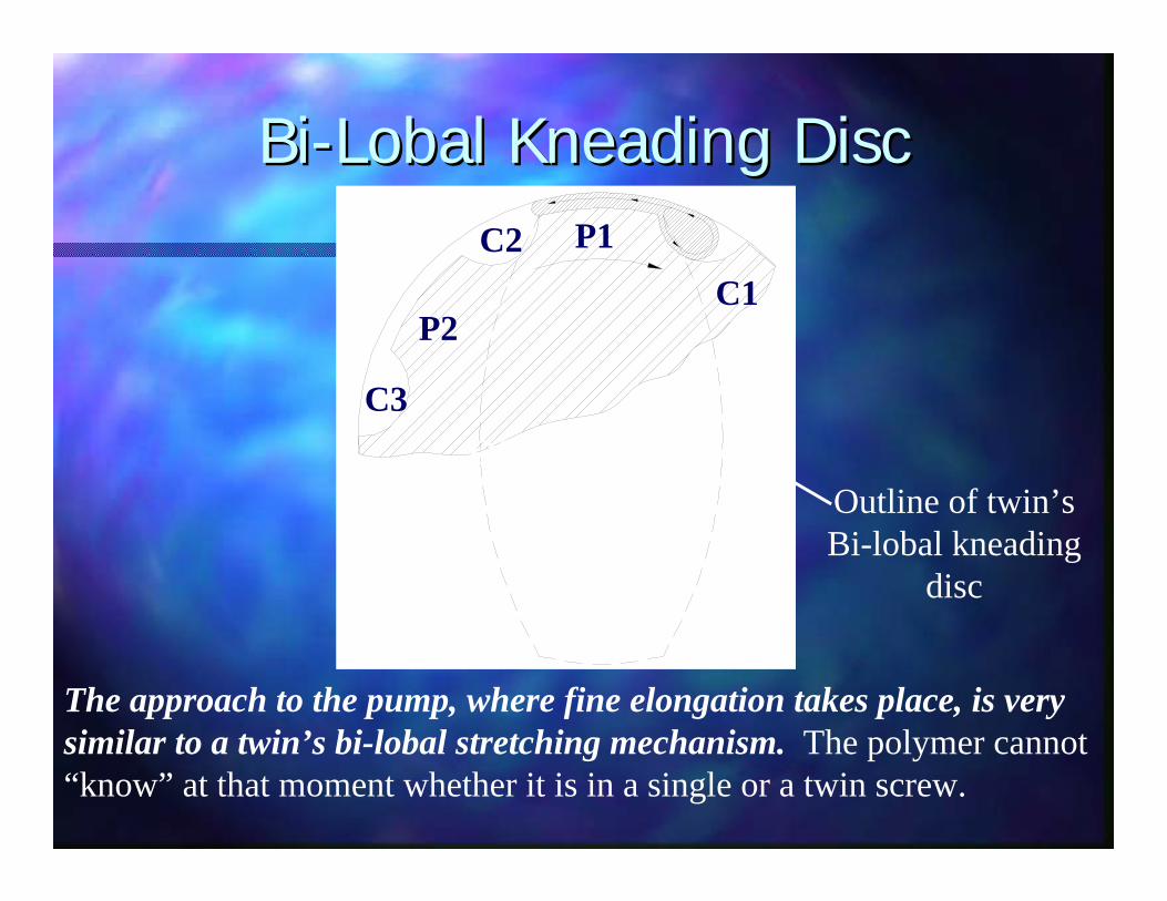
BiBi--Lobal Kneading DiscLobal Kneading Disc
The approach to the pump, where fine elongation takes place, is very similar to a twin’s bi-lobal stretching mechanism. The polymer cannot “know” at that moment whether it is in a single or a twin screw.
Outline of twin’sBi-lobal kneading
disc
C1P1
P2
C2
C3Q092205.WLG

TriTri--LobalLobal Kneading DiscKneading Disc
Tri-Lobal kneading discs divide the flow into 3 smaller masses for better mixing—just as in the Recirculator.

Thin Film Region & DischargeThin Film Region & Discharge
Thin film exposed to second and vacuum.
DischargeChannel (C3)
C1C2
C3
P1
P2
C
C
CP
P
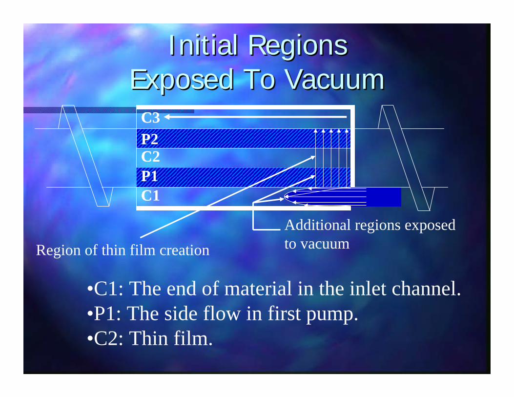
•C1: The end of material in the inlet channel. •P1: The side flow in first pump. •C2: Thin film.
Initial Regions Initial Regions Exposed To VacuumExposed To Vacuum
Region of thin film creationAdditional regions exposedto vacuum
C3
C1
C2P2
P1

C
C
CP
P
Discharge ChannelDischarge Channel
C3
C1
C2P2
P1
C
C
CP
P
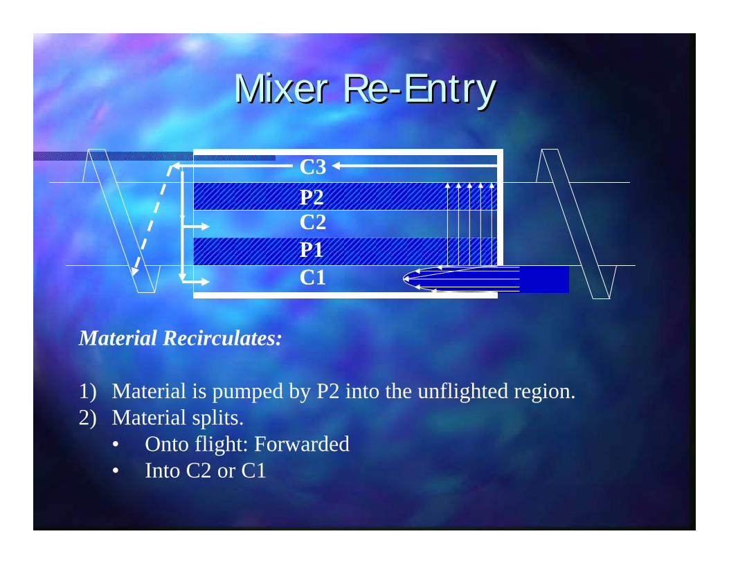
Material Recirculates:
1) Material is pumped by P2 into the unflighted region. 2) Material splits.
• Onto flight: Forwarded• Into C2 or C1
Mixer ReMixer Re--EntryEntry
C3
C1
C2P2
P1
C
C
CP
P
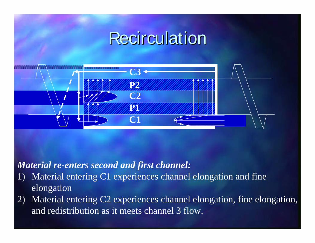
Material re-enters second and first channel: 1) Material entering C1 experiences channel elongation and fine
elongation2) Material entering C2 experiences channel elongation, fine elongation,
and redistribution as it meets channel 3 flow.
RecirculationRecirculation
C3
C1
C2P2
P1
C
C
CP2
P
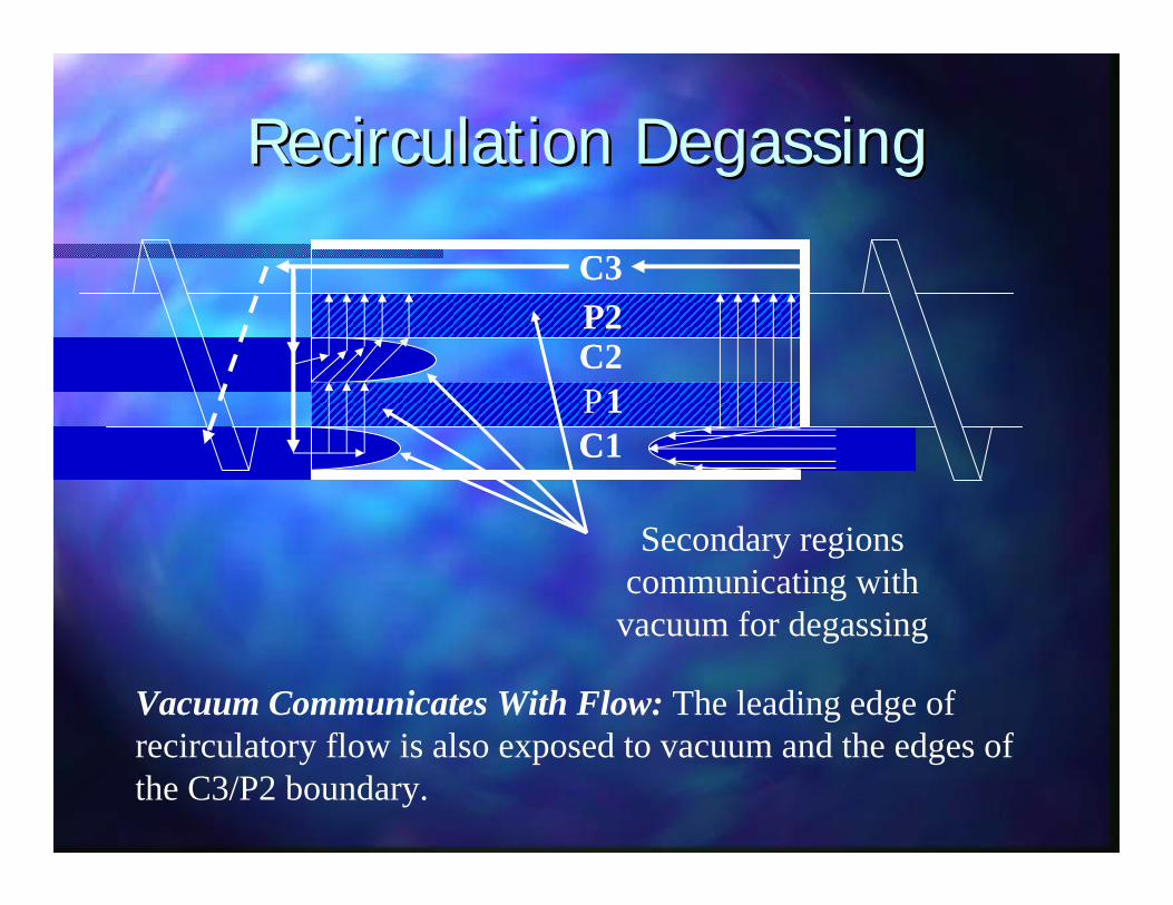
Vacuum Communicates With Flow: The leading edge of recirculatory flow is also exposed to vacuum and the edges of the C3/P2 boundary.
Recirculation DegassingRecirculation Degassing
Secondary regions communicating with
vacuum for degassing
C3
C1
C21

PumpingLand
Inlet
Discharge
BT MixerHow Each Mixer WorksHow Each Mixer Works
Empty Portion Of Channel
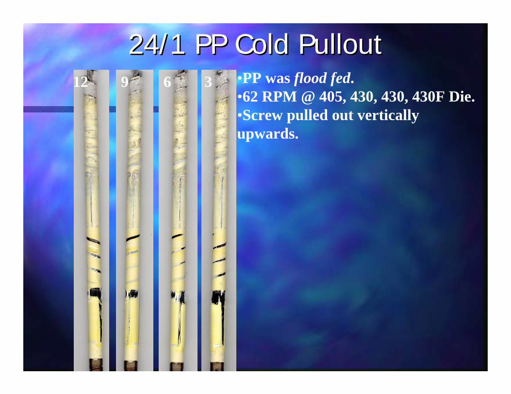
69 •PP was flood fed.•62 RPM @ 405, 430, 430, 430F Die.•Screw pulled out vertically upwards.
24/1 PP Cold Pullout24/1 PP Cold Pullout12 36

12 9 6 3
PP Cold PulloutsPP Cold Pullouts
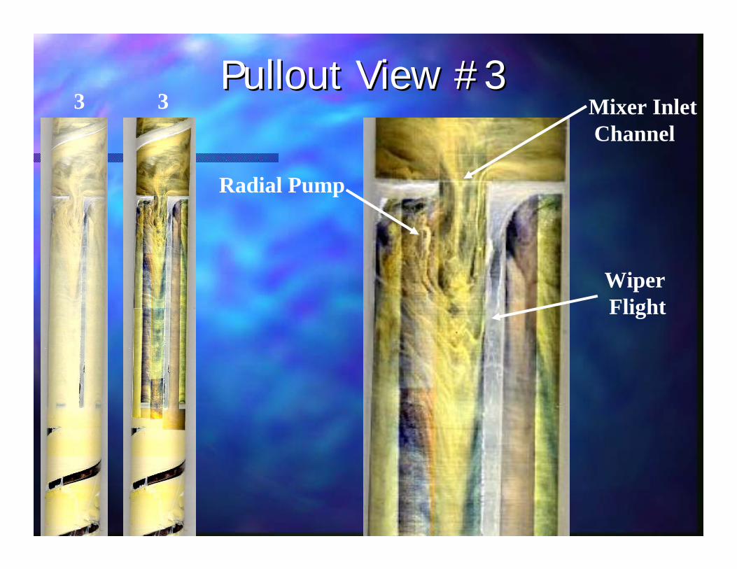
3 3Pullout View #3Pullout View #3
Mixer InletChannel
Radial Pump
Wiper Flight
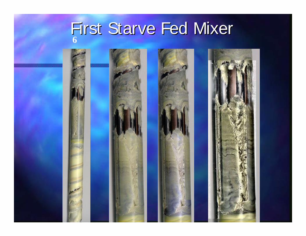
6First Starve Fed MixerFirst Starve Fed Mixer
912 36
Second Starve Fed MixerSecond Starve Fed Mixer
?

Previously Reported ResultsPreviously Reported Results
Melt Blends, measured by eye. Melt Blends, measured by eye.

UC Mixer Double Wave The Mixer
10 mil cast film:10 mil cast film:••10% 10% elastomerelastomer pellets & LDPE pelletspellets & LDPE pellets••Same temperature and output.Same temperature and output.
Dispersion Above Critical Shear StressDispersion Above Critical Shear Stress
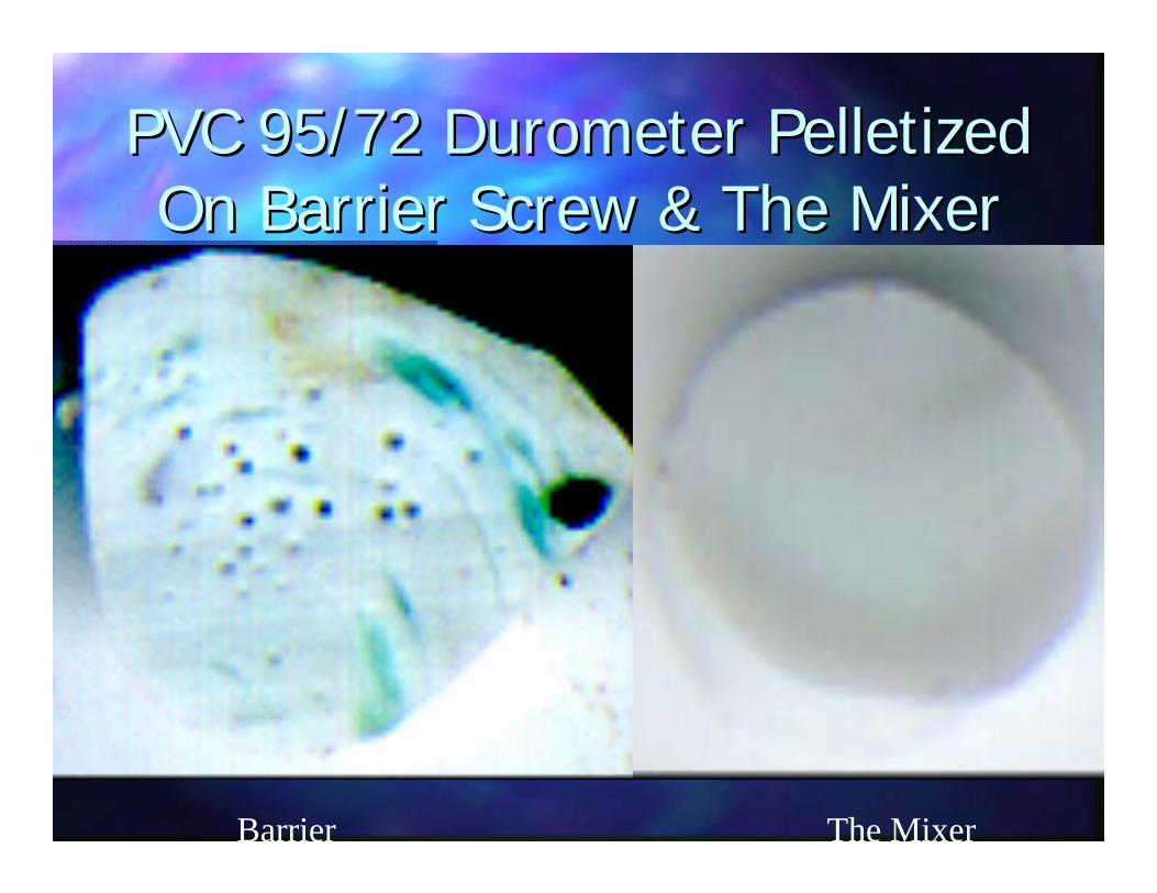
PVC 95/72 PVC 95/72 DurometerDurometer PelletizedPelletizedOn Barrier Screw & The MixerOn Barrier Screw & The Mixer
Barrier The Mixer

PVC 95/72 PVC 95/72 DurometerDurometer PelletizedPelletizedOn Barrier Screw & The MixerOn Barrier Screw & The Mixer
FromMixer
FromBarrier

20PS/80PE at 5,000X20PS/80PE at 5,000X

Previously Reported ResultsPreviously Reported Results
Color, measured by eye. Color, measured by eye.

UC Mixer The Mixer
Flexible PVC pellets/0.5% red/0.5% yellow concentrate
Coloring Vinyl FilmColoring Vinyl Film
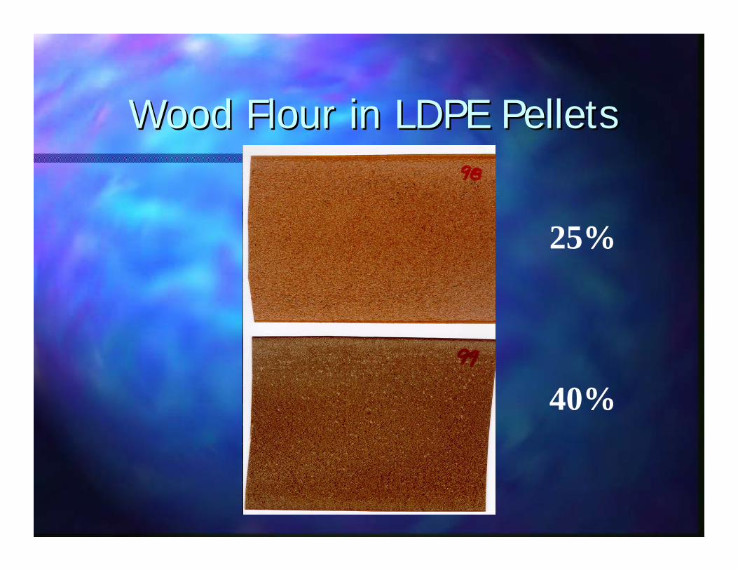
Wood Flour in LDPE PelletsWood Flour in LDPE Pellets
25%
40%
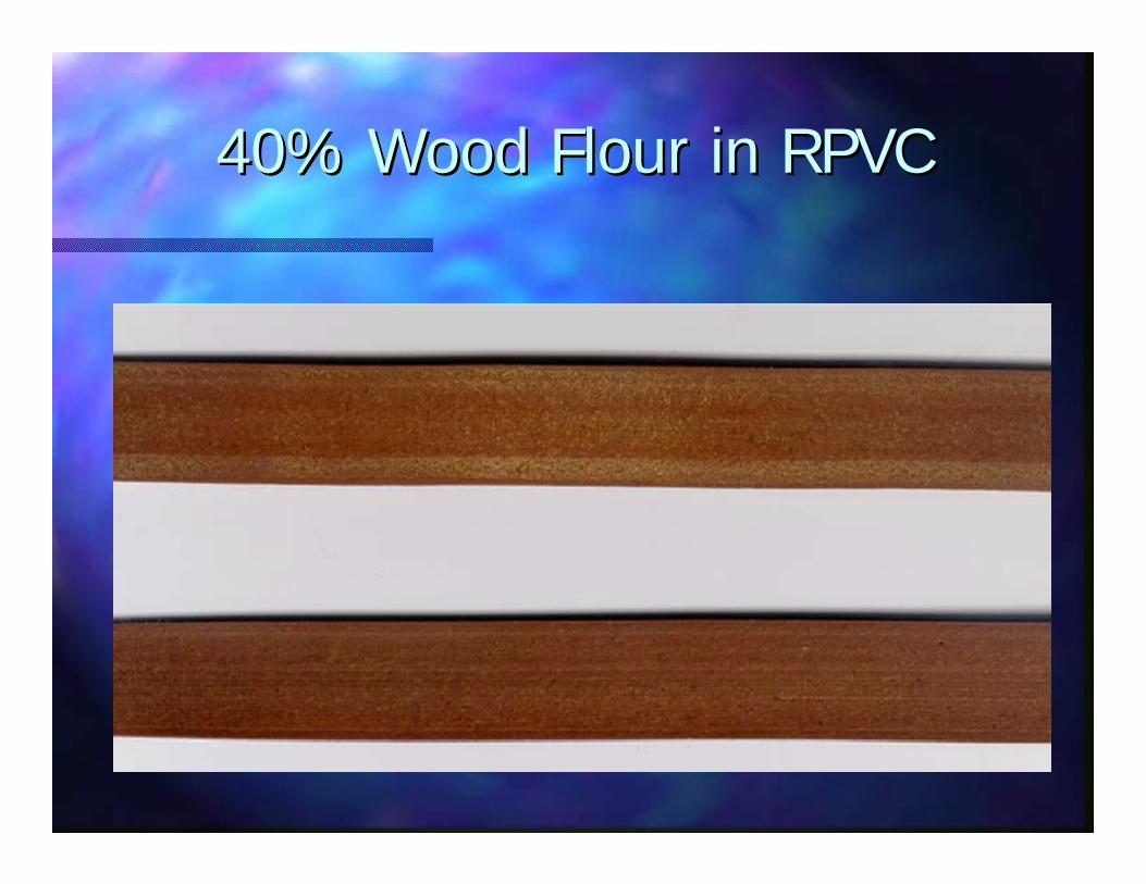
40% Wood Flour in RPVC40% Wood Flour in RPVC

Mixing NanoMixing Nano--Particles And PelletsParticles And Pellets
5% Ceramic 5% Ceramic NanoparticlesNanoparticles
Average Size: Average Size: 45nm Diameter45nm Diameter
++

Why Is This Difficult?Why Is This Difficult?
++
The worse the input mixture is, the more difficult The worse the input mixture is, the more difficult the mixing problem.the mixing problem.
5% Ceramic 5% Ceramic NanoparticlesNanoparticles
Average Size: Average Size: 45nm Diameter45nm Diameter

Just How Big is a 30 to 60 Just How Big is a 30 to 60 Nanometer Particle Anyway?Nanometer Particle Anyway?

A Pellet Is 70,000 Times Bigger A Pellet Is 70,000 Times Bigger Than A 45nm ParticleThan A 45nm Particle

Imagine That A 45 Nanometer Sphere Imagine That A 45 Nanometer Sphere Was The Size Of A BaseballWas The Size Of A Baseball
If a 45 nanometer particle = If a 45 nanometer particle =
Then, how high would a 1/8 inch pellet be?Then, how high would a 1/8 inch pellet be?
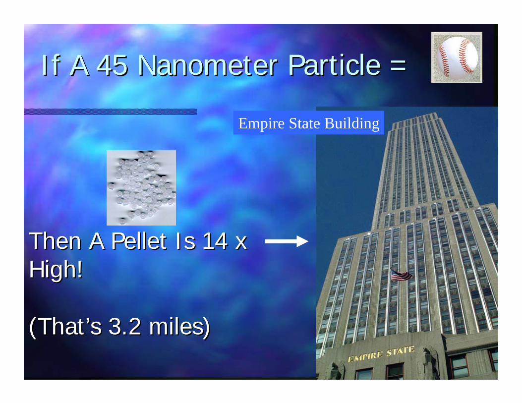
If A 45 Nanometer Particle = If A 45 Nanometer Particle =
Then A Pellet Is 14 xThen A Pellet Is 14 xHigh! High!
(That(That’’s 3.2 miles)s 3.2 miles)
Empire State Building

Ceramic NanoCeramic Nano--CompositesCompositesAcrylic Pellets & 5% Nano PowderAcrylic Pellets & 5% Nano Powder
In 30 to 60 nm RangeIn 30 to 60 nm Range

Ceramic NanoCeramic Nano--CompositesCompositesAcrylic Pellets & 5% Nano PowderAcrylic Pellets & 5% Nano Powder
In 30 to 60 nm RangeIn 30 to 60 nm Range

Ceramic NanoCeramic Nano--CompositesCompositesAcrylic Pellets & 5% Nano PowderAcrylic Pellets & 5% Nano Powder
In 30 to 60 nm RangeIn 30 to 60 nm Range

Contamination This picture shows untangled CNT’s
This sample of 600 grams was processed in Randcastle’s 50/1, low output, 4 Recirculator screw, 350 rpm, 5/8 inch Microtruder. Wereturned 300 grams to the customer in pelletized form.
Not only is the mixing quality outstanding, but we are told that even though the customer has twin screw extruders, they have not beenable to produce the dis-entangled CNT’s in the picture on the right.
5% Carbon Nano5% Carbon Nano--Tubes In PMMATubes In PMMA

2% Carbon Nano2% Carbon Nano--Tubes & PCTubes & PC
100,000 X

Mixer For VentingMixer For Venting
Vent positions

Undried PMMAUndried PMMA
11””, 36/1 L/D, 36/1 L/DTwo Vents, Atmospheric Two Vents, Atmospheric 18.4 PPH18.4 PPH
Undried PMMAUndried PMMA
11””, 36/1 L/D, 36/1 L/DTwo Vents, Atmospheric Two Vents, Atmospheric 18.4 PPH18.4 PPHThree Vents, AtmosphericThree Vents, Atmospheric17.0 PPH17.0 PPH

Wood Flour in Wood Flour in LDPE PelletsLDPE Pellets
25%
40%
Undried wood
extruded directly into 30 mil sheet using 3 vents

35% Calcium Carbonate Powder 35% Calcium Carbonate Powder With PP PelletsWith PP Pellets
Magnification of strand surface at
100X
Magnification of a penny’s
surface at 100X

Mixer/Vent Summary Mixer/Vent Summary
Multiple Elongational Flow FieldsMultiple Elongational Flow FieldsComplete Complete loballobal capturecaptureTriTri--LobalLobal division of the meltdivision of the meltUpstream axial mixing Upstream axial mixing Can be flood or starve fedCan be flood or starve fedVenting mechanism is novel and effective Venting mechanism is novel and effective
The Mixer/Venting Element:The Mixer/Venting Element:
Mixer/Vent Summary Mixer/Vent Summary
Mixing at much higher degrees of Mixing at much higher degrees of magnification for both magnification for both immisibleimmisible blends blends and particulate.and particulate.A unique degassing methodA unique degassing methodHigh Filler compoundingHigh Filler compoundingThermally sensitive material processingThermally sensitive material processing

Generating high pressuresGenerating high pressuresStable pressuresStable pressuresSingle heat historySingle heat historyLow CostLow CostUses alternating elongational/shear flowsUses alternating elongational/shear flows
The Mixer/Vents retains the advantages of single The Mixer/Vents retains the advantages of single screws: screws:
Mixer/Vent Summary Mixer/Vent Summary
Thanks To:Thanks To:
Tom Tom NoskerNosker and Jennifer Lynch of and Jennifer Lynch of Rutgers for the pictures of the PS/PE Rutgers for the pictures of the PS/PE blends on the Mixer and the ceramic blends on the Mixer and the ceramic nano particlesnano particles
Advanced Materials via Immiscible Polymer ProcessingA Cooperative Center for Research, Development and CommercializationRUTGERS
THE STATE UNIVERSITY OF NEW JERSEY

Thank YouThank YouPRESENTED BY
Keith LukerPresident
Randcastle Extrusion Systems, [email protected]
Please remember to turn in your evaluation sheet...