Embed Size (px)
Citation preview

>
New Technology for Trace Contaminant, Acid Gas Removal and Sulfur Recovery from Coal Gasification Syngas
Dennis Leppin, P.E., Gas Technology Institute,Des Plaines, Illinois, USA, PresentorRaj Palla, Shain Doong, Rachid Slimane, Howard Meyer,GTIScott Lynn, UC-Berkeley, Contributors
Presented at GTC 2005San Francisco, CAOctober 12, 2005

2
Disclaimer> The work reported in what follows represents research from
numerous GTI researchers and subject matter experts and each of the 5 projects discussed can easily be a 20 min talk, so my apologies in advance for any oversimplifications and omissions and general lack of presentation of “data”
> More detailed presentations are available on most of these topics
> Contact me if interested
> Other relevant work is also underway at GTI which was omitted to make for a manageable presentation

3
Introduction
> Syngas cleanup is complicated and expensive, but necessary
> Possibility of advancing the gasifier technology significantly may be moderate at this point
> GTI is working this issue on several fronts which will be briefly discussed in what follows

4
Key Issues in Syngas Cleanup
> Trace contaminant removal> Hot Gas Cleanup> CO Shift and COS Hydrolysis> Bulk S removal> High CO2 to H2S acid gas treating
(selective removal requirement)> Low tonnage (<15-20 TPD) S recovery
where Claus is not feasible

5
GTI Technology Developments
> UCSRP-HP Multi-Contaminant Removal> Morphysorb® Process> “Direct Oxidation” S and Hg
Removal/Recovery> “Ultra-Clean” Process> H2 Membrane Development

6
Multi-Contaminant Removal Process (UCSRP-HP)

7
UCSRP-HP Background
> Developed over a number of years by Scott Lynn, Prof. Emeritus at Univ. of CA, Berkeley. Regents issued lic. option to a private individual, who in turn licensed GTI
> GTI has conducted technoeconomicstudies for natural gas (in which applications a 40%benefit was estimated), bench-scale tests, and recently, tests with syngas
> DOE, ICCI and GTI now funding scale-up developments at GTI

8
UCSRP – HP Basic Concept> Patented concept
> Solvent with high temperature stability and high SO2 and H2S solubility – DGM and related compounds
> Homogenous catalyst for Claus Reaction operates above sulfur melting point
> S combustion to produce SO2 which is then absorbed in solvent and cycled to absorber –remainder of S removed as product
> DEG loop to remove other contaminants
> Syngas delivered at well above S melting point by cross exchanger

9
UCSRP-HP Applications:Treatment of Coal-Derived Syngas

10
Research at GTI – High Pressure Lab Reactor

11
UCSRP Lab Results
> Reactions occur with high rates> Solvent is stable (40 day test)> No unexpected corrosion results> Bright sulfur product> For syngas application – COS Hydrolysis
occurs at reactor conditions

12
UCSRP Status
> DOE and ICCI funding further development at GTI
> GTI tests will include measurement of kinetics and mass transfer and contactor/separation issues and add’l. physical props measurements as well as IGCC reference case (with assistance of ConocoPhillips)

13
Morphysorb

14
Project Background> Originally started in 1972 to treat coal gasifier
effluents under A.G.A contract (1972-77)> Screened 108 solvents> Selected NFM as the best candidate> Project restarted in 1990 under GRI sponsorship and
later joined by USDOE> Uhde joined GTI team in 1996> Laboratory, pilot plant and scale-up studies
completed> Patented for natural and syngas treating in various
regions> The process is now commercially available as
Morphysorb exclusively through Uhde

15
Morphysorb Process> What is it?
– Proprietary solvent/process(GTI and Uhde owns the technology)
– N- formyl morpholine/N-acetyl morpholine mixtures
> What is the application?– Bulk or trace removal of acid gas components – Subquality natural gas upgrading to either pipeline or LNG specification– Selective removal of H2S from natural/synthesis gas for generation of acid gas
stream suitable for Claus plant feed – Selective removal of H2S, CO2, COS, CS2, mercaptans and other components
from coal/oil gasification syngas at IGCC facilities
> Advantages– Higher solvent loading = lower circulation or higher throughput– Lower co-absorption of hydrocarbons (less losses)– Low corrosion, low environmental hazard– Low foaming potential– Low capital and operating costs

16
Morphysorb Pilot Plant Test UnitPilot Plant Specifications– Pressure, 1200 psig
– Circulation Rate,35 gpm max.
– Feed Gas Flow Rates Up to 1.2 MMSCF/d
– Overall Dimensions,12 x 12 x 60 ft.
– To be relocated to FlexFuel in 2005

17
Planned Mods to Flex-Fuel Facility

18
Duke Energy’s Kwoen PlantWorld’s Largest AGI Facility

19
Filter/Separator
Recycle Flash Drums
Absorbers 1st Stage Acid GasCompression
2nd to 4th StageAcid GasCompression
1st StageRecycle GasCompression
2nd StageRecycleGas Compression
Acid GasInjectionWell
Upgraded Sour Gas
Lean Morphysorb Acid Gas Flash Drums
Acid Gas
Kwoen Plant Process Flow Diagram
20
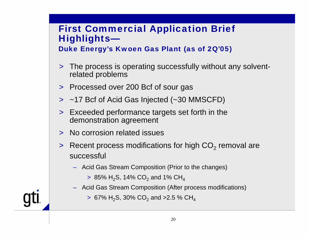
First Commercial Application Brief Highlights—Duke Energy’s Kwoen Gas Plant (as of 2Q’05)
> The process is operating successfully without any solvent-related problems
> Processed over 200 Bcf of sour gas> ~17 Bcf of Acid Gas Injected (~30 MMSCFD)> Exceeded performance targets set forth in the
demonstration agreement> No corrosion related issues> Recent process modifications for high CO2 removal are
successful– Acid Gas Stream Composition (Prior to the changes)
> 85% H2S, 14% CO2 and 1% CH4
– Acid Gas Stream Composition (After process modifications)> 67% H2S, 30% CO2 and >2.5 % CH4
21
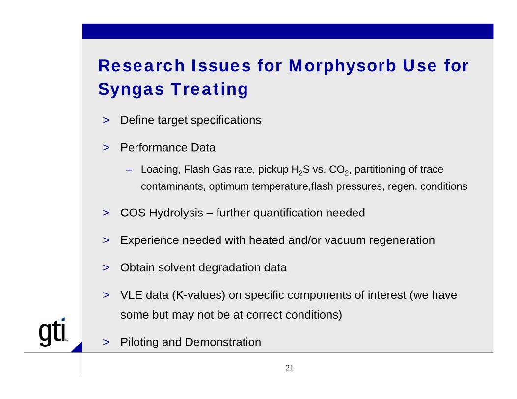
Research Issues for Morphysorb Use for Syngas Treating> Define target specifications
> Performance Data
– Loading, Flash Gas rate, pickup H2S vs. CO2, partitioning of trace contaminants, optimum temperature,flash pressures, regen. conditions
> COS Hydrolysis – further quantification needed
> Experience needed with heated and/or vacuum regeneration
> Obtain solvent degradation data
> VLE data (K-values) on specific components of interest (we have
some but may not be at correct conditions)
> Piloting and Demonstration

22
Morphysorb Summary> Commercial for Bulk Acid Gas Removal
– Several add’l. world-scale plants in various licensing stages
> Can be configured for various treating services, e.g., pure CO2 capture, LNG feed specs (50 ppmv CO2), natural gas treating (4 ppmv H2S) and syngas cleanup
> May have advantageous properties for syngas treating? Higher capacity?, COS hydrolysis, lower H2 absorption, lower eq’d. circ. Rates
> Further testing for syngas is warranted – not currently funded but some in-house research being carried out by Uhde GmbH and GTI.

23
Direct Oxidation of H2S

24
“DO” Concept
AIR
SYNGAS w/H2S
SULFUR
Direct Oxidation Reactor
Sulfur Condenser
DESULFURIZEDSYNGAS
AIR
SYNGAS w/H2S
SULFUR
Direct Oxidation Reactor
Sulfur Condenser
DESULFURIZEDSYNGAS
H2S + O2 S + H2O•Limits to amount of H2S that can be processed in a single-stage•Equilibrium conversion limits•Hg may be removed concomitantly along with elemental S•Various “Back-End” processes may be envisioned•Offerred Commercially by M-I SulfaTreat for Natural Gas cleanup

25
CTU for High Pressure Operation
> CTU is rated for 800 psig operation
> Simulated gas blended via seven mass flow controllers
> CTU can be operated up to 700 ºF
> Equipped with State-of-the-art Analytical Systems
> Ambient Personal Monitors– H2S, SO2,LEL and CO

26
CTU Simplified PFD
27
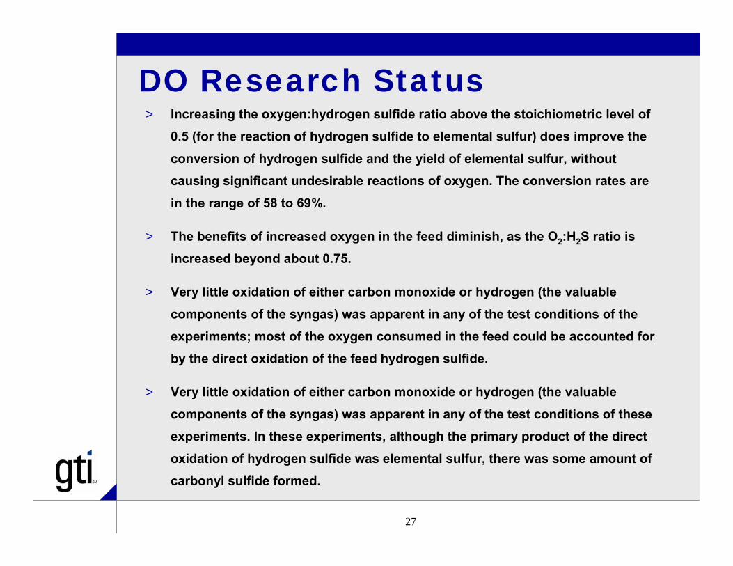
DO Research Status> Increasing the oxygen:hydrogen sulfide ratio above the stoichiometric level of
0.5 (for the reaction of hydrogen sulfide to elemental sulfur) does improve the conversion of hydrogen sulfide and the yield of elemental sulfur, without causing significant undesirable reactions of oxygen. The conversion rates are in the range of 58 to 69%.
> The benefits of increased oxygen in the feed diminish, as the O2:H2S ratio is increased beyond about 0.75.
> Very little oxidation of either carbon monoxide or hydrogen (the valuable components of the syngas) was apparent in any of the test conditions of the experiments; most of the oxygen consumed in the feed could be accounted for by the direct oxidation of the feed hydrogen sulfide.
> Very little oxidation of either carbon monoxide or hydrogen (the valuable components of the syngas) was apparent in any of the test conditions of these experiments. In these experiments, although the primary product of the direct oxidation of hydrogen sulfide was elemental sulfur, there was some amount of carbonyl sulfide formed.
28
Ultra-Clean Process

29
Sorbent Fines
Ultra-Clean Syngas
SyngasCooler
Sulfur & Halide Bulk Removal
System
SorbentsMakeup and
Disposal
SorbentFines
Injection
SorbentFines
Injection
RawSyngas
Sorbent Fines& Char
RecoveredSulfur Stage I
Filter -ReactorStage II
Filter -ReactorGasifier
Cyclone
RawFuel Gas
Bedchar/sorbent
Cyclonechar/sorbent
Steam
Oxidant
Coal, Biomass, OtherCarbonaceous Fuels
Limestonesorbent
Novel Gas Cleaning Process Concept: Use an existing particulate control device (barrier filter) as a chemical reactor for multi-pollutant control at hot/warm temperatures

30
PCD’s as Barrier Filter-ReactorsBarrier filters applied as semi-continuous
packed-bed reactors for simultaneous control of particulates and gaseous contaminants
Dry ProcessAvoids fuel gas condensation
Coupling efficient particle capture with an effective entrained/filter cake reaction environment
Multiple contaminants can be simultaneously controlled in a single filter-reactor vessel (S, halide, and Hg compounds)
Potential to incorporate capability to control other contaminants (ammonia, trace metals (As, Se, Cd))
Process uses powdered sorbent particles with very high specific surface area
No need for highly porous support structureNo need for special particle attrition
resistance
Low-cost

31
Pilot Test Facility Configuration
Direct Spray Quench Trona Sorbent
Feeder
Conditioning Filter-Reactor (Stage I)
CF-R Let-down Hopper
Stage II de-Cl Sorbent FeederStage II de-S
Sorbent Feeder
Test Filter-Reactor (Stage II)
Sulfur Guard Bed
SGB Pre-heater
Trim Cooler By-pass & UCP Pressure Control Systems

32
Sorbent Injection Systems
Pressurized ShellLoading
Nozzle
Feed Hopper
Weigh Cells
Feeder
Discharge
Stage II de-S & de-Cl Sorbent Feed Systems

33
Pilot Test Facility Configuration Showing Sampling Points for
Solids, Liquids, and Gases
S-13C
S-19
S-8A
G-14E
26A
26B
Trim Cooler
14B
S15A
G24
G7
25A
G14
S25S7D
S7E
S7F
14D
16A
16B
L14E
G14A
L8A13B
23
S7C
G7B
G7A
11
G20
13A
G19
25B
S21
S18
S12
10
S9
S54
S6
3
S15B
Low-sulfurCoal
N2
N2
N2
GasifierAsh
Air orOxygen
Steam
N2
N2
Dust
CWS
CWR
Stage IHalideSorbent
Stage IISulfur Sorbent
Particulates/Spent Trona
SpentSorbents
Dust
FlueGas
GASIFIER
PrimaryCyclone
SecondaryCyclone
DirectSprayQuench
Flare GasCyclone
Flare
Cond.Filter-Reactor
TestFilter-Reactor
SulfurGuardBed
S1
2
G8
G13
17 22
14C
CWS
Stage IIHalide Sorbent
N2
Condensate
Condensate
Gasification Syngas Conditioning(Ultra-Clean Process Stage I Testing)
Ultra-Clean Process Testing(Stage II)
26A
26B
Trim Cooler
14B
S15A
G24
G7
25A
G14
S25S7D
S7E
S7F
14D
16A
16B
L14E
G14A
L8A13B
23
S7C
G7B
G7A
11
G20
13A
G19
25B
S21
S18
S12
10
S9
S54
S6
3
S15B
26A
26B
Trim Cooler
14B
S15A
G24
G7
25A
G14
S25S7D
S7E
S7F
14D
16A
16B
L14E
G14A
L8A13B
23
S7C
G7B
G7A
11
G20
13A
G19
25B
S21
S18
S12
10
S9
S54
S6
3
S15B
Low-sulfurCoal
N2
N2
N2
GasifierAsh
Air orOxygen
Steam
N2
N2
Dust
CWS
CWR
Stage IHalideSorbent
Stage IISulfur Sorbent
Particulates/Spent Trona
SpentSorbents
Dust
FlueGas
GASIFIER
PrimaryCyclone
SecondaryCyclone
DirectSprayQuench
Flare GasCyclone
Flare
Cond.Filter-Reactor
TestFilter-Reactor
SulfurGuardBed
S1
2
G8
G13
17 22
14C
CWS
Stage IIHalide Sorbent
N2
Condensate
Condensate
Gasification Syngas Conditioning(Ultra-Clean Process Stage I Testing)
Ultra-Clean Process Testing(Stage II)

34
Analytical Equipment for Ultra-Clean Testing
35
H2 Membrane Process

36
H2 Membrane ConceptConventional gasifier
Gasifier
Gas cleaning Shift reaction
H2 separationcoal
Oxygen steam hydrogen
Membrane gasification reactor
Gasifier
membrane
hydrogen
Gas
cleaning
CO2removal
CO2
Power generation
coal
Oxygensteam
Research Funded by NETL/ICCI/AEP

37
GTI High Temperature/High Pressure Permeation Unit
hydrogen
Inertsweeping
gas
membrane
Cylindricalheater
non-permeate
permeate
Inner tube
Outer tube

38
Potential Benefits of Membrane Reactor for Hydrogen Production from Coal> High H2 production efficiency:
– Thermodynamic analysis and recent modeling work indicate over 30 - 50% improvement in H2 production efficiency over the current gasification technologies
> Low cost: – reduce/eliminate downstream processing steps
> Clean product:– no further conditioning needed, pure hydrogen
> CO2 sequestration ready: – simplify CO2 capture process
> Power co-generation: – utilization of non-permeable coal syngas

39
Proton-Conducting Membranes Identified as Leading Candidate Materials> Perovskite membranes evaluated:
– BaCe0.9Nd0.1O3-α (BCN)(supported or unsupported)
– BaCe0.8Y0.2O3-α (BCY)– SrCe1-xEuxO3-α (SCE)– SrCe0.95Tm0.05O3-α (SCTm)
Membrane Fabrication
> Die pressing or tape casting for self supporting membranes
> Supported membrane: same material for both porous and dense layers
Hydrogen at high pressure e-
e-
H+
Mixed proton/electron conducting membrane
H2 2H+ +2e- 2H+ +2e- H2 H+
Hydrogen at low pressure
Hydrogen at high pressure e-
e-
H+
Mixed proton/electron conducting membrane
H2 2H+ +2e- 2H+ +2e- H2 H+
Hydrogen at low pressure

40
Some Experimental Results
0.00
0.10
0.20
0.30
0.40
0.50
0.60
0.70
0.80
0 2 4 6 8 10 12 14H2 feed pressure, bar
H2
flux,
STP
CC
/min
/cm
2
950C
900C
50/50 H2/He feed, 900C
BCN, unsupported0.2 mm
0.5
0.55
0.6
0.65
0.7
0.75
0 50 100 150 200 250 300time, hr
H2 fl
ux, c
c/m
in/c
m2
980
1000
1020
1040
1060
1080
1100
Tem
p, C
fluxtemp
0
0.1
0.2
0.3
0.4
0.5
0.6
0.7
0.8
0.9
0 2 4 6 8 10 12 14Feed H2 Pressure, atm
H2
flux,
STP
CC
/min
/cm
2
100% H2P=8.14 atm, with He60% H2P=1 atm, with He100%H2, 2nd sample
SCTm 1.7 mm950C
0
0.1
0.2
0.3
0.4
0.5
0.6
0 2 4 6 8 10 12 14H2 feed Pressure, bar
H2
flux,
STP
CC
/min
/cm
2
100% H2P=7.8 atm with He
BCN, supported0.2 mm 950C
H2 Flux for SCTm membranes
H2 Flux for BCN membranes
Stability Testing (pure H2)

41
H2 Membrane Status> Several barium/strontium cerate-based perovskite
membranes show reasonable hydrogen flux at gasification temperatures
> Hydrogen flux increases with pressure (to about 4 bar) and temperature
> Conceptual design showed that a membrane module could be configured within a fluidized bed gasifier without a substantial increase of the gasifier dimensions
> Identified Zr-doped perovskite membranes as potential materials for further testing with respect to the chemical stability issues in the coal-derived syngas environment
42
CONCLUSIONS> A robust R&D program is underway with gov’t.
and industry sponsorship – many difficult and challenging issues need to be addressed
> Several key issues of syngas cleanup are being addressed
> Significant cost reductions in a variety of applications are possible
> GTI has developed flexible facilities for conduct of syngas-related research
> Stay tuned for developments and your participation in licensing, utilization of results, offering host sites, or other financial participation would be most welcome

43
For Detailed Further Information
> Contact Vann Bush or Dennis Leppin at GTI
[email protected]@gastechnology.org

44
Thank You
> For staying around for the last paper and please have a safe journey home