Embed Size (px)
Citation preview

U.S. Army Research, Development and Engineering Command
Morris Berman
Army Research Laboratory
New Techniques in
Producing and
Controlling the
Laboratory High-g
Environment
U.S. ARMY RESEARCH LABORATORY
Introduction
• ARL’s airgun facilities originated in the 1950’s using a pressurized tube to propel a 40 lb projectile into a stack of lead blocks producing a high-g event that was useful in assessing the survivability of fuze hardware. The technology was motivated by
– Low Cost
– Rapid Turnaround
– Immediate data availability
– Soft launch, NOT soft catch
• Through several years and refinements the current configuration of ARL’s airguns were developed
– Driven by atmospheric pressure or light gas
– Crushable Mitigator
– Use of a Momentum Exchange Mass
• New Techniques for Generating/Using the Energy Available from an Airgun Have Been Developed
– Solid Mitigator
– Air Mitigator
– External Payload
– EM Braking

U.S. ARMY RESEARCH LABORATORY
Conventional Airgun Operation
Miti- gator MEM
OBR Cavity Test Article
After Impact
Mitigator MEM OBR
Cavity Test Article
Before Impact Catch Tube Bird Gun
Muzzle
1. Bird is slowly accelerated in airgun by pressured gas or atmospheric pressure.
2. Bird exist muzzle and enters catchtube.
3. In catchtube, bird crushes shaped Al honeycomb mitigator to generated desired acceleration profile.
4. Test article remains stationary in catch tube and MEM exits back end of catch tube.
U.S. ARMY RESEARCH LABORATORY
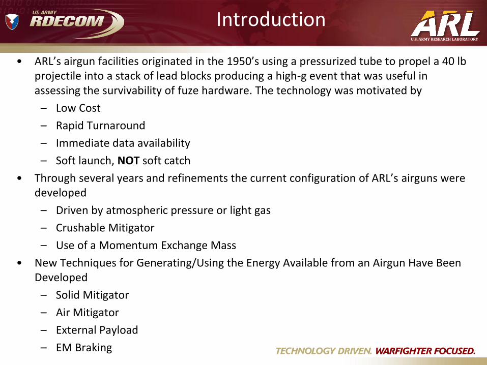
Simplified Momentum Transfer Equation
Momentum
Exchange Mass
Uncrushed
Mitigator
Crushed
Mitigator
Bird
(Test Article)
Mb vb
Mcm vcm
Mum vum
Mmem vmem
Initial Velocity (v0)
memmemtotal
memmemumbbcmtotal
ummem
cmb
btotal
umcmmit
vMp
tvMtMtvMtMp
vv
vv
vMp
MMM
:ImpactAfter
)()()()(
MEMjoinsmitigatoruncrushed
birdjoinsmitigatorcrushed
:ImpactDuring
:impacttoPrior
:MassMitigator
0

U.S. ARMY RESEARCH LABORATORY
Comparison to 155mm Artillery Launch M
easure
d A
ccele
ration
0.006 0.007 0.008 0.009 0.01 0.011 0.012 0.013 0.014 0.015-2000
0
2000
4000
6000
8000
10000
12000
14000
16000
18000
Time
Accel (g
)
Radial
Axial
155mm Cannon Launch
ARL 7” Airgun
Dynamic Environment Comparable to 155mm Cannon Launch
High
Pass
Filter
SRS

U.S. ARMY RESEARCH LABORATORY
Various Measured and Predicted Acceleration Profiles
U.S. ARMY RESEARCH LABORATORY
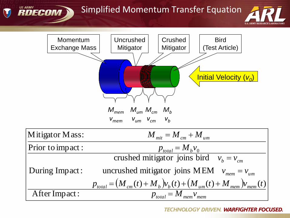
Combined Setback and Spin Environment Capability
3” Spinner Test Article in Spinner
1. Bird enters spinner and engages mitigator beginning the acceleration pulse 2. The bird is rapidly coupled to the spinner via frictional forces and the
mitigator 3. Bird experiences simultaneous setback and spin environment comparable
to launch from a rifled cannon
Spinning
Test Section
Spinning
Test Section

U.S. ARMY RESEARCH LABORATORY
Solid Mitigator
• Solid Mitigator Permits much High Acceleration Environments (100+ k-g)
• Pulse Length is much Shorter
• Understanding Crush Process of Solid Mitigator is Critical to Its Design

U.S. ARMY RESEARCH LABORATORY
Air Mitigator Technique
MAT'L 7075-T6
17.5 18 18.5 19 19.5 20 20.5 21 21.5
0
5
10
15
20
Setb
ack
Acc
eler
atio
n (
k-g
)
MAT'L 7075-T6
MAT'L 7075-T6
Impact Duration (msec)
Test article (red) is prepositioned in the pressure tube
with ground instrumentation. Energy Projectile (blue)
exits the airgun muzzle.
Energy projectile enters pressure tube and builds up
pressure against test article (red). Test article (red)
accelerates creating acceleration pulse.
At conclusion test article (red) is stopped by crushing
mitigator (green).
Airgun Catch Tube Pressure Tube

U.S. ARMY RESEARCH LABORATORY
Air Mitigator Differences
0
1
2
3
4
5
6
7
8
9
0.000 0.001 0.002 0.003 0.004 0.005 0.006 0.007 0.008
Time, sec
Acc
eler
atio
n, k
-g Test-
FE- Shot 5: 11 k-g Shot 4: 8 k-g
0.00
10k
20k
0.0254 0.0304 0.0280 Time (seconds)
Data filtered at sensor maximum frequency of 20 kHz
Pre
ssu
re (
psi
)
FE Vs. Measured Pressure Loading Function
•Test article can be measured with unlimited
channels by ground instrumentation
•No contact during test pulse
•Direct measurement of forcing function
•Test article must be soft-stopped
•Smooth loading pulse

U.S. ARMY RESEARCH LABORATORY
External Payload Airgun Operation
After Impact
Mitigator MEM
Before Impact Catch Tube Bird
Gun Muzzle
1. Bird is slowly accelerated in airgun by pressured gas or atmospheric pressure.
2. Bird exist muzzle and enters catchtube.
3. In catchtube, bird crushes shaped Al honeycomb mitigator to generated desired acceleration profile.
4. Test article remains stationary in catch tube and MEM exits back end of catch tube.
Test Article
MEM Test Article

U.S. ARMY RESEARCH LABORATORY
External Payload Example
Before Impact
MEM 2 Bird Miti gator
After Impact
MEM 1
Catch Tube
Seat & ATD
Plywood
MEM 2 Bird
Gun Muzzle
Mitigator
MEM 1
0.02 0.03 0.04 0.05 0.06 0.07 0.08 0.09 Time (s)
0
-200
-100
100
200
300
Accel (g
)
Acceleration, Accels filtered at 3 khz
Camera, Camera, Camera, MEM 1, Axial MEM 2, Axial
0.02 0.03 0.04 0.05 0.06 0.07 0.08 0.09 -4
-2
0
2
4
6
8
10
Time (s)
Velo
city
(m/s
)
Velocity (integral of filtered data)
Cam L1 Cam L2 Cam L3
Acceleration Velocity

U.S. ARMY RESEARCH LABORATORY
Electromagnetic Method
• In FY09 (phase I) proposals were solicited for an SBIR topic “High-G Simulator for In-Flight Test Article.”
– Develop a technology that can simulate the interior ballistic environment of a cannon launch as well as other high acceleration events.
– Deliver a concept capable of stopping a 60 lb projectile traveling at 900 ft/s with a deceleration pulse that varies from 5 k-g to 50 k-g and a duration that varies from 1 ms to 5 ms.
• In FY12 a two year phase II award was made to deliver a prototype device for use with the 3” airgun capable of the following:
Projectile Mass (lb)
Projectile Velocity (feet/sec)
Peak Acceleration (kilo-g)
Minimum Duration (ms)
5 280 15 1.0
5 750 50 1.5
1 600 15 2.5
1 1000 50 1
U.S. ARMY RESEARCH LABORATORY
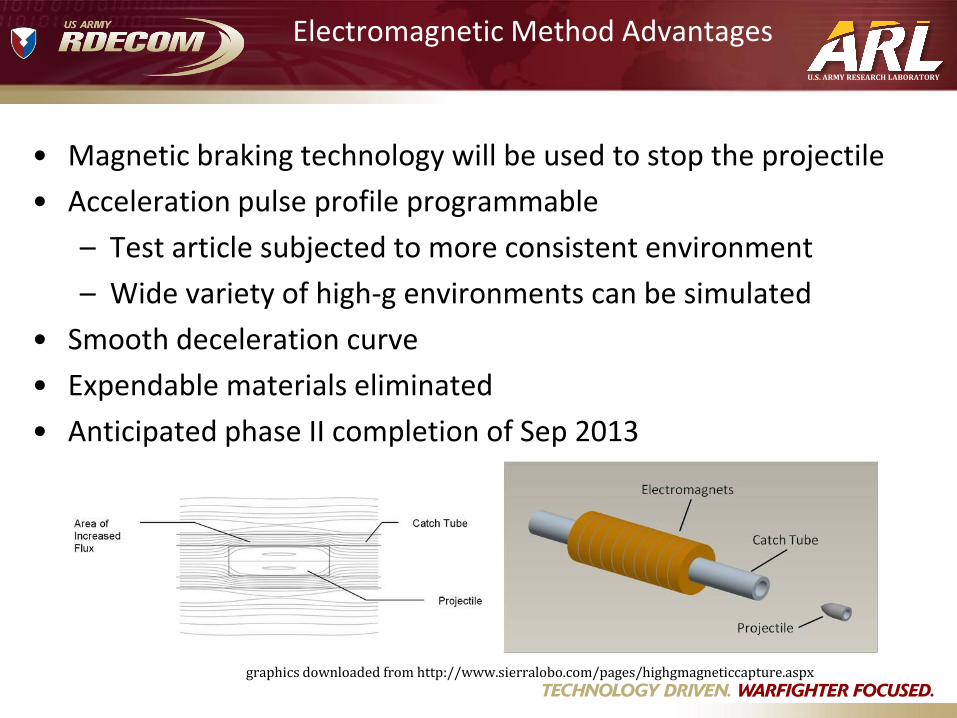
Electromagnetic Method Advantages
• Magnetic braking technology will be used to stop the projectile
• Acceleration pulse profile programmable
– Test article subjected to more consistent environment
– Wide variety of high-g environments can be simulated
• Smooth deceleration curve
• Expendable materials eliminated
• Anticipated phase II completion of Sep 2013
graphics downloaded from http://www.sierralobo.com/pages/highgmagneticcapture.aspx

U.S. ARMY RESEARCH LABORATORY
135 lbs 102 lbs
6 lbs 1.5 lbs 0.71 lbs 0.44 lbs 53 lbs
Summary
• Low Cost High-g Simulation Environment
• Immediate Test Article Availability Post-Test,
• Soft Launch NOT Soft Catch
• Highly Flexible Configuration
– ARL’s Conventional Airgun
• Up to 7” diameter test articles
• Up to 100 lb projectile
• Up to 200 k-g
• Up to 2000 ft/s
– Electromagnetic Method
• Digitally programmable pulse profile
• Highly repeatable environment
– Air Mitigator Technology
• Smooth loading curves
• Direct forcing function measurement
• Ground based instrumentation
– External Payload
• Unlimited test article volume & mass (acceleration dependent)
• Ground based instrumentation