Embed Size (px)
DESCRIPTION
New Steam Age
Citation preview
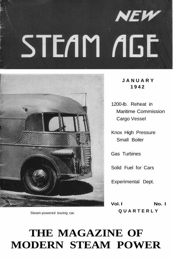
Steam-powered touring car.
J A N U A R Y1 9 4 2
1200-lb. Reheat in
Maritime Commission
Cargo Vessel
Knox High Pressure
Small Boiler
Gas Turbines
Solid Fuel for Cars
Experimental Dept.
Vol. I No. I
Q U A R T E R L Y
THE MAGAZINE OFMODERN STEAM POWER
In its first few issues, NEW STEAM AGE willnot accept any advertising. When its rate of growthhas become stabilized, when the soundness of itsreasons for existence has been demonstrated, adver-tising will be solicited. Meanwhile, if readers wishto be placed in touch with manufacturers of anyequipment mentioned in NEW STEAM AGE, theservices of the editorial department, which maintainsup-to-date files on products for this purpose, areavailable to subscribers.
Another reason for this policy is the possibility ofa change in the publishing schedule. If it appears thatthe service rendered by NSA can be increased there-by, more frequent publication will be considered.For the first issues, the three-month interval providestime for the careful checking and rechecking ofmaterial demanded by a new scientific magazine.With subscriptions rolling in at press-time, and ex-pressions of reader interest already appearing, an in-crease in the number of pages, in illustrations, and adevelopment of some of the departments now in aformative state, seems highly probable.
Vol. 1 January 1942 No. I
Copyright 1941 by New Steam Age, Stonington,Connecticut. Printed by Stonington Publ i sh ing Co.
NEW STEAM AGENext Issue
The editors have been gathering in-formation on gas generators, first be-cause they are an inexpensive methodof converting any automobile for theuse of a cheap fuel, and second, be-cause the principle of the down-draftgas producer is worth exploring, forits possibilities as an automatic firingsource for steam boilers. ModernEuropean practice in automotive useof gas generators will be described.
Fundamental preliminary design ofa steam automobile, from powerplantto body style, is the subject of an ar-ticle by a painstaking researcher onautomotive subjects. Once an execu-tive of a well-known motor car com-pany, and now engaged in the machinetool industry, the author has the ex-perience and engineering knowledge toevaluate problems in as diverse fieldsas aerodynamics, heat-loss, and pro-duction, and apply his conclusion in anorderly manner to a specific designproblem—a modern steam car.
Concluding the description of theKnox steam plant, (the boiler is des-cribed in this issue) a report on thedesign, construction, and testing of theKnox compound engine, will illustratethe "works" of this interesting uni-flow engine and unique valve gear.
Our marine department has beenactive and successful in ferreting outsome unusual installations of high-pressure propulsion machinery. Andseveral steam vessels have been onlong and eventful maiden voyages.
Contents
Editorial B o w . . . . ' . page 2
Marine News. High pressure inthe Merchant Marine. page 3
Gas Generators for AutomotiveUse page 4
Hero II, One-Man Steam YachtFirst of two articles.. page 5
The Gas Turbine. By Dr. J. T.Rettaliata page 7
The Hunt Steam TouringCar page 11
Knox Boiler. The first of two re-ports on a high-output steamplant of small s i z e . . page 14
A Modern Steam C a r . . page 18
Steam Motor AssociationNotes page 21
Published Quarterly by
New Steam AgeStonington, Connecticut
JOHN W. LINCOLN, Editor
BYRON SPENCE, Contributing Editor
CAPT. ELWELL B. THOMAS, Marine Editor
Volume I Number IJanuary, 1942
$2. 00 per year in United States($2. 50 in Canada, Territorial Possessions,
Central and South America, Cuba. )
New Steam Age, January, 1942 Page 1

Blow-off
From many conversations over a period of years, from many friendlyletters, and encouraging signs in the daily press, the concept of an Americanmagazine devoted entirely to modern steam power, has gradually taken shapein the minds of our editors and many of our "First Readers".
There have been other magazines on this subject, but the last to be pub-lished in this country expired long ago. The reasons for its passing wereobvious: the steam automobile was disappearing from the highway. The GasAge was in full swing. Automobiles had become a means of transport ratherthan a source of sport. The Sunday morning major overhaul in the alley, oncea joy to the mechanically inclined office worker, has faded into the past—almost.The silent and graceful steam launches of our lakes and harbors had given wavto the "put-puts". Steam was still useful in huge power plants, ocean liners,and locomotives, but it lost popular favor, and its days seemed numbered.Even the Turkish bath was on the skids.
Why do we, Phoenix-like, rise from these ashes? What has happenedto provoke the publication of a new magazine, especially in these unsettledtimes? In the last two decades, steam has reached new heights of economyand ease of control. Since the Stanley Steamer ceased to be the "best performer"on the highway, the "flash" boiler has been perfected, the automatic atomizingoil burner has been installed in millions of homes, lubricating oils have beenimproved, and metals that retain strength and wearing qualities at high temp-eratures are available—with a priority order. The capabilities of steam as alight weight power plant have been demonstrated by successful flights of asteam-powered aircraft. In many vehicles, ships, and stationery plants, ingreat laboratories and in backwoods machine shops, steam is being re-investi-gated, revaluated, and "streamlined" to perform tasks that Watt would haveconsidered miraculous.
It will be our steadfast purpose to keep abreast of these investigations, toreport the greatest and the least of them with unbiased scientific zeal, to stimu-late and correlate these efforts, and to promote insofar as possible a sound un-derstanding of the merits of steam power, without failing to recognize thesometimes superior qualities of other prime movers. We shall also take a gen-eral interest in fuel conservation in transportation, in domestic heating, andother fields.
Of course, we will relax sometimes. The history of steam is so full ofhuman and mechanical complexities that we will not be able to resist an occa-sional story on steam plants of the past. And a good piece of model engineeringis not beneath notice.
—The Editors
Page 2 New Steam Age, January, 1942
1200-lb. Reheat Marine PlantBenjamin Fox and Richard H. Tingey*
The following extracts from apaper presented at the annual meetingof the Society of Naval Architects andMarine Engineers describe briefly themost important features of this un-usual installation, sponsored by theMaritime Commission for operationby American Export Lines. Throughthe cooperation of the authors, the So-ciety, and the Maritime Commission,NEW STEAM AGE is privileged tobe among the first to announce thisimportant milestone in the history ofsteam power.
The S. S. Examiner is one of a classof eight 45O-foot cargo ships, knownas the C-3 design, built by the Beth-lehem Steel Company. The machineryplant consists of single-screw, double-reduction geared turbines of 8000shaft horsepower. The steam condi-tions of seven vessels of the group are425 lbs. and 740° F. at the throttle.The design and performance charac-teristics are generally in accordancewith the best current practice.
When the group was about halfcompleted, the Commission arrangedwith the builders and the operators tochange the design of the machinery forthe eighth vessel to a 1200-lb reheatinstallation. The complete redesignwas worked out by the shipbuilderwith the cooperation of the MaritimeCommission and the manufacturers ofthe boilers, turbines, and auxiliaries.The intent was to determine, by full-scale experiment, the suitability of
* Assistant Manager of Enginering, and ChiefEngineer, respectively, of Bethlehem SteelCo., Shipbuilding Division.
such machinery for marine propulsion,particularly with a view to adoptionof the cycle for the Commission's con-templated large high-powered passen-ger vessels.
The changes were confined to thoseinherent in the new steam conditions,and the S. S. Examiner therefore dif-fers only in the turbines, boilers, andequipment intimately connected withthe heat cycle. An excellent opportun-ity is here presented to compare 'thetwo types in the same service. Exhaus-tive trials are contemplated when theinstallation, now nearly complete, is inoperation.
The characteristic features of thereheat cycle can be explained by refer-ence to the following description ofthe steam path:
(1) Steam is generated and super-heated in conventional boiler andsuperheater elements. (2) The steamis then expanded through the high-pressure elements of the turbine to thereheater inlet pressure. (3) It is thenreheated at this reduced pressure inthe reheater elements. (4) The re-heated steam is finally expanded in thelow-pressure elements of the turbinedown to vacuum and is then condens-ed.
The steam leaving the high-pressureturbine may be heated by flue gases orby live steam at boiler temperatureand pressure. Both of these methodshave been applied in land plants; inmarine practice an application wasmade in the Loeffler boiler in the S. S.Conti Rosso. The installation underdiscussion has separate furnaces and
(Continued on page 20)
New Steam Age, January, 1942 Page 3
Gas Generators For Automotive Use
With increasing frequency sinceWorld War I there have been wavesof interest in substitute motor fuels,particularly in Europe. In the UnitedStates the abundance of petroleumhas prevented any serious study ofsmall gas producers. With possible di-version of oil supplies to military usesin view, a study of the gas generatorseems appropraite.
The Dim Past
The gas producer has been in ex-istence since the beginning of iron pro-duction in furnaces. In the first part ofthe 19th century it was discoveredthat the gas evolving from the reduc-tion of iron with coal could be utilizedfor heating air, operating blowers, andother equipment around the furnace.In 1835 William Barnett, working onthe earlier ideas of Lebon, inventor ofilluminating gas, designed a motor for
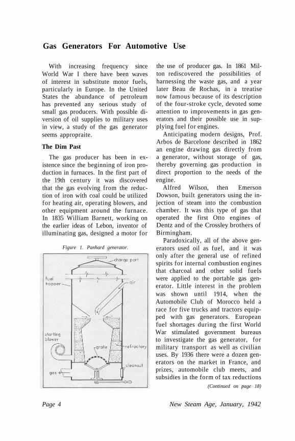
Figure 1. Panhard generator.
the use of producer gas. In 1861 Mil-ton rediscovered the possibilities ofharnessing the waste gas, and a yearlater Beau de Rochas, in a treatisenow famous because of its descriptionof the four-stroke cycle, devoted someattention to improvements in gas gen-erators and their possible use in sup-plying fuel for engines.
Anticipating modern designs, Prof.Arbos de Barcelone described in 1862an engine drawing gas directly froma generator, without storage of gas,thereby governing gas production indirect proportion to the needs of theengine.
Alfred Wilson, then EmersonDowson, built generators using the in-jection of steam into the combustionchamber. It was this type of gas thatoperated the first Otto engines ofDentz and of the Crossley brothers ofBirmingham.
Paradoxically, all of the above gen-erators used oil as fuel, and it wasonly after the general use of refinedspirits for internal combustion enginesthat charcoal and other solid fuelswere applied to the portable gas gen-erator. Little interest in the problemwas shown until 1914, when theAutomobile Club of Morocco held arace for five trucks and tractors equip-ped with gas generators. Europeanfuel shortages during the first WorldWar stimulated government bureausto investigate the gas generator, formilitary transport as well as civilianuses. By 1936 there were a dozen gen-erators on the market in France, andprizes, automobile club meets, andsubsidies in the form of tax reductions
(Continued on page 18)
Page 4 New Steam Age, January, 1942
Hero II, One-Man Steam YachtBy Capt. A. Vapeur
During the fitting-out period, curi-osity brought many amateur and pro-fessional skippers to the dock, somehoping to see an explosion, some seek-ing enlightenment, others just plaincurious. When reports reached methat Hero was making trial runs, Ilost no time in getting to the water-front.
The stack distinguished Hero fromother cruisers at the dock. I foundthe owner absorbed in some carpentry,and "Gus, " the "crew, " busy belowputting down a fine red linoleum sinktop. The engine hatch was raised formy entertainment, and Mr. York, theowner, proceeded with his carpentry.I was soon absorbed in trying to fol-low wires and pipes around the boilerunit, a confusing task because of theheavy insulation on all the parts, andI failed to notice that the owner's taskwas over. When I next looked up
from the bilge, we were a dozen yardsfrom the dock. Mr. York had castoff the lines and stepped to the bridgeto open the throttle. We were movingsmoothly out into the harbor, and fora moment I felt the strange excitingsensation that comes over one as aliner sails. The silence, the absenceof vibration, and the mysterious chang-ing perspective of the shore, all con-vinced me that I was aboard a genu-ine steamer.
As the dock disappeared astern, Ipulled my wits together, and went tothe bridge to discover what the gageswere saying, secretly hoping that Mr.York would let me take the helm. Afaint purring noise below the hatchindicated that the burner was on, re-sponding automatically to the need formore steam as speed increased. Theowner asked if I would mind takingthe wheel. Trying not to show too
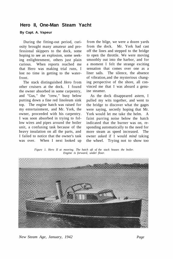
Figure 1. Hero II at mooring. The hatch aft of the stack houses the boiler.Engine is forward, under floor.
New Steam Age, January, 1942 Page
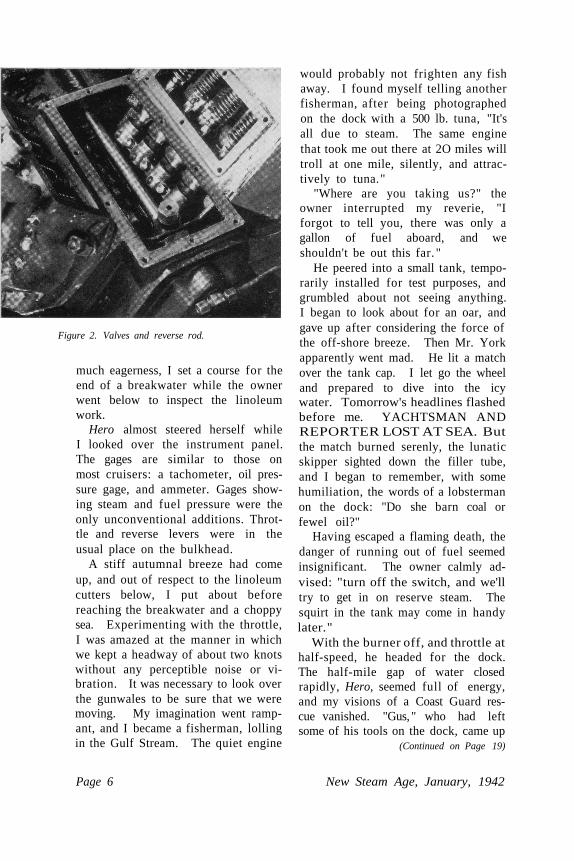
Figure 2. Valves and reverse rod.
much eagerness, I set a course for theend of a breakwater while the ownerwent below to inspect the linoleumwork.
Hero almost steered herself whileI looked over the instrument panel.The gages are similar to those onmost cruisers: a tachometer, oil pres-sure gage, and ammeter. Gages show-ing steam and fuel pressure were theonly unconventional additions. Throt-tle and reverse levers were in theusual place on the bulkhead.
A stiff autumnal breeze had comeup, and out of respect to the linoleumcutters below, I put about beforereaching the breakwater and a choppysea. Experimenting with the throttle,I was amazed at the manner in whichwe kept a headway of about two knotswithout any perceptible noise or vi-bration. It was necessary to look overthe gunwales to be sure that we weremoving. My imagination went ramp-ant, and I became a fisherman, lollingin the Gulf Stream. The quiet engine
would probably not frighten any fishaway. I found myself telling anotherfisherman, after being photographedon the dock with a 500 lb. tuna, "It'sall due to steam. The same enginethat took me out there at 2O miles willtroll at one mile, silently, and attrac-tively to tuna. "
"Where are you taking us?" theowner interrupted my reverie, "Iforgot to tell you, there was only agallon of fuel aboard, and weshouldn't be out this far. "
He peered into a small tank, tempo-rarily installed for test purposes, andgrumbled about not seeing anything.I began to look about for an oar, andgave up after considering the force ofthe off-shore breeze. Then Mr. Yorkapparently went mad. He lit a matchover the tank cap. I let go the wheeland prepared to dive into the icywater. Tomorrow's headlines flashedbefore me. YACHTSMAN ANDREPORTER LOST AT SEA. Butthe match burned serenly, the lunaticskipper sighted down the filler tube,and I began to remember, with somehumiliation, the words of a lobstermanon the dock: "Do she barn coal orfewel oil?"
Having escaped a flaming death, thedanger of running out of fuel seemedinsignificant. The owner calmly ad-vised: "turn off the switch, and we'lltry to get in on reserve steam. Thesquirt in the tank may come in handylater. "
With the burner off, and throttle athalf-speed, he headed for the dock.The half-mile gap of water closedrapidly, Hero, seemed full of energy,and my visions of a Coast Guard res-cue vanished. "Gus, " who had leftsome of his tools on the dock, came up
(Continued on Page 19)
Page 6 New Steam Age, January, 1942
The Gas TurbineDr. J. T. Rettaliata*
Few, if any, other mechanisms havehad as much time and effort devotedto their development, and with suchlimited success, as the gas turbineprior to the present combustion type.Apparently misled by its ostensiblesimplicity, innumerable inventors haveexperienced repeated failures in theirattempts to achieve a successful gasturbine. It is logical to inquire why apractical design was not evolved dur-ing these many years of experimenta-tion.
Referring particularly to the com-bustion gas turbine, the only type toattain commercial significance up tothe present time, the main obstaclesconfronting the early investigatorswere twofold—first, the inability ofthe then existent materials to with-stand the high temperatures necessaryto produce suitable cycle efficiencies;and, second, the lack of a compressorof adequate efficiency to make the cy-cle feasible. Metallurgical and aero-dynamical advances have overcomeboth of these difficulties. The superiormaterials available today permit theutilization of elevated temperatures,and progress in fluid flow research hasresulted in a highly efficient axial com-pressor.
The current increase in publicityconcerning the combustion gas tur-bine, both in this country and abroad,may have created the impression thatit is an invention of recent origin. To
* Steam Turbine Department, Allis-ChalmersManufacturing Co. Reprinted from the Allis-Chalmers Electrical Review. The first articleof a series on this subject.
dispel such an erroneous conception,the following section, dealing brieflywith the general background of thegas turbine, will serve to demonstratethe antiquity associated with the art.
Earliest History
The first device that could be in-cluded in the category of gas turbineswas devised by Hero of Alexandria in130 B. C. The purpose of the machinewas to impart motion to symbolic fig-ures on an altar. The heating of air ina vertical tube induced air in severalradially displaced tubes, and rotationresulted from the creation of an im-pulse effect.
Although the date of its origin isobscure, the windmill may be consid-ered as a gas turbine. The principle ofthe medieval "Smokejack" was prac-tically identical to that of the wind-mill, thus leading to the belief that itsinventor may have received inspira-tion from the latter. The smokejackwas placed in a chimney and rotationinduced by the passage of flue gasesthrough the bladed wheel. While ofquestionable utility, it was claimedthat it performed certain limited func-tions.
Many other references to variouscontrivances which may be classifiedas gas turbines are revealed by a sur-vey of old literature. In 1791 JohnBarber, of England, obtained a patenton the first machine to bear an intrin-sic resemblance to the modern com-bustion gas turbine. Although primi-tive in form, it comprised all of theessential features of a present day
New Steam Age, January, 1942 Page 7
unit. Barber's patent drawings showcompressors for both air and gas mix-ture, and an impulse type turbinewheel on which impinged the highvelocity jet of gases leaving the nozzlein one extremity of the combustionchamber. To prevent the subjection ofthe turbine parts to excessive tempera-tures, a provision for cooling the gasesby water injection was also indicated.
John Dumbell, also of England,patented in 1808 a device which was aprototype of the "explosion" type ofgas turbine to be described more fullylater. Products of combustion trav-ersed a turbine rotor comprising sev-eral rows of blading. The design couldhardly be considered propitious, how-ever, since it consisted entirely of ro-tating blading and did not includestationary or guide elements, therebydepriving it of the advantages of thepresent day multi-stage type of tur-bine.
A machine whose essential featuresresembled those of a turbine used inthe Armengaud and Lemale experi-ments, to be recounted later, was pat-ented by Bresson in Paris in 1837. Afan delivered air under pressure to acombustion chamber where it mixedwith gaseous fuel, burned, and theproducts of combustion, cooled by ex-cess air, directed in the form of a jetonto a wheel.
Forerunners of Present Types
Other gas turbine schemes wereproposed during this period, but they,as well as those mentioned above, ex-hibited various features of designwhich rendered them impracticable.In 1872, however, a patent for a "fireturbine" was applied for by Dr. F.Stolze, of Charlottenburg. The sim-ilarity between the Stolze gas turbine
and the modern combustion type is in-deed striking. The unit consisted ofan axial flow compressor directlycoupled to a reaction turbine. Beforeexpansion through the turbine, air dis-charged from the compressor washeated in an externally fired chamber.Tests on an actual unit indicated thedesign was unsuccessful primarily be-cause of the inadequacy of the axialcompressor. In view of the limitedknowledge of aerodynamics existing atthat time, such unfavorable resultscould be expected.
In 1884 Sir Charles Parsons ob-tained his original steam turbine pa-tent, and in it reference was made tothe gas turbine. It was explained thatthe turbine could be converted into acompressor by driving it in a reversedirection by an external means. Thecompressed air was discharged into afurnace where fuel was injected, andthe resulting products of combustionwere expanded through a turbine. Ex-cept for blade contours and angles,the compressor was similar to theaxial compressor as it is known today.The patent also provided for the cool-ing of the turbine blades by eitherwater or other suitable fluid.
During the years 1900-08 the Par-sons Company built about 30 axialcompressors, the largest having a ca-pacity of 50, 000 cfm. The highest de-livery pressure of any of the units was11. 75 psi gauge. Much effort was ex-pended with inconsequential successin improving the efficiency of the axialcompressor. Primarily because of hisnumerous other activities but also be-cause of the higher efficiency centri-fugal compressor of Rateau, introduc-ed commercially in 1908, Sir Charlesfinally abandoned further research onthe axial compressor.
Page 8 New Steam Age, January, 1942
First Practical Gas Turbines
The Societe des Turbo-moteurs inParis during the years 1903 to 1906built several experimental gas turbinesoperating on a cycle similar to that ofthe modern combustion gas turbine.The work, really the first significantattempt at building a practical gas tur-bine, was performed by Armengaudand Lemale. The results of the origin-al tests obtained on a 25 hp DeLavalturbine led to the construction of aturbine of higher capacity, consistingof a two-row impulse wheel with pro-vision for water cooling of the bladesand disk.
Compressed air from a multi-stageRateau compressor driven by the tur-bine was supplied to a combustionchamber in which liquid fuel wasburned. The resulting combustiongases, cooled by water injection, wereexpanded through the turbine. A ther-mal efficiency of slightly less than
three percent was obtained. Notwith-standing this poor performance, theexperiments were significant becausethis was probably the first combustiongas turbine to actually produce usefulwork.
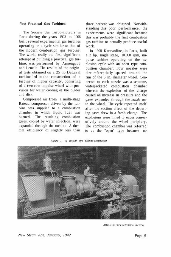
In 1908 Karavodine, in Paris, builta 2 hp, single stage, 10, 000 rpm, im-pulse turbine operating on the ex-plosion cycle with an open type com-bustion chamber. Four nozzles werecircumferentially spaced around therim of the 6 in. diameter wheel. Con-nected to each nozzle was a separate,waterjacketed combustion chamberwherein the explosion of the chargecaused an increase in pressure and thegases expanded through the nozzle on-to the wheel. The cycle repeated itselfafter the suction effect of the depart-ing gases drew in a fresh charge. Theexplosions were timed to occur consec-utively around the wheel periphery.The combustion chamber was referredto as the "open" type because no
Figure 1. A 40, 000 cfm turbine-compressor
Allis-Chalmers Electrical Review
New Steam Age, January, 1942 Page 9
valves were placed between the ex-plosion region and the nozzle inlet,compression being effected by the in-ertia of the burning gas mixture. Al-though the turbine reputedly operatedsatisfactorily, the overall thermal ef-ficiency amounted to less than threepercent.
Holzwarth Turbines
In 1908 Dr. Hans Holzwarth be-gan his long years of experimentalwork on the explosion type of gas tur-bine which bears his name. The con-tinued activity and interest exhibitedin this turbine by Holzwarth and oth-ers has persisted to the present day.The Holzwarth turbine operates onthe explosion or Otto cycle, the ex-pansion phase of the cycle extendingto atmospheric pressure. The explo-sion occurs upon ignition of a chargeof air and gas introduced under pres-sure into the combustion chamber.The pressure in the closed chamber in-creases until it overcomes the actionof a spring-loaded valve, permittingthe gases to flow to a nozzle whencethey are discharged at high velocityonto a turbine wheel. The nozzlevalve is specially constructed so that itremains open under oil pressure untilthe combustion chamber is emptied.Expansion is followed by a scavengingoperation which clears the combustionchamber of residual burnt gases andalso cools the turbine blades. Afterscavenging, a fresh charge is admittedand the cycle repeated.
Precompression of the charge wasnot provided in the first turbine builtby Holzwarth, but later ones had amoderate amount produced by a steamturbine-driven compressor. A waste
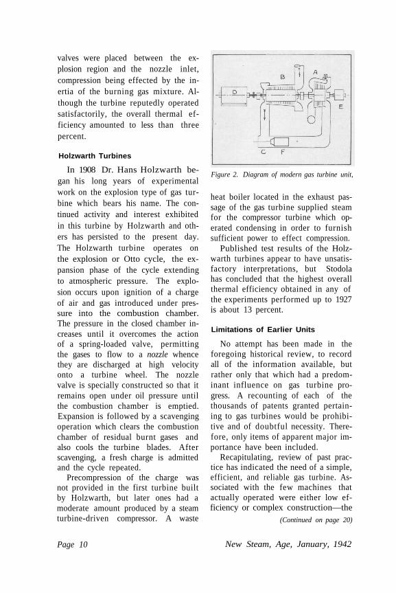
Figure 2. Diagram of modern gas turbine unit,
heat boiler located in the exhaust pas-sage of the gas turbine supplied steamfor the compressor turbine which op-erated condensing in order to furnishsufficient power to effect compression.
Published test results of the Holz-warth turbines appear to have unsatis-factory interpretations, but Stodolahas concluded that the highest overallthermal efficiency obtained in any ofthe experiments performed up to 1927is about 13 percent.
Limitations of Earlier Units
No attempt has been made in theforegoing historical review, to recordall of the information available, butrather only that which had a predom-inant influence on gas turbine pro-gress. A recounting of each of thethousands of patents granted pertain-ing to gas turbines would be prohibi-tive and of doubtful necessity. There-fore, only items of apparent major im-portance have been included.
Recapitulating, review of past prac-tice has indicated the need of a simple,efficient, and reliable gas turbine. As-sociated with the few machines thatactually operated were either low ef-ficiency or complex construction—the
(Continued on page 20)
Page 10 New Steam, Age, January, 1942
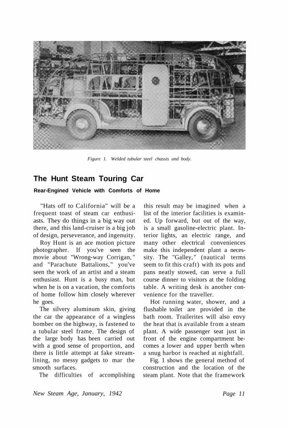
Figure 1. Welded tubular steel chassis and body.
The Hunt Steam Touring CarRear-Engined Vehicle with Comforts of Home
"Hats off to California" will be afrequent toast of steam car enthusi-asts. They do things in a big way outthere, and this land-cruiser is a big jobof design, perseverance, and ingenuity.
Roy Hunt is an ace motion picturephotographer. If you've seen themovie about "Wrong-way Corrigan, "and "Parachute Battalions, " you'veseen the work of an artist and a steamenthusiast. Hunt is a busy man, butwhen he is on a vacation, the comfortsof home follow him closely whereverhe goes.
The silvery aluminum skin, givingthe car the appearance of a winglessbomber on the highway, is fastened toa tubular steel frame. The design ofthe large body has been carried outwith a good sense of proportion, andthere is little attempt at fake stream-lining, no messy gadgets to mar thesmooth surfaces.
The difficulties of accomplishing
this result may be imagined when alist of the interior facilities is examin-ed. Up forward, but out of the way,is a small gasoline-electric plant. In-terior lights, an electric range, andmany other electrical conveniencesmake this independent plant a neces-sity. The "Galley, " (nautical termsseem to fit this craft) with its pots andpans neatly stowed, can serve a fullcourse dinner to visitors at the foldingtable. A writing desk is another con-venience for the traveller.
Hot running water, shower, and aflushable toilet are provided in thebath room. Trailerites will also envythe heat that is available from a steamplant. A wide passenger seat just infront of the engine compartment be-comes a lower and upper berth whena snug harbor is reached at nightfall.
Fig. 1 shows the general method ofconstruction and the location of thesteam plant. Note that the framework
New Steam Age, January, 1942 Page 11
of the body is cut away behind thesteam unit, to facilitate removal of theplant as a whole for service.
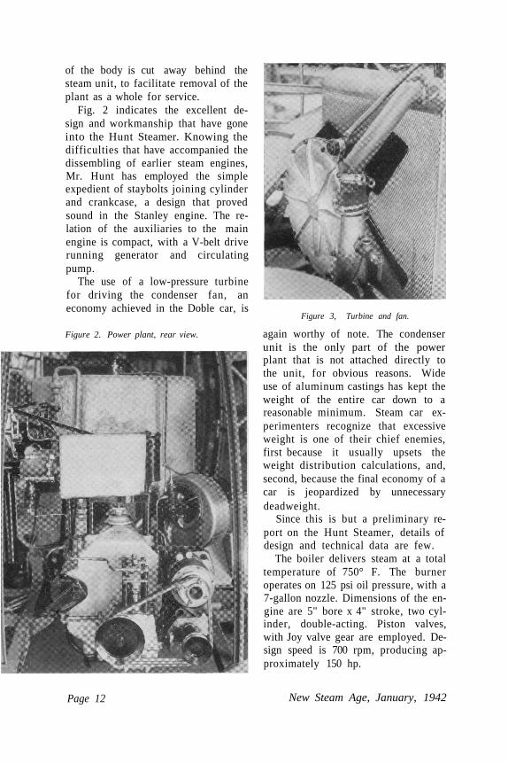
Fig. 2 indicates the excellent de-sign and workmanship that have goneinto the Hunt Steamer. Knowing thedifficulties that have accompanied thedissembling of earlier steam engines,Mr. Hunt has employed the simpleexpedient of staybolts joining cylinderand crankcase, a design that provedsound in the Stanley engine. The re-lation of the auxiliaries to the mainengine is compact, with a V-belt driverunning generator and circulatingpump.
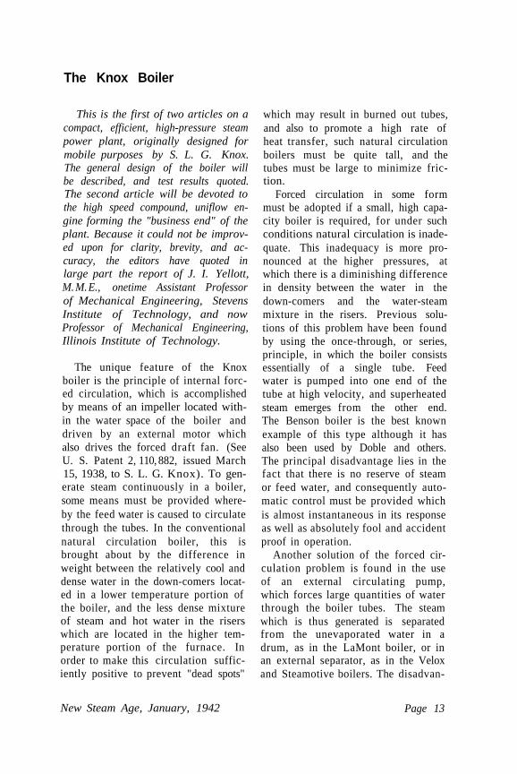
The use of a low-pressure turbinefor driving the condenser fan, aneconomy achieved in the Doble car, is
Figure 3, Turbine and fan.
again worthy of note. The condenserunit is the only part of the powerplant that is not attached directly tothe unit, for obvious reasons. Wideuse of aluminum castings has kept theweight of the entire car down to areasonable minimum. Steam car ex-perimenters recognize that excessiveweight is one of their chief enemies,first because it usually upsets theweight distribution calculations, and,second, because the final economy of acar is jeopardized by unnecessarydeadweight.
Since this is but a preliminary re-port on the Hunt Steamer, details ofdesign and technical data are few.
The boiler delivers steam at a totaltemperature of 750° F. The burneroperates on 125 psi oil pressure, with a7-gallon nozzle. Dimensions of the en-gine are 5" bore x 4" stroke, two cyl-inder, double-acting. Piston valves,with Joy valve gear are employed. De-sign speed is 700 rpm, producing ap-proximately 150 hp.
Page 12 New Steam Age, January, 1942
Figure 2. Power plant, rear view.
The Knox Boiler
This is the first of two articles on acompact, efficient, high-pressure steampower plant, originally designed formobile purposes by S. L. G. Knox.The general design of the boiler willbe described, and test results quoted.The second article will be devoted tothe high speed compound, uniflow en-gine forming the "business end" of theplant. Because it could not be improv-ed upon for clarity, brevity, and ac-curacy, the editors have quoted inlarge part the report of J. I. Yellott,M. M. E., onetime Assistant Professorof Mechanical Engineering, StevensInstitute of Technology, and nowProfessor of Mechanical Engineering,Illinois Institute of Technology.
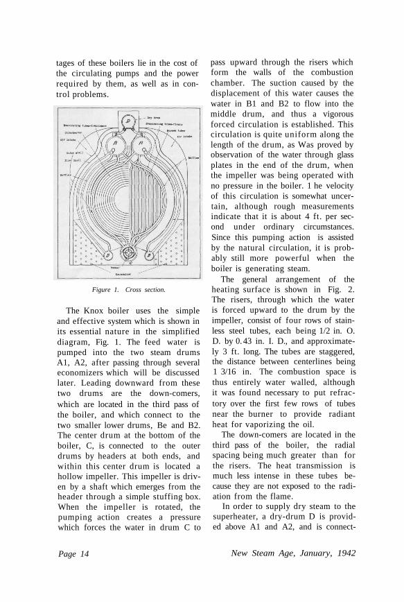
The unique feature of the Knoxboiler is the principle of internal forc-ed circulation, which is accomplishedby means of an impeller located with-in the water space of the boiler anddriven by an external motor whichalso drives the forced draft fan. (SeeU. S. Patent 2, 110, 882, issued March15, 1938, to S. L. G. Knox). To gen-erate steam continuously in a boiler,some means must be provided where-by the feed water is caused to circulatethrough the tubes. In the conventionalnatural circulation boiler, this isbrought about by the difference inweight between the relatively cool anddense water in the down-comers locat-ed in a lower temperature portion ofthe boiler, and the less dense mixtureof steam and hot water in the riserswhich are located in the higher tem-perature portion of the furnace. Inorder to make this circulation suffic-iently positive to prevent "dead spots"
which may result in burned out tubes,and also to promote a high rate ofheat transfer, such natural circulationboilers must be quite tall, and thetubes must be large to minimize fric-tion.
Forced circulation in some formmust be adopted if a small, high capa-city boiler is required, for under suchconditions natural circulation is inade-quate. This inadequacy is more pro-nounced at the higher pressures, atwhich there is a diminishing differencein density between the water in thedown-comers and the water-steammixture in the risers. Previous solu-tions of this problem have been foundby using the once-through, or series,principle, in which the boiler consistsessentially of a single tube. Feedwater is pumped into one end of thetube at high velocity, and superheatedsteam emerges from the other end.The Benson boiler is the best knownexample of this type although it hasalso been used by Doble and others.The principal disadvantage lies in thefact that there is no reserve of steamor feed water, and consequently auto-matic control must be provided whichis almost instantaneous in its responseas well as absolutely fool and accidentproof in operation.
Another solution of the forced cir-culation problem is found in the useof an external circulating pump,which forces large quantities of waterthrough the boiler tubes. The steamwhich is thus generated is separatedfrom the unevaporated water in adrum, as in the LaMont boiler, or inan external separator, as in the Veloxand Steamotive boilers. The disadvan-
New Steam Age, January, 1942 Page 13
tages of these boilers lie in the cost ofthe circulating pumps and the powerrequired by them, as well as in con-trol problems.
Figure 1. Cross section.
The Knox boiler uses the simpleand effective system which is shown inits essential nature in the simplifieddiagram, Fig. 1. The feed water ispumped into the two steam drumsA1, A2, after passing through severaleconomizers which will be discussedlater. Leading downward from thesetwo drums are the down-comers,which are located in the third pass ofthe boiler, and which connect to thetwo smaller lower drums, Be and B2.The center drum at the bottom of theboiler, C, is connected to the outerdrums by headers at both ends, andwithin this center drum is located ahollow impeller. This impeller is driv-en by a shaft which emerges from theheader through a simple stuffing box.When the impeller is rotated, thepumping action creates a pressurewhich forces the water in drum C to
pass upward through the risers whichform the walls of the combustionchamber. The suction caused by thedisplacement of this water causes thewater in B1 and B2 to flow into themiddle drum, and thus a vigorousforced circulation is established. Thiscirculation is quite uniform along thelength of the drum, as Was proved byobservation of the water through glassplates in the end of the drum, whenthe impeller was being operated withno pressure in the boiler. 1 he velocityof this circulation is somewhat uncer-tain, although rough measurementsindicate that it is about 4 ft. per sec-ond under ordinary circumstances.Since this pumping action is assistedby the natural circulation, it is prob-ably still more powerful when theboiler is generating steam.
The general arrangement of theheating surface is shown in Fig. 2.The risers, through which the wateris forced upward to the drum by theimpeller, consist of four rows of stain-less steel tubes, each being 1/2 in. O.D. by 0. 43 in. I. D., and approximate-ly 3 ft. long. The tubes are staggered,the distance between centerlines being1 3/16 in. The combustion space isthus entirely water walled, althoughit was found necessary to put refrac-tory over the first few rows of tubesnear the burner to provide radiantheat for vaporizing the oil.
The down-comers are located in thethird pass of the boiler, the radialspacing being much greater than forthe risers. The heat transmission ismuch less intense in these tubes be-cause they are not exposed to the radi-ation from the flame.
In order to supply dry steam to thesuperheater, a dry-drum D is provid-ed above A1 and A2, and is connect-
Page 14 New Steam Age, January, 1942
ed to them by a number of smalltubes. Perforated metal screens arealso placed above the water line inA1 and A2 to prevent priming, orcarrying over of large slugs of water.
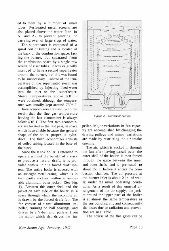
The superheater is composed of aspiral coil of tubing and is located atthe back of the combustion space, fac-ing the burner, but separated fromthe combustion space by a single rowscreen of riser tubes. It was originallyintended to have a second superheateraround the burner, but this was foundto be unnecessary. Control of the tem-perature of the superheated steam wasaccomplished by injecting feed-waterinto the inlet to the superheater.Steam temperatures above 800° Fwere obtained, although the tempera-ture was usually kept around 750° F.Three economizers are used, with the
result that the flue gas temperatureleaving the last economizer is alwaysbelow 400° F. The first two economiz-ers are located in the last pass, in spacewhich is available because the generalshape of the boiler proper is cylin-drical. The third economizer consistsof coiled tubing located in the base ofthe stack.
Since the Knox boiler is intended tooperate without the benefit of a stackto produce a natural draft, it is pro-vided with a unique forced draft sys-tem. The entire boiler is covered withan air-tight metal casing, which is inturn partly enclosed within a remov-able aluminum outer jacket. (See Fig.1). Between this outer shell and thejacket on each side of the boiler is aspace through which the incoming airis drawn by the forced draft fan. Thefan consists of a cast aluminum im-peller, running on ball bearings, anddriven by a V-belt and pulleys fromthe motor which also drives the im-
Figure 2. Horizontal section.
peller. Major variations in fan capac-ity are accomplished by changing thedriving pulleys and minor variationsare made by restricting the air intakeopening.
The air, which is sucked in throughthe fan after having passed over theouter shell of the boiler, is then forcedthrough the space between the innerand outer shells, and is preheated toabout 350 F before it enters the com-bustion chamber. The air pressure atthe burner inlet is about 2 in. of wat-er, under the usual operating condi-tions. As a result of this unusual ar-rangement of the air supply, the jack-et around the upper part of the boileris at almost the same temperature asthe surrounding air, and consequentlythe losses due to radiation and convec-tion are negligible.
The course of the flue gases can be
New Steam Age, January, 1942 Page 15
seen on Fig. 2. After passing throughthe coiled superheater at the rear ofthe combustion chamber, the gases di-vide and turn back through the secondpass, in which it was originally in-tended to locate more superheatertubes. Experience showed that the onecoil was enough and consequently infuture boilers this empty second passcould be put to good use, or the sizeof the boiler could be still further re-duced. Upon leaving the second pass,the gases go back through the thirdpass in which the down-comers are lo-cated. The gases then move down, asshown in Fig. 1, into the economizerspace, and again come to the front ofthe boiler, where they enter the head-er which leads to the last economizerand finally to the stack.
The usefulness of the last econ-omizer is demonstrated by the test re-sults, which show that the flue gastemperature in the header is about590° F at full load, while the gas tem-perature at the last economizer outletis about 380° F.
During the tests the flue gases weredischarged to the atmosphere througha 12 in. duct at a height of about 10ft. above the ground. The velocity ofthe gases at the duct outlet was about1200 fpm as determined by a Velo-meter.
The stack was entirely free fromsmoke during the tests, and in fact theair supply could probably have beenstill more reduced without causingsmoke.
The principal difficulty which wasencountered in the development of theKnox boiler was the smokeless andefficient combustion of fuel oil at ex-tremely high rates in a very smallchamber. The combustion equipmentwhich was in use when the tests were
run consisted of four main burners,arranged around a small pilot burner.The individual burners were locatedcentrally in venturi-shaped openingsthrough which the combustion air en-tered. The burners were standard 80°tips of the type used in domestic units,and the maximum capacity of the boil-er could be varied by changing thesize of the burners.
The boiler was started by electricalignition of the pilot burner, whichwas located in the center of the re-fractory disc. After the pilot burnerwas operating satisfactorily, the elec-trical ignition was shut off. The oilsupply to the burners came directlyfrom a small motor driven gear pumpwhich kept the pressure at about 160psi gage. The oil supply passedthrough a solenoid valve which was soconnected into the control system thatit could be shut off by the operator,as well as by the various safety de-vices which will be described in thenext section.
The combustion chamber was par-tially lined with plastic refractory, inorder to give sufficient incandescentradiation surface to vaporize the oil.The amount of this refractory liningwas determined by experience, and itwas kept to a minimum so that thesurface of the risers would be avail-able for absorbing the radiant heat ofthe flame.
The furnace volume was about5. 67 cubic ft., and this proved to beadequate for the release of 1, 970, 000Btu per hr. The average heat releasewas thus about 350, 000 Btu per cu.ft. per hr. This is an extremely highfigure, and it will receive furthercomment in a later section of this re-port.
The problem of control in the
Page 16 New Steam Age, January, 1942
Knox boiler is greatly simplified be-cause of the presence of the two largeupper drums, and the three lowerdrums, which give a relatively largewater capacity. Should the water levelin the drums rise or fall as much astwo inches above or below the waterline, no harm would be done. This isequivalent to more than two minutesoutput, about fifteen times as long asit takes the controls to act, and manytimes as long as would be availablefor the much faster controls requiredfor the continuous tube boilers. Thisfeature of the boiler is particularlyimportant, because it means that thefuel and water supplies do not have tobe instantaneously adjusted.
Except for the safety valve, all con-trols are electrically operated. Thesafety valve is a double, spring-loadedpoppet valve, which is connected tothe two upper drums by pipes ofample size. The safety valve had nooccasion to function during the tests.
The pressure control consisted of aspring-loaded bellows, equipped withcontacts which were connected in se-ries with the solenoid valve in the oilline. When the pressure rose abovethe set valve, the contacts opened, theoil flow was shut off, the four mainburners went out and the pressure im-mediately fell. Since there is little re-fractory in the boiler to provide heatstorage, there is consequently verylittle lag in the response of the pres-sure controller. The boiler can operatesafely at pressures up to 700 psi, butfor convenience during the tests it wasrun at 500 and 550 psi gage.
The high and low water controlsare of the thermal-expanding type, inwhich a brass tube alters its length inresponse to changes in the water levelin the drum. Electrical contacts are
opened when the water level falls toolow, and the fuel supply is thus shutoff. When the water level becomes toohigh, another set of contacts opens andthese close a solenoid valve in the suc-tion side of the feed water line.
Manual control of steam tempera-ture was in use during the tests. Thiscontrol was accomplished by injectingwater into the inlet of the superheater,the amount of injected water beingregulated by a needle valve.
It should be noted that a water lev-el glass is provided, the connectionsbeing taken from the right top drum,A-2, in Fig. 1. This is a unique fea-ture for a forced circulation boiler,since most of them have such widevariations in water level that a glasswould be impractical.
During the test the boiler was sup-plied with water by a multi-cylindermotor driven reciprocating pump. Thepump was kept running at constantspeed, and the water delivery wasregulated by the solenoid valve in thesuction line. The water went from thepump through two separate circuits,each passing through two economizers,and then into one of the two upperdrums.
The dimensions of the boiler are asfollows:
Diameter: 36"Length: 60"Height, base of boiler to cover of
dry drum: 38".Total heating surface of the boiler
is 154 sq. ft., including economizers.The volume of the combustion cham-ber is 5. 67 cu. ft. At full capacity(maximum smokeless output) duringthe tests, the boiler generated 1186lbs. of steam per hour with an efficien-cy of 81. 3%. The flue gas tempera-
(Continued on page 19)
New Steam Age, January, 1942 Page 17
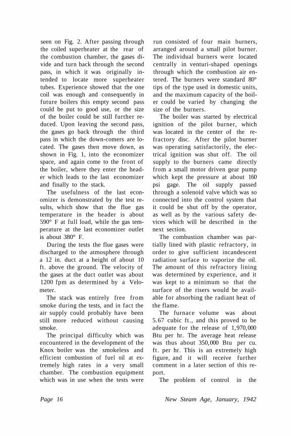
A Modern Steam Car
There are a large number of formersteam automobile drivers who wouldlike to own a modern steam car. Mostof them will wait some time. One ofthe few who have refused to wait isLeland Sprinkle, a ma themat i c i anwhose logical mind has led him intothe design of a steamer, and probablyinto no little trouble.
Utilizing available steam partswhere they were adequate, Sprinklebegan to assemble his steamer in No-vember, 1939. A Stanley engine, re-constructed by the use of piston valves,was mounted under a modern chasis.Instead of the awkward, heavy steamsupply pipe originally used oh the en-gine, three small pipes were fitted,providing a flexible and durable con-nection. The boiler is of the water-level, water tube type, built toSprinkle's own design. An indicator ofthe thermocouple type shows the wat-er level on the dashboard. Control ofwater level is by a mechanically oper-ated steam valve, controlling a steamfeed water pump. The burner, of theusual gun type, is controlled by a mer-cury switch, according to steam pres-sure fluctuations. The operating rangeis around 750 psi. The burner oper-
ates without smoke or noise on a fuelpressure of 50 psi, and ignition is bya dual system permitting independentuse of either coil and spark plug bysimply turning a switch on the instru-ment panel. The entire 12-volt elec-trical system is protected by three eas-ily accessible fuses.
A foot accelerator pedal of originaldesign returns to a closed position ofthe throttle by steam pressure ratherthan by a spring. This, and the hy-draulic braking system, provide simpleand safe control of the car by anynovice to steamers. A handsome mod-ern body of aluminum gives the car adistinguished appearance.
Gas Generators(Continued from. Page 4)
had begun to take effect in creatinginterest amongst fleet operators. Littleopportunity was ever presented forany actual military use of gas gener-ators, so rapid were the onslaughts ofmodern war. Civilian employment ofsubstitute fuels has been particularlyprevalent in Scandinavia, where char-coal is the principal fuel, and England,with its coal supply.
The Recent Past
Almost all of the European gener-ators in use were charcoal or wood-fired. All were of the down-draughtdesign, permitting loading of the mag-azine without extinguishing the fire.
A typical example is the Panhardgenerator, Fig. I, for use with char-coal. Operation may be describedbriefly as follows:
After lighting the fire through aport in the refractory (not shown)
Page 18 New Steam Age, January 1942
the blower is started, and the gener-ator is under slight pressure. Productsof combustion are exhausted to theatmosphere until the fire is well start-ed. A check valve on the air tube pre-vents backfiring. The engine is thenstarted on gasoline, and a two-wayvalve is manually changed to cut offthe gasoline carburetor and cut in thegas-air mixer. The starting blower isstopped, and the generator is underslight vacuum, depending on thespeed of the engine. Gas from the gen-erator is mixed with air at the engine,the proportion being about I to I. Notshown in Fig. 1 are the coolers andpurifiers, requiring as much space asthe generator itself, and the necessarymixing valve and controls. The puri-fiers are of several types, usually em-ployed in combination. Hemp, steelwool and other filtering materials areused to remove solid particles and toprecipitate condensables after the gashas passed through some form of cool-ing and expansion tubes. Oil andwater baths are used in final cleansing.Some of the products of combustionand distillation of the fuel are ex-tremely harmful if permitted to reachthe engine, particularly acetic acidwhen wood is burned.
The disadvantages of the use ofthis type of gas producer may be de-ducted from the above. The gas is notonly explosive but poisonous, consist-ing mainly of carbon monoxide andhydrogen. Fortunately the system isnormally under vacuum, but starting,and by-passing of gas when idling, in-volve certain risks. The gas cleaningdevices require daily attention, ashesmust He removed, and fuel is bulky.About 12 lbs. of charcoal are equiva-lent to a gallon of gasoline, so thatlarge storage capacity or frequent re-
plenishment of fuel must be resortedto. The major disadvantage, especial-ly to Americans, is the loss of powerresulting from the use of producergas. This often falls to 50 percent ofthe output with gasoline, and withrapidly varying load conditions, thequality of the gas fluctuates.
Most of these objections have beenovercome in modern practice, althoughthe cost of equipment has of course in-creased. The generator itself, how-ever, has not been changed in itsfundamentals.
(To be continued)
Knox Boiler(Continued from page 17)
ture was 380° F. It is estimated thatthe capacity given above might begreatly exceeded if the burner werepermitted to smoke, and if the feedwater pump could keep up with thedemands for water.
Hero II(Continued from page 6)
the companionway, spluttering thathe'd been kept out to olong. The own-er tossed a line around a pile, touchedthe reverse lever, and we were safeagainst the dock.
As I thanked the owner for this ex-cellent voyage, I noticed the steamgage, showing 75 lbs.
(A description of Hero's power plant willbe available in the next issue)
New Steam Age, January, 1942 Page 19
The Gas Turbine(Continued from page 10)
latter feature greatly jeopardizing thepossibility of achieving a dependableunit.
These prefatory remarks have in-dicated the limitations of previousmachines. The following section willbe devoted to a description of themodern combustion turbine, whichhas been made commercially practic-able only comparatively recently, and isbelieved to compensate adequately forthe deficiencies exhibited by earlier gasturbines. Much of the pioneer devel-opment work on the gas turbine to bedescribed has been conducted byBrown, Boveri & Co. in Switzerland.
Modern Combustion Turbine
The arrangement of a modern com-bustion gas turbine unit is depictedschematically in Fig. 2. Air from theatmosphere is compressed in a multi-stage axial flow compressor "B", driv-en by a reaction type gas turbine "A".Liquid or gaseous fuel injected at"C" is burned with part of the air dis-charged from the compressor; the re-maining, and greater, part flowsthrough the annular space "F" and,upon emerging, mixes with and coolsthe products of combustion to a suit-able turbine inlet temperature. Ex-pansion of this gas to atmosphere inthe turbine produces more power thanthat required to effect compression ofthe air, and the excess power is sup-plied to a generator "D". For startingpurposes a motor "E" is provided tobring the unit up to approximately 25percent of normal running speed, be-yond which the turbine is capable ofdriving the compressor unassisted.
(Modern commercial applications will bementioned in the next issue)
1200-lb Reheat(Continued from page 3)
oil burners to provide hot gases for thereheating elements, although built in-tegrally with the steam generatingboiler. This separation is required bythe special maneuvering and asternoperations of marine installations.
In turbines operating at standardpressures and temperatures (425 psi,740° F., 28. 5 in. vacuum) condensa-tion begins to take place about halfway through the turbine. The par-ticles retard the blades by impact, anderosion may take place. In the reheatcycle steam is removed from the highpressure turbine at a pressure slightlyhigher than that at which condensa-tion begins, reheated to its initial tem-perature, and expands in the low-pressure elements, condensing only inthe last few stages. Reheating there-fore decreases the number of stages inwhich moisture occurs, and the lossesdue to moisture.
Other gains due to reheating arefound in the properties of superheatedsteam to produce more work in theturbine than saturated steam. Withthe same initial steam conditions, a re-heat turbine, performing a larger por-tion of its work in the superheat re-gion, will be more efficient than a non-reheat turbine.
The above gains are effective with-in the turbine itself. The theoreticalefficiency, based on the Carnot cycle,is also increased by reheating, for theaverage temperature at which heat isadded is increased. 1
The main turbines consist of an allimpulse high pressure element, a com-
1 The detailed design of reheaters for this in-stallation, depending on many strictly marinerequirements, is omitted.
Page 20 New Steam Age, January, 1942
bined impulse and reaction intermedi-ate-pressure turbine, and an all reac-tion low-pressure turbine. Speeds are8010, 5035, and 4201 rpm, respective-
ly.Each of the two boilers contains
two separately fired furnaces. In onefurnace two oil burners supply theheat for the reheater and the primarysuperheater; the two burners in theother furnace control the boiler pres-sure and supply the heat needed toraise the temperature of the steam inthe secondary superheater. The reheat-er and the primary and secondarysuperheaters function as convectionunits and are protected from the radi-ant heat of the furnaces by water-cooled screen tubes. When reheat isnot required, the boiler furnace aloneis used.
Two main feed pumps, triplex-
plunger type, have variable stroke andare motor driven. The auxiliary feedpump, unusual for marine use, is avertical 16-stage centrifugal unit, driv-en at 6320 rpm by a single-wheel tur-bine.
For the 1200-lb ship, the fuel econ-omy will be about 0. 513 lb, comparedwith the average of 0. 595 lb for thetrials of the seven sister ships of the425-lb design. (12. 8 per cent reduc-tion) An increase of 9 per cent in theweight of machinery is expected. Nofair comparison of the costs of the twotypes can be made because only onehigh-pressure plant was installed, butit is estimated that under equal condi-tions, a 10 per cent increase could beexpected for the 1200-lb ship of thissize. Pending actual experience, acomparison of reliability, maintenancerequirements, and operation should bereserved.
New Steam Age, January, 1942 Page 21
The Steam Motor AssociationESTABLISHED 1941
To foster interest in the past achievements, present potentialities, and future develop-ment of steam as a motive power.
FRAMINGHAM, MASS., SEPT. 20, 1941 — The Steam Motor Association was form-ed at an informal meeting of amateurs of the steam car, following the annual meet ofthe Veteran Motor Car Club. A pleasant dinner was followed by impromptu stories fromthe 25 ladies and gentlemen present. Through the kind invitat ion of Mr. and Mrs.Hyde Ballard, to hold the next meeting at their home in Merion, Pa., a date was setfor October n. The meeting adjourned, and some of the members climbed into theirsteamers (there were four Stanleys of various vintages in the driveway of the restau-rant) and presumably reached home safely.
MERION, PA., OCT. n, 1941 — During the afternoon, several Stanleys brought pas-sengers to the Ballards' house, to be greeted by the sight of the host's collection of threesteamers. Everyone had a pleasant time examining these beaut i ful ly maintained veter-ans and riding in them, but the conversation centered on modern steam plants. A dinnerand meeting were held at a nearby hotel, and the Association now has a constitutionand an interesting program for fu ture meetings. Inquiries are invited from those inter-ested in establishing local groups in their own regions.
Byron Spence, President, Little Falls, N. Y. ; G. Stevenson, Vice President, Box 44,Newton, Mass.; Brooks Jones, Secretary, Glens Falls, N. Y. ; Deneale Hunter, Treasur-er, 20 Washington Place, Hackensack, N. J.
Regional Groups — New England: Russell J. Goodall, Vice President, Sanford, Me.Middle Atlantic: Hyde W. Ballard, Vice President, 227 Bowman Ave., Merion, Pa.

NEW
STEAM AGEThe Magazine of Modern Power
Contains exclusive information on the many
new developments taking place. You can't
afford to miss an issue. Subscribe, and give a
subscription to your friends for Christmas. An
unusually welcome gift.
• For designers, engineers, transportation
men, manufacturers.
• For students, mechanics, yachtsmen.
• For inventors, modelbuilders, steam car
experimentors, etc.
A two-dollar bill will bring you all the news
that may be printed on lightweight steam
power, for the first time between two covers.
TWO DOLLARS PER ANNUM IN U. S. A.
Published Quarterly By
NEW STEAM AGESTONINGTON, CONNECTICUT