Embed Size (px)
Citation preview

SEWERAGE SYSTEM
© The AUS-SPEC Joint Venture date: Jan 2002 Copying for on selling strictly prohibited AUS-SPEC-1\NSW-D12 Amended May 2009 Northern Rivers – Local Government
NEW SOUTH WALES
DEVELOPMENT DESIGN
SPECIFICATION
D12
SEWERAGE SYSTEM
VERSION 3.0

SEWERAGE SYSTEM
© The AUS-SPEC Joint Venture date: Jan 2002 Copying for on selling strictly prohibited AUS-SPEC-1\NSW-D12 Amended May 2009 Northern Rivers – Local Government
D12-2
SPECIFICATION D12 - SEWERAGE SYSTEM CLAUSE CONTENTS PAGE Amendment Record for this Specification Part.....................................................................................................4
GENERAL .............................................................................................................................5
D12.01 SCOPE ....................................................................................................................................................5 D12.02 OBJECTIVE.............................................................................................................................................5 D12.03 REFERENCE AND SOURCE DOCUMENTS .........................................................................................6
DESIGN CRITERIA...............................................................................................................8
D12.04 GENERAL................................................................................................................................................8 D12.05 DETERMINATION OF AREA TO BE SERVED ......................................................................................9 D12.06 DESIGN LOADING..................................................................................................................................9 D12.07 SEWER ALIGNMENT (WSA 02, 1, 4)...................................................................................................10 D12.08 MAINTENANCE STRUCTURES (WSA 02, 1, 6) ..................................................................................11 D12.09 (Deleted) ................................................................................................................................................12 D12.10 PIPELINE (WSA 02, 2) ..........................................................................................................................12 D12.11 JOINTS ..................................................................................................................................................13 D12.12 UNSTABLE AREAS..............................................................................................................................13
MATERIALS........................................................................................................................13
D12.13 UNPLASTICISED PVC (uPVC) GRAVITY PIPE...................................................................................13 D12.14 UNPLASTICISED & MODIFIED PVC (uPVC , PVC-M) PRESSURE PIPE..........................................14 D12.15 DUCTILE IRON (DI) PIPE AND FITTINGS...........................................................................................14 D12.16 (Deleted) ................................................................................................................................................14 D12.17 STEEL PIPE AND FITTINGS ................................................................................................................14 D12.18 POLYETHYLENE PIPE AND FITTINGS...............................................................................................15 D12.19 GLASS REINFORCED PLASTIC (GRP) PIPE AND FITTINGS ...........................................................15
SEWAGE PUMP STATIONS (SPS)....................................................................................15
D12.20 GENERAL..............................................................................................................................................15 D12.21 PUMPS, PIPEWORK, FITTINGS & VALVES .......................................................................................20 D12.22 ELECTRICAL.........................................................................................................................................21 D12.23 WATER SUPPLY...................................................................................................................................22 D12.24 ACCESS LADDERS..............................................................................................................................22 D12.25 TELEMETRY .........................................................................................................................................22 D12.26 OTHER APPURTENANCES .................................................................................................................22
RISING MAINS....................................................................................................................23

SEWERAGE SYSTEM
© The AUS-SPEC Joint Venture date: Jan 2002 Copying for on selling strictly prohibited AUS-SPEC-1\NSW-D12 Amended May 2009 Northern Rivers – Local Government
D12-3
D12.27 GENERAL..............................................................................................................................................23 D12.28 DESIGN PARAMETERS .......................................................................................................................23 D12.29 AUTOMATIC GAS RELEASE VALVES ................................................................................................24
TRUNK SEWERS................................................................................................................24
D12.30 DESIGN REQUIREMENT .....................................................................................................................24
DOCUMENTATION.............................................................................................................24
D12.31 RESERVED...........................................................................................................................................24 D12.32 RESERVED...........................................................................................................................................24 D12.33 RESERVED...........................................................................................................................................24 D12.34 RESERVED...........................................................................................................................................24 D12.35 RESERVED...........................................................................................................................................24 D12.36 RESERVED...........................................................................................................................................24

SEWERAGE SYSTEM
© The AUS-SPEC Joint Venture date: Jan 2002 Copying for on selling strictly prohibited AUS-SPEC-1\NSW-D12 Amended May 2009 Northern Rivers – Local Government
D12-4
Amendment Record for this Specification Part This specification is Council’s edition of the AUS-SPEC generic specification part and includes Council’s primary amendments.
Details are provided below outlining the clauses amended from the Council edition of this AUS-SPEC Specification part. The clause numbering and context of each clause are preserved. New clauses are added towards the rear of the specification part as special requirements clauses. Project specific additional script is shown in the specification as italic font.
The amendment code indicated below is ‘A’ for additional script, ‘M’ for modification to script, and ‘O’ for omission of script. An additional code ‘P’ is included when the amendment is project specific.
Amendment Sequence
No.
Key topic addressed in amendment
Clause No.
Amendment Code
Author Initials
Amendment Date
DRAFT Major revision for use in Northern Rivers Local Government Manuals
All AMOP GAK 13/3/2009
VERSION 3.0 Minor changes to DRAFT following consultation with Councils
Various AMO GAK 15/5/2009

SEWERAGE SYSTEM
© The AUS-SPEC Joint Venture date: Jan 2002 Copying for on selling strictly prohibited AUS-SPEC-1\NSW-D12 Amended May 2009 Northern Rivers – Local Government
D12-5
DEVELOPMENT DESIGN SPECIFICATION D12
SEWERAGE SYSTEM
GENERAL
D12.01 SCOPE
1. This Specification is for the design of sewerage systems for subdivisions and other development projects.
Design
2. The Specification contains procedures for the design of the following elements of the sewerage system:
(a) Gravity sewers including junctions, property connection sewers, maintenance holes and other associated sewerage structures.
(b) Common effluent sewers both gravity and pressurised.
(c) Vacuum sewer system.
(d) Pressure sewer systems.
(e) Rising mains.
(f) Pump stations.
Elements
3. The design of gravity sewer systems, pressure sewer systems, and their components shall comply with the Water Services Association of Australia’s publication WSA 02 – SEWERAGE CODE OF AUSTRALIA, WSA 04 – SEWAGE PUMPING STATION CODE OF AUSTRALIA, WSA 06 – VACUUM SEWERAGE CODE OF AUSTRALIA, and WSA 07 – PRESSURE SEWERAGE CODE OF AUSTRALIA unless specified otherwise herein and should be constructed in accordance with the DEVELOPMENT CONSTRUCTION SPECIFICATION C402 - SEWERAGE SYSTEM.
Compliance
4. A sewerage system designed in accordance with this specification is to provide sewerage connections for:
(a) All urban subdivision allotments and rural subdivision allotments to be serviced by reticulated sewer.
(b) Urban parks, reserves, public open spaces
(c) Public buildings, toilets and change rooms
The system shall include all connections, links to and upgrading capacity of the existing sewerage system and provide for extension for future upstream or adjacent development in the catchment.
D12.02 OBJECTIVE
1. The objective of the sewerage system is to transport sewage or effluent from domestic, commercial and industrial properties to the treatment plant in
Sewerage System
SEWERAGE SYSTEM
© The AUS-SPEC Joint Venture date: Jan 2002 Copying for on selling strictly prohibited AUS-SPEC-1\NSW-D12 Amended May 2009 Northern Rivers – Local Government
D12-6
accordance with all current relevant legislation. Consumer requirements shall be met by providing a sewer main and allowing an appropriate point of connection for each individual property.
D12.03 REFERENCE AND SOURCE DOCUMENTS
Whilst this document has been developed to provide consistency across the Northern Rivers Region including Ballina Shire Council, Byron Shire Council, Clarence Valley Council, Kyogle Council, Lismore City Council and Richmond Valley Council, individual Councils may still have current policies which may conflict with or contradict this specification. In cases of conflict or contradiction, unless otherwise specified, the provisions of the adopted individual Council policies will prevail until such time as they are superseded or revoked.
The Designer will consult with the individual Council/s and ensure any individual Council policies are taken into consideration. The Designer shall use the latest edition of any referenced document including amendments and supplements, unless specified otherwise in this Specification.
1. Documents referenced in this Specification are listed below whilst being cited in the text in the abbreviated form or code indicated. The Designer shall possess, or have access to, the documents required to comply with this Specification.
Documents
2. References to the Water Services Association of Australia’s publications are made where there are parallel sections or equivalent clauses to those in this Specification. Where not called up as part of this Specification, these references are identified by part and section numbers and enclosed in brackets thus (WSA Edition, Part, Section).
Sewerage Code
(a) Council Specifications
Northern Rivers Local Government Development and Design Manual
Northern Rivers Local Government Construction Manual
Northern Rivers Local Government Standard Drawings
(b) Australian Standards
References in this Specification or the Drawings to Australian Standards are noted by their prefix AS or AS/NZS. (WSA 02-2002, 0, III) AS 1102 - Graphical symbols for electrotechnical documentation
(various) AS 1214 - Hot dipped galvanised coatings on threaded fasteners (ISO
metric coarse thread series) AS/NZS 1260 - PVC pipes and fittings for drain, waste and vent applications AS 1281 - Cement mortar lining of steel pipes and fittings. AS 1444 - Wrought alloy steels – Standard, hardenability (H) series and
hardened and tempered to designated mechanical properties
AS/NZS 1477 - PVC pipes and fittings for pressure applications AS 1579 - Arc welded steel pipes and fittings for water and wastewater. AS/NZS 1594 - Hot rolled steel flat products AS 1631 - Cast grey and ductile iron non-pressure pipe and fittings AS 1646 - Elastomeric seals for waterworks purposes AS 1657 - Fixed Platforms, walkways, stairways and ladders – Design,
construction and installation AS 1741 - Vitrified clay pipes and fittings with flexible joints - Sewer
Australian Standards

SEWERAGE SYSTEM
© The AUS-SPEC Joint Venture date: Jan 2002 Copying for on selling strictly prohibited AUS-SPEC-1\NSW-D12 Amended May 2009 Northern Rivers – Local Government
D12-7
quality. AS 2129 - Flanges for pipes, valves and fittings AS 2200 - Design charts for water supply and sewerage AS/NZS 2280 - Ductile iron pressure pipes and fittings AS/NZS 2566.1 - Buried flexible pipelines – Structural design AS 2634 - Chemical plant equipment made from glass-fibre reinforced
plastics (GRP) based on thermosetting resins AS 2837 - Wrought alloy steels – Stainless steel bars and semi-finished
products AS 3500 - National Plumbing and Drainage Code AS 3518.1 - Acrylonitrile Butadienne Styrene (ABS) pipes and fittings for
pressure applications – Pipes AS 3518.2 - Acrylonitrile Butadienne Styrene (ABS) pipes and fittings for
pressure applications – Solvent cement fittings AS 3571 - Glass filament reinforced thermosetting plastics (GRP) pipes
- Polyester based - Water supply, sewerage and drainage applications
AS 3680 - Polyethylene sleevings for ductile iron pipelines. AS 3735 - Concrete structures for retaining liquid AS 3862 - External fusion-bonded epoxy coating for steel pipes AS 3996 - Metal access covers, road grates and frames. AS 4058 - Precast concrete pipes (pressure and non pressure) AS 4060 - Loads on buried vitrified clay pipes. AS 4087 - Metallic flanges for waterworks purposes AS 4100 - Steel structures AS/NZS 4129 - Fittings for polyethylene (PE) pipes for pressure applications. AS/NZS 4130 - Polyethylene (PE) pipes for pressure applications. AS/NZS 4131 - Polyethylene (PE) compounds for pressure pipes and
fittings. AS/NZS 4158 - Thermal-bonded polymeric coatings on valves and fittings for
water industry purposes AS/NZS 4321 - Fusion-bonded medium-density polyethylene coating and
lining for pipes and fittings AS/NZS 4765 (Int) Modified PVC (PVC–M) pipes for pressure applications HB48 - Steel structures design handbook.
Where not otherwise specified in this document, the Contractor shall use the latest Australian Standard available.
(c) Other
Institute of Public Works Engineering Australia (IPWEA) - Streets Opening Conference Information Bulletin on Codes
and Practices (Sections 3 and 4 detailing locations and depths of other services).
NSW Department of Commerce MEW E101 - Electrical Services Minimum Requirements
PWD - Safety Guidelines for fixed ladders, stairways, platforms and walkways for use in sewage treatment Works, pumping stations and maintenance holes.
WS-SPEC - Technical Requirements (TRs) and Strategic products Specifications (WSAA)
Water Services Association of Australia (WSAA) WSA 02 – SEWERAGE CODE OF AUSTRALIA WSA 04 – SEWAGE PUMPING STATION CODE OF AUSTRALIA WSA 06 – VACUUM SEWERAGE CODE OF AUSTRALIA WSA 07 – PRESSURE SEWERAGE CODE OF AUSTRALIA

SEWERAGE SYSTEM
© The AUS-SPEC Joint Venture date: Jan 2002 Copying for on selling strictly prohibited AUS-SPEC-1\NSW-D12 Amended May 2009 Northern Rivers – Local Government
D12-8
Building Codes Board of Australia - Building Code of Australia - PART E1, Fire Fighting
Equipment. European Standard. BS EN 1091 - Vacuum Sewerage Systems.
(d) Standard Drawings that apply to this section:
It is intended to develop a series of standard drawings for inclusion in the Northern Rivers Local Government Standard Drawings relating to water supply and sewerage systems. When these are developed, these drawings will be used in preference to other standard drawings. Where there is not a suitable standard drawing included in the Northern Rivers Local Government Standard Drawings, Council will consider use of other standard drawings.
Other standard drawings may be used, subject to assessment by the individual Council. Where proposed to use other standard drawings, such as those listed below, copies are to be provided with each set of design drawings to allow the use of the standard drawing to be assessed by the individual Council.
Tweed Shire Council Standard Drawings
IPWEA Standard Drawings
WSA Standard Drawings
Drawings
DESIGN CRITERIA
D12.04 GENERAL
1. Sewerage systems design criteria shall be in accordance with the Water Services Association of Australia Publications referenced in D12.03 unless specified otherwise herein.
Standard
2. The requirement of WSA 02, 1, 1.3.2, Planning responsibilities is to be ignored. Council will provide where available:
(a) Details of the existing sewerage system in the area and any significant proposed alterations
(b) Preferred connection point(s)
(c) Council’s Sewerage Strategy Study for the appropriate catchment
(d) Requirements for additional sewerage system capacity in the subdivision or development for future expansion
The Developer's Designers shall:
(a) From information provided by Council and the designer’s own investigations, evaluate the availability and capacity of the existing sewerage system to accept design flows from the development (and any required upstream areas)
(b) Determine if system upgrading downstream of the proposed development is required
(c) Design the subdivision/development sewerage system including the connections and links to the existing system; include provisions or extensions
Design Responsibility

SEWERAGE SYSTEM
© The AUS-SPEC Joint Venture date: Jan 2002 Copying for on selling strictly prohibited AUS-SPEC-1\NSW-D12 Amended May 2009 Northern Rivers – Local Government
D12-9
required to provide for future upstream or adjoining development in accordance with this specification; include necessary capacity upgrading of the existing downstream system.
(d) The design is to be consistent with the optimum design for the whole catchment including accommodation for any future extension of the system.
3. The Designer shall confirm the design criteria with Council and shall design a gravity pipeline distribution system with pump stations and rising mains, where necessary to comply with the requirements of this Specification, to transport fresh sewage, or common effluent, for treatment.
Conventional Gravity System, Pump Stations and Rising Mains
4. Alternative sewerage systems will only be considered after consultation with individual Councils.
Alternative Sewerage Systems
5. The Designer shall not provide for discharges from alternative sewerage systems to gravity sewers or conventional wastewater treatment plants without the concurrence of Council.
Discharges to Gravity Sewers
D12.05 DETERMINATION OF AREA TO BE SERVED
1. The area to be served shall be determined in accordance with WSA 02, Part 1 except that Council may require provision for an upstream sewer. In the design brief Council will indicate the level and size of existing or proposed pipe(s) as well as anticipated flows to be allowed for in the design.
Upstream Sewer
2. The depth of sewer shall be sufficient to allow a minimum of 90 per cent of each lot to be serviced.
Depth
3. All lots shall be able to be served by gravity sewers wherever possible. Provision of Sewerage
4. A Sewerage Management concept is to be submitted for approval with the development application. This concept should address (but not limited to) the following:
(a) Population – flow projections
(b) Staging of the development with flow capacities
(c) Septicity control management of each stage
(d) Pumping efficiency and costs of operation at each respective stage
(e) Minimum velocities in SRMs at each stage
(f) Overall operation costs at each stage (including servicing replacements)
(g) Comparative report on at least two total system options (if alternative to conventional gravity is proposed), with operational and maintenance costing for each stage for the consideration of the Council.
Sewerage Management
D12.06 DESIGN LOADING
1. Initial design may assume one Equivalent Tenement (ET), which equates to a standard single dwelling unit, is equal to 3.2 equivalent persons (EP), ie 1 ET = 3.2 EP. Storm allowance is based on the number of separate free standing
Storm Allowance

SEWERAGE SYSTEM
© The AUS-SPEC Joint Venture date: Jan 2002 Copying for on selling strictly prohibited AUS-SPEC-1\NSW-D12 Amended May 2009 Northern Rivers – Local Government
D12-10
structures connected or number of junction points, rather than ETs, but the storm allowance from mobile home parks and other medium density detached units should not exceed 10L/m2/day. If an applicant is considering using any other criteria it must be justified on an individual basis and approved by the respective Council
2. For all domestic and commercial flows, designers shall adopt an average dry weather flow (ADWF) contribution of 240L/EP/day. The Designer shall obtain the concurrence of Council for the flow to be used for the design of sewers serving industrial areas and developments not specifically listed in WSA 02 Part 1, section 2.3). If an applicant is considering using any other criteria it must be justified on an individual basis and approved by the respective Council
Flows
3. The design shall take account of AS 2200, AS/NZS 2566.1, AS 3500, AS 3735, and WSA02.
Design Codes
D12.07 SEWER ALIGNMENT (WSA 02, 1, 4)
1. Sewer mains are to be laid to each allotment. One junction is required per allotment. Exceptions will not be made for sewers passing through town houses or mobile home style developments.
Extent of Location
The guidelines of plan location of gravity sewer lines are offered below:
(a) On street frontages of allotments, sewer lines shall be located within 1 to 2 metres of the property boundary. Location of sewer lines in road reserves will be considered on merits on a case by case basis. Consideration must be given to any earthworks required for driveway construction. An easement over the sewer line of not less than 3.0 meters is to be provided.
(b) On side and rear boundaries of allotments, sewer lines shall be located 1 to 2 metres from the side boundary, with a minimum easement width of 1.5 times the sewer depth plus 0.5 metres, but not less than 3.0 metres.
Sewerage rising mains shall be located in road reserves where possible.
The impact of sewer trenches acting as subsoil drainage or reducing the bearing capacity of adjacent building wall or embankment foundations should be borne in mind by designers. Sewers shall not be laid in the bed or banks of unlined watercourses where the grade exceeds 1%.
All sewers in commercial and industrial areas shall be laid in Council controlled land, or contained in easements.
The consequences on the environment of any system component failure must be addressed.
Sewer Trenches
Commercial & Industrial areas
Environment
2. Where it is necessary for sewers to be located outside the development, the Designer shall obtain written approval from the affected property owner
Consent of Owner
3. Where sewers are proposed to be located within existing road reserves, the Designer shall check that the sewers do not conflict with other utility services and locate the sewers in accordance with established protocols. (WSA 02, 1, 4.4). Any requirements of the Road Authority and/or the Roads and Traffic Authority must be determined by the Designer and incorporated into the design.
Road Reserve
4. Sewers located on private property must be located in the centre of the easement, unless there are compelling reasons to the contrary. A Registered Surveyor shall survey easements and pipelines. (WSA 02, 1, 4.2.5).
Easement

SEWERAGE SYSTEM
© The AUS-SPEC Joint Venture date: Jan 2002 Copying for on selling strictly prohibited AUS-SPEC-1\NSW-D12 Amended May 2009 Northern Rivers – Local Government
D12-11
5. Where control of the trench width is practical or effective, the design may be based on wide trench condition. The Designer shall call up the need, in the Construction Specification, for the Contractor to supply special construction control with a method statement when there is economic justification to design to narrow trench condition.
Trench Width
D12.08 MAINTENANCE STRUCTURES (WSA 02, 1, 6)
1. (a) Maintenance structures comprise Maintenance Holes (MH’s), Maintenance Shafts (MS’s) and Terminal Maintenance Shafts (TMS’s). MH’s are Councils preferred maintenance structure. MS’s and TMS’s may be adopted subject to Council approval.
General
(b) Provision of MH’s, MS’s and TMS’s shall be in accordance with WSA 02, 1, Table 6.1. MS’s and TMS’s shall not be used as permanent ends to property connection sewers.
Application
(c) Maintenance structures shall generally be placed on gravity sewers as specified in WSA 02, 1, 6.3, except that the maximum spacing between adjacent maintenance structures shall be 90m.
Spacing
2. (a) All upstream ends of sewers shall terminate in a MH or TMS if the upstream end is more than 30m from the down stream maintenance hole.
Terminal MH or MS
(b) The designer should limit maximum MH depths to 5.0m. MS depths shall not exceed 4.0m.
Maximum Depth
3. Step irons are not required. Step Irons
4. The Designer shall provide for the venting of MH's which accept pumped discharges and appropriate odour control where required.
Venting
5. Connections to existing sewerage infrastructure shall require Council approval. Connections to Existing Systems
6. (a) All manhole lids and surrounds are be lightweight ductile iron of Australian manufacture and marked “San Sewer”, unless an alternate specification is requested by the Council. All metal access covers shall be manufactured in accordance with AS 3996. MH access openings shall have a minimum clear opening diameter of 600mm where les than 4m deep, and for maintenance holes deeper than 4m the standard clear opening 600mm x 900mm minimum. MS and TMS access covers shall have a minimum clear opening diameter of 225mm.
(b) Manhole covers should be suitable for use with non-proprietary lifting devices, and accessible using simple lifting hooks. The use of Gatic type lifting devices is not generally supported.
Access Covers
7. Precast manhole systems using reinforced or unreinforced concrete rubber ring jointed segments (Humes, Amatec or equivalent accepted) may be used. Standard manhole diameter shall be 1100mm. For maintenance holes deeper than 4m standard manhole diameter shall be 1500mm.
Manhole Standard Diameter
8. Minimum concrete strength for all cast insitu components of maintenance structures shall be 32MPa.
Concrete Strength
SEWERAGE SYSTEM
© The AUS-SPEC Joint Venture date: Jan 2002 Copying for on selling strictly prohibited AUS-SPEC-1\NSW-D12 Amended May 2009 Northern Rivers – Local Government
D12-12
9. MS’s or TMS’s having uPVC chambers shall be provided with 20MPa mass concrete encasing 150mm thick around the chamber. Concrete surfaces shall finish 100mm short of the connection pipe and riser shaft ends.
Concrete Encasement
10. The Designer shall take account of conditions limiting the use of maintenance shafts (WSA 02, 1, 6.7)
Conditions Limiting Use
D12.09 (Deleted)
D12.10 PIPELINE (WSA 02, 2)
1. Pipes and fittings for sewerage systems shall be of unplasticised PVC, modified PVC, ductile iron, steel, polyethylene, glass reinforced plastic or reinforced concrete with type CASL (calcareous aggregate with additional sacrificial cover). The material specifications for each pipe type are provided in Clauses D12.13 to D12.19 inclusive.
UPVC pipes for gravity sewers shall be RRJ class SN8 in 3m length.
Type
2. (a) Gravity pipelines for road crossings or where located under road pavements shall be series 1 white uPVC pressure pipe min class 12, or DI Epoxy Lined internally. House connections to these pipelines are not permitted. (b) Pressure pipelines for road crossings or where located under road pavements shall be DICL or uPVC class 16.
(c) Changes in pipe material shall only occur at MH's.
Road Crossings
3. Asbestos cement pipe and fittings shall not be used. Asbestos Cement
4. The physical and chemical nature of the soil and the nature of the likely trade wastes, e.g. industrial solvents, should be taken into consideration when selecting the type of piping.
5. Pipelines shall be buried. Above ground sewers may be designed in a gravity system only where other options are less practical. (WSA 02, 1, 4.6.3)
Buried Pipes
6. The Designer shall show on the Drawings the extent of external protection required to be undertaken by the Contractor. External protection shall be shown to comply with C402 – Sewerage System.
External Protection
7. Where sewer pipes or rising mains are to be located in close proximity to other services pipes or where there is the likelihood of the pipes not being recognised as sewerage pipes, the Designer shall provide for the pipes to be colour coded and shown on the Drawings accordingly.
Colour Coding
The following colour coding shall be used: Sewerage rising mains - cream or grey Effluent mains - purple
Pipe colours shall be displayed as follows: PVC pipe - pipe material to be coloured DICL pipes - polyethylene sleeving to be coloured PE pipes - pipe stripes to be coloured Other materials where the pipe or coating material cannot be coloured -
coloured polyethylene sleeving to be installed

SEWERAGE SYSTEM
© The AUS-SPEC Joint Venture date: Jan 2002 Copying for on selling strictly prohibited AUS-SPEC-1\NSW-D12 Amended May 2009 Northern Rivers – Local Government
D12-13
8. Piers for any above ground sewer pipeline shall be in accordance with WSA 02 Standard Drawing SEW-1404.
Piers
9. The pipeline alignment shall be such that no property connection sewer is to be more than 10m in length at its termination point inside the property boundary.
Property Connection
10. The Designer shall ensure that property connection point shall be not more than 1500mm in depth below the finished surface level.
Connection Depth
11. The Designer shall allow for adequate working area, waste removal and transport arrangements where scouring points or inspection pipe locations are nominated.
Special Allowances
12. The Designer shall design thrust blocks to resist maximum pressure of the pipe, not the estimated surge pressure.
Thrust Blocks
13. The Designer shall provide for surge control by specifying an appropriate rising main material and class selection. Minimum Class 12 pipes shall be used for sewage rising mains.
Surge Control Method
D12.11 JOINTS
1. Gravity sewers and rising mains shall generally be spigot and socket joints with rubber rings (elastomeric) complying with AS 1646, or butt welded in the case of polyethylene pipe.
Rubber Ring or Butt Welded
2. Flanged joints connecting pipes, fittings, valves and pumps shall comply with AS 4087.
Flanges
3. The concurrence of Council shall be obtained for the type of joint to be used (WSA 02, 3, 17).
D12.12 UNSTABLE AREAS
1. The pipe jointing system selected shall be capable of accepting ground movements, without impairing the water tightness of the joint. For areas with high ground strains a pipe jointing system using shorter effective length pipes and/or deep socket fittings shall be used.
In areas of known or suspected mass movement, subsidence or land slip, a geotechnical engineer’s investigation and report is required recommending design/construction techniques required to ensure that the expected working life of the system will not be compromised by geotechnical risks.
Geotechnical Issues, Pipe Jointing System
MATERIALS
D12.13 UNPLASTICISED PVC (uPVC) GRAVITY PIPE
1. Unplasticised PVC (uPVC) pipe shall be specified to be manufactured in accordance with AS/NZS 1260, designed in accordance with AS/NZS 2566.1 and with rubber ring (elastomeric) spigot and socket joints. (WSA 02, 2, 10). The pipe shall be not less than Class SN8.
Standard
2. The Designer shall ensure that PVC pipe is compatible with ductile iron (DI) pipe where necessary.
DI Compatible
3. Fittings for use with PVC pipe shall be elastomeric seal jointed. Fittings

SEWERAGE SYSTEM
© The AUS-SPEC Joint Venture date: Jan 2002 Copying for on selling strictly prohibited AUS-SPEC-1\NSW-D12 Amended May 2009 Northern Rivers – Local Government
D12-14
D12.14 UNPLASTICISED & MODIFIED PVC (uPVC , PVC-M) PRESSURE PIPE
1. Unplasticised PVC (uPVC) pressure pipe shall be specified to be manufactured in accordance with AS/NZS 1477 Series 2 and AS/NZS 4765, designed in accordance with AS/NZS 2566.1, and with rubber ring (elastomeric) spigot and socket joints. Modified PVC (PVC-M) pipes and fittings shall be specified to be manufactured in accordance with AS/NZS 4765 and have outside diameters from the Series 2 diameter range, designed in accordance with AS/NZS 2566.1, and with rubber ring (elastomeric) spigot and socket joints. (WSA 02, 2, 10). Oriented PVC (OPVC) pipes shall not be used.
Standard
2. The Designer shall ensure that PVC pressure pipe is compatible with ductile iron pipe where necessary.
DI Compatible
3. Fittings for use with PVC pressure pipe shall be DICL elastomeric seal jointed. Fittings
D12.15 DUCTILE IRON (DI) PIPE AND FITTINGS
1. Ductile iron pipes and fittings shall be specified to be manufactured and cement mortar lined in accordance with AS/NZS 2280 minimum Class PN20 for rubber ring (elastomeric) joints. Where pipes are flanged, Flanged Class shall be specified. (WSA 02, 2, 10)
Standard
2. The Designer shall specify cement mortar lining in accordance with AS 1281, or fusion-bonded medium density polyethylene to AS/NZS 4321 (for gravity mains). External protection shall be epoxy coating to AS 3862 where not otherwise specified as sleeved or wrapped, taking into account the type of corrosion protection required.
Corrosion Protection
3. Generally, pipe and fitting joints shall be specified to be spigot and socket type using a rubber ring (elastomeric) push in seal made of natural rubber, or ethylene propylene rubber with compounds complying with AS 1646. The seal shall be a single jointing component shaped to provide both groove lock and seal mechanisms.
Joints
4. Flanges shall be specified to be manufactured in accordance with AS 4087 Figure B5. Bolts, nuts and washers for flanged joints shall be stainless steel in accordance with AS 4087.
Flanges
D12.16 (Deleted)
D12.17 STEEL PIPE AND FITTINGS
1. Steel pipes and fittings shall be specified to be manufactured in accordance with AS 1579 and AS/NZS 1594 and designed to AS/NZS 2566.1. (WSA 02, 2, 10).
Standard
2. The Designer shall specify the jointing system where long-term corrosion resistance, ease of construction or special circumstances dictate the need. The pipe jointing shall be either:
Joints
(a) Rubber ring (elastomeric) jointed to conform to AS 1646, or
(b) Welded with butt welding or by using a welding collar with the application of a polyethylene heat shrunk sleeve over the weld, or wrapped, or
(c) Flanged to comply with AS 4087 table C. Bolts and nuts for flanged joints shall be stainless steel in accordance with AS 4087 and C402 – Sewerage System.
SEWERAGE SYSTEM
© The AUS-SPEC Joint Venture date: Jan 2002 Copying for on selling strictly prohibited AUS-SPEC-1\NSW-D12 Amended May 2009 Northern Rivers – Local Government
D12-15
3. Steel pipes and fittings shall be cement mortar lined in accordance with AS 1281 and coated externally with FBPE in accordance with AS 4321.
Corrosion protection
D12.18 POLYETHYLENE PIPE AND FITTINGS
1. Polyethylene pressure pipe shall be specified to be manufactured in accordance with AS/NZS 4130 and designed to AS/NZS 2566.1. (WSA 02, 2, 10)
Standard
2. Fittings shall comply with AS/NZS 4129 with compounds to AS/NZS 4131. Fittings
D12.19 GLASS REINFORCED PLASTIC (GRP) PIPE AND FITTINGS
1. Glass filament reinforced thermosetting plastics (GRP) pipes shall be specified to be manufactured to AS 3571 and designed to AS/NZS 2566.1. (WSA 02, 2, 10).
Standard
2. Fittings shall comply with AS 2634.
SEWAGE PUMP STATIONS (SPS)
D12.20 GENERAL
1. This section does not apply to pressure sewers. Any standard pump station drawings show typical layouts and details only. These drawings shall not be used by Designers as detailed design drawings. The Designer shall be wholly responsible for the design of the pump station and shall prepare a set of project specific detailed design drawings complete in all respects to allow construction and commissioning of the pump station.
Standard Drawings
2. The detailed design drawings shall be in accordance with the requirements of the applicable Codes of Practice, Australian Standards as well as the requirements of Statutory Authorities. The designer shall submit the complete set of detailed design drawings to Council for approval. Council will provide an SPS name and number to be displayed on the drawing title blocks. The construction certificate will only be released by Council on approval of the design submission.
Design Drawings
The design drawings shall clearly detail the following information (as a minimum requirement):
General a. Reference to applicable standard drawings, specifications and
Australian Standards.
Siteworks a. Landscaping details, reinstatement and surface finishing; b. Security fencing and gate (where required – Designer to check with
Council); c. Pump station, collector manhole and pipework setout details; d. Access driveway layout; e. Site drainage details; f. Water and power supply positions; g. Vent pipe and odour control equipment positions; h. Co-ordinate system and bench mark(s); i. Layout of overflow mitigation provisions.
Access driveway a. Horizontal and vertical alignment of access driveway;
SEWERAGE SYSTEM
© The AUS-SPEC Joint Venture date: Jan 2002 Copying for on selling strictly prohibited AUS-SPEC-1\NSW-D12 Amended May 2009 Northern Rivers – Local Government
D12-16
b. Pavement design details.
Pump well and valve pit general arrangement a. Pump, pipework and associated equipment details; b. Pump well and pump control levels; c. Access cover manufacturer, individual lid sizes and weights, cover
positions and lid configurations, opening directions and support beam positions;
d. Ladder position and details; e. Conduit, cable and cable support details; f. Ventilation and odour control details.
Concrete and reinforcing details a. Concrete layouts, levels and dimensions; b. Reinforcing steel details; c. Concrete grades and cover to reinforcing; d. Benching details; e. Corrosion protection coating details.
Pumps and switchboards a. Pump manufacturer, model, setout dimensions, clearances and
pump numbering; b. Pump performance details and curve; c. Guide rail details; d. Switchboard location and door opening orientation; e. Switchgear cabinet details; f. Pump schematics; g. Power circuit schematics; h. Telemetry control wiring details; i. Solid state starter layout; j. Electrical supply authority details.
Vent pipes and odour control system a. Position, details and dimensions of vent system; b. Manufacturer, model and complete details of odour control system.
3. (a) The Designer shall take into account access, site maintenance and restoration, easements, location of residential areas, power supply and working area when locating pump stations.
Location
(b) All pump stations are to be constructed within a separate Lot to be created in the plan of subdivision. The separate Lot is to be transferred to Council following registration of the plan of subdivision at no cost to Council.
(c) Lift stations may be located on lots within residential or commercial areas having direct frontage to a public road reserve not less than 10m wide.
(d) The distance to any residential or commercial lot boundary is to be maximised to prevent odour, noise and nuisance issues. Council strongly prefers to locate pump stations in public open space with at least a 50m buffer between the pump station, collector manhole or vent and adjacent property boundary. If this requirement cannot be met, the designer must justify the adequacy of the proposed buffer width with respect to the size of the pumping station, septic conditions of received flows, odour control measures and locality.
Buffers
4. (a) Where not provided as a Vacuum Sewerage System, the Designer shall provide for all pump stations to be of the single wet well submersible pump style with a minimum of two pumps in a duty/standby arrangement and with self contained freestanding switchboards suitable for external use.
Pump Station Type
(b) Council prefers the use of intermediate lift stations in place of pump stations Lift Stations

SEWERAGE SYSTEM
© The AUS-SPEC Joint Venture date: Jan 2002 Copying for on selling strictly prohibited AUS-SPEC-1\NSW-D12 Amended May 2009 Northern Rivers – Local Government
D12-17
where possible.
5. (a) The pump well shall be designed to accommodate peak wet weather flow for the ultimate catchment. The volume contained between the pump cut-in and cut-out levels shall be equivalent to 90 seconds pumping with the duty pump operating (WSA 04, Cl.4.5.2.3).
Well Capacity
(b) Pump wells shall be a maximum depth of 6 metres (top of slab to pump well floor). In special circumstances deeper pump wells may be approved by Council.
Well Depth
6. The Designer shall provide for the construction of the pump station and pump well after taking into consideration the ground and site conditions.
Site Conditions
7. Pump stations shall be of cast in-situ reinforced concrete construction. Preformed components or systems, for Pumping Stations may be used in lieu of in-situ construction provided:
Pump Station Construction
(a) The natural groundwater table is below the pump stop level (The Designer shall ensure selected components make a watertight system and have a satisfactory surface finish).
(b) Precast concrete wall units are to be manufactured to AS4058. The Designer shall take into account the cover requirements for reinforcing steel and cement types.
(c) Joints are flush with the internal concrete surfaces and joint restraint is in accordance with the manufacturer's requirements.
8. The site layout shall generally satisfy the following requirements: Site Layout
(a) The pump station shall be located in public open space or Council owned land, and shall not be closer than 50 metres to the nearest property boundary.
(b) The pump station site shall be a minimum of 225 square metres in area (excluding access).
(c) The pump station shall be oriented to discharge generally in the direction of the outgoing rising main. The maximum allowable change in rising main direction at the pump station site is 90 degrees.
(d) One collector manhole shall be provided between the incoming sewer(s) and the pump well. Only one inlet pipe into the pump well shall be provided. The minimum internal diameter of the collector manhole shall be 1500mm.
9. Pump stations shall be provided with an access driveway to satisfy the following requirements:
Access Driveways
(a) Driveways shall be geometrically designed to cater for the turning movements of a 4 tonne single rear axle truck. A three-point turning head shall be provided on all driveways. The turning head shall be located immediately adjacent to the pump station and be wholly contained within the pump station lot.
(b) Driveways less than 25m in length (measured from the kerb line/edge of seal of the public road to the start of the turning head) shall be constructed of reinforced concrete. Driveways longer than 25m may be constructed of reinforced concrete or asphaltic cement on suitable pavement..
SEWERAGE SYSTEM
© The AUS-SPEC Joint Venture date: Jan 2002 Copying for on selling strictly prohibited AUS-SPEC-1\NSW-D12 Amended May 2009 Northern Rivers – Local Government
D12-18
(c) Concrete driveways shall be designed in accordance with the Northern Rivers Local Government Design and Development Manual.
(d) Deleted
(e) Deleted
(f) The longitudinal grade of the access road shall not be steeper than 10%.
10. The Designer shall prepare a landscaping plan as part of the detailed design drawing set. The pump station site shall be landscaped by the Developer on completion of construction works in accordance with the approved landscaping plan.
Landscaping
11. Unless approved otherwise, access covers shall be of Havestock or Gatic (Icon) manufacture and shall satisfy the following requirements:
Access Covers
(a) Access covers shall be gas tight and finished flush with the concrete slab surface. Access covers shall be cast insitu with the concrete slab, recesses in the slab for grouting in frames are not permitted.
(b) Maximum mass of individual lids to be 56kg.
(c) Pump well access openings shall be sized to allow easy removal of the pumps and shall provide a minimum clear distance of 150mm between the outside of the pump and fixed surfaces during removal of pumps. If this requirement cannot be met, a larger pump well shall be provided. Valve pit access openings shall extend the full width of the valve pit and shall be sufficiently long to allow vertical removal of all valves.
(d) Two part or multi part access cover shall have lids of equal size.
(e) Multi part access cover support beams shall be removable and shall be provided with approved lifting lugs to allow easy removal when necessary.
(f) Cover removal directions shall be as shown on the standard drawings.
(g) The valve pit access covers and beam support shall be positioned to ensure that isolating valves can be operated with the support beam in place and the bypass pumping pipework can be easily connected to the bypass valve.
12. (a) Where a sewage pump station, collection manhole or rising main discharge manhole receives flows from a rising main having a detention time greater than four hours from the source (based on ADWF), then an odour management plan is to be submitted as part of the development approval process. An objective of this management plan should be to provide odour control facilities which have minimised ongoing operational costs, as opposed to minimised upfront capital costs.
Ventilation and Odour Control
(b) Vent pipes and odour control systems shall be specifically designed to suit the location of the pump station and the anticipated sewage septicity. Where necessary, specialist designed odour control systems shall be provided.
(c) Minimum odour control shall consist of a replaceable Council approved odour filter connected to a vent pipe as detailed in WSA 02 Standard Drawing SEW-1408 complete with a non-metallic ventilator at the end.
(d) The minimum height of the vent pipe shall be 7.5 metres above the SPS slab level and shall extend at least 1.0 metres above the tops of surrounding roofs

SEWERAGE SYSTEM
© The AUS-SPEC Joint Venture date: Jan 2002 Copying for on selling strictly prohibited AUS-SPEC-1\NSW-D12 Amended May 2009 Northern Rivers – Local Government
D12-19
within a radius of 50m. Vent pipe design shall also be subject to aesthetic considerations.
13. Where the pump station site is exposed to possible flooding by a 100 year flood event, the Designer shall consult with Council to establish a flood planning level and associated design requirements. Consideration must also be given for any requirements the Council may have with respect to sea level rises. Suitable flood mitigation measures will be site specific and could include:
Protection Against Flooding
(a) Elevating electrical cabinets to ensure that the cabinet footing level is 0.5 metres above the 100 year flood level. This is the preferred option where the difference in elevation between the top of the pump station slab and the top of the switchboard platform slab is less than 1.8m.
(b) Where an electrical building is required, the floor level is to be 0.5 metres above the 100 year flood level.
(c) Provision of a waterproof electrical cabinet to Council requirements.
14. The Designer shall provide for the design of pump wells to resist flotation both during the construction/installation stage and whilst operating under design flood conditions.
Protection Against Flotation
15. Package pump station units may be designed, with the prior concurrence of Council, where the area being serviced is small and/or their inclusion contributes to an overall lesser depth of excavation in the system.
Package Units
16. Council shall generally not accept the use of pumping stations servicing less than 50 lots or ET. Where a load of less than 50 ET is proposed, evidence must be provided to support a case for the proposed pumping station and approved by Council.
Minimum Lots Serviced by Pumping Station
17. The Designer shall provide for internal surfaces of wet wells, collection MH and SRM discharge MH to be prepared and coated with a corrosion resistant system approved by Council. All bolted connections within wet wells shall be stainless steel complying with AS 4087.
Surface Protection
18. At least 8 hours ADWF total storage shall be provided within the system. Overflow management shall not allow discharge to natural watercourse under any circumstances. Overflow management strategies shall be subject to Council approval and will be reviewed based on a risk management approach in accordance with Department of Environment and Climate Change guidelines. One of the following measures may be necessary:
Overflows
(a) Provision of an emergency generator to ensure uninterrupted pumping during power failures. Emergency generators are mandatory on regional or high risk sewage pump stations
Emergency Generator
(b) Provision of on-site overflow storage. If an overflow storage facility is required, provision shall be made to ensure automatic emptying of the storage facility once the overflow condition has passed.
Overflow Storage
19. (a) The Designer shall provide an alarm in the pumping system to indicate the occurrence of a sewage overflow. The overflow sensor shall be installed at the lowest point in the catchment (either at the pump station or at a sewer manhole if the manhole cover level is lower than the pump station cover level).
Alarms and Signals
(b) Where overflow storage has been provided, the overflow alarm level shall be set at the invert level of the overflow pipe. Where no overflow storage has been provided, the alarm level shall be set immediately below the cover level of the
SEWERAGE SYSTEM
© The AUS-SPEC Joint Venture date: Jan 2002 Copying for on selling strictly prohibited AUS-SPEC-1\NSW-D12 Amended May 2009 Northern Rivers – Local Government
D12-20
pump station or manhole.
20. Where gravity sewer manhole covers are below the level of the pump station slab level, bolt down covers shall be provided. A minimum difference in elevation of 1.3m is to be provided between adjacent house floor levels and the cover level of the bolted down manhole(s).
Bolted down manhole cover
21. Individual Councils may have preferred equipment details listed. Supply of alternative equipment shall be subject to Council approval. The Designer will be required to submit sufficient supporting documentation to enable Council to assess the suitability of the alternative equipment.
Preferred Equipment and Approved Equivalent
D12.21 PUMPS, PIPEWORK, FITTINGS & VALVES
1. Unless otherwise approved by Council, pumps shall be submersible by Flygt, KSB/Ajax, Mono/ABS or Grundfos/Sarlin three-phase power.
Pump Manufacturer
2. The Designer shall provide for pump stations to be fitted with identical suitably sized pumps, in conventional duty pump/standby pump arrangement.
Pump Configuration
3. Each pump shall be capable of passing solids of not less than 75mm diameter unless grinding equipment is incorporated.
Impeller Clearance
4. Each pump shall be capable of being removed with the aid of fixed guide rails. Pumps shall be supplied complete with lifting handles to allow easy removal from the bottom of pump wells with lifting equipment. Each pump shall be provided with lifting chain to Councils specifications and a davit arm with electric lifting equipment or alternate provision for removal of pumps, subject to Council approval.
Pump Removal
5. Pump sets are to be interchangeable within each pump station. Inter-changeable
6. Each pump shall have maximum speed of 1500 rpm. Pump Speed
7. Each pump shall have minimum capacity equal to PWWF at maximum head. Pump Capacity
8. Each pump should be designed for maximum 10 starts/hour. Starts per Hour
9. The Designer shall design structural steelwork in accordance with HB 48. Structural Steelwork
10. Pump numbering convention shall be such that when looking in the direction of flow in the rising main, pump 1 is situated on the LHS and pump 2 on the RHS. Brass numbering tags shall be provided.
Pump Numbering
11. The Developer shall supply Operation and Maintenance manuals in accordance with Appendix C of WSA101 (available free of charge on WSA website) and C402 - Sewerage System.
O&M Manuals
12. The actual duty point of each pump as recorded at commissioning shall be clearly recorded on the pump curves for inclusion in the Operation and Maintenance manuals.
Actual Duty Points
13. If the minimum equipment spacing and clearance requirements as detailed on S.D.222 cannot be satisfied, a larger pump well shall be provided.
Equipment Spacing
14. One pump (pump 2) shall be fitted with a flush valve installed in accordance with the manufacturer’s recommendations.
Flush Valve
15. Pressure pipes within the pump well, valve pit or cast into concrete shall be Pipe Type &
SEWERAGE SYSTEM
© The AUS-SPEC Joint Venture date: Jan 2002 Copying for on selling strictly prohibited AUS-SPEC-1\NSW-D12 Amended May 2009 Northern Rivers – Local Government
D12-21
Flanged Class K12 ductile iron. Buried pressure pipes shall be minimum class PN20 RRJ ductile iron or class 12 uPVC.
Class
16. All pipe and fitting flange drilling shall be to AS4087 figure B5. Bolts shall be SS316 and nuts and washers SS304. Anti-seize paste shall be applied to threads.
Flange Bolting
17. Pipes and fittings inside the pump well or valve pit shall be FBN coated internally and externally. Buried ductile iron pipes shall be wrapped in polyethylene sleeves.
Pipe Coating
18. Discharge pipes within the valve pit shall be provided with tapping points complete with ¾ inch BSP threaded stainless steel ball valves.
Pressure Tappings
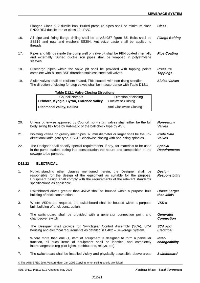
19. Sluice valves shall be resilient seated, FBN coated, with non-rising spindles. The direction of closing for stop valves shall be in accordance with Table D12.1
Table D12.1 Valve Closing Directions Council Name/s Direction of closing
Lismore, Kyogle, Byron, Clarence Valley Clockwise Closing
Richmond Valley, Ballina Anti-Clockwise Closing
Sluice Valves
20. Unless otherwise approved by Council, non-return valves shall either be the full body swing flex type by Val-matic or the ball check type by AVK.
Non-return Valves
21. Isolating valves on gravity inlet pipes 375mm diameter or larger shall be the uni-directional knife gate type, SS316, clockwise closing with non-rising spindles.
Knife Gate Valves
22. The Designer shall specify special requirements, if any, for materials to be used in the pump station, taking into consideration the nature and composition of the sewage to be pumped.
Special Requirements
D12.22 ELECTRICAL
1. Notwithstanding other clauses mentioned herein, the Designer shall be responsible for the design of the equipment as suitable for the purpose. Equipment design shall comply with the requirements of the relevant standards specifications as applicable.
Design Responsibility
2. Switchboard drives greater than 45kW shall be housed within a purpose built building of brick construction.
Drives Larger than 45kW
3. Where VSD’s are required, the switchboard shall be housed within a purpose built building of brick construction.
VSD’s
4. The switchboard shall be provided with a generator connection point and changeover switch
Generator Connection
5. The Designer shall provide for Switchgear Control Assembly (SCA), SCA housing and electrical requirements as detailed in C402 – Sewerage System.
SCA and Electrical
6. Where more than one (1) item of equipment is designed to form a particular function, all such items of equipment shall be identical and completely interchangeable (eg pilot lights, pushbuttons, relays, etc).
Inter-changeability
7. The switchboard shall be installed visibly and physically accessible above areas Switchboard

SEWERAGE SYSTEM
© The AUS-SPEC Joint Venture date: Jan 2002 Copying for on selling strictly prohibited AUS-SPEC-1\NSW-D12 Amended May 2009 Northern Rivers – Local Government
D12-22
at risk of flooding.
8. Ambient conditions shall be within the normally accepted limits of 0°C to 45°C. Ambient Conditions
9. The switchboard shall be connected to the local electricity supply system.
Nominal system parameters:
(a) 415 volt, 3-phase, 4-wire, 50 Hz, solidly earthed neutral system.
(b) Prospective Fault Current: As specified by the Local Supply Authority.
Connection to Local Supply
10. The works shall be designed in accordance with and subject to the provisions of MEW E101, except where modified by this Specification.
Standards
11. The pump station shall be designed for fully automatic operation in the unmanned condition.
Automatic Operation
12. The Developer shall provide a switchboard door having a separate 3 point stainless steel 316 locking system with a padlock for each of the main SCA and metering compartments. The developer shall purchase the padlock from the local electricity distributor for the metering compartment, and Council will provide a padlock to the main SCA compartment
Switchboard Locking System
D12.23 WATER SUPPLY
1. The Developer shall lodge an application with Council to have a metered water supply complete with appropriate backflow prevention installed by Council and shall pay all associated fees.
D12.24 ACCESS LADDERS
1. The pump well and the collector manhole shall be provided with a permanent stainless steel 316 vertical access ladder complete with extension styles.
Access Ladders
2. Ladders shall comply with AS 1657 and applicable Occupational Health and Safety legislation and should allow for easy rescue and confined space entry methods. A pivoting davit arm designed for fall arrest loadings shall be provided over access ladder.
Standard
3. Ladder cages shall not be used on ladders in pump station wet wells. Ladder Cages
D12.25 TELEMETRY
1. The Designer shall provide for telemetry requirements in accordance with individual Council requirements.
Schedule
2. The telemetry system is to be compatible with the existing system. Compatibility
D12.26 OTHER APPURTENANCES
1. The Designer shall provide for machinery lifting equipment including davit arm, guide rails, and pump chains. Safe lifting capacity of chains and davit arm shall be capable of lifting pumps such that they can be lifted onto the back of a standard medium rigid truck tray when parked on the access road. Chains shall be hot dip galvanised after fabrication. A separate davit arm or alternate fall arrest and rescue system mounting point is also to be provided for confined
Lifting Equipment

SEWERAGE SYSTEM
© The AUS-SPEC Joint Venture date: Jan 2002 Copying for on selling strictly prohibited AUS-SPEC-1\NSW-D12 Amended May 2009 Northern Rivers – Local Government
D12-23
space access.
2. The Designer shall provide pressure tapping for gauges for all valves, including isolation and non-return valves and as detailed in C402 – Sewerage System.
Gauges
RISING MAINS
D12.27 GENERAL
1. Rising mains may be of Ductile Iron, Hobas or UPVC AS 1477 Series 2 (min. Cl. 12) or heavier construction. Scours and air valves are required on sags and crests. Automatic gas release valves are required on sharp crests. Alternatively, risers may be considered if environmentally acceptable. Scour valves on sewer rising mains shall have gravity discharge to a nearby sewer manhole. If no gravity system exists a holding tank shall be provided, capacity of holding tank must be equivalent to volume of rising main discharging to scour valve.
Material
2. Discharge manholes are to be vented away from dwellings. Suitable ventilation and odour control facilities shall be provided if required. Odour control and staging shall be addressed. Rising main entry to the discharge manhole should preferably be from the floor bench invert level. Discharge manholes are to be coated with an epoxy paint system approved by Council.
Discharge Manhole
3. Minimum gravity sewer diameter at the point of rising main discharge shall be 75 millimetres more than the incoming pressure main, or 150mm, whichever is the greater.
Discharge Downstream Pipe Size
D12.28 DESIGN PARAMETERS
Minimum grades 1:500 uphill 1:300 downhill
Minimum velocity 0.6m/sec
Pref. Minimum velocity 1.0m/sec
Maximum velocity 3.0m/sec
Maximum sewage detention time in a pipe 4 hrs or provide oxygen injection
Minimum diameter 75mm unless grinder pumps approved
I

SEWERAGE SYSTEM
© The AUS-SPEC Joint Venture date: Jan 2002 Copying for on selling strictly prohibited AUS-SPEC-1\NSW-D12 Amended May 2009 Northern Rivers – Local Government
D12-24
D12.29 AUTOMATIC GAS RELEASE VALVES
Gas release valves shall be min 50mm nominal diameter Vent-O-Mat Model RGXv, or approved equivalent and shall have an isolation valve. The isolation valve shall be
(a) For 50mm dia: A fully SS ball valve
(b) For 80mm dia and larger: A sluice valve, fully coated with fusion bonded powder and shall have a vertical extension spindle and spindle cup extended through the valve chamber top slab.
Gas release valves
TRUNK SEWERS
D12.30 DESIGN REQUIREMENT
1. A sewer greater than 3m in depth or greater than 300 millimetres in diameter shall be designated as “trunk” sewers.
Designation
2. “Trunk” sewers shall be routed away from the built environment. Location
3. House connection shall not be permitted to “trunk” sewers. Side collection lines shall be installed.
Side Lines
4. Long “trunk” sewers shall be equipped with shaft venting. Ventilation
5. In general sewers deeper than 5m will not be permitted. Lifting stations to minimise depth are preferred.
Maximum depths
DOCUMENTATION
D12.31 RESERVED
D12.32 RESERVED
D12.33 RESERVED
D12.34 RESERVED
D12.35 RESERVED
D12.36 RESERVED