Embed Size (px)
Citation preview
ABSTRACT: The Leeville underground mine has been in operation since 2006 and currently produces 3,300 tons of ore per day with an average gold grade of 0.4 opt. The mine has a large horizontal extent of 2,500 feet by 500 feet and a vertical extent of 20 to 200 feet. High density of joints occur in the hosted rock. Based on the RMR rate and observation on the field, the ground condition of Leeville underground mine is poor to very poor. A heavy ground support is required for the mining operation in Leeville. The long hole stope mining method is currently used in Leeville underground. Because of the poor ground condition, the establishment of ground control monitoring system is the key of the successful operations in Leeville underground mine. The ground control monitoring system is composted of comprehensive instrument design and installations. Instruments include Multi-Point Bore-hole eXtensometers (MPBX) and Stretch Measurement to Assess Reinforcement Tension (SMART) ca-bles. The monitoring system covers the mining zones and infrastructure openings. After more than two years applications and measurements, many useful data are collected to use in the stope and infrastructure structure design. The system provides the information making engineer and operation teams to do their job more confident and efficiency. It proved that ground support principle in Leeville works. In mining zones, the changes of ground conditions in critical locations with mining process are completely recorded by the ground control monitoring system. The monitoring helps us to know the change trend of ground conditions as the mining operation continues. The information from monitoring system can help us to op-timize the support system and cut the support cost. In stope design, a large stope could be used in the ter-tiary stope mining, based on the results of ground control monitoring system and a series of numerical simulations. The width of stope can be widened at 30 ft to 40 ft. The large stope can help us improve the productivity and efficiency. It also dramatically could improve the safety in mining tertiary stope.The ground control monitoring system can timely response to any emergent hazard ground conditions, such as blast vibration and earthquake etc. 1 INTRODUCTION The Leeville Underground mine is located 27 miles northwest of the town of Carlin, Nevada in the Lynn Mining District, Eureka County, shown in Figure 1.
New progress in ground control monitoring system in Leeville underground mine Changshou Sun Newmont Mining Corp.
ROCKENG09: Proceedings of the 3rd CANUS Rock Mechanics Symposium, Toronto, May 2009 (Ed: M.Diederichs and G. Grasselli)
PAPER 4228 1
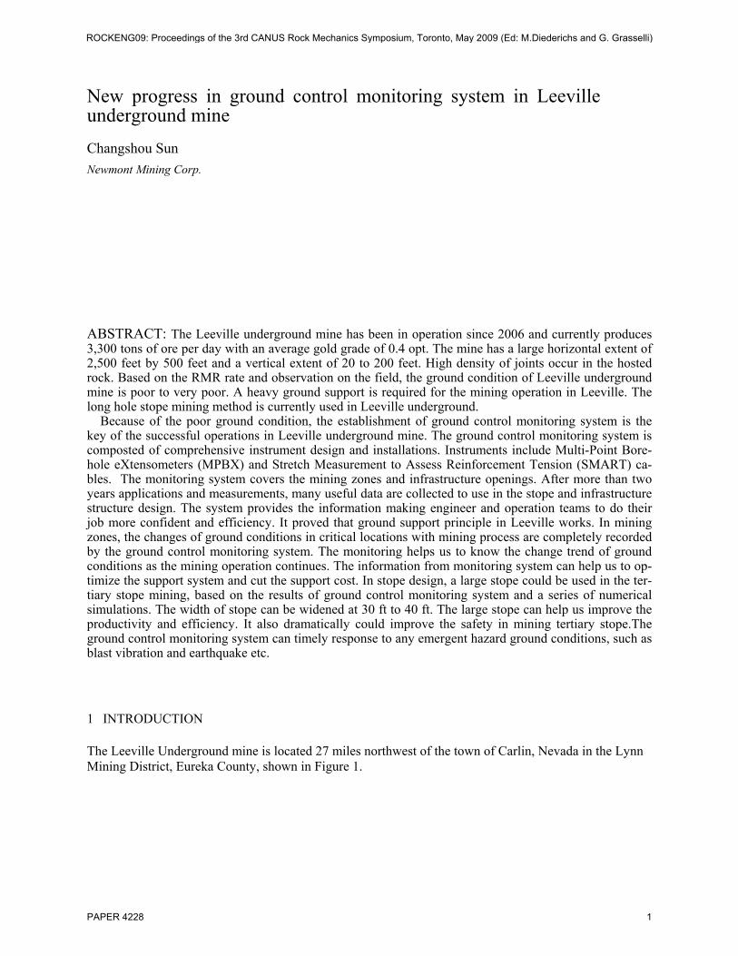
Figure 1. Location map for Leeville underground mine
The Leeville deposts are located at the northern of the Carlin Trend in the Tuscarora Mountains, which are also host to Newmont’s Blue Star/Geneses, Deep Post, Deep Star and Barrick’s Betze and Meikle mines. Leeville underground mine developed from 2002 and mining operation started from 2006. 3,300 tons/day ore production is currently mined.
2. GEOLOGY
Leeville deposits include three parts, West Leeville, Turf and Four Corner, shown in Figure 2. The West Leeville deposit is majority of the Leeville ore deposits. The majority of the Leeville ore deposits occur at depth of 1,400 to 1,600 ft and hosted by the flat lying, silty limestones of upper Silurian-Devonian Rob-erts Mountain formation. The Roberts Mountain Formation is subdivided into four lithological subunits, DSr1, DSr2, DSr3 and DSr4
The West Leeville ore occurs in two strata-bound zones near the transitional contacts between these units. The upper zone contains the bulk of the mineralization and occurs within the DSr2 and along the DSr2/DSr3. Lower zone mineralization occurs at the contact between the DSr3 and DSr4
ROCKENG09: Proceedings of the 3rd CANUS Rock Mechanics Symposium, Toronto, May 2009 (Ed: M.Diederichs and G. Grasselli)
PAPER 4228 2
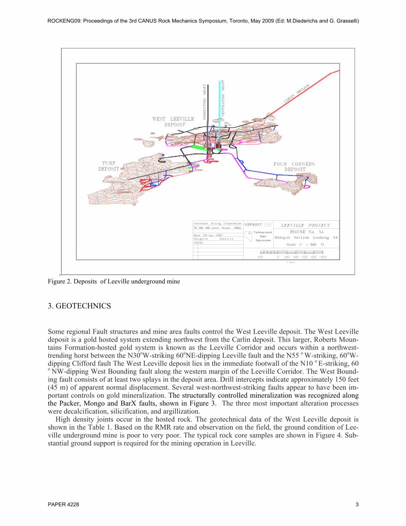
. Figure 2. Deposits of Leeville underground mine
3. GEOTECHNICS
Some regional Fault structures and mine area faults control the West Leeville deposit. The West Leeville deposit is a gold hosted system extending northwest from the Carlin deposit. This larger, Roberts Moun-tains Formation-hosted gold system is known as the Leeville Corridor and occurs within a northwest-trending horst between the N30oW-striking 60oNE-dipping Leeville fault and the N55 o W-striking, 60oW-dipping Clifford fault The West Leeville deposit lies in the immediate footwall of the N10 o E-striking, 60 o NW-dipping West Bounding fault along the western margin of the Leeville Corridor. The West Bound-ing fault consists of at least two splays in the deposit area. Drill intercepts indicate approximately 150 feet (45 m) of apparent normal displacement. Several west-northwest-striking faults appear to have been im-portant controls on gold mineralization. The structurally controlled mineralization was recognized along the Packer, Mongo and BarX faults, shown in Figure 3. The three most important alteration processes were decalcification, silicification, and argillization.
High density joints occur in the hosted rock. The geotechnical data of the West Leeville deposit is shown in the Table 1. Based on the RMR rate and observation on the field, the ground condition of Lee-ville underground mine is poor to very poor. The typical rock core samples are shown in Figure 4. Sub-stantial ground support is required for the mining operation in Leeville.
ROCKENG09: Proceedings of the 3rd CANUS Rock Mechanics Symposium, Toronto, May 2009 (Ed: M.Diederichs and G. Grasselli)
PAPER 4228 3
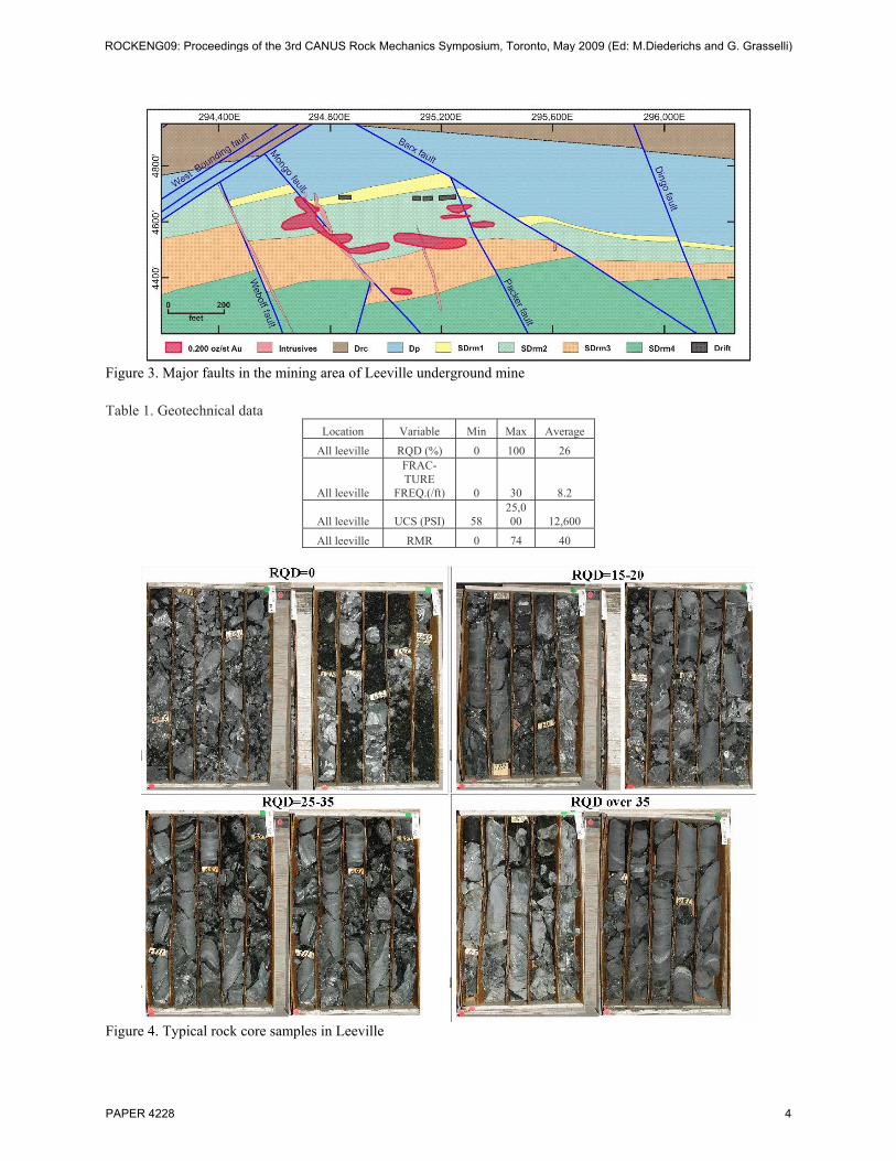
Figure 3. Major faults in the mining area of Leeville underground mine
Table 1. Geotechnical data
Location Variable Min Max Average
All leeville RQD (%) 0 100 26
All leeville
FRAC-TURE
FREQ.(/ft) 0 30 8.2
All leeville UCS (PSI) 58 25,000 12,600
All leeville RMR 0 74 40
Figure 4. Typical rock core samples in Leeville
ROCKENG09: Proceedings of the 3rd CANUS Rock Mechanics Symposium, Toronto, May 2009 (Ed: M.Diederichs and G. Grasselli)
PAPER 4228 4
4. MINING
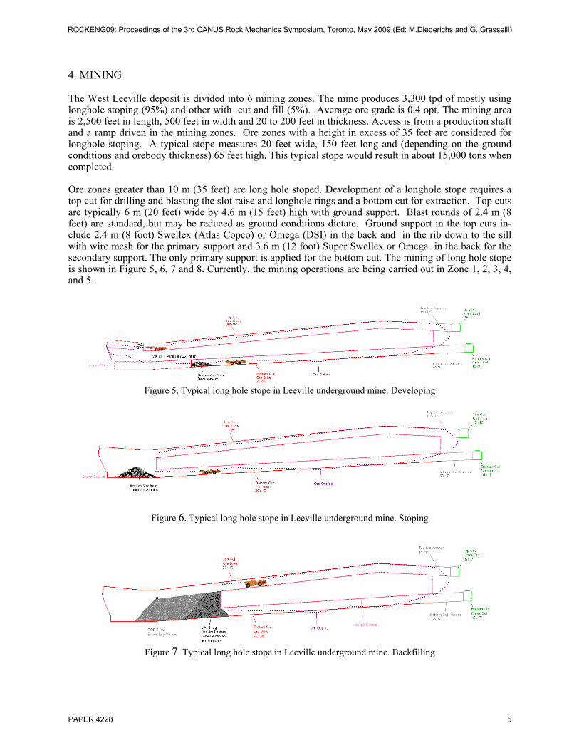
The West Leeville deposit is divided into 6 mining zones. The mine produces 3,300 tpd of mostly using longhole stoping (95%) and other with cut and fill (5%). Average ore grade is 0.4 opt. The mining area is 2,500 feet in length, 500 feet in width and 20 to 200 feet in thickness. Access is from a production shaft and a ramp driven in the mining zones. Ore zones with a height in excess of 35 feet are considered for longhole stoping. A typical stope measures 20 feet wide, 150 feet long and (depending on the ground conditions and orebody thickness) 65 feet high. This typical stope would result in about 15,000 tons when completed. Ore zones greater than 10 m (35 feet) are long hole stoped. Development of a longhole stope requires a top cut for drilling and blasting the slot raise and longhole rings and a bottom cut for extraction. Top cuts are typically 6 m (20 feet) wide by 4.6 m (15 feet) high with ground support. Blast rounds of 2.4 m (8 feet) are standard, but may be reduced as ground conditions dictate. Ground support in the top cuts in-clude 2.4 m (8 foot) Swellex (Atlas Copco) or Omega (DSI) in the back and in the rib down to the sill with wire mesh for the primary support and 3.6 m (12 foot) Super Swellex or Omega in the back for the secondary support. The only primary support is applied for the bottom cut. The mining of long hole stope is shown in Figure 5, 6, 7 and 8. Currently, the mining operations are being carried out in Zone 1, 2, 3, 4, and 5.
Figure 5. Typical long hole stope in Leeville underground mine. Developing
Figure 6. Typical long hole stope in Leeville underground mine. Stoping
Figure 7. Typical long hole stope in Leeville underground mine. Backfilling
ROCKENG09: Proceedings of the 3rd CANUS Rock Mechanics Symposium, Toronto, May 2009 (Ed: M.Diederichs and G. Grasselli)
PAPER 4228 5
Figure 8. Typical long hole stope in Leeville underground mine. Jamming
5. GROUND CONTROL PROBLEMS
Because of the poor ground condition, the establishment of ground control monitoring system is the key of the successful operations in Leeville underground mine. Many ground problems in de-signs and operations are needed to answer and resolve. They include:
• Are the large size infrastructure openings safely serving to mining operation for a long term mining operation? The large size infrastructure openings include underground shop, underground backfill plants, ore bin, waste bin, aggregate bin, underground shaft stations and conveyor drift. The spans of those openings are usually larger than 20 ft. the largest span is 45 ft. The ground support principle in Leeville is that a one half and one third of span rule is followed for the length of rock bolts (Hard Rock Miner’s Handbook and SME Mining Reference Handbook). The length of rock bolts should be at least one half of span if the span is less than 20 ft. The length of rock bolts should be at least one third of the span if the span is larger than 20 ft. This ground support should be verified by the ground control monitoring system.
• Are the critical mining accesses in mining zones stable during the period of mining op-eration? Those accesses include top cut and bottom cut accesses in Zone 1 and Zone 4. Some accesses locate in the middle of the ore body, such as 4460 access in Zone 1. The stability of those accesses is greatly concerned by engineers and operators.
• Are stope designs reasonable? The typical stope in Leeville is 20 ft wide, 30 to 90 ft high depending on the thickness of ore reserves, 100 to 200 ft long depending on the ground conditions. We need to prove that design being reasonable in the poor ground condition. Is it possible to apply a large stope, 30 ft to 40 ft in width, in the tertiary stope?
• Is ground support standard sufficient? The typical ground support in Leeville is to install 8 ft Swellex bolt with wire mesh and shotcrete for the primary support. The secondary support is to install the longer Super Swellex, or cable bolt depending on the span of the structures. We need to prove those support is sufficient or not.
6. GROUND CONTROL MONITORING SYSTEM
To solve problems mentioned above, a ground control monitoring system is designed. The ground control monitoring system is composted of comprehensive instrument design and instal-lations. Instruments include Stretch Measurement to Assess Reinforcement Tension Multi-Point Borehole eXtensometers (SMART MPBX), Stretch Measurement to Assess Reinforcement Ten-sion (SMART) cables, (manufactured by Mine Design Technologies, (MDT) Ontario Canada) and Extensometers, WR-FLEX (manufactured by Roctest, Quebec Canada). The monitoring system is a continuously recording system and covers the mining zones and infrastructure open-ings. Instrument design and installation are shown in Table 2.
ROCKENG09: Proceedings of the 3rd CANUS Rock Mechanics Symposium, Toronto, May 2009 (Ed: M.Diederichs and G. Grasselli)
PAPER 4228 6
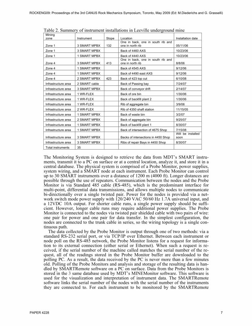
Table 2. Summery of instrument installations in Leeville underground mine Mining zone Instrument Stope Location Installation date
Zone 1 3 SMART MPBX 132 One in back, one in south rib and one in north rib 05/11/06
Zone 1 3 SMART MPBX Back of 4460 AXS 10/23/06 Zone 1 1 SMART MPBX Back of 4440 AXS 10/23/06
Zone 4 3 SMART MPBX 413 One in back, one in south rib and one in north rib 8/8/06
Zone 4 1 SMART MPBX Back of 4545 AXS 9/12/06 Zone 4 1 SMART MPBX Back of 4490 east AXS 9/12/06 Zone 4 2 SMART MPBX 423 Back of 423 top cut 6/10/08 Infrastructure area 2 SMART cable Back of Passing bay 7/24/07 Infrastructure area 3 SMART MPBX Back of conveyor drift 2/14/07 Infrastructure area 1 WR-FLEX Back of ore bin 1/30/06 Infrastructure area 1 WR-FLEX Back of backfill plant 2 1/30/06 Infrastructure area 1 WR-FLEX Rib of aggregate bin 3/9/06 Infrastructure area 2 WR-FLEX Rib of 4350 shaft station 11/15/05 Infrastructure area 1 SMART MPBX Back of waste bin 3/2/07 Infrastructure area 2 SMART MPBX Back of aggregate bin 9/25/07 Infrastructure area 1 SMART MPBX Back of backfill plant 1 8/30/07 Infrastructure area 1 SMART MPBX Back of intersection of 4675 Shop 7/15/08
Infrastructure area 3 SMART MPBX Backs of intersections in 4450 Shop Will be installed soon
Infrastructure area 3 SMART MPBX Ribs of repair Bays in 4450 Shop 8/30/07 Total instruments 35
The Monitoring System is designed to retrieve the data from MDT’s SMART instru-ments, transmit it to a PC on surface or at a central location, analyze it, and store it in a central database. The physical system is comprised of a Probe Monitor, power supplies, system wiring, and a SMART node at each instrument. Each Probe Monitor can control up to 30 SMART instruments over a distance of 1200 m (4000 ft). Longer distances are possible through the use of repeaters. Communication between the nodes and the Probe Monitor is via Standard 485 cable (RS-485), which is the predominant interface for multi-point, differential data transmissions, and allows multiple nodes to communicate bi-directionally over a single twisted pair. Power for the nodes is provided via a net-work switch mode power supply with 120/240 VAC 50/60 Hz 1.7A universal input, and a 12VDC 10A output. For shorter cable runs, a single power supply should be suffi-cient. However, longer cable runs may require additional power supplies. The Probe Monitor is connected to the nodes via twisted pair shielded cable with two pairs of wire: one pair for power and one pair for data transfer. In the simplest configuration, the nodes are connected to the trunk cable in series, so the wiring topology is a single con-tinuous path.
The data collected by the Probe Monitor is output through one of two methods: via a standard RS-232 serial port, or via TCP/IP over Ethernet. Between each instrument or node poll on the RS-485 network, the Probe Monitor listens for a request for informa-tion to its external connection (either serial or Ethernet). When such a request is re-ceived, if the serial number of the machine called matches the serial number of the re-quest, all of the readings stored in the Probe Monitor buffer are downloaded to the polling PC. As a result, the data received by the PC is never more than a few minutes old. Polling of the Probe Monitors and analysis and storage of the resulting data is han-dled by SMARTRemote software on a PC on surface. Data from the Probe Monitors is stored in the 3 same database used by MDT’s MINEMonitor software. This software is used for the visualization and interpretation of instrument data. The SMARTRemote software links the serial number of the nodes with the serial number of the instruments they are connected to. For each instrument to be monitored by the SMARTRemote
ROCKENG09: Proceedings of the 3rd CANUS Rock Mechanics Symposium, Toronto, May 2009 (Ed: M.Diederichs and G. Grasselli)
PAPER 4228 7
software, the user can set the reading frequency, which specifies the minimum interval (i.e. 5 minutes, 6 days, 3 weeks, etc.) between storing instrument readings in the data-base on the PC or network. The reading frequency for each instrument can be overrid-den by the Movement Alarm Threshold in SMARTRemote. This setting, expressed in units between 0 and 500, specifies the amount of reading change on any anchor node from the previous reading that will trigger automatic recording of data for an instru-ment. Thus, if movement occurs between scheduled readings, it will trigger an alarm and the reading will be stored in the database; the configured reading interval will then resume from that stored reading. This allows one to set up long intervals between read-ings to limit the amount of data in the database without missing any ground movements in the interim. An overall movement setting can also be specified. This alarm is trig-gered if any of the instrument anchors exceed a preset threshold.
7. NEW PROGRESS IN GROUND CONTROL MONITORING SYSTEM
Based on the data collected by ground control monitoring system, stability analyses for stope 132 in zone 1, 413 and 423 in Zone 4 and infrastructure areas are conducted. Some results were presented at SME annual conference such as the stability analysis for stope 132 and 413, (Sun, 2009). Here only some new results and finds are described. 7.1 Stability Analysis for Stope 423 Stope 423 is a large stope. The width of the stope is 35ft to 40 ft. The purpose of large stope is to mine the tertiary stope, cut the mining cost and improve the production effi-ciency. The large stope is composed of two regular stopes. The width of the large stope is 40 ft. the large stope is developed by a top cut and a bottom cut.
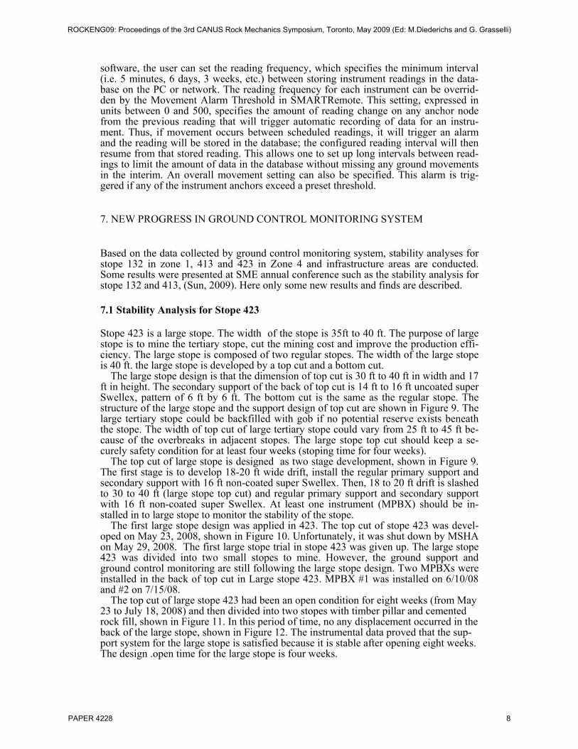
The large stope design is that the dimension of top cut is 30 ft to 40 ft in width and 17 ft in height. The secondary support of the back of top cut is 14 ft to 16 ft uncoated super Swellex, pattern of 6 ft by 6 ft. The bottom cut is the same as the regular stope. The structure of the large stope and the support design of top cut are shown in Figure 9. The large tertiary stope could be backfilled with gob if no potential reserve exists beneath the stope. The width of top cut of large tertiary stope could vary from 25 ft to 45 ft be-cause of the overbreaks in adjacent stopes. The large stope top cut should keep a se-curely safety condition for at least four weeks (stoping time for four weeks).
The top cut of large stope is designed as two stage development, shown in Figure 9. The first stage is to develop 18-20 ft wide drift, install the regular primary support and secondary support with 16 ft non-coated super Swellex. Then, 18 to 20 ft drift is slashed to 30 to 40 ft (large stope top cut) and regular primary support and secondary support with 16 ft non-coated super Swellex. At least one instrument (MPBX) should be in-stalled in to large stope to monitor the stability of the stope.
The first large stope design was applied in 423. The top cut of stope 423 was devel-oped on May 23, 2008, shown in Figure 10. Unfortunately, it was shut down by MSHA on May 29, 2008. The first large stope trial in stope 423 was given up. The large stope 423 was divided into two small stopes to mine. However, the ground support and ground control monitoring are still following the large stope design. Two MPBXs were installed in the back of top cut in Large stope 423. MPBX #1 was installed on 6/10/08 and #2 on 7/15/08.
The top cut of large stope 423 had been an open condition for eight weeks (from May 23 to July 18, 2008) and then divided into two stopes with timber pillar and cemented rock fill, shown in Figure 11. In this period of time, no any displacement occurred in the back of the large stope, shown in Figure 12. The instrumental data proved that the sup-port system for the large stope is satisfied because it is stable after opening eight weeks. The design .open time for the large stope is four weeks.
ROCKENG09: Proceedings of the 3rd CANUS Rock Mechanics Symposium, Toronto, May 2009 (Ed: M.Diederichs and G. Grasselli)
PAPER 4228 8
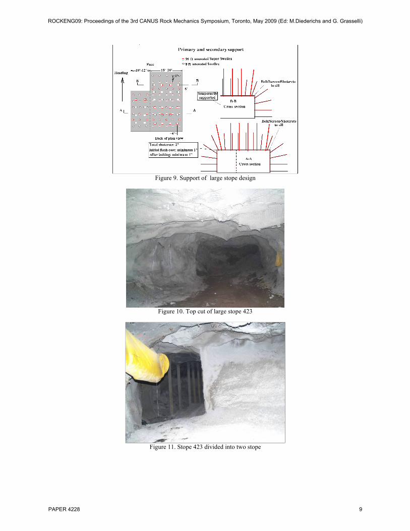
Figure 9. Support of large stope design
Figure 10. Top cut of large stope 423
Figure 11. Stope 423 divided into two stope
ROCKENG09: Proceedings of the 3rd CANUS Rock Mechanics Symposium, Toronto, May 2009 (Ed: M.Diederichs and G. Grasselli)
PAPER 4228 9
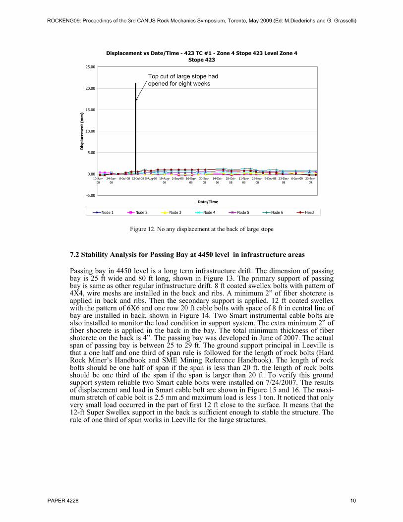
Displacement vs Date/Time - 423 TC #1 - Zone 4 Stope 423 Level Zone 4 Stope 423
-5.00
0.00
5.00
10.00
15.00
20.00
25.00
10-Jun-08
24-Jun-08
8-Jul-08 22-Jul-08 5-Aug-08 19-Aug-08
2-Sep-08 16-Sep-08
30-Sep-08
14-Oct-08
28-Oct-08
11-Nov-08
25-Nov-08
9-Dec-08 23-Dec-08
6-Jan-09 20-Jan-09
Date/Time
Dis
plac
emen
t (m
m)
Node 1 Node 2 Node 3 Node 4 Node 5 Node 6 Head
Top cut of large stope had opened for eight weeks
Figure 12. No any displacement at the back of large stope
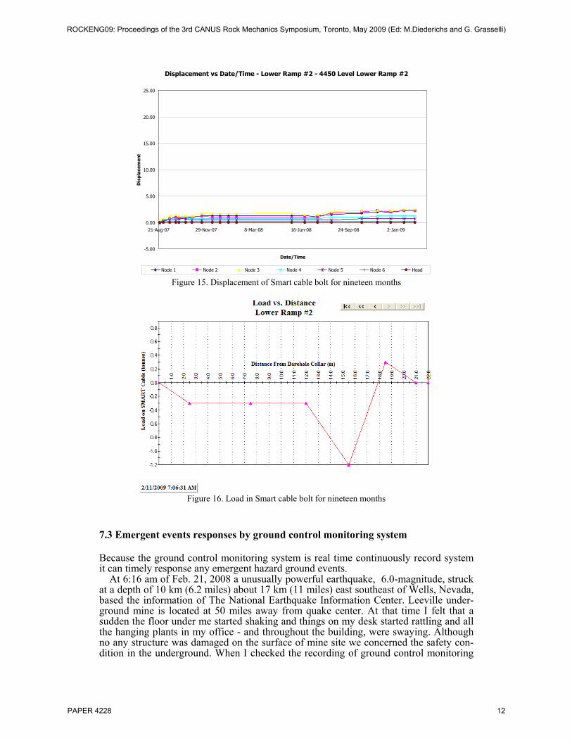
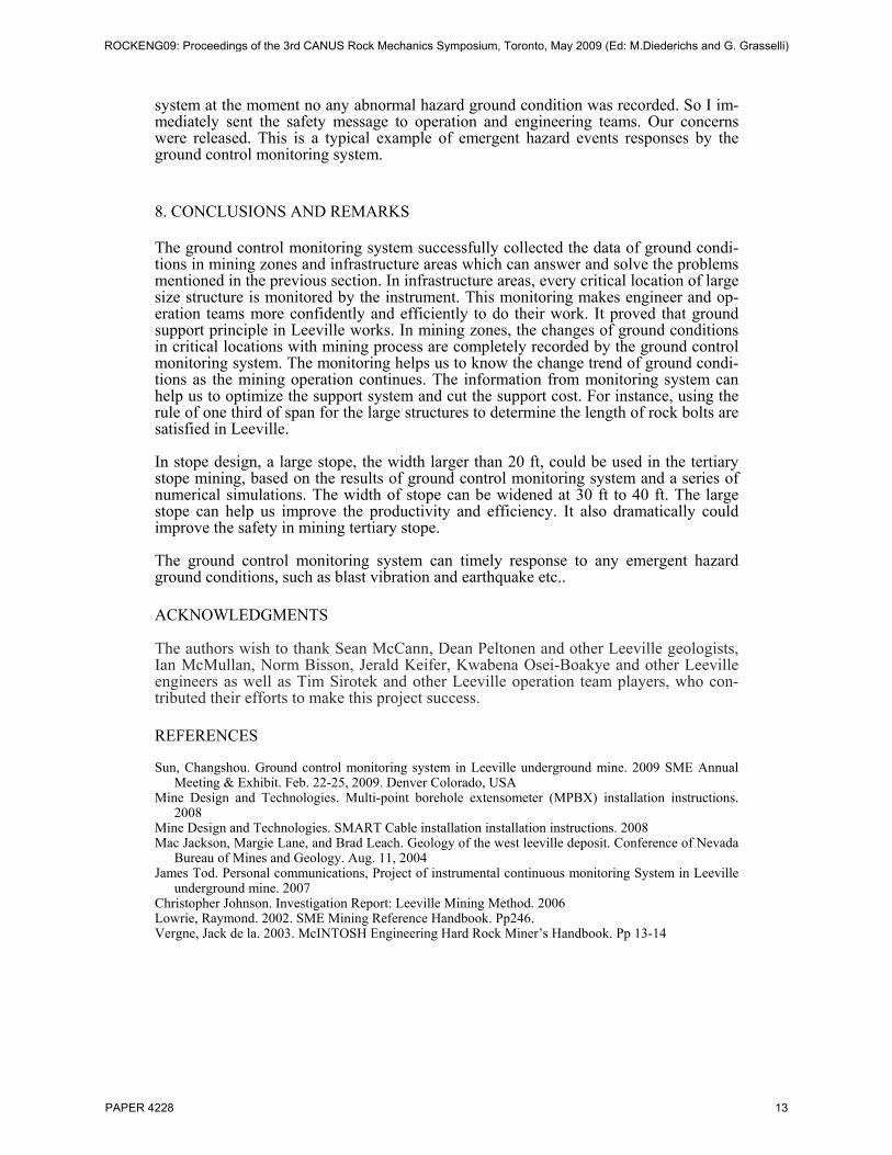
7.2 Stability Analysis for Passing Bay at 4450 level in infrastructure areas Passing bay in 4450 level is a long term infrastructure drift. The dimension of passing bay is 25 ft wide and 80 ft long, shown in Figure 13. The primary support of passing bay is same as other regular infrastructure drift. 8 ft coated swellex bolts with pattern of 4X4, wire meshs are installed in the back and ribs. A minimum 2” of fiber shotcrete is applied in back and ribs. Then the secondary support is applied. 12 ft coated swellex with the pattern of 6X6 and one row 20 ft cable bolts with space of 8 ft in central line of bay are installed in back, shown in Figure 14. Two Smart instrumental cable bolts are also installed to monitor the load condition in support system. The extra minimum 2” of fiber shocrete is applied in the back in the bay. The total minimum thickness of fiber shotcrete on the back is 4”. The passing bay was developed in June of 2007. The actual span of passing bay is between 25 to 29 ft. The ground support principal in Leeville is that a one half and one third of span rule is followed for the length of rock bolts (Hard Rock Miner’s Handbook and SME Mining Reference Handbook). The length of rock bolts should be one half of span if the span is less than 20 ft. the length of rock bolts should be one third of the span if the span is larger than 20 ft. To verify this ground support system reliable two Smart cable bolts were installed on 7/24/2007. The results of displacement and load in Smart cable bolt are shown in Figure 15 and 16. The maxi-mum stretch of cable bolt is 2.5 mm and maximum load is less 1 ton. It noticed that only very small load occurred in the part of first 12 ft close to the surface. It means that the 12-ft Super Swellex support in the back is sufficient enough to stable the structure. The rule of one third of span works in Leeville for the large structures.
ROCKENG09: Proceedings of the 3rd CANUS Rock Mechanics Symposium, Toronto, May 2009 (Ed: M.Diederichs and G. Grasselli)
PAPER 4228 10
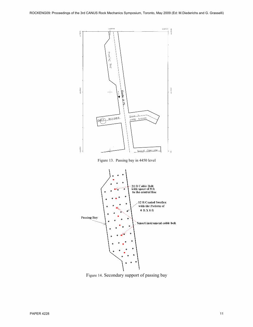
Figure 13. Passing bay in 4450 level
Figure 14. Secondary support of passing bay
ROCKENG09: Proceedings of the 3rd CANUS Rock Mechanics Symposium, Toronto, May 2009 (Ed: M.Diederichs and G. Grasselli)
PAPER 4228 11
Displacement vs Date/Time - Lower Ramp #2 - 4450 Level Lower Ramp #2
-5.00
0.00
5.00
10.00
15.00
20.00
25.00
21-Aug-07 29-Nov-07 8-Mar-08 16-Jun-08 24-Sep-08 2-Jan-09
Date/Time
Dis
plac
emen
t
Node 1 Node 2 Node 3 Node 4 Node 5 Node 6 Head Figure 15. Displacement of Smart cable bolt for nineteen months
Figure 16. Load in Smart cable bolt for nineteen months
7.3 Emergent events responses by ground control monitoring system Because the ground control monitoring system is real time continuously record system it can timely response any emergent hazard ground events.
At 6:16 am of Feb. 21, 2008 a unusually powerful earthquake, 6.0-magnitude, struck at a depth of 10 km (6.2 miles) about 17 km (11 miles) east southeast of Wells, Nevada, based the information of The National Earthquake Information Center. Leeville under-ground mine is located at 50 miles away from quake center. At that time I felt that a sudden the floor under me started shaking and things on my desk started rattling and all the hanging plants in my office - and throughout the building, were swaying. Although no any structure was damaged on the surface of mine site we concerned the safety con-dition in the underground. When I checked the recording of ground control monitoring
ROCKENG09: Proceedings of the 3rd CANUS Rock Mechanics Symposium, Toronto, May 2009 (Ed: M.Diederichs and G. Grasselli)
PAPER 4228 12
system at the moment no any abnormal hazard ground condition was recorded. So I im-mediately sent the safety message to operation and engineering teams. Our concerns were released. This is a typical example of emergent hazard events responses by the ground control monitoring system. 8. CONCLUSIONS AND REMARKS The ground control monitoring system successfully collected the data of ground condi-tions in mining zones and infrastructure areas which can answer and solve the problems mentioned in the previous section. In infrastructure areas, every critical location of large size structure is monitored by the instrument. This monitoring makes engineer and op-eration teams more confidently and efficiently to do their work. It proved that ground support principle in Leeville works. In mining zones, the changes of ground conditions in critical locations with mining process are completely recorded by the ground control monitoring system. The monitoring helps us to know the change trend of ground condi-tions as the mining operation continues. The information from monitoring system can help us to optimize the support system and cut the support cost. For instance, using the rule of one third of span for the large structures to determine the length of rock bolts are satisfied in Leeville. In stope design, a large stope, the width larger than 20 ft, could be used in the tertiary stope mining, based on the results of ground control monitoring system and a series of numerical simulations. The width of stope can be widened at 30 ft to 40 ft. The large stope can help us improve the productivity and efficiency. It also dramatically could improve the safety in mining tertiary stope. The ground control monitoring system can timely response to any emergent hazard ground conditions, such as blast vibration and earthquake etc.. ACKNOWLEDGMENTS The authors wish to thank Sean McCann, Dean Peltonen and other Leeville geologists, Ian McMullan, Norm Bisson, Jerald Keifer, Kwabena Osei-Boakye and other Leeville engineers as well as Tim Sirotek and other Leeville operation team players, who con-tributed their efforts to make this project success. REFERENCES Sun, Changshou. Ground control monitoring system in Leeville underground mine. 2009 SME Annual
Meeting & Exhibit. Feb. 22-25, 2009. Denver Colorado, USA Mine Design and Technologies. Multi-point borehole extensometer (MPBX) installation instructions.
2008 Mine Design and Technologies. SMART Cable installation installation instructions. 2008 Mac Jackson, Margie Lane, and Brad Leach. Geology of the west leeville deposit. Conference of Nevada
Bureau of Mines and Geology. Aug. 11, 2004 James Tod. Personal communications, Project of instrumental continuous monitoring System in Leeville
underground mine. 2007 Christopher Johnson. Investigation Report: Leeville Mining Method. 2006 Lowrie, Raymond. 2002. SME Mining Reference Handbook. Pp246. Vergne, Jack de la. 2003. McINTOSH Engineering Hard Rock Miner’s Handbook. Pp 13-14
ROCKENG09: Proceedings of the 3rd CANUS Rock Mechanics Symposium, Toronto, May 2009 (Ed: M.Diederichs and G. Grasselli)
PAPER 4228 13

![LA 1 Phase 2 Leeville to Golden Meado Design and... · –Estimated cost: $30M-$50M 8 . LA 1 Phase 2 Phase 2 • Phase 2D – Northern Segment ... Girder Spans îð_WXWX Xo }vP ]o](https://img.pdfslide.us/doc/110x75/5ca4f0a388c993101e8b5589/la-1-phase-2-leeville-to-golden-design-and-estimated-cost-30m-50m-8.jpg)