Embed Size (px)
Citation preview
373
Motion sensors for 1 circuitideal for passage, outdoor and humid areas(p. 377)
NEW products 2014
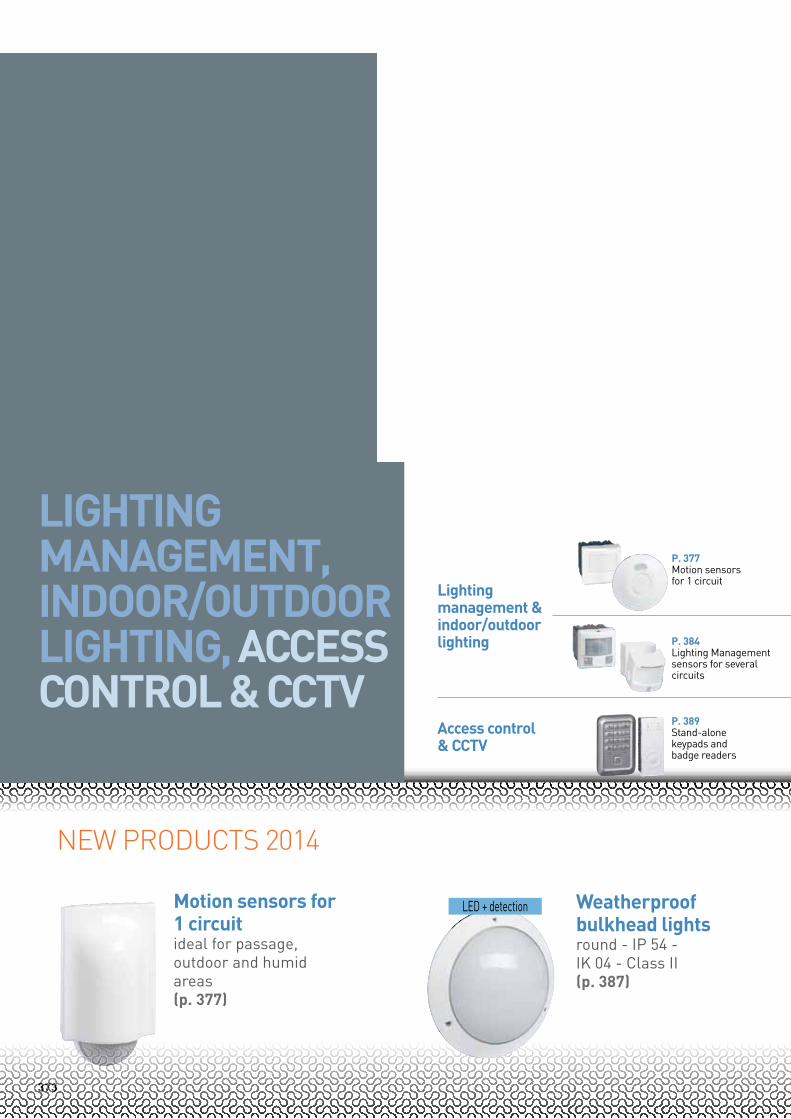
Lighting management & indoor/outdoor lighting
Access control & CCTV
P. 377Motion sensors for 1 circuit
P. 384Lighting Management sensors for several circuits
P. 389Stand-alone keypads and badge readers
LED + detection Weatherproof bulkhead lightsround - IP 54 - IK 04 - Class II(p. 387)
LighTing MAnAgeMenT, inDOOR/OUTDOORLighTing, ACCess COnTROL & CCTV
374
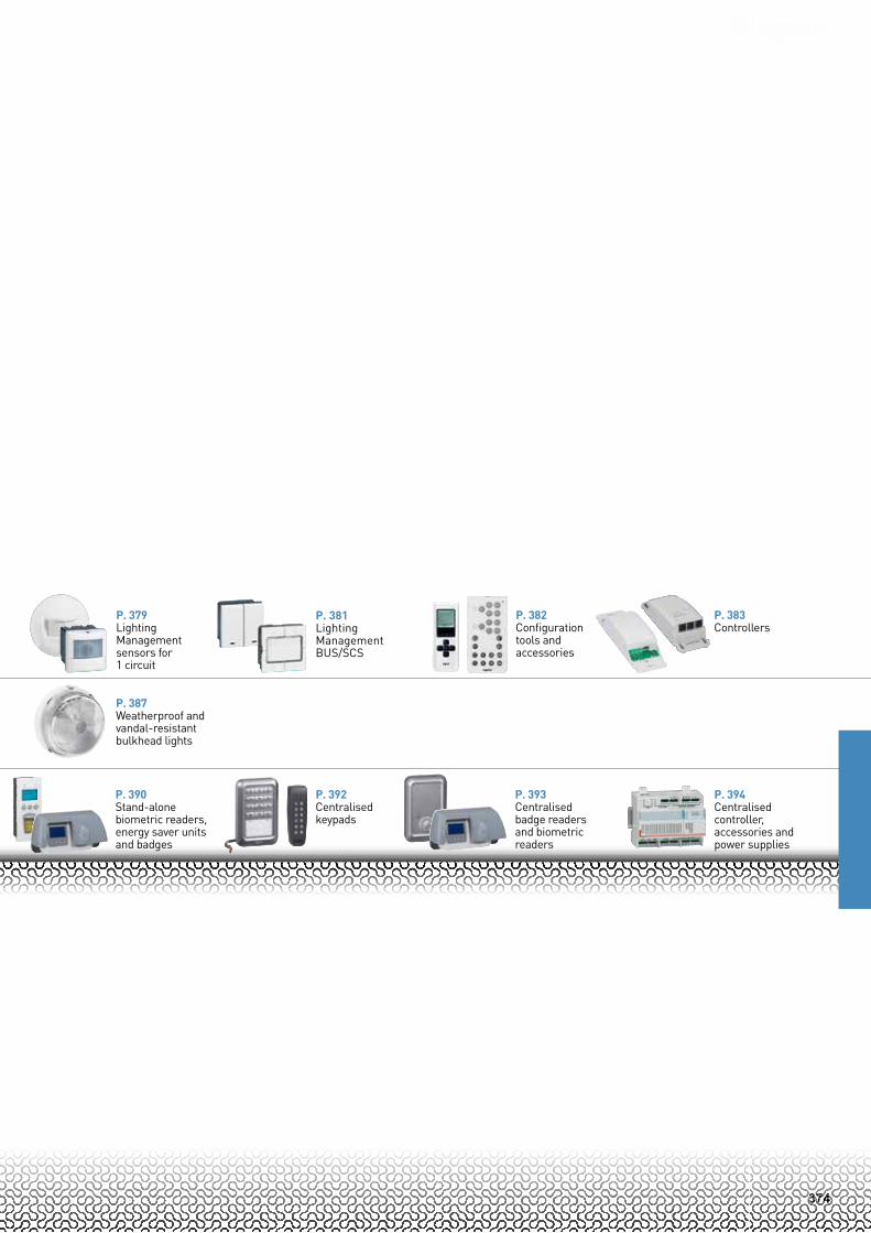
P. 379Lighting Management sensors for 1 circuit
P. 381Lighting Management BUS/SCS
P. 387Weatherproof and vandal-resistant bulkhead lights
P. 382Configuration tools and accessories
P. 383Controllers
P. 394Centralised controller, accessories and power supplies
P. 390Stand-alone biometric readers, energy saver units and badges
P. 392Centralised keypads
P. 393Centralised badge readers and biometric readers

375
Motion and Lighting Management sensors for 1 circuitselection chart
Lighting management SenSORSaReaS with natuRaL Light Automatic On-Off / Checking permanently the presence and day-light level
wORking aReaS
individual office / small room Ø 8 m
0 488 00 / 0 488 04(3)8 m
0 489 14
8 m
With neutral: 5 740 49Without neutral: 5 740 31
Open space / classroom / meeting room Ø 8 m
0 488 06(1) / 0 488 098 m
0 489 16(3)
8 m
With neutral: 5 740 49Without neutral: 5 740 31
PaSSage aReaS
hall / lobbyStairways / hallways Ø 8 m
0 488 07(1) / 0 488 08(1)
20 m
0 489 17(3)
8 m
With neutral: 5 740 47Without neutral: 5 740 34(4)
hallwaysVery long areas 2 x 12 m
0 488 17(1)20 m
0 489 17(3)
8 m
With neutral: 5 740 47Without neutral: 5 740 34(4)
high ceiling areas (gymnasium,storage areas...)
0 489 32 (Flush-mounting)
Ø 25 m
10 mfixingheight
20 m
270°
0 489 33
Restrooms, bathroomsDressing room Ø 8 m
0 488 04(3)8 m
0 489 16(3)
8 m
With neutral: 5 740 47Without neutral: 5 740 34(4)
OutSiDe & humiD aReaS
internal/outside parking lotinternal entrance areas
Ø 8 m0 489 32
20 m
270°
0 489 33 Directional head
20 m
270°
0 489 33 Directional head
iP 55
iP 55
PaSSage aReaS
hall / lobbyStairways / hallwaysStorage areas / technical areas
Ø 8 m
0 488 03(1)8 m
0 489 11
8 m
With neutral: 5 740 47Without neutral: 5 740 34(4)
OutDOOR anD humiD aReaS
internal/external parking lotinternal entrance areas Ø 8 m
0 697 40 / 0 697 80
8 m
0 489 31 Fixed head
8 m
0 697 40 Directional head
0° / 90°
mOtiOn SenSORS
aReaS withOut natuRaL Light
inStaLLatiOn
Ceiling
wall
Surface-mounting(2) Flush-mounting(1)
arteor
1: Surface-mounting box option - 2: angle mounting option - 3: 1 lighting output + 1 fan output - 4: Retro-fit dedicated solution
iP 55
376
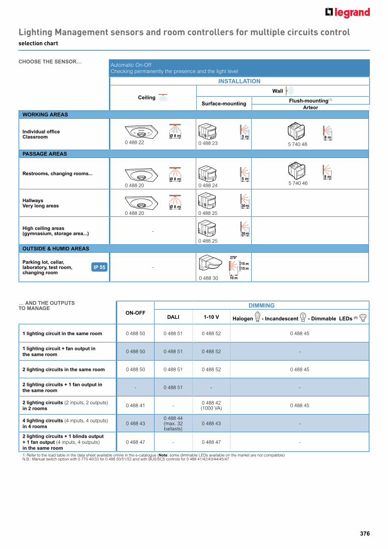
Lighting Management sensors and room controllers for multiple circuits controlselection chart
wORking aReaS
individual officeClassroom Ø 8 m
0 488 225 m
0 488 238 m
5 740 48
PaSSage aReaS
Restrooms, changing rooms...Ø 8 m
0 488 20
5 m
0 488 24
8 m
5 740 46
hallwaysVery long areas Ø 8 m
0 488 20
30 m
0 488 25
high ceiling areas (gymnasium, storage area...) - 30 m
0 488 25
OutSiDe & humiD aReaS
Parking lot, cellar, laboratory, test room,changing room
-
10 m
15 m15 m
270°
0 488 30
On-OFFDimming
DaLi 1-10 V halogen - incandescent - Dimmable LeDs (1)
1 lighting circuit in the same room 0 488 50 0 488 51 0 488 52 0 488 45
1 lighting circuit + fan output in the same room
0 488 50 0 488 51 0 488 52 -
2 lighting circuits in the same room 0 488 50 0 488 51 0 488 52 0 488 45
2 lighting circuits + 1 fan output in the same room
- 0 488 51 - -
2 lighting circuits (2 inputs, 2 outputs) in 2 rooms
0 488 41 - 0 488 42 (1000 VA) 0 488 45
4 lighting circuits (4 inputs, 4 outputs) in 4 rooms
0 488 430 488 44 (max. 32 ballasts)
0 488 43 -
2 lighting circuits + 1 blinds output + 1 fan output (4 inputs, 4 outputs) in the same room
0 488 47 - 0 488 47 -
1: Refer to the load table in the data sheet available online in the e-catalogue (note: some dimmable LEDs available on the market are not compatible) N.B.: Manual switch option with 0 770 40/33 for 0 488 50/51/52 and with BUS/SCS controls for 0 488 41/42/43/44/45/47
iP 55
Automatic On-Off Checking permanently the presence and the light level
inStaLLatiOn
Ceiling
wall
Surface-mounting Flush-mounting(1)
arteor
ChOOSe the SenSOR…
… anD the OutPutS tO manage
377
Automatic on/offManual adjustment of light level threshold and time delay via potentiometerAll load 8.5 A - 240 V
Pack Cat.Nos ideal for passage areas
PiR iP 42 wall/surface-mounting motion sensor, 180°
1 0 489 11 Range 8 mRecommended fixing height: 2.5 m3-wire with neutralLight level threshold: 1 to 1000 luxAdjustable time delay: 5 s to 30 minStandby consumption: 0.7 WFor direct surface-mounting on wallCan be mounted on an angle using accessory Cat.No 0 489 71 (p. 382)
PiR iP 41 wall/flush-mounting motion sensors, 180°Range 8 mRecommended fixing height: 1.2 mLight level threshold: 5 to 1275 luxAdjustable time delay: 5 s to 30 minStandby consumption: 0.4 WArteor
1 5 740 34 White - with neutral1 5 740 47 White - without neutral
PiR iP 41 wall/flush-mounting motion sensor for timer, 180°
1 0 784 57 Range 8 mWhite - without neutralTo be associated with a modular time-lag switch (p. 36)Replaces a push-buttonRecommended fixing height: 1.2 mStandby consumption: 0.2 WAdjustable time-delay: 30 s. to 12 min The time delay must be the same for the sensors and the time lag switch
PiR iP 41 ceiling-mounting motion sensor, 360°
1 0 488 03 Range Ø8 mRecommended fixing height: 2.50 m3-wire with neutralLight level threshold: 1 to 1000 luxAdjustable time delay: 5 s to 30 minConsumption: 0.5 W on standbyOptimum distance between 2 sensors: 6 mFixes directly to a false ceiling with mounting claws (included) or installed in a Batibox box, depth 50 mmCan be surface-mounted on ceiling using accessory Cat.No 0 488 75 (p. 382)
Pack Cat.Nos ideal for outdoor and humid areas
PiR iP 55 wall/surface-mounting motion sensor, 180°
1 0 489 31 Range 8 mRecommended fixing height: 2.5 m3-wire with neutralLight level threshold: 5 to 1000 luxAdjustable time delay: 5 s to 30 minStandby consumption: 0.7 WFor direct surface-mounting on wallCan be mounted on an angle using accessory Cat.No 0 489 71 (p. 382)
PiR iP 55 wall or ceiling-mounting motion sensors, 360°With directional head, range Ø8 mFix directly to ceiling or wall (min. height: 1.70 m)3-wire with neutralLight level threshold: 1 to 1000 luxAdjustable time delay: 12 s to 16 minStandby consumption: 0.9 WOptimum distance between 2 sensors: 6 m
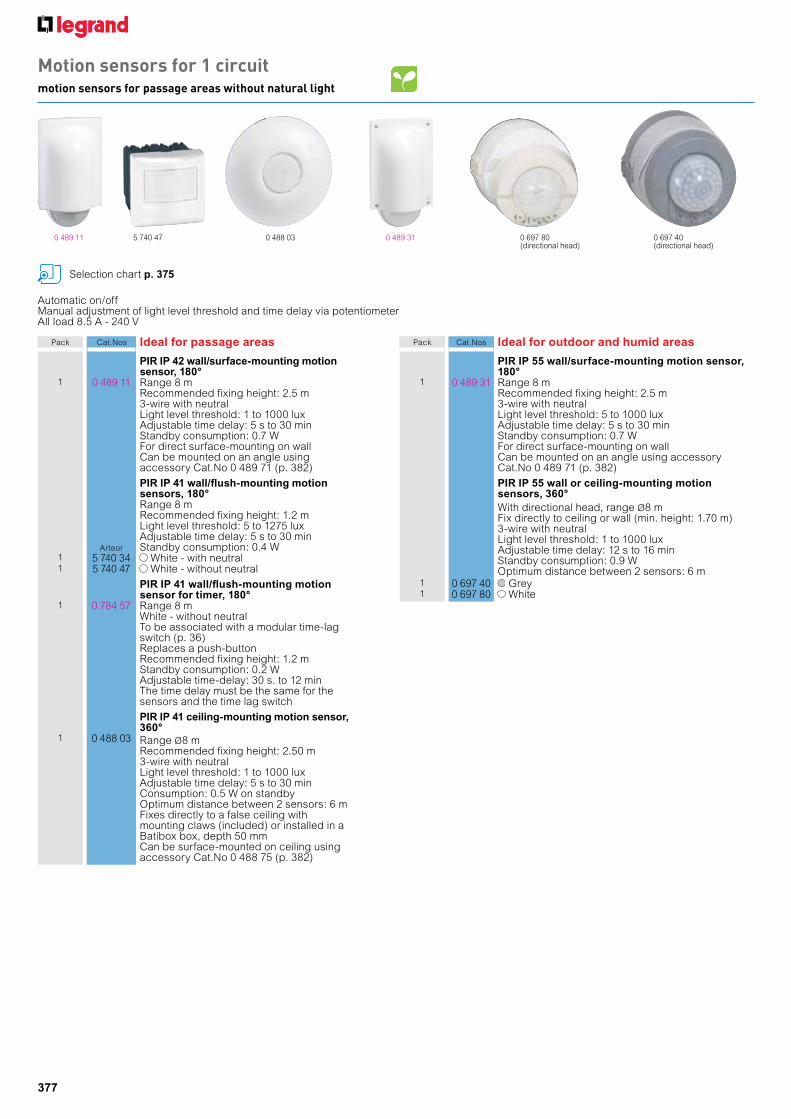
1 0 697 40 Grey1 0 697 80 White
0 697 80(directional head)
5 740 47 0 488 03 0 489 310 489 11
Motion sensors for 1 circuitmotion sensors for passage areas without natural light
Selection chart p. 375
0 697 40(directional head)
378
5 m
5 m
3 m
10 m
1.5 m3 m
10 m
1.2 m
1.5 m
1.3 m
0.5 m
3 m
1.5 m
3 m
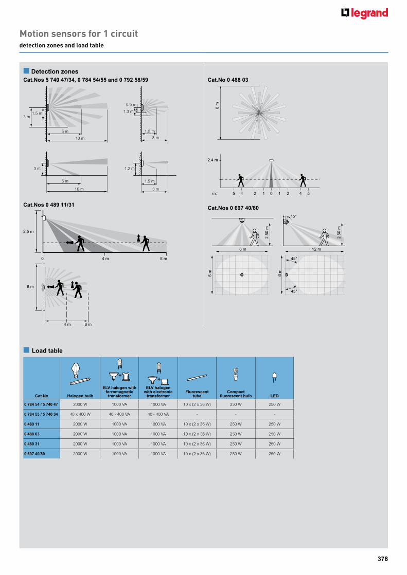
n Detection zonesCat.nos 5 740 47/34, 0 784 54/55 and 0 792 58/59 Cat.no 0 488 03
Cat.nos 0 489 11/31 Cat.nos 0 697 40/808
m
2.4 m
45 2 1 0 1 2 4 5m:
2.50
m
8 m 12 m
45°
15°
45°
6 m
6 m
2.50
m
Cat.no halogen bulb
eLV halogen with ferromagnetic transformer
eLV halogen with electronic
transformerFluorescent
tubeCompact
fluorescent bulb LeD
0 784 54 / 5 740 47 2000 W 1000 VA 1000 VA 10 x (2 x 36 W) 250 W 250 W
0 784 55 / 5 740 34 40 x 400 W 40 - 400 VA 40 - 400 VA - - -
0 489 11 2000 W 1000 VA 1000 VA 10 x (2 x 36 W) 250 W 250 W
0 488 03 2000 W 1000 VA 1000 VA 10 x (2 x 36 W) 250 W 250 W
0 489 31 2000 W 1000 VA 1000 VA 10 x (2 x 36 W) 250 W 250 W
0 697 40/80 2000 W 1000 VA 1000 VA 10 x (2 x 36 W) 250 W 250 W
n Load table
Motion sensors for 1 circuitdetection zones and load table
6 m
8 m4 m
2.5 m
4 m 8 m0
379
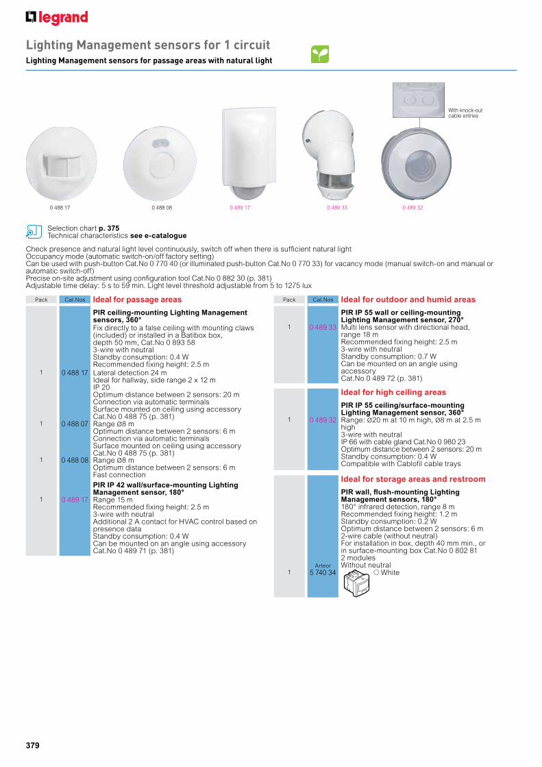
Lighting Management sensors for 1 circuitLighting Management sensors for passage areas with natural light
Check presence and natural light level continuously, switch off when there is sufficient natural lightOccupancy mode (automatic switch-on/off factory setting)Can be used with push-button Cat.No 0 770 40 (or illuminated push-button Cat.No 0 770 33) for vacancy mode (manual switch-on and manual or automatic switch-off)Precise on-site adjustment using configuration tool Cat.No 0 882 30 (p. 381)Adjustable time delay: 5 s to 59 min. Light level threshold adjustable from 5 to 1275 lux
Pack Cat.Nos ideal for passage areas
PiR ceiling-mounting Lighting management sensors, 360°Fix directly to a false ceiling with mounting claws (included) or installed in a Batibox box, depth 50 mm, Cat.No 0 893 583-wire with neutralStandby consumption: 0.4 WRecommended fixing height: 2.5 m
1 0 488 17 Lateral detection 24 mIdeal for hallway, side range 2 x 12 mIP 20Optimum distance between 2 sensors: 20 mConnection via automatic terminalsSurface mounted on ceiling using accessory Cat.No 0 488 75 (p. 381)
1 0 488 07 Range Ø8 mOptimum distance between 2 sensors: 6 mConnection via automatic terminalsSurface mounted on ceiling using accessory Cat.No 0 488 75 (p. 381)
1 0 488 08 Range Ø8 mOptimum distance between 2 sensors: 6 mFast connectionPiR iP 42 wall/surface-mounting Lighting management sensor, 180°
1 0 489 17 Range 15 mRecommended fixing height: 2.5 m3-wire with neutralAdditional 2 A contact for HVAC control based on presence dataStandby consumption: 0.4 WCan be mounted on an angle using accessory Cat.No 0 489 71 (p. 381)
Pack Cat.Nos ideal for outdoor and humid areas
PiR iP 55 wall or ceiling-mounting Lighting management sensor, 270°
1 0 489 33 Multi lens sensor with directional head, range 18 mRecommended fixing height: 2.5 m3-wire with neutralStandby consumption: 0.7 WCan be mounted on an angle using accessory Cat.No 0 489 72 (p. 381)
ideal for high ceiling areas
PiR iP 55 ceiling/surface-mounting Lighting management sensor, 360°
1 0 489 32 Range: Ø20 m at 10 m high, Ø8 m at 2.5 m high3-wire with neutralIP 66 with cable gland Cat.No 0 980 23Optimum distance between 2 sensors: 20 mStandby consumption: 0.4 WCompatible with Cablofil cable trays
ideal for storage areas and restroom
PiR wall, flush-mounting Lighting management sensors, 180°180° infrared detection, range 8 mRecommended fixing height: 1.2 mStandby consumption: 0.2 WOptimum distance between 2 sensors: 6 m2-wire cable (without neutral) For installation in box, depth 40 mm min., or in surface-mounting box Cat.No 0 802 812 modules Without neutralArteor
1 5 740 34 White
Selection chart p. 375Technical characteristics see e-catalogue
0 489 170 488 17 0 488 08
With knock-out cable entries
0 489 33 0 489 32

380
Lighting Management sensors for 1 circuitLighting Management sensors for working areas with natural light
Check presence and light level continuously, switch off when there is sufficient natural light Occupancy mode (automatic switch-on/off factory setting)Can be used with push-button Cat.No 0 770 40 (or illuminated push-button Cat.No 0 770 33) for vacancy mode (manual switch-on and manual or automatic switch-off)Infrared and ultrasonic Lighting Management sensors for workplaces, allowing precise presence detection as soon as the wave transmitted by the sensor is modified (for example, by hand movement on a keyboard)Precise on-site adjustment using configuration tool (p. 381)
Pack Cat.Nos ideal for working areas
Suitable for meeting room, classroom, open space, etc.
Dual technology ceiling-mounting Lighting management sensors, 360°Infrared and ultrasonic detection, Ø8 mIP 203-wire with neutralOptimum distance between 2 sensors: 6 mStandby consumption: 0.8 WFix directly to a false ceiling with mounting claws (included) or installed in a Batibox box, depth 50 mm
1 0 488 06 Connection via automatic terminalsCan be surface-mounted in ceiling using accessory Cat.No 0 488 75 (p. 381)
1 0 488 09 Fast connection
PiR technology wall/surface-mounting Lighting management sensor, 180°
1 0 489 14 With presence outputInfrared and ultrasonic detection, range (front) 8 mRecommended fixing height: 2.5 m3-wire with neutralIP 42Additional 2 A contact for HVAC control based on presence dataConsumption: 0.4 W on standbyOptimum distance between 2 sensors: 10 mCan be surface-mounted on ceiling using accessory Cat.No 0 489 71 (p. 381)
Dual technology wall/surface-mounting Lighting management sensor, 180°
1 0 489 16 With presence outputInfrared and ultrasonic detection, range (front) 8 mRecommended fixing height: 2.5 m3-wire with neutralIP 42Additional 2 A contact for HVAC control based on presence dataConsumption: 0.4 W on standbyOptimum distance between 2 sensors: 10 mCan be surface-mounted in ceiling using accessory Cat.No 0 489 71 (p. 381)
Pack Cat.Nos ideal for offices
Dual technology wall, flush-mounting Lighting management sensors, 180°Infrared and ultrasonic detection, range 8 mRecommended fixing height: 1.20 mStandby consumption: 0.2 WOptimum distance between 2 sensors: 6 m3-wire cableIP 41For installation in box, depth 40 mm min., or in surface-mounting box Cat.No 0 802 812 modulesArteor
1 5 740 49 With neutral1 5 740 31 Without neutral
PiR ceiling-mounting Lighting management sensors, 360°Range Ø8 m 3-wire with neutralOptimum distance between 2 sensors: 6 mStandby consumption: 0.8 WFix directly to a false ceiling with mounting claws (included) or installed in a Batibox box, depth 50 mmCan be surface-mounted in ceiling using accessory Cat.No 0 488 75 (p. 381)
1 0 488 00 Without 2 A contact for HVAC controlHigh density detection for desk workstationPIR - Ø4 m No load power consumption: 0.4 WVacany and occupany modeAll loads 8.5 A - 240 V±
1 0 488 04 With an additional 2 A contact for HVAC control, based on presence data
Selection chart p. 375Technical characteristics e-catalogue
0 488 09 0 489 16 0 488 045 740 31 / 5 740 49
Lighting Management sensor: Integrated
push-button
381
For advanced configuration:
For standard configuration:
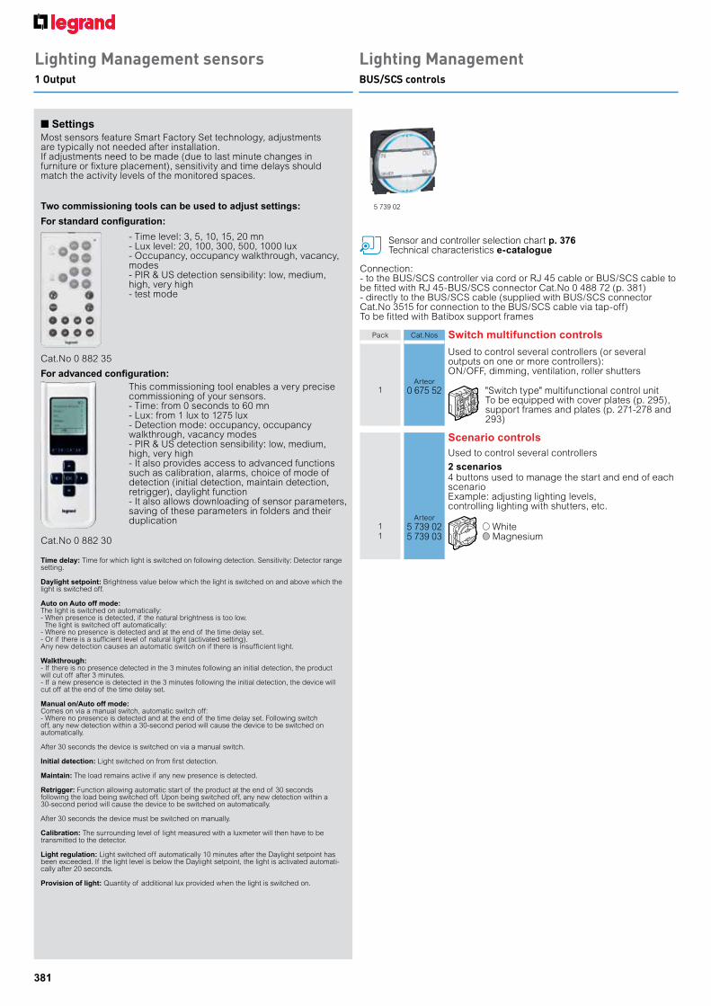
Cat.No 0 882 35
Cat.No 0 882 30
- Time level: 3, 5, 10, 15, 20 mn- Lux level: 20, 100, 300, 500, 1000 lux- Occupancy, occupancy walkthrough, vacancy, modes - PIR & US detection sensibility: low, medium, high, very high- test mode
This commissioning tool enables a very precise commissioning of your sensors.- Time: from 0 seconds to 60 mn- Lux: from 1 lux to 1275 lux- Detection mode: occupancy, occupancy walkthrough, vacancy modes- PIR & US detection sensibility: low, medium, high, very high- It also provides access to advanced functions such as calibration, alarms, choice of mode of detection (initial detection, maintain detection, retrigger), daylight function - It also allows downloading of sensor parameters, saving of these parameters in folders and their duplication
two commissioning tools can be used to adjust settings:
n SettingsMost sensors feature Smart Factory Set technology, adjustments are typically not needed after installation.If adjustments need to be made (due to last minute changes in furniture or fixture placement), sensitivity and time delays should match the activity levels of the monitored spaces.
Time delay: Time for which light is switched on following detection. Sensitivity: Detector range setting. Daylight setpoint: Brightness value below which the light is switched on and above which the light is switched off.
Auto on Auto off mode: The light is switched on automatically:- When presence is detected, if the natural brightness is too low. The light is switched off automatically:- Where no presence is detected and at the end of the time delay set. - Or if there is a sufficient level of natural light (activated setting). Any new detection causes an automatic switch on if there is insufficient light.
Walkthrough:- If there is no presence detected in the 3 minutes following an initial detection, the product will cut off after 3 minutes.- If a new presence is detected in the 3 minutes following the initial detection, the device will cut off at the end of the time delay set.
Manual on/Auto off mode:Comes on via a manual switch, automatic switch off: - Where no presence is detected and at the end of the time delay set. Following switch off, any new detection within a 30-second period will cause the device to be switched on automatically.
After 30 seconds the device is switched on via a manual switch.
Initial detection: Light switched on from first detection.
Maintain: The load remains active if any new presence is detected.
Retrigger: Function allowing automatic start of the product at the end of 30 seconds following the load being switched off. Upon being switched off, any new detection within a 30-second period will cause the device to be switched on automatically.
After 30 seconds the device must be switched on manually.
Calibration: The surrounding level of light measured with a luxmeter will then have to be transmitted to the detector.
Light regulation: Light switched off automatically 10 minutes after the Daylight setpoint has been exceeded. If the light level is below the Daylight setpoint, the light is activated automati-cally after 20 seconds.
Provision of light: Quantity of additional lux provided when the light is switched on.
Lighting Management sensors1 Output
Sensor and controller selection chart p. 376Technical characteristics e-catalogue
Lighting ManagementBUS/SCS controls
Connection:- to the BUS/SCS controller via cord or RJ 45 cable or BUS/SCS cable to be fitted with RJ 45-BUS/SCS connector Cat.No 0 488 72 (p. 381)- directly to the BUS/SCS cable (supplied with BUS/SCS connector Cat.No 3515 for connection to the BUS/SCS cable via tap-off)To be fitted with Batibox support frames
Used to control several controllers (or several outputs on one or more controllers): ON/OFF, dimming, ventilation, roller shutters
Arteor1 0 675 52 "Switch type" multifunctional control unit
To be equipped with cover plates (p. 295), support frames and plates (p. 271-278 and 293)
Scenario controlsUsed to control several controllers
2 scenarios4 buttons used to manage the start and end of each scenarioExample: adjusting lighting levels, controlling lighting with shutters, etc.
Arteor1 5 739 02 White1 5 739 03 Magnesium
Pack Cat.Nos Switch multifunction controls
5 739 02
382
Configuration tools and accessoriesConfiguration tools and accessories
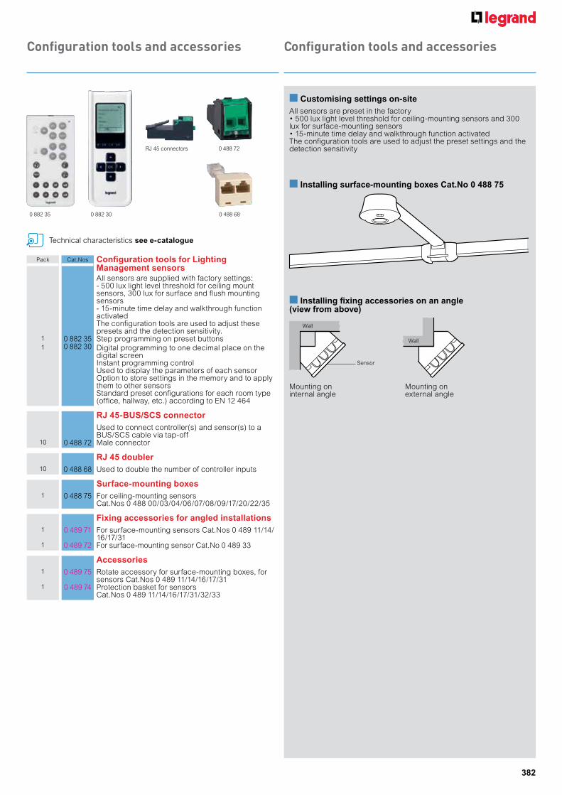
Pack Cat.Nos Configuration tools for Lighting management sensorsAll sensors are supplied with factory settings:- 500 lux light level threshold for ceiling mount sensors, 300 lux for surface and flush mounting sensors- 15-minute time delay and walkthrough function activatedThe configuration tools are used to adjust these presets and the detection sensitivity.
1 0 882 35 Step programming on preset buttons1 0 882 30 Digital programming to one decimal place on the
digital screenInstant programming control Used to display the parameters of each sensor Option to store settings in the memory and to apply them to other sensors Standard preset configurations for each room type (office, hallway, etc.) according to EN 12 464
RJ 45-BuS/SCS connectorUsed to connect controller(s) and sensor(s) to a BUS/SCS cable via tap-off
10 0 488 72 Male connector
RJ 45 doubler10 0 488 68 Used to double the number of controller inputs
Surface-mounting boxes1 0 488 75 For ceiling-mounting sensors
Cat.Nos 0 488 00/03/04/06/07/08/09/17/20/22/35
Fixing accessories for angled installations1 0 489 71 For surface-mounting sensors Cat.Nos 0 489 11/14/
16/17/311 0 489 72 For surface-mounting sensor Cat.No 0 489 33
accessories1 0 489 75 Rotate accessory for surface-mounting boxes, for
sensors Cat.Nos 0 489 11/14/16/17/311 0 489 74 Protection basket for sensors
Cat.Nos 0 489 11/14/16/17/31/32/33
0 882 35 0 882 30
0 488 72
0 488 68
RJ 45 connectors
n Customising settings on-siteAll sensors are preset in the factory • 500 lux light level threshold for ceiling-mounting sensors and 300 lux for surface-mounting sensors• 15-minute time delay and walkthrough function activatedThe configuration tools are used to adjust the preset settings and the detection sensitivity
Mounting on internal angle
Mounting on external angle
n installing surface-mounting boxes Cat.no 0 488 75
n installing fixing accessories on an angle (view from above)
Wall
Wall
Sensor
Technical characteristics see e-catalogue

383
Lighting Management sensors for managing several circuitsmulti-circuit ceiling-mounting controllers for areas with natural light
Ceiling-mounting or installation in Cablofil cable trays (see Legrand Cable Management catalogue)Connection to sensors (Cat.Nos 0 488 20/22/30/24/23/25 and 0 784 85/86, 5 740 46/48) by cord or RJ 45 cable (p. 416) or BUS/SCS cable to be fitted with RJ 45 connector Cat.No 0 488 72 (p. 382)
Sensor and controller selection chart p. 376Technical characteristics see e-catalogue
Rear view Connection via
screw terminals
0 488 51
DALI 1
DALI 2
Local control solutions
Rear view Connection via screw terminals
0 488 41
Pack Cat.Nos For controlling 1 or 2 circuits in one room
1 sensor input, 2 inputs for auxiliaries2 outputsCan be used with a push-button, including a push-button with LED indicator, Cat.Nos 0 770 40/33 for manual switch-on and manual or automatic switch-off
On/OFF1 0 488 50 2 x 16 A outputs
Used to control 2 ON/OFF lighting circuits or 1 lighting circuit + 1 ventilation circuitConnection via screw terminals
Dimming - DaLi ballast1 0 488 51 2 DALI outputs (32 ballasts max.) and 1 ventilation
output (volt-free contact)Used to vary the light level on the window side of a room (where there is more natural light) separately from the hallway sideUsed to control a maximum of 32 DALI ballastsConnection via screw terminals
Dimming - 1-10 V ballast1 0 488 52 2 x 1000 VA lighting outputs
Used to vary the light level on the window side of a room (where there is more natural light) separately from the hallway sideConnection via screw terminals
For controlling 2 lighting circuitsCan be controlled for each output by a sensor and/or an individual BUS control unitAddressing methods using sensors and control units:- automatic configuration- custom configuration by pressing the "Learn" button on the product
On/OFF1 0 488 41 2 x 16 A outputs
Dimming - 1-10 V ballast1 0 488 42 2 outputs
1000 VA maximum per output
Dimming - LV and eLV halogen1 0 488 45 2 outputs
1000 W maximum per output
Pack Cat.Nos For controlling 4 lighting circuits
Can be controlled for each output by a sensor and/or an individual BUS control unitAddressing methods using sensors and control units:- automatic configuration- custom configuration by pressing the "Learn" button on the product
Dimming - ballast 1-10 V or On/OFF1 0 488 43 4 outputs
1000 VA maximum per output
Dimming - DaLi ballast1 0 488 44 4 outputs
32 ballasts maximum per output
For controlling 2 lighting circuits, 1 shutter and 1 hVaC contactCan be controlled for each output by a sensor and/or an individual BUS control unitAddressing methods using sensors and control units:- automatic configuration- custom configuration by pressing the "Learn" button on the product
1 0 488 47 2 ON/OFF or 1-10 V dimming lighting outputs 1 output for roller shutters1 ventilation output (volt-free contact)

384
Lighting Management sensors for managing several circuitsLighting Management sensors for controllers for passage areas and working areas with natural light
Check presence and light level continuously, switch off when there is sufficient natural lightAutomatic switch-on/off (factory setting)Precise on-site adjustment using configuration tool (p. 382)Connect to controllers by cord or RJ 45 cable or BUS/SCS cable to be fitted with RJ 45 connector Cat.No 0 488 72 (p. 382)
Pack Cat.Nos ideal for large areas
PiR technology ceiling-mounting Lighting management sensor, 360°
1 0 488 20 Range Ø8 m IP 20Optimum distance between 2 sensors: 6 mConsumption: 0.2 W on standbyFixes directly to a false ceiling with mounting claws (included) or installed in a Batibox box, depth 50 mmCan be surface-mounted on ceiling using accessory Cat.No 0 488 75
PiR technology wall/surface-mounting Lighting management sensor, 140°
1 0 488 25 With directional head, range 30 mIP 42Consumption: 0.2 W on standbySupplied with fixing plate
PiR technology wall, flush-mounting Lighting management sensors, 180°Arteor
1 5 740 46 Range 8 mRecommended fixing height: 1.2 mIP 41Consumption: 0.2 W on standby
Integrated push-buttonFor installation in box, depth 40 mm min., or in surface-mounting box Cat.No 0 802 812 modules
PiR technology wall/surface-mounting Lighting management sensor, 180°
1 0 488 24 With directional head, range (front) 5 mIP 42Consumption: 0.2 W on standbySupplied with fixing plate
ideal for outdoor and humid areasPiR technology wall/surface-mounting Lighting management sensor, 270°
1 0 488 30 Detection: side range 2 x 15 m and front range 10 mIP 55Consumption: 0.5 W on standbySupplied with fixing plate
Sensor and controller selection chart p. 376Technical characteristics see e-catalogue
Pack Cat.Nos ideal for working areas
ArteorDual technology wall, flush-mounting Lighting management sensors, 180°
1 5 740 48 Infrared and ultrasonic detection, range 8 mRecommended fixing height: 1.2 mIP 41
Consumption: 0.2 W on standbyIntegrated push-buttonFor installation in box, depth 40 mm min., or in surface-mounting box Cat.No 0 802 812 modules
Dual technology ceiling-mounting Lighting management sensor, 360°
1 0 488 22 Infrared and ultrasonic detection, range Ø8 mRecommended fixing height: 2.50 m IP 20Optimum distance between 2 sensors: 6 mConsumption: 0.5 W on standbyFixes directly to a false ceiling with mounting claws (included) or installed in a Batibox box, depth 50 mmCan be surface-mounted on ceiling using accessory Cat. No 0 488 75 (p. 382)
Dual technology wall/surface-mounting Lighting management sensor, 180°
1 0 488 23 Infrared and ultrasonic detection with directional head, range (front) 7 mConsumption: 0.5 W on standbySupplied with fixing plate
Light level measurement cell1 0 488 28 For synchronising the light level
measurement when used with sensors Use the configuration tool Cat.No 0 882 30 (p. 382) to configure the light level cell Connects to the BUS/SCS cable with connector Cat.No 0 488 72 IP 20
RJ 45-BuS/SCS connectorsUsed to connect controller(s) and sensor(s) to a BUS/SCS cable via tap-off
10 0 488 72 Male connector10 0 488 73 Female connector
Local control solutions
0 488 23(IR + US detection)
0 488 25(IR detection)
Connection to controller via cord or RJ 45 cable 0 488 22 (IR + US detection)
5 740 48
Integrated push-button

385
Green products are becoming increasingly popular and the overall economy is slowly transformed into an economy that is more sustainable and earth-friendly. In addition, as green economies grow, the costs of individual items will come down, due to the increased efficiency of larger production runs.
Legrand is pleased to present the following awarded sensors:
Legrand sensors awarded SGBP certification
0 488 17PIR ceiling mounted Lighting Management sensors 360° infrared dual detectionIdeal for hallway, side range 2 x 12mIdeal for data centre and corridor
0 488 06Dual technology ceiling mountedLighting Management sensors Surface mounted on ceiling using accessory
0 488 00PIR High Density Sensor360° detection angleSurface mounted on ceiling using accessory
0 488 04PIR ceiling mounted Lighting Management Sensors360° infrared detection, ø8m rangeAdditional 2A contact for HVAC control based on presence dataSurface mounting on ceiling using accessory
0 488 10270° outdoor sensor IP 55Detection field 180m² - For building entrances, car parksPIR - Max range 15mFront detection 10mLateral detection 30m (2x15)Dual side detection specially adapted for wide areas (example: entrance hall)
0 488 05US technology ceiling mountedLighting Management sensors Surface mounted on ceiling using accessory
Additional Green Features:
• Manual on/ Auto off• Walk through mode• Built-in photocell• Air conditioning control• 3rd Party Interface
THE GLOBAL SPECIALISTIN ELECTRICAL AND DIGITAL BUILDING INFRASTRUCTURES

386
Green products are becoming increasingly popular and the overall economy is slowly transformed into an economy that is more sustainable and earth-friendly. In addition, as green economies grow, the costs of individual items will come down, due to the increased efficiency of larger production runs.
Legrand is pleased to present the following awarded sensors:
Legrand sensors awarded SGBP certification
0 488 17PIR ceiling mounted Lighting Management sensors 360° infrared dual detectionIdeal for hallway, side range 2 x 12mIdeal for data centre and corridor
0 488 06Dual technology ceiling mountedLighting Management sensors Surface mounted on ceiling using accessory
0 488 00PIR High Density Sensor360° detection angleSurface mounted on ceiling using accessory
0 488 04PIR ceiling mounted Lighting Management Sensors360° infrared detection, ø8m rangeAdditional 2A contact for HVAC control based on presence dataSurface mounting on ceiling using accessory
0 488 10270° outdoor sensor IP 55Detection field 180m² - For building entrances, car parksPIR - Max range 15mFront detection 10mLateral detection 30m (2x15)Dual side detection specially adapted for wide areas (example: entrance hall)
0 488 05US technology ceiling mountedLighting Management sensors Surface mounted on ceiling using accessory
Additional Green Features:
• Manual on/ Auto off• Walk through mode• Built-in photocell• Air conditioning control• 3rd Party Interface
THE GLOBAL SPECIALISTIN ELECTRICAL AND DIGITAL BUILDING INFRASTRUCTURES
FullycompatiblesmartinfrastructureLegrand’s active building management solutions are based on a smart communication infrastructure compatible with various protocols such as KNX, Modbus, DALI and Bacnet
BUS/KNX gateway - IP
Management interface for addressable units
LighTing,BLinDs, POWeR
eMeRgenCY LighTing
heATing, VenTiLATiOn, AiR COnDiTiOning(hVAC)
ACCess COnTROL, CCTV
iP KnX iP BACneT
MeAsUReMenT
RS 485/IP converter
iP MODBUs
iP inFRAsTRUCTURe
Possibility to integrate applications other than Legrand’s
Building manager viewerSoftware+ Building manager controllerAutomatic control system
Visualize,manage,be informed,interact
387
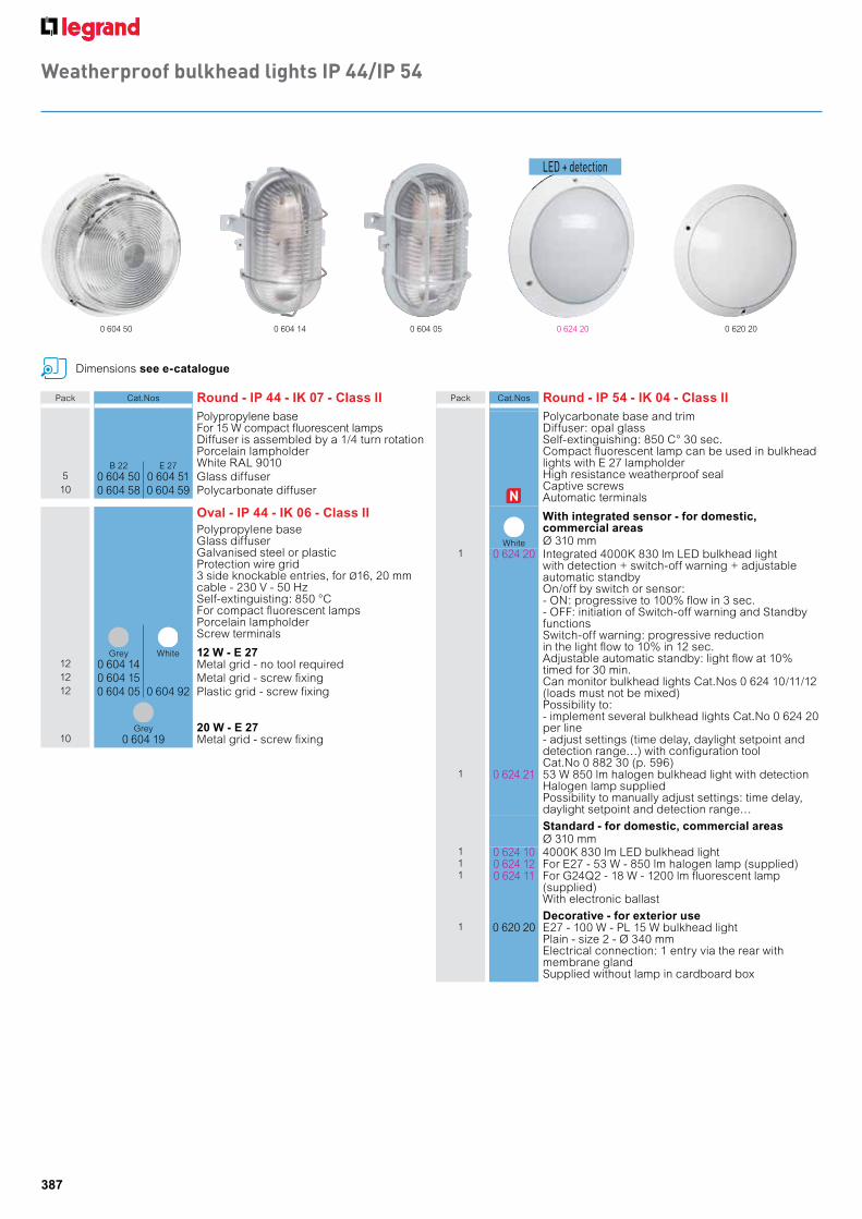
0 604 50 0 604 14 0 604 05 0 624 20
Pack Cat.Nos Round - iP 44 - ik 07 - Class iiPolypropylene base For 15 W compact fluorescent lampsDiffuser is assembled by a 1/4 turn rotationPorcelain lampholderWhite RAL 9010B 22 E 27
5 0 604 50 0 604 51 Glass diffuser10 0 604 58 0 604 59 Polycarbonate diffuser
Oval - iP 44 - ik 06 - Class iiPolypropylene baseGlass diffuserGalvanised steel or plasticProtection wire grid3 side knockable entries, for Ø16, 20 mmcable - 230 V - 50 HzSelf-extinguisting: 850 °CFor compact fluorescent lampsPorcelain lampholderScrew terminals
Grey
White 12 w - e 27
12 0 604 14 Metal grid - no tool required12 0 604 15 Metal grid - screw fixing12 0 604 05 0 604 92 Plastic grid - screw fixing
Grey 20 w - e 27
10 0 604 19 Metal grid - screw fixing
Dimensions see e-catalogue
Pack Cat.Nos Round - iP 54 - ik 04 - Class iiPolycarbonate base and trimDiffuser: opal glassSelf-extinguishing: 850 C° 30 sec.Compact fluorescent lamp can be used in bulkhead lights with E 27 lampholderHigh resistance weatherproof sealCaptive screwsAutomatic terminals
White
with integrated sensor - for domestic, commercial areas Ø 310 mm
1 0 624 20 Integrated 4000K 830 lm LED bulkhead light with detection + switch-off warning + adjustable automatic standbyOn/off by switch or sensor:- ON: progressive to 100% flow in 3 sec.- OFF: initiation of Switch-off warning and Standby functionsSwitch-off warning: progressive reduction in the light flow to 10% in 12 sec.Adjustable automatic standby: light flow at 10% timed for 30 min.Can monitor bulkhead lights Cat.Nos 0 624 10/11/12 (loads must not be mixed)Possibility to:- implement several bulkhead lights Cat.No 0 624 20 per line- adjust settings (time delay, daylight setpoint and detection range…) with configuration tool Cat.No 0 882 30 (p. 596)
1 0 624 21 53 W 850 lm halogen bulkhead light with detectionHalogen lamp suppliedPossibility to manually adjust settings: time delay, daylight setpoint and detection range…
Standard - for domestic, commercial areas Ø 310 mm
1 0 624 10 4000K 830 lm LED bulkhead light1 0 624 12 For E27 - 53 W - 850 lm halogen lamp (supplied)1 0 624 11 For G24Q2 - 18 W - 1200 lm fluorescent lamp
(supplied) With electronic ballast
Decorative - for exterior use1 0 620 20 E27 - 100 W - PL 15 W bulkhead light
Plain - size 2 - Ø 340 mmElectrical connection: 1 entry via the rear with membrane glandSupplied without lamp in cardboard box
0 620 20
Weatherproof bulkhead lights IP 44/IP 54
LED + detection
388
Dimensions see e-catalogue
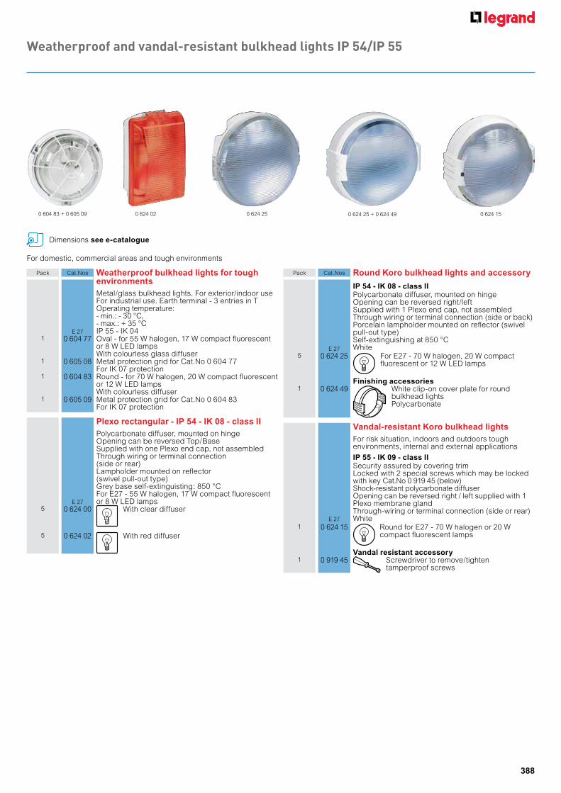
Pack Cat.Nos weatherproof bulkhead lights for toughenvironments
E 27
Metal/glass bulkhead lights. For exterior/indoor useFor industrial use. Earth terminal - 3 entries in TOperating temperature: - min.: - 30 °C, - max.: + 35 °CIP 55 - IK 04
1 0 604 77 Oval - for 55 W halogen, 17 W compact fluorescent or 8 W LED lampsWith colourless glass diffuser
1 0 605 08 Metal protection grid for Cat.No 0 604 77For IK 07 protection
1 0 604 83 Round - for 70 W halogen, 20 W compact fluorescent or 12 W LED lampsWith colourless diffuser
1 0 605 09 Metal protection grid for Cat.No 0 604 83For IK 07 protection
Plexo rectangular - iP 54 - ik 08 - class ii
E 27
Polycarbonate diffuser, mounted on hingeOpening can be reversed Top/BaseSupplied with one Plexo end cap, not assembledThrough wiring or terminal connection(side or rear)Lampholder mounted on reflector(swivel pull-out type)Grey base self-extinguisting: 850 °CFor E27 - 55 W halogen, 17 W compact fluorescent or 8 W LED lamps
5 0 624 00 With clear diffuser
5 0 624 02 With red diffuser
Pack Cat.Nos Round koro bulkhead lights and accessory
iP 54 - ik 08 - class ii
E 27
Polycarbonate diffuser, mounted on hingeOpening can be reversed right/leftSupplied with 1 Plexo end cap, not assembledThrough wiring or terminal connection (side or back)Porcelain lampholder mounted on reflector (swivelpull-out type) Self-extinguishing at 850 °C White
5 0 624 25 For E27 - 70 W halogen, 20 W compact fluorescent or 12 W LED lamps
Finishing accessories1 0 624 49 White clip-on cover plate for round
bulkhead lightsPolycarbonate
Vandal-resistant koro bulkhead lightsFor risk situation, indoors and outdoors toughenvironments, internal and external applications
iP 55 - ik 09 - class ii
E 27
Security assured by covering trim Locked with 2 special screws which may be locked with key Cat.No 0 919 45 (below) Shock-resistant polycarbonate diffuser Opening can be reversed right / left supplied with 1 Plexo membrane gland Through-wiring or terminal connection (side or rear) White
1 0 624 15 Round for E27 - 70 W halogen or 20 W compact fluorescent lamps
Vandal resistant accessory1 0 919 45 Screwdriver to remove/tighten
tamperproof screws
For domestic, commercial areas and tough environments
0 624 02 0 624 25 0 624 25 + 0 624 49 0 624 150 604 83 + 0 605 09
Weatherproof and vandal-resistant bulkhead lights IP 54/IP 55

389
Access control stand-alone badge readers
Access control stand-alone keypads
Pack Cat.Nos Internal coded keypads
For mounting in flush or surface-mounting boxes (5 modules)Can be used in stand-alone or centralised mode100 user codes in stand-alone mode1 pushbutton input for internal unlocking1 relay output for door release or electromagneticlock10 000 codes in centralised mode with door controller Cat.No 0 767 04 (Compatible with Wiegand protocol)Consumption 100 mA - 12 V=IP 40 - IK 04
Arteor1 5 722 52 White internal coded keypad
Supplied with support and finishing plate1 5 727 52 Black Mirror internal coded keypad
Supplied with support and finishing plate
External coded keypadsSoliroc
1 0 778 76 External coded keypadBacklit buttonsSurface-mounting100 user codes in stand-alone mode1 self-protection contact (pull out + opening)
1 pushbutton input for internal unlocking1 relay output for door release or electromagnetic lockPower supply 12/24 VA/=Consumption 80 mA at 12 V=IP 55 - IK 10
1 0 778 78 External coded keypad with call buttonBacklit buttonsSurface-mounting, cable outlet100 user codes in stand-alone mode 1 self-protection contact (pull out + opening)
1 pushbutton input for internal unlocking1 relay output for door release or electromagnetic lock1 N/O pushbutton on frontPower supply 12/24 VA/=Consumption 80 mA at 12 V=IP 55 - IK 10
Pack Cat.Nos Internal badge readers
For mounting in flush or surface-mounting boxes (5 modules)Can be used in stand-alone or centralised mode 500 user badges in stand-alone mode1 pushbutton input for internal unlocking1 relay output for door release or electromagnetic lock10 000 badges in centralised mode with door controller Cat.No 0 767 04 (Compatible with Wiegand protocol)Consumption 118 mA - 12 V= - IP 40 - IK 04
Arteor1 5 722 51 White internal badge reader
Supplied with support and finishing plate1 5 727 51 Black Mirror internal badge reader
Supplied with support and finishing plate
External badge readersSoliroc
1 0 778 72 Surface-mounting external badge readerBacklit detection areaSurface-mounting, cable outlet500 user badges in stand-alone mode 1 self-protection contact (pull out + opening)
1 pushbutton input for internal unlocking. 1 relay output for door release or electromagnetic lock.Power supply 12/24 VA/=Consumption 80 mA - 12 V= - IP 55 - IK 10
0 778 78 0 778 72 5 722 51
All readers have indicators and a buzzer to indicate the door status All readers have indicators and a buzzer to indicate the door status
5 722 52

390
Access control stand-alone biometric readers, energy saver units and badges
0 767 30 0 767 10
Pack Cat.Nos Biometric readers
For mounting in flush or surface-mounting boxes (5 modules)Can be used in stand-alone or centralised mode 999 user fingerprints in stand-alone mode1 pushbutton input for internal unlocking1 relay output for door release or electromagnetic lock999 fingerprints in centralised mode with door controller Cat.No 0 767 04 (Compatible with Wiegand protocol)Consumption 145 mA - 12 VIP 40 - IK 04
Arteor1 5 722 50 White biometric fingerprint reader
Supplied with support and finishing plate1 5 727 50 Black Mirror biometric fingerprint reader
Supplied with support and finishing plate
Vein pattern biometric reader1 0 767 30 Surface-mounting (protection kit on
request)Operates in stand-alone mode with the door opening device connected directly to the reader, or in centralised mode, connected to door controller, Cat.No 0 767 04
1 000 vein patterns stored, in both stand-alone and centralised modeReads vein pattern only, or badge associated with a vein pattern1 self-protection contact (pull out + opening)Power supply 12 V=Consumption 300 mAIP 43 - IK 04
Energy saver unitsFor switching on a circuit, for example in a meeting room, office, hotel rooms, etc. Only operate with Mifare ISO contactless badges Cat.Nos 0 767 11/12/13 30 s time delay after removal of the badge Low capacity contact: 230 V power 0.25 A Luminous strip on the front so you can see it when you enter the room
1 5 722 53 Arteor white1 5 727 53 Arteor magnesium
Pack Cat.Nos Badges
5 0 767 10 MIFARE contactless badge key fob13.56 MHzWith customisable tab included
10 0 767 11 MIFARE contactless badge cardISO format (50 x 80 mm)Chip: 13.56 MHzStandard 1 KB memory
Closing accessories1 0 767 07 Electromagnetic lock 300 kg
Indicates the position of the door by 2-colour LED and forwarding possible by changeover contact Control of the door position by Hall effect Consumption: 24 V - 300 mA - 7.2 W, 12 V - 600 mA - 7.2 W
1 0 408 95 Undervoltage door release 12 V= - 600 mA For operation in emergency exits Dimensions: 158 x 26 x 32 mm
1 0 408 98 Shunt trip door release 12 V= 6 W - 500 mA Dimensions: 158 x 26 x 32 mm
Protected power supply1 0 767 18 12 V= - 4 A power supply
Backed up by 12 V - 7 Ah battery Cat.No 0 407 49 (not supplied)
All readers have indicators and a buzzer to indicate the door status
Biometric solutions
391
Access control centralisedAccess control stand-alone
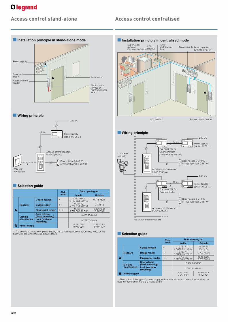
n Installation principle in stand-alone mode
n Selection guide
Power supply
Standard cable
Access control reader
Electric door release or electromagnetic lock
Pushbutton
Risk level
Door opening to:
Inside Outside
A
Readers
Coded keypad + 0 767 00/415 722 52/5 727 52 0 778 76/78
Badge reader ++ 0 767 42 5 722 51/5 727 51 0 778 72
Fingerprint reader +++ 0 767 03 5 722 50/5 727 50
tailor made0 767 30
Closing accessories
Door release (flush mounting) 0 408 95/96/98
Lock (surface-mounting) 0 767 07/08/09
B Power supply 4 131 05(1)
0 047 92(1)0 767 18 + 0 407 49(1)
1: The choice of the type of power supply, with or without battery, determines whether thedoor will open when there is a mains failure
A
B
n Wiring principle230 V±
12 V=
2
2
2 2
Way OutPushbutton
Power supply(ex: 0 047 95,...)
Door release 3 749 00or magnetic lock 0 767 07
Access control readers0 767 03/41/42
n Installation principle in centralised modeSupervision software Cat.No 0 767 06
VDI network
Area distribution box
VDI cabinet
Power supply Door controller (Cat.No 0 767 04)
Access control reader
A
B
n Wiring principle230 V±
12 V=Power supply(ex: 4 131 05 ,...)
Cat.No 0 767 04Door controller(2 doors max. per unit)
Door release 3 749 00or magnetic lock 0 767 07
Local area network
5
2
2
Access control readers0 767 03/43/44
230 V±
12 V=Power supply(ex: 4 131 05 ,...)
Cat.No 0 767 04Door controller
Door release 3 749 00or magnetic lock 0 767 07
52
2
Access control readers0 767 03/43/44
Up to 128 door controllers
n Selection guide
Risk level
Door opening to:
Inside Outside
A
Readers
Coded keypad + 0 767 43 5 722 52/5 757 52
0 767 17 0 778 73
Badge reader ++ 0 767 44 5 722 51/5 727 51 0 767 16/32
Fingerprint reader +++ 0 767 03 5 722 50/5 727 50
tailor made0 767 30/31
Closing accessories
Door release (flush mounting) 0 408 95/96/98
Lock (surface-mounting) 0 767 07/08/09
B Power supply 4 131 05(1)
0 047 92(1)0 767 18 + 0 407 49(1)
1: The choice of the type of power supply, with or without battery, determines whether thedoor will open when there is a mains failure
392
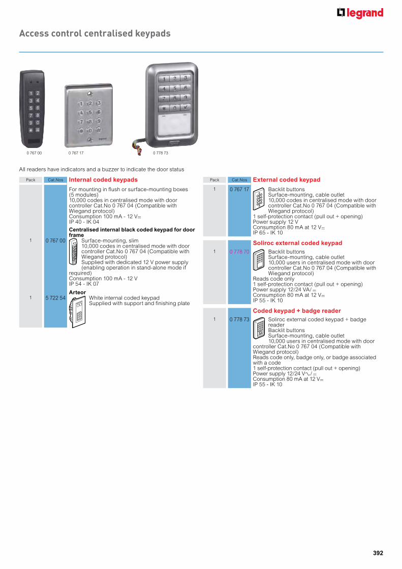
Pack Cat.Nos External coded keypad
1 0 767 17 Backlit buttonsSurface-mounting, cable outlet10,000 codes in centralised mode with door controller Cat.No 0 767 04 (Compatible with Wiegand protocol)
1 self-protection contact (pull out + opening) Power supply 12 VConsumption 80 mA at 12 V=IP 65 - IK 10
Soliroc external coded keypad1 0 778 70 Backlit buttons
Surface-mounting, cable outlet10,000 users in centralised mode with doorcontroller Cat.No 0 767 04 (Compatible withWiegand protocol)
Reads code only1 self-protection contact (pull out + opening)Power supply 12/24 VA/=Consumption 80 mA at 12 V=IP 55 - IK 10
Coded keypad + badge reader1 0 778 73 Soliroc external coded keypad + badge
reader Backlit buttonsSurface-mounting, cable outlet10,000 users in centralised mode with door
controller Cat.No 0 767 04 (Compatible with Wiegand protocol)Reads code only, badge only, or badge associated with a code1 self-protection contact (pull out + opening)Power supply 12/24 VA/=Consumption 80 mA at 12 V=IP 55 - IK 10
Access control centralised keypads
0 767 00 0 767 17 0 778 73
Pack Cat.Nos Internal coded keypads
For mounting in flush or surface-mounting boxes (5 modules)10,000 codes in centralised mode with door controller Cat.No 0 767 04 (Compatible with Wiegand protocol)Consumption 100 mA - 12 V=IP 40 - IK 04
Centralised internal black coded keypad for door frame
1 0 767 00 Surface-mounting, slim10,000 codes in centralised mode with door controller Cat.No 0 767 04 (Compatible with Wiegand protocol)Supplied with dedicated 12 V power supply (enabling operation in stand-alone mode if
required)Consumption 100 mA - 12 VIP 54 - IK 07
Arteor1 5 722 54 White internal coded keypad
Supplied with support and finishing plate
All readers have indicators and a buzzer to indicate the door status

393
Access control centralised badge readers and biometric readers
Pack Cat.Nos Internal badge readers
10 000 codes in centralised mode with door controller Cat.No 0 767 04 (compatible with Wiegand protocol)Consumption: 100 mA - 12 V=IP 40 - IK 04
Arteor1 5 722 55 White internal badge reader
Supplied with support and finishing plate
External badge readersSoliroc external badge reader
1 0 778 71 Backlit buttonsSurface-mounting, cable outlet10,000 users in centralised mode with doorcontroller Cat.No 0 767 04 (Compatible withWiegand protocol)
Badge only, or badge associated with a code1 self-protection contact (pull out + opening)Power supply 12/24 VA/=Consumption 80 mA at 12 V=IP 55 - IK 10
External badge reader1 0 767 16 Surface-mounting, slim, cable outlet
10,000 user badges in centralised mode withdoor controller Cat.No 0 767 04 (Compatible with Wiegand protocol)
1 self-protection contact (pull out)Power supply 12 VConsumption 80 mA - 12 V= - IP 65 - IK 10
Badge reader for car park1 0 767 32 Long distance external badge reader
Surface mounted, cable outlet10,000 user badges in centralised modewith door controller Cat.No 0 767 04 (Compatible with Wiegand protocol) Only operates with dual technology badge
Cat.No 0 767 12 1 self-protection contact (pull out)Power supply 12 VConsumption 350 mA - 12 V= - IP 54 - IK 08
5 722 50 0 767 30
Pack Cat.Nos Biometric readers
For mounting in flush-mounting box or surface-mounting (5 modules)Can be used in stand-alone or centralised mode 999 user fingerprints in stand-alone mode1 pushbutton input for internal unlocking1 relay output for door release or electromagnetic lock999 fingerprints in centralised mode with door controller Cat.No 0 767 04 (Compatible with Wiegand protocol)Consumption 145 mA - 12 VIP 40 - IK 04
Arteor white biometric fingerprint reader1 5 722 50 Supplied with support and finishing plate
Vein pattern biometric reader1 0 767 30 Surface-mounting (protection kit on
request)Operates in stand-alone mode with the door opening device connected directly to the reader, or in centralised mode, connected to door controller,
Cat.No 0 767 04 1000 vein patterns stored, in both stand-alone and centralised modeReads vein pattern only, or badge associated with a vein pattern1 self-protection contact (pull out + opening)Power supply 12 V=Consumption 300 mAIP 43 - IK 04
Biometric fingerprint + badge reader1 0 767 31 Surface-mounting
10,000 users in centralised mode with door controller Cat.No 0 767 04 (Compatible with Wiegand protocol)
Reads fingerprint only (max. 250 fingerprints), or badge associated with a fingerprint1 self-protection contact (pull out + opening)Power supply 12 V=Consumption 300 mAIP 44 - IK 04
All readers have indicators and a buzzer to indicate the door status
0 767 16
Biometric solutions
0 778 71
394
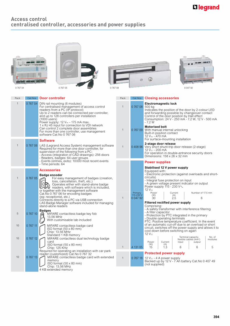
Access control centralised controller, accessories and power supplies
0 767 04 0 767 05 0 767 08 0 047 92
Pack Cat.Nos Door controller
1 0 767 04 DIN rail mounting (6 modules)For centralised management of access control readers from a PC (IP protocol)Up to 2 readers can be connected per controller, and up to 128 controllers per installation (1000 users)Power supply: 12 V= - 175 mA max.1 x RJ 45 input for connection to VDI networkCan control 2 complete door assembliesFor more than one controller, use management software Cat.No 0 767 06
Software1 0 767 06 LAS (Legrand Access System) management software
Required for more than one door controller, for supervision of the following from a PC:- Access (integration of CAD drawings): 256 doors- Readers, badges: 64 user groups- Events (entries, exits): 10 000 most recent events- Time periods: 64
AccessoriesBadge encoder
1 0 767 05 For easy management of badges (creation, loss, cancellation, theft, etc.)Operates either with stand-alone badge readers, with software which is included,
or together with the management software Cat.No 0 767 06 for encoding badges (eg: receptionist, etc.)Connects directly to a PC via USB connectionLAS Badge Manager software included for managing stand-alone readers
Badges5 0 767 10 MIFARE contactless badge key fob
13.56 MHzWith customisable tab included
10 0 767 11 MIFARE contactless badge cardISO format (50 x 80 mm)Chip: 13.56 MHzStandard 1 KB memory
10 0 767 12 MIFARE contactless dual technology badge cardISO format (50 x 80 mm)Chip: 125 KHz
Required for operating an installation with car park reader (customized) Cat.No 0 767 32
10 0 767 13 MIFARE contactless badge card with extended memoryISO format (50 x 80 mm)Chip: 13.56 MHz
4 KB extended memory
Pack Cat.Nos Closing accessories
Electromagnetic lock1 0 767 08 500 kg
Indicates the position of the door by 2-colour LED and forwarding possible by changeover contact Control of the door position by Hall effect Consumption: 24 V - 250 mA - 7.2 W, 12 V - 500 mA - 7.2 W
Motorised bolt1 0 767 09 With manual internal unlocking
Built-in position contact12 V= - 470 mAFor surface-mounting installation
2-stage door release1 0 408 96 Very short shunt-trip door release (2-stage)
12 V= - 200 mAFor operation in double-entrance security doors Dimensions: 158 x 26 x 32 mm
Power supplies
Stabilised 12 V power supplyEquipped with:- Electronic protection (against overloads and short-circuits)- Integral fuse protection on input- A green voltage present indicator on outputPower supply 115 - 230 VA12 V=
Primary115-230 V
Power(W)
Current(A)
Number of 17.5 mm
1 0 047 92 30 2.5 6
Filtered rectified power supplyComprising:- A safety transformer with interference filtering- A filter capacitor- Protection by PTC integrated in the primary- Double operating terminalsPTC: Positive temperature coefficient. In the event of an automatic cut-off due to an overload or short circuit, switches off the power supply and allows it to cool down before switching on again12 V=
Terminal capacityflexible cables (mm2)
No. of modules
Power(W)
Current(A)
input output
1 4 131 05 15 1.3 6 6 5
Protected power supply1 0 767 18 12 V= - 4 A power supply
Backed up by 12 V - 7 Ah battery Cat.No 0 407 49 (not supplied)