Embed Size (px)
Citation preview

Erling H. Stenby
Center for Energy Resources Engineering - CERE
Technical Universiy of Denmark, DTU
New Important Insight into CO2
EOR in Different Types of Chalk

Co-authors:
M. Monzurul Alam, Ben Niu, Ida L. Fabricius, Wei Yan,Center for Energy Resources Engineering, DTU
Helle F. Christensen, Frederik P. Ditlevsen, Morten L. Hjuler, Danish Geotechnical Institute, GEO
Dan Olsen, Geological Survey of Denmark and Greenland

EOR through CO2 Utilization
• Question to be answered:
– Is there a potential for CO2 EOR in Denmark usingCO2 from Danish sources?
• DONG Energy Power Generation, DONG Energy E&P, CERE DTU, GEO, GEUS
• Funding: DONG Energy, HTF, DTU, GEO and GEUS
• Duration: 1 January 2007 – 30 June 2010…

What did we investigate?
• How does CO2 influence the properties of chalk?
• How does CO2 influence the properties of a specific Danish reservoir oil?
• How well does CO2 displace residual oil afterwaterflooding in different types of chalk?
• Core material, flluids and conditions comefrom the South Arne field

CO2 EOR in Chalko WP 1: Fluid-Rock Interactions
1.1: Sample Characterization (DTU)
1.2: Rock Mechanics (GEO)
o WP 2: Phase Equilibria of Fluids (DTU)
2.1: Brine/CO2 Equilibria
2.2: Effect of CO2 in Water Flooded Reservoirs
o WP 3: Multi-Phase Flow
3.1: Flooding Experiments (GEUS)
3.2: CT-scanning (DTU)

To quantify the effect of CO2-flooding of chalk on:
• Borehole stability (Shear strength properties)
• Compaction and subsidence (Pore collapse strength)
• Stiffness parameters
Deliverables are data for:
• Reservoir modeling (compaction drive)
• Numerical modeling of borehole stability
• Petrophysical interpretation
Objective of WP 1: Rock – Fluid Interactions

Wormholes
Problem
Wormholes have compromised
test results in previous studies
Problem solution
Estimate highest allowable
flooding rate from Da and Pe
and staying below
Result
Efforts successful – no wormholes
detected in this test seriesWormholes on chalk end surface!
37 mm

Petrography: Tor Formation
Porosity: 26% calcite
Permeability: 0.8 mD quartz
BET: 1.7 m2/g smectite
Ca-carbonate: 98.6% dolomite

Porosity: 32% calcitePermeability: 0.6 mD quartzBET: 3.5 m2/g kaoliniteCa-carbonate: 88.3%
Petrography: Ekofisk Formation

The Hoek cell for triaxial testing
19-10-2010 10
s1
s3
s2

The p’-q plot
19-10-2010 11
Stress path
Shear strength
Pore collapse
Borehole stability
Reservoir compaction

Tor Formation: Shear Strength and Pore collapse
19-10-2010 12
Flooding with supercritical CO2 has no significant effect on shear strength and compaction properties of 30% porosity chalk from South Arne
reference
CO2 flooded

19-10-2010 13
Ekofisk Formation: Shear strength and Pore collapse
Flooding with supercritical CO2 has no significant effect on shear strength and compaction properties of 30% porosity chalk from South Arne
reference
CO2 flooded

Results: Nuclear Magnetic Resonance (NMR)
19-10-2010 14
0
1
2
3
4
5
1 10 100
Time(ms)
No
rma
lise
d A
mp
litu
de
0
1
2
3
4
5
1 10 100
Time(ms)
No
rma
lise
d A
mp
litu
de
Brine saturated
CO2 injected at brine saturated condition
CO2 injected at irriducible water saturated condition
CO2 injected at residual oil saturated condition
Tor Formation Ekofisk Formation
Flooding with supercritical CO2 has no significant effect on wettability as indicated by NMR T2 relaxation time of chalk from South Arne
SwSwSwir
Sor
CO2 injected

Results: Biot’s coefficient
19-10-2010 15
0.7
0.75
0.8
0.85
0.9
0.95
1
0.2 0.25 0.3 0.35 0.4
Porosity
Bio
t's c
oeffic
ient
Flooding with supercritical CO2 probably decreases stiffness of Tor Formation chalk from South Arne
Before CO2
injection
After CO2
injection

Conclusions
19-10-2010 16
Shear strength parameters: No significant effect.
Pore collapse strength: No significant effect.
Stiffness parameters: Probably decreasing in Tor Formation.
Porosity: Probably increasing.
Permeability: No significant effect.

• Fundamental to CO2 EOR processes
• Complex phase equilibrium when CO2 is present
• Uniqueness of reservoir fluid should be addressed
• Modeling and simulation
• WP 2.1 Phase Equilibrium Measurements in Mixtures of Brine, Oil and CO2
• WP 2.2 Modelling and Simulating the Compositional Effects during CO2 Injection into a WaterfloodedOil Reservoir
WP 2: Phase Equilibria of Fluids

CCE and CO2 swelling
Pbubble increases with T: 310-342 bar at 45, 80 and 115.6 oC.
Swelling test results
Liquid-liquid like equilibrium even P> Psat at high CO2 mol% (>50 %)
Adding 0.5 g CO2 to 1 g oil (47 mol%) swells the oil by 35 vol%.
300.0
350.0
400.0
450.0
500.0
550.0
600.0
0.00% 20.00% 40.00% 60.00% 80.00% 100.00%
Satu
rati
on
pre
ssu
re (b
ar)
CO2 mole percent (%)
115.6 C
80 C
0.000
0.500
1.000
1.500
2.000
2.500
0.00% 20.00% 40.00% 60.00% 80.00% 100.00%
Swe
llin
g fa
cto
r
CO2 mole percent (%)
115.6 C
80 C
LLE
Single phase

Viscosity results Viscosity changes from 0.274 to 0.177 cP for CO2 from 0 to 50 mol%
(115.6 oC and 450 bar).
0.000
0.050
0.100
0.150
0.200
0.250
0.300
0.350
0.400
0.450
0.00% 10.00% 20.00% 30.00% 40.00% 50.00% 60.00% 70.00% 80.00% 90.00% 100.00%
Vis
cosi
ty (
cP)
CO2 mole percent (%)
115.6 C
80 C
Two phases detected for CO2>60%, light phase viscosity plotted
Both Psat and viscosity measurements indicate LLE like equilibrium at high CO2 concentrations even at very high P.

• Reservoir conditions core flooding with miscible CO2 using reservoir oil and reservoir cores
• Two different laboratories: CERE DTU and GEUS
• Core material selected and prepared at GEUS
• Same reservoir fluid prepared at CERE DTU
• CERE DTU: Single cores, CT scanning, horizontal
• GEUS: Stacked cores, vertical
• Conceptual modelling and simulation
WP 3: Multi-Phase Flow

Overview of the Experimental Setup

Flooding Conditions : Tor & Ekofisk115 oC and 385 bar
Tor
Flooding rate, water-flooding 2 cc/h
Flooding rate, CO2-flooding 4 cc/h
Ekofisk
Flooding rate, water-flooding 3 cc/h
Flooding rate, CO2-flooding 3.6 cc/h
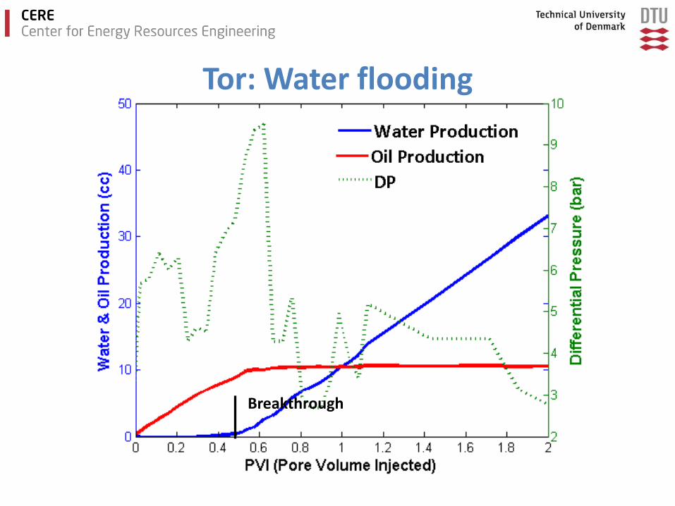
Breakthrough
Tor: Water flooding

Tor: Gas flooding

Tor: Gas flooding

Ekofisk: Water flooding

Ekofisk: Gas flooding

Ekofisk: Gas flooding

Major Flooding Results
Formation Tor Ekofisk
Porosity 26 % 33 %
Gas perm 1.1 mD 0.73 mD
So, start of waterflood 0.64 0.65
So, end waterflood 0.10 0.43
So, end CO2-flood 0.018 0.15
Sg, end CO2-flood 0.57 0.58
Produced oil, waterflood 84 %OOIP 34 %OOIP
Produced oil, CO2-flood 13 %OOIP 44 %OOIP
Residual oil, end CO2 flood 2.8 %OOIP 22 %OOIP

CO2 EOR experiments on chalk
at reservoir conditions
GEUS
Purpose of the work:
• To test the performance of CO2 injection to
produce additional oil from Syd Arne chalk after
water-flooding.
• Perform two experiments with water-flooding
followed by CO2-flooding on Syd Arne chalk.

Implications for CO2 EOR on chalk
extrapolated from work on two samples
• CO2-injection may produce significant amounts of additional oil from low-permeable chalk, even after a water-flooding operation.
• CO2-injection may result in effective oil displacementwithout early breakthrough of CO2.
• Adverse effects from dissolution and compaction werenot observed.
• CO2-injection may have a considerable potential for producing additional oil from Ekofisk chalk wherewaterflooding is inefficient.

EOR through CO2 Utilization
• Question to be answered:
– Is there a potential for CO2 EOR in Denmark usingCO2 from Danish sources?
• Answer:
– YES! and perhaps…
• A comprehensive, coordinated and carefulresearch project leading to new and solid conclusions

o No negative effect on borehole stability and compaction
o Some effect on stiffness of the Tor formation
o No negative interaction with the South Arne oil
o New generic data and modelling on CO2+brine
o Increased recovery from the Tor formation
o Dramatically increased recovery from the Ekofiskformation
EOR through CO2 Utilization

Inlet end of samples after CO2-flooding
Inlet end of sample FS-1
No dissolution features
Inlet end FS-1 before CO2-flooding Inlet end FS-1 after CO2-flooding
Inlet end sample OCD1 after flooding with
CO2-enriched water
All samples:
Diameter = 37 mm
Inlet end FS-2 after CO2-flooding