Embed Size (px)
Citation preview

Restriction/Classification Cancelled
https://ntrs.nasa.gov/search.jsp?R=20090026344 2018-06-23T09:51:40+00:00Z

IASM@~ W A RM No, ESH20
I?.ATIOT.~L ADVISORY COIQ4ITTEE FOR AERONAUTICS
RESEARCH MXMORAMDUM
for the
Air Materiel Command, Army Air Forces
INVXSTIGATION OF THEEE IjESIGN MODIFICATIONS OF THE
NACA INJECTION IMPELLEI3 IN AN R-3350 EIVGI'MC
By Robert 0, Hickel and Donald J. Michel
An investigation was conducted to determine the effects of three design modifications of the original NACA injection impeller on the performance of an R-3350 engine. Different methods of in- jecting the fuel into tlie impeller air stream were studied and evaluated from the individ~~al cylinder fuel-air ratios aad the resulting cylinder tercperatures. Each impeller was tested for a range of engine powers normally used in flight operation.
The relatively simple design of the original injection impeller produced approximately the same mixture- and temperature-distribution characteristics as the modified impellers of more complex design. None of the modifications appreciably affected the manifold pressure, the combustion-air flow, nor the throttle angle required to maintain a given engine power,
INTRODUCTION
A general investigation of means of improving the cooling of the R-3350 engine was conducted at the NACA Cleveland laboratory at the request of the Air Materiel Command, Army Air Forces. Definite cooiing improvemeats can be obtained by an im]?rovement in the fuel distribution frm. the use of the NACA inJection impeller in place of a standard nozzle bar. (See reference 1,) The hydraulic charac- teristics of several impeller fuel-injection passage designs were investigated and the results were reported in reference 2, Bench tests showed that these passages provided sufficient flow capacity without appreciable leakage at the collector cup.

NACA fiM No, E6H20 2
A full-scale engIne teat-stand inveljtigat'lon of LWae design modifications of the original injection impeller described in ref- erence 'l. was made to determine if improvement over the lnilrture distribution obtained with the original injection inspeller could be realized by use of a modified impeller and to determine the effect of each imgeller mdification on the fuel-air ratio and temperature distribution of the engine, Each design modification incorporated a different method of injecting the fuel into the combustion-air stream. The impeller design changes were intended to promote more thorough atomization of the fuel at the exit of the impeller fuel passage and t k ~ s proraote better fuel dispersion. Each type of injection impeller was tested for a rawe of engine speeds and powers normally used in flight operation. The effects of the orig-inal injection ircpeller and the three modifications on the mixture and tmperature distr';butions are shown by comparisons of the fuel-air ratio, the temperature of the rear spark-plug gasket and the temperature of the exhaust-valve seat for the individual cylinders.
DESCRIPTION OF NACA INJECTION IMPELLER
A sketch of the original injection impeller dsslgned for the R-3350 engine is shown in figure 1. This impeller is hereinafter designated impeller A. Metered fuel from the carburetor is supplied to the nozzle ring through two Suel-transfer tubes, The fuel is transferred fram the nozzle ring to the collector cup, which rotates at impeller speed. The fuel is pwnped through the collector cup by the action ~f the fuel inducer vanes into the impeller-transfer passages and is then pumped by centrifugal force into the fuel- distribution annulus that acts as an equalization chamber, As a result of centrifugal force, the fuel then flows through the fuel- injection passages into the air atream of the impeller, A complete description of the NACA injection bpeller is given in references 1 and 2. For all tests, a slotted nozzle ring with 24 holes and a long-wtned fuel inducer with 16 vanes were used. The nozzle ring and fuel inducer were designed (reference 2) to reduce the leakage 3f fuel upstream of the im3eller.
Iinpeller A. - The original injection impeller of reference 1 (fig, 1) incorgorates f uel-in jection passages of 1/16-inch diameter that discharge in slternate impeller air channels. The fuel- injection passages are slightly inclined from a radial position toward the advancing side of the impeller blade. The fuel passage was so Inclined that the fuel droplets would be struck and dispersed by the advanciq impeller blade.

W A RPI No, EEH20 3
Although the original injection impeller improved the mixture distribution considerably over that obtaiced with the standard car'bu.retor n~zzle-bar injection system (reference I), better atom- izatzon of the fuel at the outlet of the fuel-injection passages would lead to even better mi;rture- and temperature-distribution patterns. In an attempt to promote better dispersion of the fuel, three modifications were m d e to the fuel-injection passages of the original injection impeller and are designated impellers B, C, m d D. These modifications in~~olved no changes in the nozzle ring, the fuel inducer, the collector cup, or the im2eller-transfer passages. A schematic diagram of each of the iwpeller modifications for an R-3350 engi-ne is shown in figure 2.
'Impeller B, - The nodification of original impeller A is shown in figure 21a). Radial fuel-injection passages in each impeller air channel, of 1jl6-inch dimeter, exted from the f uel-distribution
3 annulus to a poiat about 44 inches frorn the center of the inpeller, Each of these passages is met by another l/l6-inch-diameter passage drilled in each blade at a 25' angle from the rear shroud of the impeller. This second passage decreases in size to 1/32-inch diameter to f o m an orifice before entering a diagonal fuel-discharge passa e 1 8 inch in dimeter drilled through the blade at an angle of 60'. iith this design, the fuel was intended to strike the diagonal fuel passage and disperse in a fine spray; about three- fourths of the fuel would be ejected fromthe advancing side of the blade whtle the other one-fourth would be eJected from the trailing side of the blads, Tne passages drilled frortithe rear sFxoud of the impeller v r e left open and may have permitted air to circulate through the passages. Air may also haxe circulated through the diagonai fuel passages from the high-pressure side to the low-pressure side of the blades.
Impeller C. - Iqeller C uses the same type fuel-inJection passages as original impeller A, The fuel-discharge passages, how- ever, are located in each impeller air passage rather than in alternate passages. Fuel-dispersion pins 5/64 inch high are located at the exit of the fuel passage as shown in figure ~(b). In this design the fuel was intended to impinge on the dlspersion pin and be finely dispersed and forced across the air ?assage where it would mix with the impeller air strem.
Impeller D, - Lnlpeller D incorporates radial fuel-injection passages, which discharge in the blades as in impeller B. These passages, however, were drilled into alternate blades rather than in every blade, Eaclz radial passage is met by a 1/16-inch-diameter passage drilled from the rear of the impeller at a 75' angle, as sliown in figure 2(c), Two 0,010-inch-diameter orifices were drilled
XACA RM No. E6H2C 4
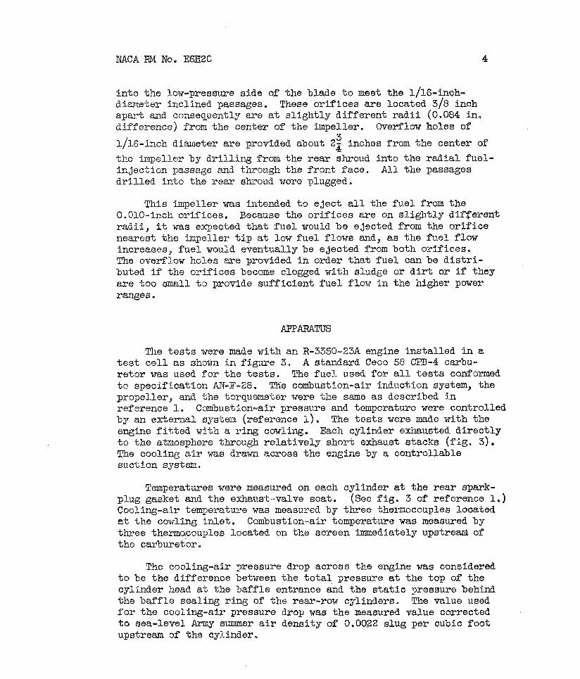
in to the low-pressure side of the blade t o meet the 1/16-inch- d i m e t e r inclined passages. These o r i f i ces a re located 3/8 inch apayt and consequentlp a re at s l igh t ly d i f fe rent r a d i i (0.084 in , difference) Tram the center of tne impeller. Overflow holes of
1/16-inch d i u e t e r a re provided about 2; inches from the center of
the iinpeller by d r i l l i n g from the r ea r shroud into the r ad ia l fuel- inject ion passage and through the f r m t face, A l l the passages d r l l l ed into the r ea r shroud were plugged,
This l i n ~ e l l e r was intended t o e jec t a l l the f u e l from the 0.010-inch or if ices . Because the or i f ices a re on s l igh t ly different r a d i i , it was emected tha t f u e l would be ejected from the o r i f i ce nearest the impeller t i p a t low fue l flows and, as the fue l flow increases, f u e l would eventually 3e ejected from both or i f ices . The overflow holes a re provided i n order t h a t f u e l can be d i s t r i - buted if the or i f ices become clogged with sludge or d i r t or i f they a r e too small t:, provide suf f ic ien t fue l flow i n the higher power ranges,
The t e s t s were made with an R-3350-23A engine instal led in a t e s t c e l l as shown i n f igure 3. A standard Ceco 58 CPB-4 carbu- r e to r was used f o r the t e s t s . The fuel used f o r a l l t e s t s confomd t o specification AN-F-28. Tkie combustion-air induction system, the propeller, and the torquemeter were the same a s described in reference 1, Combustion-air pressi~.re and temperature were controlled by an exter,.ial s~istein (ref ercnce 1 ) , The t e s t s were made with the engine f i t t e d with a r ing cowling. Each cylinder exhausted d i r ec t ly t o the atmosphere throu.gh r e l a t ive ly short exhaust stacks ( f ig . 3). The cooling a-ir was drawn across the e,xine by a controllable suction system
Temperatures were measured on each cylinder at the rear spark- plug gasket and the exha~~st--valve seat. (see f i g , 3 of reference 1.) Cooling-air tem~eratu.re was measured by three themnocouples located at the coxling In le t . Combustion-air temperature was measured 3y three thema~couples located on the screen imme6iately upstreard of the carburetor.
The cooling-air pressure drop across the engine was considered t o be the difference between the t o t a l pressure at the top of the cyl-inder head a t the bafCfle entrance and the s t a t i c pressure behind the baf f le sealing r ing of %he rear-row cjrlinders. The value used f o r the cooling-air pressure drop was the measured value corrected t o sea-level Army sLmer a i r density of 0.0022 slug per cubic foot upstream of the cylinder.

NACA :To, EGHZO 5
In 'the t e s t s of impellers A and D, the fuel-air r a t i o s of the individual cylinders were detel-nined by the use of the NACA mixture analyzer. Th-is analyzer operates on the carbon-dioxide content of oxidized e x h a ~ ~ s t gases and uses a thermal-conductivity bridge by allowing the oxidized gases t o pass over the two c e l l s of a Wheat- s t m e bridge while the other two c e l l s hold a gas of constant thermal co;xductivity. The unbalance is t5en indicated on a millivoltmeter calibrated by Orsat analysis of oxidized exhaust gases. For iilllsellers B a3d C the fue l -a i r r a t i o s of the individual cylinders were deterimi_nec? by Orsat analysis. Periodic surveys were made f o r each cylinder t o determine the oxy~en d i lu t ion of the exhaust-gas samples due t o a i r leakage in to the exhaust skack from the atmosphere. The individual fue l -a i r r a t i o s were then corrected f o r any oxygen dilution. No d l lu t ion was found b e l ~ w 1600 brake horsepower and the greatest d i lu t ion f o r a given cylinder was 2.0 gercent oxygen a t 2000 brake horsepower, which gave a correction fac tor of 1.084 f o r the fue l -a i r r a t i o of tha t par t icular cylinder.
The absolute m i f o l d pressure was measured a% the standard engine location in the intake manifold. The carburetor-deck pressure w a s masured by a s t a t i c tribe at the upper carburetor deck. The charge-air flow was calculated from lrzeasureinent of the venturi suction d i f f e ren t i a l pressure and reference t o an air-flow cal ibrat ion curve of the carburetor, The t h r o t t l e ar@e was azeasured 39 a calibrated posit ion indicator. The f u e l flow t o the engine was measured By ro tme te r s ,
TEST PROCEDURE
In order t o compare the e f fec ts of the injection-impeller mod.ification on the perfornance of the engine, similar t e s t s were made f o r each type of impeller a t f i v e powers and speeds tha t a re l i ke ly t o be used i n normal-flight operation.
Because of the influence of f u e l - a i r - r a t i ~ d is t r ibut ion on temperature d is t r ibut ion and engine performance, the e f fec ts of each inject ion impeller nodificatlon were evaluated by comparing.the patterns of fuc l -a i r r a t i o and temperature distribution, the mzni- fold pressure, the combustion-air flow, and the carburetor t h r o t t l e angle a t a given engine power. The f o l l o w i r ~ engine conditions were selected f o r each t e s t :

NACA RM No, E6E20
For all tests, the carburetor deck teazerature was maintained 0 at 100 F and the deck pressure at atmospheric pyessure. The cooling-
air pressure drop was selected to maintain the tex2erature of tke rear spark-plug gasket of t3e hottest cylinder at appr3ximately 450" F for the tests of iapeller A. Tests of the modified impellers were then rtm at the sane pressure drops. Because of variations in the cooling-air te~perature between tests, all cyliilder temperatures were corrected for a cooling-air temperature of 53' F, a aean value of the cooling-air temperatures, by the method presented in reference
Sfiortly after the rated-power test of -Zmpeller C, the engine failed. The failure occurred when two of the iznpeller-shaft oil-seal rings broke and damaged the hpell-er tip but left the fuel passages unGamaged. Consequently, the patterns of fuel-air ratio and tempera- ture were probably mly slightly affected by this failure.
Fuel-air-ratio distribu.tionA - The distribution patterns of fuel- air ratio for impellers A, B, and C, are shown in figure 4. (NO data are given for inpeller D because the design 03 jective was not realized. ) The differences be-heen the maximum and minimtm f uel-air ratio (fuel- air-ratio spread) for each impeller are given in the following table:
. . Engine 1 Fuel-air-ratio spread

NACA RM No. E6H20 7
The fuel-alr-ratio spreads at a given power were approximately the same for every impeller tested, The uzax~hwn difference in spread for all the impellers at any one power was 0.005, Tmpeller A produced fuel-air-ratio patterns that had the most consistent spreads with a cha,.lge in power; the spread varied from 0,009 to 0.011 with ckanges in engine power.
Impellers A, B, a d C produced patteims that were similar throughout the range of powers tested (fig, 4). The cylinders that were leaner than the average over-all engine fuel-air ratio were usually cylfnders 1 to LO, (the right side of the engine as viewed from the rear) whereas tile cylinders richer than the average fuel- air ratio were cylinders il to 18 (the left side of the engine). No systematic change in the fu.el-air-ratio pa5tex-n occurcred with changes in power for impellers A, B, and C .
When impeller D was rem~ved from the engine inmediately following the tests, it was found that most of the 0.010-inch-diameter orifices were so plugged by sludge or dirt that no fuel flowed through these holes. This clogging caused fuel to flow f r m the overflow holes provided near the impelisr hub and may have caased a noauniformity of dispersion of fuel in the impeller air streams. Because of this condition, the fuel-sip-ra.tio pattern exhibifed a marked change from that produced by the other im-pellers with cylinders 1 to 10 generally operating richer and the cylinders 11. to 18 operating leaner than "ce average engine fuel-air ratio, a complete reversal of the pattern produced by the previous ii~~pellers, Im2eller D was considered unsatisfactory and no data are prese~lted becau-se, with ordinary precautions taken to insure dirt-free fael, the orifices becme clogged and consequently the design objective was not accomplished.
The original injection impeller A, of relatively sim~le design, prodv.ced results that were as good or better than those of the modified tapellere of more c ~ m ~ l e x designs. Design factors that critically affect the fuel-distribution ch?.racteristics of the injection impeller appear unlilcely provided that no fuel-Injection passages clog with sludge or dirt.
Temperature distribution, - The tem2erature patterns for the rear sparlc-plug gasket and exhaust-valve seat are shown in figures 5 and 6, respectively. Bpellers A, By and C ~roduced temperature spreads of the rear spark-plug gasket that varied from a minimum of 60' F to a maximm of 93' F. The spread for e.&aust-valve seat varied from 115' F to 186' F. The temperature spreads of the rear spark-plug gasket and exhaust-valve seat are shown in the following table for each impeller:

NACA RM No. E6H20 8
The original impeller A produced temp3raturs spreads tha t were most 0
consistent with a change of power with a vartatfcn of only 5 F fo r the rear spark-plug gasket and 16' F f o r tbs e-&av.!lst-valve seat. No systematic cilange i n tenqperature patteEi cccur-sd with chariges i n power. Tlie teqiierature patterns for ililpsllers A , B, and C there- fore showed spreads and trends silnilar t o those produced by the fuel -a i r r a t i o la t terns , Iiq13eLlers B and C poduced no inportant improvemelit i n temperature pattern over imp l l e r A.
General engine ve?-formance. - The e n g j ~ e psrfomance chzrac- - - - - - * _ _ - --
t e r i s t i c s of the various impellers were e-tialuated by ~ ~ ~ ~ p a r i n g the required manif old pressure, t119 combust5 cn--air z'lov, axxi the th ro t t l e angle for each 2ower co~d i t i on , In gsneral, a l l impellers presented tlie sane performance characteristics. Because of the small differences i n over-all performance of the -~arious impeller designs, impeller A would protably be most L?esj.r8ble iassmuch as the more complex fuel discharge-passage de,signa gave no significant improvement.
SUIWIARY 03' RESULTS
The resul ts of test ing the original inJection impeller and three modifications of thfs 4esign iii an 3-3550 eugine may be summarized a s follows:
1. The relat ively simple d-esign of the original injection inpeller produced fuel-air-rat io patterns that wsre equal t o or be t ter than those produced by the modified impellers of more complex design.

NACA PIK no. E6320 9
2. The original inJection inpeller produced temperature pattern as good as those produced by the modified impellers.
3, Each impeller showed approximately the same engine perform- ance characteristics such as required lnanifold pressure, combustion- air flow, and thottle angle for a given power.
Aircraft Engine Research Laboratory, Natlonal Advisory Committee for Aeronautics,
Cleveland, Ohio.
Robert 0. Hickel, Mechanical Engineer.
Donald J, ~ichel,
g- - + L Mechanical Engineer. Approved :
Frank. E, Marble, Aeronautical Engineer.
p i ! Oscar W. Sche ,
Mechanical ~ n ~ ~ n & r .
JMarble, Frank E., Ritter, 1 K., and Miller, Mahlon A.: Effect of the NACA Injection Impeller on the Mixture Distribution of a Double-Row Radial Aircraft Engine. NACA TN No, 1069, 1946.
d Ritter, William I., Johnsen, Irving A., and lieblein, Seymour : 1' Hydraulic Characteristics of the W A Injection Impeller. I'WCA , r.
r' , 4'
$ MR No, E6C25, Army Air Forces, 1946.
&/sohey, Oscar W., Pinkel, Benjamin, and Ellerbrock, H e m H., Jr . : Correction of Temperatures of Air-Cooled Engine Cylinders For Variation in Engine and Cooling Conditions. NACA Rep. No. 645, 1938.

NACA RM No. E6C.920
MAT 8 M B k AlOV ~ S & V COMBPThE FOR AEBPOWAW ICS
F i g u r e I . - O r i g i n a l N A C A i n j e c t i o n i m p e l l e r A d e s i g n e d f o r i n s t a l l a t i o n on R-3350 e n g i n e .

4 U A V I W A L ADVISORY CW1VTF.E FOR AEROhlAUVtCS
Figure 2, - Sehematle d i a g r a m s s f m a d i f l e d , d e i s l ~ g g a s o f N A C A 8 n J e c t % o n i m p e l l e a a$ i n s t a l l e d Bn R-3350 e n g ! we,
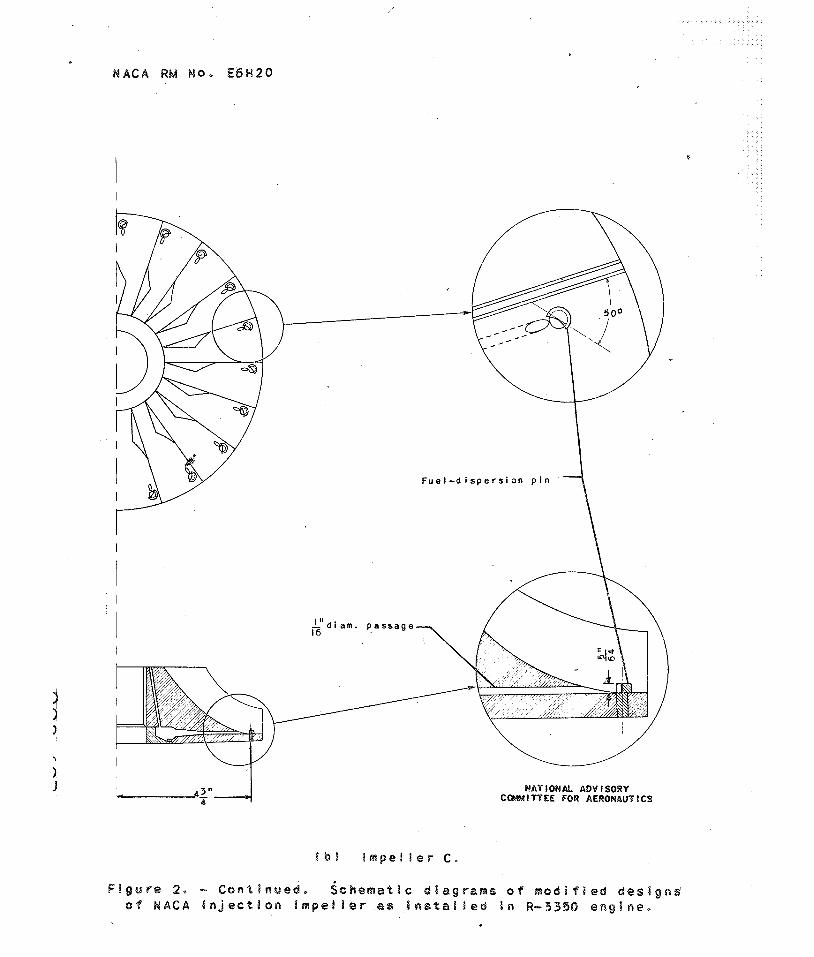
WRTlONAL ADYISOWY C W I T T E E FOR AEWONAUTOCS
F i g u r e 2 , - C o n t i n u e d . $chema%!c d i e g r a m s s f m o d i f f e d d e s i g n $ 0 4 H A C A injes%lsn i m p e l I Q ~ as i n s t a l !ed i n R-3330 e n g i n e ,

MAT l OW& ADV I SDWY CWYITTLE FOR APWOPdAUTlCS
F i g u r e 2 . - Concluded, SeRema%ic d i a g r a m s f m o d i f i e d d e s i g n o f N A C A IaJection BmpeiBer a s i n s t a b l e d $ a a R-3350 engine,
J

F i g u r e 3 - T e s t - c e I I i n s t a l I a t i o n o f R - 3 3 5 0 - 2 J A e n g i n e .

N A C A R M NO. E 4 H 2 0
R e a r row 1 3 5 7 9 1 1 13 I 5 17 F r o n t row 2 4 6 8 10 12 14 16 I8
Cy 1 i n d e r
( a ) I m p e l l e r A .
F i g u r e 4 . - F u e l - a i r r a t i o d i s t r i b u t i o n p a t t e r n s o b t a i n e d u s i n g N A C A i n j e c t i o n i m p e l l e r : i n R-3350 e n g i n e ,

N A C A RM N o * E6H20
F i g u r e 4. - - ~ o n t i nued . F u e l - a i r r a t i d d i s t r i b u t i o n p a t t e r n s o b t a i n e d u s i n g N A C A i n j e c t i o n i m p e l l e r s i n R-3350 e n g i n e ,

N A C A R M Pis. E 6 H 2 0
Rear F r o n
F i g U
( c ) I m p e l l e r C . u r e 4 . - Conc luded. Fue l -a i r r a t i o d i s t r i b u t i o n p a t t e r n s o b t a i n e d s i n g M A C A i n j e c t i o n i m p e l l e r s i n R-3350 eng ine ,
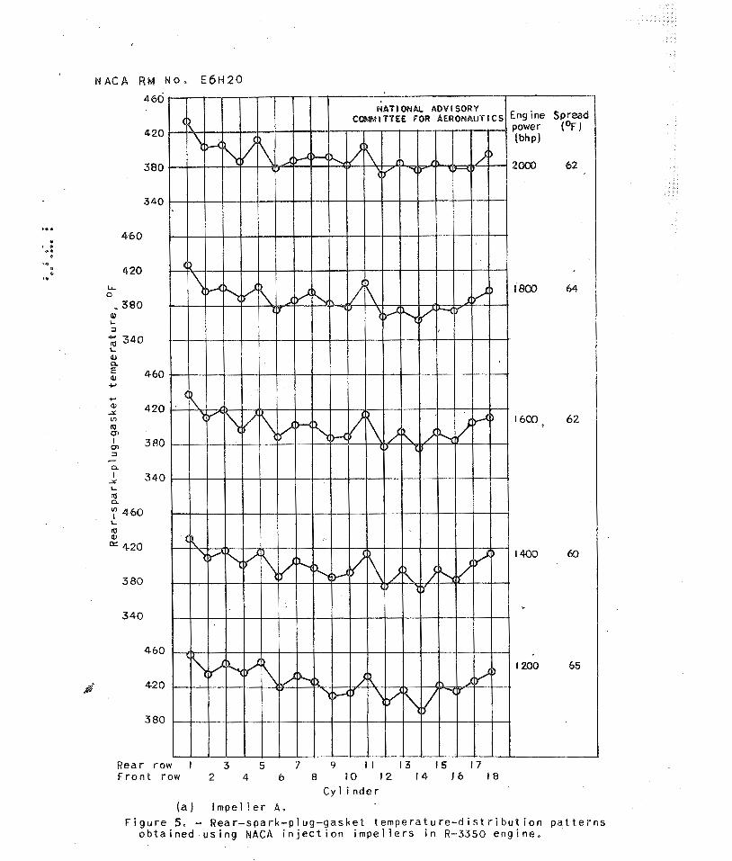
F i g u r e 5, - Rea r - spa rk -p l ug -gaske t t e m p e r a t u r e - d i s t r i b u t i o n p a t t e r n s o b t a i n e d u s i n g N A C A i n j e c t i o n i m p e l l e r s i n R-3350 e n g i n e .

N A C A R M No. E4H.20
F r o n t row 2 4 6 8 10 12 14 16 18 ~ y 1 i n d e r
F i g u r e 5. - C o n t i n u e d . ear-spark~p~u~-~asket t e m p e r a t u r e - d i s t r i b u t i o n p a f t a r n s o b t a i n e d u s i n g NACA i n j e c t i o n impel l e r s i n R-3350 e n g i n e ,

N A C A RM N O . E 6 H 2 0
F i g u r e 5. - ~ o n c ? uded. Rear -spark -p l ug-gasket t e m p e r a t u r e - d i s t r i b u t i o n p a t t e r n s o b t a i n e d u s i n g NACA i n j e c t i o n i b p e l l e r i n R-3350 e n g i n e .

M A C A RM N O . E 6 H 2 0
N A Y l ONAL ADV l SORY
CY I lnder
( a ) Impel le r A . F ~ g u r e 6. - Exhaust-valve-seat t e m ~ e r a t u r e - d l s t r i b u t l o n Pat terns obtalned using NACA l n ~ e c t l o n impellers ~n
R-33SO eng one.

N A f l ONAL ADV l SORY
C y l ~ n d e r
( b ) I m p e l l e r B . F ~ g u r e 6. Continued. Exhaust-valve-seat temperature -d ls t r lbut lon p a t t e r n s o b t a ~ n e d u s l n g NACA l n j e c t l o n f m p e l l e r s i n
R-3350 e n g l n e .

N A C A R M N O . E6H20
Cy l ~ n d e r
LC) Impel le r C. Figure 8. - Concluded. Exhaust-valve-seat temverature-dlstrlbution pat terns o b t a ~ n e d using NACA l n j e c t ~ o n bmpel I
I n R-3350 engine.