Embed Size (px)
Citation preview
HAL Id: tel-01368098https://tel.archives-ouvertes.fr/tel-01368098
Submitted on 19 Sep 2016
HAL is a multi-disciplinary open accessarchive for the deposit and dissemination of sci-entific research documents, whether they are pub-lished or not. The documents may come fromteaching and research institutions in France orabroad, or from public or private research centers.
L’archive ouverte pluridisciplinaire HAL, estdestinée au dépôt et à la diffusion de documentsscientifiques de niveau recherche, publiés ou non,émanant des établissements d’enseignement et derecherche français ou étrangers, des laboratoirespublics ou privés.
New generation of network access controller : an SDNapproach
Benjamin Villain
To cite this version:Benjamin Villain. New generation of network access controller : an SDN approach. Networking andInternet Architecture [cs.NI]. Université Pierre et Marie Curie - Paris VI, 2015. English. �NNT :2015PA066663�. �tel-01368098�
THÈSE DE DOCTORAT DEl’UNIVERSITÉ PIERRE ET MARIE CURIE
Spécialité
Informatique
École doctorale Informatique, Télécommunications et Électronique (Paris)
Présentée par
Benjamin Villain
Pour obtenir le grade de
DOCTEUR de l’UNIVERSITÉ PIERRE ET MARIE CURIE
Sujet de la thèse :
Nouvelle génération de contrôleur d’accèsréseau : une approche par réseaux logiciels
soutenue le 09 octobre 2015
devant le jury composé de :
Dr. Lila Boukhatem Rapporteur, Université Paris-Sud, Orsay, FranceDr. Nicolas Normand Rapporteur, Université de Nantes, Nantes, FrancePr. Jean-Louis Rougier Examinateur, Télécom ParisTech, Paris, FranceDr. Marcelo Dias de Amorim Examinateur, UPMC (Paris 6), Paris, FranceDr. Julien Ridoux Examinateur, Synclab, AustraliePr. Khaldoun Al Agha Examinateur, Green Communications, Paris, FrancePr. Guy Pujolle Directeur de thèse, UPMC (Paris 6), Paris, FranceDr. Patrick Borras Co-directeur de thèse, Ucopia, Montrouge, France

Cette thèse est dédiée à mon grand père.
Remerciements
Je tiens à remercier toutes les personnes qui de part leur temps, leur
expertise et leur sympathie ont permis l’aboutissement de cette thèse. En
premier lieu je souhaite adresser à M. Guy Pujolle mais plus sincères re-
merciements pour m’avoir accueilli au sein de son équipe et guidé tout au
long de mon parcours. En second lieu je tiens a remercier chaleureusement
Julien Ridoux qui, bien qu’extérieur au projet, a contribué en permanence
à améliorer mon travail en apportant un regard lumineux et très critique
sur tout ce que j’ai entrepris.
Merci à la société Ucopia de m’avoir accueilli durant ces trois années
et de m’avoir donner les moyens nécessaires à l’accomplissement de cette
thèse. Je souhaite remercier toutes les personnes avec qui j’ai pu travailler :
Olivier, Jérémy, Felix, Philippe, Julien, Nicolas, Badis, Ousmane, Kodjovi
et tous les autres.
Je remercie les membres du jury, Marcelo Dias de Amorim, Jean-Louis
Rougier, Khaldoun Al Agha et Patric Borras d’avoir accepté de sacrifier
une partie de leur temps pour juger mon travail et en particulier les deux
rapporteurs, Lila Boukhatem et Nicolas Normand qui m’ont permis de part
leurs rapports détaillés et constructifs d’améliorer mon manuscrit.
Enfin je souhaite remercier l’ensemble de mes proches pour toute l’aide
morale et logistique qu’ils m’ont apportées. Mes parents ainsi que mon
beau-père dans un premier lieu qui ont toujours fait en sorte que je puisse
étudier et travailler dans les meilleurs conditions possible. Juliette Guéry
qui m’a supportée tout au long de ces trois années et qui m’a apportée
le soutien quotidien nécessaire à l’accomplissement de mon travail. Pour
finir je tiens a remercier l’ensemble de mes sœurs et en particulier Lucile,
Judith, Roxanne et Clara qui ont construit mon esprit et me permettent
de m’enrichir chaque jour.

Abstract
This dissertation presents the importance of cross-layer network infor-
mation for network applications in the context of network access control.
After describing the ins and outs of network access control and its cru-
cial needs of cross-layer data, the dissertation exposes a novel architecture
in which a network access controller is mutualized in the Cloud. This ar-
chitecture allows to address a key market segment for clients unwilling to
buy expensive hardware to control their network. Multiple challenges come
into play when hosting the controller remotely. Indeed cross-layer informa-
tion are no longer available which prevents the controller from correctly
controlling users activity.
A first implementation to share cross-layer information is presented in
chapter 2. It leverages specialized session border controllers to send these
data in the application protocol, here HTTP. Then chapter 3 presents an
innovative solution for the cross-layering problem which allows to intru-
mentalize network flows with SDN protocols. The solution focuses on a
web portal redirection but is extendable to any kind of protocols. The
implementation permits to intercept and modify flows in order to input
cross-layer data within another network protocol. This solution was imple-
mented in the OpenDaylight OpenFlow controller and shows great results.
The mutualized approach coupled with the SDN cross-layer framework
allow to build flexible networks with almost no configuration of on-site
equipments. The central network controller reduces the overal cost of the
solution by being mutualized among multiple clients. Moreover, having the
ability to intrumentalize network traffic in software allows to implement
any kind of custom behavior on the runtime.

Contents
Introduction 9
1 Access control in private networks 15
1.1 Authentication . . . . . . . . . . . . . . . . . . . . . . . . . 16
1.1.1 Identity management . . . . . . . . . . . . . . . . . . 18
1.1.2 Password . . . . . . . . . . . . . . . . . . . . . . . . 18
1.1.3 Asymmetric cryptographic keys . . . . . . . . . . . . 22
1.1.4 Digital certificate . . . . . . . . . . . . . . . . . . . . 24
1.1.5 SIM . . . . . . . . . . . . . . . . . . . . . . . . . . . 26
1.1.6 Summary . . . . . . . . . . . . . . . . . . . . . . . . 28
1.2 Authentication protocols for access control . . . . . . . . . . 29
1.2.1 Device to access network . . . . . . . . . . . . . . . . 29
1.2.2 Authenticator to authentication server . . . . . . . . 35
1.2.3 Summary . . . . . . . . . . . . . . . . . . . . . . . . 40
1.3 Flow control . . . . . . . . . . . . . . . . . . . . . . . . . . . 41
1.3.1 Hierarchy of protocols . . . . . . . . . . . . . . . . . 41
1.3.2 Basic firewalling . . . . . . . . . . . . . . . . . . . . . 43
1.3.3 Deep packet inspection . . . . . . . . . . . . . . . . . 44
1.3.4 URLs filtering . . . . . . . . . . . . . . . . . . . . . . 45
1.3.5 Lawful obligation . . . . . . . . . . . . . . . . . . . . 47
1.4 Summary . . . . . . . . . . . . . . . . . . . . . . . . . . . . 48
2 A mutualized approach 51
2.1 Motivations . . . . . . . . . . . . . . . . . . . . . . . . . . . 52
2.2 Proposed architecture . . . . . . . . . . . . . . . . . . . . . . 53
2.2.1 Local equipment . . . . . . . . . . . . . . . . . . . . 55
2.2.2 Remote controller . . . . . . . . . . . . . . . . . . . . 56
2.2.3 Technical challenges . . . . . . . . . . . . . . . . . . 58
2.3 Controller side implementation . . . . . . . . . . . . . . . . 59

8 Contents
2.3.1 Adapting to each vendor . . . . . . . . . . . . . . . . 60
2.3.2 Improving user experience and data gathering . . . . 62
2.4 Summary . . . . . . . . . . . . . . . . . . . . . . . . . . . . 62
3 An SDN approach 67
3.1 Discussion . . . . . . . . . . . . . . . . . . . . . . . . . . . . 68
3.2 OpenFlow . . . . . . . . . . . . . . . . . . . . . . . . . . . . 69
3.2.1 Protocol overview . . . . . . . . . . . . . . . . . . . . 70
3.2.2 Packet matching . . . . . . . . . . . . . . . . . . . . 71
3.2.3 Limitations . . . . . . . . . . . . . . . . . . . . . . . 72
3.3 Proposal to overcome OpenFlow limitations . . . . . . . . . 73
3.4 OpenFlow network tunnel . . . . . . . . . . . . . . . . . . . 75
3.4.1 TCP analysis . . . . . . . . . . . . . . . . . . . . . . 76
3.4.2 Packets handling . . . . . . . . . . . . . . . . . . . . 79
3.4.3 Performance measurements . . . . . . . . . . . . . . 81
3.5 Captive portal implementation . . . . . . . . . . . . . . . . . 83
3.5.1 Traffic redirection . . . . . . . . . . . . . . . . . . . . 83
3.5.2 Web server . . . . . . . . . . . . . . . . . . . . . . . 85
3.5.3 OpenFlow controller . . . . . . . . . . . . . . . . . . 85
3.5.4 Dealing with TCP . . . . . . . . . . . . . . . . . . . 86
3.5.5 Performance . . . . . . . . . . . . . . . . . . . . . . . 88
3.5.6 Summary . . . . . . . . . . . . . . . . . . . . . . . . 90
Conclusion and Perspectives 95
A Dealing with over sized packets 99
List of Figures 101
List of Tables 103
Bibliography 105
Introduction
Network applications are built on top of protocols to transmit informa-
tion between multiple entities. IP address, MAC address, port numbers
are examples of valuable information transiting on the network which al-
low pieces of software to take decisions: "where to forward a packet ?",
"which application to send data to ?". But information retrieved from a
single layer might not be suffisiant for applications, especially when they
implement custom behavior. Routing decisions based on signal strength in
wireless mesh networks [22] [21] [18] [10], handover [39] [29], link failure
detection [61] or QoS in mesh networks [74] are examples of applications
which require cross-layer information in order to correctly take decisions.
While these subjects have a number of related contributions, little con-
crete implementations exist. Indeed they require the modification of crit-
ical pieces of an Operating System’s core, the Network Stack. Despite
being critical, the Network Stack is also a complex piece of code because it
implements complicated protocols. Additionally, custom implementations
introduce compatibility issues between various systems making concrete
deployements even harder.
This thesis tries to bring a new angle to the cross-layering problem
using Software Defined Networking protocols. Leveraging the capacity
of such protocols to externalize network topology information, a generic
cross-layering framework can be implemented. For industrial reasons, this
presentation focuses on Network Access Control applications which map
a user identity with a network device. Such applications extensively use
cross-layer information, from the physical layer to the application layer to
identify a device, filter its traffic or even build custom routing tables. The
present work aims at providing a system which share cross-layer informa-
tion with remote actors in order to provide Cloud-based Network Access
Controllers.
Over the past ten years, the quality of service provided by Internet
10 Introduction
access vendor has been greatly enhanced. The deployment of high-speed
ADSL [25] links and optical fibers played a key role at bringing high speed
bandwidth Internet access [38] to everyone. In the mean time, the physical
access network moved from wired to wireless links [55] [58] and devices are
now mobile. Laptops, smartphones or tablets are examples of the trend in
the hardware market. Users now have the capacity to associate with foreign
Wi-Fi networks easily. Moreover, thanks to the links capacity increase, an
Internet access can be shared with multiple users with no noticeable effect.
Helped by the growth of the Wi-Fi industry, the number of public
opened networks, known as hotspots, has reached a point where it is possi-
ble in many city inside Europe or the United-States to gain Internet access
free of charge. Restaurants, hotels, public venues or even public transport
are offering Wi-Fi connectivity to their guests, sometimes in exchange for
personal information. Internet providers leverage the homenet boxes setup
in every home to provide their own hotspot available for their clients only.
On the other hand, opening a network to guest users brings all kinds of
problems related to security and traceability. Security is an obvious issue
when welcoming guests as they might have access to sensitive resources
inside the private networks, eavesdrop on communications or even take
over some machines. As a result, the guest network has to be isolated
from the rest of the private network in order to protect critical resources.
Regarding traceability, governments have rapidly understood the threat of
hotspots because of the anonymity they provide to end-users. When two
users from the same Local Area Network access a server on the Internet,
it is unable to differentiate them from a network point of view. Because
private networks implement a Network Address Translation to access the
Internet, every packets emitted from the LAN share the same source. This
public address is thus shared amongst all users of the same hotspot. In
order to prevent ill-advised users from using public networks to evade the
law, many countries made the Internet access owner liable for its usage. As
a result, people and companies willing to share their Internet access need
to control their visitors: who are they ? what resources did they access
during their journey ?
A dedicated appliance is required to implement these tasks. Various
hardware solutions exist in the market, either as Wi-Fi access points or
smart gateways, but they are expensive and usually hard to setup. This
explains partially why today only companies can afford them and provide

Introduction 11
Internet hotspots.
This thesis aimed at developing a new way of thinking guest access
architectures in private networks. It intends to reduce the global cost of
the network access controller by mutualizing them among a multitude of
clients. This network access controller, hosted in the Cloud, interacts with
smart Wi-Fi access-points present on each site. Two types of smart Acccess-
Points are considered in this thesis. The first category is Wi-Fi access-
points already available on the market. They implement dedicated features
to control user access, gather cross-layer information and interact with
remote captive portals. The second category consists in implementing a
border session controller using SDN protocols. The idea is to abstract
the hardware in order to implement a generic interface between on-site
equipments and the remote controller to exchange cross-layer data.
SDN protocols, such as OpenFlow, allow a network equipment to del-
egate part of its forwarding decisions to an external controller. This gives
the opportunity to extend hardware features from controlled software. SDN
enabled equipments are rapidly growing especially regarding OpenFlow.
Hardware from core to access network including Wi-Fi access-points are
now including SDN capabilities. Even non-eligible networks can benefit
from SDN technologies thanks to regular computers. For example, the
Linux kernel is able to run software routers and switches via the Open-
VSwitch project [16] which implements some SDN features.
Given the SDN market growth, in few years the majority of network
equipments will be SDN capable. Having the ability to build session bor-
der controllers from any generic hardware presents a great opportunity to
control any network without the need of specific hardware.
The contributions presented in this document have been published in a
couple of International conferences and a European patent has been filled
after resolving the biggest technical challenge of this Ph.D.
Context
This thesis, started in 2012, is the result of the collaboration between
the LIP6 and Ucopia Communications. It is an industrial thesis combining
research subjects with industrial problematics. Ucopia is a Paris based
company created in 2002 at the UPMC. UCOPIA develops and markets
solutions enabling mobile users to achieve simple, rapid and secure Internet

12 Introduction
access on public and private Wi-Fi networks. Whether at home, at the
office, in a hotel or shopping in the street, UCOPIA delivers an outstanding
experience to the mobile users.
UCOPIA also enables business organizations deploying Wi-Fi networks
to best engage with their users, enhance loyalty and create new revenues
opportunities. With UCOPIA, hotels, stadiums and airports, shopping
malls and retail chains increase customer satisfaction and generate more
revenue. As an example, the average revenue per connected fan during the
last Super Bowl was $100.
UCOPIA solutions comprise a comprehensive combination of software,
appliance and cloud services serving small to large customers. More than
10,000 UCOPIA solutions are deployed and maintained by UCOPIA expert
partners all over the world.
The purpose of this thesis was to improve of the Ucopia solution with a
scientific approach. In the mean time, a large amount of the Ph.D has been
dedicated to develop roadmap features which required technical expertise
in various fields including network and system programming, scripting, de-
bugging, database management, HMI development and many more.
All the work presented in this document, either scientific or industrial,
has been in the vast majority done by the author of this thesis. Although
it has contributed to a wide range of other tasks, they are not in the scope
of this manuscript.
Structure of the dissertation
The present dissertation is organized around three chapters. Chapter 1
makes an in-depth coverage of network access control in private networks.
It covers user authentication methods with different types of secrets, com-
munication protocols from the user device to external user management
servers and techniques to control user network activity. This chapter aims
at giving enough background information to the reader in order to thor-
oughly understand the key points of network access control.
Chapter 2 then presents a new architecture in which the Ucopia con-
troller is hosted outside the access network. This architecture responds to
an industrial demand consisting in controlling multiple distant networks
with a unique controller. After identifying the technical locks, concrete so-
lutions implemented inside the Ucopia controller are presented. All these
Introduction 13
developments are part of the Ucopia solution since version 5.0 released
in early 2014. Projects to equip stadiums, train stations and conference
centers already benefit from this architecture.
Finally Chapter 3 presents the main contribution of this thesis: us-
ing OpenFlow equipments as session border controllers. After introducing
OpenFlow, few limitations are spotted preventing to acquire mandatory
information from Chapter 2 in the Ucopia controller. To overcome this
lock, a technical solution implementing a web redirection only using Open-
Flow equipments is presented. A patent was filed in order to protect this
invention. After dealing with some implementation details, a performance
analysis is made to ensure the implementation scales. The results demon-
strates that the prototype can handle at least thousands of users alone.
Moreover the controller can be duplicated in order to increase the overall
capacity.

Chapter 1
Access control in private
networks
During the last ten years, private networks have shifted from delivering
services to individuals belonging to the same organization, to providing
network access for occasional guests. Prior to this shift, the user population
used to be trusted: office colleagues, family, but now, strangers also use
the same infrastructure. Aliens are de facto untrusted that is why they
need special attention. Company finance records, source code or clients
databases are examples of sensitive data stored inside private networks.
Obviously, part of these data has to be available for authorized users but
the guest population has to be excluded.
An analogy can be made with a theater. The building is split into
different sections: the scene, the bleachers, the backstage. Depending on
its identity, an individual will be authorized or not to access a section of
the theater. For instance, an actor is able to go wherever he wants whereas
a spectator can only go seat in the public. The notion of “identity”is really
important because it tells the category in which the user belongs. Once
known, and shared among all security guards, each checkpoint is able to
decide whether a person is allowed to enter the area or not.
Similarly in networks, the user identity is the keystone of the security
model. Indeed, given a user profile, one can derive a set of usable network
services, grant access to specific areas of the network or even enhance qual-
ity of service. The identity recognition system has to provide a certain level
of trust depending on the criticality of the information system. For exam-
ple in real life, a military base has stronger identity checks than a movie
theater. Failing to recognize an identity theft can lead to unauthorized
16 Chapter 1. Access control in private networks
access to sensitive resources.
To sum up, the access network has to identify users when they connect,
compartmentalize itself into different zones and ensure that users are en-
titled to access them and finally authorize user network traffic based on
their allowed services: web, mail, file transfer. . . In order to verify an iden-
tity, the user has to prove it to the system. Passports and ID cards are
not easily usable for computers as they have to be scanned in order to
verify their authenticity. Moreover the identity of a network user is not
necessarily its real name and these documents provide personal informa-
tion. As a result, authentication systems use a secret held by the user,
in the form of exchangeable data: either textual (passphrase) or in binary
(cryptographic keys). The combination of a unique identifier and its se-
cret allows the system to uniquely identify a user. If the secret is secured
enough that nobody else can access it, identity theft is prevented. A com-
munication channel must also exist between each user and the recognition
system. This channel can be encrypted, providing confidentiality, or not
which could expose the secret to other users.
The goal of this chapter is to present the different notions which come
into play when securing a network. User authentication methods are first
detailed in section 1.1. Then different protocols are presented in section
1.2, they provide the communication channels permitting the transfer of
authentication data. And finally section 1.3 describes different techniques
to control user traffic on the runtime.
1.1 Authentication
A critical aspect of access control lays in the verification of users identity,
either they are human or non-human. In real-life official documents such as
passports or ID cards are commonly used to identify citizens. The security
of these documents is provided by a special footprint almost impossible
to reproduce. In computer science, authentication is widely used, from a
simple login inside a computer to a military grade mutual authentication
between two machines. It outlines different needs for different applications
in terms of security, user-friendliness and setup ease.
The general idea of user authentication is to ensure that somebody is the
one he says he is. Typically, each user is being assigned a unique identifier
which represents its identity within the system. A username or an email
1.1. Authentication 17
address are examples of identifiers used everyday. A secret is attached to
each identifier and shared with the user so the system knows, when he
provides the correct secret, it is the right person. Each user holds its own
secret and the authentication server records all the secrets for every users
in the database. Secrets might have multiple forms, either symmetric or
asymmetric. A symmetric secret is a secret that is exactly the same for the
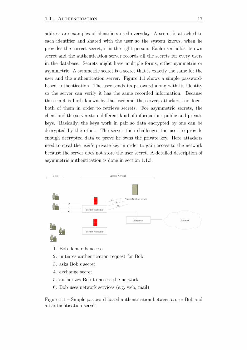
user and the authentication server. Figure 1.1 shows a simple password-
based authentication. The user sends its password along with its identity
so the server can verify it has the same recorded information. Because
the secret is both known by the user and the server, attackers can focus
both of them in order to retrieve secrets. For asymmetric secrets, the
client and the server store different kind of information: public and private
keys. Basically, the keys work in pair so data encrypted by one can be
decrypted by the other. The server then challenges the user to provide
enough decrypted data to prove he owns the private key. Here attackers
need to steal the user’s private key in order to gain access to the network
because the server does not store the user secret. A detailed description of
asymmetric authentication is done in section 1.1.3.
Border controller
Internet
Authentication server
Gateway
Border controller
1)
2)3)
4)5)
6)
Users Access Network
1. Bob demands access
2. initiates authentication request for Bob
3. asks Bob’s secret
4. exchange secret
5. authorizes Bob to access the network
6. Bob uses network services (e.g. web, mail)
Figure 1.1 – Simple password-based authentication between a user Bob andan authentication server
18 Chapter 1. Access control in private networks
This section presents the basics of authentication starting with identity
management. It then presents the main authentication schemes outlining
their benefits and drawbacks.
1.1.1 Identity management
Many applications, not only in computer science, need to identify en-
tities uniquely. For instance in France, each citizen has a unique social
security number which is used in various situations including medical acts,
tax payments and welfare. Commonly, an identity is represented by an
identifier which takes the form of a name, a label or a number. It repre-
sents in a specific context an entity of the system. This identifier can be
automatically generated, either randomly or based on concrete elements,
or chosen. Typically in computer science, many systems use a user login to
identify users. The neat aspect is that they can choose their login so they
can better remember it, as long as it is not already used by another user
of the system.
In a global system, identifiers might contain a namespace to identify
the service provider to which the login belongs. For example, let’s take
the email address [email protected]. It identifies the user john.doe
within the provider provider.com. It is separated by the @ character into
two parts: the right part is the service provider in charge of the user ac-
count, whereas the left part represents the user identifier within the service
provider’s system. To authenticate the user John Doe, one needs to route
the authentication request to provider.com authentication service. Authen-
tication routing consist in performing a user authentication on a distant
service provider, possibly with multiple authentication servers in between.
Authentication routing is a widely used technique because it allows a user
to be authenticated by its service provider from a foreign location. This
type of setups is detailed in section 1.2.2.
1.1.2 Password
The password authentication is probably the most used nowadays espe-
cially for common users. It consists of a shared secret between the user and
the authentication server. The server stores the user’s identifier along with
its password. The password can be stored in two different formats: plain
text or hashed. Storing a password in plain text is not advisable because
1.1. Authentication 19
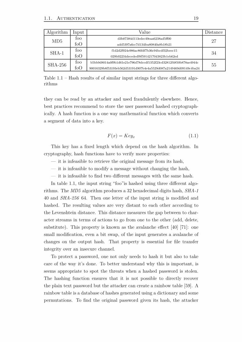
Algorithm Input Value Distance
MD5foo d3b07384d113edec49eaa6238ad5ff00
27foO add5397a6cc7d134fea80840a8b18b21
SHA-1foo f1d2d2f924e986ac86fdf7b36c94bcdf32beec15
34foO 029b92234decededf8f5914217043823b1eb62ed
SHA-256foo b5bb9d8014a0f9b1d61e21e796d78dccdf1352f23cd32812f4850b878ae4944c
55foO 90016329b8f53193eb562d53191d907b4e4a5529d087a2149469d09149c4ba24
Table 1.1 – Hash results of of similar input strings for three different algo-rithms
they can be read by an attacker and used fraudulently elsewhere. Hence,
best practices recommend to store the user password hashed cryptograph-
ically. A hash function is a one way mathematical function which converts
a segment of data into a key.
F (x) = Keyx (1.1)
This key has a fixed length which depend on the hash algorithm. In
cryptography, hash functions have to verify more properties:
— it is infeasible to retrieve the original message from its hash,
— it is infeasible to modify a message without changing the hash,
— it is infeasible to find two different messages with the same hash.
In table 1.1, the input string “foo”is hashed using three different algo-
rithms. The MD5 algorithm produces a 32 hexadecimal digits hash, SHA-1
40 and SHA-256 64. Then one letter of the input string is modified and
hashed. The resulting values are very distant to each other according to
the Levenshtein distance. This distance measures the gap between to char-
acter streams in terms of actions to go from one to the other (add, delete,
substitute). This property is known as the avalanche effect [40] [71]: one
small modification, even a bit swap, of the input generates a avalanche of
changes on the output hash. That property is essential for file transfer
integrity over an insecure channel.
To protect a password, one not only needs to hash it but also to take
care of the way it’s done. To better understand why this is important, is
seems appropriate to spot the threats when a hashed password is stolen.
The hashing function ensures that it is not possible to directly recover
the plain text password but the attacker can create a rainbow table [59]. A
rainbow table is a database of hashes generated using a dictionary and some
permutations. To find the original password given its hash, the attacker

20 Chapter 1. Access control in private networks
simply looks for the hash in its database. The lookup is very quick as the
table can be indexed by hashes to speed up queries.
In order to prevent the use of such tables, password should be hashed
with a salt. The salt is a random string concatenated to the user password
to produce the hash result. It breaks the rainbow table of an attacker as he
will have to rebuild it using the correct salt. Having one salt per password
makes the use of a pre-calculated table completely useless. Indeed, the
attacker would have to build one table per password which is equivalent
to brute forcing. Furthermore, the hashing function needs to be chosen
carefully, obviously to avoid hash collision but also to ensure it takes a
fair amount of time to generate a hash. Indeed when building a table of
millions of passwords, the time to generate each hash is really important.
The longer it takes to hash one password, the harder it is to rebuild a table.
Today’s standards advocate for the usage of the SHA-256 and SHA-512
algorithms.
After this short password storage presentation, the next paragraph ex-
plains how to verify the password between a client and a server.
Plain text
The first technique is pretty straightforward. The client sends its pass-
word to the server in plain text. The server hashes this chunk of data and
compares the hash with the one stored for the given identity. If they match,
the user is authenticated, otherwise he entered the wrong pass phrase. The
benefit of this method is that it is really simple to implement.
Few weak points must be spotted though. First of all in most situations,
the communication link is insecure: a third party can eavesdrop the data
passing by that link. This might lead to password being stolen by an
attacker. To address this issue, one can set up a secure channel between the
client and the server to prevent eavesdropping. For web communications,
HTTPS has become a popular protocol to protect the data on-the-wire.
Another solution to protect the user password would be to hash it on the
client side so it is not sent in plain text. It prevents an attacker from seeing
the real password but makes replay attacks [67] [73] possible by directly
using the hash as pass phrase.
The plain text method has the advantage of being dead simple but is
only usable through secured links. Because this kind of links are hard to
setup, other techniques have been built for instance by challenging the user
1.1. Authentication 21
in order to verify its secret without sending it in an obvious way.
Challenge
In order to prevent password leaks on insecure channels, a challenge-
response mechanism can be used. The user, instead of sending its password
directly, first initiates an authentication session with the server giving him
its identity. The server replies with a challenge that should be solved by
the client. A trivial challenge implementation would be to use the user
password but it would be as bad as the previous section scheme.
To prevent sending the plain text password, the server challenges the
client by sending a random chunk of data. It then expects a response from
the client. The response is obtained by hashing the challenge concatenated
with the user password. The server compares the response with the ex-
pected value it has computed to know if the password is correct. This
mechanism does not rely on sending the password directly to the server.
Instead it uses the hash function property which says that it is infeasible
to retrieve the original message from its hash to hide the secret.
Even though this technique prevents plain text passwords from being
sent on-the-wire, it requires the server to store them in plain text format.
Indeed to compute the expected response it has to use the real user pass-
word. A workaround uses hashed passwords instead of their plain text
form. This way, the challenge response is computed using the password’s
hash. In this situation, the hash becomes the secret, hence the password,
making the system as insecure as before.
Passwords are the simplest form of secrets in computer science. It re-
quires the users to remember a set of characters in order to authenticate
against a service. For security reasons, passwords should be hard to guess
by humans and machines but in many situations, users are known to have
weak passwords [33] [46]. Moreover they tend to re-use a password for
multiple services leading to wider compromission if it is exposed.
They are still widely used because of their implementation simplicity
and their adoption by all users. Next section presents a more robust au-
thentication scheme bringing asymmetric cryptography into play.

22 Chapter 1. Access control in private networks
1.1.3 Asymmetric cryptographic keys
Asymmetric keys, also known as public/private keys, are the strength
of many security systems. HTTPS use them to exchange the encryption
key between a client and the server, SSH on the other hand can perform a
client authentication based on its public key. Both of these examples are
based on the same property: data encrypted by a key can be decrypted
using its counterpart.
Keys are generated by a generator with a random seed:
G(seed) = (Kpriv, Kpub) (1.2)
According to their names, the private key Kpriv must be kept secret
whereas the public key Kpub can be disclosed safely to others. Given an
encryption algorithm A which takes a key and a data payload to encrypt
it and its reverse form A′ which takes a key and encrypted data to decrypt
it, the following properties exist between the two keys:
A(K, data) = C (1.3)
A′(K ′, C) = data (1.4)
Here K can be replaced by either the private or public key and K ′ by
its pair.
According to these characteristics, two scenarios can be implemented.
First if Kpub is used to encrypt a chunk of data, only the owner of Kpriv
can decrypt it. This first scenario allows for example to send encrypted
emails to a specific recipient: only the owner of the private key is able to
decrypt and read the email’s content. The second scenario uses the keys
the other way around. Data are encrypted using Kpriv so everybody can
decrypt them using Kpub. In this scenario, the owner of Kpriv can prove the
authenticity of a message: indeed if the recipient of the message is able to
decrypt it, then the message was issued by the correct sender. This second
scenario can be leveraged to implement a signature system. The goal here
is to provide a digital authenticity stamp in order for users to verify digital
documents. The private key owner checksums the document in order to
produce a hash H . He then encrypts this hash using its private key to
produce the signature S:
1.1. Authentication 23
A(Kpriv, H) = S (1.5)
This signature is appended to the document and sent. Now from a
user point of view, in order to verify the document’s authenticity, he also
checksums the document and compare it with the decrypted signature:
A′(Kpub, S) = H (1.6)
If the computed hash and the decrypted signature match, then the
document was signed by the private key’s owner. This system is used to
sign email with PGP [75] as well as in the certificate chain of trust presented
in next section.
With these use cases in mind, it becomes easy to authenticate the owner
of a public key. Here the server has a public key and wants to ensure the
user on the other end owns the corresponding private key. In order to
verify that, the server challenges the user to decrypt a chunk of random
data. These data are encrypted by the server using the user’s public key
and sent to him. In return, the client has to reply with the decrypted
message. If the response is effectively the original challenge, it proves that
the user owns the private key. To strengthen security, the operation can be
done multiple times preventing the client from guessing are re-using older
responses.
Asymmetric keys provide a safe way of authenticating users. Indeed
because the secret is never sent between the client and the server, nobody
can eavesdrop and steal from it. Moreover, asymmetric cryptography pro-
vides strong security on the encrypted messages preventing attackers to 1)
decrypt a message, 2) fake a response. But this mechanism assumes that
the server already has the user’s public key and is able to match it with an
identifier. In practice, the system uses client certificates in order to verify
the user’s identity and to retrieve its public key. This certificate along with
the key pair are usually generated by the server at user registration.
Next section details how certificate works and demonstrates how they
can be used to securely identify somebody.

24 Chapter 1. Access control in private networks
1.1.4 Digital certificate
Previous section introduced the concept of asymmetric cryptography
to securely authenticate a user. Still it assumed that the server and the
client trust each other and know each other’s keys. In real life such as-
sumption can not be made and another mechanism must be added: digital
certificates.
A certificate is an electronic document which contains information about
a public key, its owner and a digital signature of an entity who has verified
the certificate’s content. The signer, called the Certificate Authority must
be trusted by entities working with the certificates, here clients and the
authentication server. To authenticate a user, one must verify that he
owns the private key which is attached to the certificate’s public key. This
is easily implemented using the properties presented in last section.
The server must also have a certificate in order to ensure clients belong
to the domain. Indeed it verifies that the client certificate was signed by the
same CA as his certificate to tell if they are from the same infrastructure.
If the verification fails, the user can not be authenticated. Hence care
must be taken about the CA which signed the server certificate. Indeed
if it is a public authority, all certificates signed by it will be valid for the
server. In the context of a private network, it is an error to proceed this
way because public authorities sign millions of certificates for thousands
of entities. Rather the administrator should create a private CA which in
turn signs every certificates created both for clients and the server. This
way he can control the certificates he creates.
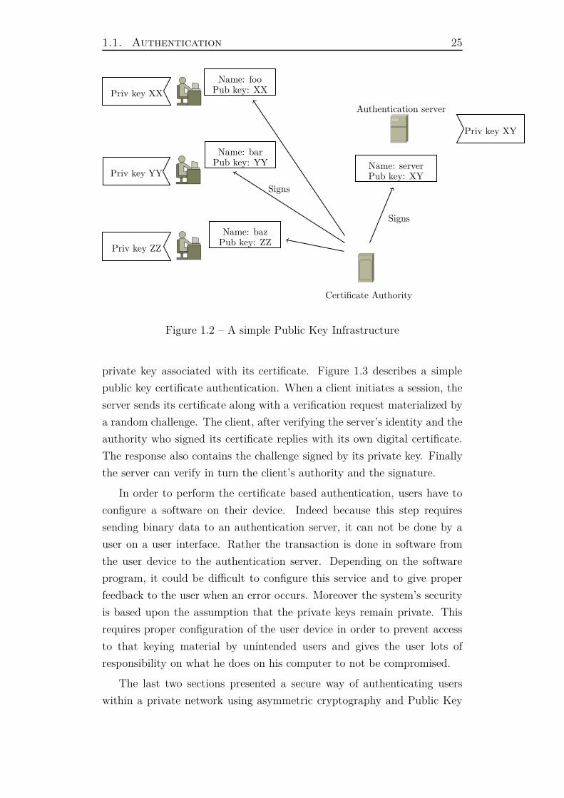
Last paragraph described Public Key Infrastructure. This system is
in charge of creating, storing and distributing digital certificates within
a specific entity’s network. A difficult task of the PKI is to send signed
certificate with its private key to the correct user. Indeed this step is
critical as the private key should never be exposed to third parties. Secure
channels is a way of transmitting such sensitive data over the network.
Figure 1.2 presents a simple PKI with three clients, a Certificate Authority
and one authentication server. Each entity has its own certificate describing
its identity and public key in addition to a private key.
To authenticate a user based on its public certificate, a server can use
the method described in last section: ask the client to sign a random chal-
lenge with its private key. Because the server has access to the client’s
public key inside its certificate, it becomes easy to verify a client has the
1.1. Authentication 25
Certificate Authority
Signs
Authentication server
Signs
Name: fooPub key: XX
Name: barPub key: YY
Name: bazPub key: ZZ
Name: serverPub key: XYPriv key YY
Priv key XX
Priv key ZZ
Priv key XY
Figure 1.2 – A simple Public Key Infrastructure
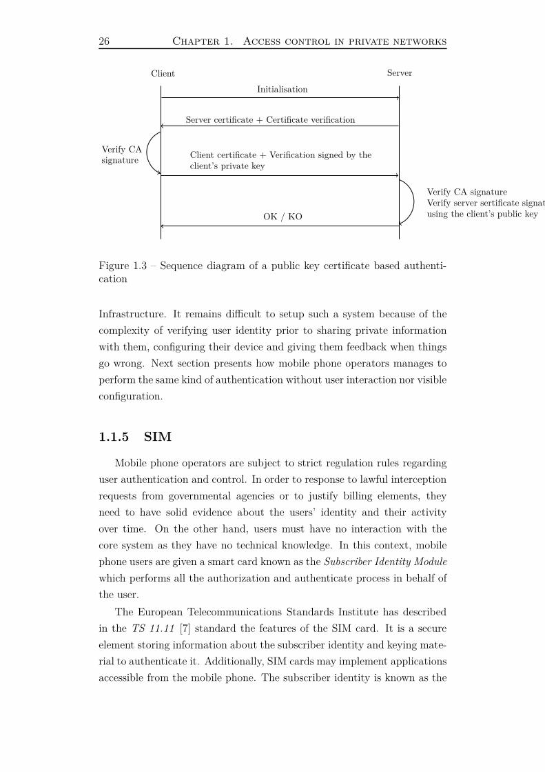
private key associated with its certificate. Figure 1.3 describes a simple
public key certificate authentication. When a client initiates a session, the
server sends its certificate along with a verification request materialized by
a random challenge. The client, after verifying the server’s identity and the
authority who signed its certificate replies with its own digital certificate.
The response also contains the challenge signed by its private key. Finally
the server can verify in turn the client’s authority and the signature.
In order to perform the certificate based authentication, users have to
configure a software on their device. Indeed because this step requires
sending binary data to an authentication server, it can not be done by a
user on a user interface. Rather the transaction is done in software from
the user device to the authentication server. Depending on the software
program, it could be difficult to configure this service and to give proper
feedback to the user when an error occurs. Moreover the system’s security
is based upon the assumption that the private keys remain private. This
requires proper configuration of the user device in order to prevent access
to that keying material by unintended users and gives the user lots of
responsibility on what he does on his computer to not be compromised.
The last two sections presented a secure way of authenticating users
within a private network using asymmetric cryptography and Public Key
26 Chapter 1. Access control in private networks
Client Server
Initialisation
Server certificate + Certificate verification
Verify CAsignature
Client certificate + Verification signed by theclient’s private key
Verify CA signatureVerify server sertificate signatureusing the client’s public keyOK / KO
Figure 1.3 – Sequence diagram of a public key certificate based authenti-cation
Infrastructure. It remains difficult to setup such a system because of the
complexity of verifying user identity prior to sharing private information
with them, configuring their device and giving them feedback when things
go wrong. Next section presents how mobile phone operators manages to
perform the same kind of authentication without user interaction nor visible
configuration.
1.1.5 SIM
Mobile phone operators are subject to strict regulation rules regarding
user authentication and control. In order to response to lawful interception
requests from governmental agencies or to justify billing elements, they
need to have solid evidence about the users’ identity and their activity
over time. On the other hand, users must have no interaction with the
core system as they have no technical knowledge. In this context, mobile
phone users are given a smart card known as the Subscriber Identity Module
which performs all the authorization and authenticate process in behalf of
the user.
The European Telecommunications Standards Institute has described
in the TS 11.11 [7] standard the features of the SIM card. It is a secure
element storing information about the subscriber identity and keying mate-
rial to authenticate it. Additionally, SIM cards may implement applications
accessible from the mobile phone. The subscriber identity is known as the
1.1. Authentication 27
International Mobile Subscriber Identity which is a global unique identi-
fier. It holds information about the mobile phone operator as well as the
subscriber which is useful when users roam outside their home operator’s
network. Operators welcoming the roaming users can then bill the correct
entity for the usage of their infrastructure. Because SIM cards are physi-
cally protected, nobody can access private information directly. Rather it
exposes encryption algorithm functions to the mobile device like a black
box. When the mobile phone wishes to perform a cryptographic task using
the SIM information, it simply calls the right function which gives it the
result. This way, no sensitive information are exposed.
During the SIM customization process done by the mobile phone oper-
ator, a private key Ki is generated along with the IMSI number. They are
both stored inside the card as well as inside the operator’s database. This
way both sides are aware of the private key and share the same information.
When a mobile phone tries to associate with the carrier’s network, it
sends an access request containing the IMSI number gathered from the SIM
card. That information usually requires the user to enter a PIN code. Once
the operator retrieved the Ki associated with the IMSI number, it generates
a one time use random number RAND and signs it with the Ki using the
A3 algorithm. This gives the first Signed Response called SRES_1. The
RAND number is sent to the mobile equipment which asks its SIM card to
sign it. The SIM card signs using its Ki the random number and produces
the second Signed Response called SRES_2. The mobile device sends it
to the carrier network and waits for its response. The operator compares
the SRES_1 and SRES_2 in order to know if the same Ki was used to
sign RAND. If the two responses match, the mobile phone is authorized
to access the operator network and the user’s identity is confirmed.
Then in order to protect the confidentiality of the user’s data, the com-
munication link between its device and the carrier’s network is encrypted.
The encryption key Kc is derived from the RAND again and Ki using the
A8 algorithm.
The security of the system lays in the fact that the Ki remains secret.
However, researchers have found vulnerabilities in the cryptographic algo-
rithms which can lead to the extraction of the Ki [66]. This might allow
an attacker to duplicate a SIM card.
Carrier grade operators are able to provide secure and seamless access to
28 Chapter 1. Access control in private networks
their networks without including the user in the configuration process. This
challenging task is achieved with a complete control of the SIM fabrication
process by the operator. All the infrastructure is built toward an complete
abstraction from the user point of view. In the context of private network
access, authenticating user with their SIM card is hard because one must
be able to know the Ki. In real life, such infrastructure exists but delegates
the authentication to the user’s operator requiring a strong cooperation.
1.1.6 Summary
This section presented how users can be authenticated inside a network.
The goal of authenticating them is to control who connects to the network.
Indeed sensitive data might be accessible within the private LAN and users
have to be recognized and authorized in order to access them.
To prove its identity, a user must provide information about the secret
he holds. The nature of the secret depends on the authentication scheme.
Multiple schemes were presented involving: passwords, challenges, certifi-
cates and SIM cards. Password based authentication is the least secure but
also the most user-friendly. Indeed because this scheme is easy to imple-
ment, a wide range of services are using it, especially on web sites. Here,
both the user and the authentication server is aware of the password.
More robust authentication schemes involving digital certificate or SIM
leverage cryptographic principles to verify the user secret. They are both
based on a private key which is used to sign some keying material. In the
former case, the server verifies the signature using the client’s public key
included inside its digital certificate while in the latter case, the carrier
operator knows the private key stored inside the SIM card because he cus-
tomized it prior to commercialization. Despite the security enhancement
they bring, these two methods are not easy to setup by individuals.
Next section focuses on network protocols which allow to manage au-
thentications inside a network.

1.2. Authentication protocols for access control 29
1.2 Authentication protocols for access con-
trol
In the previous section, multiple authentication methods were presented.
It allowed the understanding of the different mechanisms and keying mate-
rials needed to verify a user’s identity. This sections focuses on presenting
the various network protocols to transport user authentications. Figure
1.4 describes a general view of a private network where users need to au-
thenticate. From left to right, the user device communicates with a border
controller which communicates with an authentication server. Typically,
the border controller is in charge of controlling the user traffic by decid-
ing whether to forward its traffic or not. It uses cross-layer information to
build custom rules per device. This border controller uses the authentica-
tion server to decide if a user is authorized to access the network.
As a result, two kinds of protocols are presented in this section: from
the user device to the border controller and from the border controller to
the authentication servers.
Border controller
Lcaol authentication server
Internet
Remote authentication server
Figure 1.4 – Session border controller in a Local Area Network
1.2.1 Device to access network
This section presents the different communication protocols between the
user device and the access network. The access network is embodied by an
30 Chapter 1. Access control in private networks
access point which needs to validate that a user equipment is allowed to
access the network.
Two protocols are presented here, the first one uses a user friendly web
interface in order to communicate with the end-user whereas the second is
a machine-to-machine protocol providing stronger security.
Web portal
This is the most user friendly protocol. The user interacts with the
border controller using its web browser. The displayed web page is fully
customizable and permits all kinds of contents to be embedded.
Unauthenticated equipments are authorized to use several network ser-
vices in a degraded mode. To display a web page, the equipment has to
at least have IP connectivity and a domain name resolver. The IP con-
figuration is usually provided by an auto-discovery service such the DHCP
protocol. The equipment requests an IP address by sending a packet on
the Ethernet broadcast address ff:ff:ff:ff:ff:ff. The DHCP server
looks for an available IP address in its address pool and replies to the user
equipment. After the user equipment has acknowledged the IP address, the
DHCP server stores its MAC address inside a lease. The lease has a limited
life time after which the IP address becomes free again. Regarding domain
names resolution, every device needs to be able to resolve any domain name
so their web browser performs an HTTP request which is intercepted by
the border controller. It should not fake the DNS response for legitimate
domain names (where a record exists) because the device might store it
inside a cache disrupting network connectivity after authentication. For
domain names where no record is found, a fake DNS response can be made
to force the browser to perform its request.
Various techniques can be implemented to intercept HTTP requests but
they all have a common characteristic: impersonate the requested server
to reply with either a redirection to the captive portal or directly send the
captive portal. An implementation could consist in using the border con-
troller’s firewall to perform a destination Network Address Translation for
the web traffic of unauthenticated user. This way, their traffic is redirected
directly to the captive portal’s web server. User devices think they are
talking to the remote server they asked (e.g. 1.2.3.4) but it’s actually the
captive portal who responds with an HTTP redirection.
Because the session border controller has a layer 2 connectivity with

1.2. Authentication protocols for access control 31
the user device, cross-layer information can be retrieved via the Operating
System API. The Address Resolution Protocol cache contains a MAC-IP
mapping of all the devices on the network. Given the IP address of an
HTTP request, the web server is able to gather a unique identifier of the
device associated with it. This permits the web server to setup the correct
firewalling rules when the user authenticates.
Captive portal is a good communication interface for end-users because
they are used to face them on the Internet. Web pages can embed multi-
media contents from images to geographic maps including videos, links and
texts. These content types can be leveraged to monetize the Internet access
by promoting local venues, proposing value added services or displaying ads
to the end user.
Though it is an appealing solution, the only usable authentication method
is pass phrase based because it’s the only material a human being can re-
member and type on a computer. Section 1.1.2 spotted weaknesses in
that scheme especially regarding the communication channel. By default,
HTTP uses an insecure channel so it must not be used to transmit user
passwords or sensitive data. Hopefully, a secure version of HTTP can be
implemented over a Transport Layer Security [68] tunnel, this is commonly
called HTTPS. The TLS tunnel is encrypts the data transiting in both
directions and authenticates the server from the client side using server
digital certificates (see section 1.1.4).
The authentication process consists in the user entering its user name
and password inside an HTML form which is then sent onto the border con-
troller’s web server. This type of forms are very common on the Internet
and non-technical users are used to fill them up to login on various websites.
Leveraging client side storage with cookies or server cache memory, the
server can remember the user information to automate future authentica-
tions. Captive portals are also a great tool to give comprehensive feedback
to the user: what went wrong during his authentication, wrong password,
exhausted time credit, what network services he is authorized to use or how
long its session will last. Additionally, the feedback can be translated in
multiple languages allowing a wide range of users to use the same captive
portal. This last argument is crucial for public places welcoming visitors
from all around the world.
Moreover, given the information provided inside the HTTP request
header, the web portal can extract valuable data about the user device.
32 Chapter 1. Access control in private networks
Indeed, web browsers usually send an HTTP attribute called the User-
Agent which is filled with a character string describing the user device:
name and version of the Operating System, browser name, hardware ven-
dor, etc. . . With these information in hands, finer grained filtering can be
done depending on the device the user is using. This is often referred as
Bring Your Own Device where users can bring their personal computer at
work. This feature allows to use different protocol filtering depending on
the device the user is using. For example an administrator using its smart
phone should not be able to access all the machines on the local network
as it is not as trustworthy as a controlled computers from the company.
In summary, web captive portal is a great tool to communicate with non-
technical users. It allows anybody to authenticate against a local database
using a secret password. The portal enhance user experience by providing
feedbacks and value added services. But captive portals suffer from weak
authentication. Next section present a protocol aimed at securing network
access which provide secure authentication.
802.1X
The Institute of Electrical and Electronics Engineers (IEEE) who stan-
dardized local area network protocols (IEEE 802) has defined a standard to
control access to them. This standard is named IEEE 802.1X and uses the
Extensible Authentication Protocol to transport keying materials needed to
authenticate clients.
The EAP protocol is an authentication framework which defines mes-
sages to transport keying materials. It is a very generic protocol which
can be used to transport any kind of authentication method. Each method
presented in section 1.1 has its own RFC defining the parameters to be
sent between a user device and the border controller. The RFCs list in-
cludes EAP-TLS for certificate authentication, EAP-SIM or EAP-PAP for
password based authentication.
In the 802.1X standard, the border controllers are in charge of initiating
EAP sessions with devices trying to associate with them. It is important
to emphasize that IEEE 802 protocols are low level protocols. As a result,
EAP messages are directly sent on the physical link encapsulated inside the
corresponding protocol. As an example, 802.1X can be implemented over
Wi-Fi, a device associates with the access-point which requires an authenti-
1.2. Authentication protocols for access control 33
cation. The device and the access-point then transmit EAP messages over
Wi-Fi frames directly until the end of the EAP session is reached. In the
end, an accept or a reject decision is taken by the access-point letting or
refusing access to the device. As EAP messages transport keying materials
to authenticated the user device, they need to be forwarded to an authenti-
cation server who is able to perform the correct authentication process. A
common solution is to encapsulate EAP packets inside the RADIUS pro-
tocol to route the packets through a layer 3 network. RADIUS is detailed
on the next section.
Because 802.1X is implemented directly over the link layer, unautho-
rized devices have no access to the core network. For instance they can not
retrieve an IP address from the DHCP server nor query the domain name
server. This is a clear improvement regarding security compared to the pre-
vious section. Here all the traffic passing through the network comes from
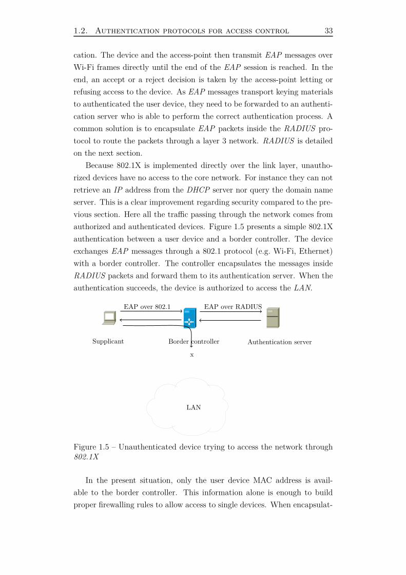
authorized and authenticated devices. Figure 1.5 presents a simple 802.1X
authentication between a user device and a border controller. The device
exchanges EAP messages through a 802.1 protocol (e.g. Wi-Fi, Ethernet)
with a border controller. The controller encapsulates the messages inside
RADIUS packets and forward them to its authentication server. When the
authentication succeeds, the device is authorized to access the LAN.
EAP over 802.1 EAP over RADIUS
Border controller Authentication server
LAN
x
Supplicant
Figure 1.5 – Unauthenticated device trying to access the network through802.1X
In the present situation, only the user device MAC address is avail-
able to the border controller. This information alone is enough to build
proper firewalling rules to allow access to single devices. When encapsulat-
34 Chapter 1. Access control in private networks
ing EAP messages in RADIUS packets, the session border controller adds
a set of information about itself and the device being authenticated. Al-
though no standard exists about what information are mandatory or not,
the MAC address of both equipments, the border controller’s IP address
or the SSID/VLAN assigned to the device are examples of common in-
formation found in such requests. These cross-layer information enables
finer grained filtering on the authentication server to identify the border
controller on which the user is connected, derive its geographic location or
simply log the device’s MAC address of the user.
As stated before, 802.1X is a machine-to-machine protocol in the sense
that it requires two machines to transfer binary data over a network pro-
tocol. On the client side, a software called the supplicant implements the
client’s part. On the other side, the border controller also has a specific
software which implements its part. Configuring supplicants can be hard,
indeed depending on the authentication method, it can require certificates,
private keys and various identities to be configured (tunneled authentica-
tions [36] [12]). Because each software is built differently, there is no stan-
dard method to do that. It is simply not possible for non-technical users
to configure this kind of software as they do not have technical background
on authentication or network access. Moreover, despite proper configura-
tion of the supplicant, feedback can be sloppy in case of errors. Indeed
authentication servers usually return error codes, if any, which are hard to
understand for users.
802.1X is a standard which provides security of user-friendliness. Us-
ing secure authentication schemes, it gives strong security to a local area
network. Compared to captive web portal, the attack surface is drastically
reduced because unauthenticated devices have no access to the network.
Moreover the use of cryptographic algorithm in the authentication process
gives a better level of trust on the users accessing the network. For these
reasons, 802.1X is a perfect solution for enterprise networks where com-
puters are controlled by the company. Indeed users do not configure their
computer hence the lack of user-friendliness is not an issue (given that the
setup works).
After this presentation of protocols to communicate between the user
device and the border controller, next section presents protocols between
the border controller and the authentication server.
1.2. Authentication protocols for access control 35
1.2.2 Authenticator to authentication server
The intent of the section is not to present an exhaustive list of proto-
cols between an authenticator and an authentication server, but rather to
outline the important ones. This section starts with RADIUS which has
been extensively used in access networks for the past twenty years.
RADIUS
The Remote Authentication Dial In User Service protocol (RADIUS) is
a network protocol developed by Livingston Enterprises, Inc. in 1991 later
standardized by the IETF. It is described in RCF 2865 [19]. This protocol
is intended to manage network access from a centralized point. Access is
managed using Authorization, Authentication and Accounting transactions.
It uses UDP as transport protocol to communicate between different enti-
ties.
The protocol defines a list of packet types to be used to request access,
exchange challenges or grant/deny access. Each packet contains a list of
attribute value pairs. RFC defines a lot of attributes including user name,
user password, allows vendor specific attributes to be defined using custom
dictionaries.
When the border controller needs to perform an access request, either
coming from its web server or from an 801.1X session, it sends a RADIUS
Access-Request to the authentication server containing the user identity and
other parameters about itself. If there is enough information in the Access-
Request to authenticate the user (e.g. a plain text password based authen-
tication), the server replies with a yes/no packet respectively Access-Accept
and Access-Reject. When the authentication method requires more than
one step, for instance password challenge seen in section 1.1.2 or client cer-
tificate from section 1.1.4, the authentication server replies with an Access-
Challenge. The border controller is then forced to respond correctly to the
challenges until the authentication server finally sends an Access-Accept or
Access-Reject packet.
When a user is authorized to access the network, the border controller
can optionally send an accounting start request to provide the server with
information about the user session. Typically, this request holds the ac-
counting session identifier that will be sent again at the end of the session.
The border controller is then supposed to count the amount of time, packets
36 Chapter 1. Access control in private networks
and data consumed during the session so they can be sent when the user
disconnects. When this happens, an accounting stop request telling the
server the user session has ended is sent. This request contains account-
ing data as well as the reason why the session has terminated. During
users’ session, the border controller can send interim requests to inform the
server about the accounting information on the runtime. These packets are
sent periodically every few minutes. Care must be taken not to overwhelm
the RADIUS server with too many requests. Leveraging the RADIUS in-
terim, a server can detect terminated sessions even if the accounting stop
packet has been lost. Indeed whenever a session is no longer updated by
interim requests, one can assume something went wrong and that the ses-
sions can be closed. Moreover, user session information can be updated by
the server following an interim request using the Change of Authorization
(CoA) packet. This mechanism takes advantage of a NAT property where
a packet emitted in response to a request will correctly be delivered to the
sender. If a packet is sent by a server to a client’s public IP without prior
request, the router gateway would have no rule to forward it to the right
destination. Hence in response to an interim request, the RADIUS server
can reply with a CoA response containing new attributes to apply to the
user session: bandwidth, session maximum duration, class of filtering or
even ordering a disconnection.
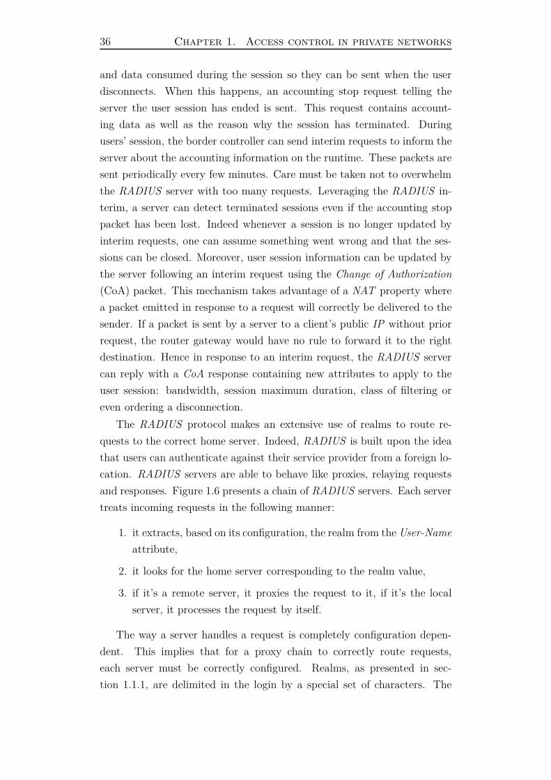
The RADIUS protocol makes an extensive use of realms to route re-
quests to the correct home server. Indeed, RADIUS is built upon the idea
that users can authenticate against their service provider from a foreign lo-
cation. RADIUS servers are able to behave like proxies, relaying requests
and responses. Figure 1.6 presents a chain of RADIUS servers. Each server
treats incoming requests in the following manner:
1. it extracts, based on its configuration, the realm from the User-Name
attribute,
2. it looks for the home server corresponding to the realm value,
3. if it’s a remote server, it proxies the request to it, if it’s the local
server, it processes the request by itself.
The way a server handles a request is completely configuration depen-
dent. This implies that for a proxy chain to correctly route requests,
each server must be correctly configured. Realms, as presented in sec-
tion 1.1.1, are delimited in the login by a special set of characters. The

1.2. Authentication protocols for access control 37
RADIUS Clients
RADIUS proxy
serviceprovider.com
MYDOMAIN
RADIUS proxy
RADIUS proxy
RADIUS server
RADIUS server
Figure 1.6 – Chaining of RADIUS proxies which route requests to the rightservice provider
first example was the email address where the realm was located after
the ’@’ character but other formats, for instance the Windows domain,
place the realm in prefix. As a result, realm formats has to be config-
ured inside the RADIUS server. Describing a format essentially consists
of telling whether the realm is a prefix or a suffix and what is the de-
limiter. The order in which realms are extracted is also really impor-
tant. Let’s take a user name which potentially contains two realms: MY-
DOMAIN\\[email protected]. Depending on the order,
the server might extract respectively the realm MYDOMAIN or servi-
ceprovider.com and the user name [email protected] or
MYDOMAIN\\john.doe. As the realm tells the server where to send the
request, it is important that the matching is done in the right order. After
finding the correct home server to proxy the request to, the current server
has the possibility to modify the User-Name attribute to remove the realm
section, the user name is now stripped. The stripping hides the local realm
to the remote server, for instance in the previous example, MYDOMAIN
corresponds to a local Windows domain on which the user is connected, it
should not be treated as part of the user name by the home server hence it
38 Chapter 1. Access control in private networks
has to be stripped prior to proxying the request. Though convenient, not
all servers need to strip the user name, some might only route the request
to another server without matching a local realm.
RADIUS has been designed during a time when data confidentiality and
security was not a trending topic on the network community. It explains
why it lacks common encryption features present in most authentication
protocols nowadays. In practice, the only security feature present in RA-
DIUS is the use of a shared secret between two servers. This secret is
used to hash the user password so it is not sent in plain text. Besides
the fact that it prevents password eavesdropping, it also ensures that the
two servers know each other. On the one hand, this prevents unauthorized
access to a server (hence to a user database) but on the other hand, this
is an obstacle to cooperation between actors. Indeed, for a network access
provider who wants to cooperate with different service providers, both him
and the service provider need to accordingly configure their servers and test
everything works as expected.
Moreover, the use of UDP gives no insurance about the arrival of packets
to the other end which is one of the biggest RADIUS weakness. Servers can
not reliably behave to packet loss which is problematic for AAA protocol.
The reason why TCP was not chosen is because it was meant to be used
between networks with high latency. Back in the days, TCP performed
very poorly in such circumstances hence UDP has been chosen.
Coming back to security, RADIUS uses MD5 to hash the user password
concatenated with the shared secret. This algorithm suffers from several
weaknesses which makes it insecure to use today [72] [32]. Such hashes are
rather easy to break mainly because of the collision rate of MD5 . Further-
more, this only protects the password, not the rest of the data. This is a
major issue as sensitive data about the user or the network are exchanged
in RADIUS packets. Thus, it is good practice to encrypt RADIUS traffic
when it’s sent on an untrusted network (e.g. the Internet). The industry
has adopted ipsec as a good solution to implement this encryption layer.
It provides IP payload encryption and integrity check with the benefit of
being transparent for upper layer protocols.
To cope with RADIUS weaknesses, its successor, DIAMETER has been
designed. It uses TCP or SCTP as transport layer and advises to use
TLS encryption at the socket layer. It can be backward compatible with
RADIUS but is aimed to perform better than its ancestor. Though it has
1.2. Authentication protocols for access control 39
appealing features built in, this newer protocol is still not widely deployed,
only carrier grade operators have made a use of it by now.
Next section presents a protocol which is not stricto sensus a network
protocol but can be leveraged to implement a user database in addition to
user authentication.
Lightweight Directory Access Protocol
LDAP is an applicative protocol to access and manage information di-
rectory services over the network. It is specified by the IETF as multiple
RFCs. The latest one defines the Version 3 in the RFC 4511 [44]. LDAP
uses either TCP or UDP as transport layer on port 389 with no encryption,
or port 636 with TLS encryption.
Information directories store data according to their directory schema.
This schema defines the data structure with a number of elements per
object:
— Attribute syntax - defines what information can be stored in an
attribute
— Matching rules - defines how to compare the attribute values
— Object classes - defines a set of required and optional attributes
identified by a unique name
Data is stored in the entry’s attributes. Each entry has at least an
Object class which tells what kind of object it represents and how clients
may interact with them. Clients can access the server schema to learn
about the elements’ structure as well as the hierarchy of entries. Entries
are identified by a distinguished name called dn, it is neither an attribute
nor part of the entry. The dn contains a common name (e.g. John Doe)
plus the dn of its parent entry.
For example, a user can be represented by the person object class. Its
common name is “John Doe”and it is part of the example.com provider.
Hence its dn can be represented as:
dn: cn=John Doe,dc=example,dc=com
The person class requires no attribute itself but inherits from the top
object class, a special abstract class, forcing the definition of the object class
attribute. The person object class defines optional attributes including the
userPassword, telephoneNumber or description.
Clients access the directory server using a set of operations: add, search,
delete, modify, bind . . . When a session starts, the bind operation allows the
40 Chapter 1. Access control in private networks
user to authenticate against the directory. The simple bind uses the user’s
dn as well as its password in plain text to check if the userPassword entry
matches. Such operation should be encrypted to avoid eavesdropping. A
wider range of authentication mechanisms is provided by the Simple Au-
thentication and Security Layer bind such as Kerberos [41] authentication
or TLS authentication using certificates. Once the client is bound to the
directory, he has access to a subtree corresponding to his identity. Further-
more, he gains the rights to use (or not) other operations.
Leveraging the bind mechanism in addition to the information structure
makes LDAP a great tool to manage users in a guest access environment.
After users being authenticated against the directory, they have only ac-
cess to their information. Furthermore, the network topology including
incoming networks, zone definition, network services can be stored in that
directory allowing the retrieval of key information for each user.
1.2.3 Summary
The combination of protocols presented on the last section allows to
implement all kinds of network access controls. Indeed based on one’s
needs, user-friendly setup with value added services can be implemented
using a captive web portal or on the other side, tight access control can
be implemented using 802.1X and RADIUS. Leveraging the capacity of
every protocols and combining them together permit to implement custom
filtering and build appropriate architecture to answer any kinds of needs.
The authentication process aims at binding an identity to a network
equipment in order to grant it network access. This process is possible here
because all the equipments belong to the same private network. As a result,
border controllers are able to identify uniquely user devices using OS API.
It is important to acknowledge that these API are platform dependent and
vary from one OS to another. In chapter 2 and chapter 3, this lemma is
broken which complicates the architecture.
In the present state of the presentation, one can store user identities in
databases, control user identity via multiple authentication methods and
monitor user sessions over time. The missing piece to have a complete net-
work access control solution is flow control. Next section presents multiple
techniques to identify and filter user activity on the network and how they
infer or not with user privacy.
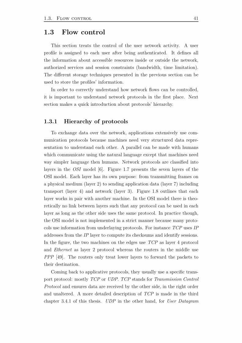
1.3. Flow control 41
1.3 Flow control
This section treats the control of the user network activity. A user
profile is assigned to each user after being authenticated. It defines all
the information about accessible resources inside or outside the network,
authorized services and session constraints (bandwidth, time limitation).
The different storage techniques presented in the previous section can be
used to store the profiles’ information.
In order to correctly understand how network flows can be controlled,
it is important to understand network protocols in the first place. Next
section makes a quick introduction about protocols’ hierarchy.
1.3.1 Hierarchy of protocols
To exchange data over the network, applications extensively use com-
munication protocols because machines need very structured data repre-
sentation to understand each other. A parallel can be made with humans
which communicate using the natural language except that machines need
way simpler language then humans. Network protocols are classified into
layers in the OSI model [6]. Figure 1.7 presents the seven layers of the
OSI model. Each layer has its own purpose: from transmitting frames on
a physical medium (layer 2) to sending application data (layer 7) including
transport (layer 4) and network (layer 3). Figure 1.8 outlines that each
layer works in pair with another machine. In the OSI model there is theo-
retically no link between layers such that any protocol can be used in each
layer as long as the other side uses the same protocol. In practice though,
the OSI model is not implemented in a strict manner because many proto-
cols use information from underlaying protocols. For instance TCP uses IP
addresses from the IP layer to compute its checksums and identify sessions.
In the figure, the two machines on the edges use TCP as layer 4 protocol
and Ethernet as layer 2 protocol whereas the routers in the middle use
PPP [49]. The routers only treat lower layers to forward the packets to
their destination.
Coming back to applicative protocols, they usually use a specific trans-
port protocol: mostly TCP or UDP. TCP stands for Transmission Control
Protocol and ensures data are received by the other side, in the right order
and unaltered. A more detailed description of TCP is made in the third
chapter 3.4.1 of this thesis. UDP in the other hand, for User Datagram
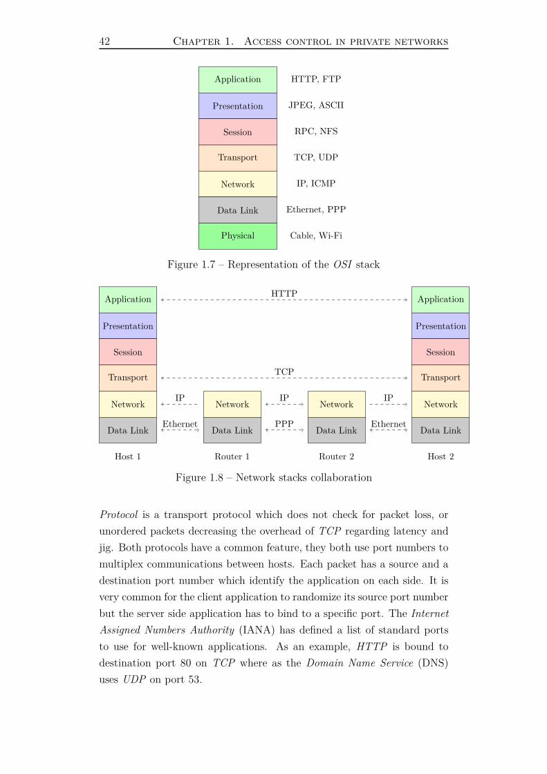
42 Chapter 1. Access control in private networks
Application HTTP, FTP
Presentation JPEG, ASCII
Session RPC, NFS
Transport TCP, UDP
Network IP, ICMP
Data Link Ethernet, PPP
Physical Cable, Wi-Fi
Figure 1.7 – Representation of the OSI stack
Application
Presentation
Session
Transport
Network
Data Link
Application
Presentation
Session
Transport
Network
Data Link
Network
Data Link
Network
Data Link
Host 1 Router 1 Router 2 Host 2
HTTP
TCP
IP IP
Ethernet PPP
IP
Ethernet
Figure 1.8 – Network stacks collaboration
Protocol is a transport protocol which does not check for packet loss, or
unordered packets decreasing the overhead of TCP regarding latency and
jig. Both protocols have a common feature, they both use port numbers to
multiplex communications between hosts. Each packet has a source and a
destination port number which identify the application on each side. It is
very common for the client application to randomize its source port number
but the server side application has to bind to a specific port. The Internet
Assigned Numbers Authority (IANA) has defined a list of standard ports
to use for well-known applications. As an example, HTTP is bound to
destination port 80 on TCP where as the Domain Name Service (DNS)
uses UDP on port 53.
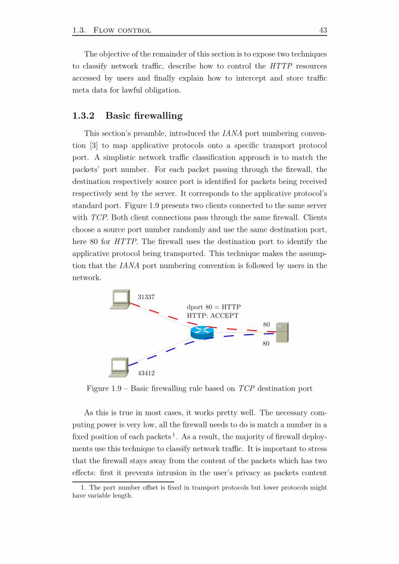
1.3. Flow control 43
The objective of the remainder of this section is to expose two techniques
to classify network traffic, describe how to control the HTTP resources
accessed by users and finally explain how to intercept and store traffic
meta data for lawful obligation.
1.3.2 Basic firewalling
This section’s preamble, introduced the IANA port numbering conven-
tion [3] to map applicative protocols onto a specific transport protocol
port. A simplistic network traffic classification approach is to match the
packets’ port number. For each packet passing through the firewall, the
destination respectively source port is identified for packets being received
respectively sent by the server. It corresponds to the applicative protocol’s
standard port. Figure 1.9 presents two clients connected to the same server
with TCP. Both client connections pass through the same firewall. Clients
choose a source port number randomly and use the same destination port,
here 80 for HTTP. The firewall uses the destination port to identify the
applicative protocol being transported. This technique makes the assump-
tion that the IANA port numbering convention is followed by users in the
network.
31337
80
43412
80
dport 80 = HTTP
HTTP: ACCEPT
Figure 1.9 – Basic firewalling rule based on TCP destination port
As this is true in most cases, it works pretty well. The necessary com-
puting power is very low, all the firewall needs to do is match a number in a
fixed position of each packets 1. As a result, the majority of firewall deploy-
ments use this technique to classify network traffic. It is important to stress
that the firewall stays away from the content of the packets which has two
effects: first it prevents intrusion in the user’s privacy as packets content
1. The port number offset is fixed in transport protocols but lower protocols mighthave variable length.
44 Chapter 1. Access control in private networks
can hold sensitive data ; but on the other hand, it lacks the ability to gather
valuable data about the traffic content (e.g. application headers). The limit
between a packet’s header and its content can be tricky though. Strictly
speaking, each network protocol has a header followed by a payload, its
content. Hence depending on the layer, the content changes. For example
at the IP layer, the header contains IP addresses but for the Ethernet pro-
tocol, they are part of the payload ! In this thesis, the header is composed
by all the network protocols headers: link, network and transport. The
rest is treated as applicative data.
Getting back to flow filtering, the main problem of only looking at port
numbers is that clients and servers can use applicative protocols on non-
standard ports as long as they agree with each other. This can lead to
filtering evasion by users in the network because they can use a restricted
protocol on the port instead of an authorized one. For instance, in most
guest networks the HTTP protocol is guaranteed to be available but VPN
protocols might not. An ill-disposed user could set up his VPN server
to use the port 80 and connect to it from the guest network without any
problem because the firewall will treat the VPN traffic as if it was HTTP
traffic. In addition, VPN s and tunneling protocols permit to transport
data, even lower layer protocols, inside them leading to a complete bypass
of the firewalling rules in the event where the user routes all his traffic
inside.
To prevent such filtering bypass, more advanced techniques can be de-
ployed, the next section presents one of them.
1.3.3 Deep packet inspection
To address the previous section’s limits about network service classifica-
tion, more efficient solutions have arisen. They are known as Deep Packet
Inspection techniques (DPI). The general idea is to look into the packets’
content rather than just their headers. It’s a very challenging task for mul-
tiple reasons. First the data in the packets’ payload might be anything,
from a standard protocol such as HTTP or DNS to unorganized plain text
data including encrypted traffic. Although useful data is usually located
in the protocols header like in lower layer protocols, applicative protocols
headers are not replicated in every packets. Furthermore, there is no guar-
anty on the header location inside a packets flow, for instance underlaying
protocols might require to initiate a connection prior to sending applica-
1.3. Flow control 45
tive data. As a result, extracting all the necessary data to identify the
applicative protocol requires a number of packets to be collected.
In addition to this complexity, the protocol classification, even with
enough data in hands, is hard. Indeed there is a great protocol diversity
and a huge number of them which requires a fair amount of computation
to parse and identify what protocol is being used. Because this has to be
done for every transactions between a client and a server, the computing
power needs to increase with the traffic growth. As a result, DPI solutions
are mostly deployed in data centers where computing power is sufficient.
In the context of network access control, DPI solutions are very power-
ful tools because they permit to filter user traffic on a service based. This
prevents for instance the filtering evasions presented before where a tun-
neling protocol where used on a non-standard port number. Furthermore,
when traffic is encrypted and a server-side authentication is performed by
the client (e.g. HTTPS), it is feasible to extract the server’s name from
its certificate. This can be leveraged to identify the website being accessed
by the client despite the fact that all the traffic is encrypted. It is then
possible to know that a user accessed popular websites such as Facebook,
Youtube or Google and even forbid him the access.
It is pretty clear from the description given in this section that DPI
solutions are intrusive in regards to the traffic content. For real users it
implies violating their privacy by looking at the resources they access and
the content of their communications. For machines, DPI can be used to
eavesdrop on sensitive data being exchanged between different locations.
All these issues raise great concerns on the Internet because DPI can be
used both the for the good and the evil with little control over what is
being done.
1.3.4 URLs filtering
In various situations, users might be disallowed to access some websites:
pornography for children, games and videos for employees of a company or
phishing websites for any kind of users. To prevent users from accessing
such websites, a middle box needs to intercept the web traffic and decides
whether he is allowed to access it.
To intercept the web traffic, the middle box implements what is com-
monly called a transparent web proxy. As its name states, user web browser
will not detect that the connections it makes with web servers are being

46 Chapter 1. Access control in private networks
intercepted and, maybe, modified by the proxy. It is important to note that
this does not concern encrypted traffic such as HTTPS connection where
transparent proxies would break the chain of trust between the client and
the server. 1.10 demonstrates how HTTP packets are intercepted by the
middle box and relayed to the web server. The idea behind this is to in-
tercept the TCP session so that the client talks directly to the middle box
thinking it’s the server he asked for. Then when the proxy receives the
HTTP request from the client’s browser, it establishes a TCP connection
with the real web server and sends the request to it. The returning path is
trivial as it is a copy of the sending but in reverse.
With the HTTP request in hand, the requested URL is easily extracted.
The proxy can then look up in its database to decide, given the user profile
derived from the user IP address, if it should deny access to the resource.
This can be implemented using open source solutions such as squid plus
squidguard [4] [5] with an external helper program to derive the user profile
from a given IP address.
Device Web Proxy Web Server
TCP initialisation(dest is the Web Server)
Reply with a spoofed
IP address
HTTP requestTCP initialisation
TCP reply
HTTP request
HTTP reply
HTTP reply
Figure 1.10 – Web proxy interception
URL filtering is a powerful tool to control user activity on the web.
Despite preventing unwilling access to websites, it permits to restrict cat-
egories of websites which are prohibited in certain places and countries.
Speaking of which, next section discusses about lawful obligation in gen-
eral.
1.3. Flow control 47
1.3.5 Lawful obligation
In many countries, Internet access owners are liable for its usage. The
European Parliament has voted a directive in 2006 which forces telecom-
munication actors to store user logs from six months to two years. Though
this directive was canceled in 2014, many European countries already trans-
posed it in their own right. It is unsure for the moment if these countries
will go back or not on that subject.
Since the law requires data retention in order to identify a posteriori user
activities within any networks, middle boxes have to record user activity
on the runtime. The law is evasive regarding the necessary data to record.
Basically it has to be possible to identify the source of a communication,
its destination, the date and duration, its type and the machine used to
communicate. From a technical point of view one can interpret this as
storing the user’s equipment IP and/or MAC addresses along with the user
identity, the server being accessed as well as the transport port number
(i.e. service).
The storage of all collected data requires a fair amount of disk space
as well as computing power. Indeed in sites with a high user activity,
gigabytes of data are generated every months. Furthermore, they have to
be replicated in case of a disk failure. Taking into account the retention
duration, it is a likely event. Adding extra equipments to store the user
logs is an extra cost only affordable by owners who absolutely require it.
Most small venues owners do not have the money to buy these kinds of
hardware.
Another aspect of this lawful obligation is that it is fairly intrusive in
regard to user privacy. Indeed, user data are being stored by the Wi-Fi
provider in a rather obscure way since nobody controls how data are being
stored. Most of the time, the network administrator has access to all data
including visited URLs, which might contain compromising and sensitive
data. Of course users have to be aware that their data are being recording
and providers are required to inform their public about the type of data
the store and they duration of the storage.
Finally, the benefits of these obligations are somehow questionable. The
objective is to identify a user on the Internet in the event of a law violation.
But as described in section 1.1.1, an identifier might not be sufficient to
match a user identity, plus the user identity is not always known by the
provider. Hence, he will record user data without the ability to identify the
48 Chapter 1. Access control in private networks
users, making this plan of action useless.
1.4 Summary
This fist chapter has been the occasion to present access control in
private networks. It outlined the importance of user authentication to
perform custom network filtering. User identity is verified by an authen-
tication server which ensures the user possesses the right secret. Multiple
authentication methods were presented providing different level of security.
The more secure they are, the lest user-friendly they get. This trade-off is
common in security. To transport the authentication materials, multiple
protocols were presented. Some of them, RADIUS for example, permit to
route authentication requests through a multitude of servers. The rout-
ing extensively uses realm names inside the request to choose whether to
forward it to another server or to perform the authentication locally.
Then when the authentication succeed, the user identity is mapped with
its device. This allows to build firewalling rules to authorize and filter the
user traffic. A couple of techniques were presented to control user traffic:
the first one only inspects up to the transport layer of packets’ headers to
classify the traffic and take a decision whether to accept or deny it. The
second one takes a deeper look inside the packets’ content to match the
applicative protocol being carried. Additionally, meta-data can be stored
by the network gateway in order to reply to lawful authority’s requests.
These meta-data are valuable because they allow to identify the origin of
a network activity on the Internet.
Given the knowledge acquired during this network access control state
of the art, it is clear that each piece uses a specific network layer. Packet
inspection and firewalling use low layer information, message routing and
secure channel mid layer and identity management plus authentication the
application layer. This demonstrates the need of a cross-layer approach to
build a network access control solution. Indeed, every pieces need informa-
tion from others: firewalling is dependent on the user’s identity, authenti-
cation depends on the user location (based on its network device address)
and authentication messages transport network information.
In the present situation, each actor is able to retrieve cross-layer in-
formation either from the messaging protocol (e.g. RADIUS) or directly
from its Operating System’s API. As a result, some equipments have to
1.4. Summary 49
be hosted within the same local network. Obviously the session border
controller is one of them because it is in charge of filtering user traffic but
the captive portal is another one. Indeed it has no other option to gather
cross-layer data but from the local Operating System’s database. Hav-
ing an access control management instance per network is expensive and
hard to maintain. Mutualizing this entity between multiple networks is
a clear improvement. Next chapter presents a mutualized network access
controller, hosted in the Cloud. It outlines the technical challenges brought
by this new architecture in terms of cross-layer information sharing.


Chapter 2
A mutualized approach
This second chapter presents the evolution of network access control
with the rise of Cloud computing. Given the benefits of hosting virtual ma-
chines inside a data center in terms of storage capacity, computing power,
bandwidth, replication and high availability, it is appealing to consider
having a network controller there. Moreover, some Wi-Fi access points are
now able to interact with a remote captive portal allowing to decouple the
controller from the border access gateway. Great benefits can be drawn
from such architecture because it removes the need of having a network
controller per-site by mutualizing it in the Cloud.
Although it brings many benefits, this architecture brings another set of
challenges. This architecture has to overcome the fundamental cross-layer
problems, but it also has to realise this in a distributed environment. Given
the potential of this architecture from an industrial point of view, it was ap-
pealing for the company to have a concrete implementation of this proposal
rapidly. As a result, this chapter presents both the challenges brought by
the distributed environment in regards with the cross-layer problems and
the practical implementation done to overcome these challenges inside the
Ucopia product. It is important to note that this implementation is an
inherent part of the Ph.D because it allowed to face various problems when
hosting the access network controller remotely.
The chapter is structured around four sections: it starts with a brief
presentation of the motivations in section 2.1, both pecuniary and the po-
tential to scale. Then the architecture is detailed in section 2.2 with a focus
on the technical challenges. The third section 2.3 deals with the implemen-
tation of the controller and how technical challenges have been overcome.
Finally the last section 2.4 discuss the limitations of this solution and how
52 Chapter 2. A mutualized approach
they can be addressed.
2.1 Motivations
The network access control market is strongly segmented. This results
in a situation where there is on the one hand clients needing to control
tens of thousands of simultaneous users and willing to afford it. And on
the other hand clients who only need to sporadically control the access on
their Wi-Fi hotspot and are not willing to pay for an expensive solution.
In between there is clients wanting to equip a large number of distant sites
and have a unique control interface to manage all their hotspots. While
monolithic controllers, such as the Ucopia solution presented in the first
chapter 1.4, are perfect to control a large amount of users on the same
location, they are too expensive for very small venues and can not scale
with sites multiplication. Indeed as the controller holds the role of border
gateway, one needs to setup a controller per site which rapidly becomes
way too expensive to configure and constantly operate.
To address this market segment, it is crucial either to drastically reduce
the controller’s cost which seems difficult simply because of hardware costs,
or to mutualize the controller among multiple clients. The latter proposi-
tion is interesting in the current context. Despite virtualization progress,
having multiple virtual machines in data centers is still quite expensive
but because clients share the same hardware, the more they are, the less
it costs. Plus data centers provide platform flexibility permitting to adapt
the hardware needs, in terms of bandwidth and computing power, on de-
mand. The problem with concrete hardware is that it needs to have enough
capacity to hold its maximum charge though it might be idled the rest of
the time (e.g. . Amazon’s black Friday).
Having a mutualized controller hosted in a data center modifies the cost
distribution between Opex and Capex, indeed it is no longer required to
buy the hardware resulting in almost no Capex but it increases the Opex
because the hardware is rented. While in the short term virtual machine
hosting is cheaper than concrete hardware, the expenses balance overtime
hence to make a Cloud application profitable, it’s a good idea to share
it between multiple clients. This splits the Opex among all the clients
reducing the cost of the solution.
Additionally the on-site environment may not be appropriate to host
2.2. Proposed architecture 53
computer equipments. Heat, humidity and power outage. . . are potential
causes of damage to the on-site controller. Data centers are specifically de-
signed to be a safe environment to run computers. Similarly, real hardware
suffer from failures, disks, memory, or network cards may break leaving the
whole system inoperable. To provide high availability, one needs to have
spare controllers on-site in order to take over in case of failure, which mul-
tiply the solution’s cost. Data centers natively address this by providing
hot virtual machine migration and hardware redundancy.
Despite all the advantages of data center hosting for the network con-
troller, an on-premise border controller is still required to physically control
user traffic. Nowadays, Wi-Fi access-points are able to play this role. As
they were already vital in previous architectures, it is very convenient to
reuse them here with additional features. Moreover, this kind of lightweight
equipments is more resilient, mainly because they do not have any device
that moves (e.g. hard drives), hence better suited to be hosted on the
premise environment. The proposed architecture intends to integrate a
wide range of Wi-Fi vendors hardware already available on the market.
The remote controller has to be implemented to correctly interact with
each vendor’s hardware.
Last but not least, the proposed architecture does not rely on network
tunnels to forward user traffic to a central controller. It prevents adding
packet delays, single points of failure and reducing bandwidth [14]. Au-
thenticated user traffic is directly routed onto the Internet using the local
ADSL or optic fiber access. The overall architecture capacity grows with
the number of sites and adds very little overhead (only a captive portal).
Moreover, the remote controller benefits from the platform flexibility to in-
crease its capacity on-demand. It is a clear improvement of existing setups
which either had to have one controller per-site or to build network tunnels
through the Internet reducing the end-users’ quality of service.
Next section presents the detailed architecture proposal which outlines
the roles of the local and remote equipments as well as the technical issues
that need to be addressed in order to be implemented.
2.2 Proposed architecture
The proposal detailed in this section tries to control user connected to
different sites, distant with each other and possibly owned by different cus-

54 Chapter 2. A mutualized approach
tomers, from a mutualized controller hosted in a data center. These two
entities interact together through the user browser to exchange authenti-
cation materials in order for the border controller to trigger a RADIUS
access request on the remote controller. Figure 2.1 presents the big picture
of these interactions, first the user device requests a web page, it is redi-
rected onto the central captive portal where the user enters its credentials.
The captive portal crafts a request sent by the user web browser to the
border controller which triggers the RADIUS authentication. Depending
on the response, the border controller opens some network access to the
user device.
User Access Point Central Portal RADIUS Internet
IP negociation
GET / HTTP/1.1
Host: www.google.com
Redirectionhttps://portal.com/. . .
GET https://portal.com/. . .
Display portal
POST credentials
Redirect
POST credentials
Access-RequestAuthorize
andAuthenticate
Access-AcceptRedirectwww.google.com
Acct-Start
Web traffic
Figure 2.1 – Sequence diagram of a user device authentication
When the session ends, the border controller sends a RADIUS account-
ing stop to the central controller in order to notify and update the user
session in central.
In this architecture, the user’s web browser is used as a communica-
tion medium between the border controller and the central portal. This
medium permits the transfer of valuable cross-layer information between
2.2. Proposed architecture 55
them: network information about the user device and the border controller,
user credentials and feedbacks. But because data are transfered via the user
device, they may be altered by him. As a result, it can not be used for
critical operations such as user authentication. Here the RADIUS protocol
provides a more secure communication channel which can not be tampered
by the user.
Next section details the roles of the local equipment in this architecture.
2.2.1 Local equipment
The local border controller is in charge of controlling user access and
filtering their traffic. It uses the remote controller as authentication server
to decide whether a user device is authorized to access the local network
or not.
The local equipment redirects web requests issued by unauthenticated
users to the central web portal. This redirection is done by answering with
the HTTP 301 or 302 code. Both codes mean that the requested page
has moved, respectively permanently or temporarily. The URL on which
the user is redirected holds a number of information including network
information such as the user device’s IP and MAC addresses, the SSID on
which it is associated and informations about the URL it tried to reach.
These pieces of information are highly valuable for the captive portal as
it needs them to perform authorization checks prior to letting the user
authenticate. Because the remote controller is located outside the private
network, the user device’s network information are hidden by the Network
Address Translation (NAT) mechanism of the Internet gateway. Indeed
private networks has been implemented behind NATs in order to reduce the
IPv4 address exhaustion [48] by using a unique public IP address for the
entire network. A gateway is responsible of translating private IP addresses
into a routable public address and vice versa. So from the public Internet,
all traffic coming from a private network is seen as being emitted by the
same address. This prevents the captive portal from identifying devices on
the same network. For example how can it tell whether two requests were
emitted by the same device or not.
The information sent in the URL are crucial to implement a consistent
captive portal in the Cloud. Among them, IP and MAC addresses are
absolutely necessary to differentiate devices whereas the other ones might
be optional.

56 Chapter 2. A mutualized approach
Whenever the central captive portal decides to trigger the user authen-
tication, it orders its device to perform an HTTP request targeting the
border controller. To handle this request, the border controller hosts a
web server in order retrieve the user name and password and to execute
an external script which performs the RADIUS request. The information
transmitted include the ones presented in section 1.2.2 as well as others
related with the border controller’s identity. They can be used to identify
the location of the user or to track its mobility over the network.
The RADIUS Access-Accept response holds valuable data regarding the
user session. User profile, maximum session duration, quality of service are
parameters which affect how the user traffic is handled. Though it is not
possible to represent network services with RADIUS which prevents from
sending the set of allowed services for the user session, one can implement
this feature by sending a user profile that matches a filtering class configured
on the local border controller. For instance one could setup a guest profile
on the central database which matches a guest filtering class on the local
border controller. The profile name is usually sent in the Filter-Id RADIUS
attribute. Following the reception of the Access-Accept, the local equipment
should send a RADIUS Accounting-Start packet in order to tell how to
identify the user session to the central controller.
Then when the user session ends, the border controller is in charge of
sending an Accounting-Stop packet containing all the session data. They
include the amount of packets sent and received, the amount of data they
represent, the session duration and the session ending reason. Furthermore,
the user device is now considered unauthenticated again.
2.2.2 Remote controller
To control user access on the different site locations, border controllers
need one or more remote controllers to provide a captive portal and an
authentication server. For configuration ease and consistency, the remote
controller is a place of choice to host the captive portal. It provides a
unique configuration shared among all sites with potentially customized
visuals depending on the user’s location. The user central users database is
leveraged to enable roaming between different sites while storing the session
information in a unique place. Moreover, the remote controller aggregates
the data from every local equipments including configuration, session logs,
billing information and so on. . .
2.2. Proposed architecture 57
Regarding technical requirements, the web portal has to understand the
parameters received from the redirection URL. Though they differ from
one vendor to another, they are key to implement a decent authorization
algorithm. Beside the device network information which is mandatory, a
helpful information is the location on which the user is connecting from.
This might be given by the SSID label of the Wi-Fi network, a zone label
which is configured on the border controller and included in the redirection
URL or even with a virtual network label supported by some vendors.
The idea with this is to display a different web portal depending on the
user’s location. For instance one could have a web portal for the SSID
“Book Store”which is broadcasted by a multitude of border controllers and
another one for the rest of the SSIDs except on a particular virtual network.
Once the user has decided to access the network, usually by entering
its credentials, the web portal has to make its browser craft an HTTP
request targeting the border controller. This is the request which triggers
the RADIUS Access-Request packet, hence it needs to include the user
credentials as well as all the necessary information required to perform the
RADIUS authentication. The way of building this request is detailed in
section 2.3.1.
Finally, the remote controller hosts a RADIUS server to handle user
authentications. This server is in charge of authorizing and authenticat-
ing users willing to access the network. It might implement multiple au-
thentication schemes including plain text password 1.1.2 or password chal-
lenge 1.1.2. Moreover it has to handle session start and stop packets in
order to store the information sent by the border controllers in a unique
database. Accounting-Stop packets are really important when billing users
based on their session time. It is critical to ensure that they are either
correctly received by the server or that the server has a way of detecting a
session which has ended with no stop packet received. In order to ensure
the Accounting-Stop packet is received by the server, the border controller
has to verify the server’s RADIUS acknowledgment. But this is not enough
in the event where the border controller is rebooted for instance. In this
case, it might lose all the current sessions information so no way of sending
the appropriate stop packets. To address this issue, border controllers can
send accounting interim packets regularly so the server can detect when-
ever it no longer receives interims for a particular user session. Accounting
interim must be used with care though as it increases the amount of pack-
58 Chapter 2. A mutualized approach
ets exchanged between border controllers and the server and might cause
major downsides regarding performance.
To provide the same user experience as the former architecture, a few
technical challenges have to be solved. The next section presents them in
details.
2.2.3 Technical challenges
The proposed architecture tries to externalize the captive portal by in-
teracting with proprietary border controllers. The main challenge here is
to give the same feedback to users as before. Typically this requires to
inform the connecting user whether there is an error: credit time expired,
wrong pass phrase, or giving him information about his current session.
The feedback has to be understandable by a non-technical user which im-
plies being translated in multiple language and not including too technical
details. This kind of feedbacks is already given by the Ucopia solution
when acting as a border controller. The challenge here is to display the
same feedback when acting as a remote controller.
RADIUS Access-Reject packet may contain a reason attribute which
gives information about the rejection. The attribute’s value is most of the
time a small sentence. Some border controllers will send the reason to the
remote controller in such events allowing the captive portal to display it.
Still the captive portal must have a translation of these errors in multiple
languages. Because of this and the fact that not all border controllers send
back the error message, it is not feasible to implement a correct feedback
from RADIUS reject reasons. Instead a pre-authentication from the cap-
tive portal is proposed. Indeed because the remote controller is already
able to perform authentications within the portal and to display a com-
prehensive feedback, it would be good to reuse these functionalities. The
idea is to perform a pre-authentication when users enter their credentials,
if it fails the captive portal displays the error message (translated in many
languages), and if it succeeds, the user browser is redirected on the border
controller to perform the RADIUS authentication which should succeed.
The details of this implementation are described in section 2.3.2.
Another challenge arises when trying to filter users depending on their
device (BYOD 1.2.1). Indeed this technology retrieves the device informa-
tion including its type, manufacturer, model, the name of the web browser,
the operating system. . . from the User-Agent attribute sent in every HTTP
2.3. Controller side implementation 59
requests. Though the captive portal is aware of this, the rest of the re-
mote controller is not, and more particularly the RADIUS server. As a
result, it is not able to perform the same kind of filtering. Section 2.3.2
details a proposition to store the user agent’s information during the pre-
authentication so they are available to the RADIUS server.
Finally the last technical issue relates to adapting with each vendor to
gather the cross-layering information sent inside the redirection URL and
to create the correct HTTP request to post the user’s credentials. Indeed,
vendors do not follow any standard to send the parameters resulting in a
multitude of combinations of them to parse and understand. Apart from the
naming difference and formating, vendors choose which ones they send. For
instance, one vendor might send the SSID on which the user is associated
while the others do not. As a result, integrating with new vendors is a tough
task because it requires to understand its custom set of parameters, their
names and their meanings. Furthermore, modifying the source code of the
captive portal to add new vendors might have edge effects on the others.
Regarding the HTTP request to post credentials on the border controller,
the captive portal has to know a set of parameters: HTTP method (GET or
POST ), how to construct the border controller’s host name, how to decide
whether to use a secure or insecure version and what are the mandatory
parameters to send inside the request. All these reasons call for the use
of a model to represent each vendor, it is presented in section 2.3.1. New
vendors are easily integrated inside the model without the need of source
code modifications.
This section presented the proposed architecture where a remote con-
troller, hosted inside a data center, interacts with on premise border con-
trollers in charge of filtering user traffic. Few technical challenges were
spotted regarding interactions and user feedback. The next section aims to
explain the implementation details to break these challenges.
2.3 Controller side implementation
In order to provide good user experience, ease of integration with new
vendors and secure filtering, some developments have to be done on the
controller side. This section first presents the implementation details 2.3.1
regarding the vendor model which represents each vendor’s specificity, then

60 Chapter 2. A mutualized approach
the implementation of the user pre-authentication 2.3.2 with the gathering
of its device information is presented.
2.3.1 Adapting to each vendor
The proposed solution to adapt to each vendor is a model representing
each attribute sent inside the redirection URL as well as the HTTP request
to authenticate and disconnect a user on the border controller. Among
the long list of languages which can fulfill this task, including JSON and
YAML, XML seems to be a good candidate because it can be parsed by
lots of programming languages and platforms and is easy to write by non-
programmers. This choice is somehow arbitrary as other languages would
also do the job. Hence the model presented here is translatable if needed.
The list of attributes sent in the redirection URL is represented by
a list of XML tags. The tag’s name identifies the attribute’s role, for
instance the <USER_IP> tag describes the attribute containing the user’s
IP address. Each tag has a number of child tags to describe it. The only
mandatory attribute is its key in the URL to extract the value. Optionally,
the attribute’s type can be defined as well as its default value in the event
where the attribute is missing. Here is an example of the Xirrus vendor
to represent the border controller’s IP address on which the authentication
request should be sent:
<HOST>
<type>ip_address</ type>
<value>uamip</ value>
<default>1 8 5 . 0 . 0 . 1</default>
</HOST>
In the process of retrieving the attributes of a specific vendor from a
URL, the first step is to identify the vendor. To do so, the model uses a list
of attribute’s keys along with the logical operator AND or OR. This list has
to uniquely identify one and only one vendor because this infers the way of
building the authentication URL which would break things if the vendor is
not correctly recognized. To match the vendor, the attributes on the list
has to be verified in the URL. For instance, looking at the Xirrus vendor
again, its list contains only two attributes: uamip and uamport, with the
AND operator. This means that both attributes must be present in the URL
to identify the Xirrus vendor.
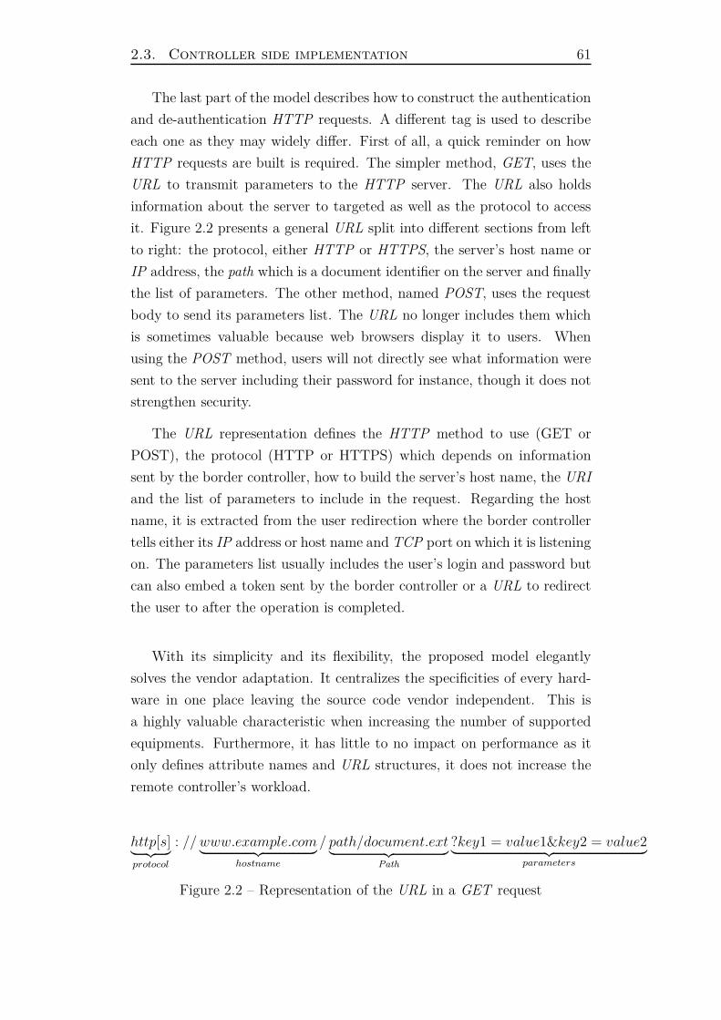
2.3. Controller side implementation 61
The last part of the model describes how to construct the authentication
and de-authentication HTTP requests. A different tag is used to describe
each one as they may widely differ. First of all, a quick reminder on how
HTTP requests are built is required. The simpler method, GET, uses the
URL to transmit parameters to the HTTP server. The URL also holds
information about the server to targeted as well as the protocol to access
it. Figure 2.2 presents a general URL split into different sections from left
to right: the protocol, either HTTP or HTTPS, the server’s host name or
IP address, the path which is a document identifier on the server and finally
the list of parameters. The other method, named POST, uses the request
body to send its parameters list. The URL no longer includes them which
is sometimes valuable because web browsers display it to users. When
using the POST method, users will not directly see what information were
sent to the server including their password for instance, though it does not
strengthen security.
The URL representation defines the HTTP method to use (GET or
POST), the protocol (HTTP or HTTPS) which depends on information
sent by the border controller, how to build the server’s host name, the URI
and the list of parameters to include in the request. Regarding the host
name, it is extracted from the user redirection where the border controller
tells either its IP address or host name and TCP port on which it is listening
on. The parameters list usually includes the user’s login and password but
can also embed a token sent by the border controller or a URL to redirect
the user to after the operation is completed.
With its simplicity and its flexibility, the proposed model elegantly
solves the vendor adaptation. It centralizes the specificities of every hard-
ware in one place leaving the source code vendor independent. This is
a highly valuable characteristic when increasing the number of supported
equipments. Furthermore, it has little to no impact on performance as it
only defines attribute names and URL structures, it does not increase the
remote controller’s workload.
http[s]︸ ︷︷ ︸
protocol
: // www.example.com︸ ︷︷ ︸
hostname
/ path/document.ext︸ ︷︷ ︸
Path
?key1 = value1&key2 = value2︸ ︷︷ ︸
parameters
Figure 2.2 – Representation of the URL in a GET request
62 Chapter 2. A mutualized approach
2.3.2 Improving user experience and data gathering
Currently, the implementation allows end-users to get a remote captive
portal, authenticate against their local border controller and disconnect
from it. This minimal set of features is enough to control users in a private
network. Though functional, it is not user friendly enough. Indeed in the
event where the authentication request is rejected, it is difficult to provide
the right feedback to the user about the triggered error. Because the border
controller performs the authentication request using the RADIUS protocol,
only a yes/no answer, including an optional reason message is sent back by
the server. This reason message is by no mean self explanatory for every-
body: foreign language, technical information or error codes. That is why
the captive portal should be the one to display a comprehensive feedback
understandable by a multitude of people. Section 2.2.3 also outlined that
border controllers do not always send the RADIUS reason message when
authentication fails leaving the captive portal powerless to display anything
but a generic error.
Implementing a user pre-authentication prior to building the HTTP
request to post user’s credentials on the border controller addresses this
limitation. Indeed the captive portal is able to trigger an authentication
without starting a new session and able to retrieve the resulting error
code. Depending on it, the portal can send the proper feedback to the
user and prevent the border controller from triggering an authentication
request which will fail. Figure 2.3 is an updated version of the interactions
between the border and the remote controllers. The pre-authentication is
done right after the user sends its credentials to the captive portal.
Moreover, the pre-authentication is a great opportunity to implement
the BYOD filtering. As only the captive portal is able to retrieve these
information from the User-Agent attribute, it is the only place where they
can be checked and stored if needed. The enhanced implementation uses the
captive portal in order to fulfill to BYOD filtering as well as storing these
information into the session database so they are available for reporting
and statistics.
2.4 Summary
This chapter presented an innovative architecture in which a network
access controller is mutualized between multiple distant networks or sites.
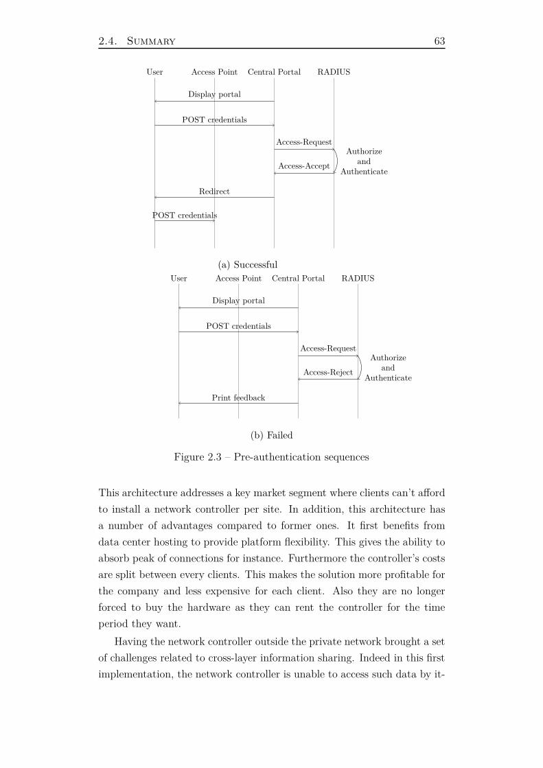
2.4. Summary 63
User Access Point Central Portal RADIUS
Display portal
POST credentials
Access-RequestAuthorize
andAuthenticate
Access-Accept
Redirect
POST credentials
(a) Successful
User Access Point Central Portal RADIUS
Display portal
POST credentials
Access-RequestAuthorize
andAuthenticate
Access-Reject
Print feedback
(b) Failed
Figure 2.3 – Pre-authentication sequences
This architecture addresses a key market segment where clients can’t afford
to install a network controller per site. In addition, this architecture has
a number of advantages compared to former ones. It first benefits from
data center hosting to provide platform flexibility. This gives the ability to
absorb peak of connections for instance. Furthermore the controller’s costs
are split between every clients. This makes the solution more profitable for
the company and less expensive for each client. Also they are no longer
forced to buy the hardware as they can rent the controller for the time
period they want.
Having the network controller outside the private network brought a set
of challenges related to cross-layer information sharing. Indeed in this first
implementation, the network controller is unable to access such data by it-
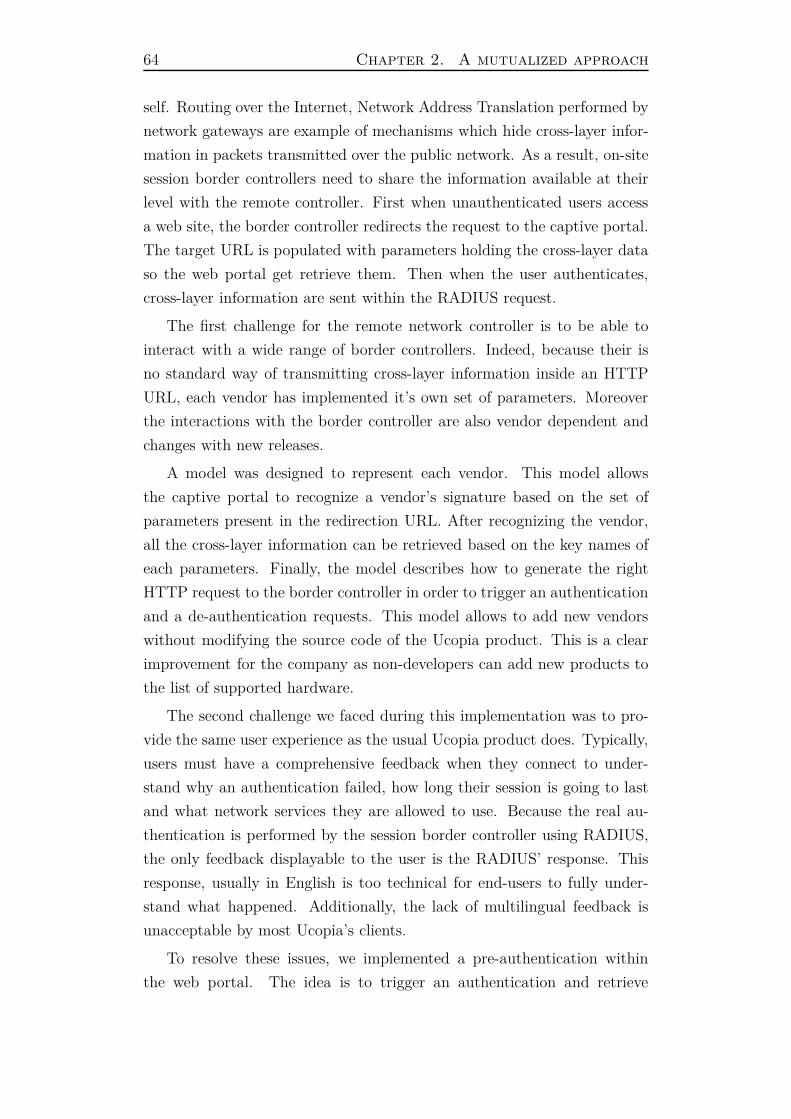
64 Chapter 2. A mutualized approach
self. Routing over the Internet, Network Address Translation performed by
network gateways are example of mechanisms which hide cross-layer infor-
mation in packets transmitted over the public network. As a result, on-site
session border controllers need to share the information available at their
level with the remote controller. First when unauthenticated users access
a web site, the border controller redirects the request to the captive portal.
The target URL is populated with parameters holding the cross-layer data
so the web portal get retrieve them. Then when the user authenticates,
cross-layer information are sent within the RADIUS request.
The first challenge for the remote network controller is to be able to
interact with a wide range of border controllers. Indeed, because their is
no standard way of transmitting cross-layer information inside an HTTP
URL, each vendor has implemented it’s own set of parameters. Moreover
the interactions with the border controller are also vendor dependent and
changes with new releases.
A model was designed to represent each vendor. This model allows
the captive portal to recognize a vendor’s signature based on the set of
parameters present in the redirection URL. After recognizing the vendor,
all the cross-layer information can be retrieved based on the key names of
each parameters. Finally, the model describes how to generate the right
HTTP request to the border controller in order to trigger an authentication
and a de-authentication requests. This model allows to add new vendors
without modifying the source code of the Ucopia product. This is a clear
improvement for the company as non-developers can add new products to
the list of supported hardware.
The second challenge we faced during this implementation was to pro-
vide the same user experience as the usual Ucopia product does. Typically,
users must have a comprehensive feedback when they connect to under-
stand why an authentication failed, how long their session is going to last
and what network services they are allowed to use. Because the real au-
thentication is performed by the session border controller using RADIUS,
the only feedback displayable to the user is the RADIUS’ response. This
response, usually in English is too technical for end-users to fully under-
stand what happened. Additionally, the lack of multilingual feedback is
unacceptable by most Ucopia’s clients.
To resolve these issues, we implemented a pre-authentication within
the web portal. The idea is to trigger an authentication and retrieve
2.4. Summary 65
the feedback sent by the Ucopia authentication server. This feedback is
already translated in many languages and not too technical. This pre-
authentication is also the opportunity to share valuable information held
inside the client’s HTTP request. For example, the User-Agent field con-
tains lots of information about the user device including Operating System,
browser type and version etc. . . These information allow to differentiate the
network controller based on the user device’s type (BYOD). The implemen-
tation of this pre-authentication phase extensively used cross-layer infor-
mation in order to identify a user device between the captive portal and
the RADIUS server. Indeed, in order to retrieve information on both sides,
common knowledge must be shared (e.g. the device MAC address).
Finally it is worth mentioning that this remote network controller has
already been deployed in various Ucopia projects including stadiums and
train stations. The code was released in the 5.0 Ucopia version in 2014 and
entirely developed by the author of this thesis.
This implementation is based on specialized hardware implementing
custom HTTP requests to share cross-layer information with a remote cap-
tive portal and trigger user authentications. Because these hardware can
not be controlled by the remote controller directly, new features are hard to
develop. Moreover the configuration of such architecture is harden by the
fact that every border controller needs to have all the user profile informa-
tion in terms of network services for example. The next chapter presents
a different approach to implement this architecture using SDN equipments
instead. It aims at addressing the limitations of the current implementa-
tion regarding the interactions between the controllers, both for the user
authentication and network filtering.

Chapter 3
An SDN approach
Software-Defined Networking (SDN) [57] [52] [37] is a recent networking
paradigm that decouples the data plan from the control plan [34]. SDN ar-
chitectures aim to be manageable and dynamic by enabling a programmable
control plan and a hardware abstraction. Network equipments communi-
cate via SDN protocols with other computers which dictate how the net-
work traffic has to be forwarded. Today, only a fraction of network equip-
ments in the market is SDN capable but this is changing rapidly especially
regarding Wi-Fi access points where a number of vendors integrates some
SDN capabilities [53] [9]. Looking at the growth of Wi-Fi access points
and their transformation into SDN equipments, it is fair to assume that in
few years, most Wi-Fi hotspots will be SDN enabled.
In that regard, if border controllers become SDN equipments, one could
control how they forward packets from a remote location which is some-
how what was done in the previous architecture. Here though, hardware
is abstracted and communications between the equipment and a controller
are made using a standard protocol. Implementing a border controller only
with SDN equipments would address the problems raised in the last chap-
ter: vendor agnostic and runtime control of the forwarding plan. Moreover,
assuming the majority of network equipments will be SDN capable in the
next few years, any kind of hardware would be able to act as a border con-
troller which is a clear improvement compared to the current architecture
where specialized hardware are required.
This chapter is also the opportunity to present a concrete implementa-
tion of the cross-layering framework using SDN equipments. It presents a
novel mechanism to modify HTTP payloads in order to include cross-layer
information. The implementation focuses on HTTP but can be extended
68 Chapter 3. An SDN approach
to support any kind of network protocols. Additionally, it is transparent for
equipments on the network as it only involves SDN equipments and their
controller.
This chapter is arranged as follow: first section 3.1 discusses the pros
and cons of this approach and put it in perspective with novel technolo-
gies like Network Function Virtualization (NFV) [8] [42]. Then section 3.2
presents the OpenFlow protocol both for its technical aspects and its limi-
tations. Section 3.3 and 3.5 explain how these limitations can be overcome
in order to implement a captive portal redirection.
3.1 Discussion
Piloting network equipments is not something new, vendors often use
their own protocols to remotely configure and manage them from a network
controller. It is especially true with Wi-Fi equipments. Of course, the con-
troller is part of the vendor’s package when he sells the equipments and is
only compatible with them. With this technique, vendors force customers
to use the equipments of a single brand for their entire architecture. Other
non-proprietary protocols have emerged outside the Wi-Fi world such as
NETCONF [60] [45]. This protocol developed by the IETF aims to pro-
vide a standard way of pushing and retrieving configurations from network
equipments regardless of their brand. The raising of SDN capable hardware
in Wi-Fi access points opens up new opportunities to build heterogeneous
architectures controlled from a single controller.
Despite the keen interest developed around SDN, building a border
controller with generic hardware is hard. Indeed, everything has to be im-
plemented in software, from the captive portal redirection to the firewalling
rules. Furthermore, SDN protocols were not built around the idea of con-
trolling user access but rather about the way of forwarding packets inside
an equipment. This limits protocols features to only networking purposes.
Network Function Virtualization is another novel technology rapidly
growing in the networking community. The idea is to instantiate on de-
mand any kind of Virtual Network Function (VNF) on top of an hypervisor.
It leverages all the benefits brought by virtualization to migrate functions
from one place to another inside the network, provide high availability and
flexibility. A VNF is the implementation of a network function, for instance
it could be embodied as a firewall, a switch, a router or even a session border
3.2. OpenFlow 69
controller. Though to instantiate a VNF, one has to have control over an
hypervisor inside the network. This hypervisor is part of the Network Func-
tion Virtualization Infrastructure which gathered all pieces of the network
along with the access methods to equipments. Such infrastructure is hard
to deploy and maintain, it requires hardware, data centers and expertise.
That is why NFV is suited for carrier-grade service providers: they already
have buildings, expertise and hardware, furthermore they have control over
the entire network.
In the context of private networks, it is unlikely to find hypervisors in-
side a customer’s network. Even then, there is little chances that a third
party can instantiate its own VNF on top of it. It requires a strong integra-
tion in terms of orchestration process, trust and maintenance. A solution
can emerge in the near future using set-top boxes provided by Internet
provides in order to host a “session border controller”VNF. These hard-
ware are completely controlled by the service provider and can easily be
integrated as part of its NFVI. This solution might require to update some
hardware to include virtualization support as well as an hypervisor.
Service providers are only interested in providing a service to their cus-
tomers. For instance they provide Wi-Fi hotspots via Internet boxes only
accessible for their clients. Furthermore, the owner of the Internet access
has no control what so ever on the hotspot provided by its box. This
is not the kind of solutions presented in this thesis, the client should be
able to customize and control it’s network. As long as NFV remains a
carrier-grade provider technology, it seems difficult to build a independent
customizable network access solution VNF. This is not irremediable in the
future but for now, SDN -based solution seems better suited for the purpose
of implementing a private network access controller.
Next section presents the OpenFlow protocol which defines a set of
interfaces for network equipments to delegate their forwarding decisions to
a remote controller.
3.2 OpenFlow
OpenFlow [54], LISP [24] [30] or OpenDaylight [31] are examples of
SDN protocol implementations, that can help simplify and improve network
guest access configuration and management. OpenFlow is open source,
popular and mature, all of which makes it an ideal candidate to support
70 Chapter 3. An SDN approach
the following proposed architecture.
3.2.1 Protocol overview
Although it was originally designed for network experimentation, Open-
Flow is now implemented by various hardware vendors including HP, Ju-
niper and IBM [62]. OpenFlow does not rely on any proprietary feature.
It abstracts the underlying hardware design and aims to be adopted by a
large number of equipment vendors. At its simplest level, the protocol lets
an OpenFlow switch be configured by an OpenFlow controller. The Open-
Flow switch requests and receives traffic rules from the controller over a
trusted Transport Layer Security (TLS) tunnel. TLS implements both an
end-to-end encryption of data payloads but also a mutual authentication
between the switch and the controller using signed certificates. A set of
default rules is configured by the remote controller on the switch, which
processes and enforces these rules in its packet forwarding table.
Internally, the OpenFlow switch uses a flow table and a standardized
interface to add and remove flow entries. A flow is a set of packets which
share the same properties. A flow entry consists of a matching rule and a set
of actions. OpenFlow specification requires the switch to act on protocols
of layer 2 to 4 of the OSI model [35] including Ethernet, VLAN 802.1q,
MPLS , IP, TCP and UDP.
OpenFlow rules are grouped into chained rule tables. Each packet is
processed against the matching rules of the current table. If no rule is
matched, the packet is passed to the following rule table. If the packet
matches a rule, the processing can either jump to another rule table or a
specific set of actions can be executed. As an example, actions associated
with the rule and a matched packet could be to:
— drop the packets from the flow,
— send the packets on a particular port of the equipment,
— apply bandwidth limitation to the flow,
— modify header’s fields including IP addresses, VLAN tag, . . .
Whenever a packet can not be matched by any existing rules, the switch
triggers a table miss action sending the raw, or part of the packet to its
controller. After analysis, the controller tells the switch what to do with this
packet by inserting a new entry in the flow table. Control information is also
associated with each rule. For example, the controller may indicate when
a rule expires, which is an efficient way to grant network access to a device
3.2. OpenFlow 71
for a limited period of time. OpenFlow switches also provide accounting
information for each flow allowing the controller to retrieve valuable data
at any time.
OpenFlow leverages the usage of TCP in order to have bi-directional
communication between switches and the controller. Because the switches
initiate the TCP session, it traverses NAT s and firewalls in between. This
property allows a controller to modify a switch’s forwarding table whenever
needed. It addresses the lack of interactions of the previous architecture.
3.2.2 Packet matching
Each OpenFlow switch has a number of flow tables. They contain rules
to match and take action on incoming packets. Whenever a rule matches,
its actions are pushed into the packet’s action set. If at one point the
packet has to be sent on an outgoing port, these actions will be applied.
A rule might also affect the internal processing of a packet by jumping to
another table rule, dropping the packet or sending it. A switch can send a
packet on one or many physical ports as well as a number of virtual ports
which have special meanings. For instance there is a virtual port for the
communication link with the controller, to send raw packets, or another
one to flood all the ports of the switch.
Figure 3.1 shows how an incoming packet is matched through the dif-
ferent table of the switch. It starts with an empty action set and as rules
are matched, it gets filled up with actions. In the end, when the packet is
about to be sent, all the actions of the set are applied and the packet is
sent onto an outgoing port.
Matching rules are composed by a number of header fields-expression
tuples. The switch applies the expression on the packet’s header field’s
value. If every expressions match, it triggers a rule match. A wide range
of headers can be used in OpenFlow rules including almost everything in
common protocols from layer 2 to layer 4: Ethernet, IP, TCP, ICMP,
. . . . Regarding actions, switches have to be able to modify a subset of the
packet’s header fields including addresses, port numbers, pushing/pooping
a VLAN or MPLS tag. These packet’s modifications might break the
checksum of protocols like IP or TCP, hence the switch must re-compute
them.
Finally, the controller exposes public API in order to create/modify and
retrieve information from flows. They are often referred as Northbound

72 Chapter 3. An SDN approach
Packet InTable
0Table
1Table
nExecute
Action set
Packet Out
ActionSet = {}
Ingressport
OpenFlow Switch
Figure 3.1 – Table matching of an incoming packet inside an OpenFlowswitch [35]
API. Given a controller, an external application (e.g. a network controller)
can learn the network topology and create flows on specific switches.
3.2.3 Limitations
OpenFlow is a very powerful protocol which enables real network instru-
mentalization regardless of the hardware. In order to be easily integrated,
the specification does not require the hardware to implement advanced net-
working features. Indeed only protocols’ headers are matched and modified.
On the other hand, current equipments are able today to perform ad-
vanced networking treatments such as service classification using DPI tech-
niques. Fine-grained filtering on web services as well as advanced reporting
can be achieved. Moreover, session border controller are often in charge of
intercepting user flows in order to force the usage of an applicative proxy or
perform HTTP redirection for unauthenticated users. OpenFlow is limited
compared to such hardware because it is unable to instrumentalize upper
layer protocols.
This is problematic in the present context. Not only the captive portal
must be able to differentiate user devices belonging to the same private
networks like in chapter 2, but also now, it needs to notify the OpenFlow
controller about newly authenticated users. Indeed the controller takes
decision based on packets network information only. To build a network
access solution, the system must be able to bind an identity to a device
as presented in chapter 1. Lacking common device identifier prevents the
captive portal from pushing access rules to the controller.
The HTTP redirection presented in chapter 2 would solve that issue.
It provides enough information to the captive portal to identify devices be-
longing the same private network. Despite OpenFlow being unable to per-
form such redirection, it gives the ability to implement custom processing

3.3. Proposal to overcome OpenFlow limitations 73
inside the controller. This is the main challenge of this thesis, implement
the captive portal redirection containing cross-layer network information
only using OpenFlow equipments. The implementation focuses on the cap-
tive portal redirection but can be extended to any kind of use cases. Next
section presents how OpenFlow limitations can be overcome in order to
properly implement the redirection of users.
3.3 Proposal to overcome OpenFlow limita-
tions
Last section outlined the need for border controllers to implement a
captive portal redirection including the user device’s network information
so they are available to the captive portal. This step is absolutely crucial
to provide enough information to allow the notification of the OpenFlow
control so it can open network access to newly connected users.
Despite OpenFlow equipments being capable to redirect traffic to other
hosts, for instance by modifying the destination IP address of a flow, pack-
ets sent on the Internet see their source IP address being masked. Figure
3.2 describes this mechanism, packets sent by a network device have their
destination address re-written by the OpenFlow equipment and forwarded
to the Internet gateway. The gateway then sends the packet with its public
IP address so the server can reply to a routable address. Leveraging this
technique, one can intercept the user web traffic and redirect it to its web
server implementing a web portal redirection. But again, the web server
lacks network information about the user device.
To provide enough information to the web portal, unauthenticated user
devices are redirected using HTTP. This redirection includes all necessary
data to identify the device uniquely and retrieve its location. In the current
architecture, both the OpenFlow equipment and the controller have access
to topology information. That is because the switch is directly in the path
of packets and it sends raw packets to its controller to let it decide how to
forward them. This capability is leveraged to tunnel network flows from
the switch to its controller. This way the controller can intercept any kind
of traffic from a switch. The technical details of this proposal are explained
in section 3.4.2. The implementation aims at intercepting HTTP traffic
sent by unauthorized devices, tunnel them to the controller and reply with
a custom HTTP redirection.
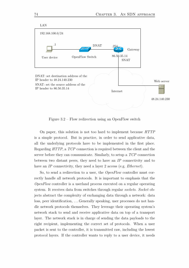
74 Chapter 3. An SDN approach
Internet
LAN
192.168.100.0/24
.1
48.24.140.230
.254
86.50.35.14User device OpenFlow Switch
Gateway
DNAT
SNAT
DNAT: set destination address of theIP header to 48.24.140.230
SNAT: set the source address of theIP header to 86.50.35.14
Web server
Figure 3.2 – Flow redirection using an OpenFlow switch
On paper, this solution is not too hard to implement because HTTP
is a simple protocol. But in practice, in order to send applicative data,
all the underlying protocols have to be implemented in the first place.
Regarding HTTP, a TCP connection is required between the client and the
server before they can communicate. Similarly, to setup a TCP connection
between two distant peers, they need to have an IP connectivity and to
have an IP connectivity, they need a layer 2 access (e.g. Ethernet).
So, to send a redirection to a user, the OpenFlow controller must cor-
rectly handle all network protocols. It is important to emphasis that the
OpenFlow controller is a userland process executed on a regular operating
system. It receives data from switches through regular sockets. Socket ob-
jects abstract the complexity of exchanging data through a network: data
loss, peer identification, . . . Generally speaking, user processes do not han-
dle network protocols themselves. They leverage their operating system’s
network stack to send and receive applicative data on top of a transport
layer. The network stack is in charge of sending the data payloads to the
right recipient, implementing the correct set of protocols. When a user
packet is sent to the controller, it is transmitted raw, including the lowest
protocol layers. If the controller wants to reply to a user device, it needs
3.4. OpenFlow network tunnel 75
to implement all layers correctly.
Because network protocols are very hard to implement properly, trying
to implement even a small portion inside a userland process constitutes a
huge amount of work. Instead the OpenFlow controller can act as a network
tunnel termination receiving raw packets from OpenFlow messages and
forwarding them directly onto a network interface. Furthermore, it has to
redirect the traffic onto a specific host which implements a web server. This
way HTTP can be correctly implemented. The web server is configured to
reply with an HTTP redirection to any request it receives. Finally the
controller identifies the redirection and modifies the target URL in order
to append the device network information.
Next section presents the implementation details of the network tunnel
over OpenFlow proposal. Then section 3.5 presents how flows are modified
by the controller to implement the captive portal redirection.
3.4 OpenFlow network tunnel
Network tunneling is a widely spread technique to encapsulate a pro-
tocol in another one. For instance in order to transition from IPv4 to
IPv6 networks, 6to4 tunnels encapsulate an IPv6 header inside an IPv4
one so the IPv6 payload can be routed inside an IPv4 network. Another
example of network tunnels is Virtual Private Networks (VPN) in which IP
payloads are encapsulated inside a protocol able to cross other networks.
Service providers can provide VPN s over IP whereas individuals usually
use VPN s over TCP or UDP.
The current proposal uses an OpenFlow switch to intercept network
flows and encapsulate them inside OpenFlow packet-in messages. The
switch sends them through the encrypted channel to its controller. Upon
reception, the controller decapsulates the packets from the OpenFlow mes-
sages. These packets can not be sent directly onto a local interface because
their destination MAC and IP addresses are populated by the user device.
The information they hold are only relevant from the device point of view
so the controller has to modify them accordingly. Namely the destination
MAC and IP addresses must be replaced by the ones of the targeted server.
Because OpenFlow is implemented over TCP, or SCTP, the structure
of packets sent by the switch to its controller looks like this:
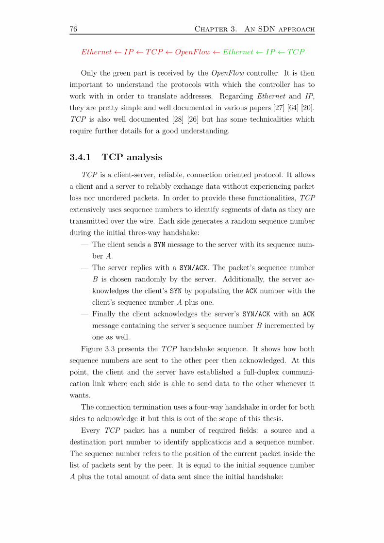
76 Chapter 3. An SDN approach
Ethernet← IP ← TCP ← OpenF low ← Ethernet← IP ← TCP
Only the green part is received by the OpenFlow controller. It is then
important to understand the protocols with which the controller has to
work with in order to translate addresses. Regarding Ethernet and IP,
they are pretty simple and well documented in various papers [27] [64] [20].
TCP is also well documented [28] [26] but has some technicalities which
require further details for a good understanding.
3.4.1 TCP analysis
TCP is a client-server, reliable, connection oriented protocol. It allows
a client and a server to reliably exchange data without experiencing packet
loss nor unordered packets. In order to provide these functionalities, TCP
extensively uses sequence numbers to identify segments of data as they are
transmitted over the wire. Each side generates a random sequence number
during the initial three-way handshake:
— The client sends a SYN message to the server with its sequence num-
ber A.
— The server replies with a SYN/ACK. The packet’s sequence number
B is chosen randomly by the server. Additionally, the server ac-
knowledges the client’s SYN by populating the ACK number with the
client’s sequence number A plus one.
— Finally the client acknowledges the server’s SYN/ACK with an ACK
message containing the server’s sequence number B incremented by
one as well.
Figure 3.3 presents the TCP handshake sequence. It shows how both
sequence numbers are sent to the other peer then acknowledged. At this
point, the client and the server have established a full-duplex communi-
cation link where each side is able to send data to the other whenever it
wants.
The connection termination uses a four-way handshake in order for both
sides to acknowledge it but this is out of the scope of this thesis.
Every TCP packet has a number of required fields: a source and a
destination port number to identify applications and a sequence number.
The sequence number refers to the position of the current packet inside the
list of packets sent by the peer. It is equal to the initial sequence number
A plus the total amount of data sent since the initial handshake:
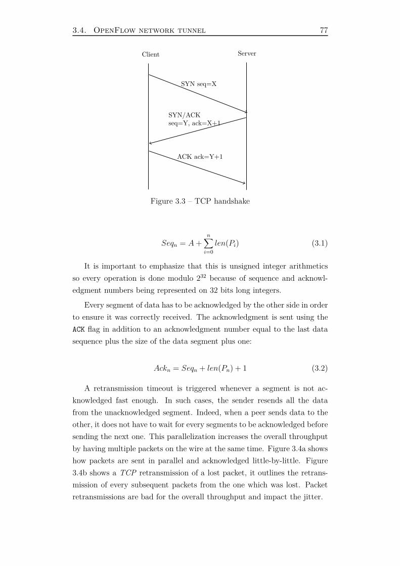
3.4. OpenFlow network tunnel 77
SYN seq=X
SYN/ACKseq=Y, ack=X+1
ACK ack=Y+1
Client Server
Figure 3.3 – TCP handshake
Seqn = A +n∑
i=0
len(Pi) (3.1)
It is important to emphasize that this is unsigned integer arithmetics
so every operation is done modulo 232 because of sequence and acknowl-
edgment numbers being represented on 32 bits long integers.
Every segment of data has to be acknowledged by the other side in order
to ensure it was correctly received. The acknowledgment is sent using the
ACK flag in addition to an acknowledgment number equal to the last data
sequence plus the size of the data segment plus one:
Ackn = Seqn + len(Pn) + 1 (3.2)
A retransmission timeout is triggered whenever a segment is not ac-
knowledged fast enough. In such cases, the sender resends all the data
from the unacknowledged segment. Indeed, when a peer sends data to the
other, it does not have to wait for every segments to be acknowledged before
sending the next one. This parallelization increases the overall throughput
by having multiple packets on the wire at the same time. Figure 3.4a shows
how packets are sent in parallel and acknowledged little-by-little. Figure
3.4b shows a TCP retransmission of a lost packet, it outlines the retrans-
mission of every subsequent packets from the one which was lost. Packet
retransmissions are bad for the overall throughput and impact the jitter.
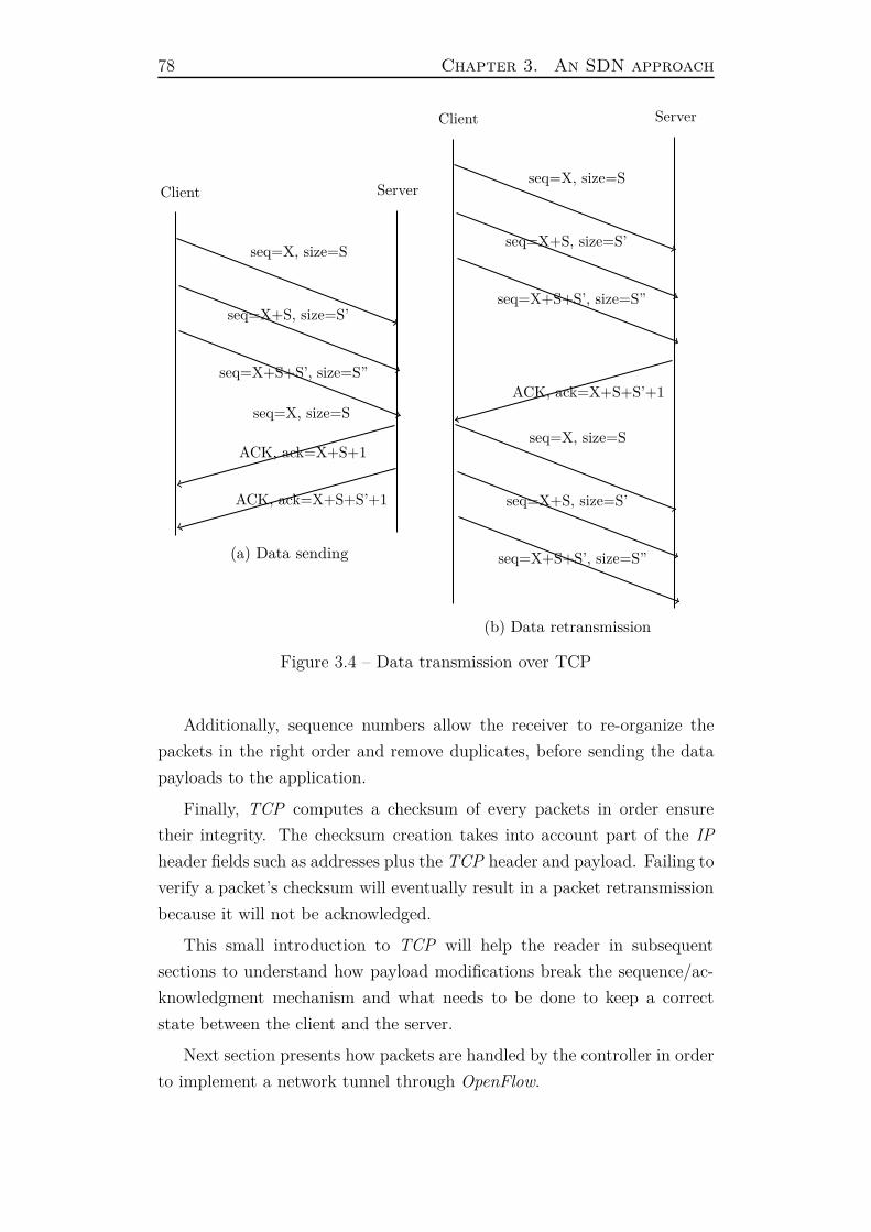
78 Chapter 3. An SDN approach
Client Server
seq=X, size=S
seq=X+S, size=S’
seq=X+S+S’, size=S”
seq=X, size=S
ACK, ack=X+S+1
ACK, ack=X+S+S’+1
(a) Data sending
Client Server
seq=X, size=S
seq=X+S, size=S’
seq=X+S+S’, size=S”
ACK, ack=X+S+S’+1
seq=X, size=S
seq=X+S, size=S’
seq=X+S+S’, size=S”
(b) Data retransmission
Figure 3.4 – Data transmission over TCP
Additionally, sequence numbers allow the receiver to re-organize the
packets in the right order and remove duplicates, before sending the data
payloads to the application.
Finally, TCP computes a checksum of every packets in order ensure
their integrity. The checksum creation takes into account part of the IP
header fields such as addresses plus the TCP header and payload. Failing to
verify a packet’s checksum will eventually result in a packet retransmission
because it will not be acknowledged.
This small introduction to TCP will help the reader in subsequent
sections to understand how payload modifications break the sequence/ac-
knowledgment mechanism and what needs to be done to keep a correct
state between the client and the server.
Next section presents how packets are handled by the controller in order
to implement a network tunnel through OpenFlow.
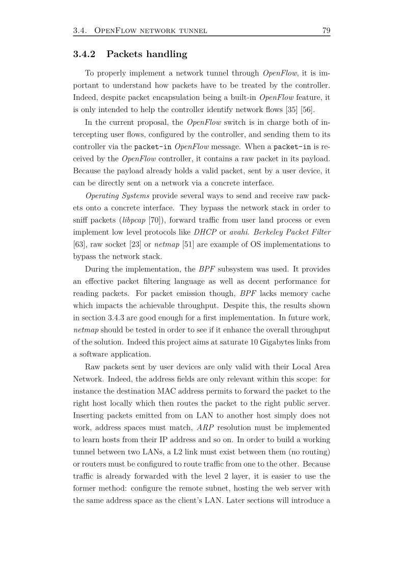
3.4. OpenFlow network tunnel 79
3.4.2 Packets handling
To properly implement a network tunnel through OpenFlow, it is im-
portant to understand how packets have to be treated by the controller.
Indeed, despite packet encapsulation being a built-in OpenFlow feature, it
is only intended to help the controller identify network flows [35] [56].
In the current proposal, the OpenFlow switch is in charge both of in-
tercepting user flows, configured by the controller, and sending them to its
controller via the packet-in OpenFlow message. When a packet-in is re-
ceived by the OpenFlow controller, it contains a raw packet in its payload.
Because the payload already holds a valid packet, sent by a user device, it
can be directly sent on a network via a concrete interface.
Operating Systems provide several ways to send and receive raw pack-
ets onto a concrete interface. They bypass the network stack in order to
sniff packets (libpcap [70]), forward traffic from user land process or even
implement low level protocols like DHCP or avahi. Berkeley Packet Filter
[63], raw socket [23] or netmap [51] are example of OS implementations to
bypass the network stack.
During the implementation, the BPF subsystem was used. It provides
an effective packet filtering language as well as decent performance for
reading packets. For packet emission though, BPF lacks memory cache
which impacts the achievable throughput. Despite this, the results shown
in section 3.4.3 are good enough for a first implementation. In future work,
netmap should be tested in order to see if it enhance the overall throughput
of the solution. Indeed this project aims at saturate 10 Gigabytes links from
a software application.
Raw packets sent by user devices are only valid with their Local Area
Network. Indeed, the address fields are only relevant within this scope: for
instance the destination MAC address permits to forward the packet to the
right host locally which then routes the packet to the right public server.
Inserting packets emitted from on LAN to another host simply does not
work, address spaces must match, ARP resolution must be implemented
to learn hosts from their IP address and so on. In order to build a working
tunnel between two LANs, a L2 link must exist between them (no routing)
or routers must be configured to route traffic from one to the other. Because
traffic is already forwarded with the level 2 layer, it is easier to use the
former method: configure the remote subnet, hosting the web server with
the same address space as the client’s LAN. Later sections will introduce a
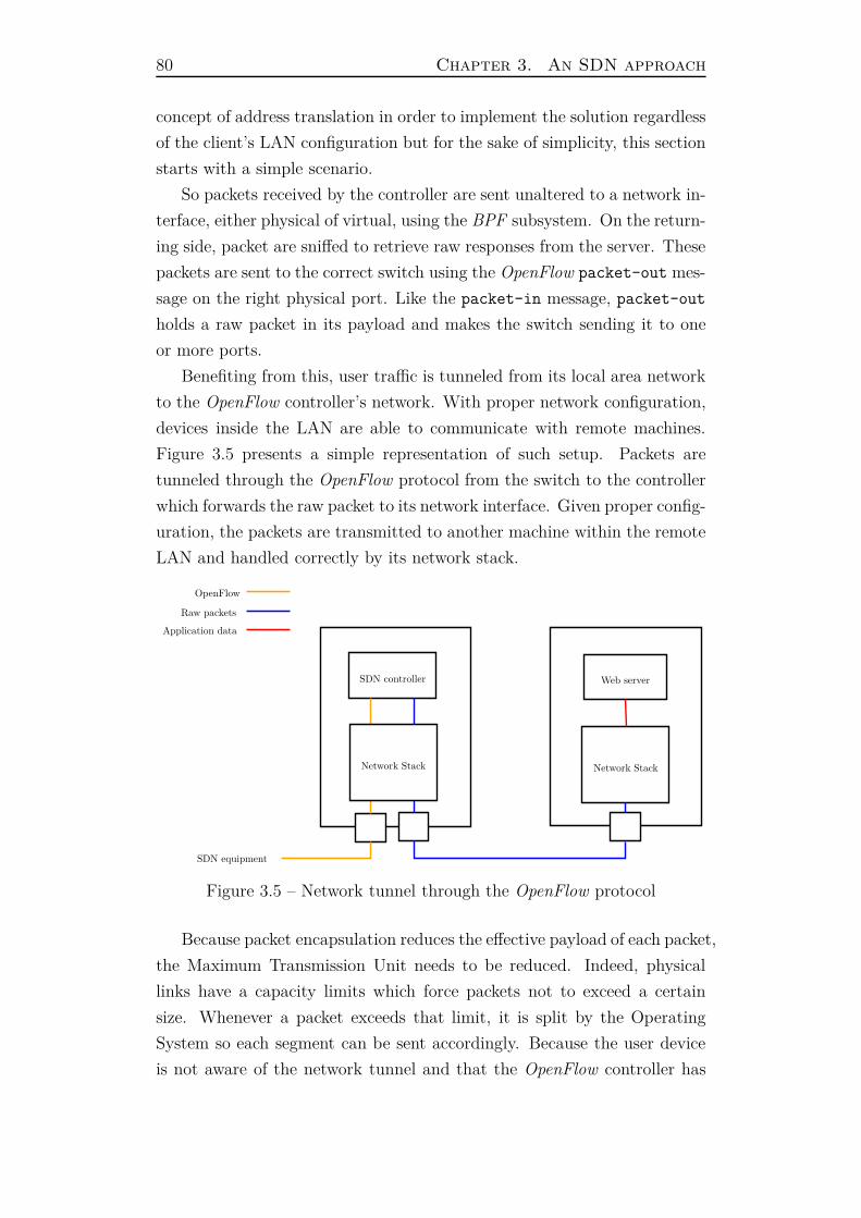
80 Chapter 3. An SDN approach
concept of address translation in order to implement the solution regardless
of the client’s LAN configuration but for the sake of simplicity, this section
starts with a simple scenario.
So packets received by the controller are sent unaltered to a network in-
terface, either physical of virtual, using the BPF subsystem. On the return-
ing side, packet are sniffed to retrieve raw responses from the server. These
packets are sent to the correct switch using the OpenFlow packet-out mes-
sage on the right physical port. Like the packet-in message, packet-out
holds a raw packet in its payload and makes the switch sending it to one
or more ports.
Benefiting from this, user traffic is tunneled from its local area network
to the OpenFlow controller’s network. With proper network configuration,
devices inside the LAN are able to communicate with remote machines.
Figure 3.5 presents a simple representation of such setup. Packets are
tunneled through the OpenFlow protocol from the switch to the controller
which forwards the raw packet to its network interface. Given proper config-
uration, the packets are transmitted to another machine within the remote
LAN and handled correctly by its network stack.
SDN controller Web server
Network Stack
SDN equipment
OpenFlow
Network Stack
Raw packets
Application data
Figure 3.5 – Network tunnel through the OpenFlow protocol
Because packet encapsulation reduces the effective payload of each packet,
the Maximum Transmission Unit needs to be reduced. Indeed, physical
links have a capacity limits which force packets not to exceed a certain
size. Whenever a packet exceeds that limit, it is split by the Operating
System so each segment can be sent accordingly. Because the user device
is not aware of the network tunnel and that the OpenFlow controller has

3.4. OpenFlow network tunnel 81
no means to configure its MTU, the TCP’s Maximum Segment Size is set
by the server. That TCP’s option allows both peers to advertise the maxi-
mum size of the TCP payloads to transmit in order to reduce the packets’
fragmentation [65]. Additionally because a user process slows down the
forwarding of packets [50], it is important to ensure enough bandwidth is
delivered by the present tunnel. Indeed it is intended to scale in production
to up to thousands of concurrent users for a single controller. A bandwidth
test was setup to study the implementation. The main objective is to reach
the controller’s limit as it is the bottleneck of the architecture.
3.4.3 Performance measurements
Tunneling traffic always decreases bandwidth because it reduces the
effective data payload. By encapsulating traffic inside an applicative pro-
tocol like OpenFlow which is already wrapped inside an encryption layer,
the amount of user data carried in packets is highly reduced. Moreover
every user packets is forwarded by the OpenFlow controller, a user process,
which is slow.
The test involves ten machines with different hardware, from lightweight
equipments to heavy bare metal servers. Table 3.1 summarizes the hard-
ware capabilities along with the number of servers of each type. Each one
of them runs an OpenVSwitch [16] instance (v2.3.1) controlled by an Open-
Daylight [31] controller. The controller implements our proposal, it uses the
BPF subsystem to bypass its network stack. As a side note, the controller
runs FreeBSD version 10.1 and the other equipments run GNU/Linux with
Debian 7. Additionally, the experiment needs to be isolated from the con-
crete local network. On the controller side, the applicative server is hosted
as a virtual machine on the FreeBSD system using its hypervisor: bhyve.
On the other hand, the mininet [69] project allowed to create virtual net-
works inside each machine. Mininet leverages the Linux kernel namespace
to create interconnection between virtual interfaces in order to simulate a
real network. Each mininet network is controllable by an OpenFlow con-
troller thanks to the OpenVSwitch instance.
To generate traffic and saturate the tunnel link, the iperf [11] program
was used. It is a lightweight yet powerful and flexible program which gen-
erates TCP or UDP traffic between a client and a server. To ensure the
tunnel link is saturated, each CPU of each machine executes an iperf in-
stance. The TCP Maximum Segment Size [43] [47] is set to 1400 to prevent
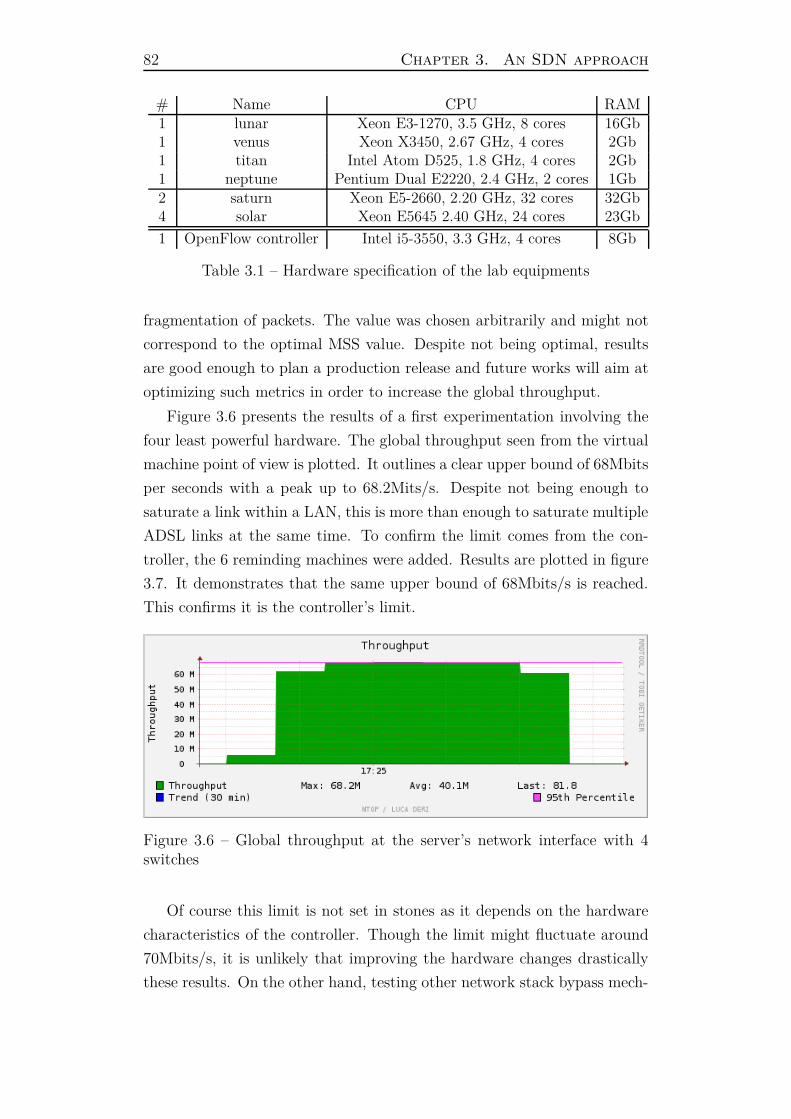
82 Chapter 3. An SDN approach
# Name CPU RAM1 lunar Xeon E3-1270, 3.5 GHz, 8 cores 16Gb1 venus Xeon X3450, 2.67 GHz, 4 cores 2Gb1 titan Intel Atom D525, 1.8 GHz, 4 cores 2Gb1 neptune Pentium Dual E2220, 2.4 GHz, 2 cores 1Gb2 saturn Xeon E5-2660, 2.20 GHz, 32 cores 32Gb4 solar Xeon E5645 2.40 GHz, 24 cores 23Gb
1 OpenFlow controller Intel i5-3550, 3.3 GHz, 4 cores 8Gb
Table 3.1 – Hardware specification of the lab equipments
fragmentation of packets. The value was chosen arbitrarily and might not
correspond to the optimal MSS value. Despite not being optimal, results
are good enough to plan a production release and future works will aim at
optimizing such metrics in order to increase the global throughput.
Figure 3.6 presents the results of a first experimentation involving the
four least powerful hardware. The global throughput seen from the virtual
machine point of view is plotted. It outlines a clear upper bound of 68Mbits
per seconds with a peak up to 68.2Mits/s. Despite not being enough to
saturate a link within a LAN, this is more than enough to saturate multiple
ADSL links at the same time. To confirm the limit comes from the con-
troller, the 6 reminding machines were added. Results are plotted in figure
3.7. It demonstrates that the same upper bound of 68Mbits/s is reached.
This confirms it is the controller’s limit.
Figure 3.6 – Global throughput at the server’s network interface with 4switches
Of course this limit is not set in stones as it depends on the hardware
characteristics of the controller. Though the limit might fluctuate around
70Mbits/s, it is unlikely that improving the hardware changes drastically
these results. On the other hand, testing other network stack bypass mech-
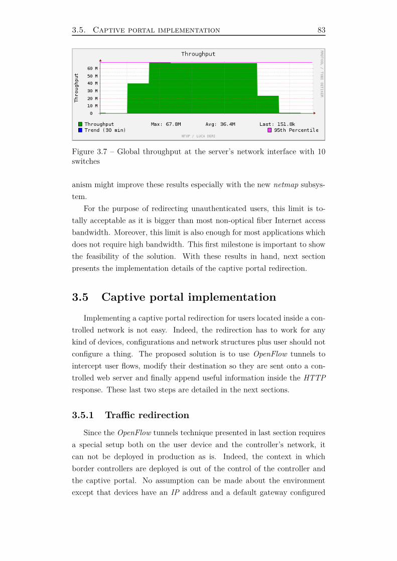
3.5. Captive portal implementation 83
Figure 3.7 – Global throughput at the server’s network interface with 10switches
anism might improve these results especially with the new netmap subsys-
tem.
For the purpose of redirecting unauthenticated users, this limit is to-
tally acceptable as it is bigger than most non-optical fiber Internet access
bandwidth. Moreover, this limit is also enough for most applications which
does not require high bandwidth. This first milestone is important to show
the feasibility of the solution. With these results in hand, next section
presents the implementation details of the captive portal redirection.
3.5 Captive portal implementation
Implementing a captive portal redirection for users located inside a con-
trolled network is not easy. Indeed, the redirection has to work for any
kind of devices, configurations and network structures plus user should not
configure a thing. The proposed solution is to use OpenFlow tunnels to
intercept user flows, modify their destination so they are sent onto a con-
trolled web server and finally append useful information inside the HTTP
response. These last two steps are detailed in the next sections.
3.5.1 Traffic redirection
Since the OpenFlow tunnels technique presented in last section requires
a special setup both on the user device and the controller’s network, it
can not be deployed in production as is. Indeed, the context in which
border controllers are deployed is out of the control of the controller and
the captive portal. No assumption can be made about the environment
except that devices have an IP address and a default gateway configured

84 Chapter 3. An SDN approach
(along with a working ARP resolution). In this situation, to implement
a captive portal redirection, the proposed solution has to work with any
kind of network configuration. Because it is not possible to adapt the
remote controller’s network to every networks, it is proposed to implement
a Network Address Translation by modifying user flows’ addresses.
When a device connects to a remote server (outside its LAN ), it sends
a packet to its gateway with the following information:
Source DestinationEthernet MACdevice MACgateway
IP IPdevice IPserver
In order for the web server’s network stack to accept packets, the des-
tination MAC and IP address must be his.
Addresses are modified by the controller in the following manner:
— The destination IP and MAC addresses of packets emitted by users
are replaced by the IPwebserver MACwebserver.
— The destination IP and MAC addresses of packets returning to users
are replaced by IPdevice MACdevice.
— The source IP address of returning packets is replaced by IPserver
which is the initial destination IP address so the device thinks the
reply comes from the server it requested.
When header fields are modified by an intermediate equipment here
the OpenFlow controller), it invalidates protocols’ checksums. Typically,
IP, TCP and UDP use checksums [17] to protect themselves from data
corruption. Thus the controller has to be careful about recomputing each
packet’s checksum when one or more fields are modified within a packet.
Moreover one must be extra-careful with TCP which includes part of the
IP header in its checksum (including addresses). Hence in the present
situation, both the IP and TCP checksums must be re-computed on every
modified packets.
Now that the controller is able to intercept user traffic and redirect it
to a chosen server, it becomes feasible to implement an HTTP redirection.
Following section presents how the web server is configured in order to
implement the HTTP layer.

3.5. Captive portal implementation 85
3.5.2 Web server
Following the same guidelines about not re-implementing basic pro-
tocols seen in section 3.3, using an HTTP server to implement that layer
seems obvious. They are highly configurable and efficient to reply to HTTP
requests.
In the present situation, the web server is only intended to redirect every
requests using a return code. A couple HTTP codes fulfill this goal, namely
301 and 302. The former tells the client that the document he asked for
has moved permanently to a different location whereas the latter notifies
that the document has moved temporarily. When a web browser receives
one of these responses to a request, it will follow the URL present in the
Location HTTP header field. If the redirection is permanent, later requests
to the initial URL will result in an internal redirection. As an example if a
browser receives a permanent redirection when it asks for www.google.com,
it will not be possible for the user to access this website anymore. That is
why the preferred response code is 302 here.
Additionally because Operating Systems do not provide standard API
to access low level network information of a peer such as it’s MAC address,
the Apache web server is unable to populate the URL with the correct GET
parameters. Moreover, it has little information about the network topology
making it a weak point to decide the zone in which the user is connected.
That zone allows to redirect the user to the correct web portal with the
correct visual. For these reasons, we propose to delegate these tasks to the
OpenFlow controller. Indeed it has all the information in hands to take
care of this job.
In this proposal, the web server is only in charge of setting up and main-
taining TCP states as well as crafting HTTP responses. Traffic emitted
from user devices is intercepted and injected onto a controlled web server.
It replies to any HTTP requests with a redirection.
Next section details how the OpenFlow controller modifies part of the
data flow in order to insert the user device network information inside the
redirection URL.
3.5.3 OpenFlow controller
When the web server replies to a request, the OpenFlow controller modi-
fies part of the response. It is important to remember that it’s the controller
86 Chapter 3. An SDN approach
who forwards every packets from OpenFlow switches to the web server. In
order to modify the response, the controller first needs to identify it. The
implementation searches at a specific offset of the TCP payload for the
"Location:" string. To speed up the lookup, only packets with a non-zero
payload and the PUSH flag set are taken into account. The offset remains
fixed for a specific web server, indeed it replies with the same response all
the time. Hence it is easy to calibrate the controller during its startup
sequence in order to find the correct location’s offset.
Once the response is identified, the controller chooses a captive portal
to redirect the user to. The configuration details are out of the scope of this
paper but as an example users connected to the backery SSID might be
redirected to the /zone/backery URI whereas others to /zone/welcome.
Parameters about the user device and any others are then appended to the
URI. A sample URL might look like this:
http://portal.com/z/b/?mac=00:43:21:f3:32:43&ip=10.10.1.1
The crafted URL is then inserted in place of the "Location:" field’s value
replacing the dummy URL. The modified packet is then sent to the user
device. Because the size of the original packet is modified, TCP sequence
and acknowledgment numbers are corrupted. Indeed TCP uses the size of
transmitted packets to increase sequence numbers and acknowledge data
segments. Here a man-in-the-middle, the controller, has modified the data
being sent by the server. Hence the client received something different from
what the server sent.
Next section details how the controller deals with these numbers in order
to keep both sides synchronized.
3.5.4 Dealing with TCP
The URL modification introduced a size difference between the original
packet sent by the server, with the sequence number Seqi and the size leni,
and the one received by the client. This difference is noted ∆s.
When the client acknowledges the packet, it uses the equation (3.2) to
generate the following acknowledgment number:
Ack′
i = Seqi + leni + ∆s + 1 (3.3)
3.5. Captive portal implementation 87
The problem lays in the fact that the server expects the data to be
acknowledged until:
Acki = Seqi + leni + 1 (3.4)
RFC 793 which defines the TCP protocol states that a peer should reset
the connection if it receives data out its receiving window that is between
the last acknowledged segment and the last packet’s sequence number plus
its size:
Acklast < Acki < Seqn + lenn (3.5)
As a result, the acknowledgment sent by the client must be modified in
order to be part of the server’s receiving window. Formally, the acknowl-
edgment number has to be decreased by ∆s:
Ack′′
i = Ack′
i −∆s (3.6)
= Seqi + leni + 1 + ∆s −∆s (3.7)
= Seqi + leni + 1 (3.8)
= Acki (3.9)
When the server receives the acknowledgment, it sees the correct num-
ber Acki.
On the other hand, the sequence numbers are also biased by the packet’s
modification. Indeed the next packet sent by the server will have a sequence
number equal to:
Seqi+1 = Seqi + leni (3.10)
whereas the client expects:
Seq′
i+1 = Seqi + leni + ∆s (3.11)
Reusing the operation done on acknowledgment numbers, the controller
modifies the sequence numbers of packets emitted by the server in the
following manner:
88 Chapter 3. An SDN approach
Seq′′
i+1 = Seqi+1 + ∆s (3.12)
= Seqi + leni + ∆s (3.13)
= Seq′
i+1 (3.14)
These two simple operations synchronize the sequence and acknowledg-
ment numbers between the two TCP peers. This allows to modify the TCP
payload in order to instrumentalize applicative protocols.
Corner cases exist when the redirection packet is not big enough to add
all the data required. The packet must then be split into multiple ones
and the controller has to deal accordingly with the acknowledgments (an
algorithm is presented in appendix)
Next section presents the performance analysis of the portal redirection
implementation.
3.5.5 Performance
To measure how well the implementation performs, the first thing to
look at is the maximum rate at which HTTP requests are redirected. The
redirection rate is later noted ρ. Similarly to the bandwidth experiment
presented in section 3.4.3, the same set of 10 machines concurrently run
an HTTP bencher called ab [1]. The web server is configured using the
RedirectMatch directive [2] to create redirection responses.
The first three figures 3.8 show ρ over time for the three least power-
ful hardware independently. Valuable information lays in these plots as
they show stable rate over time. They also demonstrate a high correla-
tion between ρ and the CPU grade. Indeed a factor 3 exists between the
venus machine (figure 3.8c) and the other two (figures 3.8a 3.8b). Even
for lightweight hardware, the implementation is able to redirect up to 150
requests per seconds. This is largely enough to handle thousands of concur-
rent users as shown in figure 3.9. The maximum redirection rate is below
70 requests per seconds.
Additionally, a measurement of the requests’ latency was made during
the same test. The idea is to ensure that the overhead introduced by the
controller is not too big for end-users. Figure 3.10 presents box plots of the
request latency for each hardware. The titan is highly impacted compared
to the others because of its poor hardware capacity (the benchmark uses
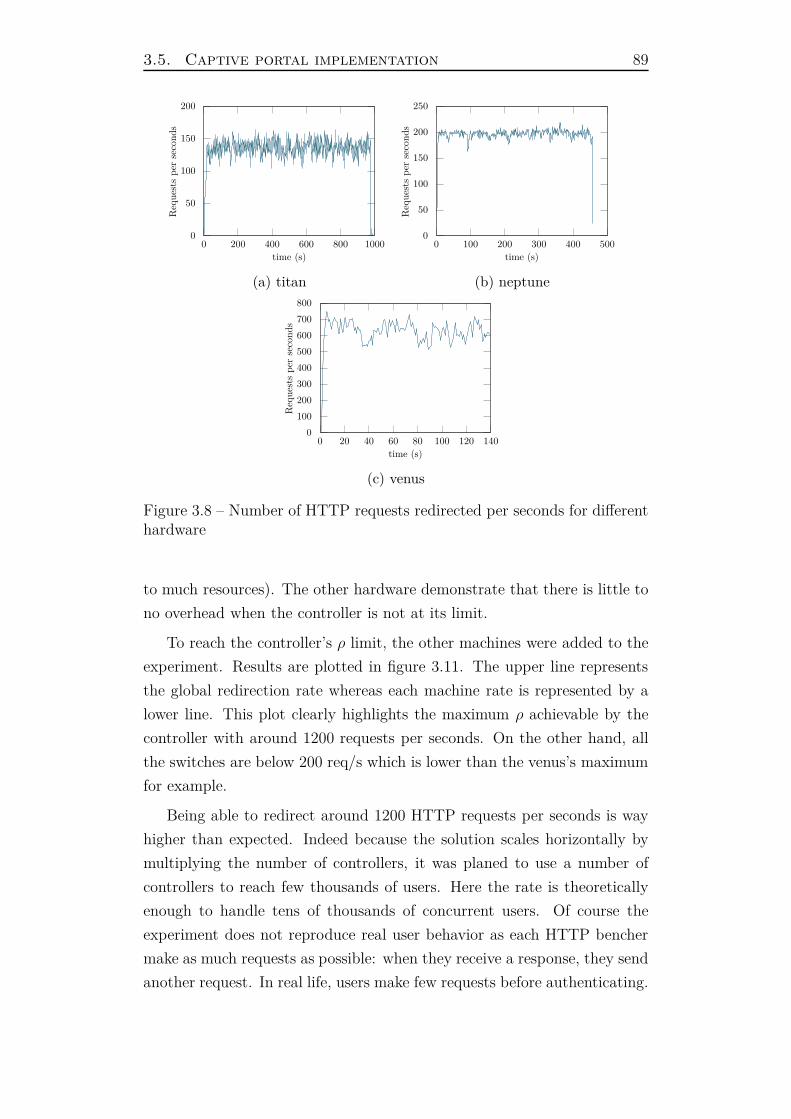
3.5. Captive portal implementation 89
0
50
100
150
200
0 200 400 600 800 1000
Req
ues
tsp
erse
conds
time (s)
(a) titan
0
50
100
150
200
250
0 100 200 300 400 500
Req
ues
tsp
erse
conds
time (s)
(b) neptune
0
100
200
300
400
500
600
700
800
0 20 40 60 80 100 120 140
Req
ues
tsp
erse
conds
time (s)
(c) venus
Figure 3.8 – Number of HTTP requests redirected per seconds for differenthardware
to much resources). The other hardware demonstrate that there is little to
no overhead when the controller is not at its limit.
To reach the controller’s ρ limit, the other machines were added to the
experiment. Results are plotted in figure 3.11. The upper line represents
the global redirection rate whereas each machine rate is represented by a
lower line. This plot clearly highlights the maximum ρ achievable by the
controller with around 1200 requests per seconds. On the other hand, all
the switches are below 200 req/s which is lower than the venus’s maximum
for example.
Being able to redirect around 1200 HTTP requests per seconds is way
higher than expected. Indeed because the solution scales horizontally by
multiplying the number of controllers, it was planed to use a number of
controllers to reach few thousands of users. Here the rate is theoretically
enough to handle tens of thousands of concurrent users. Of course the
experiment does not reproduce real user behavior as each HTTP bencher
make as much requests as possible: when they receive a response, they send
another request. In real life, users make few requests before authenticating.
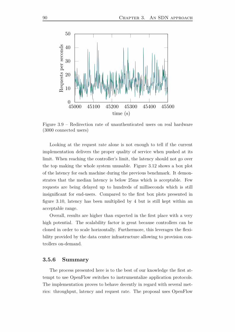
90 Chapter 3. An SDN approach
0
10
20
30
40
50
45000 45100 45200 45300 45400 45500
Req
ues
tsp
erse
conds
time (s)
Figure 3.9 – Redirection rate of unauthenticated users on real hardware(3000 connected users)
Looking at the request rate alone is not enough to tell if the current
implementation delivers the proper quality of service when pushed at its
limit. When reaching the controller’s limit, the latency should not go over
the top making the whole system unusable. Figure 3.12 shows a box plot
of the latency for each machine during the previous benchmark. It demon-
strates that the median latency is below 25ms which is acceptable. Few
requests are being delayed up to hundreds of milliseconds which is still
insignificant for end-users. Compared to the first box plots presented in
figure 3.10, latency has been multiplied by 4 but is still kept within an
acceptable range.
Overall, results are higher than expected in the first place with a very
high potential. The scalability factor is great because controllers can be
cloned in order to scale horizontally. Furthermore, this leverages the flexi-
bility provided by the data center infrastructure allowing to provision con-
trollers on-demand.
3.5.6 Summary
The process presented here is to the best of our knowledge the first at-
tempt to use OpenFlow switches to instrumentalize application protocols.
The implementation proves to behave decently in regard with several met-
rics: throughput, latency and request rate. The proposal uses OpenFlow

3.5. Captive portal implementation 91
0
50
100
150
200
venus titan neptune
late
ncy
(ms)
Figure 3.10 – Box plots of request latencies for the three different hardware
equipments to intercept and send raw packets emitted by user devices to
an OpenFlow controller. In order to exempt a complete network stack im-
plementation within the controller, the patented solution demonstrates the
feasibility of having another network stack to take care of the user traffic.
The implementation permits to redirect user traffic to an external cap-
tive web portal. The key factor here is that the redirection response is
modified by the controller to add the user device network information. It
is an example of cross-layering via OpenFlow. These information are cru-
cial for the remote captive portal to differentiate devices within a private
network and notify the controller about newly authorized devices. The so-
lution meets the requirements of being transparent for end-users and web
browser independent. Moreover new features can be implemented within
the controller: for instance, the redirection URL can be signed to prevent
modification from end-users. This is a clear improvement over current im-
plementations. These new features are implemented inside the controller
only. Traditionally, such mechanism is absent from network equipments
and would require an upgrade of the embedded software to include this
feature. In the present situation, one can imagine common APIs between
the OpenFlow controller and the remote captive portal to exchange keying
materials to sign information passing by the user browser.
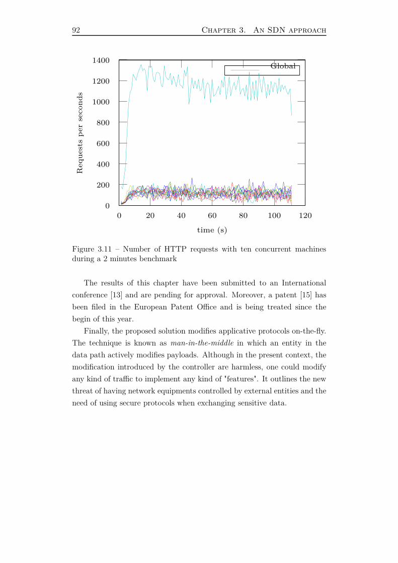
92 Chapter 3. An SDN approach
0
200
400
600
800
1000
1200
1400
0 20 40 60 80 100 120
Req
uest
sp
er
seco
nd
s
time (s)
Global
Figure 3.11 – Number of HTTP requests with ten concurrent machinesduring a 2 minutes benchmark
The results of this chapter have been submitted to an International
conference [13] and are pending for approval. Moreover, a patent [15] has
been filed in the European Patent Office and is being treated since the
begin of this year.
Finally, the proposed solution modifies applicative protocols on-the-fly.
The technique is known as man-in-the-middle in which an entity in the
data path actively modifies payloads. Although in the present context, the
modification introduced by the controller are harmless, one could modify
any kind of traffic to implement any kind of "features". It outlines the new
threat of having network equipments controlled by external entities and the
need of using secure protocols when exchanging sensitive data.
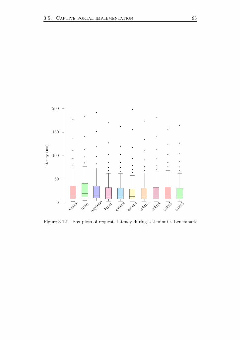
3.5. Captive portal implementation 93
0
50
100
150
200
venu
s
titan
nept
une
luna
r
satu
rn
satu
rn
solar3
solar4
solar5
solar6
late
ncy
(ms)
Figure 3.12 – Box plots of requests latency during a 2 minutes benchmark


Conclusion and Perspectives
This manuscript has been a great opportunity to present the need of ac-
cessing cross-layer information for network applications. It demonstrated,
through a concrete example, that these pieces of information are key when
implementing custom network behavior. Additionally, most remote appli-
cations can not directly access such cross-layer information. The presen-
tation focused on a specific network application: controlling user access
in private networks. Chapter 1 presented the current state of the art re-
garding user authentication and network access control. It gave a solid
background to fully understand the ins and outs of controlling user access:
who accesses what ? User authentication responds to the former question
whereas cross-layer information permit to build advanced firewalling rules.
The keystone which tight them together is the ability for the solution to
bind the user identity to its device. A number of authentication methods
were presented in this chapter giving different kinds of trust about the user
recognition with a trade off between security and user-friendliness. Addi-
tionally, multiple network protocols to transport user authentication were
presented as well as techniques to filter network traffic based on cross-layer
information.
Then a novel architecture was presented in chapter 2. It permits to
mutualize a network controller by hosting it in a public Cloud. It leverages
the usage of lightweight Wi-Fi access-points on site to perform the physical
network filtering of users as well as the captive portal enforcement. In order
for the captive portal to differentiate devices within the same Local Area
Network, the on site equipments add network information inside an HTTP
redirection: when an unauthorized device tries to perform an HTTP request
outside the network, the equipment redirects it to the captive portal. The
target URL is populated with additional parameters to send to the captive
portal. This is a practical example of sharing cross-layer information.
To authenticate users, the session border controllers perform a RADIUS
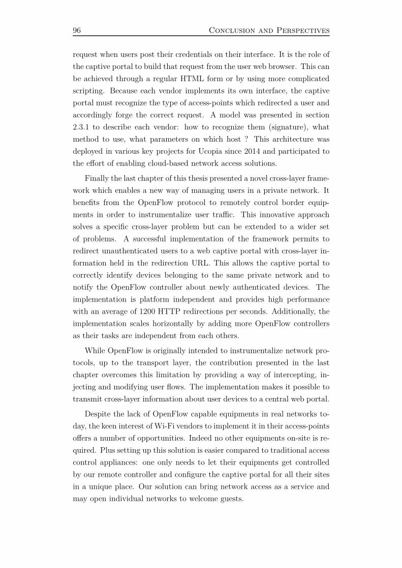
96 Conclusion and Perspectives
request when users post their credentials on their interface. It is the role of
the captive portal to build that request from the user web browser. This can
be achieved through a regular HTML form or by using more complicated
scripting. Because each vendor implements its own interface, the captive
portal must recognize the type of access-points which redirected a user and
accordingly forge the correct request. A model was presented in section
2.3.1 to describe each vendor: how to recognize them (signature), what
method to use, what parameters on which host ? This architecture was
deployed in various key projects for Ucopia since 2014 and participated to
the effort of enabling cloud-based network access solutions.
Finally the last chapter of this thesis presented a novel cross-layer frame-
work which enables a new way of managing users in a private network. It
benefits from the OpenFlow protocol to remotely control border equip-
ments in order to instrumentalize user traffic. This innovative approach
solves a specific cross-layer problem but can be extended to a wider set
of problems. A successful implementation of the framework permits to
redirect unauthenticated users to a web captive portal with cross-layer in-
formation held in the redirection URL. This allows the captive portal to
correctly identify devices belonging to the same private network and to
notify the OpenFlow controller about newly authenticated devices. The
implementation is platform independent and provides high performance
with an average of 1200 HTTP redirections per seconds. Additionally, the
implementation scales horizontally by adding more OpenFlow controllers
as their tasks are independent from each others.
While OpenFlow is originally intended to instrumentalize network pro-
tocols, up to the transport layer, the contribution presented in the last
chapter overcomes this limitation by providing a way of intercepting, in-
jecting and modifying user flows. The implementation makes it possible to
transmit cross-layer information about user devices to a central web portal.
Despite the lack of OpenFlow capable equipments in real networks to-
day, the keen interest of Wi-Fi vendors to implement it in their access-points
offers a number of opportunities. Indeed no other equipments on-site is re-
quired. Plus setting up this solution is easier compared to traditional access
control appliances: one only needs to let their equipments get controlled
by our remote controller and configure the captive portal for all their sites
in a unique place. Our solution can bring network access as a service and
may open individual networks to welcome guests.

Conclusion and Perspectives 97
In parallel, lots of effort have been made within the Ucopia’s R&D team
to improve the Ucopia solution’s performance. Indeed, it is a key factor
in this architecture as it provides the web portal, the user database and
the authentication server. Ucopia solution is now able to handle more than
20000 concurrent users by itself and aims at reaching 100000 next year.
This thesis’ outcomes have brought great benefit to the company both
immediate and in the long term. The architecture described in chapter 2
has already been deployed in various projects and the market’s demand is
increasing. Regarding the OpenFlow story, the company now has a first
foot inside the SDN world with a very promising patent.
Still both architectures lack features in order to be fully compliant with
customer requests. The main problem is that the user logs are no longer
recorded: indeed with no controller on-site, it’s hard to store the user’s
activity. One proposal is to use the information sent by the access-points
via the syslog protocol in order to retrieve visited URLs or even packets
logs. An implementation of this is being tested but still has poor per-
formances. Moreover, the syslog messages are sent in plain text over the
Internet possibly exposing sensitive user data.
On the other hand, the OpenFlow architecture implementation is only
partially complete. Though the main technical lock has been resolved, an
other challenge remains: building up a set of firewalling rules within a
constraint environment. Indeed among the OpenFlow equipment diversity,
small hardware have limited memory. In such cases, the flow table size
might be tight to hold a large number of rules. Future work aims at studying
that problem and finding ways to decrease the number of rules to control
users. One proposition is to aggregate rules used by different profiles.
This thesis has open lots of perspectives both on the industrial and
scientific sides. First of all the implementation of a complete prototype for
network access control with OpenFlow equipments would highly benefits
the Ucopia company by opening a new market full of opportunities. Second
of all, Network Function Virtualization could bring even more flexibility to
our proposal and might fill the gaps of the current implementation.
Mainly given the orchestration capabilities of SDN protocols over NFV,
it becomes feasible to instantiate Network Functions on demand from an
SDN controller. This could allow the implementation of lawful functions
whenever needed in order to be compliant with law requirements. Moreover

98 Conclusion and Perspectives
network functions can implement capabilities absent from SDN equipments
and extend easily a given setup.
We believe that NFV gives a promising perspective for network access
control and that a thesis on that subject can make a lot of sense.
Appendix A
Dealing with over sized packets
In the last chapter of this thesis, a presentation of an OpenDaylight
bundle was made. It is in charge of forwarding raw traffic coming from an
OpenFlow equipment to a dedicated server and identifying HTTP redirec-
tions sent to the user. These packets are then modified to inject valuable
data about the user device. This attributes list might grow the packet
beyond the MTU. This would result in a packet drop at the switch.
To cope with this situation, the controller must detect and split such
packets before sending them to the client. Following acknowledgments must
be dropped by the controller until the last one is received. Indeed, the
client will acknowledge multiple segments whereas the server sent only one.
Formally, when the server modifies a packet, it computes the last expected
acknowledgment number ACKlast. Then it splits the packet into chunks
which fit the MTU and sends them in order to the client. For every following
acknowledgments (sent by the client), the controller checks that they are
lesser than ACKlast and drop them. Whenever the last acknowledgment is
received, the controller forward it (minus ∆s) to the server.
Algorithm 1 presents the function which handles all received packets.
First the function gathers the recorded state of the TCP stream from
packet’s information (Ethernet and IP addresses, TCP source port num-
ber). This state holds valuable information about the client and the server
in order to perform the NAT as well as ACKlast when a packet is modified
inside the stream. Then the function branches depending on the side of the
packet: when it comes from the server, it tests of it needs to modify the
packet and if so modifies it and sends it in chunks (if needed). When the
packet comes from a client, it verifies that it acknowledges up to ACKlast
before forwarding it to the server. Of course the concrete implementation of

100 Appendix A. Dealing with over sized packets
this function does more processing to detect new TCP connections, 4-way
termination handshake or perform NAT correctly.
Algorithm 1 Over sized packets
function receivePacket(buffer packet)state← getState(packet) ⊲ Get recorded state from packetif isFromServer(packet) then
if shouldModify(packet) thenpacket′
← modify(packet)∆s ← size(packet′)− size(packet)state.ACKlast ← packet.SEQ + ∆s + 1i← 0while size(packet′) > MTU do
i← i + send(packet′[i : i + MTU ]
elsesend(packet)
else ⊲ Packet comes from a clientif state.ACKlast > 0 then
if packet.ACK < state.ACKlast thenreturn P ACKET_IGNORED
elsepacket.ACK ← packet.ACK −∆s
send(packet)
return P ACKET_CONSUMED
The algorithm heavily relays on the configured MTU between the client
and the server but this parameter is never transmitted directly and does
not take into account the OpenFlow tunnel. Thankfully, a TCP option
exists to bound the maximum size of the payload. It is called the MSS
(Maximum Segment Size). In general, the MSS reflects the MTU at the
TCP layer: MSS = MTU − size(IP ) − size(TCP ). In our situation,
the controller is able to read the MSS during the 3-way handshake at the
beginning of every connection. Additionally, it can modify this value if it
is too high to fit inside the OpenFlow tunnel.
List of Figures
1.1 Simple password-based authentication between a user Bob and an authentication server
1.2 A simple Public Key Infrastructure . . . . . . . . . . . . . . 25
1.3 Sequence diagram of a public key certificate based authentication 26
1.4 Session border controller in a Local Area Network . . . . . . 29
1.5 Unauthenticated device trying to access the network through 802.1X 33
1.6 Chaining of RADIUS proxies which route requests to the right service provider 37
1.7 Representation of the OSI stack . . . . . . . . . . . . . . . . 42
1.8 Network stacks collaboration . . . . . . . . . . . . . . . . . . 42
1.9 Basic firewalling rule based on TCP destination port . . . . 43
1.10 Web proxy interception . . . . . . . . . . . . . . . . . . . . . 46
2.1 Sequence diagram of a user device authentication . . . . . . 54
2.2 Representation of the URL in a GET request . . . . . . . . 61
2.3 Pre-authentication sequences . . . . . . . . . . . . . . . . . . 63
3.1 Table matching of an incoming packet inside an OpenFlow switch [35] 72
3.2 Flow redirection using an OpenFlow switch . . . . . . . . . . 74
3.3 TCP handshake . . . . . . . . . . . . . . . . . . . . . . . . . 77
3.4 Data transmission over TCP . . . . . . . . . . . . . . . . . . 78
3.5 Network tunnel through the OpenFlow protocol . . . . . . . 80
3.6 Global throughput at the server’s network interface with 4 switches 82
3.7 Global throughput at the server’s network interface with 10 switches 83
3.8 Number of HTTP requests redirected per seconds for different hardware 89
3.9 Redirection rate of unauthenticated users on real hardware (3000 connected users) 90
3.10 Box plots of request latencies for the three different hardware 91
3.11 Number of HTTP requests with ten concurrent machines during a 2 minutes benchmark
3.12 Box plots of requests latency during a 2 minutes benchmark 93


List of Tables
1.1 Hash results of of similar input strings for three different algorithms 19
3.1 Hardware specification of the lab equipments . . . . . . . . . 82


Bibliography
[1] ab - Apache HTTP server benchmarking tool. Technical report, The
Apache Software Foundation.
[2] Apache HTTP Server Documentation. Technical report, The Apache
Software Foundation.
[3] Service Name and Transport Protocol Port Number Registry. Techni-
cal report, IANA.
[4] Squid web proxy project.
[5] The SquidGuard project.
[6] ISO/IEC 7498. Technical report, ISO, 1994.
[7] Subscriber Identity Module - Mobile Equipment Interface Specifica-
tion. Technical report, European Telecommunications Standards In-
stitute, 1994.
[8] White paper on "Network Functions Virtualisation". Technical report,
SDN and OpenFlow World Congress, 2012.
[9] SDN for Wi-Fi OpenFlow-enabling the wireless LAN can bring new
levels of agility. White paper, 2014.
[10] Hervé Aıache, Vania Conan, Jérémie Leguay, and Mikaël Levy. Xian:
Cross-layer interface for wireless ad hoc networks. MEDHOCNET
2006, 2006.
[11] Jon Dugan Ajay Tirumala, Feng Qin. Iperf: The TCP/UDP band-
width measurement tool. 2005.
[12] Nadarajah Asokan, Valtteri Niemi, and Kaisa Nyberg. Man-in-the-
middle in tunnelled authentication protocols. In Security Protocols,
pages 28–41. Springer, 2005.
[13] G. Pujolle B. Villain, J. Ridoux. SDN Based Network Access Con-
troller: a First Milestone. To be Published, 2015.
106 Bibliography
[14] J. Rotrou B. Villain, J. Ridoux. Mutualized OpenFlow Architecture
for Network Access Management. Cloud’Net, 2014.
[15] P. Borras B. Villain, J. Rotrou. Procédé de contrôle d’accès à un réseau
privé. Technical report, Ucopia - UPMC, 2015.
[16] Justin Pettit Ben Pfaff, Keith Amidon. Extending Networking into
the Virtualization Layer. ACM Workshop in Hot Topics in Networks,
2009.
[17] James G. Wendt Brian M. Dowling, Christian J. Warling. Hardware
checksum assist for network protocol stacks. Technical report, Hewlett-
Packard, 1997.
[18] Raffaele Bruno, Marco Conti, and Enrico Gregori. Mesh networks:
commodity multihop ad hoc networks. Communications Magazine,
IEEE, 43(3):123–131, 2005.
[19] A. Rubens and W. Simpson C. Rigney, S. Willens. Remote Authenti-
cation Dial In User Service (RADIUS). Technical report, IETF, 2000.
[20] T. Chiueh C. Venkatramani. Design, implementation, and evaluation
of a software-based real-time Ethernet protocol. SIGCOMM ’95, 1995.
[21] Marco Conti, Silvia Giordano, Gaia Maselli, and Giovanni Turi. Mo-
bileman: Mobile metropolitan ad hoc networks. In Personal Wireless
Communications, pages 169–174. Springer, 2003.
[22] Marco Conti, Gaia Maselli, Giovanni Turi, and Silvia Giordano. Cross-
layering in mobile ad hoc network design. Computer, 37(2):48–51,
2004.
[23] S. Muir D. Culler, A. Bavier. Operating System Support for Planetary-
Scale Network Services. First USENIX Symposium on Networked Sys-
tems Design and Implementation, 2004.
[24] D. Meyer D. Farinacci, V. Fuller. The Locator/ID Separation Protocol
(LISP). Technical report, IETF, 2013.
[25] D. Rauschmayer. ADSL/Vdsl Principles: A Practical and Precise
Study of Asymmetric Digital Subscriber Lines and Very High Speed
Digital Subscriber Lines. 1998.
[26] J. Romkey and H. Salwen D.D. Clark, V. Jacobson. An analysis of
TCP processing overhead. IEEE Communications Magazine, 1989.
[27] Defense Advanced Research Projects Agency. Internet Protocol. Tech-
nical report, University of Southern California, 1981.
Bibliography 107
[28] Defense Advanced Research Projects Agency. Transmission Control
Protocol. Technical report, University of Southern California, 1981.
[29] Gianni A Di Caro, Silvia Giordano, Mirko Kulig, Davide Lenzarini,
Alessandro Puiatti, and Francois Schwitter. A cross-layering and au-
tonomic approach to optimized seamless handover. In WONS 2006:
Third Annual Conference on Wireless On-demand Network Systems
and Services, pages 104–113, 2006.
[30] Patrick Raad Dung Phun Chi, Stefano Secci. An Open Control-Plane
Implementation for LISP Networks. IC-NIDC, 2012.
[31] Takashi Egawa, Shin ichiro Hayano, and Fabian Schneider. Standard-
izations of sdn and its practical implementation. Technical report,
2014.
[32] Eric Thompson. MD5 collisions and the impact on computer forensics.
Digital Investigation, 2005.
[33] Eugene H. Spafford. OPUS: Preventing weak password choices. Com-
puters & Security, 1992.
[34] Open Network Fundation. Software-defined networking: The new
norm for networks. White paper, Open Network Fundation, 2012.
[35] Open Network Fundation. Openflow switch specification version 1.3.3.
Technical report, 2013.
[36] Paul Funk and Simon Blake-Wilson. Eap tunneled tls authentication
protocol (eap-ttls). Work in Progress, 2004.
[37] H. Kim and N. Feamster. Improving network management with soft-
ware defined networking. IEEE Communications Magazine, 2013.
[38] H. Sinohara. Broadband access in Japan: rapidly growing FTTH mar-
ket. IEEE Communications Magazine, 2005.
[39] Youn-Hee Han, Heejin Jang, JinHyeock Choi, Byungjoo Park, and
Janise McNair. A cross-layering design for ipv6 fast handover support
in an ieee 802.16 e wireless man. Network, IEEE, 21(6):54–62, 2007.
[40] Horst Feistel. Cryptography and Computer Privacy. Scientific Ameri-
can, 1973.
[41] J. Linn. The Kerberos Version 5 GSS-API Mechanism. Technical
report, IETF, 1996.
[42] M. Ahmed and C. Raiciu J. Martins. ClickOSandtheArtofNetwork-
FunctionVirtualization. 11th USENIX Symposium on Networked Sys-
tems Design and Implementation, 2014.

108 Bibliography
[43] J. Postel. The TCP Maximum Segment Size and Related Topics.
Technical report, IETF, 1983.
[44] J. Sermersheim. Lightweight Directory Access Protocol (LDAP): The
Protocol. Technical report, IETF, 2006.
[45] I. Al Ajarmeh J. Yu. An Empirical Study of the NETCONF Protocol.
Sixth International Conference on Networking and Services, 2010.
[46] Paul Safono and Mark B. James E. Weber, Dennis Guster. Weak Pass-
word Security: An Empirical Study. Information Security Journal.
[47] Janey C. Hoe. Improving the start-up behavior of a congestion con-
trol scheme for TCP. SIGCOMM Conference proceedings on Applica-
tions, technologies, architectures, and protocols for computer commu-
nications, 1993.
[48] P. Francis K. Egevang. The IP Network Address Translator (NAT).
Technical report, IETF, 1994.
[49] J. Evarts L. Mamakos, K. Lidl. A Method for Transmitting PPP Over
Ethernet. Technical report, IETF, 1999.
[50] M. Carbone and G. Catalli L. Rizzo. Transparent acceleration of soft-
ware packet forwarding using netmap. IEEE INFOCOM, 2012.
[51] Luigi Rizzo. Netmap: A Novel Framework for fast Packet I/O.
USENIX Annual Technical Conference, 2012.
[52] M. R. Salvador M. R. Nascimento, C. E. Rothenberg. Virtual routers
as a service: the routeflow approach leveraging software-defined net-
works. 6th International Conference on Future Internet Technologies,
2011.
[53] Thierry Turletti Marc Mendonca, Katia Obraczka. The case for
software-defined networking in heterogeneous networked environ-
ments. ACM CoNEXT, 2012.
[54] Nick McKeown, Tom Anderson, and Hari Balakrishnan. Openflow:
enabling innovation in campus networks. ACM SIGCOMM Computer
Communication Review, 38 Issue 2:69–74, 2008.
[55] D. Malladi and R. Gillmore N. Bhushan, Li Junyi. Network densi-
fication: the dominant theme for wireless evolution into 5G. IEEE
Communications Magazine, 2014.
[56] G. Mazza and G. Morabito N.B. Melazzi, A. Detti. An OpenFlow-
based testbed for information centric networking. Future Network &
Mobile Summit, 2012.
Bibliography 109
[57] O. M. E. Committee. Software-defined networking: The new norm for
networks. Technical report, Open Networking Foundation2, 2012.
[58] Kaveh Pahlavan. Principles of wireless networks: A unified approach.
John Wiley & Sons, Inc., 2011.
[59] Philippe Oechslin. Making a Faster Cryptanalytic Time-Memory
Trade-Off. Advances in Cryptology, 2003.
[60] J. Schoenwaelder and A. Bierman R. Enns, M. Bjorklund. Network
Configuration Protocol (NETCONF). Technical report, IETF, 2011.
[61] Justin P Rohrer, Abdul Jabbar, Egemen K Cetinkaya, Erik Perrins,
and James PG Sterbenz. Highly-dynamic cross-layered aeronautical
network architecture. Aerospace and Electronic Systems, IEEE Trans-
actions on, 47(4):2742–2765, 2011.
[62] Charalampos Rotsos, Nadi Sarrar, Steve Uhlig, Rob Sherwood, and
Andrew W. Moore. Oflops: An open framework for openflow switch
evaluation. Passive and Active Measurement, 7192, 2012.
[63] S. McCanne and V. Jacobson. The BSD packet filter: a new architec-
ture for user-level packet capture. USENIX Winter 1993 Conference,
1993.
[64] K. Vijayakumar and S. Sodhi S. Narayan, P.R. Lutui. Performance
analysis of networks with IPv4 and IPv6. IEEE International Confer-
ence on Computational Intelligence and Computing Research, 2010.
[65] John F Shoch. Packet fragmentation in inter-network protocols. Com-
puter Networks (1976), 3(1):3–8, 1979.
[66] Steve Lord. Trouble at the Telco: When GSM Goes Bad. Network
Security, 2003.
[67] P Syverson. A taxonomy of replay attacks. Computer Security Foun-
dations Workshop, pages 187 – 191, 1994.
[68] C. Allen T. Dierks. The TLS Protocol Version 1.0. Technical report,
IETF, 1999.
[69] R. Smelyanskiy V. Antonenko. Global network modelling based on
mininet approach. Second ACM SIGCOMM workshop on Hot topics
in software defined networking, 2013.
[70] Craig Leres and McCanne Steven Van Jacobson. libpcap: Packet
capture library.
110 Bibliography
[71] Vanishree Rao Vipul Goyal, Adam O’Neill. Correlated-Input Secure
Hash Functions. Theory of Cryptography, 2011.
[72] Xiaoyun Wang and Hongbo Yu. How to Break MD5 and Other Hash
Functions. Advances in Cryptology, 2005.
[73] Liao Kuo-Hong Yen Sung-Ming. Shared authentication token secure
against replay and weak key attacks. Information Processing Letters,
1997.
[74] Qian Zhang and Ya-Qin Zhang. Cross-layer design for qos support
in multihop wireless networks. Proceedings of the IEEE, 96(1):64–76,
2008.
[75] Philip Zimmermann. Why I Wrote PGP. Technical report, 1991.


![Enabling Dynamic Network Access Control with Anomaly …hongdal/papers/sdn-nfv sec19.pdfbe sent to the SDN controller via a network control framework [8]. The SDN controller finally](https://img.pdfslide.us/doc/110x75/5e78af017c5cbf315e5d4017/enabling-dynamic-network-access-control-with-anomaly-hongdalpaperssdn-nfv-sec19pdf.jpg)