Embed Size (px)
Citation preview

New Electronic Switching Arrangement for mm Wave RadioameterCalibration
Dickie, R., & Cahill, R. (2017). New Electronic Switching Arrangement for mm Wave Radioameter Calibration. InProceedings of 38th ESA Workshop on Innovative Antenna Systems and Technologies for Future SpaceMissions for Space Applications, European Space Agency Holland: ESA.
Published in:Proceedings of 38th ESA Workshop on Innovative Antenna Systems and Technologies for Future SpaceMissions for Space Applications, European Space Agency
Document Version:Peer reviewed version
Queen's University Belfast - Research Portal:Link to publication record in Queen's University Belfast Research Portal
Publisher rights© 2017 ATPI Corporate Events.This work is made available online in accordance with the publisher’s policies. Please refer to any applicable terms of use of the publisher.
General rightsCopyright for the publications made accessible via the Queen's University Belfast Research Portal is retained by the author(s) and / or othercopyright owners and it is a condition of accessing these publications that users recognise and abide by the legal requirements associatedwith these rights.
Take down policyThe Research Portal is Queen's institutional repository that provides access to Queen's research output. Every effort has been made toensure that content in the Research Portal does not infringe any person's rights, or applicable UK laws. If you discover content in theResearch Portal that you believe breaches copyright or violates any law, please contact [email protected].
Download date:21. Jun. 2018
38th ESA Antenna Workshop on Innovative Antenna Systems and Technologies for Future Space Missions
3-6 October 2017, Noordwijk, The Netherlands
NEW ELECTRONIC SWITCHING ARRANGEMENT FOR MM-WAVE RADIOMETER CALIBRATION
R. Dickie(1), R. Cahill(1)
(1) Institute of Electronics, Communications and Information Technology (ECIT)
Queen's Road, Queen's Island, Belfast BT3 9DT, UK, Email: [email protected]; [email protected]
Abstract – This paper describes a quasi-optical
calibration switch arrangement that can be used to
reduce the demands imposed on the antenna scan
motor for passive radiometers. The work addresses
the need to replace bulky motor driven scan
mechanisms that are currently used on millimetre
and submillimetre wave EO radiometers. This will
provide a major reduction in payload mass,
footprint, power consumption and increase
instrument reliability. Key components in the
system are electronically reconfigurable Frequency
Selective Surface’s (FSS’s) that control the signal
transmission to calibration targets and scene
radiation in the network. Two switching methods,
liquid crystal and piezoelectric actuators have been
investigated, and a numerical study carried out on
their RF performance.
I. INTRODUCTION
Millimeter and submillimetre wave radiometers are
employed for remote sensing of the Earth from satellite
platforms for global meteorology, oceanography and
climatology studies [1]. In radiometric scanned
measurements, the strength of the thermally radiated
signals at each frequency is determined as a radiometric
equivalent temperature by interpolating between signal
levels measured when the radiometers beam is filled in
turn by two black body calibration sources at differing,
known temperatures. The calibration principle is based
on the linearity of the receiver chain [2]. Current
radiometers such as AMSU-A, AMSU-B [1] and MHS
[3] employ cross-track scanning systems to view the
Earth. MHS must be calibrated every scan, the cold
calibration may be the external cosmic background
away from the Earth, at a temperature of 3K, and the
other an on board target normally at local ambient
temperature. Limbsounding is another remote sensing
scan profile [4] in which the radiometer is directed
towards the horizon, and vertical distributions are
explored by ‘tilting’ a high gain reflector antenna. Hot
calibration is performed by using a mechanical
switching mirror in the receiver often to direct the feed
horn towards the warm onboard calibration target
(OBCT). High elevation angle views of the sky can be
sufficiently contaminated by spectral features, requiring
on board cold calibration as well. Both cold (liquid
argon cooled pyramidal absorber) and hot calibration
(conical absorber) is therefore performed using on-
board loads typically maintained at 88 K and 300 K
respectively.
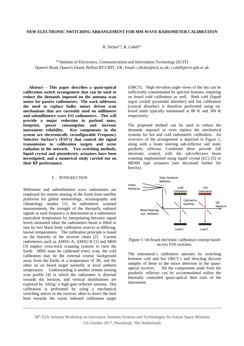
The proposed method can be used to reduce the
demands imposed or even replace the mechanical
systems for hot and cold radiometric calibration. An
overview of the arrangement is depicted in Figure 1,
along with a beam steering sub-reflector and static
parabolic reflector. Combined these provide full
electronic control, with the sub-reflectors beam
scanning implemented using liquid crystal (LC) [5] or
MEMS type actuators (not discussed further for
brevity).
Figure 1: On board electronic calibration concept based
on two FSS switches.
The instrument’s calibration operates by switching
between cold and hot OBCT’s and directing discrete
samples of these to the mixer detectors in the quasi-
optical receiver. All the components aside from the
parabolic reflector can be accommodated within the
thermally controlled quasi-optical feed train of the
instrument.

38th ESA Antenna Workshop on Innovative Antenna Systems and Technologies for Future Space Missions
3-6 October 2017, Noordwijk, The Netherlands
II. CALIBRATION SWITCHING METHOD
The quasi-optical calibration switch is obtained by
reconfiguring the spectral response of two bandpass
FSS filters, the method is shown in Figure 2. For hot
calibration both FSS are switched to reflection mode,
opening the hot target channel to the receiver in the QO
network. For cold calibration the first FSS in the
network is switched to reflection mode and second FSS
is switched to transmission mode, providing an open
channel from the cold target to the receiver. For scene
radiation capture, both FSS switches operate in
transmission providing an open channel from the
receiver to the scene, this configuration is shown in
Figure 1.
The FSS provides signal transmission with low insertion
loss when the bandpass spectral response is positioned
at the centre of the operating frequency band. For
switching off the signal the filters stopband response is
shifted into the operating frequency band. Providing a
signal band that can be dynamically reduced and
therefore high isolation is obtained.
(a)
(b)
Figure 2: Proposed electronic calibration switch
concept, (a) hot calibration (b) cold calibration.
In this paper two different methods for reconfiguring the
filter response are investigated. Both these have the
potential to provide low insertion loss, wide bandwidth
and high switching speed.
III. LIQUID CRYSTAL MATERIAL ACTUATED FSS
Electronic control of LC material provides a means to
reconfigure the bandpass filter response of the FSS, by
exploiting the dielectric anisotropy property of a thin
layer of nematic state LC material which is sandwiched
between the array as shown in Figure 3. In the unbiased
(0V) state, the LC molecules are orientated parallel to
the surface of the periodic arrays which are covered
with a thin layer of alignment polyimide. The torque
necessary to rotate the molecules perpendicular to the
electrodes is obtained by applying a voltage between the
biasing layers. The permittivity of the LC substrate
therefore varies between two values ε// (0V state) and ε
(biased state), with practically no current consumption.
The electrical path length in the substrate can therefore
be altered electronically by the dielectric anisotropy of
the liquid crystals which is defined as //eff
.
Figure 3: Sectional view of a LC based FSS cell with
liquid crystal interlayer and quartz cladding.
The design was carried out in CST Microwave Studio
[6] and involved cascading two FSS layers with a small
gap separating the screens, as shown in Figure 4 (a) and
(b). The numerical model uses permittivity and loss
tangent values obtained for commercially available LC
material. The device was modelled using two quartz
wafers (r = 3.78), and a thin layer of GT3-23001,
which is manufactured by Merck for microwave
applications. When fully biased the LC mixture
provides = 2.5, tan = 0.0143 and unbiased = 3.3,
tan = 0.0038.
(a) (b)
Figure 4: (a) FSS LC multilayer structure, (b) exposed
copper layers with slots. Dimensions of unit cell dx =
310, dy = 325, slot length l = 247, slot width w = 40,

38th ESA Antenna Workshop on Innovative Antenna Systems and Technologies for Future Space Missions
3-6 October 2017, Noordwijk, The Netherlands
quartz thickness qt = 98.5, liquid crystal thickness lct =
50 (µm).
Preliminary computations depicted in Figure 5, show
that an ‘on’ bandwidth of 3.7% with 0.6 - 1 dB insertion
loss obtained at 330 GHz, for = 2.5 tan = 0.0143.
Figure 5: Transmission performance of the FSS
operating at TM 45 incidence. Passband covers 323.6
– 335.8 GHz with losses 0.6 - 1 dB. Switchable 323.6 –
335.8 GHz stopband provides isolation > 12dB.
When the dielectric constant of the material is switched
to = 3.3 tan = 0.0038 the passband transmission
drops providing ‘off’ switching and transmission falls
by a minimum of 12 dB, effectively attenuating the
transmission through the FSS.
IV. PIEZOELECTRIC ACTUATED FSS
Using this approach, the bandpass response can be
controlled by the proximity of a thin layer of high
permittivity dielectric material and a periodic slot FSS.
The amplitude and phase of waves passing through or
reflecting off the dielectric and FSS surfaces are
determined by the electromagnetic interaction between
the layers. The FSS [7] comprises a freestanding
mesh of strongly shaped slot elements formed into a
thin 12.5 µm metal screen. The design lends itself to
this concept and is used to demonstrate device
operation, not ultimate performance. The actuation
method uses piezoelectrics to reconfigure the dielectric
layer, providing spatial translation in front of the FSS’s
metal surface. In operation this increases the air gap
between the two layers, and shifts the FSS transmission
resonance higher in frequency. Using a high
permittivity material such as silicon (εr 11.9) gives a
significant amount of frequency change when the layer
is translated within the range of the piezoelectric
actuator (0 - 20µm). As the dielectric layer moves away
from the FSS the resonant frequency returns to the
freestanding case. A sectional view of the actuation
method is shown in Figure 6. The silicon diaphragm
layer when translated by 6 - 16 µm from the mesh
surface produces a 26 GHz frequency shift of the
passband which is centred around 275 GHz, this is
depicted in Figure 7. It also shows that the arrangement
provides switching between ‘on’ and ‘off’ states with
0.3 - 0.65 dB insertion loss, and high isolation of over
15 dB between 270 – 280 GHz. The physical movement
between the two screens can be precisely controlled by
the piezoelectric actuators positioned at the edges of the
device, their location is shown in Figure 6.
Figure 6: Piezoelectric actuation method.
To improve the devices isolation performance a two-
layer structure was formed. The simulation model is
shown in Figure 8 along with transmission results for
TE 45 incidence. These demonstrate a 10 GHz
passband with slightly higher insertion loss 0.5 - 0.9 dB,
but significantly improved isolation > 35 dB over the
same frequency range.
Figure 7: (top) Reconfigurable FSS, (bottom plot)
Simulated spectral response modelled from 250 – 310
GHz, passband frequency from 270 - 280 GHz, 0.3 -
0.65 dB insertion loss, switching to a minimum of 15
dB isolation.

38th ESA Antenna Workshop on Innovative Antenna Systems and Technologies for Future Space Missions
3-6 October 2017, Noordwijk, The Netherlands
(a)
(b)
Figure 8: (a) Two-layer reconfigurable FSS model, (b)
transmission simulated spectral responses over the
frequency range 250 - 310 GHz. Passband/ Stopband
centred around 275 GHz, switching bandwidth 270 -
280 GHz, from ‘on’ 0.6 - 0.9 dB insertion loss, to ‘off’
minimum isolation over 37 dB.
V. CONCLUSIONS AND FUTURE WORK
The simulated spectral results demonstrate that both
actuation methods, LC and piezoelectric can be used to
implement an FSS based calibration switch. The
predictions made over the frequency range 250 – 400
GHz, demonstrate RF performance that would fit with
radiometer operation that prioritised reduced weight and
power consumption over low insertion loss. The LC
structures insertion loss was between 0.6 - 1 dB with
minimum channel isolation of 12 dB over a 10 GHz
bandwidth at 330 GHz. For the piezoelectric
operated single layer FSS at 275 GHz the results were
improved with 0.3 - 0.65 dB insertion loss and isolation
over 15 dB. When this was modelled as a two-layer
FSS a significant increase in isolation to over 37 dB was
achieved, with insertion loss in the 0.6 – 0.9 dB range.
These preliminary results are very encouraging, and the
next phase of the project will be to investigate the
MEMS piezoelectric FSS further through manufacture
and test of a single layer device to prove the concept.
VI. ACKNOWLEDGMENTS
This work is supported by The Centre for Earth
Observation Instrumentation (CEOI). http://ceoi.ac.uk/
VII. REFERENCES
[1] Martin, R.J., Martin, D.H., (1996) “Quasi-optical antennas for
radiometric remote sensing,” Electron. Comm. Eng. J., vol. 8,
pp. 37–48.
[2] Saunders, R., Hewison, T., Stringer, S., Atkinson, N., (1995) “The radiometric characterization of AMSU-B," IEEE
Transactions on Microwave Theory and Techniques, vol.43,
no.4, pp.760-771. [3] www.eumetsat.int/website/home/Satellites/
CurrentSatellites/Metop/MetopDesign/MHS/index.html
[4] Cahill, R., Hall, J. Martin, R. (1994) “Technologies for millimetre remote sensing antennas,” IEE/SEE Seminar Digest
on Spacecraft Antennas, pp.8/1-8/8.
[5] Perez-Palomino, G., Florencio, R., Encinar, J. A., Barba, M., Dickie, R., Cahill, R., Baine, P., Bain, M. & Boix, R. R, (2014)
'Accurate and Efficient Modelling to Calculate the Voltage
Dependence of Liquid Crystal Based Reflectarray Cells’, Proc. IEEE Transactions on Antennas and Propagation, 62, 5, p. 2659-
2668. [6] CST Microwave Studio, [Online]. Available:
https://www.cst.com/Products/CSTMWS
[7] Dickie, R., Cahill, R., Gamble, H.S., Fusco, V.F., Henry, M., Oldfield, M.L., Huggard, P., Howard, P.G., Grant, N., Munroe,
Y., and de Maagt, P., (2009) ‘Submillimetre Wave Frequency
Selective Surface with Polarisation Independent Spectral Responses’, Proc. IEEE Antennas and Propagation, 57, (7), pp.
1985 – 1994.
Layer 1
Layer 2
Actuation Gap 6 - 17µm