Embed Size (px)
Citation preview

Rod type
Auto switch mountableRod type/
In-line motor type
Guide rod typeGuide rod type/
In-line motor type
Rod type
Note) LEY63 is applicable only to the in-line motor type
Rod type/In-line motor type
Guide rod type
Guide rod type/In-line motor type
Size: 25, 32
Rod Type Series LEY Guide Rod Type Series LEYG
Rod Type Guide Rod Type
®
RoHS
NewNew
Dust/Drip proof (IP65) specification: -X5
TypeStep Motor (Servo/24 VDC) TServo Motor (24 VDC)
AC Servo Motor
Step data input typeSeries LECP6/LECA6
Programless typeSeries LECP1
Pulse input typeSeries LECPA
For absolute encoderPulse input typeSeries LECSBCC-Link direct input typeSeries LECSCSSCNET III typeSeries LECSS
For incremental encoderPulse input type/Positioning typeSeries LECSA
Step Motor (Servo/24 VDC) AC Servo Motor
Servo Motor (24 VDC)
Type Not applicable to UL.
Controller/Driver
Driver Not applicable to UL.
64 points positioning
14 points positioning
Long stroke:Max. 500 mm (LEY32, 40)
Lateral end load: 5 times more
Compatible with sliding bearing andball bushing bearing.Compatible with moment load andstopper (sliding bearing).Either positioning or pushing control can be selected.Possible to hold the actuator with the rod pushing to a workpiece, etc.
High output motor (100/200/400 W)Improved high speed transfer abilityHigh acceleration/deceleration compatible (5,000 mm/s2)Pulse input/CC-Link/SSCNET III typesWith internal absolute encoder(For LECSB/C/S)
Rod Type Series LEY
Guide Rod Type Series LEYG
Mounting variationsDirect mounting: 3 directions, Bracket mounting: 3 typesEither positioning or pushing control can be selected.Possible to hold the actuator with the rod pushing to a workpiece, etc.
Compared with rod type, size 25 and 100 stroke
Size: 16, 25, 32, 40
Size: 16, 25, 32, 40
Size: 25, 32, 63 Note) Size: 25, 32
Dust/Drip proof (IP65) specification: -X5
Electric Actuators
CAT.ES100-83D
Series LEY

Scraper
A7.
5
A7.
5
Series LEY
Control of intermediate positioning and pushing is possible.High precision with ball screws (Positioning repeatability: 0.02 mm)
Prevents foreign matter from entering.
Singleknuckle joint
Simplejoint
Double knuckle joint
For manual piston rod operationAdjustment operation possiblewhen power OFF
Standard cableRobotic cable (Flexible cable)
F l i t d ti
Manual override screw
S d d bl
Offering 2 types of actuator cables
Rod Type Series LEY /Size: 16, 25, 32, 40
Step motor (Servo/24 VDC)Ideal for transfer of high load at alow speed and pushing operationServo motor (24 VDC)Stable at high speed and silent operation
Prevents a workpiecefrom dropping. (Holding)
Right sideparallel type
Left sideparallel type
In-linemotor type
Top mounting type is the standard product.T ti t i th t d d d t
Motor mounting position selectable
P t f i tt
p
Scraper
Rod end brackets
Height dimension shortened by up to 49%In-line motor type
When “Motor option/Withmotor cover” is selected.
For LEY16DFor LEY16
A DimensionSize In-line motor Motor top mounting1625
32, 40
35.546.561
67.592118
(mm)
Motor top/parallel type
In line
Operating range OFFON
Red Green Red
Optimum operating range
2-color indication solid state auto switchAppropriate setting of themounting position can beperformed without mistakes.
Motor cover available(Option)
Non-magnetizing lock mechanism(Option)
Speed
Wor
k lo
ad
Step motor
Servo motor2 types of motors selectable
Red G
Optimum o
out mistakes.es
TypeStep Motor (Servo/24 VDC) TServo Motor (24 VDC)
Auto switch
Pages 18, 19 For checking the limit and intermediate signalApplicable to the D-M9 and D-M9 W (2-color indication)Groove for auto switch The auto switches should be ordered separately. Refer to pages 20 and 21 for details.
A green light
lights up at theoptimum operatingrange.
Features 1

Rod Type Series LEY /Size: 25, 32, 63
Rod type
Rod type/In-line motor type
Rod type/In-line motor type
Speed
Wor
k lo
ad Step motor
AC servo motor
Servo motor
High output motor (100/200/400 W)Improved high speed transfer abilityHigh acceleration/deceleration compatible (5,000 mm/s2)Pulse input/CC-Link direct input/SSCNET III typesWith internal absolute encoder Incremental encoder can also be selected.
Type
Electric ActuatorsTAC Servo Motor
Added large bore size 63!
Work load
High output motor: 400 w
Max. speed: 1,000 mm/s 500 stroke
Max. pushing force: 1,910 (N)
Dust/Drip proof specification (IP65)
Horizontal
Vertical
80 kg
72 kg
Features 2

When the cylinder is retracted (initial value), the non-rotating accuracy without a load or deflection of the guide rods will be below the values shown in the table.
Bore size (mm)
Sliding bearing
Ball bushing bearing
16
0.06
0.07
25
0.05
0.06
32 40
Compact integrated guide rodsLateral load resistance and high non-rotating accuracy
Direct Mounting
Head end Rod end
Body bottom
Bracket Mounting
Head flange Double clevis
Body bottom tapped: When “U” is selected
Application Examples
Lifter Delivery Rotation
Pushingoperation
Pressfitting
Stopper
Improved rigidityLateral end load: 5 times more Compared with rod type, size25 and 100 stroke
Non-rotating accuracy improved by using two guide rods
Guide Rod Type Series LEYG /Size: 16, 25, 32, 40
Sliding bearingSuitable for lateral load applications such as a stopper where shock is appliedBall bushing bearingSmooth operation suitable forpusher and lifter
Compatible with sliding bearing and ball bushing bearing
Motor top mounting type
In-line motor type
TypeStep Motor (Servo/24 VDC) TServo Motor (24 VDC)
Guide Rod Type Series LEYG /Size: 25, 32
Foot Rod flange
Mounting Variations
TypeTAC Servo Motor
Guide rod type
Guide rod type/In-line motor type
Series LEY
For use of auto switches for the guide rod type LEYG series, refer to page 117.
Features 3

Enclosure: IP65Max. stroke: 500 mm
For size 32
Lub-retainerRetains grease oil film.
ScraperMaterial: Nylon
Prevents dust and water droplets from entering between the cable and motor cover.
Motor top mounting type
In-line motor type
Motor top mounting type
In-line motor type
LEY-X5 (Refer to page 22.)
LEY-X5 (Refer to page 101.)
Electric Actuators
AC Servo Motor (100/200 W)
Type
Type
Type
Step Motor (Servo/24 VDC)
TServo Motor (24 VDC)
P t d t d t
Seal connector
Protects the motor.P t t th t
Aluminum cover
Reduces internal pressure fluctuation to prevent dust and water droplets from entering.
R d i t l
Vent hole
Groove for auto switch
Dust/Drip proof (IP65) specification
25, 32
Size
In-line motor type
LEY63D - P(Refer to page 96./Option)
AC Servo Motor (400 W) Type
63
Size
Water resistant type (Coolant)For checking the limit and intermediate signal Order the water resistant 2-color indicationsolid state auto switch separately. (Refer to page 27.)
Features 4

Example of setting the step data Example of checking the operation status
Easy Mode for Simple Setting
Step Axis 1Step No. 0
Posn 123.45 mm
Speed 100 mm/s
Monitor Axis 1
Step No. 1
Posn 12.34 mm
Speed 10 mm/s
Step Axis 1Step No. 1Posn 80.00 mmSpeed 100 mm/s
Step Axis 1Step No. 0Posn 50.00 mmSpeed 200 mm/s
1st screen 1st screen
2nd screen 2nd screen
It can be registered by “SET” after entering the values.
Operation statuscan be checked.
Simple Setting to Use Straight Away
Start testing
Move for theconstant rate
Step data setting
Move jog
<When a PC is used>Controller setting software
Step data setting, test operation, move jog and move for the constant rate can be set and operated on one screen.
Unit linking the LECP6/LECA6 series and Fieldbus networkTwo methods of operationStep data input: Operate using preset step data in the controller.Numerical data input: The actuator operates using values such as position and speed from the PLC.
Step Data Input Type Series LECP6/LECA6
Gateway Unit Series LEC-G
LECP6 LECA6
If you want to use it right away, select “Easy Mode.”
<When a TB (teaching box) is used>
Teaching box screen
Simple screen without scrolling promotes ease of setting and operating.Pick up an icon from the first screen to select a function.Set up the step data and check the monitor on the second screen.
Data can be set with position and speed. (Other conditions are already set.)
Step motor(Servo/24 VDC)
Servo motor(24 VDC)
Powersupply
Up to 12 controllersare connectable
PLC
Electric gripperSeries LEH
Electric slide tableSeries LES
Electric actuator/Rod typeSeries LEY
Electric actuator/Slider typeSeries LEF
Electric actuator/Rotary tableSeries LER
Electric actuator/Miniature typeSeries LEP
Electric actuator/Guide rod sliderSeries LEL
Compatible electric actuators
Applicable Fieldbus protocols
Max. number of connectable controllers
24 VDCfor gateway unit
Serialcommunication
RS485
Fieldbusnetwork
Gateway(GW) unit Compatible
controllersSeries LEC
Step motor controller (Servo/24 VDC)Series LECP6
Servo motorcontroller(24 VDC)Series LECA6
12 8 5 12
Setting of jogand speed of theconstant rate
Features 5

Normal Mode for Detailed Setting
Step data setting, parameter setting, monitor, teaching, etc., are indicated in different windows.
Step datasetup window
Parametersetup window
Monitoring windowTeaching window
Controller setting software<When a PC is used>
Main menu screen
Step datasetup screen Test screen
Monitoring screen
Select normal mode when detailed setting is required.
<When a TB (teaching box) is used>
Teaching box screen
Step data can be set in detail.Signals and terminal status can be monitored.
Parameters can be set.JOG and constant rate movement, return to origin, test operation and testing of forced output can be performed.
Multiple step data can be stored in the teaching box, and transferred to the controller.Continuous test operation by up to 5 step data.
Each function (step data setting, test, monitor, etc.) can be selected from the main menu.
ControllerActuator
The actuator and controller are provided as a set. (They can be ordered separately.)
Confirm that the combination of the controller and the actuator is correct.<Check the following before use.>
Check the actuator label for model number. This matches the controller. Check Parallel I/O configuration matches (NPN or PNP).
Step Axis 1Step No. 0 Movement MOD
Test DRV Axis 1Step No. 1Posn 123.45 mm Stop
Menu Axis 1Step dataParameter Test
Out mon Axis 1BUSY[ ]SVRE[ ] SETON[ ]
Features 6

No programmingProgramless Type Series LECP1
Pulse Input Type Series LECPA
Setting position numberSetting a registered number for the stop positionMaximum 14 points
Moving the actuator to a stop position using FORWARD and REVERSE buttons
Registering the stop position using SET button
1 Setting a stop position2 Registration3
Positionselectingswitch
FORWARDandREVERSEbuttons
Positionnumberdisplay SET button
Capable of setting up an electric actuator operation without using a PC or teaching box
Speed/Acceleration
16-level adjustment
Speedadjustment switches
Accelerationadjustment switches
LECP1
Step motor(Servo/24 VDC)
A driver that uses pulse signals to allow positioning at any position.The actuator can be controlled from the customers’ positioning unit.
Return-to-origin command signalEnables automatic return-to-origin action.
With force limit function (Pushing force/Gripping force operation available)Pushing force/Positioning operation possible by switching signals.
Touch panel
PLCpositioningunit
Pulse signal
Step motor driver (Pulse input type)Series LECPA
Electric actuatorSeries LE
Features 7

Series LECP6/LECA6/LECP1/LECPA
Function
Setting Items
Number of step data
Operation command (I/O signal)
Completion signal
Input from controller setting software (PC) Input from teaching box
Select using controller operationbuttons
Input from controller setting software (PC) Input from teaching box
Input the numerical value from controller setting software (PC) or teaching box
Input the numerical value Direct teaching JOG teaching
Direct teaching JOG teaching
No “position” setting requiredPosition and speed set by pulse signal
64 points
Step No. [IN ] input [DRIVE] input
[INP] output
14 points
Step No. [IN ] input only
[OUT ] output
Pulse signal
[INP] output
—
Item Step data input typeLECP6/LECA6
Programless typeLECP1
Pulse input type LECPA
Step data “position”setting
Step data and parameter setting
Movement MOD
Speed
Position
Acceleration/Deceleration
Pushing force
Trigger LV
Pushing speed
Moving force
Area output
In position
Stroke (+)
Stroke (−)
ORIG direction
ORIG speed
ORIG ACC
JOG
MOVE
Return to ORIG
Test drive
Forced output
DRV mon
In/Out mon
Status
ALM Log record
Save/Load
Language
Step datasetting(Excerpt)
Parametersetting(Excerpt)
Test
Monitor
ALM
File
Other
Selection of “absolute position” and “relative position”
Transfer speed
[Position]: Target position[Pushing]: Pushing start position
Acceleration/deceleration during movement
Rate of force during pushing operation
Target force during pushing operation
Speed during pushing operation
Force during positioning operation
Conditions for area output signal to turn ON
[Position]: Width to the target position[Pushing]: How much it moves during pushing
+ side limit of position
− side limit of position
Direction of the return to origin can be set.
Speed during return to origin position
Acceleration during return to origin position
ON/OFF of the output terminal can be tested.
Alarm currently being generated can be confirmed.
Alarm generated in the past can be confirmed.
Can be changed to Japanese or English.
Set at ABS/INC
Set in units of 1 mm/s
Set in units of 0.01 mm
Set in units of 1 mm/s2
Set in units of 1%
Set in units of 1%
Set in units of 1 mm/s
Set to 100%
Set in units of 0.01 mm
Set to 0.5 mm or more(Units: 0.01 mm)
Set in units of 0.01 mm
Set in units of 0.01 mm
Compatible
Set in units of 1 mm/s
Set in units of 1 mm/s2
Compatible
Compatible
Compatible
Compatible
Compatible
Compatible
Compatible
Compatible
Compatible
×
×
×
×
×
×
×
×
×
×
×
×
×
×
×
×
×
×
×
Fixed value (ABS)
Select from 16-level
Direct teachingJOG teaching
Select from 16-level
Select from 3-level (weak, medium, strong)
No setting required (same value as pushing force)
No setting required
Compatible
No setting required
Compatible
Compatible
Not compatible
Compatible (display alarm group)
Not compatible
Item ContentsStep datainput type
LECP6/LECA6
Easymode
TB PC
Normalmode
TB/PC
Programless typeLECP1
Continuous operation at the set speed can be tested while the switch is being pressed.Operation at the set distance and speed from the current position can be tested.
Continuous operation at the set speed can be tested while the switch is being pressed.Operation at the set distance and speed from the current position can be tested.
Current position, speed, force and the specified step data can be monitored.Current ON/OFF status of the input and output terminal can be monitored.
Step data and parameter can be saved, forwarded and deleted.
(Continuousoperation)
TB: Teaching box PC: Controller setting software
: Can be set from TB Ver. 2. (The version information is displayed on the initial screen) Programless type LECP1 cannot be used with the teaching box and controller setting kit.
No setting required
Set in units of 1%
Set in units of 1%
Set in units of 1 mm/s
Set to (Different values for each actuator)%
Set in units of 0.01 mm
Set to (Different values for each actuator) or more (Units: 0.01 mm)
Set in units of 0.01 mm
Set in units of 0.01 mm
Compatible
Set in units of 1 mm/s
Set in units of 1 mm/s
Compatible
Not compatible
Compatible
Compatible
Compatible
Compatible
Compatible
Compatible
Compatible
Pulse input typeLECPA
Operation of the specified step data
Hold down MANUAL button( ) for uniform sending(speed is specified value) Press MANUAL button ( ) once for sizing operation(speed, sizing amount are specified values)
Features 8

System Construction/General Purpose I/O
Series LEY
Electric actuator/Rod type
PLC
Controller
To CN4To CN3
To CN2
The mark: Can be included in the “How to Order” for the actuator.
Actuator cable
Teaching box(With 3 m cable)Part no.: LEC-T1-3JG
Power supply for I/O signal24 VDC Note)
Or
Option
To CN5
Pages 54, 68
Page 47
Page 58
LECP6/LECA6LECP1 (Programless)
Part no.LEC-CN5-LEC-CK4-
I/O cableController type
Pages 56, 69
LECP6 (Step data input type)LECA6 (Step data input type)LECP1 (Programless type)
LE-CP-LE-CA-LE-CP-
Robotic cableLE-CP- -S
—LE-CP- -S
Standard cableController type
USB cable
PC
Communication cable(3 m)
(A-miniB type)(0.3 m)
Controller setting kitController setting kit(Communication cable, conversion unit and USB cable are included.)Part no.: LEC-W2
Page 57
Touch Operator Interface (Provided by customer)GP4501T/GP3500TManufactured by Digital Electronics Corp.
Cockpit parts can be downloaded free via the Pro-face website. Using cockpit parts makes adjustment from the Touch Operator Interface possible.
Provided by customer
Page 63
Programless typeLECP1
To CN1
Power supply plug(Accessory)<Applicable cable size>AWG20 (0.5 mm2)
Power supply for controller24 VDC Note)
Step data input typeLECP6/LECA6
Note) When conformity to UL is required, the electric actuator and controller should be used with a UL1310 Class 2 power supply.
Provided by customer
Page 48
Note) Cannot be used with the programless type (LECP1).
Note) The teaching box, controller setting kit and Touch Operator Interface cannot be connected.
Features 9
System Construction/Pulse Signal
Electric Actuators
Electric actuator/Rod type
Driver
To CN4To CN3
To CN2
To CN1
The mark: Can be included in the “How to Order” for the actuator.
USB cable
PC
Communication cable
(A-miniB type)
Teaching box(With 3 m cable)Part no.: LEC-T1-3JG
Power supply plug (Accessory)<Applicable cable size>AWG20 (0.5 mm2)
Controller setting softwareCommunication cable (With conversion unit) and USB cable are included.Part no.: LEC-W2
Or
Option
To CN5
Page 70
Page 78 Page 77
LECPA (Pulse input type) LE-CP-Robotic cable
LE-CP- -SStandard cableDriver type
Actuator cable Page 75
Power supply for driver24 VDC Note)
Note) When conformity to UL is required, the electric actuator and driver should be used with a UL1310 Class 2 power supply.
Note) When conformity to UL is required, the electric actuator and driver should be used with a UL1310 Class 2 power supply.
PLC
Power supply for I/O signal24 VDC Note)
LECPAPart no.
LEC-CL5-
I/O cableDriver type
Page 76
Provided by customer
Provided by customer
Features 10

System Construction/Fieldbus Network
Series LEY
PC(Provided by customer)
Option
USB cable(A-miniB type)
Communicationcable
To CN4
Teaching box(With 3 m cable)Part no.: LEC-T1-3JG
Controller setting software(Communication cable and USB cable are included.)Part no.: LEC-W2
Series LEY
PLC(Provided by customer)
FieldbusnetworkPower
supply
Power supply forgateway unit24 VDC Note 1)
Terminating resistorconnector 120LEC-CGR
Communicationconnector(Accessory)
CC-Link Ver. 2.0DeviceNet™ only
Power supplyconnector(Accessory)
Gateway (GW) unit
Electric actuator/Rod type
To CN2
To CN3
To CN4
Power supplyconnector(Accessory) To CN1
To CN1Or
Controller inputpower supply Note 1)
Controller inputpower supply Note 1)
Communication cableLEC-CG1-
Branch connectorLEC-CGD
Controller Controller
Applicable Fieldbus protocolsCC-Link Ver. 2.0DeviceNet™PROFIBUS DPEtherNet/IP™
Cable between branchesLEC-CG2-
Power supplyconnector(Accessory)
To CN1
Communication cableLEC-CG1-
Compatible controllers
Applicable Fieldbus protocols
CC-Link Ver. 2.0
DeviceNet™
PROFIBUS DP
EtherNet/IP™
Max. number ofconnectable controllers
12
8
5
12
Step motor controller(Servo/24 VDC)
Servo motor controller(24 VDC)
Series LECP6
Series LECA6
Note 1) Connect the 0 V terminals for both the controller input power supply and gateway unit power supply.When conformity to UL is required, the electric actuator and controller should be used with a UL1310 Class 2 power supply.
Page 60
Page 60
Page 60
Page 57
Page 58
Page 60
Page 60
Page 48Page 48
Features 11

Electric Actuators
AC Servo Motor Driver Series LECS
Note 1) For positioning type, setting needs to be changed to use with maximum set values.Setup software (MR Configurator) LEC-MR-SETUP221 is required.
Note 2) Available when the Mitsubishi motion controller is used for the master equipment.
Positioning PulseNetwork
directinput
Control methodApplication/
FunctionCompatible motor
(100/200 VAC)
Series Setupsoftware
LEC-MR-SETUP221
Compatibleoption
100 W 200 W 400 W
LECSA(Pulse input type/Positioning type)
LECSB(Pulse input type)
LECSS (SSCNET III type)Compatible with Mitsubishi Electric’s servo system controller network
LECSC(CC-Link direct input type)
Up to7 points
Up to255 points
CC-LinkVer. 1.10
SSCNET III
Note 1)Synchronous
Note 2)
Series LECS list
Incr
emen
tal T
ype
Ab
solu
te T
ype
Features 12

Time
Settlingtime Settling
time
TimeS
peed
Spe
ed
Servo adjustment using auto gain tuning
With display setting function
Auto resonant filter function
Auto damping control function
(With the front cover opened)LECSALECSB
(With the front cover opened)
LECSS(With the front cover opened)
LECSC
Series LECS
Series LEY
AC Servo Motor Driver
Control the difference between command value and actual action
Automatically suppress low frequency machine vibrations (up to 100 Hz)
Features 13
One-touch servo adjustment
One-touch adjustment button
Display the monitor, parameter and alarm.
Display
Set parameters andmonitor display, etc.with push buttons.
Settings
Display
Control Baud rate, station number and the occupied station count.
Settings
Display the communication status with the driver, the alarm and the point table No.
Display the monitor, parameter and alarm.
Display
Set parameters andmonitor display, etc.with push buttons.
Settings
Display
Switches for selecting axis and switching to the test operation
Display the communication status with the driver and the alarm.
Settings

System Construction
Electric Actuators
Incremental encoder compatible Series LECSA
Driver
DriverAbsolute encoder compatible Series LECSB
Power supplyfor I/O signal
24 VDC
Power supplySingle phase 100 to 120 VAC (50/60 Hz) 200 to 230 VAC (50/60 Hz)
Provided by customer
Battery (Accessory)
Part no.: LEC-MR-RB-
PC
PC
Setup software(MR Configurator™)Part no.: LEC-MR-SETUP221
Part no.: (LEC-MR-J3BAT)
Provided by customer
Option
Option
Option
Provided bycustomer
Power supplySingle phase 100 to 120 VAC (50/60 Hz) 200 to 230 VAC (50/60 Hz)
Three phase 200 to 230 VAC (50/60 Hz)
Provided by customer
Control circuit power supply24 VDC
Option
Regeneration option
Standard cable Robotic cableLE-CSM-S LE-CSM-R
Motor cable
Motor cable
Page 131
Page 131
Page 131
Main circuit power supply connector(Accessory)
Page 125Page 132
Setup software(MR Configurator™)Part no.: LEC-MR-SETUP221
Page 132
Page 132
Page 131 Page 125
Page 131
I/O connectorPart no.: LE-CSNA
Option Page 131I/O connectorPart no.: LE-CSNB
USB cablePart no.: LEC-MR-J3USB
Page 132USB cablePart no.: LEC-MR-J3USB
Analogmonitor outputRS-422communication
Control circuit power supply connector(Accessory)
Page 126
Page 126
Control circuit power supply connector(Accessory)
Motor connector(Accessory)
Standard cable Robotic cableLE-CSB-S LE-CSB-R
Lock cable
Page 131
Page 131
Page 132
Lock cable
Standard cable Robotic cableLE-CSM-S LE-CSM-R
Standard cable Robotic cableLE-CSB-S LE-CSB-R
Standard cable Robotic cableLE-CSE-S LE-CSE-R
Encoder cable
Page 131Encoder cable
Provided by customer
PLC (Positioning unit)
Power supplyfor I/O signal
24 VDC
PLC (Positioning unit)
Standard cable Robotic cableLE-CSE-S LE-CSE-R
Order USB cable (Part no.: LEC-MR-J3USB) separately to use this software.
Order USB cable (Part no.: LEC-MR-J3USB) separately to use this software.
(Pulse input type/Positioning type)
(Pulse input type)
Electric actuator Rod type
Series LEYGuide rod type/In-line motor typeSeries LEYG
Part no.: LEC-MR-RB-
OptionRegeneration option
Page 131
Electric actuator Rod type
Series LEY
Pages 88, 110
Guide rod type/In-line motor typeSeries LEYG
Main circuit power supplyconnector(Accessory)
Page 126
Pages 88, 110
Features 14

System Construction
Driver
PC
Provided bycustomer
Power supplySingle phase 100 to 120 VAC (50/60 Hz) 200 to 230 VAC (50/60 Hz)
Three phase 200 to 230 VAC (50/60 Hz)
Provided by customer
Standard cable Robotic cableLE-CSM-S LE-CSM-R
Standard cable Robotic cableLE-CSB-S LE-CSB-R
Standard cable Robotic cableLE-CSE-S LE-CSE-R
PLC (CC-Link master unit)
CC-Link connector(Accessory)
Driver
Power supplySingle phase 100 to 120 VAC (50/60 Hz) 200 to 230 VAC (50/60 Hz)
Three phase 200 to 230 VAC (50/60 Hz)
Provided by customer
Standard cable Robotic cableLE-CSM-S LE-CSM-R
Standard cable Robotic cableLE-CSB-S LE-CSB-R
Standard cable Robotic cableLE-CSE-S LE-CSE-R
PLC (Positioning unit/Motion controller)
SSCNET IIIoptical cablePart no.: LE-CSS-
CN1ACN1B
CN1A
Absolute encoder compatible Series LECSC(CC-Link direct input type)
Absolute encoder compatible Series LECSS(SSCNET III type)
Series LEY
Part no.: LEC-MR-RB-
OptionRegeneration option
Page 131
Part no.: LEC-MR-RB-
OptionRegeneration option
Page 131
Motor cable Page 131
Page 131Lock cable
Motor cable Page 131
Page 131Lock cable
Electric actuator Rod type
Series LEY
Pages 88, 110
Guide rod type/In-line motor typeSeries LEYG
Page 131Encoder cable
Page 131Encoder cable
Main circuit power supplyconnector(Accessory)
Page 126
Main circuit power supplyconnector(Accessory)
Page 126
Page 126Control circuitpower supply connector(Accessory)
Page 126Motor connector(Accessory)
Battery (Accessory)Part no.: (LEC-MR-J3BAT)
Page 132
OptionPage 132USB cablePart no.: LEC-MR-J3USB
OptionPage 132USB cablePart no.: LEC-MR-J3USB
Setup software(MR Configurator™)Part no.: LEC-MR-SETUP221
Page 132
PC
Setup software(MR Configurator™)Part no.: LEC-MR-SETUP221
Page 132
Option Page 131I/O connectorPart no.: LE-CSNA
Power supplyfor I/O signal
24 VDC
RS-422communication
Electric actuator Rod type
Series LEY
Pages 88, 110
Guide rod type/In-line motor typeSeries LEYG
Page 126Control circuitpower supply connector(Accessory)
Page 126Motor connector(Accessory)
Battery (Accessory)Page 132
Part no.: (LEC-MR-J3BAT)
Option
Option Page 131
Page 131I/O connectorPart no.: LE-CSNS
Providedby
customer
Power supplyfor I/O signal
24 VDC
Features 15

High Rigidity Slider Type
Slider Type
Rod Type
SMC Electric Actuators
Guide rod typeSeries LEYG
Guide rod type /In-line motor typeSeries LEYG D
Size
16253240
Stroke(mm)
Up to 400Up to 600Up to 800Up to 1000
Max. work load(kg)
10204560
Series LEFS
253240
Up to 600Up to 800
Up to 1000
204560
Series LEFS
253240
Up to 2000Up to 2500Up to 3000
51525
Series LEFB
Ball screw driveSeries LEFS
Ball screw driveSeries LEFS
Belt driveSeries LEFB
Belt driveSeries LEFB
Basic type Series LEY
Basic typeSeries LEY
In-line motor typeSeries LEY D
Size
16253240
Stroke(mm)
Series LEY
Up to 300Up to 400Up to 500Up to 500
Pushing force(N)
1414527071058
16253240
Series LEYG
Up to 200Up to 300Up to 300Up to 300
141452707
1058
2532
Up to 400Up to 500
485588
Guide rod typeSeries LEYG
In-line motor typeSeries LEY D
Guide rod type/In-line motor typeSeries LEYG D
300
Series LEY
253263
Up to 400Up to 500Up to 800
4857361910
Series LEY
2532
485588
Series LEYG
3002532
485736
Series LEYG
Belt driveSeries LEJB
Ball screw driveSeries LEJS
162532
Up to 1000Up to 2000Up to 2000
15
14
Series LEFB
Size
4063
Stroke(mm)
200 to 1200300 to 1500
Max. workload (kg)
5585
Series LEJS
4063
200 to 2000300 to 3000
2030
Series LEJB
LEFB
Series LEFB
Guide Rod SliderBelt driveSeries LEL
25
Sliding bearingSeries LEL25M
3 Up to 1000 25
Ball bushing bearingSeries LEL25L
5 Up to 1000
Dust/Drip proof compatible
Clean room compatible Clean room compatible
Dust/Drip proof compatible
Dust/Drip proof compatible Dust/Drip proof compatible
SizeStroke(mm)
Pushing force(N)
SizeStroke(mm)
Pushing force(N)
SizeStroke(mm)
Pushing force(N)
SizeStroke(mm)
Pushing force(N)
AC Servo Motor
Step Motor (Servo/24 VDC) Servo Motor (24 VDC)
Step Motor (Servo/24 VDC) Servo Motor (24 VDC)
AC Servo Motor
AC Servo Motor
CAT.ES100-83
CAT.ES100-87
CAT.ES100-104
Step Motor (Servo/24 VDC)
CAT.ES100-101
SizeStroke(mm)
Max. work load(kg)
SizeStroke(mm)
Max. work load(kg)
SizeStroke(mm)
Max. work load(kg)
SizeStroke(mm)
Max. workload (kg)
SizeStroke(mm)
Max. workload (kg)
SizeStroke(mm)
Max. workload (kg)
SizeStroke(mm)
Pushing force(N)
Features 16
Rotary Table
Gripper
SMC Electric Actuators
Miniature
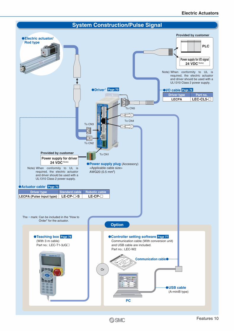
Step Motor (Servo/24 VDC) Servo Motor (24 VDC)Slide Table
610
Series LEPY
12
25, 50, 75610
Series LEPS
12
2550
High rigidity type Series LESH
2-finger typeSeries LEHZ
Rod typeSeries LEPY
Symmetrical type/L type Series LESH L
Basic type/R type Series LESH R
Basic type/R type Series LES R
2-finger type With dust coverSeries LEHZJ
In-line motor type/D type Series LESH D
Compact type Series LES
Symmetrical type/L type Series LES L
In-line motor type/D type Series LES D
2-finger type Long strokeSeries LEHF
3-finger typeSeries LEHS
Slide table typeSeries LEPS
Basic typeSeries LER
High precision typeSeries LERH
Note) ( ): Long stroke
816
25
26
9
50, 7550, 10050, 100
150
Size
8
16
25
Max. work load(kg)
1
3
5
Stroke(mm)
SizeMax. work load
(kg)Stroke(mm)
SizeMax. work load
(kg)Stroke(mm)
SizeMax. work load
(kg)Stroke(mm)
30, 50, 7530, 5075, 100
30, 50, 75100, 125, 150
Size
103050
Series LER
0.31.210
Rotating torque (N m)High torqueBasic
0.20.86.6
280
Max. speed ( /s)High torqueBasic
420
Size
101620253240
Series LEHZ
68
28
——
Max. gripping force (N)Basic Compact
4610142230
Stroke/bothsides (mm)
14
40
130210
Size
10162025
Series LEHZJ
68
28
Max. gripping force (N)Basic Compact
46
1014
Stroke/bothsides (mm)
14
40
Size
10203240
Series LEHF
728
120180
Max. grippingforce (N)
16 (32)24 (48)32 (64)40 (80)
Stroke/bothsides (mm)
Size
10203240
Series LEHS
3.517——
5.52290
130
Max. gripping force (N)Basic Compact
46812
Stroke/bothsides (mm)
CAT.ES100-77
CAT.ES100-94
Step Motor (Servo/24 VDC)
Step Motor (Servo/24 VDC)
CAT.ES100-92
Step Motor (Servo/24 VDC)
CAT.ES100-78
Features 17

Controller/Driver
Driver
Control motor
Servo motor(24 VDC)
Control motor
Step motor(Servo/24 VDC)
Step data input typeFor step motorSeries LECP6
Step data input typeFor servo motorSeries LECA6
Control motor
Step motor(Servo/24 VDC)
Programless typeSeries LECP1
Control motor
Step motor(Servo/24 VDC)
Pulse input typeSeries LECPA
Controller Driver
Fieldbus-compatible gateway (GW) unitSeries LEC-G
Gateway Unit
Control motor
AC servo motor(100/200/400 W)
Pulse input type/Positioning typeSeries LECSA(Incremental type)
Control motor
AC servo motor(100/200/400 W)
Pulse input typeSeries LECSB(Absolute type)
Control motor
AC servo motor(100/200/400 W)
CC-Link direct input typeSeries LECSC(Absolute type)
Control motor
AC servo motor(100/200/400 W)
SSCNET III typeSeries LECSS(Absolute type)
AC Servo Motor Driver
Applicable Fieldbus protocols
Max. number of connectable controllers 12 8 5 12
Features 18

Specifications
Step motor(Servo/24 VDC)
Electric Actuator Series LEY
Series
LEY25 S
LEY32 S
LEY63 S
LEY16
LEY25
LEY32
LEY40
LEY16 A
LEY25 A
Stroke(mm)
30 to 400
30 to 500
100 to 800
30 to 300
30 to 400
30 to 500
30 to 500
50 to 300
50 to 400
Pushingforce(N)
Verticalwork load
(kg)
131
255
485
157 (197)
308 (385)
588 (736)
521
1012
1910
38
74
141
122
238
452
189
370
707
283
553
1058
30
58
111
35
72
130
8
16
30
9 (12)
19 (24)
37 (46)
19
38
72
2
4
8
8
16
30
11
22
43
13
27
53
2
4
8
3
6
12
Speed(mm/s)
900
450
225
1200 (1000)
600 (500)
300 (250)
1000
500
250
15 to 500
8 to 250
4 to 125
18 to 500
9 to 250
5 to 125
24 to 500
12 to 250
6 to 125
24 to 300
12 to 150
6 to 75
15 to 500
8 to 250
4 to 125
18 to 500
9 to 250
5 to 125
Screwlead(mm)
12
6
3
20 (16)
10 (8)
5 (4)
20
10
5
10
5
2.5
12
6
3
16
8
4
16
8
4
10
5
2.5
12
6
3
Positioningrepeatability
(mm)
0.02or less
0.02or less
Referencepage
Page 2
SeriesLECP6
SeriesLECP1
SeriesLECPA
Servo motor(24 VDC)
AC servo motor
SeriesLECA6
Page 82
SeriesLECSASeriesLECSBSeriesLECSCSeriesLECSS
Controller/Driverseries
Specifications Series Stroke(mm)
Pushingforce(N)
Verticalwork load
(kg)
Speed(mm/s)
Screwlead(mm)
Positioningrepeatability
(mm)
Referencepage
Driverseries
Motor top/paralleltype
Motor top/paralleltype
In-line motortype
SRod Type
Referencepage
Page 47
LECP6
LECP1 LECPA
LECA6
Type
Step datainput type
Series
LECP6
LECA6
Compatiblemotor
Step motor(Servo/24 VDC)
Servo motor(24 VDC)
Powersupplyvoltage
24 VDC10%
Input
Parallel I/O
11 inputs(Photo-coupler
isolation)
Output
13 outputs(Photo-coupler
isolation)
Number ofpositioning
pattern points
64
Programlesstype LECP1 Step motor
(Servo/24 VDC)24 VDC
10%
6 inputs(Photo-coupler
isolation)
6 outputs(Photo-coupler
isolation)14
Pulse inputtype LECPA Step motor
(Servo/24 VDC)24 VDC
10%
5 inputs(Photo-coupler
isolation)
9 outputs(Photo-coupler
isolation)—
Controller/Driver LEC
The values shown in ( ): In-line motor type
Series
In-line motortype
Front matter 1

Variations
LECSC LECSS
0.02or less
Referencepage
Page 28
AC servo motor Page 106
SeriesLECSASeriesLECSBSeriesLECSCSeriesLECSS
Specifications
Step motor(Servo/24 VDC)
Electric Actuator Series LEYG
Series
LEYG16
LEYG25
LEYG32
LEYG40
Stroke(mm)
30 to 200
30 to 300
30 to 300
30 to 300
30 to 200
30 to 300
Pushingforce(N)
Verticalwork load
(kg)
38
74
141
122
238
452
189
370
707
283
553
1058
30
58
111
35
72
130
1.5
3.5
7.5
7
15
29
9
20
41
11
25
51
1.5
3.5
7.5
2
5
11
Speed(mm/s)
15 to 500
8 to 250
4 to 125
18 to 500
9 to 250
5 to 125
24 to 500
12 to 250
6 to 125
24 to 300
12 to 150
6 to 75
15 to 500
8 to 250
4 to 125
18 to 500
9 to 250
5 to 125
Screwlead(mm)
10
5
2.5
12
6
3
16
8
4
16
8
4
10
5
2.5
12
6
3
Controller/Driverseries
Specifications Series
LEYG25 S
LEYG32 S
Stroke(mm)
30 to 300
30 to 300
Pushingforce(N)
Verticalwork load
(kg)
131
255
485
157 (197)
308 (385)
588 (736)
7
15
29
7 (10)
17 (22)
35 (44)
Speed(mm/s)
900
450
225
1200 (1000)
600 (500)
300 (250)
Screwlead(mm)
12
6
3
20 (16)
10 (8)
5 (4)
Positioningrepeatability
(mm)
Referencepage
Driverseries
SeriesLECP6
SeriesLECP1
SeriesLECPA
Servo motor(24 VDC)
LEYG16 A
LEYG25 A
SeriesLECA6
Motor top mounting type
In-line motor type
Guide Rod Type
The values shown in ( ): In-line motor type
Guide rod type
Guide rod type/In-line motor type
Page 120LECSA LECSB
Pulse input type(For incremental
encoder)LECSA
6 inputs(Photo-coupler
isolation)
4 outputs(Photo-coupler
isolation)7
Pulse input type(For absolute
encoder)LECSB
AC servo motor(100/200/400 W)
100 to120 VAC
(50/60 Hz)200 to
230 VAC(50/60 Hz)
10 inputs(Photo-coupler
isolation)
6 outputs(Photo-coupler
isolation)—
CC-Link direct input type(For absolute
encoder)LECSC
4 inputs(Photo-coupler
isolation)
3 outputs(Photo-coupler
isolation)255
SSCNET III type(For absolute
encoder)LECSS
4 inputs(Photo-coupler
isolation)
3 outputs(Photo-coupler
isolation)—
ReferencepageType Series Compatible
motor
Powersupplyvoltage Input
Parallel I/O
Output
Number ofpositioning
pattern points
Driver LEC
Front matter 2

Step Motor (Servo/24 VDC)/Servo Motor (24 VDC) Type
Rod Type Series LEY
Rod Type Series LEY-X5
Model Selection Page 2How to Order Page 8Specifications Page 10Construction Page 12Dimensions Page 13Accessory Mounting Brackets Page 18
Auto Switch Page 20
Model Selection Page 6How to Order Page 22Specifications Page 23Construction Page 25Dimensions Page 26
Auto Switch Page 27
Guide Rod Type Series LEYGModel Selection Page 28How to Order Page 34Specifications Page 36Construction Page 38Dimensions Page 39Support Block Page 42
Specific Product Precautions Page 43
Guide Rod Type Series LEYG
Model Selection Page 106How to Order Page 110Specifications Page 112Construction Page 113Dimensions Page 114Support Block Page 116
Specific Product Precautions Page 117
Step Motor (Servo/24 VDC)/Servo Motor (24 VDC)
Controller/Driver
Step Data Input Type/Series LECP6/LECA6 Page 48Controller Setting Kit/LEC-W2 Page 57Teaching Box/LEC-T1 Page 58
Gateway Unit/Series LEC-G Page 60Programless Controller/Series LECP1 Page 63Step Motor Driver/Series LECPA Page 70
Controller Setting Kit/LEC-W2 Page 77Teaching Box/LEC-T1 Page 78
AC Servo Motor Type
Rod Type Series LEYModel Selection Page 82How to Order Page 88Specifications Page 90Construction Page 91Dimensions Page 92
Rod Type Series LEY-X5
Model Selection Page 82How to Order Page 101Specifications Page 102Construction Page 103Dimensions Page 104
Rod Type Series LEY
Model Selection Page 87How to Order Page 96Specifications Page 97Construction Page 98Dimensions Page 99
AC Servo Motor Driver/Series LECS Page 119
Specific Product Precautions Page 133
(Select options)
Dust/Drip proof (IP65) specification
25, 32Size
63Size
Dust/Drip proof (IP65) specificationDust/Drip proof (IP65) specification
Front matter 3

Step Motor (Servo/24 VDC) Servo Motor (24 VDC)
Page 2
P.28
Series LEYRod Type
Series LECP6/LECA6Series LEC-GSeries LECP1Series LECPA
Step Motor/Servo Motor ControllerStep Motor Driver
Series LEYGGuide Rod Type
In-line motor type
Motor top/parallel type
Motor top mounting type
In-line motor type
P.28pe
Motor top mounting type
In-line motor type
Dust/Drip proof (IP65) specification Page 22
Page 28
Page 47
Series LEY-X5
1
LE
YL
EC
SL
EC
A6
LE
CP
6L
EC
-GL
EC
P1
LE
CP
AL
EY
GL
EY
LE
YG
Mod
elS
elec
tion
Ser
vo M
otor
(24
VD
C)/S
tep
Mot
or (S
ervo
/24
VD
C)
AC
Ser
vo M
otor
Spec
ific P
rodu
ctPr
ecau
tions

T1
a1 a2
L
Spe
ed: V
[mm
/s]
Time [s]
T2 T3 T4
Wor
k lo
ad [k
g]
Speed [mm/s]
10
8
6
4
2
00 300200 400100 500 600
Step 1 Check the work load–speed. <Speed–Vertical work load graph>
Step 2 Check the cycle time.
Workpiece mass: 4 [kg] Speed: 100 [mm/s]
Acceleration/Deceleration: 3,000 [mm/s2]
Stroke: 200 [mm]
Workpiece mounting condition: Vertical upwarddownward transfer
Operatingconditions
Selection Procedure
Positioning Control Selection Procedure
Selection Example
Step 1Check the work load–speed.(Vertical transfer) Step 2 Check the cycle time.
Calculate the cycle time using the following calculation method.
Cycle time T can be found from the following equation.
Select the target model based on the workpiece mass and speed with reference to the <Speed–Vertical work load graph>.
Selection example) The LEY16B is temporarily selected based on the graph shown on the right side.
T = T1 + T2 + T3 + T4 [s]
T1 = V/a1 [s]
T4 = 0.2 [s]
T3 = V/a2 [s]
T2 = [s]L 0.5 V (T1 + T3)
V
T4: Settling time varies depending on the conditions such as motor types, load and in positioning of the step data. Therefore, please calculate the settling time with reference to the following value.
T2: Constant speed time can be found from the following equation.
T1: Acceleration time and T3: Deceleration time can be obtained by the following equation.
L : Stroke [mm] (Operating condition)V : Speed [mm/s] (Operating condition)a1: Acceleration [mm/s2] (Operating condition)a2: Deceleration [mm/s2] (Operating condition)
T1: Acceleration time [s] Time until reaching the set speedT2: Constant speed time [s] Time while the actuator is
operating at a constant speedT3: Deceleration time [s] Time from the beginning of the
constant speed operation to stopT4: Settling time [s] Time until in position is completedCalculation example)
T1 to T4 can be calculated as follows.
T1 = V/a1 = 100/3000 = 0.033 [s], T3 = V/a2 = 100/3000 = 0.033 [s]
T4 = 0.2 [s]
Therefore, the cycle time can be obtained as follows.T = T1 + T2 + T3 + T4 = 0.033 + 1.967 + 0.033 + 0.2 = 2.233 [s]
T2 = = = 1.97 [s]L 0.5 V (T1 + T3)
V
200 0.5 100 (0.033 + 0.033)
100
W
<Speed–Vertical work load graph>(LEY16/Step motor)
Lead 5: LEY16B
Lead 10: LEY16A
Lead 2.5: LEY16C
Based on the above calculation result, the LEY16B-200 is selected.
Electric Actuator/Rod Type
Series LEYModel Selection
Step Motor (Servo/24 VDC) Servo Motor (24 VDC)
2
It is necessary to mount a guide outside the actuator when used for horizontal transfer.When selecting the target model, refer to page 10 for the horizontal work load in the specifications, and page 43 for the precautions.

Duty ratio = A/B x 100 [%]
B
Pushing control
A
Pos
ition
Time
For
ce: F
[N]
Load
: F [N
]
Set value of pushing force [%] Note)
Note) Set values for the controller.
160
140
120
100
80
60
40
20
00 60%40% 80%20%
Stroke [mm]0 100 200 300 400 500 600
100%
100
10
1
<Graph of allowable lateral load on the rod end>
Step 1 Check the duty ratio.<Conversion table of pushing force–duty ratio>
Step 2 Check the pushing force. <Force conversion graph>
Mounting condition: Horizontal (pushing) Duty ratio: 20 [%]
Jig weight: 0.2 [kg] Speed: 100 [mm/s]
Pushing force: 60 [N] Stroke: 200 [mm]
Operatingconditions
Pushing Control Selection Procedure
Selection Example
Step 1 Check the duty ratio. Check the lateral load on the rod end.
Step 2 Check the pushing force.
Select the target model based on the set value of pushing force and force with reference to the <Force conversion graph>.
Selection example)Based on the graph shown on the right side,
Set value of pushing force: 70 [%]Pushing force: 60 [N]
Therefore, the LEY16B is temporarily selected.
Step 3 Check the lateral load on the rod end.<Graph of allowable lateral load on the rod end>Confirm the allowable lateral load on the rod end of the actuator:LEY16 , which has been selected temporarily with reference to the<Graph of allowable lateral load on the rod end>.
Selection example)Based on the graph shown on the right side,
Jig weight: 0.2 [kg] 2 [N]Product stroke: 200 [mm]
Therefore, the lateral load on the rod end is in the allowable range.
Select the [Pushing force] from the duty ratio with reference to the <Conversion table of pushing force–duty ratio>.
Selection example)Based on the table below,
Duty ratio: 20 [%]Therefore, the set value of pushing force will be 70 [%].
Step 3
The duty ratio is a ratio at the time that can keep being pushed.
Jig
[Set value of pushing force] is one of the step data input to the controller. [Continuous pushing time] is the time that the actuator can continuously keep pushing.
Set value ofpushing force [%]
40 or less
50
70
85
100
70
20
15
—
12
1.3
0.8
Duty ratio(%)
Continuouspushing time (minute)
<Force conversion graph>(LEY16/Step motor)
<Conversion table of pushing force–duty ratio>(LEY16/Step motor)
Max. 85%
Lead 2.5: LEY16C
Lead 5: LEY16B
Lead 10: LEY16A
LEY32
LEY25
LEY16
Based on the above calculation result, the LEY16B-200 is selected.
3
Model Selection Series LEY
LE
YL
EC
SSp
ecific
Pro
duct
Prec
autio
ns
AC
Ser
vo M
otor
LE
CA
6L
EC
P6
LE
C-G
LE
CP
1L
EC
PA
LE
YG
LE
YL
EY
GM
odel
Sel
ectio
n
Ser
vo M
otor
(24
VD
C)/S
tep
Mot
or (S
ervo
/24
VD
C)

Wor
k lo
ad [k
g]
Speed [mm/s]
35
30
25
20
15
10
5
00 300200 400100 500 600
Wor
k lo
ad [k
g]
Speed [mm/s]
50
40
30
20
10
00 300200 400100 500 600
Wor
k lo
ad [k
g]
Speed [mm/s]
60
50
40
30
20
10
00 300200100 400
Wor
k lo
ad [k
g]
Speed [mm/s]
14
12
10
8
6
4
2
00 300200 400100 500 600
Wor
k lo
ad [k
g]
Speed [mm/s]
10
8
6
4
2
00 300200 400100 500 600
Wor
k lo
ad [k
g]
Speed [mm/s]
10
8
6
4
2
00 300200 400100 500 600
Load
: F [N
]
Stroke [mm]
100
10
10 300200 400100 500 600
LEY32 /40
LEY16
LEY25
Lead 2.5: LEY16C
Lead 5: LEY16B
Lead 10: LEY16A
Lead 3: LEY25C
Lead 6: LEY25B
Lead 12: LEY25A
Lead 4: LEY32C
Lead 8: LEY32B
Lead 16: LEY32A
Lead 4: LEY40C
Lead 8: LEY40B
Lead 16: LEY40A
Lead 2.5: LEY16AC
Lead 5: LEY16AB
Lead 10: LEY16AA
Lead 3: LEY25AC
Lead 6: LEY25AB
Lead 12: LEY25AA
16
43
22
11
53
27
13
8
Step Motor (Servo/24 VDC) Servo Motor (24 VDC)
LEY16
LEY25
LEY32
LEY40
LEY25
LEY16
Graph of Allowable Lateral Load on the Rod End (Guide)
F
Center of gravity
[Stroke] = [Product stroke] +[Distance from the rod end to the center of gravity of the workpiece]
Workpiece
Speed–Vertical Work Load Graph (Guide)
4
Series LEY

For
ce [N
]F
orce
[N]
Set value of pushing force [%]
Set value of pushing force [%]
For
ce [N
]
Set value of pushing force [%]
For
ce [N
]
Set values for the controller.
Force Conversion Graph (Guide)
Non-rotating Accuracy of Rod
Step Motor (Servo/24 VDC)
LEY16
LEY25
LEY32
Set value of pushing force [%] Duty ratio [%] Continuous pushing time [minute]65 or less 100 —
Ambient temperature40 C or less
Ambient temperature Set value of pushing force [%] Duty ratio [%] Continuous pushing time [minute]85 or less40 or less
507085
25 C or less
40 C
100100702015
——121.30.8
Lead 2.5: LEY16CLead 5: LEY16B
Lead 10: LEY16A
Lead 3: LEY25C
Lead 6: LEY25BLead 12: LEY25A
Lead 4: LEY32CLead 8: LEY32B
Lead 16: LEY32A
020
40
60
80
100
120
140
160
10 20 30 40 50 60 70 80 90
10 20 30 40 50 60 70 80 90
10 20 30 40 50 60 70 80 90Set value of pushing force [%] Max. 85%
Max. 85%
0
100
200
300
400
500
Max. 65%
0100
200
300
400
500
600
700
800
LEY40
Set value of pushing force [%] Duty ratio [%] Continuous pushing time [minute]85 or less65 or less
85
10010050
——15
Ambient temperature25 C or less
40 C
Lead 4: LEY40CLead 8: LEY40B
Lead 16: LEY40A
10 20 30 40 50 60 70 80 900
100200300400500600700
1100
800900
1000
For
ce [N
]
Set value of pushing force [%]
Set value of pushing force [%]
For
ce [N
]
Max. 95%
Max. 95%
Servo Motor (24 VDC)
LEY16
LEY25
Set value of pushing force [%] Duty ratio [%] Continuous pushing time [minute]95 or less 100 —
Ambient temperature40 C or less
Set value of pushing force [%] Duty ratio [%] Continuous pushing time [minute]95 or less 100 —
Ambient temperature40 C or less
Model Pushing speed[mm/s]
Pushing force(Setting input value)
1 to 45 to 2021 to 50
1 to 45 to 2021 to 35
1 to 45 to 2021 to 30
1 to 45 to 2021 to 30
30% to 85%35% to 85%60% to 85%20% to 65%35% to 65%50% to 65%20% to 85%35% to 85%60% to 85%20% to 65%35% to 65%50% to 65%
LEY16
LEY25
LEY32
LEY40
<Pushing Force and Trigger Level Range> Without Load
Model Pushing speed[mm/s]
Pushing force(Setting input value)
1 to 45 to 2021 to 50
1 to 45 to 2021 to 35
40% to 95%60% to 95%80% to 95%40% to 95%60% to 95%80% to 95%
LEY16 A
LEY25 A
Note) For vertical loads (upward), set the pushing force to the maximum value shown below, and operate at the work load or less.
Model
LeadLEY16 LEY25 LEY32 LEY16 A LEY25 A
Work load [kg]Pushing force
1 1.585%
3A B C
2.5 565%
10A B C
4.5 985%
18A B C
LEY40
1465%
287A B C
1 1.595%
3A B C
1.2 2.595%
5A B C
Lead 2.5: LEY16AC
Lead 5: LEY16AB
Lead 10: LEY16AA
Lead 3: LEY25AC
Lead 6: LEY25AB
Lead 12: LEY25AA
0
20
40
60
80
100
120
20 30 40 50 60 70 80 90 100
20 30 40 50 60 70 80 90 1000
20
40
60
80
100
120
140
+
Size Non-rotating accuracy 16253240
1.10.8
0.7
Avoid using the electric actuator in such a way that rotational torque would be applied to the piston rod.This may cause deformation of the non-rotating guide, abnormal responses of the auto switch, play in the internal guide or an increase in the sliding resistance.
Max. 65%
5
Model Selection Series LEY
LE
YL
EC
SSp
ecific
Pro
duct
Prec
autio
ns
AC
Ser
vo M
otor
LE
CA
6L
EC
P6
LE
C-G
LE
CP
1L
EC
PA
LE
YG
LE
YL
EY
GM
odel
Sel
ectio
n
Ser
vo M
otor
(24
VD
C)/S
tep
Mot
or (S
ervo
/24
VD
C)

Load
: F [N
]
Stroke [mm]
100
10
10 300200 400100 500 600
LEY32
LEY25
Speed–Vertical Work Load Graph
Step Motor (Servo/24 VDC)
LEY25
LEY32
Servo Motor (24 VDC)
LEY25A
0
10
20
30
40
50
0 100 200 300 400 500 600
Speed [mm/s]
Wor
k lo
ad [k
g]
Lead 4: LEY32C
Lead 8: LEY32B
Lead 16: LEY32A
0
10
20
30
0 100 200 300 400 500 600
Speed [mm/s]
Wor
k lo
ad [k
g]
Lead 3: LEY25C
Lead 6: LEY25B
Lead 12: LEY25A
0
5
10
15
0 100 200 300 400 500 600
Speed [mm/s]
Wor
k lo
ad [k
g]
Lead 3: LEY25AC
Lead 6: LEY25AB
Lead 12: LEY25AA
Graph of Allowable Lateral Load on the Rod End (Guide)
F
Center of gravity
[Stroke] = [Product stroke] + [Distance from the rod end to the center of gravity of the workpiece]
Workpiece
Electric Actuator/Rod Type
Series LEY-X5Model Selection
Step Motor (Servo/24 VDC) Servo Motor (24 VDC)
Dust/Drip proof (IP65) specification
6
For
ce [N
]
Set value of pushing force [%]
Set value of pushing force [%]
For
ce [N
]
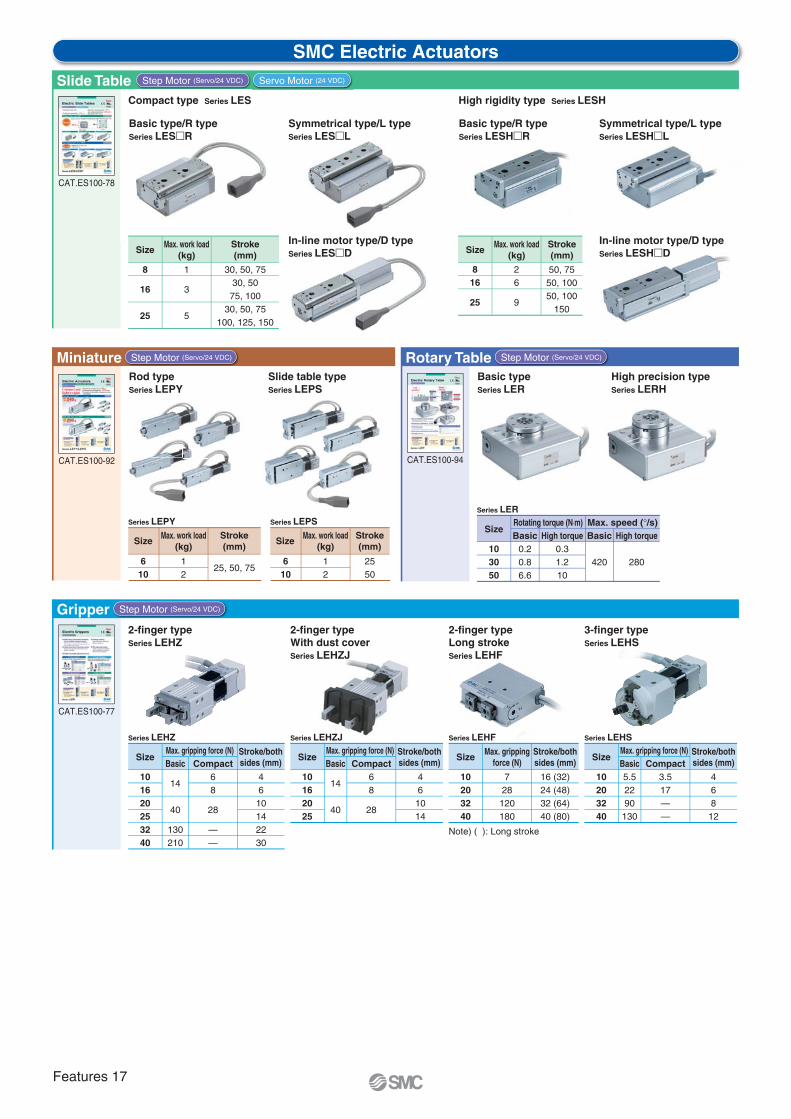
Force Conversion Graph
Step Motor (Servo/24 VDC) Servo Motor (24 VDC)
LEY25
LEY32
Set value of pushing force[%]
Duty ratio[%]
Continuous pushing time[minute]
65 or less 100 —
Ambient temperature
40 C or less
Set value of pushing force[%]
Duty ratio[%]
Continuous pushing time[minute]
85 or less65 or less
85
10010050
——15
Ambient temperature
25 C or less
40°C
Lead 3: LEY25C
Lead 6: LEY25B
Lead 12: LEY25A
Lead 4: LEY32C
Lead 8: LEY32B
Lead 16: LEY32A
10 20 30 40 50 60 70 80 90
10 20 30 40 50 60 70 80 90
Max. 85%
0
100
200
300
400
500
Max. 65%
0
100
200
300
400
500
600
700
800
Set value of pushing force [%]F
orce
[N]
Max. 95%
LEY25
Set value of pushing force[%]
Duty ratio[%]
Continuous pushing time[minute]
95 or less 100 —
Ambient temperature
40 C or less
Model Pushing speed[mm/s]
Pushing force(Setting input value)
1 to 4
5 to 20
21 to 35
1 to 4
5 to 20
21 to 30
20% to 65%
35% to 65%
50% to 65%
20% to 85%
35% to 85%
60% to 85%
LEY25
LEY32
<Pushing Force and Trigger Level Range> Without Load
Model Pushing speed[mm/s]
Pushing force(Setting input value)
1 to 4
5 to 20
21 to 35
40% to 95%
60% to 95%
80% to 95%
LEY25 A
Note) For vertical loads (upward), set the pushing force to the maximum value shown below, and operate at the work load or less.
Model
LeadLEY25 LEY32 LEY25 A
Work load [kg]Pushing force
2.5 565%
10A B C
4.5 985%
18A B C
1.2 2.595%
5A B C
Lead 3: LEY25AC
Lead 6: LEY25AB
Lead 12: LEY25AA
20 30 40 50 60 70 80 90 1000
20
40
60
80
100
120
140
Set values for the controller.
7
Model Selection Series LEY-X5Dust/Drip proof (IP65) specification
LE
YL
EC
SSp
ecific
Pro
duct
Prec
autio
ns
AC
Ser
vo M
otor
LE
CA
6L
EC
P6
LE
C-G
LE
CP
1L
EC
PA
LE
YG
LE
YL
EY
GM
odel
Sel
ectio
n
Ser
vo M
otor
(24
VD
C)/S
tep
Mot
or (S
ervo
/24
VD
C)

Confirm that the combination of the controller/driver and the actuator is correct.
The actuator and controller/driver are sold as a package.
<Check the following before use.> Check the actuator label for model number. This matches the controller/driver. Check Parallel I/O configuration matches (NPN or PNP)
How to Order
Electric Actuator/Rod Type
LEY16, 25, 32, 40Series LEY
LEY 16 30B 11 6N
16253240
NilRLD
Top mountingRight side parallelLeft side parallel
In-line
ABC
LEY16105
2.5
LEY251263
LEY32/401684
Symbol 30to
500 Refer to the applicable stroke table.
NilCB
Without optionWith motor cover
With lock 2
Nil
M
Rod end female thread
Rod end male thread(1 rod end nut is included.)
30to
500
1 When [With lock] is selected, [With motor cover] cannot be selected.
2 When “With lock” is selected for the top mounting and right/left side parallel types, the motor body will stick out of the end of the body for size 16 with strokes 30 or less. Check for interference with workpieces before selecting a model.
Refer to the operation manual for using the products. Please download it via our website, http://www.smcworld.com
Nil
A —
Symbol TypeSize
Step motor(Servo/24 VDC)
Servo motor(24 VDC)
Compatiblecontrollers/driver
LECP6LECP1LECPA
LECA6
LEY16 LEY25 LEY32/40
For auto switches, refer to pages 20 and 21.
S
Applicable stroke table
LEY16LEY25
LEY32/40
Stroke[mm]
Model30 50 100 150 200 250 300
—
350
—
400
——
450
——
500
10 to 30015 to 40020 to 500
Manufacturablestroke range [mm]
Consult with SMC for non-standard strokes as they are produced as special orders.
Size
Lead [mm] Stroke [mm]
Motor option 1 Rod end thread
Motor mounting position Motor type
[CE-compliant products]EMC compliance was tested by combining the electric actuator LEY series and the controller LEC series.The EMC depends on the configuration of the customer’s control panel and the relationship with other electrical equipment and wiring. Therefore conformity to the EMC directive cannot be certified for SMC components incorporated into the customer’s equipment under actual operating conditions. As a result it is necessary for the customer to verify conformity to the EMC directive for the machinery and equipment as a whole.For the servo motor (24 VDC)specification, EMC compliance was tested by installing a noise filter set (LEC-NFA). Refer to page 56 for the noise filter set.Refer to the LECA Operation Manual for installation.
[UL-compliant products]When conformity to UL is required, the electric actuator and controller/ driver should be used with a UL1310 Class 2 power supply.
Caution
®
RoHS
Step Motor (Servo/24 VDC) Servo Motor (24 VDC)
Standard
Motor
8

NilD
Screw mountingDIN rail mounting 1
Nil135
Without cable1.53 2
5 2
Nil6N6P1N1PANAP
Without controller/driver
Nil1358ABC
Without cable1.5358
101520
Produced upon receipt of order (Robotic cable only)Refer to the specifications Note 5) on page 10.
NilSR
Without cableStandard cable 2
Robotic cable (Flexible cable)NilULFGD
Ends tapped (Standard) 2
Body bottom tappedFoot
Rod flange 2
Head flange 2
Double clevis 3
Motor mounting positionTypeSymbol
Top/Parallel
4
In-line
—
——
1 Mounting bracket is shipped together, (but not assembled).
2 For horizontal cantilever mounting with the rod flange, head flange and ends tapped, use the actuator within the following stroke range.LEY25: 200 or lessLEY32/40: 100 or less
3 For mounting with the double clevis, use the actuator within the following stroke range.LEY16: 100 or lessLEY25: 200 or lessLEY32/40: 200 or less
4 Head flange is not available for the LEY32/40.
1 For details about controller/drivers and compatible motors, refer to the compatible controller/drivers below.
2 Only available for the motor type “Step motor.”
1 DIN rail is not included. Order it separately.
Mounting 1 Actuator cable type 1 Actuator cable length [m]
Controller/Driver type 1 I/O cable length [m] 1
Controller/Driver mounting
Compatible Controllers/Driver
Type
Series
Features
Compatible motor
LECP6 LECA6
24 VDC
Value (Step data) inputStandard controller
64 points
LECP1
Step motor(Servo/24 VDC)
Servo motor(24 VDC)
Step motor(Servo/24 VDC)
14 points
Capable of setting up operation (step data) withoutusing a PC or teaching box
Page 48 Page 48 Page 63
Step datainput type
Step datainput type
Programless type
LECPA
—
Operation by pulse signals
Page 70
Pulse input type
Maximum number of step data
Power supply voltage
Reference page
NPNPNPNPNPNPNPNPNP
LECP1 2
(Programless type)
LECPA 2
(Pulse input type)
LECP6/LECA6(Step data input type)
Motor mounting position: Top/Parallel
1 The standard cable should be used on fixed parts. For using on moving parts, select the robotic cable.
2 Only available for the motor type “Step motor.”
1 When “Without controllers/driver” is selected for controller/driver types, I/O cable cannot be selected. Refer to page 56 (For LECP6/ LECA6), page 69 (For LECP1) or page 76 (For LECPA) if I/O cable is required.
2 When “Pulse input type” is selected for controller/driver types, pulse input usable only with differential. Only 1.5 m cables usable with open collector.
on Top/Parallel Motor mounting position: In-line
9
Electric Actuator/Rod Type Series LEY
LE
YL
EC
SA
C S
ervo
Mot
orS
ervo
Mot
or (2
4 V
DC
)/Ste
p M
otor
(Ser
vo/2
4 V
DC
)L
EC
A6
LE
CP
6L
EC
-GL
EC
P1
LE
CP
AL
EY
GL
EY
LE
YG
Spec
ific P
rodu
ctPr
ecau
tions
Mod
elS
elec
tion
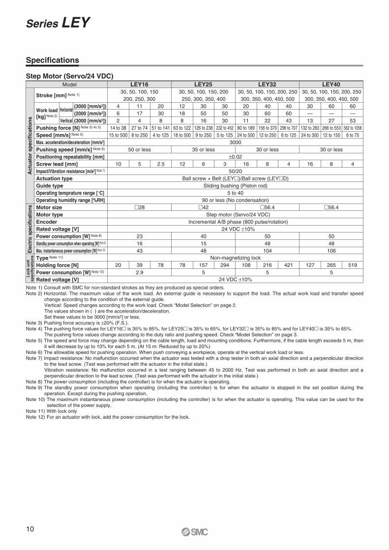
Note 1) Consult with SMC for non-standard strokes as they are produced as special orders.Note 2) Horizontal: The maximum value of the work load. An external guide is necessary to support the load. The actual work load and transfer speed
change according to the condition of the external guide.Vertical: Speed changes according to the work load. Check “Model Selection” on page 2.The values shown in ( ) are the acceleration/deceleration.Set these values to be 3000 [mm/s2] or less.
Note 3) Pushing force accuracy is 20% (F.S.).Note 4) The pushing force values for LEY16 is 35% to 85%, for LEY25 is 35% to 65%, for LEY32 is 35% to 85% and for LEY40 is 35% to 65%.
The pushing force values change according to the duty ratio and pushing speed. Check “Model Selection” on page 3.Note 5) The speed and force may change depending on the cable length, load and mounting conditions. Furthermore, if the cable length exceeds 5 m, then
it will decrease by up to 10% for each 5 m. (At 15 m: Reduced by up to 20%)Note 6) The allowable speed for pushing operation. When push conveying a workpiece, operate at the vertical work load or less.Note 7) Impact resistance: No malfunction occurred when the actuator was tested with a drop tester in both an axial direction and a perpendicular direction
to the lead screw. (Test was performed with the actuator in the initial state.)Vibration resistance: No malfunction occurred in a test ranging between 45 to 2000 Hz. Test was performed in both an axial direction and a perpendicular direction to the lead screw. (Test was performed with the actuator in the initial state.)
Note 8) The power consumption (including the controller) is for when the actuator is operating.Note 9) The standby power consumption when operating (including the controller) is for when the actuator is stopped in the set position during the
operation. Except during the pushing operation.Note 10) The maximum instantaneous power consumption (including the controller) is for when the actuator is operating. This value can be used for the
selection of the power supply.Note 11) With lock onlyNote 12) For an actuator with lock, add the power consumption for the lock.
Specifications
Model
462
14 to 3815 to 500
11174
27 to 748 to 250
50 or less 35 or less 30 or less 30 or less
20308
51 to 1414 to 125
12188
63 to 12218 to 500
305016
126 to 2389 to 250
305030
232 to 4525 to 125
203011
80 to 18924 to 500
406022
156 to 37012 to 250
406043
296 to 7076 to 125
30—13
132 to 28324 to 300
60—27
266 to 55312 to 150
60—53
562 to 10586 to 75
30, 50, 100, 150200, 250, 300
30, 50, 100, 150, 200250, 300, 350, 400
3000
0.02
50/20Ball screw + Belt (LEY )/Ball screw (LEY D)
Sliding bushing (Piston rod)5 to 40
90 or less (No condensation)
30, 50, 100, 150, 200, 250300, 350, 400, 450, 500
30, 50, 100, 150, 200, 250300, 350, 400, 450, 500
LEY16 LEY25 LEY32 LEY40
Stroke [mm] Note 1)
Pushing force [N] Note 3) 4) 5)
Speed [mm/s] Note 5)
Max. acceleration/deceleration [mm/s2]Pushing speed [mm/s] Note 6)
Positioning repeatability [mm]Screw lead [mm]Impact/Vibration resistance [m/s2] Note 7)
Actuation typeGuide typeOperating temprature range [ C]Operating humidity range [%RH]Motor sizeMotor typeEncoderRated voltage [V]Power consumption [W] Note 8)
Standby power consumption when operating [W] Note 9)
Max. instantaneous power consumption [W] Note 10)
Type Note 11)
Holding force [N]Power consumption [W] Note 12)
Rated voltage [V]
Work load[kg] Note 2)
Horizontal
Vertical
(3000 [mm/s2])(2000 [mm/s2])(3000 [mm/s2])
28 42Step motor (Servo/24 VDC)
Incremental A/B phase (800 pulse/rotation)24 VDC 10%
56.4 56.4
10 5 2.5 12 6 3 16 8 16 8 4
231643
401548
Non-magnetizing lock
24 VDC 10%
5048104
5048106
2.9 5 5
4
20 39 78 78 157 294 108 216 4215
127 265 519
Act
uat
or
spec
ific
atio
ns
Elec
tric
spe
cific
atio
nsL
ock
un
itsp
ecif
icat
ion
s
Step Motor (Servo/24 VDC)
10
Series LEY

Note 1) Consult with SMC for non-standard strokes as they are produced as special orders.
Note 2) Horizontal: The maximum value of the work load. An external guide is necessary to support the load. The actual work load and transfer speed change according to the condition of the external guide.Vertical: Check “Model Selection” on page 2 for details. The values shown in ( ) are the acceleration/deceleration.Set these values to be 3000 [mm/s2] or less.
Note 3) Pushing force accuracy is 20% (F.S.).Note 4) The pushing force values for LEY16A is 50% to 95% and for
LEY25A is 50% to 95%. The pushing force values change according to the duty ratio and pushing speed. Check “Model Selection” on page 3.
Note 5) The allowable speed for pushing operation. When push conveying a workpiece, operate at the vertical work load or less.
Note 6) Impact resistance: No malfunction occurred when the actuator was tested with a drop tester in both an axial direction and a perpendicular direction to the lead screw. (Test was performed with the actuator in the initial state.)Vibration resistance: No malfunction occurred in a test ranging between 45 to 2000 Hz. Test was performed in both an axial direction and a perpendicular direction to the lead screw. (Test was performed with the actuator in the initial state.)
Note 7) The power consumption (including the controller) is for when the actuator is operating.
Note 8) The standby power consumption when operating (including the controller) is for when the actuator is stopped in the set position during the operation. Except during the pushing operation.
Note 9) The maximum instantaneous power consumption (including the controller) is for when the actuator is operating. This value can be used for the selection of the power supply.
Note 10) With lock onlyNote 11) For an actuator with lock, add the power consumption for the
lock.
Specifications
Lo
ck u
nit
spec
ific
atio
ns
Model
3012
66 to 1305 to 125
156
37 to 729 to 250
35 or less
6
73
18 to 3518 to 500
128
57 to 1114 to 125
64
30 to 588 to 250
50 or less
32
16 to 3015 to 500
30, 50, 100, 150200, 250, 300
30, 50, 100, 150, 200250, 300, 350, 400
3000
0.02
50/20Ball screw + Belt (LEY )/Ball screw (LEY D)
Sliding bushing (Piston rod)5 to 40
90 or less (No condensation)
LEY16A LEY25A
Stroke [mm] Note 1)
Pushing force [N] Note 3) 4)
Speed [mm/s]Max. acceleration/deceleration [mm/s2]Pushing speed [mm/s] Note 5)
Positioning repeatability [mm]Screw lead [mm]Impact/Vibration resistance [m/s2] Note 6)
Actuation typeGuide typeOperating temperature range [ C]Operating humidity range [%RH]Motor sizeMotor output [W]Motor typeEncoderRated voltage [V]Power consumption [W] Note 7)
Standby power consumption when operating [W] Note 8)
Max. instantaneous power consumption [W] Note 9)
Type Note 10)
Holding force [N]Power consumption [W] Note 11)
Rated voltage [V]
2830
4236
404 (Horizontal)/6 (Vertical)
59
864 (Horizontal)/12 (Vertical)
96
Servo motor (24 VDC)Incremental A/B phase (800 pulse/rotation)/Z phase
24 VDC 10%
Non-magnetizing lock
24 VDC 10%2.9 5
3122.5510
157 29478783920
Act
uat
or
spec
ific
atio
ns
Ele
ctri
c sp
ecif
icat
ion
s
Servo Motor (24 VDC)
Work load[kg] Note 2)
HorizontalVertical
(3000 [mm/s2])(3000 [mm/s2])
Weight
Weight: Motor Top/Parallel TypeSeries
Step motorServo motor
LEY16 LEY25 LEY32Stroke [mm]
Additional WeightSize
LockMotor cover
Rod end male thread
Foot (2 sets including mounting bolt)Rod flange (including mounting bolt)Head flange (including mounting bolt)Double clevis (including pin, retaining ring and mounting bolt)
Male threadNut
Productweight [kg]
0.120.020.010.010.06
0.13
0.08
160.260.030.030.020.08
0.17
0.16
250.530.040.030.020.14
0.20
0.22
320.530.050.030.020.14
0.20
0.22
40[kg]
5004.89—
4004.32—
4504.60—
3003.74—
3504.03—
2003.17—
2503.46—
1002.49—
1502.77—
502.20—
302.09—
4002.562.52
3502.382.34
3002.212.17
2001.861.82
2502.031.99
1001.421.38
1501.681.64
501.251.21
301.181.14
3001.201.20
2000.980.98
2501.091.09
1000.730.73
1500.870.87
300.580.58
500.620.62
Series
Step motorServo motor
LEY40Stroke [mm]
Productweight [kg]
4504.90—
5005.19—
4004.62—
3504.33—
3004.04—
2003.47—
2503.76—
1002.79—
1503.07—
302.39—
502.50—
Series
Step motorServo motor
LEY40DStroke [mm]
Productweight [kg]
4504.89—
5005.18—
4004.61—
3504.32—
3004.03—
2003.46—
2503.75—
1002.78—
1503.06—
302.38—
502.49—
Weight: In-line Motor TypeSeries
Step motorServo motor
LEY16D LEY25D LEY32DStroke [mm]
Productweight [kg]
5004.88—
4004.31—
4504.59—
3003.73—
3504.02—
2003.16—
2503.45—
1002.48—
1502.76—
502.19—
302.08—
4002.552.51
3502.372.33
3002.202.16
2001.851.81
2502.021.98
1001.411.37
1501.671.63
501.241.20
301.171.13
3001.201.20
2000.980.98
2501.091.09
1000.730.73
1500.870.87
300.580.58
500.620.62
11
Electric Actuator/Rod Type Series LEY
LE
YL
EC
SA
C S
ervo
Mot
orS
ervo
Mot
or (2
4 V
DC
)/Ste
p M
otor
(Ser
vo/2
4 V
DC
)L
EC
A6
LE
CP
6L
EC
-GL
EC
P1
LE
CP
AL
EY
GL
EY
LE
YG
Spec
ific P
rodu
ctPr
ecau
tions
Mod
elS
elec
tion

In-line motor type: LEY D
16253240
Construction
No. Description Material Note1234567891011121314151617181920
BodyBall screw (shaft)Ball screw nutPistonPiston rodRod coverHousingRotation stopperSocketConnected shaftBushingBumperBearingReturn boxReturn plateMagnetWear ring holderWear ringScrew shaft pulleyMotor pulley
Aluminum alloyAlloy steel
Resin/Alloy steelAluminum alloyStainless steelAluminum alloyAluminum alloy
POMFree cutting carbon steelFree cutting carbon steelLead bronze cast
Urethane—
Aluminum die-castAluminum die-cast
—Stainless steel
POMAluminum alloyAluminum alloy
Anodized
Hard chrome anodized
Nickel platedNickel plated
Trivalent chromatedTrivalent chromated
Stroke 101 mm or moreStroke 101 mm or more
No. Size
211625
32, 40
Order no.LE-D-2-1LE-D-2-2LE-D-2-3
No. Description Material Note2122232425262728293031323334
BeltBearing stopperParallel pinSealRetaining ringMotorMotor coverGrommetMotor blockMotor adapterHubSpiderSocket (Male thread)Nut
—Aluminum alloyStainless steel
NBRSteel for spring
—Synthetic resinSynthetic resinAluminum alloyAluminum alloyAluminum alloy
NBRFree cutting carbon steel
Alloy steel
Phosphate coated
Only “With motor cover”Only “With motor cover”
AnodizedAnodized/LEY16, 25 only
Nickel plated
Replacement Parts (Top/Parallel only)/Belt
Component Parts
Motor top mounting type: LEY
16253240
When rod end male thread selected
12
Series LEY

A + Stroke
B + StrokeL
Y
XW
EH
EV
J
M
M
V
K Note 4)
H thread depth C
4 x O1 thread depth R
S
UT
M
M
4 x O1 thread depth R
Motor cable (2 x ø5)
T2
US
1
US
1
T2
65
Cab
le le
ngth
3
00
20
20 24
24
Step motor Servo motor
Connector
øD
2[2]
Origin Note 2)
[Stroke end]
Stroke end[Origin] Note 3)
Rod operating range Note 1)
Stroke
Dimensions: Motor Top/Parallel
Motor left side parallel type: LEY L16253240
Motor right side parallel type: LEY R16253240
Strokerange (mm)
10 to 100
101 to 300
15 to 100
101 to 400
20 to 100
101 to 500
20 to 100
101 to 500
101
121
130.5
155.5
148.5
178.5
148.5
178.5
90.5
110.5
116
141
130
160
130
160
10
13
13
13
Size
[mm]
16
25
32
40
A B C
16
20
25
25
D
34
44
51
51
EH
34.3
45.5
56.5
56.5
EV
M5 x 0.8
M8 x 1.25
M8 x 1.25
M8 x 1.25
H
18
24
31
31
J
14
17
22
22
K
10.5
14.5
18.5
18.5
L
25.5
34
40
40
M O1
7
8
10
10
R
35
46
60
60
S
67.5
92
118
118
T
0.5
1
1
1
U
28
42
56.4
56.4
V
61.8
63.4
68.4
90.4
W
80.3
85.4
95.4
117.4
X
62.5
59.6
—
—
W
81
81.6
—
—
X
22.5
26.5
34
34
Y
M4 x 0.7
M5 x 0.8
M6 x 1.0
M6 x 1.0
35.5
47
61
67
91
117
Size
1625
32, 40
S1 T2
0.5
1
1
U
[mm]
Step motor Servo motor
Note) When the motor is mounted on the left or right side in parallel, the groove for auto switch on the side to which the motor is mounted is hidden.
Note 1) Range within which the rod can move when it returns to origin. Make sure a workpiece mounted on the rod does not interfere with the workpieces and facilities around the rod.
Note 2) Position after return to origin.Note 3) The number in brackets indicates when the direction of return to origin has changed.Note 4) The direction of rod end width across flats ( K) differs depending on the products.
13
Electric Actuator/Rod Type Series LEY
LE
YL
EC
SA
C S
ervo
Mot
orS
ervo
Mot
or (2
4 V
DC
)/Ste
p M
otor
(Ser
vo/2
4 V
DC
)L
EC
A6
LE
CP
6L
EC
-GL
EC
P1
LE
CP
AL
EY
GL
EY
LE
YG
Spec
ific P
rodu
ctPr
ecau
tions
Mod
elS
elec
tion

20
20 24
24
Step motor Servo motor
Connector
UJ
EVT M
K Note 4)
M
EH
B + StrokeL W
65
Cab
le le
ngth
3
00
V
Y 2
S
A + Stroke
øD
H thread depth C
4 x O1
thread depth R
Motor cable (2 x ø5)
2[2]Origin Note 2)
[Stroke end]
Stroke end[Origin] Note 3)
Rod operating range Note 1)
Stroke
Dimensions: In-line Motor
Strokerange (mm)
10 to 100
101 to 300
15 to 100
101 to 400
20 to 100
101 to 500
20 to 100
101 to 500
166.3
186.3
195.4
220.4
216.9
246.9
238.9
268.9
167
187
191.6
216.6
—
—
—
—
92
112
115.5
140.5
128
158
128
158
10
13
13
13
Size
[mm]
16
25
32
40
CB
16
20
25
25
D
34
44
51
51
EH
34.3
45.5
56.5
56.5
EV
M5 x 0.8
M8 x 1.25
M8 x 1.25
M8 x 1.25
H
18
24
31
31
J
14
17
22
22
K
10.5
14.5
18.5
18.5
L
25.5
34
40
40
M O1
7
8
10
10
R
35
45
60
60
S
35.5
46.5
61
61
T
0.5
1.5
1
1
U
M4 x 0.7
M5 x 0.8
M6 x 1
M6 x 1
Note 1) Range within which the rod can move when it returns to origin. Make sure a workpiece mounted on the rod does not interfere with the workpieces and facilities around the rod.
Note 2) Position after return to origin.Note 3) The number in brackets indicates when the direction of return to origin has changed.Note 4) The direction of rod end width across flats ( K) differs depending on the products.
A
Stepmotor
Servomotor
Strokerange (mm)
10 to 100
101 to 300
15 to 100
101 to 400
20 to 100
101 to 500
20 to 100
101 to 500
Size
16
25
32
40
28
42
56.4
56.4
V
61.8
63.4
68.4
90.4
W
62.5
59.6
—
—
24
26
32
32
YStepmotor
Servomotor
14
Series LEY

Motor cable(2 x ø5)
Lock cable (ø3.5)
65
Cab
le le
ngth
4
00
2 VBA
C1
L2
H1
MM
L1
Width across flats B1
WX
Motor cable(2 x ø5)
Lock cable(ø3.5)
65
Cab
le le
ngth
4
00
2020
15
20
20
15
24
24
Step motor
Lockcable
Motorcable
Servo motor
Connector
X2T
2
Motor cable (2 x ø5)
65
Cab
le le
ngth
2
50
20
20 24
24
Step motor Servo motor
Connector
2020
15
20
20
15
24
24
Step motor
Lockcable
Motorcable
Servo motorConnector
L
CV
X2
T2
A
End male thread: LEY - M16253240
ABC
With motor cover: LEY - C16253240
ABC
With lock: LEY - B16253240
ABC
7.5
7.5
7.5
7.5
83
88.5
98.5
120.5
Size
16253240
T2 X2
[mm]
Motor cover material: Synthetic resin
103.3
103.9
111.4
133.4
Size
16253240
W121.8
125.9
138.4
160.4
X104.0
100.1
—
—
W122.5
122.1
—
—
X
[mm]
Refer to page 18 for details about the rod end nut and mounting bracket.
Note) Refer to the “Handling” precautions on pages 44 and 45 when mounting end brackets such as knuckle joint or work pieces.
13
22
22
12
20.5
20.5
Size
1625
32, 40
B1 C1
5
8
8
H1
24.5
38
42.0
L1
14
23.5
23.5
L2
M8 x 1.25
M14 x 1.5
M14 x 1.5
MM
[mm]
Dimensions
Step motor Servo motor
Motor top/parallel type
In-line motor type
With motor cover: LEY D - C16253240
ABC
With lock: LEY D - B16253240
ABC
7.5
7.5
7.5
7.5
100st or less
101st or more, 200st or less
100st or less
101st or more, 400st or less
100st or less
101st or more, 500st or less
100st or less
101st or more, 500st or less
66.5
68.5
73.5
95.5
Size Stroke range A169
189
198.5
223.5
220
250
242
272
16
25
32
40
T2 X2
35
46
60
60
L
43
54.5
68.5
68.5
CV[mm]
100st or less
101st or more, 200st or less
100st or less
101st or more, 400st or less
100st or less
101st or more, 500st or less
100st or less
101st or more, 500st or less
Size Stroke rangeA VB
207.8
227.8
235.9
260.9
259.9
289.9
281.9
311.9
Step motor
208.5
228.5
232.1
257.1
—
—
—
—
—
—
Servo motor
16
25
32
40
103.3
103.9
111.4
133.4
Step motor
104
100.1
Servo motor
[mm]
The L1 measurement is when the unit is in the original position. At this position, 2 mm at the end.
15
Electric Actuator/Rod Type Series LEY
LE
YL
EC
SA
C S
ervo
Mot
orS
ervo
Mot
or (2
4 V
DC
)/Ste
p M
otor
(Ser
vo/2
4 V
DC
)L
EC
A6
LE
CP
6L
EC
-GL
EC
P1
LE
CP
AL
EY
GL
EY
LE
YG
Spec
ific P
rodu
ctPr
ecau
tions
Mod
elS
elec
tion

Y Y
LS + Stroke
A + Stroke
LTLL
LT
LG
X X
LH
LY
LX
LZ
Special cap bolt
4 x øLD
Section XX
6 x MO thread depth MR
øXA H9 depth XA
L MA
MC
ML + Stroke (MB)
MD
MH
Section XX details
XA H9
XB
XA
Outward mounting
X Y
LS + Stroke LS1
Section XX
øXA H9 depth XA
MD
MC
ML + StrokeMAL
6 x MO thread depth MR
MH
Dimensions
Motor top/parallel: LEY - U16253240
ABC
ABC
Material: Carbon steel (Chromate treated) The A measurement is when the unit is in the original position. At this position, 2 mm at the end.
Note) When the motor mounting is the right or left side parallel type, the head side foot should be mounted outwards.
Strokerange (mm)
10 to 100
101 to 300
15 to 100
101 to 400
20 to 100
101 to 500
Size
16
25
3240
2.3
2.6
3.2
LT
24
30
36
LH
48
57
76
LX
40.3
51.5
61.5
LY
62
71
90
LZ
9.2
11.2
11.2
X
5.8
5.8
7
Y
Included parts Foot Body mounting bolt
[mm]
Strokerange (mm)
10 to 100
101 to 300
15 to 100
101 to 400
20 to 100
101 to 500
106.1
126.1
136.6
161.6
155.7
185.7
76.5
96.5
99
124
114
144
5.4
8.4
11.3
Size
3240
16
25
A LS LL
16.1
19.8
19.2
LS1
6.6
6.6
6.6
LD
2.8
3.5
4
LG
Foot
[mm]
Strokerange (mm)
10 to 39
40 to 100
101 to 300
15 to 39
40 to 100
101 to 124
125 to 200
201 to 400
20 to 39
40 to 100
101 to 124
125 to 200
201 to 500
23.5
31
46
32
41
49.5
58
36
43
51.5
60
15
20
25
10.5
14.5
18.5
Size
16
25
3240
L MA
35.5
46
55
MB
17
32
62
24
42
59
76
22
36
53
70
MC MD
23
29
30
MH
40
60
50
75
50
80
ML
Strokerange (mm)
10 to 39
40 to 100
101 to 300
15 to 39
40 to 100
101 to 124
125 to 200
201 to 400
20 to 39
40 to 100
101 to 124
125 to 200
201 to 500
4
5
6
M4 x 0.7
M5 x 0.8
M6 x 1
Size
16
25
3240
MO
5.5
6.5
8.5
MR
3
4
5
XA XB
Body Bottom Tapped
Foot: LEY - L16253240
In-line motor: LEY D - U
Body bottom tapped
Body bottom tapped 16253240
ABC
16
Series LEY
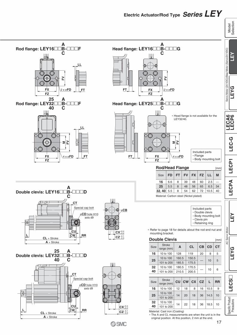
FZFX
M FV
FT 4 x øFDFZFX
FVM
FT
LL
4 x øFD
CURRCWL
CL + StrokeA + Stroke
CTSpecial cap bolt
øCD hole H10axis d9
+0.4+0.2CX0.10.3CZ
FXFZ
FV
FT
LL
2 x øFDFZFX
FV
FT 2 x øFD
A + StrokeCL + Stroke
CUCW RRL
CT
+0.4+0.2CX0.10.3CZ
øCBSpecial cap bolt
øCD hole H10axis d9
Rod flange: LEY16 - F Head flange: LEY16 - G
Rod flange: LEY - F
Double clevis: LEY16 - D
Double clevis: LEY - D253240
253240
ABC
ABC
ABC
ABC
ABC
ABC
Head flange: LEY25 - G
Strokerange (mm)
10 to 100
10 to 100
101 to 200
10 to 100
101 to 200
Size
3240
16
25
18
20
22
CW
12
14
14
CU
8
18
18
CX
16
36
36
CZ
10.5
14.5
18.5
L
9
10
10
RR
Material: Cast iron (Coating) The A and CL measurements are when the unit is in the original position. At this position, 2 mm at the end.
Included parts Double clevis Body mounting bolt Clevis pin Retaining ring
Included parts Flange Body mounting bolt
[mm]
Strokerange (mm)
10 to 100
10 to 100
101 to 200
10 to 100
101 to 200
128
160.5
185.5
180.5
210.5
119
150.5
175.5
170.5
200.5
20
—
—
Size
3240
16
25
A CL CB
8
10
10
CD
5
5
6
CT
Double Clevis
2.5
6.5
10.5
—
34
40
Size
1625
32, 40
LL
60
65
72
FZ
48
56
62
FX
39
48
54
FV
8
8
8
FT
6.6
5.5
5.5
FD M
[mm]
Material: Carbon steel (Nickel plated)
Rod/Head Flange
Refer to page 18 for details about the rod end nut and mounting bracket.
Head flange is not available for the LEY32/40.
17
Electric Actuator/Rod Type Series LEY
LE
YL
EC
SA
C S
ervo
Mot
orS
ervo
Mot
or (2
4 V
DC
)/Ste
p M
otor
(Ser
vo/2
4 V
DC
)L
EC
A6
LE
CP
6L
EC
-GL
EC
P1
LE
CP
AL
EY
GL
EY
LE
YG
Spec
ific P
rodu
ctPr
ecau
tions
Mod
elS
elec
tion

ø ø
ø ø
L2
L1
Accessory Brackets/Support Brackets
I-G02 I-G04 Y-G02 Y-G04
Knuckle Pin (Common with double clevis pin)
Mounting Brackets/Part No.
Rod End Nut
Single Knuckle Joint Double Knuckle Joint If a knuckle joint is used, select the body option [end male thread].
When ordering foot brackets, order 2 pieces per cylinder. Parts belonging to each bracket are as follows.Foot: Body mounting boltFlange: Body mounting boltDouble clevis: Clevis pin, Type C retaining ring for axis, Body mounting bolt
Knuckle pin and retaining ring are included.
10.3
12
11.5
14
Partno.
I-G02I-G04
Applicablesize
1625, 32, 40
R1
M8 x 1.25
M14 x 1.5
MM
25
30
L1
16
ø22
E1
8.5
14
A1
34
42
A U1
8
10
NDH10
8
18
NX
[mm]
+0.058 0
+0.058 0
0.20.4
0.30.5
10.3
12
Part no.
Y-G02Y-G04
Applicablesize
1625, 32, 40
R1
M8 x 1.25
M14 x 1.5
MM
25
30
L1
16
ø22
E1
8.5
16
A1
34
42
A
[mm]
Type C retaining ring 8
Type C retaining ring 10
Part no.
IY-G02IY-G04
Applicablesize
Retainingring
1625, 32, 40
7.6
9.6
d
1.5
1.55
m
0.9
1.15
t
16.2
36.2
L2
21
41.6
L1Dd9
8
10
[mm]
0.0400.076
0.0400.076
Material: Carbon steel
Part no.
NT-02NT-04
Applicablesize
1625, 32, 40
15.0
25.4
C
13
22
B
5
8
Hd
M8 x 1.25
M14 x 1.5
[mm]Material: Carbon steel (Nickel plated)
Applicablesize
1625
32, 40
Foot
LEY-L016
LEY-L025
LEY-L032
Flange
LEY-F016
LEY-F025
LEY-F032
Double clevis
LEY-D016
LEY-D025
LEY-D032
Material: Carbon steelSurface treatment: Nickel plated
Material: Cast ironSurface treatment: Nickel plated
Material: Carbon steelSurface treatment: Nickel plated
Material: Cast ironSurface treatment: Nickel plated
Series LEYAccessory Mounting Brackets
11.5
14
Part no.
Y-G02Y-G04
Applicablepin part no.
IY-G02IY-G04
Applicablesize
1625, 32, 40
16
36
NZ
21
41.6
LU1
8
10
NDH10
8
18
NX
+0.058 0
+0.058 0
+0.4+0.2
+0.5+0.3
øND hole H10axis d9
øND hole H10axis d9
18

T1U
VT2
FB
Joint
T1
T2V
B
Joint
Joint
Type A mounting bracket
Joint
Type B mounting bracket
HWith locking adhesive
C
L
ød
1
UT
UA
ød
2
K
M W
E
2 x øD
RS
M W
J
E2 x øO counterbore2 x øD through
Joint
Simple Joint Brackets The joint is not included in type A and type B mounting brackets. Therefore, it must be ordered separately.
Floating Joints (Refer to Best Pneumatics No. 2 for details.)
Type A Mounting Bracket
Material: Chromium molybdenum steel (Nickel plated)
Part no.
YA-03
Applicablesize
25, 32, 40 18
B
6.8
D
16
E
6
F
42
M
6.5
T1
10
T2
Part no.
YA-03
Applicablesize
25, 32, 40
6
U
18
V
56
W
55
Weight(g)
[mm]
Type B Mounting Bracket
Material: Stainless steel
Part no.
YB-03
Applicablesize
25, 32, 40 12
B
7
D
25
E
9
J
34
M
11.5 depth 7.5
øO
Part no.
YB-03
Applicablesize
25, 32, 40 6.5
T1
10
T2
18
V
50
W
9
RS
80
Weight(g)
[mm]
Material: Stainless steel
Part no.
LEY-U025
Applicablesize
25, 32, 40 17
UA
11
C
16
d1
8
d2
14
K
7
L
6
UT
22
Weight(g)
M8 x 1.25
H
[mm]
Joint and Mounting Bracket (Type A/B)/Part No.
LEY U025
025 25, 32, 40
Allowable Eccentricity [mm]
Applicable size
Eccentricity tolerance
Backlash
25 32 401
0.5
Joint and Mounting Bracket (Type A/B)/Part No.
Applicable size
25, 32, 40
Jointpart no.
LEY-U025
Applicable mounting bracket part no.
Type A mounting bracket
YA-03
Type B mounting bracket
YB-03
Applicable size
<How to Order> The joint is not included in type A and type B mounting brackets. Therefore, it must be ordered separately.
Example) Order no. Joint ......................................LEY-U025 Type A mounting bracket ......YA-03
For Male Thread/JA
For Male Thread/JS (Stainless steel)Stainless steel 304 (Appearance)
Dust coverFluororubber/Silicone rubber
For Male Thread/JC (Light weight type)With the aluminum case
For Female Thread/JB
BasicFoot
Flange
Applicable size
1625, 32, 40
Thread size
M5 x 0.8
M8 x 1.25
Applicable size
1625, 32, 40
Thread size
M8 x 1.25
M14 x 1.5
Joint
YA 03
Mounting bracketYAYB
Type A mounting bracket
Type B mounting bracket
03 25, 32, 40
Applicable size
Mountingbracket
19
Accessory Mounting Brackets Series LEY
LE
YL
EC
SA
C S
ervo
Mot
orS
ervo
Mot
or (2
4 V
DC
)/Ste
p M
otor
(Ser
vo/2
4 V
DC
)L
EC
A6
LE
CP
6L
EC
-GL
EC
P1
LE
CP
AL
EY
GL
EY
LE
YG
Spec
ific P
rodu
ctPr
ecau
tions
Mod
elS
elec
tion
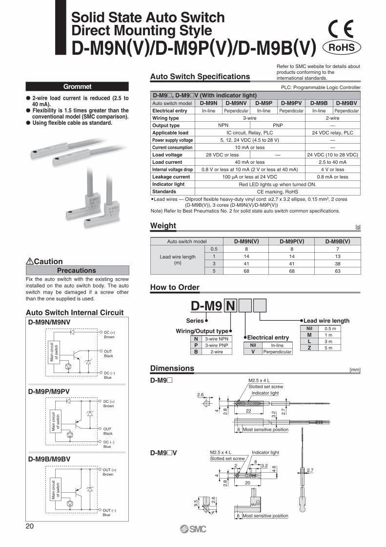
M2.5 x 4 LSlotted set screw
Indicator light
2.722
2.6
4
2.8
3.2
6 Most sensitive position
4
2.6
9.5
M2.5 x 4 LSlotted set screw
Indicator light
Most sensitive position
2
20
6
83.2
2.74.6
2.8
4
Mai
n ci
rcui
tof
sw
itch
Mai
n ci
rcui
tof
sw
itch
Mai
n ci
rcui
tof
sw
itch
DC (+)Brown
OUTBlack
DC ( )Blue
DC (+)Brown
OUTBlack
DC ( )Blue
Solid State Auto SwitchDirect Mounting StyleD-M9N(V)/D-M9P(V)/D-M9B(V)
Auto Switch Internal CircuitD-M9N/M9NV
D-M9B/M9BV
D-M9P/M9PV
Auto Switch Specifications
Weight
Auto switch model
0.5
1
3
5
D-M9N(V)8
14
41
68
D-M9P(V)8
14
41
68
D-M9B(V)7
13
38
63
[g]
Lead wire length(m)
Grommet PLC: Programmable Logic Controller
Auto switch model
Electrical entry
Wiring type
Output type
Applicable load
Power supply voltage
Current consumption
Load voltage
Load current
Internal voltage drop
Leakage current
Indicator light
Standards
D-M9NVD-M9N D-M9B D-M9BV
2-wire
—
24 VDC relay, PLC
—
—
24 VDC (10 to 28 VDC)
2.5 to 40 mA
4 V or less
0.8 mA or less
D-M9PVD-M9P
Red LED lights up when turned ON.
CE marking, RoHS
3-wire
IC circuit, Relay, PLC
5, 12, 24 VDC (4.5 to 28 V)
10 mA or less
40 mA or less
0.8 V or less at 10 mA (2 V or less at 40 mA)
100 μA or less at 24 VDC
In-line Perpendicular In-line Perpendicular In-line Perpendicular
NPN PNP
28 VDC or less —
OUT (+)Brown
OUT ( )Blue
D-M9 , D-M9 V (With indicator light)
Lead wires — Oilproof flexible heavy-duty vinyl cord: ø2.7 x 3.2 ellipse, 0.15 mm2, 2 cores (D-M9B(V)), 3 cores (D-M9N(V)/D-M9P(V))
Note) Refer to Best Pneumatics No. 2 for solid state auto switch common specifications.
How to Order
D-M9
D-M9 V
2-wire load current is reduced (2.5 to 40 mA).Flexibility is 1.5 times greater than the conventional model (SMC comparison).Using flexible cable as standard.
Refer to SMC website for details aboutproducts conforming to theinternational standards.
PrecautionsCaution
Dimensions [mm]
Fix the auto switch with the existing screw installed on the auto switch body. The auto switch may be damaged if a screw other than the one supplied is used.
Series
NPB
3-wire NPN3-wire PNP
2-wire
Wiring/Output type
D-M9 N
NilV
In-linePerpendicular
Electrical entry
NilMLZ
0.5 m1 m3 m5 m
Lead wire length
RoHS
20

M2.5 x 4 LSlotted set screw
Indicator light
2.722
2.6
4
2.8
3.2
6 Most sensitive position
4
2.6
9.5
M2.5 x 4 L
Slotted set screw
Indicator light
2.8
4.6
4
20
28
3.2
6 Most sensitive position
2.7
Auto Switch Specifications
Weight [g]
[mm]Dimensions
Auto switch model
0.5
1
3
5
D-M9NW(V)8
14
41
68
D-M9PW(V)8
14
41
68
D-M9BW(V)7
13
38
63
Lead wire length(m)
Grommet PLC: Programmable Logic Controller
Auto switch model
Electrical entry
Wiring type
Output type
Applicable load
Power supply voltage
Current consumption
Load voltage
Load current
Internal voltage drop
Leakage current
Indicator light
Standards
D-M9NWVD-M9NW D-M9BW D-M9BWV
2-wire
—
24 VDC relay, PLC
—
—
24 VDC (10 to 28 VDC)
2.5 to 40 mA
4 V or less
0.8 mA or less
D-M9PWVD-M9PW
Operating range Red LED lights up.Optimum operating range Green LED lights up.
3-wire
IC circuit, Relay, PLC
5, 12, 24 VDC (4.5 to 28 V)
10 mA or less
40 mA or less
0.8 V or less at 10 mA (2 V or less at 40 mA)
100 μA or less at 24 VDC
CE marking, RoHS
In-line Perpendicular In-line Perpendicular In-line Perpendicular
NPN PNP
28 VDC or less —
D-M9 W, D-M9 WV (With indicator light)
Lead wires — Oilproof flexible heavy-duty vinyl cord: ø2.7 x 3.2 ellipse, 0.15 mm2, 2 cores (D-M9BW(V)), 3 cores (D-M9NW(V), D-M9PW(V))
Note) Refer to Best Pneumatics No. 2 for solid state auto switch common specifications.
2-wire load current is reduced (2.5 to 40 mA).
Flexibility is 1.5 times greater than the conventional model (SMC comparison).
Using flexible cable as standard. The optimum operating range can be determined by the color of the light.(Red Green Red)
D-M9NW/M9NWV
D-M9BW/M9BWV
D-M9PW/M9PWV
OUTBlack
DC (+)Brown
DC ( )Blue
Mai
n ci
rcui
tof
sw
itch
DC (+)Brown
OUTBlack
DC ( )Blue
OUT (+)Brown
OUT ( )Blue
Auto Switch Internal Circuit
D-M9 W
D-M9 WV
Refer to SMC website for details aboutproducts conforming to theinternational standards.
2-Color Indication Solid State Auto SwitchDirect Mounting StyleD-M9NW(V)/D-M9PW(V)/D-M9BW(V)
PrecautionsCaution
Fix the auto switch with the existing screw installed on the auto switch body. The auto switch may be damaged if a screw other than the one supplied is used.
How to Order
Series
NPB
3-wire NPN3-wire PNP
2-wire
Wiring/Output type
D-M9 N W V L
NilV
In-linePerpendicular
Electrical entry
NilMLZ
0.5 m1 m3 m5 m
Lead wire length
Proper operating range
Operating range OFF
ON
RedDisplay
Green Red
Indicator light/Indication method
Mai
n ci
rcui
tof
sw
itch
Mai
n ci
rcui
tof
sw
itch
RoHS
21
LE
YL
EC
SA
C S
ervo
Mot
orS
ervo
Mot
or (2
4 V
DC
)/Ste
p M
otor
(Ser
vo/2
4 V
DC
)L
EC
A6
LE
CP
6L
EC
-GL
EC
P1
LE
CP
AL
EY
GL
EY
LE
YG
Spec
ific P
rodu
ctPr
ecau
tions
Mod
elS
elec
tion

Confirm that the combination of the controller/driver and the actuator is correct.
The actuator and controller/driver are sold as a package. (Controller/Driver Page 47)
<Check the following before use.> Check the actuator label for model number. This matches the controller/driver. Check Parallel I/O configuration matches (NPN or PNP).
Refer to the operation manual for using the products. Please download it via our website, http://www.smcworld.com
How to Order
R 6N 11D B25 50LEY X5Dust/Drop proofspecification
6N 1 X5X5
®
RoHS
2532
SizeNilD
Top mountingIn-line
Motor mounting position
ABC
LEY251263
LEY321684
Symbol Lead [mm]
Nil
A —
Symbol TypeCompatible
controllers/driverSize
Step motor(Servo/24 VDC)
LECP6LECP1LECPA
LECA6Servo motor
(24 VDC)
25 32
Motor type
30to
500
30to
500
Refer to the applicable stroke table.
Stroke [mm] Motor optionNilB
Without optionWith lock
Rod end threadNil
M
Rod end female threadRod end male thread
(1 rod end nut is included.)
I/O cable length [m] 1
Nil135
Without cable1.53 2
5 2
1358
ABC
1.5358
101520
Actuator cable length [m]
Cable is shipped assembled.R Robotic cable (Flexible cable)
Actuator cable type
1 Mounting bracket is shipped together, (but not assembled).
2 For horizontal cantilever mounting with the rod flange, head flange and ends tapped, use the actuator within the following stroke range.LEY25: 200 or less LEY32: 100 or less
3 Head flange is not available for the LEY32.
NilULFG
TypeMotor mounting position
Top mounting
3
In-line
—
—
Ends tapped (Standard) 2
Body bottom tappedFoot
Rod flange 2
Head flange 2
Symbol
Mounting 1
Controller/Driver mountingNilD
Screw mountingDIN rail mounting
DIN rail is not included. Order it separately.
Controller/Driver typeNil6N6P1N1PANAP
Without controller/driverNPNPNPNPNPNPNPNPNP
LECP6/LECA6(Step data input type)
LECP1(Programless type)
LECPA(Pulse input type)
Only available for the motor type “Step motor”.
[CE-compliant products]EMC compliance was tested by combining the electric actuator LEY series and the controller LEC series. The EMC depends on the configuration of the customer’s control panel and the relationship with other electrical equipment and wiring. Therefore conformity to the EMC directive cannot be certified for SMC components incorporated into the customer’s equipment under actual operating conditions. As a result it is necessary for the customer to verify conformity to the EMC directive for the machinery and equipment as a whole.For the servo motor (24 VDC) specification, EMC compliance was tested by installing a noise filter set (LEC-NFA). Refer to page 56 for the noise filter set. Refer to the LECA Operation Manual for installation.
[UL-compliant products]When conformity to UL is required, the electric actuator and controller/driver should be used with a UL1310 Class 2 power supply.
Caution
1 When “Without controller/driver” is selected for controller/driver types, I/O cable cannot be selected. Refer to page 56 (For LECP6/ LECA6), page 69 (For LECP1) or page 76 (For LECPA) if I/O cable is required.
2 When “Pulse input type” is selected for controller/driver types, pulse input usable only with differential. Only 1.5 m cables usable with open collector.
For auto switches, refer to page 27.
“-X5” is not added to an actuator model with a controller/driver part number suffix.
Example) “LEY25DB-100” for theLEY25DB-100BMU-P16NID-X5
Applicable stroke table
LEY25LEY32
30 50 100 150 200 250 300 350 400
—
450
—
500
Consult with SMC for non-standard strokes as they are produced as special orders.
Manufacturable stroke range[mm]
Standard
15 to 40020 to 500
StrokeModel
22
Electric Actuator/Rod Type
Size: 25, 32Series LEY-X5
Step Motor (Servo/24 VDC) Servo Motor (24 VDC)
Dust/Drip proof (IP65) specification

Specifications
Model LEY25 LEY32
12
18
7
63 to 122
18 to 400
12
78
30
50
15
126 to 238
9 to 200
35 or less
6
42
40
15
48
157
5
30, 50, 100, 150, 200250, 300, 350, 400
30, 50, 100, 150, 200250, 300, 350, 400, 450, 500
30
50
29
232 to 452
5 to 100
3
294
3,000
0.02
50/20
Sliding bushing (Piston rod)
IP65
5 to 40
90 or less (No condensation)
Step motor (Servo/24 VDC)
Incremental A/B phase (800 pulse/rotation)
24 VDC 10%
Non-magnetizing lock
24 VDC 10%
Ball screw + Belt (LEY )Ball screw (LEY D)
20
30
10
80 to 189
24 to 400
16
108
40
60
21
156 to 370
12 to 200
30 or less
8
56.4
50
48
104
216
5
40
60
42
296 to 707
6 to 100
4
421
Pushing force [N] Note 3) Note 4) Note 5)
Speed [mm/s] Note 5)
Max. acceleration/deceleration [mm/s2]
Pushing speed [mm/s] Note 6)
Positioning repeatability [mm]
Screw lead [mm]
Impact/Vibration resistance [m/s2] Note 7)
Actuation type
Guide type
Enclosure
Operating temprature range [ C]
Operating humidity range [%RH]
Motor size
Motor type
Encoder
Rated voltage [V]
Power consumption [W] Note 8)
Standby power consumption when operating [W] Note 9)
Max. instantaneous power consumption [W] Note 10)
Type Note 11)
Holding force [N]
Power consumption [W] Note 12)
Rated voltage [V]
Work load[kg] Note 2)
Stroke [mm] Note 1)
Horizontal
Vertical
(3000 [mm/s2])
(2000 [mm/s2])
(3000 [mm/s2])
Step Motor (Servo/24 VDC)
Act
uat
or
spec
ific
atio
ns
Ele
ctri
c sp
ecifi
catio
nsL
ock
un
itsp
ecif
icat
ion
s
Note 1) Consult with SMC for non-standard strokes as they are produced as special orders.Note 2) Horizontal: The maximum value of the work load. An external guide is necessary to support the load. The actual work load and transfer speed change
according to the condition of the external guide.Vertical: Speed changes according to the work load. Check “Model Selection” on page 6. The values shown in ( ) are the acceleration/deceleration. Set these values to be 3000 [mm/s2] or less.
Note 3) Pushing force accuracy is 20% (F.S.).Note 4) The pushing force values for LEY25 is 35% to 65% and for LEY32 is 35% to 85%. The pushing force values change according to the duty ratio
and pushing speed. Check “Model Selection” on page 7.Note 5) The speed and force may change depending on the cable length, load and mounting conditions. Furthermore, if the cable length exceeds 5 m, then
it will decrease by up to 10% for each 5 m. (At 15 m: Reduced by up to 20%)Note 6) The allowable speed for pushing operation. When push conveying a workpiece, operate at the vertical work load or less.Note 7) Impact resistance: No malfunction occurred when the actuator was tested with a drop tester in both an axial direction and a perpendicular direction
to the lead screw. (Test was performed with the actuator in the initial state.)Vibration resistance: No malfunction occurred in a test ranging between 45 to 2000 Hz. Test was performed in both an axial direction and a perpendicular direction to the lead screw. (Test was performed with the actuator in the initial state.)
Note 8) The power consumption (including the controller) is for when the actuator is operating.Note 9) The standby power consumption when operating (including the controller) is for when the actuator is stopped in the set position during the operation.
Except during the pushing operation.Note 10) The maximum instantaneous power consumption (including the controller) is for when the actuator is operating. This value can be used for the
selection of the power supply.Note 11) With lock onlyNote 12) For an actuator with lock, add the power consumption for the lock.
23
Electric Actuator/Rod Type Series LEY-X5Dust/Drip proof (IP65) specification
LE
YL
EC
SA
C S
ervo
Mot
orS
ervo
Mot
or (2
4 V
DC
)/Ste
p M
otor
(Ser
vo/2
4 V
DC
)L
EC
A6
LE
CP
6L
EC
-GL
EC
P1
LE
CP
AL
EY
GL
EY
LE
YG
Spec
ific P
rodu
ctPr
ecau
tions
Mod
elS
elec
tion

Specifications
Model LEY25A
7
2
18 to 35
18 to 400
12
78
15
5
37 to 72
9 to 200
3,000
35 or less
0.02
6
50/20
Sliding bushing (Piston rod)
IP65
5 to 40
90 or less (No condensation)
42
Servo motor (24 VDC)
Incremental A/B phase (800 pulse/rotation)/Z phase
24 VDC 10%
86
4 (Horizontal)/12 (Vertical)
96
Non-magnetizing lock
157
5
24 VDC 10%
30, 50, 100, 150, 200250, 300, 350, 400
30
11
66 to 130
5 to 100
3
294
Ball screw + Belt (LEY )Ball screw (LEY D)
Pushing force [N] Note 3) Note 4)
Speed [mm/s]
Max. acceleration/deceleration [mm/s2]
Pushing speed [mm/s] Note 5)
Positioning repeatability [mm]
Screw lead [mm]
Impact/Vibration resistance [m/s2] Note 6)
Actuation type
Guide type
Enclosure
Operating temprature range [ C]
Operating humidity range [%RH]
Motor size
Motor type
Encoder
Rated voltage [V]
Power consumption [W] Note 7)
Standby power consumption when operating [W] Note 8)
Max. instantaneous power consumption [W] Note 9)
Type Note 10)
Holding force [N]
Power consumption [W] Note 11)
Rated voltage [V]
Work load[kg] Note 2)
Stroke [mm] Note 1)
Horizontal
Vertical(3000 [mm/s2])
(3000 [mm/s2])
Servo Motor (24 VDC)
Act
uat
or
spec
ific
atio
ns
Ele
ctri
c sp
ecifi
catio
nsL
ock
un
itsp
ecif
icat
ion
s
Note 1) Consult with SMC for non-standard strokes as they are produced as special orders.
Note 2) Horizontal: The maximum value of the work load. An external guide is necessary to support the load. The actual work load and transfer speed change according to the condition of the external guide.Vertical: Speed changes according to the work load. Check “Model Selection” on page 6. The values shown in ( ) are the acceleration/deceleration.Set these values to be 3000 [mm/s2] or less.
Note 3) Pushing force accuracy is 20% (F.S.).Note 4) The pushing force values for LEY25A is 50% to
95%. The pushing force values change according to the duty ratio and pushing speed. Check “Model Selection” on page 7.
Note 5) The allowable speed for pushing operation. When push conveying a workpiece, operate at the vertical work load or less.
Note 6) Impact resistance: No malfunction occurred when the actuator was tested with a drop tester in both an axial direction and a perpendicular direction to the lead screw. (Test was performed with the actuator in the initial state.)Vibration resistance: No malfunction occurred in a test ranging between 45 to 2000 Hz. Test was performed in both an axial direction and a perpendicular direction to the lead screw. (Test was performed with the actuator in the initial state.)
Note 7) The power consumption (including the controller) is for when the actuator is operating.
Note 8) The standby power consumption when operating (including the controller) is for when the actuator is stopped in the set position during the operation with the maximum work load. Except during the pushing operation.
Note 9) The maximum instantaneous power consumption (including the controller) is for when the actuator is operating. This value can be used for the selection of the power supply.
Note 10) With lock onlyNote 11) For an actuator with lock, add the power
consumption for the lock.
Weight
Weight: Motor Top Mounting TypeModel LEY25 LEY32
30
1.45
1.41
50
1.52
1.48
100
1.69
1.65
150
1.95
1.91
200
2.13
2.09
250
2.30
2.26
300
2.48
2.44
350
2.65
2.61
400
2.83
2.79
30
2.48
—
50
2.59
—
100
2.88
—
150
3.35
—
200
3.64
—
250
3.91
—
300
4.21
—
350
4.49
—
400
4.76
—
450
5.04
—
500
5.32
—
Stroke [mm]
Productweight [kg]
Step motor
Servo motor
Productweight [kg]
Step motor
Servo motor
Weight: In-line Motor TypeModel LEY25D LEY32D
30
1.46
1.42
50
1.53
1.49
100
1.70
1.66
150
1.96
1.92
200
2.14
2.10
250
2.31
2.27
300
2.49
2.45
350
2.66
2.62
400
2.84
2.80
30
2.49
—
50
2.60
—
100
2.89
—
150
3.36
—
200
3.65
—
250
3.92
—
300
4.22
—
350
4.50
—
400
4.77
—
450
5.05
—
500
5.33
—
Stroke [mm]
Additional WeightSize
Lock
Rod end male thread
Foot (2 sets including mounting bolt)Rod flange (including mounting bolt)Head flange (including mounting bolt)
Male threadNut
0.330.030.020.08
0.17
250.630.030.020.14
0.20
32[kg]
24
Series LEY-X5Dust/Drip proof (IP65) specification

When rod end male thread selected
Construction
Motor top mounting type: LEY
Component PartsDescription Material Note
Aluminum alloy
Alloy steel
Resin/Alloy steel
Aluminum alloy
Stainless steel
Aluminum alloy
Aluminum alloy
POM
Free cutting carbon steel
Free cutting carbon steel
Lead bronze cast
Urethane
—
Aluminum die-cast
Aluminum die-cast
—
Stainless steel
POM
Aluminum alloy
Aluminum alloy
Anodized
Hard chrome anodized
Nickel plated
Nickel plated
Trivalent chromated
Trivalent chromated
Stroke 101 mm or more
Stroke 101 mm or more
Body
Ball screw (shaft)
Ball screw nut
Piston
Piston rod
Rod cover
Housing
Rotation stopper
Socket
Connected shaft
Bushing
Bumper
Bearing
Return box
Return plate
Magnet
Wear ring holder
Wear ring
Screw shaft pulley
Motor pulley
No.
1
2
3
4
5
6
7
8
9
10
11
12
13
14
15
16
17
18
19
20
—
Aluminum alloy
Stainless steel
Nylon
Steel for spring
—
Felt
NBR
NBR
Aluminum alloy
Aluminum alloy
—
Aluminum alloy
Aluminum alloy
NBR
Aluminum alloy
Aluminum alloy
Free cutting carbon steel
Alloy steel
Nickel plated
Anodized
Anodized
Anodized
Anodized
LEY25 only
Nickel plated
Belt
Bearing stopper
Parallel pin
Scraper
Retaining ring
Motor
Lub-retainer
O-ring
Gasket
Motor adapter
Motor cover
Seal connector
End cover
Hub
Spider
Motor block
Motor adapter
Socket (Male thread)
Nut
21
22
23
24
25
26
27
28
29
30
31
32
33
34
35
36
37
38
39
In-line motor type: LEY D
2532
2532
No. Size
212532
Order no.LE-D-2-2LE-D-2-3
Replacement Parts (Top mounting only)/BeltApplied portion Order no.
GR-S-010 (10 g)GR-S-020 (20 g)
Piston rod
Replacement Parts/Grease Pack
Apply grease on the piston rod periodically.Grease should be applied at 1 million cycles or 200 km, whichever comes sooner.
Description Material NoteNo.
25
Electric Actuator/Rod Type Series LEY-X5Dust/Drip proof (IP65) specification
LE
YL
EC
SA
C S
ervo
Mot
orS
ervo
Mot
or (2
4 V
DC
)/Ste
p M
otor
(Ser
vo/2
4 V
DC
)L
EC
A6
LE
CP
6L
EC
-GL
EC
P1
LE
CP
AL
EY
GL
EY
LE
YG
Spec
ific P
rodu
ctPr
ecau
tions
Mod
elS
elec
tion

T
M
SM
XW
Q
Y
A + Stroke
B + Stroke
Rod operating range Note 1)
Stroke
GV
OA
FV
EV
J
øOB
(GH)FHEHM
K Note 4)
M
øPB
PCL
øD
2
U
Actuator cable
H thread depth C
PA
[2]
Origin Note 2)
[Stroke end]Strokeend Note 3)
[Origin]
U
Q
A + Stroke
WB + Stroke
øP
B
YPA
Vent hole Note 5)
Applicable tubing O.D. ø4
Stroke
L
øD
øOB
FHEHM
M
GO
AF
VE
VJ
K Note 4)
H thread depth C[2] 2
Rod operating range Note 1)
Origin Note 2)
[Stroke end]Strokeend Note 3)
[Origin]
PC
Vent hole Note 5)
Applicable tubing O.D. ø4
4 x O1 thread depth R4 x O1 threaddepth R
4 x O1 thread depth R
Dimensions
Motor top mounting type
In-line motor type
Note 1) Range within which the rod can move when it returns to origin. Make sure a workpiece mounted on the rod does not interfere with the workpieces and facilities around the rod.Note 2) Position after return to origin.Note 3) The number in brackets indicates when the direction of return to origin has changed.Note 4) The direction of rod end width across flats ( K) differs depending on the products.Note 5) The vent hole is the port for releasing to atmosphere. Do not apply pressure to this hole.
Attach tubing to the vent hole and place the end of the tubing so it is not exposed to dust or water.
196
201
146
151
15.3
15.3
0.9
1
28
28
9.3
9.3
15.6
15.6
38
38
37
37
8
10
M5 x 0.8
M6 x 1.0
34
40
With lockWithout lockWPCUQ
24.5
26
YPBPAOBOARO1M
KJHGFVFHEVEHDCBA
15 to 100101 to 40020 to 100101 to 500
Strokerange (mm)
15 to 100101 to 40020 to 100101 to 500
Strokerange (mm)
Size
25
32
XWOARSize
25
32
OB PA PB Q S T U PCWith lockWithout lockWith lockWithout lock
Strokerange (mm)
15 to 100101 to 40020 to 100101 to 500
Strokerange (mm)
Size
25
32
Size
25
32
34
40
14.5
18.5
17
22
24
31
M8 x 1.25
M8 x 1.25
139.5
173.5
65.6
75.6
56.8
78.6
57.6
69.6
45.5
56.5
44
51
20
25
13
13
116141130160
130.5155.5148.5178.5
M
M5 x 0.8
M6 x 1.0
O1LKJHGVGHFVFHEVEHDCBA
1
1
Y
51
61
92
118
46
60
28
28
9.3
9.3
15.6
15.6
38
38
37
37
8
10
14.8
15.3
123
123
173
173
145
150
195
200
17
22
L
14.5
18.5
24
31
M8 x 1.25
M8 x 1.25
94.7
116.6
57.7
79.6
57.6
69.6
45.5
56.5
44
51
20
25
13
13
89.5124.596
126
With lock300 325 315.5345.5
Without lock250 275 265.5295.5
15 to 100101 to 40020 to 100101 to 500
For the rod end male thread, refer to page 15. For the mounting dimensions, refer to page 18.
26
Series LEY-X5Dust/Drip proof (IP65) specification

Optimum operating range
Operating range OFF
ON
RedDisplay
Green Red
Auto Switch Specifications
Weight [g]
Auto switch model
0.5
1
3
5
D-M9NA(V)8
14
41
68
D-M9PA(V)8
14
41
68
D-M9BA(V)7
13
38
63
Lead wire length(m)
PLC: Programmable Logic Controller
Auto switch model
Electrical entry
Wiring type
Output type
Applicable load
Power supply voltage
Current consumption
Load voltage
Load current
Internal voltage drop
Leakage current
Indicator light
Standards
D-M9NAVD-M9NA D-M9BA D-M9BAV
2-wire
—
24 VDC relay, PLC
—
—
24 VDC (10 to 28 VDC)
2.5 to 40 mA
4 V or less
0.8 mA or less
D-M9PAVD-M9PA
Operating range Red LED lights up.Optimum operating range Green LED lights up.
CE marking, RoHS
3-wire
IC circuit, Relay, PLC
5, 12, 24 VDC (4.5 to 28 V)
10 mA or less
40 mA or less
0.8 V or less at 10 mA (2 V or less at 40 mA)
100 μA or less at 24 VDC
In-line Perpendicular In-line Perpendicular In-line Perpendicular
NPN PNP
28 VDC or less —
D-M9 A, D-M9 AV (With indicator light)
Lead wires — Oilproof flexible heavy-duty vinyl cord: ø2.7 x 3.2 ellipse, 0.15 mm2, 2 cores (D-M9BA(V)), 3 cores (D-M9NA(V), D-M9PA(V))Note 1) Refer to Best Pneumatics No. 2 for solid state auto switch common specifications.Note 2) Refer to Best Pneumatics No. 2 for lead wire length.
2.7
6
2.6
9.3
Most sensitive position
4
SMC
22
3.2 4.6
2.8
4
28
M2.5 x 4 L Indicator light
4
0.2
3
SMC4
2.8
24 2.7
Indicator light
M2.5 x 4 L
Dimensions
D-M9 A
D-M9 AV
[mm]
6
3.2
Most sensitive position
Slotted set screw
Slotted set screw
Grommet
Water (coolant) resistant type 2-wire load current is reduced (2.5 to 40 mA). The optimum operating range can be determined by the color of the light. (Red Green Red) Using flexible cable as standard.
D-M9NA/M9NAV
D-M9BA/M9BAV
D-M9PA/M9PAV
OUTBlack
DC (+)Brown
DC ( )Blue
OUTBlack
DC (+)Brown
DC ( )Blue
OUT (+)Brown
OUT ( )Blue
Mai
n ci
rcui
tof
sw
itch
Indicator light/Indication method
Auto Switch Internal Circuit
Fix the auto switch with the existing screw installed on the auto switch body. The auto switch may be damaged if a screw other than the one supplied is used.
PrecautionsCaution
RoHS
Water Resistant 2-Color IndicationSolid State Auto Switch: Direct Mounting StyleD-M9NA(V)/D-M9PA(V)/D-M9BA(V)
Mai
n ci
rcui
tof
sw
itch
Mai
n ci
rcui
tof
sw
itch
27
LE
YL
EC
SA
C S
ervo
Mot
orS
ervo
Mot
or (2
4 V
DC
)/Ste
p M
otor
(Ser
vo/2
4 V
DC
)L
EC
A6
LE
CP
6L
EC
-GL
EC
P1
LE
CP
AL
EY
GL
EY
LE
YG
Spec
ific P
rodu
ctPr
ecau
tions
Mod
elS
elec
tion

Moment Load Graph
Selection conditions
Mounting position
Vertical Horizontal
Max. speed [mm/s]
Graph (Sliding bearing type)
Graph (Ball bushing bearing type)
“Speed–Vertical Work Load Graph”
,
,
Over 200
—
,
L L
m mL
m
L
m
200 or less
,
,
Electric Actuator/Guide Rod Type
Series LEYGModel Selection
For the sliding bearing type, the speed is restricted with a horizontal/moment load.
Vertical Mounting, Sliding Bearing 70 stroke or less Over 75 stroke
Vertical Mounting, Ball Bushing Bearing 35 stroke or less Over 40 stroke
The limit of vertical load mass varies depending on “lead” and “speed”. Check “Speed–Vertical Work Load Graph” on page 30.
The limit of vertical load mass varies depending on “lead” and “speed”.Check “Speed–Vertical Work Load Graph” on page 30.
Eccentric distance L [mm]
Load
mas
s m
[kg]
0.1
1
100
10
10 100 1000
LEYG32M /40M
LEYG25M
LEYG16M
LEYG16L
Eccentric distance L [mm]
Load
mas
s m
[kg]
0.1
1
100
10
10 100 1000
LEYG32M /40M
LEYG25MLEYG16M
Eccentric distance L [mm]
Load
mas
s m
[kg]
0.1
1
100
10
10 100 1000
LEYG32L /40L
LEYG25L
Eccentric distance L [mm]
Load
mas
s m
[kg]
0.1
1
100
10
10 100 1000
LEYG32L /40L
LEYG25L
LEYG16L
Step Motor (Servo/24 VDC) Servo Motor (24 VDC)
28

Transfer speed [m/min]
Wor
k lo
ad m
[kg]
504020 30105
100504030
20
10543
2
1
Stroke [mm]
Load
mas
s m
[kg]
Stroke [mm]
Load
mas
s m
[kg]
Stroke [mm]
Load
mas
s m
[kg]
Stroke [mm]
Load
mas
s m
[kg]
Stroke [mm]
Load
mas
s m
[kg]
Stroke [mm]
Load
mas
s m
[kg]
0.1
1
10
10 100 100035 400.1
1
10
10 100 100035 40
0.1
1
10
0.1
1
10
10 100 100035 40 10 100 100035 40
0.1
1
10
0.1
1
10
10 100 100070 75 10 100 100070 75
LEYG32M /40M
LEYG16M
LEYG25M
LEYG32M /40M
LEYG16M
LEYG25M
LEYG16M
LEYG25M
LEYG32M /40M
LEYG16M
LEYG25M
LEYG32M /40M
LEYG16LLEYG25L
LEYG32L /40L
LEYG16L
LEYG25L
LEYG32L /40L
LEYG16LLEYG25L
LEYG32L /40L
LEYG16L
LEYG25L
LEYG32L /40L
LEYG16L
LEYG25LLEYG32L /40L
LEYG16L
LEYG25LLEYG32L /40L
LEYG16L
LEYG25LLEYG32L /40L
LEYG16L
LEYG25L
LEYG32L /40L
120 125
120 125120 125
120 125
LEYG M (Sliding bearing)
L 5
0 m
m
m
Caution
Operating Range when Used as Stopper
Horizontal Mounting, Sliding Bearing L = 50 mm
Horizontal Mounting, Ball Bushing Bearing L = 50 mm Max. speed = 200 mm/s or less
Handling PrecautionsNote 1) When used as a stopper, select a
model with 30 stroke or less.Note 2) LEYG L (ball bushing bearing)
cannot be used as a stopper.Note 3) Workpiece collision in series with
guide rod cannot be permitted (Fig. a).Note 4) The body should not be mounted on
the end. It must be mounted on the top or bottom (Fig. b).
Set the speed to less than or equal to the values shown below.
For the specifications below, operate the system at the “load mass” shown in the graph x 80%. LEYG25MAA/Servo motor (24 VDC), Lead 12
Motor type LEYG M AStep motor (Servo/24 VDC)
Servo motor (24 VDC)200 mm/s200 mm/s
LEYG M B125 mm/s200 mm/s
LEYG M C75 mm/s
125 mm/s
L = 100 mm
L = 100 mm Max. speed = 200 mm/s or less
L = 50 mm Max. speed = Over 200 mm/s L = 100 mm Max. speed = Over 200 mm/s
LEYG32M/40M
LEYG25MLEYG16M
Moment Load Graph
Fig. a
Fig. b
m
29
Model Selection Series LEYG
LE
YL
EC
SSp
ecific
Pro
duct
Prec
autio
ns
AC
Ser
vo M
otor
LE
CA
6L
EC
P6
LE
C-G
LE
CP
1L
EC
PA
LE
YG
LE
YL
EY
GM
odel
Sel
ectio
n
Ser
vo M
otor
(24
VD
C)/S
tep
Mot
or (S
ervo
/24
VD
C)

6000 100 200 300 400 500
Speed [mm/s]
10
8
6
4
2
0
Wor
k lo
ad [k
g]
6000 100 200 300 400 500
Speed [mm/s]
30
20
10
0
Wor
k lo
ad [k
g]
6000 100 200 300 400 500
Speed [mm/s]
50
40
30
20
10
0
Wor
k lo
ad [k
g]
4000 100 200 300
Speed [mm/s]
60
50
40
30
20
10
0
Wor
k lo
ad [k
g]
6000 100 200 300 400 500
Speed [mm/s]
10
8
6
4
2
0
Wor
k lo
ad [k
g]
6000 100 200 300 400 500
Speed [mm/s]
15
10
5
0
Wor
k lo
ad [k
g]
Speed–Vertical Work Load Graph (Guide)
Step Motor (Servo/24 VDC)
LEYG16 ML
LEYG25 ML
Servo Motor (24 VDC)
LEYG16 AML
LEYG25 AML
LEYG32 ML
LEYG40 ML
Lead 2.5: LEYG16 CML
Lead 5: LEYG16 BML
Lead 10: LEYG16 AML
Lead 3: LEYG25 CML
Lead 6: LEYG25 BML
Lead 12: LEYG25 AML
Lead 4: LEYG32 CML
Lead 8: LEYG32 BML
Lead 16: LEYG32 AML
Lead 4: LEYG40 CML
Lead 8: LEYG40 BML
Lead 16: LEYG40 AML
Lead 2.5: LEYG16 ACML
Lead 5: LEYG16 ABML
Lead 10: LEYG16 AAML
Lead 3: LEYG25 ACML
Lead 6: LEYG25 ABML
Lead 12: LEYG25 AAML
30
Series LEYG

Set value of pushing force [%]
Pus
hing
forc
e [N
]
Set value of pushing force [%]
Pus
hing
forc
e [N
]
Set value of pushing force [%]
Pus
hing
forc
e [N
]
Set value of pushing force [%]
Pus
hing
forc
e [N
]
Set value of pushing force [%]
Pus
hing
forc
e [N
]
Max. 95%
Max. 95%
Set value of pushing force [%]
Pus
hing
forc
e [N
]
Force Conversion Graph (Guide)
Step Motor (Servo/24 VDC)
LEYG16 ML
LEYG25 ML
Servo Motor (24 VDC)
LEYG16 AML
LEYG25 AML
LEYG32 ML
Model Pushing speed[mm/s]
Pushing force(Setting input value)
1 to 4
5 to 20
21 to 50
1 to 4
5 to 20
21 to 35
1 to 4
5 to 20
21 to 30
1 to 4
5 to 20
21 to 30
30% to 85%
35% to 85%
60% to 85%
20% to 65%
35% to 65%
50% to 65%
20% to 85%
35% to 85%
60% to 85%
20% to 65%
35% to 65%
50% to 65%
LEYG16ML
LEYG25ML
LEYG32ML
LEYG40ML
<Pushing Force and Trigger Level Range> Without Load
Model Pushing speed[mm/s]
Pushing force(Setting input value)
1 to 4
5 to 20
21 to 50
1 to 4
5 to 20
21 to 35
40% to 95%
60% to 95%
80% to 95%
40% to 95%
60% to 95%
80% to 95%
LEYG16ML A
LEYG25ML A
Note) For vertical loads (upward), set the pushing force to the maximum value shown below, and operate at the work load or less.
Model
LeadLEYG16M
L LEYG25ML LEYG32M
L LEYG16ML A LEYG25M
L A
Work load [kg]Pushing force
0.5 185%
2.5A B C
1.5 465%
9A B C
2.5 785%
16A B C
LEYG40ML
5 1265%
26A B C
0.5 195%
2.5A B C
0.5 1.595%
4A B C
0
20
40
60
80
100
120
20 30 40 50 60 70 80 90 100
20 30 40 50 60 70 80 90 1000
20
40
60
80
100
120
140
020
40
60
80
100
120
140
160
10 20 30 40 50 60 70 80 90
10 20 30 40 50 60 70 80 90
10 20 30 40 50 60 70 80 90
Max. 85%
Max. 85%
0
100
200
300
400
500
Max. 65%
0100
200
300
400
500
600
700
800
LEYG40 ML
10 20 30 40 50 60 70 80 900
100200300400500600700
1100
800900
1000
Max. 65%
Lead 2.5: LEYG16 CML
Lead 5: LEYG16 BML
Lead 10: LEYG16 AML
Lead 3: LEYG25 CML
Lead 6: LEYG25 BML
Lead 12: LEYG25 AML
Lead 4: LEYG32 CML
Lead 8: LEYG32 BML
Lead 16: LEYG32 AML
Lead 4: LEYG40 CML
Lead 8: LEYG40 BML
Lead 16: LEYG40 AML
Lead 2.5: LEYG16 ACML
Lead 5: LEYG16 ABML
Lead 10: LEYG16 AAML
Lead 3: LEYG25 ACML
Lead 6: LEYG25 ABML
Lead 12: LEYG25 AAML
Set value of pushing force [%] Duty ratio [%] Continuous pushing time [minute]85 or less 100 —
Ambient temperature40 C or less
Set values for the controller.
31
Model Selection Series LEYG
LE
YL
EC
SSp
ecific
Pro
duct
Prec
autio
ns
AC
Ser
vo M
otor
LE
CA
6L
EC
P6
LE
C-G
LE
CP
1L
EC
PA
LE
YG
LE
YL
EY
GM
odel
Sel
ectio
n
Ser
vo M
otor
(24
VD
C)/S
tep
Mot
or (S
ervo
/24
VD
C)

Allowable Rotational Torque of Plate
Non-rotating Accuracy of Plate
Torque: T [N m]
+
Model30
0.70
0.82
1.56
1.52
2.55
2.80
2.55
2.80
LEYG16MLEYG16LLEYG25MLEYG25LLEYG32MLEYG32LLEYG40MLEYG40L
50
0.57
1.48
1.29
3.57
2.09
5.76
2.09
5.76
100
1.05
0.97
3.50
2.47
5.39
4.05
5.39
4.05
Stroke [mm]
200
0.56
0.57
2.18
2.05
3.26
3.23
3.26
3.23
300
—
—
1.36
1.44
1.88
2.32
1.88
2.32
T [N m]
SizeNon-rotating accuracy
16253240
LEYG M0.06
0.05
LEYG L0.07
0.06
32
Series LEYG

33
LE
YL
EC
SSp
ecific
Pro
duct
Prec
autio
ns
AC
Ser
vo M
otor
LE
CA
6L
EC
P6
LE
C-G
LE
CP
1L
EC
PA
LE
YG
LE
YL
EY
GM
odel
Sel
ectio
n
Ser
vo M
otor
(24
VD
C)/S
tep
Mot
or (S
ervo
/24
VD
C)

Confirm that the combination of the controller/driver and the actuator is correct.
The actuator and controller/driver are sold as a package.
<Check the following before use.> Check the actuator label for model number. This matches the controller/driver. Check Parallel I/O configuration matches (NPN or PNP).
How to Order
LEYG16, 25, 32, 40Series LEYG
LEYG 16 50B 11 6N
Refer to the operation manual for using the products. Please download it via our website, http://www.smcworld.com
M S
16253240
SizeML
Sliding bearingBall bushing bearing
When [M: Sliding bearing] is selected, the maximum speed of lead [A] is 400 mm/s (at no-load, horizontal mounting). The speed is also restricted with a horizontal/moment load. Refer to “Model Selection” on page 28.
Bearing type
NilD
Top mountingIn-line
Motor mounting position
ABC
LEYG16105
2.5
LEYG251263
LEYG32/401684
Symbol
Lead [mm]30to
300 Refer to the applicable stroke table.
30to
300
Stroke [mm]
Applicable stroke table
LEYG16LEYG25
LEYG32/40
Stroke[mm]
Model5030 100 150 200
—
250
—
300
10 to 20015 to 30020 to 300
Manufacturablestroke range [mm]
Consult with SMC for non-standard strokes as they are produced as special orders.
[CE-compliant products]EMC compliance was tested by combining the electric actuator LEYG series and the controller LEC series.The EMC depends on the configuration of the customer’s control panel and the relationship with other electrical equipment and wiring. Therefore conformity to the EMC directive cannot be certified for SMC components incorporated into the customer’s equipment under actual operating conditions. As a result it is necessary for the customer to verify conformity to the EMC directive for the machinery and equipment as a whole.For the servo motor (24 VDC) specification, EMC compliance was tested by installing a noise filter set (LEC-NFA). Refer to page 56 for the noise filter set. Refer to the LECA Operation Manual for installation.
[UL-compliant products]When conformity to UL is required, the electric actuator and controller/driver should be used with a UL1310 Class 2 power supply.
Caution
Motor type
Nil
A —
Symbol TypeSize
Step motor(Servo/24 VDC)
Servo motor(24 VDC)
Compatiblecontrollers/driver
LECP6LECP1LECPA
LECA6
LEYG16 LEYG25 LEYG32/40
Electric Actuator/Guide Rod Type
®
RoHS
NilF
Without optionWith grease retaining function
Only available for size 25 and 32 sliding bearings. (Refer to “Construction” on page 38.)
Guide option
NilCB
Without optionWith motor cover
With lock
When [With lock] is selected, [With motor cover] cannot be selected.
Motor option
Step Motor (Servo/24 VDC) Servo Motor (24 VDC)
For auto switches, refer to pages 20 and 21.
Standard
34

Nil1358ABC
Without cable1.5358
101520
Produced upon receipt of order (Robotic cable only)Refer to the specifications Note 5) on page 36.
Actuator cable length [m]
NilD
Screw mountingDIN rail mounting 1, 2
1 Only available for the controller/driver types “6N” and “6P”.
2 DIN rail is not included. Order it separately.
Controller/Driver mounting
1 For details about controllers/driver and compatible motors, refer to the compatible controller/drivers below.
2 Only available for the motor type “Step motor”.
Controller/Driver type 1
Nil6N6P1N1PANAP
Without controller/driverNPNPNPNPNPNPNPNPNP
LECP1 2
(Programless type)
LECPA 2
(Pulse input type)
LECP6/LECA6(Step data input type)
Nil135
Without cable1.53 2
5 2
I/O cable length [m] 1
Compatible Controllers/Driver
Type
Series
Features
Compatible motor
LECP6 LECA6
24 VDC
Value (Step data) inputStandard controller
64 points
LECP1
Step motor(Servo/24 VDC)
Servo motor(24 VDC)
Step motor(Servo/24 VDC)
14 points
Capable of setting upoperation (step data) withoutusing a PC or teaching box
Page 48 Page 48 Page 63
Step datainput type
Step datainput type
Programless type
LECPA
—
Operation by pulse signals
Page 70
Pulse input type
Maximum number of step data
Power supply voltage
Reference page
NilSR
Without cableStandard cable 2
Robotic cable (Flexible cable)
1 The standard cable should be used on fixed parts. For using on moving parts, select the robotic cable.
2 Only available for the motor type “Step motor”.
Actuator cable type 1
Use of auto switches for the guide rod type LEYG seriesInsert the auto switch from the front side with rod (plate) sticking out.For the parts hidden behind the guide attachment (Rod stick out side), the auto switch cannot be fixed.Consult with SMC when using auto switch on the rod stick out side.
Motor mounting position: In-lineMotor mounting position: Top mounting
1 If “Without controller/driver” is selected for controller/driver types, I/O cable cannot be selected. Refer to page 56 (For LECP6/ LECA6), page 69 (For LECP1) or page 76 (For LECPA) if I/O cable is required.
2 When “Pulse input type” is selected for controller/driver types, pulse input usable only with differential. Only 1.5 m cables usable with open collector.
35
Electric Actuator/Guide Rod Type Series LEYG
LE
YL
EC
SSp
ecific
Pro
duct
Prec
autio
nsL
EC
A6
LE
CP
6L
EC
-GL
EC
P1
LE
CP
AL
EY
GL
EY
LE
YG
Mod
elS
elec
tion
Ser
vo M
otor
(24
VD
C)/S
tep
Mot
or (S
ervo
/24
VD
C)
AC
Ser
vo M
otor

Specifications
4
6
1.5
14 to 3815 to 500
11
17
3.5
27 to 748 to 250
20
30
7.5
51 to 1414 to 125
12
18
7
63 to 12218 to 500
30
50
15
126 to 2389 to 250
300035 or less50 or less 30 or less 30 or less
30
50
29
232 to 4525 to 125
20
30
9
80 to 18924 to 500
40
60
20
156 to 37012 to 250
40
60
41
296 to 7076 to 125
30, 50, 100, 150, 200 30, 50, 100, 150, 200, 250, 300
0.02
50/20Ball screw + Belt (LEYG ), Ball screw (LEYG D)
Sliding bearing (LEYG M), Ball bushing bearing (LEYG L)5 to 40
90 or less (No condensation)
30, 50, 100, 150, 200, 250, 300
30
—
11
132 to 28324 to 300
60
—
25
266 to 55312 to 150
60
—
51
562 to 10586 to 75
30, 50, 100, 150, 200, 250, 300
Pushing force [N] Note 3) 4) 5)
Speed [mm/s] Note 5)
Max. acceleration/deceleration [mm/s2]Pushing speed [mm/s] Note 6)
Positioning repeatability [mm]Screw lead [mm]Impact/Vibration resistance [m/s2] Note 7)
Actuation typeGuide typeOperating temp. range [ C]Operating humidity range [%RH]Motor sizeMotor typeEncoderRated voltage [V]Power consumption [W] Note 8)
Standby power consumption when operating [W] Note 9)
Max. instantaneous power consumption [W] Note 10)
Type Note 11)
Holding force [N]Power consumption [W] Note 12)
Rated voltage [V]
Work load[kg ] Note 2)
Horizontal
Vertical
Acceleration/Decelerationat 3000 [mm/s2]
Acceleration/Decelerationat 2000 [mm/s2]
Acceleration/Decelerationat 3000 [mm/s2]
28 42Step motor (Servo/24 VDC)
Incremental A/B phase (800 pulse/rotation)24 VDC 10%
56.4 56.4
10 5 2.5 12 6 3 16 8
231643
401548
Non-magnetizing lock
24 VDC 10%
5048104
5048106
2.9 55
4 16 8 4
20 39 78 78 157 294 108 216 4215
127 265 519
Note 1) Consult with SMC for non-standard strokes as they are produced as special orders.Note 2) Horizontal: The maximum value of the work load for the positioning operation. The work load is the same as the vertical work load during pushing
operation. An external guide is necessary to support the load. The actual work load and transfer speed change according to the condition of the external guide.Vertical: Speed changes according to the work load. Check “Model Selection” on page 30.Set the acceleration/deceleration values to be 3000 [mm/s2] or less.
Note 3) Pushing force accuracy is 20% (F.S.).Note 4) The pushing force values for LEYG16 is 35% to 85%, for LEYG25 is 35% to 65%, for LEYG32 is 35% to 85% and for LEYG40 is
35% to 65%. The pushing force values change according to the duty ratio and pushing speed. Check “Model Selection” on page 31.Note 5) The speed and force may change depending on the cable length, load and mounting conditions. Furthermore, if the cable length exceeds 5 m, then
it will decrease by up to 10% for each 5 m. (At 15 m: Reduced by up to 20%)When [M: Sliding bearing] is selected, the maximum speed of lead [A] is 400 mm/s (at no-load, horizontal mounting).The speed is also restricted with a horizontal/moment load. Refer to “Model Selection” on page 28.
Note 6) The allowable speed for the pushing operation.Note 7) Impact resistance: No malfunction occurred when it was tested with a drop tester in both an axial direction and a perpendicular direction to the lead
screw. (Test was performed with the actuator in the initial state.)Vibration resistance: No malfunction occurred in a test ranging between 45 to 2000 Hz. Test was performed in both an axial direction and a perpendicular direction to the lead screw. (Test was performed with the actuator in the initial state.)
Note 8) The power consumption (including the controller) is for when the actuator is operating.Note 9) The standby power consumption when operating (including the controller) is for when the actuator is stopped in the set position during the
operation. Except during the pushing operation.Note 10) The maximum instantaneous power consumption (including the controller) is for when the actuator is operating. This value can be used for the
selection of the power supply.Note 11) With lock onlyNote 12) For an actuator with lock, add the power consumption for the lock.
Lo
ck u
nit
spec
ific
atio
ns
Model
Stroke [mm] Note 1)
Act
uat
or
spec
ific
atio
ns
Elec
tric
spe
cific
atio
ns
Step Motor (Servo/24 VDC)LEYG16M
L LEYG25ML LEYG32M
L LEYG40ML
36
Series LEYG

Specifications
Weight
Additional WeightSize
LockMotor cover
Lo
ck u
nit
spec
ific
atio
ns
Model
30
11
66 to 1305 to 125
15
5
37 to 729 to 250
35 or less
6
7
2
18 to 3518 to 500
12
7.5
57 to 1114 to 125
6
3.5
30 to 588 to 250
50 or less
3
1.5
16 to 3015 to 500
30, 50, 100, 150, 200 30, 50, 100, 150, 200, 250, 300
3000
0.02
50/20Ball screw + Belt (LEYG ), Ball screw (LEYG D)
Sliding bearing (LEYG M), Ball bushing bearing (LEYG L)5 to 40
90 or less (No condenstation)
Pushing force [N] Note 3) 4)
Speed [mm/s]Max. acceleration/deceleration [mm/s2]Pushing speed [mm/s] Note 5)
Positioning repeatability [mm]Screw lead [mm]Impact/Vibration resistance [m/s2] Note 6)
Actuation typeGuide typeOperating temp. range [ C]Operating humidity range [%RH]Motor sizeMotor output [W]Motor typeEncoderRated voltage [V]Power consumption [W] Note 7)
Standby power consumption when operating [W] Note 8)
Max. instantaneous power consumption [W] Note 9)
Type Note 10)
Holding force [N]Power consumption [W] Note 11)
Rated voltage [V]
Stroke [mm] Note 1)
2830
4236
404 (Horizontal)/6 (Vertical)
59
864 (Horizontal)/12 (Vertical)
96
Servo motor (24 VDC)Incremental A/B (800 pulse/rotation)/Z phase
24 VDC 10%
Non-magnetizing lock
24 VDC 10%2.9 5
3122.5510
157 29478783920
Act
uat
or
spec
ific
atio
ns
Ele
ctri
c sp
ecif
icat
ion
s
Servo Motor (24 VDC)
300.830.83
500.970.97
1001.201.20
1501.491.49
2001.661.66
301.661.62
501.851.81
1002.172.13
1502.592.55
2002.932.89
2503.273.23
3003.533.49
302.90—
503.16—
1003.71—
1504.27—
2004.94—
2505.43—
3005.87—
Model
Step motorServo motor
LEYG16M LEYG25M LEYG32MStroke [mm]
Weight: In-line Motor Type
Productweight [kg]
0.120.02
160.260.03
250.530.04
320.530.05
40[kg]
Work load[kg] Note 2)
Horizontal
Vertical
Acceleration/Decelerationat 3000 [mm/s2]
Acceleration/Decelerationat 3000 [mm/s2]
Note 1) Consult with SMC for non-standard strokes as they are produced as special orders.
Note 2) Horizontal: The maximum value of the work load for the positioning operation. The work load is the same as the vertical work load during pushing operation. An external guide is necessary to support the load. The actual work load and transfer speed change according to the condition of the external guide.Vertical: Check “Model Selection” on page 30 for details.Set the acceleration/deceleration values to be 3000 [mm/s2] or less.
Note 3) Pushing force accuracy is 20% (F.S.).Note 4) The pushing force values for LEYG16 A is 50% to 95%
and for LEYG25 A is 50% to 95%. The pushing force values change according to the duty ratio and pushing speed. Check “Model Selection” on page 31.
Note 5) The allowable speed for the pushing operation.Note 6) Impact resistance: No malfunction occurred when it was
tested with a drop tester in both an axial direction and a perpendicular direction to the lead screw. (Test was performed with the actuator in the initial state.)Vibration resistance: No malfunction occurred in a test ranging between 45 to 2000 Hz. Test was performed in both an axial direction and a perpendicular direction to the lead screw. (Test was performed with the actuator in the initial state.)
Note 7) The power consumption (including the controller) is for when the actuator is operating.
Note 8) The standby power consumption when operating (including the controller) is for when the actuator is stopped in the set position during the operation. Except during the pushing operation.
Note 9) The maximum instantaneous power consumption (including the controller) is for when the actuator is operating. This value can be used for the selection of the power supply.
Note 10) With lock onlyNote 11) For an actuator with lock, add the power consumption for
the lock.
LEYG16 AML LEYG25 AM
L
300.840.84
500.970.97
1001.141.14
1501.431.43
2001.581.58
301.671.63
501.881.84
1002.122.08
1502.552.51
2002.812.77
2503.133.09
3003.373.33
302.90—
503.17—
1003.56—
1504.11—
2004.65—
2505.16—
3005.55—
Model
Step motorServo motor
LEYG16L LEYG25L LEYG32LStroke [mm]Productweight [kg]
300.830.83
500.970.97
1001.201.20
1501.491.49
2001.661.66
301.671.63
501.861.82
1002.182.14
1502.602.56
2002.942.90
2503.283.24
3003.543.50
302.91—
503.17—
1003.72—
1504.28—
2004.95—
2505.44—
3005.88—
Model
Step motorServo motor
LEYG16M LEYG25M LEYG32MStroke [mm]
Weight: Motor Top Mounting Type
Productweight [kg]
300.840.84
500.970.97
1001.141.14
1501.431.43
2001.581.58
301.681.64
501.891.85
1002.132.09
1502.562.52
2002.822.78
2503.143.10
3003.383.34
302.91—
503.18—
1003.57—
1504.12—
2004.66—
2505.17—
3005.56—
Model
Step motorServo motor
LEYG16L LEYG25L LEYG32LStroke [mm]Productweight [kg]
303.21—
503.47—
1004.02—
1504.58—
2005.25—
2505.74—
3006.18—
303.21—
503.48—
1003.87—
1504.42—
2004.96—
2505.47—
3005.86—
Model
Step motorServo motor
LEYG40M LEYG40LStroke [mm]Productweight [kg]
303.20—
503.46—
1004.01—
1504.57—
2005.24—
2505.73—
3006.17—
303.20—
503.47—
1003.86—
1504.41—
2004.95—
2505.46—
3005.85—
Model
Step motorServo motor
LEYG40M LEYG40LStroke [mm]Productweight [kg]
37
Electric Actuator/Guide Rod Type Series LEYG
LE
YL
EC
SSp
ecific
Pro
duct
Prec
autio
nsL
EC
A6
LE
CP
6L
EC
-GL
EC
P1
LE
CP
AL
EY
GL
EY
LE
YG
Mod
elS
elec
tion
Ser
vo M
otor
(24
VD
C)/S
tep
Mot
or (S
ervo
/24
VD
C)
AC
Ser
vo M
otor

Construction
LEYG M
LEYG L
No. Description Material Note No. Description Material Note12345678910111213141516171819202122
BodyBall screw (shaft)Ball screw nutPistonPiston rodRod coverHousingRotation stopperSocketConnected shaftBushingBumperBearingReturn boxReturn plateMagnetWear ring holderWear ringScrew shaft pulley Motor pulley BeltBearing stopper
Aluminum alloyAlloy steel
Resin/Alloy steelAluminum alloyStainless steelAluminum alloyAluminum alloy
POMFree cutting carbon steelFree cutting carbon steel
Lead bronze castUrethane
—Aluminum die-castAluminum die-cast
—Stainless steel
POMAluminum alloyAluminum alloy
—Aluminum alloy
Anodized
Hard chrome anodized
Nickel platedNickel plated
Trivalent chromatedTrivalent chromated
Stroke 101 mm or moreStroke 101 mm or more
Component Parts
232425262728293031323334353637383940414243
Parallel pinSealRetaining ringMotorMotor coverGrommetGuide attachmentGuide rodPlatePlate mounting boltGuide boltSliding bearingLub-retainerHolderRetaining ringBall bushingSpacerMotor blockMotor adapterHubSpider
Stainless steelNBR
Steel for spring—
Synthetic resinSynthetic resinAluminum alloyCarbon steel
Aluminum alloyCarbon steelCarbon steel
—Felt
ResinSteel for spring
—Aluminum alloyAluminum alloyAluminum alloyAluminum alloy
NBR
Phosphate coated
Anodized
AnodizedNickel platedNickel plated
Phosphate coated
ChromatedAnodized
Anodized/LEY16, 25 only
When grease retaining function selected
For in-line motor
LEYG16L: Over 30st, 100st or less
LEYG L: Over 100st
LEYG16L: 30st or lessLEYG L: 100st or less
LEYG M: 50st or less16253240
LEYG M: Over 50st16253240
LEYG M - F: 50st or less253240
ABC
LEYG M - F: Over 50st253240
ABC
253240
16253240
Note) Felt material is inserted to retain grease at the sliding part of the sliding bearing. This lengthens the life of the sliding part, but does not guarantee it permanently.
No. Size Order no.
211625
32, 40
LE-D-2-1LE-D-2-2LE-D-2-3
Replacement Parts/Belt
38
Series LEYG

0.5 CFB
VBVA
65
YB + Stroke
A + Stroke
FA
204 x øG through
Z WA
X P
øD
AøD
B
L + Stroke
(0.5)
øXA H9 depth XA 4 x OA thread depth OB
2 x NAthread depth NC
Section XX
X
ZWB
WAWC + Stroke
K
(0.5)Section XX
XA H9
XB
XA
4 x OA through
øXA H9 depth XA
Section XX
EHT
SQ
JU
EV
V
X
4 x NAthread depth NB
M
M
EB
H
EA
GA
Stroke
Rod operating range Note 1)
Origin Note 2)
[Stroke end]
Stroke end[Origin] Note 3)
[2] 2
(FC)
Dimensions: Motor Top Mounting
LEYG M, LEYG L Common
39st or less40st or more, 100st or less
101st or more, 200st or less39st or less
40st or more, 100st or less101st or more, 124st or less125st or more, 200st or less201st or more, 300st or less
39st or less40st or more, 100st or less
101st or more, 124st or less125st or more, 200st or less201st or more, 300st or less
16
25
3240
Size Stroke range
109
129
141.5
166.5
160.5
190.5
A 90.5
110.5
116
141
130
160
B37 52 82 50
67.5
84.5102 55
68
85 102
C
16
20
25
DA
35
46
60
EA
69
85
101
EB
83
103
123
EH
41.3
52.5
64
EV
8
11
12
FA
10.5
14.5
18.5
FB
4.3
5.4
5.4
8.5
12.5
16.5
GFC
74.5
99
125.5
H
32
40.5
50.5
GA
25
31
38.5
J
25.5
34
40
M
23
29
30
K
M4 x 0.7
M5 x 0.8
M6 x 1.0
NA
7
8
10
NB
5.5
6.5
8.5
NC
M5 x 0.8
M6 x 1.0
M6 x 1.0
M6 x 1.0
OA
10
12
12
12
OB
LEYG M (Sliding bearing)Standard stroke: 30, 50, 100
64st or less65st or more, 90st or less
91st or more, 200st or less59st or less
60st or more, 185st or less186st or more, 300st or less
54st or less55st or more, 180st or less181st or more, 300st or less
16
25
3240
Size Stroke range
51.5 74.5105 67.5100.5138 74
107 144
L
10
12
16
DB
LEYG L (Ball bushing bearing)Standard stroke: 50, 100, 200
90st or less91st or more, 200st or less
114st or less115st or more, 190st or less191st or more, 300st or less
114st or less115st or more, 190st or less191st or more, 300st or less
16
25
3240
Size Stroke range
75 105 91
115 133 97.5116.5134
L
8
10
13
DB
39st or less40st or more, 100st or less
101st or more, 200st or less39st or less
40st or more, 100st or less101st or more, 124st or less125st or more, 200st or less201st or more, 300st or less
39st or less40st or more, 100st or less
101st or more, 124st or less125st or more, 200st or less201st or more, 300st or less
39st or less40st or more, 100st or less
101st or more, 124st or less125st or more, 200st or less201st or more, 300st or less
16
25
32
40
Size Stroke range
65
80
95
95
P
15
18
28
28
Q
25
30
40
40
S
79
95
117
117
T
7
7
7.5
7.5
U
28
42
56.4
56.4
V
80.3
85.4
95.4
117.4
Step motor Servo motorVA
61.8
63.4
68.4
90.4
VB
81
81.6
—
—
VA
62.5
59.6
—
—
VB25407035
50
708540
50
708540
50
7085
WA19 26.541.526
33.5
43.551 28.5
33.5
43.551 28.5
33.5
43.551
WB
55
75
70
95
75
105
75
105
WC
44
54
64
64
X
3
4
5
5
XA
4
5
6
6
XB
22.5
26.5
34
34
Y
6.5
8.5
8.5
8.5
Z
Note 1) Range within which the rod can move when it returns to origin.Make sure a workpiece mounted on the rod does not interfere with the work pieces and facilities around the rod.
Note 2) Position after return to origin.Note 3) The number in brackets indicates when
the direction of return to origin has changed.
[mm]
[mm]
[mm]
39
Electric Actuator/Guide Rod Type Series LEYG
LE
YL
EC
SSp
ecific
Pro
duct
Prec
autio
nsL
EC
A6
LE
CP
6L
EC
-GL
EC
P1
LE
CP
AL
EY
GL
EY
LE
YG
Mod
elS
elec
tion
Ser
vo M
otor
(24
VD
C)/S
tep
Mot
or (S
ervo
/24
VD
C)
AC
Ser
vo M
otor

Section XX
XA H9
XB
XA
EBEA
GA H
V
H SQ
EV
JU X
TEH
øXA H9 depth XA
4 x OA through
Section XX
KX
WB(0.5)
WAZWC + Stroke
øXA H9 depth XA
4 x OA thread depth OB
2 x NA thread depth NC
Section XX
øD
BX
øD
A
P
WA(0.5)
ZL + Stroke
4 x øGthrough
Stroke end[Origin] Note 3)
Origin Note 2)
[Stroke end]
65
A + Stroke
VB
2YD
B + Stroke
2 (FC)
FBFA
0.5 C
Stroke[2]
Cab
le le
ngth
3
00
Rod operating range Note 1)
Note 1) Range within which the rod can move when it returns to origin.Make sure a workpiece mounted on the rod does not interfere with the workpieces and facilities around the rod.
Note 2) Position after return to origin.Note 3) The number in brackets indicates when the
direction of return to origin has changed.
LEYG M, LEYG L Common
39st or less40st or more, 100st or less
101st or more, 200st or less39st or less
40st or more, 100st or less101st or more, 124st or less125st or more, 200st or less201st or more, 300st or less
39st or less40st or more, 100st or less
101st or more, 124st or less125st or more, 200st or less201st or more, 300st or less
39st or less40st or more, 100st or less
101st or more, 124st or less125st or more, 200st or less201st or more, 300st or less
16
25
32
40
Size Stroke range Step motor Servo motor
174.3
194.3
206.4
231.4
228.9
258.9
250.9
280.9
A175
195
202.6
227.6
—
—
—
—
92
112
115.5
140.5
128
158
128
158
B 37 52 82 50
67.5
84.5102 55
68
85102 55
68
85102
C
16
20
25
25
DA
35
45
60
60
EA
69
85
101
101
EB
83
103
123
123
EH
41.3
52.5
64
64
EV
8
11
12
12
FA
8.5
12.5
16.5
16.5
FC
10.5
14.5
18.5
18.5
FB
4.3
5.4
5.4
5.4
G
42.5
53.5
68.5
68.5
H
32
40.5
50.5
50.5
GA
25
31
38.5
38.5
J
23
29
30
30
K
M4 x 0.7
M5 x 0.8
M6 x 1.0
M6 x 1.0
NA
5.5
6.5
8.5
8.5
NC
M5 x 0.8
M6 x 1.0
M6 x 1.0
M6 x 1.0
OA
LEYG M (Sliding bearing)Standard stroke: 30, 50, 100
64st or less65st or more, 90st or less
91st or more, 200st or less59st or less
60st or more, 185st or less186st or more, 300st or less
54st or less55st or more, 180st or less181st or more, 300st or less
16
25
3240
Size Stroke range
51.5 74.5105 67.5100.5138 74
107 144
L
10
12
16
DB
LEYG L (Ball bushing bearing)Standard stroke: 50, 100, 200
90st or less91st or more, 200st or less
114st or less115st or more, 190st or less191st or more, 300st or less
114st or less115st or more, 190st or less191st or more, 300st or less
16
25
3240
Size Stroke range
75 105 91
115 133 97.5116.5134
L
8
10
13
DB
39st or less40st or more, 100st or less
101st or more, 200st or less39st or less
40st or more, 100st or less101st or more, 124st or less125st or more, 200st or less201st or more, 300st or less
39st or less40st or more, 100st or less
101st or more, 124st or less125st or more, 200st or less201st or more, 300st or less
39st or less40st or more, 100st or less
101st or more, 124st or less125st or more, 200st or less201st or more, 300st or less
16
25
32
40
Size Stroke range
10
12
12
12
OB
65
80
95
95
P
15
18
28
28
Q
25
30
40
40
S
79
95
117
117
T
7
7
7.5
7.5
U
28
42
56.4
56.4
Step motor Servo motorV
61.8
63.4
68.4
90.4
62.5
59.6
—
—
VB25407035
50
708540
50
708540
50
7085
1926.541.526
33.5
43.55128.5
33.5
43.55128.5
33.5
43.551
WBWA
55
75
70
95
75
105
75
105
WC
44
54
64
64
X
3
4
5
5
XA
4
5
6
6
XB
24
26
32
32
YD
6.5
8.5
8.5
8.5
Z
[mm]
[mm]
[mm]
40
Dimensions: In-line Motor
Series LEYG

2020
15
20
20
15
24
24
Step motor
Lockcable
Motorcable
Servo motor
Connector
X2
T2
Motor cable (2 x ø5)
65
Cab
le le
ngth
2
50
20
20 24
24
Step motor Servo motor
Connector
WX
Motor cable (2 x ø5)
Lock cable (ø3.5)
65
Cab
le le
ngth
4
00
2020
15
20
20
15
24
24
Step motor
Lockcable
Motorcable
Servo motor
Connector
L
CV
X2
T2
A
H
L
Motor cable (2 x ø5)
Lock cable (ø3.5)
65
Cab
le le
ngth
4
00
2 VBA
With motor cover: LEYG - C16253240
ABC
With lock: LEYG - B16253240
ABC
7.5
7.5
7.5
7.5
83
88.5
98.5
120.5
Size
16253240
T2 X2
[mm]
Motor cover material: Synthetic resin
103.3
103.9
111.4
133.4
Size
16253240
W121.8
125.9
138.4
160.4
X104.0
100.1
—
—
W122.5
122.1
—
—
X
[mm]
Dimensions
Step motor Servo motor
Motor top mounting type
In-line motor type
With motor cover: LEYG D - C16253240
ABC
With lock: LEYG D - B16253240
ABC
7.5
7.5
7.5
7.5
100st or less
101st or more, 200st or less
100st or less
101st or more, 300st or less
100st or less
101st or more, 300st or less
100st or less
101st or more, 300st or less
66.5
68.5
73.5
95.5
Size Stroke range A177
197
209.5
234.5
232
262
254
284
16
25
32
40
T2 X2
35
46
60
60
L
50
61.5
76
76
H
43
54.5
68.5
68.5
CV[mm]
100st or less
101st or more, 200st or less
100st or less
101st or more, 300st or less
100st or less
101st or more, 300st or less
100st or less
101st or more, 300st or less
Size Stroke rangeA VB
207.8
227.8
246.9
271.9
271.9
301.9
293.9
323.9
Step motor
208.5
228.5
243.1
268.1
—
—
—
—
—
—
Servo motor
16
25
32
40
103.3
103.9
111.4
133.4
Step motor
104
100.1
Servo motor
[mm]
41
Electric Actuator/Guide Rod Type Series LEYG
LE
YL
EC
SSp
ecific
Pro
duct
Prec
autio
nsL
EC
A6
LE
CP
6L
EC
-GL
EC
P1
LE
CP
AL
EY
GL
EY
LE
YG
Mod
elS
elec
tion
Ser
vo M
otor
(24
VD
C)/S
tep
Mot
or (S
ervo
/24
VD
C)
AC
Ser
vo M
otor

WC + Stroke
Support block
ST(0.5)
X
Body mounting bolt
2 x OA thread depth OB2 x øG through
EB
GA
Support Block
Guide for support block applicationWhen the stroke exceeds 100 mm and the lateral load is applied, the body will be bent based on the load. Mounting the support block is recommended. (Please order it separately from the models shown below.)
100st or less
101st or more, 200st or less
100st or less
101st or more, 300st or less
100st or less
101st or more, 300st or less
16
25
3240
Size Stroke range EB G OA
10
12
12
M5 x 0.8
M6 x 1.0
M6 x 1.0
4.3
5.4
5.4
69
85
101
OB
32
40.5
50.5
GA
55
75
70
95
75
105
WC
44
54
64
X
16
20
22
ST
LEYG-S016
LEYG-S025
LEYG-S032
Model
Two body mounting bolts are included with the support block.
Do not install the body using only a support block.The support block should be used only for support.
Caution
Support block
Support Block Model
LEYG S 016Size016025032
For size 16For size 25
For size 32, 40
[mm]
42
Series LEYG

Design/Selection
Warning1. Do not apply a load in excess of the operating limit.
Select a suitable actuator by load and allowable lateral load on the rod end. If the product is used outside of the operating limit, the eccentric load applied to the piston rod will be excessive and have adverse effects such as creating play on the sliding parts of the piston rod, degrading accuracy and shortening the life of the product.
2. Do not use the product in applications where excessive external force or impact force is applied to it.This can cause failure.
3. When used as a stopper, select the LEYG series “Sliding bearing”.
4. When used as a stopper, fix the main body with a guide attachment (“Top mounting” or “Bottom mounting”).If the end of the actuator is used to fix the main body (end mounting), the excessive load acts on the actuator, which adversely affects the operation and life of the product.
Handling
Caution1. INP output signal
1) Positioning operationWhen the product comes within the set range by step data [In position], the INP output signal will turn on.Initial value: Set to [0.50] or higher.
2) Pushing operationWhen the effective force exceeds step data [Trigger LV], the INP output signal will turn on.Use the product within the specified range of [Pushing force] and [Trigger LV].
a) To ensure that the actuator pushes the workpiece with the set [Pushing force], it is recommended that the [Trigger LV] be set to the same value as the [Pushing force].
b) When the [Pushing force] and [Trigger LV] are set less than the specified range, the INP output signal will turn on from the pushing start position.
Handling
Caution
2. When the pushing operation is used, be sure to set to [Pushing operation].Also, do not hit the workpiece in positioning operation or in the range of positioning operation. It may malfunction.
3. Use the product within the specified pushing speed range for the pushing operation.It may lead to damage and malfunction.
4. The moving force should be the initial value (LEY16/25 /32 /40 : 100%, LEY16A : 150%, LEY25A :
200%).If the moving force is set below the initial value, it may cause an alarm.
5. The actual speed of this actuator is affected by the load.Check the model selection section of the catalog.
6. Do not apply a load, impact or resistance in addition to the transferred load during return to origin.Otherwise, the origin can be displaced since it is based on detected motor torque.
Model Pushing speed[mm/s]
Pushing force(Setting input value)
1 to 45 to 2021 to 50
1 to 45 to 2021 to 35
1 to 45 to 2021 to 30
1 to 45 to 2021 to 30
85%
30% to 85%35% to 85%60% to 85%20% to 65%35% to 65%50% to 65%20% to 85%35% to 85%60% to 85%20% to 65%35% to 65%50% to 65%
LEY 16
LEY 25
LEY 32
LEY 40
<Pushing Force and Trigger Level Range> Without load/With lateral load on rod end
ModelLead
LEY16B
1.5A1
C3
65%
B5
A2.5
C10
85%
B9
A4.5
C18
65%
B14
A7
C28
LEY25 LEY32 LEY40
Work load [kg]Pushing force
ModelLead
95%
B1.5
A1
C3
95%
B2.5
A1.2
C5
LEY16 A LEY25 A
Work load [kg]Pushing force
85%
ModelLead
LEYG16ML
B1
A0.5
C2.5
65%
B4
A1.5
C9
85%
B7
A2.5
C16
65%
B12
A5
C26
LEYG25ML LEYG32M
L LEYG40ML
Work load [kg]Pushing force
ModelLead
95%
B1
A0.5
C2.5
95%
B1.5
A0.5
C4
LEYG16ML A LEYG25M
L A
Work load [kg]Pushing force
Model Pushing speed[mm/s]
Pushing force(Setting input value)
1 to 45 to 2021 to 50
1 to 45 to 2021 to 35
40% to 95%60% to 95%80% to 95%40% to 95%60% to 95%80% to 95%
LEY 16 A
LEY 25 A
Series LEY/LEYGElectric Actuators/Specific Product Precautions 1Be sure to read before handling. Refer to back cover for Safety Instructions and the Operation Manual for Electric Actuator Precautions.Please download it via our website, http://www.smcworld.com
For vertical loads (upward), set the pushing force to the maximum value shown below, and operate at the work load or less.
43
LE
YL
EC
SL
EC
A6
LE
CP
6L
EC
-GL
EC
P1
LE
CP
AL
EY
GL
EY
LE
YG
Mod
elS
elec
tion
Ser
vo M
otor
(24
VD
C)/S
tep
Mot
or (S
ervo
/24
VD
C)
Spec
ific P
rodu
ctPr
ecau
tions
AC
Ser
vo M
otor

Wrench
Socket
12. When rotational torque is applied to the end of the plate, use it within the allowable range. [Series LEYG]This may cause deformation of the guide rod and bushing, play in the guide or an increase in the sliding resistance.
13. For the pushing operation, use the product within duty ratio range below.The duty ratio is a ratio at the time that can keep being pushed.
14. When mounting the product, keep the 40 mm or more for bending the cable.
15. When mounting a bolt, workpiece or jig, hold the flats of the piston rod end with a wrench so that the piston rod does not rotate. The bolt should be tightened within the specified torque range.This may cause abnormal responses of the auto switch, play in the internal guide or an increase in the sliding resistance.
Step motor (Servo/24 VDC)
Handling
Caution
When screwing in a bracket or nut to the end of the piston rod, hold the flats of the rod end with a wrench (the piston rod should be fully retracted). Do not apply tightening torque to the non-rotating mechanism.
Allowable rotationaltorque (N m) or less
LEY160.8
LEY251.1
LEY32/401.4
Duty ratio[%]
Continuous pushingtime [minute]
Duty ratio[%]
Continuous pushingtime [minute]
100 —
100702015
—121.30.8
40 or less507085
Pushingforce [%]
Ambient temperature: 25 C or less Ambient temperature: 40 CLEY16
Servo motor (24 VDC)
Duty ratio[%]
Continuous pushingtime [minute]
Duty ratio[%]
Continuous pushingtime [minute]
100 — 100 —95 or less
Pushingforce [%]
Ambient temperature: 25 C or less Ambient temperature: 40 CLEY16A
Duty ratio[%]
Continuous pushingtime [minute]
Duty ratio[%]
Continuous pushingtime [minute]
100 — 100 —95 or less
Pushingforce [%]
Ambient temperature: 25°C or less Ambient temperature: 40°CLEY25A
Duty ratio[%]
Continuous pushingtime [minute]
Duty ratio[%]
Continuous pushingtime [minute]
100 —10050
—15
65 or less85
Pushingforce [%]
Ambient temperature: 25 C or less Ambient temperature: 40 CLEY32 /40
Duty ratio[%]
Continuous pushingtime [minute]
Duty ratio[%]
Continuous pushingtime [minute]
100 — 100 —65 or less
Pushingforce [%]
Ambient temperature: 25 C or less Ambient temperature: 40 CLEY25
Series LEY/LEYGElectric Actuators/Specific Product Precautions 2Be sure to read before handling. Refer to back cover for Safety Instructions and the Operation Manual for Electric Actuator Precautions.Please download it via our website, http://www.smcworld.com
40
7. In pushing operation, set the product to a position of at least 2 mm away from a workpiece. (This position is referred to as a pushing start position.)The following alarms may be generated and operation may become unstable.a. “Posn failed” alarm is generated.
The product cannot reach a pushing start position due to variation in the target position.
b. “Pushing ALM” alarm is generated.The product is pushed back from a pushing start position after starting to push.
8. Do not scratch or dent the sliding parts of the piston rod, by striking or attaching objects.The piston rod and guide rod are manufactured to precise tolerances, even a slight deformation may cause malfunction.
9. When an external guide is used, connect it in such a way that no impact or load is applied to it.Use a freely moving connector (such as a floating joint).
10. Do not operate by fixing the piston rod and moving the actuator body.Excessive load will be applied to the piston rod, leading to damage to the actuator and reduced the life of the product.
11. Avoid using the electric actuator in such a way that rotational torque would be applied to the piston rod.This may cause deformation of the non-rotating guide, abnormal responses of the auto switch, play in the internal guide or an increase in the sliding resistance.Refer to the table below for the approximate values of the allowable range of rotational torque.
44

Handling
Rod side Head side
Model
LEY16LEY25LEY32/40
M4 x 0.7M5 x 0.8M6 x 1.0
1.53.05.2
Bolt
5.56.58.8
Max. tighteningtorque (N m)
Max. screw-indepth (mm)
Model
LEY16LEY25LEY32/40
M4 x 0.7M5 x 0.8M6 x 1.0
1.53.05.2
Bolt
7810
Max. tighteningtorque (N m)
Max. screw-indepth (mm)
Body fixed/Body bottom tapped style (When “Body bottom tapped” is selected.)
Body fixed/Rod side/Head side tapped style
Workpiece fixed/Plate tapped style
Model
LEYG16ML
LEYG25ML
LEYG
81112
Max. screw-indepth (mm)
3.05.25.2
Max. tighteningtorque (N m)
M5 x 0.8M6 x 1.0M6 x 1.0
Bolt
32M40L
Body fixed/Bottom mounting
Model
LEYG16ML
LEYG25ML
LEYG
101212
Max. screw-indepth (mm)
3.05.25.2
Max. tighteningtorque (N m)
M5 x 0.8M6 x 1.0M6 x 1.0
Bolt
Body fixed/Head side tapped style
Model
LEYG16ML
LEYG25ML
LEYG
78
10
Max. screw-indepth (mm)
1.53.05.2
Max. tighteningtorque (N m)
M4 x 0.7M5 x 0.8M6 x 1.0
Bolt
Tap(4 locations)
Caution
End socket
End bracketscrew-in depth
Rod end nut
Workpiece fixed/Rod end male thread (When “Rod end male thread” is selected.)
Model
LEY16LEY25LEY32/40
M8 x 1.25M14 x 1.5M14 x 1.5
12.565.065.0
Threadsize
12 20.520.5
141722
Max. tighteningtorque (N m)
Effective threadlength (mm)
End socket widthacross flats (mm)
Model
LEY16LEY25LEY32/40
5 or more8 or more8 or more
End bracketscrew-in depth (mm)
588
Length (mm)132222
Width across flats (mm)Rod end nut
Rod end nut is an accessary.
Except the LEY D.
Workpiece fixed/Rod end female thread
Model
LEY16LEY25LEY32/40
M5 x 0.8M8 x 1.25M8 x 1.25
3.012.512.5
Bolt
101313
141722
Max. tighteningtorque (N m)
Max. screw-indepth (mm)
End socket widthacross flats (mm)
<Series LEY>
<Series LEYG>
16. When mounting the product and/or workpiece, tighten the mounting screws within the specified torque range.Tightening with higher torque than the specified range may cause malfunction while the tightening with lower torque can cause the displacement of gripping position or dropping a workpiece.
Series LEY/LEYGElectric Actuators/Specific Product Precautions 3Be sure to read before handling. Refer to back cover for Safety Instructions and the Operation Manual for Electric Actuator Precautions.Please download it via our website, http://www.smcworld.com
End socket
Model Mounting position Flatness
LEY
LEYG
0.1 mmor less
0.05 mmor less
0.05 mmor less
Body/Body bottom
Workpiece/Plate mounting
Top mounting/Bottom mounting
17. Keep the flatness of the mounting surface within the following ranges when mounting the actuator body and workpiece.Unevenness of a workpiece or base mounted on the body of the product may cause an increase in the sliding resistance.
18. When using auto switch with the guide rod type LEYG series, the following limits will be in effect. Please select the product while paying attention to this.
Insert the auto switch from the front side with rod (plate) sticking out.For the parts hidden behind the guide attachment (Rod stick out side), the auto switch cannot be fixed.Consult with SMC when using auto switch on the rod stick out side.
32M40L
32M40L
Body fixed/Top mounting
Model
LEYG16ML
LEYG25ML
LEYG32M40L
3240.550.5
Length: L(mm)
1.53.03.0
Max. tighteningtorque (N m)
M4 x 0.7M5 x 0.8M5 x 0.8
Bolt
L
45
LE
YL
EC
SL
EC
A6
LE
CP
6L
EC
-GL
EC
P1
LE
CP
AL
EY
GL
EY
LE
YG
Mod
elS
elec
tion
Ser
vo M
otor
(24
VD
C)/S
tep
Mot
or (S
ervo
/24
VD
C)
Spec
ific P
rodu
ctPr
ecau
tions
AC
Ser
vo M
otor

Series LEY/LEYGElectric Actuators/Specific Product Precautions 4Be sure to read before handling. Refer to back cover for Safety Instructions and the Operation Manual for Electric Actuator Precautions.Please download it via our website, http://www.smcworld.com
MaintenanceEnclosure
Warning1. Ensure that the power supply is stopped and the
workpiece is removed before starting maintenance work or replacement of the product.
Maintenance frequencyPerform maintenance according to the table below.
Items for visual appearance check1. Loose set screws, Abnormal dirt2. Check of flaw and cable joint3. Vibration, Noise
Belt replacement (Guide)It is recommended that the belt be replaced after being in service for 2 years, or before reaching the following distance.
Inspection before daily operation
Inspection every 6 months/250 km/5 million cycles
Appearance check
—
Belt checkFrequency
Select whichever comes sooner.
First Characteristics:Degrees of protection against solid foreign objects
0123456
Non-protectedProtected against solid foreign objects of 50 mmø and greaterProtected against solid foreign objects of 12 mmø and greaterProtected against solid foreign objects of 2.5 mmø and greaterProtected against solid foreign objects of 1.0 mmø and greaterDust-protectedDust-tight
Second Characteristics:Degrees of protection against water
0
1
2
3
4
5
6
7
8
Non-protected
Protected against vertically falling waterdropsProtected against vertically falling water drops when enclosure tilted up to 15
Protected against rainfall when enclosure tilted up to 60
Protected against splashing water
Protected against water jets
Protected against powerful water jets
Protected against the effects of temporary immersion in water
Protected against the effects of continuous immersion in water
—
Dripprooftype 1Dripprooftype 2RainprooftypeSplashprooftypeWater-jet-proof typePowerful water-jet-proof typeImmersibletypeSubmersibletype
Distance2,000 km1,000 km500 km
ModelLEY16 ALEY16 BLEY16 C
ModelLEY25 ALEY25 BLEY25 C
Distance2,500 km1,200 km600 km
ModelLEY32ALEY32BLEY32C
Distance4,000 km2,000 km1,000 km
Distance4,000 km2,000 km1,000 km
ModelLEY40ALEY40BLEY40C
Items for belt checkStop operation immediately and replace the belt when belt appear to be below. Further, ensure your operating environment and conditions satisfy the requirements specified for the product.a. Tooth shape canvas is worn out
Canvas fiber becomes fuzzy. Rubber is removed and the fiber becomes whitish. Lines of fibers become unclear.
b. Peeling off or wearing of the side of the beltBelt corner becomes round and frayed thread sticks out.
c. Belt partially cutBelt is partially cut. Foreign matter caught in teeth other than cut part causes flaw.
d. Vertical line of belt teethFlaw which is made when the belt runs on the flange.
e. Rubber back of the belt is softened and stickyf. Crack on the back of the belt
Example) In the case of stipulated as IP65, we can know the degrees of protection is dust-tight and water-jet-proof on the grounds that the first characteristic numeral is “6” and the second characteristic numeral is “5” respectively, that gives it will not be adversely affected by direct water jets from any direction.( The water jets which are “5” of the second characteristic numeral based on JIS C 0920 (2003) indicates a flow of water for 3 minutes at 12.5 L per minute.)
IPFirst characteristic numeral Second characteristic numeral
46

Controller/Driver
Step Motor (Servo/24 VDC)
Series LECP1
Series LEC-G
Step Motor (Servo/24 VDC)
Series LECPA
Step Data Input Type Page 48
Programless Type Page 63
Gateway Unit Page 60
Pulse Input Type Page 70
Step Motor (Servo/24 VDC)
Series LECP6Servo Motor (24 VDC)
Series LECA6
47
LE
YL
EC
SA
C S
ervo
Mot
orL
EC
A6
LE
CP
6L
EC
-GL
EC
P1
LE
CP
AL
EY
GL
EY
LE
YG
Spec
ific P
rodu
ctPr
ecau
tions
Ser
vo M
otor
(24
VD
C)/S
tep
Mot
or (S
ervo
/24
VD
C)
Mod
elS
elec
tion

Confirm that the combination of the controller and the actuator is correct.
The controller is sold as single unit after the compatible actuator is set.
<Check the following before use.> Check the actuator label for model number. This matches the controller. Check Parallel I/O configuration matches (NPN or PNP).
(Except cable specifications and actuator options)Example: Enter “LEY16B-100” for the
LEY16B-100B-R16N1.
How to Order
Specifications
Basic Specifications
LE C P 6 N
Series LECA6Servo Motor (24 VDC)Series LECP6Step Motor (Servo/24 VDC)
P
A Servo motor(24 VDC)
Step motor(Servo/24 VDC)
6 64
Number of step data (Points)
NP
NPNPNP
Parallel I/O type
Nil135
Without cable1.535
I/O cable length [m]Nil
D Note)
Screw mountingDIN rail mounting
Option
Actuator part numberCompatible motor
Controller
Item LECP6 LECA6Compatible motor
Power supply Note 1)
Parallel inputParallel outputCompatible encoderSerial communicationMemoryLED indicatorLock controlCable length [m]Cooling systemOperating temperature range [ C]Operating humidity range [%RH]Storage temperature range [ C]Storage humidity range [%RH]
Insulation resistance [M ]
Weight [g]
Step motor (Servo/24 VDC)
Note) DIN rail is not included.Order it separately.
Power voltage: 24 VDC 10% Current consumption: 3 A (Peak 5 A) Note 2)
[Including motor drive power, control power, stop, lock release]
Servo motor (24 VDC)Power voltage: 24 VDC 10% Current consumption: 3 A (Peak 10 A) Note 2)
[Including motor drive power, control power, stop, lock release]
Between the housing and SG terminal50 (500 VDC)
Incremental A/B phase (800 pulse/rotation) Incremental A/B/Z phase (800 pulse/rotation)
150 (Screw mounting)170 (DIN rail mounting)
Refer to the operation manual for using the products. Please download it via our website, http://www.smcworld.com
11 inputs (Photo-coupler isolation)13 outputs (Photo-coupler isolation)
RS485 (Modbus protocol compliant)EEPROM
LED (Green/Red) one of eachForced-lock release terminal Note 3)
I/O cable: 5 or less, Actuator cable: 20 or lessNatural air cooling
0 to 40 (No freezing)90 or less (No condensation)
10 to 60 (No freezing)90 or less (No condensation)
Series LECP6 Series LECA6
[CE-compliant products]EMC compliance was tested by combining the electric actuator LEY series and the controller LEC series.The EMC depends on the configuration of the customer’s control panel and the relationship with other electrical equipment and wiring. Therefore conformity to the EMC directive cannot be certified for SMC components incorporated into the customer’s equipment under actual operating conditions. As a result it is necessary for the customer to verify conformity to the EMC directive for the machinery and equipment as a whole.For the LECA6 series (servo motor controller), EMC compliance was tested by installing a noise filter set (LEC-NFA). Refer to page 56 for the noise filter set. Refer to the LECA Operation Manual for installation.
[UL-compliant products]When conformity to UL is required, the electric actuator and controller should be used with a UL1310 Class 2 power supply.
Caution
When controller equipped type is selected when ordering the LE series,you do not need to order this controller.
®
RoHS
Controller (Step Data Input Type)
Note 1) Do not use the power supply of “inrush current prevention type” for the controller power supply. When conformity to UL is required, the electric actuator and controller should be used with a UL1310 Class 2 power supply.
Note 2) The power consumption changes depending on the actuator model. Refer to the specifications of actuator for more details.Note 3) Applicable to non-magnetizing lock.
48

How to Mount
a) Screw mounting (LEC 6 - )(Installation with two M4 screws)
b) DIN rail mounting (LEC 6 D- )(Installation with the DIN rail)
Ground wire
DIN rail
DIN rail is locked.
Mounting direction
Mounting direction
Ground wire Groundwire
Hook the controller on the DIN rail and pressthe lever of section A in the arrow direction to lock it.
DIN railAXT100-DR-
DIN rail mounting adapterLEC-D0 (with 2 mounting screws)
This should be used when the DIN rail mounting adapter is mounted onto the screw mounting type controller afterwards.
For , enter a number from the “No.” line in the table below.Refer to the dimensions on page 50 for the mounting dimensions.
40
510.5
39
498
38
485.5
37
473
36
460.5
35
448
34
435.5
33
423
32
410.5
31
398
30
385.5
29
373
28
360.5
27
348
26
335.5
25
323
24
310.5
23
298
22
285.5
21
273
No.
L
20
260.5
19
248
18
235.5
17
223
16
210.5
15
198
14
185.5
13
173
12
160.5
11
148
10
135.5
9
123
8
110.5
7
98
6
85.5
5
73
4
60.5
3
48
2
35.5
1
23
No.
L
L Dimension [mm]
7.5
(25)
(35)
A
DIN rail mounting adapter
L
5.5
5.2512.5(Pitch)
1.25
Note) When size 25 or more of the LEY series are used, the space between the controllers should be 10 mm or more.
49
Controller (Step Data Input Type)/Step Motor (Servo/24 VDC) Series LECP6Controller (Step Data Input Type)/Servo Motor (24 VDC) Series LECA6
LE
YL
EC
SL
EC
A6
LE
CP
6L
EC
-GL
EC
P1
LE
CP
AL
EY
GL
EY
LE
YG
Mod
elS
elec
tion
Ser
vo M
otor
(24
VD
C)/S
tep
Mot
or (S
ervo
/24
VD
C)
AC
Ser
vo M
otor
Spec
ific P
rodu
ctPr
ecau
tions

31
150
132
4.6for body mounting
35
141
166
(81.7)ø4.5for body mounting
Power supply LED (Green)(ON: Power supply is ON.)
CN5 parallel I/O connector
CN4 serial I/O connector
CN3 encoder connector
CN2 motor power connector
CN1 power supply connector
Power supply LED (Red)(ON: Alarm is ON.)
31
35
132
64.2
35
150
167.
3 (W
hen
lock
ing
DIN
rai
l)
173.
2 (W
hen
rem
ovin
g D
IN r
ail)
1
66
(81.7)
(91.7)
(11.5)Refer to page 49 for L dimension and part number of DIN rail.
Dimensions
a) Screw mounting (LEC 6 - )
b) DIN rail mounting (LEC 6 D- )
50
Series LECP6Series LECA6

COM+
COM
IN0
IN1
IN2
IN3
IN4
IN5
SETUP
HOLD
DRIVE
RESET
SVON
OUT0
OUT1
OUT2
OUT3
OUT4
OUT5
BUSY
AREA
SETON
INP
SVRE
ESTOP
ALARM
CN5A1
A2
A3
A4
A5
A6
A7
A8
A9
A10
A11
A12
A13
B1
B2
B3
B4
B5
B6
B7
B8
B9
B10
B11
B12
B13
Power supply 24 VDCfor I/O signal
COM+
COM
IN0
IN1
IN2
IN3
IN4
IN5
SETUP
HOLD
DRIVE
RESET
SVON
OUT0
OUT1
OUT2
OUT3
OUT4
OUT5
BUSY
AREA
SETON
INP
SVRE
ESTOP
ALARM
A1
A2
A3
A4
A5
A6
A7
A8
A9
A10
A11
A12
A13
B1
B2
B3
B4
B5
B6
B7
B8
B9
B10
B11
B12
B13
CN5Power supply 24 VDC
for I/O signal
0VM
24V
C24
VE
MG
BK
RLS
RG
+R
G
Load
Load
Load
Load
Load
Load
Load
Load
Load
Load
Load
Load
Load
Load
Load
Load
Load
Load
Load
Load
Load
Load
Load
Load
Load
Load
Wiring Example 1
Power Supply Connector: CN1
Wiring Example 2
Parallel I/O Connector: CN5
CN1 Power Supply Connector Terminal for LECP6 (PHOENIX CONTACT FK-MC0.5/5-ST-2.5)
Wiring diagramLEC 6N - (NPN) LEC 6P - (PNP)
Terminal name Function Details
0V
M24VC24VEMG
BK RLS
Common supply ( )
Motor power supply (+)Control power supply (+)
Stop (+)Lock release (+)
Motor power supply (+) supplied to the controllerControl power supply (+) supplied to the controllerInput (+) for releasing the stopInput (+) for releasing the lock
Input SignalName DetailsCOM+COM
IN0 to IN5
SETUPHOLDDRIVERESETSVON
Connects the power supply 24 V for input/output signalConnects the power supply 0 V for input/output signal
Instruction to return to originOperation is temporarily stopped
Instruction to driveAlarm reset and operation interruption
Servo ON instruction
Step data specified Bit No.(Input is instructed in the combination of IN0 to 5.)
Output SignalName Details
OUT0 to OUT5BUSYAREA
SETON
INP
SVREESTOP Note)
ALARM Note)
Outputs the step data no. during operationOutputs when the actuator is moving
Outputs within the step data area output setting rangeOutputs when returning to origin
Outputs when servo is onNot output when EMG stop is instructed
Not output when alarm is generated
Outputs when target position or target force is reached(Turns on when the positioning or pushing is completed.)
When you connect a PLC, etc., to the CN5 parallel I/O connector, please use the I/O cable (LEC-CN5- ). The wiring should be changed depending on the type of the parallel I/O (NPN or PNP).
M24V terminal/C24V terminal/EMG terminal/BK RLS terminal arecommon ( ).
Note) Signal of negative-logic circuit (N.C.)
Power supply plug for LECP6
CN1 Power Supply Connector Terminal for LECA6 (PHOENIX CONTACT FK-MC0.5/7-ST-2.5)Terminal name Function Details
0V
M24VC24VEMG
BK RLSRG+RG
Common supply ( )
Motor power supply (+)Control power supply (+)
Stop (+)Lock release (+)
Regenerative output 1Regenerative output 2
Motor power supply (+) supplied to the controllerControl power supply (+) supplied to the controllerInput (+) for releasing the stopInput (+) for releasing the lock
M24V terminal/C24V terminal/EMG terminal/BK RLS terminal arecommon ( ).
Power supply plug for LECA6
0VM
24V
C24
VE
MG
BK
RLS
Power supply plug is an accessory.
Regenerative output terminals for external connection(Not necessary to connect them in the combination with the LE series standard specifications.)
51
Controller (Step Data Input Type)/Step Motor (Servo/24 VDC) Series LECP6Controller (Step Data Input Type)/Servo Motor (24 VDC) Series LECA6
LE
YL
EC
SL
EC
A6
LE
CP
6L
EC
-GL
EC
P1
LE
CP
AL
EY
GL
EY
LE
YG
Mod
elS
elec
tion
Ser
vo M
otor
(24
VD
C)/S
tep
Mot
or (S
ervo
/24
VD
C)
AC
Ser
vo M
otor
Spec
ific P
rodu
ctPr
ecau
tions

Step Data Setting
1. Step data setting for positioning
Step Data (Positioning)
2. Step data setting for pushingIn this setting, the actuator moves toward and stops at the target position.The following diagram shows the setting items and operation.The setting items and set values for this operation are stated below.
The actuator moves toward the pushing start position, and when it reaches that position, it starts pushing with the set force or less.The following diagram shows the setting items and operation.The setting items and set values for this operation are stated below.
: Need to be set.: Need to be adjusted as required.
—: Setting is not required.
Item Details
—
—
Movement MOD
Speed
Position
Acceleration
Deceleration
Pushing force
Trigger LV
Pushing speed
Moving force
Area 1, Area 2
In position
When the absolute position is required, set Absolute. When the relative position is required, set Relative.
Set 0.(If values 1 to 100 are set, the operation will be changed to the pushing operation.)
Max. torque during the positioning operation (No specific change is required.)
Transfer speed to the target position
Setting is not required.
Condition that turns on the AREA output signal.
Setting is not required.
Target position
Parameter which defines how rapidly the actuator reaches the speed set. The higher the set value, the faster it reaches the speed set.
Parameter which defines how rapidly the actuator comes to stop. The higher the set value, the quicker it stops.
Condition that turns on the INP output signal. When the actuator enters the range of [in position], the INP output signal turns on. (It is unnecessary to change this from the initial value.) When it is necessary to output the arrival signal before the operation is completed, make the value larger.
Step Data (Pushing): Need to be set.: Need to be adjusted as required.
Item Details
Movement MOD
Speed
Position
Acceleration
Deceleration
Pushing force
Trigger LV
Pushing speed
Moving force
Area 1, Area 2
In position
When the absolute position is required, set Absolute. When the relative position is required, set Relative.
Max. torque during the positioning operation (No specific change is required.)
Transfer speed to the pushing start position
Condition that turns on the AREA output signal.
Pushing start position
Parameter which defines how rapidly the actuator reaches the speed set. The higher the set value, the faster it reaches the speed set.
Parameter which defines how rapidly the actuator comes to stop. The higher the set value, the quicker it stops.
Condition that turns on the INP output signal. The INP output signal turns on when the generated force exceeds the value. Trigger level should be the pushing force or less.
Pushing force ratio is defined.The setting range differs depending on the electric actuator type. Refer to the operation manual for the electric actuator.
Pushing speed during pushing.When the speed is set fast, the electric actuator and workpieces might be damaged due to the impact when they hit the end, so this set value should be smaller. Refer to the operation manual for the electric actuator.
Transfer distance during pushing. If the transferred distance exceeds the setting, it stops even if it is not pushing. If the transfer distance is exceeded, the INP output signal will not turn on.
Speed
Speed
Pushing speed
Pushing force
Force
Trigger LV
INP output OFF
In positionPosition
Acceleration Deceleration
ONON
Speed
Speed
INP output OFF
In position
Acceleration Deceleration
ONON
Position
Necessity Necessity
52
Series LECP6Series LECA6
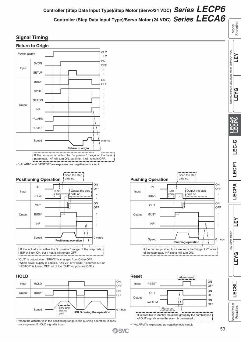
Power supply
SVON
SETUP
BUSY
SVRE
SETON
INP
ALARM
ESTOP
Input
Output
Speed
Return to origin
24 V 0 V
ONOFF
0 mm/s
ONOFF
IN
DRIVE
OUT
BUSY
INP
Input
Output
SpeedPositioning operation
ONOFF
0 mm/s
ONOFF
If the actuator is within the “in position” range of the basic parameter, INP will turn ON, but if not, it will remain OFF.
“ ALARM” and “ ESTOP” are expressed as negative-logic circuit.
When the actuator is in the positioning range in the pushing operation, it does not stop even if HOLD signal is input. “ ALARM” is expressed as negative-logic circuit.
“OUT” is output when “DRIVE” is changed from ON to OFF.(When power supply is applied, “DRIVE” or “RESET” is turned ON or “ ESTOP” is turned OFF, all of the “OUT” outputs are OFF.)
Scan the stepdata no.
Output the stepdata no.
If the actuator is within the “in position” range of the step data, INP will turn ON, but if not, it will remain OFF.
HOLD
BUSY
Input
Output
SpeedHOLD during the operation
ONOFF
0 mm/s
ONOFF
If the current pushing force exceeds the “trigger LV” value of the step data, INP signal will turn ON.
IN
DRIVE
OUT
BUSY
INP
Input
Output
SpeedPushing operation
ONOFF
0 mm/s
ONOFF
Scan the stepdata no.
Output the stepdata no.
Slow-downstartingpoint
RESET
OUT
ALARM
Input
Output
ONOFF
ONOFF
ONOFF
Alarm out
Alarm reset
It is possible to identify the alarm group by the combination of OUT signals when the alarm is generated.
15 msor more
15 msor more
Signal Timing
Return to Origin
Positioning Operation
HOLD Reset
Pushing Operation
53
Controller (Step Data Input Type)/Step Motor (Servo/24 VDC) Series LECP6Controller (Step Data Input Type)/Servo Motor (24 VDC) Series LECA6
LE
YL
EC
SL
EC
A6
LE
CP
6L
EC
-GL
EC
P1
LE
CP
AL
EY
GL
EY
LE
YG
Mod
elS
elec
tion
Ser
vo M
otor
(24
VD
C)/S
tep
Mot
or (S
ervo
/24
VD
C)
AC
Ser
vo M
otor
Spec
ific P
rodu
ctPr
ecau
tions

(17.
7)(1
7.7)
(30.7)Connector A
L (11)
(30.7) L (11)
(14.2) (Terminal no.)
(14)
(18)
(14.2)
(14)
(18)
A1 B1
A6 B6
1 25 6
1 2
15 16
(ø8)(Terminal no.)
Connector C
Connector A
(ø5.
5)(ø
6.3)
(Terminal no.)
1 25 6
1 2
15 16
Controller side
A1 B1
A6 B6
(Terminal no.)
Actuator side
Actuator side
Controller side
(13.5)
(10)Connector D
Connector C
Connector D(14.7)
(13.5)
(10)
(14.7)
B1(Terminal no.)
B6
A1
A6B1B3
A1A3
B1(Terminal no.)
B6
A1
A6
B1B3
A1A3
(ø8)
(ø5.
7)
(17.
7)(1
0.2)
(30.7) L (11)
(14.2)
(14)
(18)
(ø5.
5)
(ø6.
3)(ø
5.7)
(17.
7)(1
0.2)
(30.7) L (11)
(14.2)
(14)
(18)
Actuator side Controller side
Actuator sideController side
(Terminal no.)
(Terminal no.)
Connector A
Connector B
Connector A
Connector B
Connector C
Connector D
Connector C
Connector D
(14.7)
(14.7)
1 25 6
1 2
15 16
(13.5)
(10)
1 25 6
1 2
15 16
(13.5)
(10)
Options: Actuator Cable
[Robotic cable, standard cable for step motor (Servo/24 VDC)]
LE CP 1
Cable length (L) [m]1358ABC
1.5358
101520
Connector Aterminal no.
B-1A-1B-2A-2B-3A-3
AABB
COM-A/COMCOM-B/—
B-4A-4B-5A-5B-6A-6
VccGND
AABB
Signal Cable color
BrownRed
OrangeYellowGreenBlue
BrownBlackRed
BlackOrangeBlack
—
Connector Cterminal no.
Cable color Connector Dterminal no.
216534
121376983
LE-CP- /Cable length: 1.5 m, 3 m, 5 m135
LE-CP- /Cable length: 8 m, 10 m, 15 m, 20 m( Produced upon receipt of order)
8A
BC
Produced upon receipt of order (Robotic cable only)
Cable type
Shield
Connector Aterminal no.
B-1A-1B-2A-2B-3A-3
AABB
COM-A/COMCOM-B/—
B-1A-1B-3A-3
Lock (+)Lock ( )
Sensor (+) Note)
Sensor ( ) Note)
B-4A-4B-5A-5B-6A-6
VccGND
AABB
Signal
Connector Bterminal no.Signal
Cable color
BrownRed
OrangeYellowGreenBlue
BrownBlackRed
BlackOrangeBlack
—
Connector Cterminal no.
Cable color Connector Dterminal no.
216534
121376983
RedBlackBrownBlue
4512
Shield
[Robotic cable, standard cable with lock and sensor for step motor (Servo/24 VDC)]
LE-CP- /Cable length: 1.5 m, 3 m, 5 m135
LE-CP- /Cable length: 8 m, 10 m, 15 m, 20 m( Produced upon receipt of order)
8A
BC
LE CP 1 B
Cable length (L) [m]
With lock and sensor
1358ABC
1.5358
101520
Produced upon receipt of order (Robotic cable only)
Note) Not used for the LE series.
Nil
S
Robotic cable(Flexible cable)
Standard cable
Cable type
Nil
S
Robotic cable(Flexible cable)
Standard cable
54
Series LECP6Series LECA6

Controller side
Actuator side(Terminal no.)
(Terminal no.)(16.6) (23.7)
(30.7) (11)L
3
1
2 1
(14.7)
4
A(1
2.7)
(5.6
)
Connector B
Connector A
(ø7.
0)(ø
6.7)
Connector C (14.2)
(10.
5)(1
8)
Connector D
13
24
1 2
15 16
(13.5)
(10)
B
Controller sideActuator side
(Terminal no.)
(Terminal no.)
(16.6)(23.7)
(30.7)
(30.7) (11)L
3
1
2 1
4
13
(12.
7)(1
0.2)
(5.6
)
Connector B
Connector A1
(ø7.
0)
(ø6.
7)(ø
5.7)
Connector C (14.2)
(10.
5)(1
8)
Connector D
13
24
1 2
15 16
(13.5)
(10)
AB
AB
(14.7)
Connector A2
[Robotic cable for servo motor (24 VDC)]
LE CA 1
Cable length (L) [m]1358ABC
1.5358
101520
LE-CA-
Connector Aterminal no.
123
UVW
Signal Cable color
RedWhiteBlack
Connector Cterminal no.
123
Connector Bterminal no.
B-1A-1B-2A-2B-3A-3B-4A-4
VccGND
AABBZZ
Signal Cable color
BrownBlackRed
BlackOrangeBlackYellowBlack
—
Connector Dterminal no.
12137698
11103
Shield
Connector A1terminal no.
123
UVW
Signal
Connector Bterminal no.
B-1A-1B-3A-3
Lock (+)Lock ( )
Sensor (+) Note)
Sensor ( ) Note)Note) Not used for the LE series.
Signal
Cable color
RedWhiteBlack
Connector Cterminal no.
123
Connector A2terminal no.
B-1A-1B-2A-2B-3A-3B-4A-4
VccGND
AABBZZ
Signal Cable color
BrownBlackRed
BlackOrangeBlackYellowBlack
—
Connector Dterminal no.
12137698
11103
RedBlackBrownBlack
4512
Shield
Connection of shield material
Connection of shield material
Produced upon receipt of order
[Robotic cable with lock and sensor for servo motor (24 VDC)]
LE CA 1 B
1358ABC
1.5358
101520
LE-CA- -B
Produced upon receipt of order
Cable length (L) [m]
With lock and sensor
55
Controller (Step Data Input Type)/Step Motor (Servo/24 VDC) Series LECP6Controller (Step Data Input Type)/Servo Motor (24 VDC) Series LECA6
LE
YL
EC
SL
EC
A6
LE
CP
6L
EC
-GL
EC
P1
LE
CP
AL
EY
GL
EY
LE
YG
Mod
elS
elec
tion
Ser
vo M
otor
(24
VD
C)/S
tep
Mot
or (S
ervo
/24
VD
C)
AC
Ser
vo M
otor
Spec
ific P
rodu
ctPr
ecau
tions

(22.
4)
(14.4) L
B1 A1
B13 A13
A1
B13
A13B1
Controller side PLC side
(ø8.
9)
(Terminal no.)
(42.2) (28.8)
(33.
5)
(12.
5)
Option: I/O Cable
Option: Noise Filter Set for Servo Motor (24 VDC)
LEC CN5 1
LEC NFA
Cable length (L) [m]135
1.535
A1
Dotcolor
Dotmark
Insulationcolor
Connectorpin no.
A2A3A4A5A6A7A8A9A10A11A12A13
— Shield
Dotcolor
Dotmark
Insulationcolor
Connectorpin no.
B1B2B3B4B5B6B7B8B9B10B11B12B13
Conductor size: AWG28
Refer to the LECA6 series Operation Manual for installation.
Contents of the set: 2 noise filters (Manufactured by WURTH ELEKTRONIK: 74271222)
Light brownLight brownYellowYellowLight greenLight greenGrayGrayWhiteWhite
Light brownLight brownYellow
BlackRed
BlackRed
BlackRed
BlackRed
BlackRed
BlackRed
Black
YellowLight greenLight greenGrayGrayWhiteWhite
Light brownLight brownYellowYellowLight greenLight green
RedBlackRed
BlackRed
BlackRed
BlackRed
BlackRed
BlackRed
56
Series LECP6Series LECA6

HRS
PC
Controller settingsoftware
Communicationcable USB cable
(A-miniB type)
How to Order
Contents
Controller setting software (CD-ROM)
Communication cable
USB cable (Cable between the PC and the conversion unit)
LEC W2Controller setting kit
(Japanese and English are available.)
Easy operation and simple settingAllowing to set and display actuator step data such as position, speed, force, etc.Setting of step data and testing of the drive can be performed on the same page.Can be used to jog and move at a constant rate.
Detailed settingStep data can be set in detail.Signals and terminal status can be monitored.Parameters can be set.JOG and constant rate movement, return to origin, test operation and testing of forced output can be performed.
Series LECController Setting Kit/LEC-W2
Screen Example
Easy mode screen example Normal mode screen example
Compatible Controllers/Driver
Step motor controller (Servo/24 VDC) Series LECP6Servo motor controller (24 VDC) Series LECA6Step motor driver (Pulse input type) Series LECPA
Hardware Requirements
Display
Communicationinterface
OS
XGA (1024 x 768) or more
USB 1.1 or USB 2.0 ports
IBM PC/AT compatible machine runningWindows®XP (32-bit),Windows®7 (32-bit and 64-bit).
Windows® and Windows®7 are registered trademarks of Microsoft Corporation in the United States. Refer to SMC website for version update information, http://www.smcworld.com
57
Windows®XP, Windows®7 compatible
LE
YL
EC
SL
EC
A6
LE
CP
6L
EC
-GL
EC
P1
LE
CP
AL
EY
GL
EY
LE
YG
Mod
elS
elec
tion
Ser
vo M
otor
(24
VD
C)/S
tep
Mot
or (S
ervo
/24
VD
C)
AC
Ser
vo M
otor
Spec
ific P
rodu
ctPr
ecau
tions
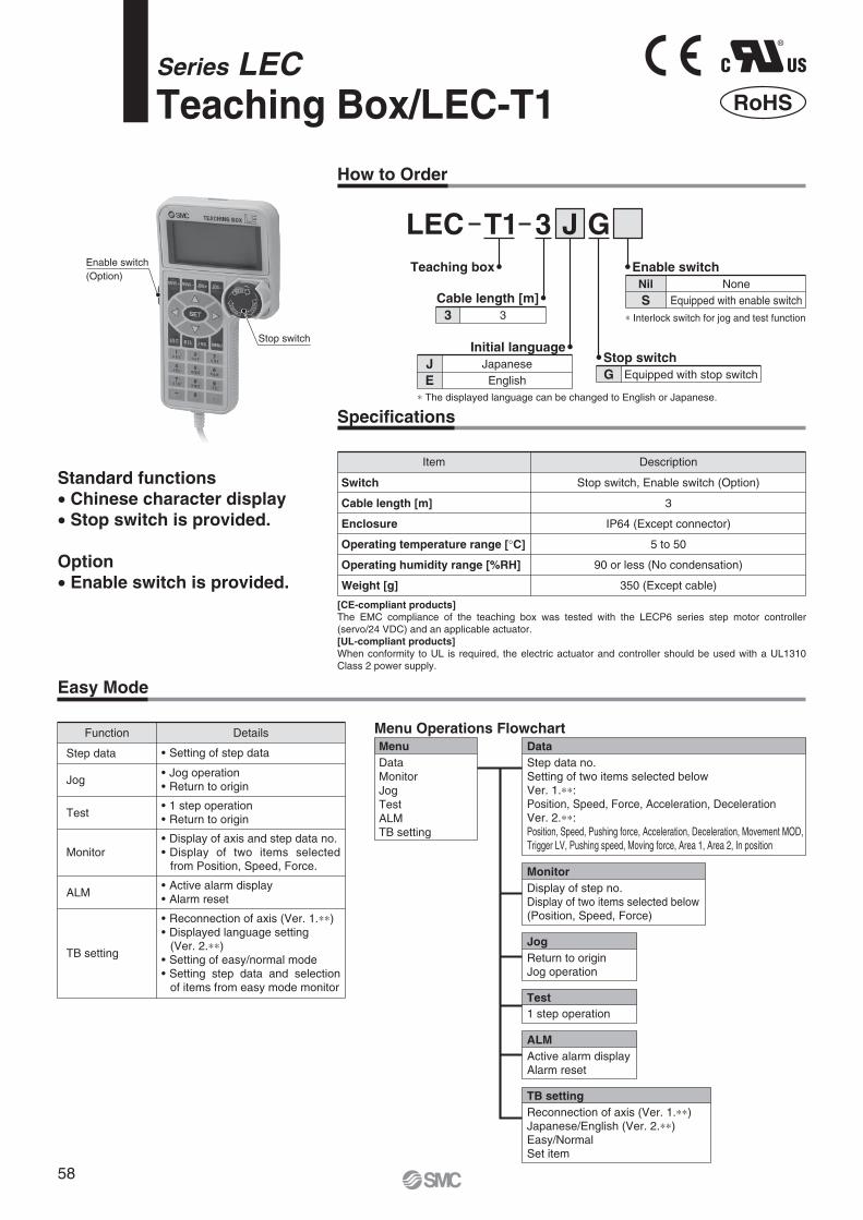
How to Order
Specifications
LEC T1 3 J GEnable switch
SNone
Equipped with enable switchNil
Teaching box
Cable length [m]
Stop switchG Equipped with stop switch
Initial language
Item
Switch
Cable length [m]
Enclosure
Operating temperature range [ C]
Operating humidity range [%RH]
Weight [g]
Stop switch, Enable switch (Option)
3
IP64 (Except connector)
5 to 50
90 or less (No condensation)
350 (Except cable)
Description
Easy Mode
Standard functions Chinese character display Stop switch is provided.
Option Enable switch is provided.
Function
Step data
Jog
Test
Monitor
ALM
TB setting
Details
Jog operation Return to origin
Setting of step data
1 step operation Return to origin
Display of axis and step data no.
from Position, Speed, Force.
Active alarm display Alarm reset
Reconnection of axis (Ver. 1. ) Displayed language setting(Ver. 2. )
Setting of easy/normal mode Setting step data and selection of items from easy mode monitor
MenuDataMonitorJogTestALMTB setting
JogReturn to originJog operation
Test1 step operation
ALMActive alarm displayAlarm reset
TB settingReconnection of axis (Ver. 1. )Japanese/English (Ver. 2. )Easy/NormalSet item
DataStep data no.Setting of two items selected belowVer. 1. :Position, Speed, Force, Acceleration, DecelerationVer. 2. :Position, Speed, Pushing force, Acceleration, Deceleration, Movement MOD, Trigger LV, Pushing speed, Moving force, Area 1, Area 2, In position
MonitorDisplay of step no.Display of two items selected below(Position, Speed, Force)
Menu Operations Flowchart
Interlock switch for jog and test function
Enable switch(Option)
Stop switch
[CE-compliant products]The EMC compliance of the teaching box was tested with the LECP6 series step motor controller (servo/24 VDC) and an applicable actuator.[UL-compliant products]When conformity to UL is required, the electric actuator and controller should be used with a UL1310 Class 2 power supply.
Series LECTeaching Box/LEC-T1
®
RoHS
3 3
JE
JapaneseEnglish
The displayed language can be changed to English or Japanese.
58

185
1024
25 22.5
34.5
Normal Mode
Dimensions
No.
1
2
3
4
5
6
7
8
LCD
Ring
Stop switch
Stop switch guard
Enable switch(Option)
Key switch
Cable
Connector
A screen of liquid crystal display (with backlight)
A ring for hanging the teaching box
A guard for the stop switch
Switch for each input
Length: 3 meters
A connector connected to CN4 of the controller
When switch is pushed in, the switch locks and stops.The lock is released when it is turned to the right.
FunctionDescription
Prevents unintentional operation (unexpected operation) of the jog test function.Other functions such as data change are not covered.
MenuStep dataParameterMonitorTestALMFileTB settingReconnect
Step dataStep data no.Movement MODSpeedPositionAccelerationDecelerationPushing forceTrigger LVPushing speedMoving forceArea 1, 2In position
ParameterBasicORIG
DRV monitorPosition, Speed, TorqueStep no.Last step no.
StatusActive alarm displayAlarm reset
ALM Log record displayLog entry display
MonitorDriveOutput signalInput signalOutput terminalInput terminal
TestJOG/MOVEReturn to ORIGTest driveForced output
ALMStatusALM Log record
TB settingEasy/NormalLanguageBacklightLCD contrastBeepMax. connection axisPasswordDistance unit
Reconnect
Basic setting
ORIG setting
Output signal monitor
Input signal monitor
Output terminal monitor
Input terminal monitor
Menu Operations FlowchartFunction
Step data
Parameter
Test
Monitor
ALM
TB setting
Reconnect
Details
Jog operation/Constant rate movement
(Specify a maximum of 5 step data and operate.)Forced output(Forced signal output, Forced terminal output)
(Alarm reset)
Save the step data and parameters of the controller which is being used for communication (it is possible to save four files, with one set of step data and parameters defined as one file).
Loads the data which is saved in the teaching box to the controller which is being used for communication.
File protection (Ver. 2. )
(Easy/Normal mode)
(Japanese/English)
File
FileData savingLoad to controllerFile deletionFile protection (Ver. 2. )
59
Teaching Box Series LEC
LE
YL
EC
SL
EC
A6
LE
CP
6L
EC
-GL
EC
P1
LE
CP
AL
EY
GL
EY
LE
YG
Mod
elS
elec
tion
Ser
vo M
otor
(24
VD
C)/S
tep
Mot
or (S
ervo
/24
VD
C)
AC
Ser
vo M
otor
Spec
ific P
rodu
ctPr
ecau
tions

How to Order
Specifications
Model LEC-GMJ2 LEC-GDN1 LEC-GPR1 LEC-GEN1CC-LinkVer. 2.0
156 k/625 k/2.5 M/5 M/10 M
—
——
Connector (Accessory)Not included
24 VDC 10%200300
30 VDC 1 ASeries LECP6, Series LECA6
115.2 k/230.4 k
0 to 40 (No freezing)90 or less (No condensation)
10 to 60 (No freezing)90 or less (No condensation)
200 (Screw mounting), 220 (DIN rail mounting)
DeviceNet™Release 2.0
125 k/250 k/500 k
EDS file
Input 200 bytesOutput 200 bytes
11 to 25 VDC100
Connector (Accessory)Not included
PROFIBUS DPV1
9.6 k/19.2 k/45.45 k/93.75 k/187.5 k/500 k/1.5 M/3 M/6 M/12 M
GSD file
Input 57 wordsOutput 57 words
——
D-subNot included
EtherNet/IP™Release 1.0
10 M/100 M
EDS file
Input 256 bytesOutput 256 bytes
——
RJ45Not included
12Power supply connector, communication connector Power supply connector
8 Note 5) 5 12
Power supply voltage [V] Note 6)
Currentconsumption [mA]EMG output terminal
Controllerspecifications
AccessoriesOperating temperature range [ C]Operating humidity range [%RH]Storage temperature range [ C]Storage humidity range [%RH]Weight [g]
Communication speed [bps]
Configuration file Note 2)
I/O occupation area
Power supply for communicationCommunication connector specificationsTerminating resistor
Not connected to teaching boxConnected to teaching box
Applicable controllersCommunication speed [bps] Note 3)
Max. number of connectable controllers Note 4)
Applicable systemFieldbusVersion Note 1)
Power supply voltage [V] Note 6)
Internal current consumption [mA]
LEC GGateway unitApplicable Fieldbus protocols
MJ2DN1PR1EN1
CC-Link Ver. 2.0DeviceNet™
PROFIBUS DPEtherNet/IP™
MountingNil
D Note)
Screw mountingDIN rail mounting
LEC CGCable
Cable lengthKL1
0.3 m0.5 m1 m
Branch connector
L1Cable type
12
Communication cableCable between branches
LEC CGDBranch connector
Cable between branches
Communication cable
MJ2
Note 1) Please note that the version is subject to change.Note 2) Each file can be downloaded from the SMC website, http://www.smcworld.comNote 3) When using a teaching box (LEC-T1- ), set the communication speed to 115.2 kbps.Note 4) A communication response time for 1 controller is approximately 30 ms.
Refer to “Communication Response Time Guideline” for response times when several controllers are connected.Note 5) For step data input, up to 12 controllers connectable.Note 6) When conformity to UL is required, the electric actuator and controller should be used with a UL1310 Class 2 power supply.
4 stationsoccupied(8 timessetting)
Input 896 points108 words
Output 896 points108 words
Communicationspecifications
®
RoHS
Gateway Unit
Series LEC-G[CE-compliant products]EMC compliance was tested by combining the electric actuator LE series and the controller LE series.The EMC depends on the configuration of the customer’s control panel and the relationship with other electrical equipment and wiring. Therefore conformity to the EMC directive cannot be certified for SMC components incorporated into the customer’s equipment under actual operating conditions. As a result it is necessary for the customer to verify conformity to the EMC directive for the machinery and equipment as a whole.[UL-compliant products]When conformity to UL is required, the electric actuator and controller should be used with a UL1310 Class 2 power supply.
Caution
Note) DIN rail is not included. Order it separately.
LEC CGRTerminating resistor
60

170
152.
2
161
31(35)
18.2
4.5For body mounting
(85)82
1
ø4.5For body mounting
ø4.5For body mounting
ø4.5For body mounting
ø4.5For body mounting
18.2
4.5For body mounting
4.5For body mounting
4.5For body mounting
170
152.
2
161
(35)
31
18.2
182
(85)
170
152.
2
161
(35)31
1
(87.9)82
170
152.
2
161
(35)
31
18.2
(85)82
1
Screw mounting (LEC-G )
Applicable Fieldbus protocol: CC-Link Ver. 2.0 Applicable Fieldbus protocol: DeviceNet™
Applicable Fieldbus protocol: PROFIBUS DP Applicable Fieldbus protocol: EtherNet/IP™
Dimensions
Response time between gateway unit and controllers depends on the number of controllers connected to the gateway unit.For response time, refer to the graph below.
This graph shows delay times between gateway unit and controllers.Fieldbus network delay time is not included.Number of connectable controllers (unit)
Res
pons
e tim
e (m
s)
1 2 3 4 5 6 7 8 9 10 11 12
400
350
300
250
200
150
100
50
0
Trademark DeviceNet™ is a trademark of ODVA. EtherNet/IP™ is a trademark of ODVA.
Communication Response Time Guideline
61
Gateway Unit Series LEC-G
LE
YL
EC
SL
EC
A6
LE
CP
6L
EC
-GL
EC
P1
LE
CP
AL
EY
GL
EY
LE
YG
Mod
elS
elec
tion
Ser
vo M
otor
(24
VD
C)/S
tep
Mot
or (S
ervo
/24
VD
C)
AC
Ser
vo M
otor
Spec
ific P
rodu
ctPr
ecau
tions

193.
2 (W
hen
rem
ovin
g D
IN r
ail)
187.
3 (W
hen
lock
ing
DIN
rai
l)
170
152.
2
161
(35)31
(85)82
1
64.2
35
(95)
193.
2 (W
hen
rem
ovin
g D
IN r
ail)
187.
3 (W
hen
lock
ing
DIN
rai
l)
170
152.
2
161
(35)31
(85)82
1
64.2
35
(95)
193.
2 (W
hen
rem
ovin
g D
IN r
ail)
187.
3 (W
hen
lock
ing
DIN
rai
l)
170
152.
2
(35)31
161
(87.9)82
1
64.2
35
(98)
193.
2 (W
hen
rem
ovin
g D
IN r
ail)
187.
3 (W
hen
lock
ing
DIN
rai
l)
170
152.
2
161
(35)31
(85)82
1
(95)
Mountable on DIN rail (35 mm) Mountable on DIN rail (35 mm)
Mountable on DIN rail (35 mm)
64.2
35
Mountable on DIN rail (35 mm)
DIN rail mounting (LEC-G D)
Applicable Fieldbus protocol: CC-Link Ver. 2.0 Applicable Fieldbus protocol: DeviceNet™
Applicable Fieldbus protocol: PROFIBUS DP Applicable Fieldbus protocol: EtherNet/IP™
DIN railAXT100-DR-
For , enter a number from the “No.” line in the table below.Refer to the dimensions above for the mounting dimensions.
40
510.5
39
498
38
485.5
37
473
36
460.5
35
448
34
435.5
33
423
32
410.5
31
398
30
385.5
29
373
28
360.5
27
348
26
335.5
25
323
24
310.5
23
298
22
285.5
21
273
No.
L
20
260.5
19
248
18
235.5
17
223
16
210.5
15
198
14
185.5
13
173
12
160.5
11
148
10
135.5
9
123
8
110.5
7
98
6
85.5
5
73
4
60.5
3
48
2
35.5
1
23
No.
L
L Dimension [mm]
7.5
(25)
(35)
L
5.5
5.2512.5 (Pitch)
1.25
Trademark DeviceNet™ is a trademark of ODVA. EtherNet/IP™ is a trademark of ODVA.
Dimensions
62
Series LEC-G

[CE-compliant products]EMC compliance was tested by combining the electric actuator LEY series and the controller LEC series.The EMC depends on the configuration of the customer’s control panel and the relationship with other electrical equipment and wiring. Therefore conformity to the EMC directive cannot be certified for SMC components incorporated into the customer’s equipment under actual operating conditions. As a result it is necessary for the customer to verify conformity to the EMC directive for the machinery and equipment as a whole.[UL-compliant products]When conformity to UL is required, the electric actuator and controller should be used with a UL1310 Class 2 power supply.
Caution
C 1LE N 1PController
Compatible motorP Step motor (Servo/24 VDC)
Number of step data (Points)1 14 (Programless)
Parallel I/O typeNP
NPNPNP
I/O cable length [m]Nil135
Without cable1.535
Actuator part number(Except cable specifications and actuator options)Example: Enter “LEY16B-100” for the
LEY16B-100B-R11N1.
When controller equipped type is selected when ordering the LE series, you do not need to order this controller.
OptionNil
D Note)Screw mountingDIN rail mounting
LEY16B-100
How to Order
Programless Controller
Series LECP1
®
RoHS
The controller is sold as single unit after the compatible actuator is set.Confirm that the combination of the controller and the actuator is correct.
Refer to the operation manual for using the products. Please download it via our website, http://www.smcworld.com
Specifications
Basic SpecificationsItem LECP1
Step motor (Servo/24 VDC)Power supply voltage: 24 VDC 10%, Max. current consumption: 3A (Peak 5A) Note 2)
[Including the motor drive power, control power supply, stop, lock release]6 inputs (Photo-coupler isolation)
6 outputs (Photo-coupler isolation)14 points (Position number 1 to 14(E))
Incremental A/B phase (800 pulse/rotation)EEPROM
LED (Green/Red) one of each1 digit, 7-segment display (Red) Figures are expressed in hexadecimal (“10” to “15” in decimal number are expressed as “A” to “F”)
Forced-lock release terminal Note 4)
I/O cable: 5 or less, Actuator cable: 20 or lessNatural air cooling
0 to 40 (No freezing)90 or less (No condensation)
10 to 60 (No freezing)90 or less (No condensation)
Between the housing and SG terminal: 50 (500 VDC)130 (Screw mounting), 150 (DIN rail mounting)
Note 4) Applicable to non-magnetizing lock.
Decimal display
Hexadecimal display
10
A
11
b
12
c
13
d
14
E
15
F
Note 1) Do not use the power supply of “inrush current prevention type” for the controller input power supply. When conformity to UL is required, the electric actuator and controller should be used with a UL1310 Class 2 power supply.
Note 2) The power consumption changes depending on the actuator model. Refer to the each actuator’s operation manual etc. for details.Note 3) “10” to “15” in decimal number are displayed as follows in the 7-segment LED.
Note) DIN rail is not included. Order it separately.
Compatible motor
Power supply Note 1)
Parallel inputParallel outputStop pointsCompatible encoderMemoryLED indicator7-segment LED display Note 3)
Lock controlCable length [m]Cooling systemOperating temperature range [ C]Operating humidity range [%RH]Storage temperature range [ C]Storage humidity range [%RH]Insulation resistance [M ]Weight [g]
63
LE
YL
EC
SL
EC
A6
LE
CP
6L
EC
-GL
EC
P1
LE
CP
AL
EY
GL
EY
LE
YG
Spec
ific P
rodu
ctPr
ecau
tions
AC
Ser
vo M
otor
Ser
vo M
otor
(24
VD
C)/S
tep
Mot
or (S
ervo
/24
VD
C)
Mod
elS
elec
tion
LE
YL
EC
SA
C S
ervo
Mot
orL
EC
A6
LE
CP
6L
EC
-GL
EC
P1
LE
CP
AL
EY
GL
EY
LE
YG
Spec
ific P
rodu
ctPr
ecau
tions
Ser
vo M
otor
(24
VD
C)/S
tep
Mot
or (S
ervo
/24
VD
C)
Mod
elS
elec
tion

Display
PWR
ALM
—
—
—
—
SET
—
MANUAL
SPEED
ACCEL
CN1
CN2
CN3
CN4
Description
Power supply LED
Alarm LED
Cover
FG
Mode switch
7-segment LED
Set button
Position selecting switch
Manual forward button
Manual reverse button
Forward speed switch
Reverse speed switch
Forward acceleration switch
Reverse acceleration switch
Power supply connector
Motor connector
Encoder connector
I/O connector
Details
Power supply ON/Servo ON : Green turns onPower supply ON/Servo OFF: Green flashes
With alarm : Red turns onParameter setting : Red flashes
Change and protection of the mode switch(Close the cover after changing switch)
Frame ground (Tighten the bolt with the nut when mounting the controller. Connect the ground wire.)
Switch the mode between manual and auto.
Stop position, the value set by and alarm information are displayed.
Decide the settings or drive operation in Manual mode.
Assign the position to drive (1 to 14), and the origin position (15).
Perform forward jog and inching.
Perform reverse jog and inching.
16 forward speeds are available.
16 reverse speeds are available.
16 forward acceleration steps are available.
16 reverse acceleration steps are available.
Connect the power supply cable.
Connect the motor connector.
Connect the encoder connector.
Connect I/O cable.
No.
Controller Details
CautionM4 screws, cable with crimping terminal and tooth lock washer are not included.Be sure to carry out grounding earth in order to ensure the noise tolerance.
Use a watchmaker’s screwdriver of the size shown below when changing position switch and the set value of the speed/acceleration switch to .
SizeEnd width L: 2.0 to 2.4 [mm]End thickness W: 0.5 to 0.6 [mm]
How to Mount
Controller mounting shown below.
1. Mounting screw (LECP1 - )(Installation with two M4 screws)
2. GroundingTighten the bolt with the nut when mounting the ground wireas shown below.
L
W
Magnified view of the endof the screwdriver
Mounting direction
Mounting direction
Ground wireM4 screw
Cable with crimping terminal
Tooth lock washer
ControllerNote) When size 25 or more of the LEY series are used, the space between the controllers should be 10 mm or more.
64
Series LECP1

ø4.5for body mounting
101
110
86
38
4.5for body mounting
36.2
18.1
85
1.24.
5
CN4 I/O connector
CN1 power supply connector
CN3 encoder connector
CN2 motor connector
Dimensions
SL
110
127.
3 (W
hen
lock
ing
DIN
rai
l)
133.
2 (W
hen
rem
ovin
g D
IN r
ail)
86
38
36.2 85 (11.5)
24.2
35
Screw mounting (LEC 1 - )
DIN rail mounting (LEC 1 D- )
65
Programless Controller Series LECP1
LE
YL
EC
SA
C S
ervo
Mot
orL
EC
A6
LE
CP
6L
EC
-GL
EC
P1
LE
CP
AL
EY
GL
EY
LE
YG
Spec
ific P
rodu
ctPr
ecau
tions
Ser
vo M
otor
(24
VD
C)/S
tep
Mot
or (S
ervo
/24
VD
C)
Mod
elS
elec
tion

Wiring Example 1
NPN PNP
Wiring Example 2
Parallel I/O Connector: CN4 When you connect a PLC, etc., to the CN4 parallel I/O connector, please use the I/O cable (LEC-CK4- ). The wiring should be changed depending on the type of the parallel I/O (NPN or PNP).
Power Supply Connector: CN1 When you connect a CN1 power supply connector, please use the power supply cable (LEC-CK1-1). Power supply cable (LEC-CK1-1) is an accessory.
M24V terminal/C24V terminal/BK RLS terminal are common ( ).
Motor power supply (+) supplied to the controller
Control power supply (+) supplied to the controller
Terminal name Cable color Function Details
0V
M24V
C24V
BK RLS
Blue
White
Brown
Black
Commonsupply ( )
Motor powersupply (+)
Control powersupply (+)
Lock release (+) Input (+) for releasing the lock
Name
COM+
COM
IN0 to IN3
RESET
STOP
Connects the power supply 24 V for input/output signal
Connects the power supply 0 V for input/output signal
Instruction to drive (input as a combination of IN0 to IN3)
Instruction to return to origin (IN0 to IN3 all ON simultaneously) Example - (instruction to drive for position no. 5)
Alarm reset and operation interruption
During operation: deceleration stop from position at which
signal is input (servo ON maintained)
While alarm is active: alarm reset
Instruction to stop (after maximum deceleration stop, servo OFF)
Details
IN0ON
IN1OFF
IN3OFF
IN2ON
Name
OUT0 to OUT3
BUSY
ALARM Note)
Turns on when the positioning or pushing is completed.(Output is instructed in the combination of OUT0 to 3.) Example - (operation complete for position no. 3)
Outputs when the actuator is moving
Not output when alarm is active or servo OFF
Note) Signal of negative-logic circuit (N.C.)
Details
OUT0ON
OUT1ON
OUT3OFF
OUT2OFF
Input Signal
Position number123456789
10 (A)11 (B)12 (C)13 (D)14 (E)
Retun to origin
IN3 IN2 IN1 IN0Input Signal [IN0 - IN3] Position Number Chart : OFF : ON
Position number123456789
10 (A)11 (B)12 (C)13 (D)14 (E)
Retun to origin
OUT3 OUT2 OUT1 OUT0Output Signal [OUT0 - OUT3] Position Number Chart : OFF : ON
Output Signal
CN1 Power Supply Connector Terminal for LECP1 Power supply cable for LECP1 (LEC-CK1-1)
CN41
2
3
4
5
6
7
8
9
10
11
12
13
14
Power supply 24 VDCfor I/O signal
Load
Load
Load
Load
Load
Load
COM+
COM
OUT0
OUT1
OUT2
OUT3
BUSY
ALARM
IN0
IN1
IN2
IN3
RESET
STOP
COM+
COM
OUT0
OUT1
OUT2
OUT3
BUSY
ALARM
IN0
IN1
IN2
IN3
RESET
STOP
1
2
3
4
5
6
7
8
9
10
11
12
13
14
CN4Power supply 24 VDC
for I/O signal
Load
Load
Load
Load
Load
Load
66
Series LECP1

Power supply
IN0-3
BUSY
OUT0-3
ALARM
Input
Output
External lock
Speed
Return to origin
24 V 0 V
24 V 0 V
ReleaseHold
ONOFF
0 mm/s
ONOFF
ReleaseHold
IN0-3
OUT0-3
BUSY
Input
Power supply
Output
External lock
SpeedPositioning operation
ONOFF
0 mm/s
ONOFF
Output signals for OUT0, OUT1, OUT2, OUT3 are ON when return to origin is completed.
ON after controller system initialization
“ ALARM” is expressed as negative-logic circuit.
“ ALARM” is expressed as negative-logic circuit.
OUT0-3 output signals are ON in the same state as the input IN0-3 when positioning is completed.
24 V 0 V
ReleaseHold
IN0-3
RESET
OUT0-3
BUSY
Input
Power supply
Output
External lock
Speed Cut-off stop duringpositioning operation
ONOFF
0 mm/s
ONOFF
24 V 0 V
ReleaseHold
IN0-3
STOP
OUT0-3
BUSY
ALARM
Input
Power supply
Output
External lock
Speed Stop by the STOP signal duringpositioning operation
ONOFF
0 mm/s
ONOFF
RESET
ALARM
Input
Output
ONOFF
ONOFF
Alarm out
Alarm reset
IN0-3 all ON
Signal Timing
(1) Return to Origin
(2) Positioning Operation
(3) Cut-off Stop (Reset Stop)
(4) Stop by the STOP Signal
(5) Alarm Reset
67
Programless Controller Series LECP1
LE
YL
EC
SA
C S
ervo
Mot
orL
EC
A6
LE
CP
6L
EC
-GL
EC
P1
LE
CP
AL
EY
GL
EY
LE
YG
Spec
ific P
rodu
ctPr
ecau
tions
Ser
vo M
otor
(24
VD
C)/S
tep
Mot
or (S
ervo
/24
VD
C)
Mod
elS
elec
tion

(17.
7)(1
7.7)
(30.7)Connector A
L (11)
(30.7) L (11)
(14.2) (Terminal no.)
(14)
(18)
(14.2)
(14)
(18)
A1 B1
A6 B6
1 25 6
1 2
15 16
(ø8)(Terminal no.)
Connector C
Connector A
(ø5.
5)(ø
6.3)
(Terminal no.)
1 25 6
1 2
15 16
Controller side
A1 B1
A6 B6
(Terminal no.)
Actuator side
Actuator side
Controller side
(13.5)
(10)Connector D
Connector C
Connector D(14.7)
(13.5)
(10)
(14.7)
B1(Terminal no.)
B6
A1
A6B1B3
A1A3
B1(Terminal no.)
B6
A1
A6
B1B3
A1A3
(ø8)
(ø5.
7)
(17.
7)(1
0.2)
(30.7) L (11)
(14.2)
(14)
(18)
(ø5.
5)
(ø6.
3)(ø
5.7)
(17.
7)(1
0.2)
(30.7) L (11)
(14.2)
(14)
(18)
Actuator side Controller side
Actuator sideController side
(Terminal no.)
(Terminal no.)
Connector A
Connector B
Connector A
Connector B
Connector C
Connector D
Connector C
Connector D
(14.7)
(14.7)
1 25 6
1 2
15 16
(13.5)
(10)
1 25 6
1 2
15 16
(13.5)
(10)
[Robotic cable, standard cable for step motor (Servo/24 VDC)]
Options: Actuator Cable
LE CP 1
Cable length (L) [m]1358ABC
1.5358
101520
Connector Aterminal no.
B-1A-1B-2A-2B-3A-3
AABB
COM-A/COMCOM-B/—
B-4A-4B-5A-5B-6A-6
VccGND
AABB
Signal Cable color
BrownRed
OrangeYellowGreenBlue
BrownBlackRed
BlackOrangeBlack
—
Connector Cterminal no.
Cable color Connector Dterminal no.
216534
121376983
LE-CP- /Cable length: 1.5 m, 3 m, 5 m135
LE-CP- /Cable length: 8 m, 10 m, 15 m, 20 m( Produced upon receipt of order)
8A
BC
Produced upon receipt of order (Robotic cable only)
Cable type
Shield
Connector Aterminal no.
B-1A-1B-2A-2B-3A-3
AABB
COM-A/COMCOM-B/—
B-1A-1B-3A-3
Lock (+)Lock ( )
Sensor (+) Note)
Sensor ( ) Note)
B-4A-4B-5A-5B-6A-6
VccGND
AABB
Signal
Connector Bterminal no.Signal
Cable color
BrownRed
OrangeYellowGreenBlue
BrownBlackRed
BlackOrangeBlack
—
Connector Cterminal no.
Cable color Connector Dterminal no.
216534
121376983
RedBlackBrownBlue
4512
Shield
[Robotic cable, standard cable with lock and sensor for step motor (Servo/24 VDC)]
LE-CP- /Cable length: 1.5 m, 3 m, 5 m135
LE-CP- /Cable length: 8 m, 10 m, 15 m, 20 m( Produced upon receipt of order)
8A
BC
LE CP 1 B
Cable length (L) [m]
With lock and sensor
1358ABC
1.5358
101520
Produced upon receipt of order (Robotic cable only)
Note) Not used for the LE series.
Nil
S
Robotic cable(Flexible cable)
Standard cable
Cable type
Nil
S
Robotic cable(Flexible cable)
Standard cable
68
Series LECP1

(10.5)
(15.
8)
Dot color
Black
Red
Black
Red
Black
Red
Black
Red
Black
Red
Black
Red
Black
Red
Function
COM+
COM
OUT0
OUT1
OUT2
OUT3
BUSY
ALARM
IN0
IN1
IN2
IN3
RESET
STOP
Parallel I/O signal is valid in auto mode. While the test function operates at manual mode, only the output is valid.
Conductor size: AWG20
Conductor size: AWG26Dot markInsulation color
Light brown
Light brown
Yellow
Yellow
Light green
Light green
Gray
Gray
White
White
Light brown
Light brown
Yellow
Yellow
Terminal no.
1
2
3
4
5
6
7
8
9
10
11
12
13
14
LEC CK4
Options
[I/O cable]
LEC CK1 1
[Power supply cable]
(13.3) (35) (60)
(1500)
Terminal name Covered color Function0V
M24VC24V
BK RLS
BlueWhiteBrownBlack
Common supply ( )Motor power supply (+)Control power supply (+)Lock release (+)
Cable length (L) [m]135
1.535
(10) (11) (30) (60)
(16)
(L)
Controller side PLC side
(ø7.
9)(ø
6)
69
Programless Controller Series LECP1
LE
YL
EC
SA
C S
ervo
Mot
orL
EC
A6
LE
CP
6L
EC
-GL
EC
P1
LE
CP
AL
EY
GL
EY
LE
YG
Spec
ific P
rodu
ctPr
ecau
tions
Ser
vo M
otor
(24
VD
C)/S
tep
Mot
or (S
ervo
/24
VD
C)
Mod
elS
elec
tion
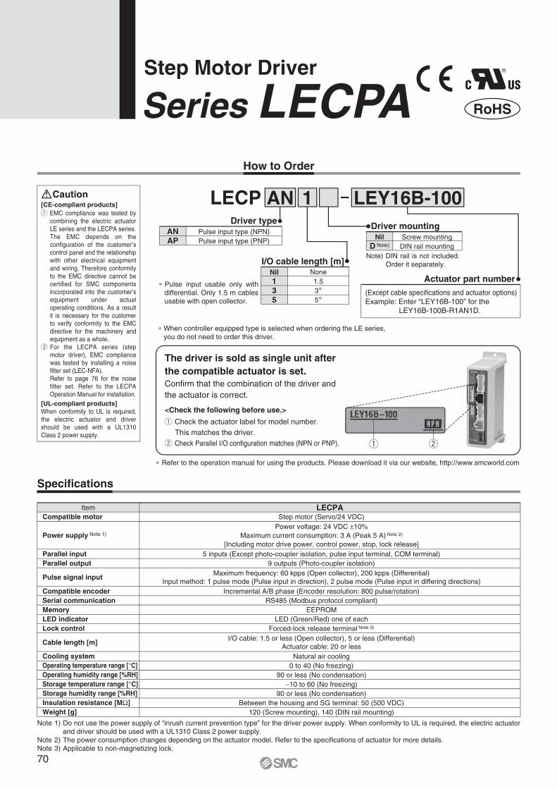
Actuator part number(Except cable specifications and actuator options)Example: Enter “LEY16B-100” for the
LEY16B-100B-R1AN1D.
Driver mountingNil
D Note)Screw mountingDIN rail mounting
ANAP
Pulse input type (NPN)Pulse input type (PNP)
Driver type
Specifications
Nil135
None1.535
I/O cable length [m]
Pulse input usable only with differential. Only 1.5 m cables usable with open collector.
Note 1) Do not use the power supply of “inrush current prevention type” for the driver power supply. When conformity to UL is required, the electric actuator and driver should be used with a UL1310 Class 2 power supply.
Note 2) The power consumption changes depending on the actuator model. Refer to the specifications of actuator for more details.Note 3) Applicable to non-magnetizing lock.
Item LECPACompatible motor
Parallel inputParallel output
Pulse signal input
Compatible encoderSerial communicationMemoryLED indicatorLock control
Cable length [m]
Cooling systemOperating temperature range [ C]Operating humidity range [%RH]Storage temperature range [ C]Storage humidity range [%RH]Insulation resistance [M ]Weight [g]
Power supply Note 1)
[CE-compliant products] EMC compliance was tested by combining the electric actuator LE series and the LECPA series.The EMC depends on the configuration of the customer’s control panel and the relationship with other electrical equipment and wiring. Therefore conformity to the EMC directive cannot be certified for SMC components incorporated into the customer’s equipment under actual operating conditions. As a result it is necessary for the customer to verify conformity to the EMC directive for the machinery and equipment as a whole.
For the LECPA series (step motor driver), EMC compliance was tested by installing a noise filter set (LEC-NFA).Refer to page 76 for the noise filter set. Refer to the LECPA Operation Manual for installation.
[UL-compliant products]When conformity to UL is required, the electric actuator and driver should be used with a UL1310 Class 2 power supply.
Caution
How to Order
®
RoHS
Step Motor Driver
Series LECPA
Refer to the operation manual for using the products. Please download it via our website, http://www.smcworld.com
The driver is sold as single unit after the compatible actuator is set.Confirm that the combination of the driver and the actuator is correct.
When controller equipped type is selected when ordering the LE series, you do not need to order this driver.
<Check the following before use.>
Check the actuator label for model number.This matches the driver.
Check Parallel I/O configuration matches (NPN or PNP).
Note) DIN rail is not included. Order it separately.
Step motor (Servo/24 VDC)Power voltage: 24 VDC 10%
Maximum current consumption: 3 A (Peak 5 A) Note 2)
[Including motor drive power, control power, stop, lock release]5 inputs (Except photo-coupler isolation, pulse input terminal, COM terminal)
9 outputs (Photo-coupler isolation)Maximum frequency: 60 kpps (Open collector), 200 kpps (Differential)
Input method: 1 pulse mode (Pulse input in direction), 2 pulse mode (Pulse input in differing directions)Incremental A/B phase (Encoder resolution: 800 pulse/rotation)
RS485 (Modbus protocol compliant)EEPROM
LED (Green/Red) one of eachForced-lock release terminal Note 3)
I/O cable: 1.5 or less (Open collector), 5 or less (Differential)Actuator cable: 20 or less
Natural air cooling0 to 40 (No freezing)
90 or less (No condensation)10 to 60 (No freezing)
90 or less (No condensation)Between the housing and SG terminal: 50 (500 VDC)
120 (Screw mounting), 140 (DIN rail mounting)
LECP AN 1 LEY16B-100
70

How to Mount
a) Screw mounting (LECPA - )(Installation with two M4 screws)
b) DIN rail mounting (LECPA D- )(Installation with the DIN rail)
Ground wire
DIN rail
DIN rail is locked.
Mounting direction
Mounting direction
Ground wire Ground wire
Hook the driver on the DIN rail and press the leverof section A in the arrow direction to lock it.
DIN railAXT100-DR-
DIN rail mounting adapterLEC-2-D0 (with 2 mounting screws)
This should be used when the DIN rail mounting adapter is mounted onto the screw mounting type driver afterwards.
For , enter a number from the “No.” line in the table below.Refer to the dimensions on page 72 for the mounting dimensions.
40
510.5
39
498
38
485.5
37
473
36
460.5
35
448
34
435.5
33
423
32
410.5
31
398
30
385.5
29
373
28
360.5
27
348
26
335.5
25
323
24
310.5
23
298
22
285.5
21
273
No.
L
20
260.5
19
248
18
235.5
17
223
16
210.5
15
198
14
185.5
13
173
12
160.5
11
148
10
135.5
9
123
8
110.5
7
98
6
85.5
5
73
4
60.5
3
48
2
35.5
1
23
No.
L
L Dimension [mm]
7.5
(25)
(35)
A
L
5.5
5.2512.5(Pitch)
1.25
A
DIN rail mounting adapter
DIN rail
Note) The space between the drivers should be 10 mm or more.
71
Step Motor Driver Series LECPA
LE
YL
EC
SL
EC
A6
LE
CP
6L
EC
-GL
EC
P1
LE
CP
AL
EY
GL
EY
LE
YG
Mod
elS
elec
tion
Ser
vo M
otor
(24
VD
C)/S
tep
Mot
or (S
ervo
/24
VD
C)
AC
Ser
vo M
otor
Spec
ific P
rodu
ctPr
ecau
tions
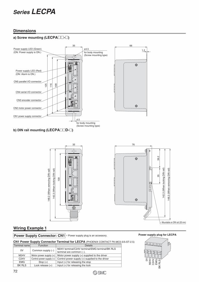
Dimensions
a) Screw mounting (LECPA - )
Wiring Example 1
Power Supply Connector: CN1
CN1 Power Supply Connector Terminal for LECPA (PHOENIX CONTACT FK-MC0.5/5-ST-2.5)Terminal name Function Details
0V
M24VC24VEMG
BK RLS
Common supply ( )
Motor power supply (+)Control power supply (+)
Stop (+)Lock release (+)
Motor power supply (+) supplied to the driverControl power supply (+) supplied to the driverInput (+) for releasing the stopInput (+) for releasing the lock
M24V terminal/C24V terminal/EMG terminal/BK RLS terminal are common ( ).
Power supply plug for LECPA
0VM
24V
C24
VE
MG
BK
RLS
Power supply plug is an accessory.
b) DIN rail mounting (LECPA D- )
35Power supply LED (Green)(ON: Power supply is ON.)
125
116
109
4.5for body mounting(Screw mounting type)
ø4.5for body mounting(Screw mounting type)
1.2
66
76
39.2
142.
3 (W
hen
lock
ing
DIN
rai
l)
148.
2 (W
hen
rem
ovin
g D
IN r
ail)
Mountable on DIN rail (35 mm)
35
Power supply LED (Red)(ON: Alarm is ON.)
CN5 parallel I/O connector
CN4 serial I/O connector
CN3 encoder connector
CN2 motor power connector
CN1 power supply connector
35
109
148.
2 (W
hen
rem
ovin
g D
IN r
ail)
142.
3 (W
hen
lock
ing
DIN
rai
l)
72
Series LECPA

COM+
COM
NP+
NP
PP+
PP
SETUP
RESET
SVON
CLR
TL
TLOUT
WAREA
BUSY
SETON
INP
SVRE
ESTOP Note 2)
ALARM Note 2)
AREA
Terminal name
CN5
1
2
3
4
5
6
7
8
9
10
11
12
13
14
15
16
17
18
19
20
Pin no.
FGRound terminal
0.5-5
24 V
0 V
Pulse signal
Pulse signal
Pulse signal
Pulse signal
Input
Input
Input
Input
Input
Output
Output
Output
Output
Output
Output
Output
Output
Output
Function
Power supply24 VDC 10%for I/O signal
Note 1)
Note 1) For pulse signal wiring method, refer to “Pulse Signal Wiring Details”.Note 2) Output when the power supply of the driver is ON. (N.C.)
Pulse signal output of positioning unit is differential output
Pulse signal output of positioning unit is open collector output
Current limitresistor R Note)
Current limitresistor R Note)
Pulse signal power supply
Positioning unit
Positioning unit
Inside of the driver
120
120
120
120
1 k
1 k
NP+
NP
PP+
PP
Inside of the driver
NP+
NP
PP+
PP
FGRound terminal
0.5-5
Power supply24 VDC 10%for I/O signal
Note 1)
COM+
COM
NP+
NP
PP+
PP
SETUP
RESET
SVON
CLR
TL
TLOUT
WAREA
BUSY
SETON
INP
SVRE
ESTOP Note 2)
ALARM Note 2)
AREA
Terminal name
CN5
1
2
3
4
5
6
7
8
9
10
11
12
13
14
15
16
17
18
19
20
Pin no.
24 V
0 V
Pulse signal
Pulse signal
Pulse signal
Pulse signal
Input
Input
Input
Input
Input
Output
Output
Output
Output
Output
Output
Output
Output
Output
Function
1 k
1 k
Load
Load
Load
Load
Load
Load
Load
Load
Load
Load
Load
Load
Load
Load
Load
Load
Load
Load
Wiring Example 2
Pulse Signal Wiring Details
LECPAN - (NPN) LECPAP - (PNP)
Input SignalNameCOM+COMSETUPRESETSVONCLRTL
DetailsConnects the power supply 24 V for input/output signalConnects the power supply 0 V for input/output signal
Instruction to return to originAlarm reset
Servo ON instructionDeviation reset
Instruction to pushing operation
Pulse signal power supply voltage24 VDC 10%
5 VDC 5%
Current limit resistor R specifications3.3 k 5% (0.5 W or more)390 5% (0.1 W or more)
Output SignalNameBUSY
SETONINP
SVREESTOP Note 3)
ALARM Note 3)
AREAWAREATLOUT
DetailsOutputs when the actuator is operating
Outputs when returning to originOutputs when target position is reached
Outputs when servo is onNot output when EMG stop is instructed
Not output when alarm is generatedOutputs within the area output setting rangeOutputs within W-AREA output setting range
Outputs during pushing operation
Note) Connect the current limit resistor R in series to correspond to the pulse signal voltage.
Note 3) Signal of negative-logic circuit ON (N.C.)
Parallel I/O Connector: CN5 When you connect a PLC, etc., to the CN5 parallel I/O connector, please use the I/O cable (LEC-CL5- ). The wiring should be changed depending on the type of the parallel I/O (NPN or PNP).
73
Step Motor Driver Series LECPA
LE
YL
EC
SL
EC
A6
LE
CP
6L
EC
-GL
EC
P1
LE
CP
AL
EY
GL
EY
LE
YG
Mod
elS
elec
tion
Ser
vo M
otor
(24
VD
C)/S
tep
Mot
or (S
ervo
/24
VD
C)
AC
Ser
vo M
otor
Spec
ific P
rodu
ctPr
ecau
tions

Power supply
SVON
SETUP
BUSY
SVRE
SETON
INP
ALARM
ESTOP
Input
Output
Speed
Return to origin
24 V0 V
ONOFF
0 mm/s
ONOFF
If the actuator is within the “in position” range of the basic parameter, INP will turn ON, but if not, it will remain OFF.
“ ALARM” and “ ESTOP” are expressed as negative-logic circuit.
Pulse signal
BUSY
INP
SpeedPositioning operation
ONOFF
0 mm/s
ONOFF
TL
TLOUT
BUSY
INP
Pulse signal
SpeedPushing operation
ONOFF
0 mm/s
ONOFF
Note) If pushing operation is stopped when there is no pulse deviation, the moving part of the actuator may pulsate.
“ ALARM” is expressed as negative-logic circuit.
RESET
ALARM
Input
Output
ONOFF
ONOFF
Alarm out
Alarm reset
Signal Timing
Return to Origin
Input
Output
If the actuator is within the “in position” range of the step data, INP will turn ON, but if not, it will remain OFF.
If the current pushing force exceeds the “trigger LV” value of the step data, INP signal will turn ON.
Input
Output
Alarm Reset
Positioning Operation Pushing Operation
74
Series LECPA

(17.
7)(1
7.7)
(30.7)Connector A
L (11)
(30.7) L (11)
(14.2) (Terminal no.)
(14)
(18)
(14.2)
(14)
(18)
A1 B1
A6 B6
1 25 6
1 2
15 16
(ø8)(Terminal no.)
Connector C
Connector A
(ø5.
5)(ø
6.3)
(Terminal no.)
1 25 6
1 2
15 16
Driver side
A1 B1
A6 B6
(Terminal no.)
Actuator side
Actuator side
Driver side
(13.5)
(10)Connector D
Connector C
Connector D(14.7)
(13.5)
(10)
(14.7)
B1(Terminal no.)
B6
A1
A6B1B3
A1A3
B1(Terminal no.)
B6
A1
A6
B1B3
A1A3
(ø8)
(ø5.
7)
(17.
7)(1
0.2)
(30.7) L (11)
(14.2)
(14)
(18)
(ø5.
5)
(ø6.
3)(ø
5.7)
(17.
7)(1
0.2)
(30.7) L (11)
(14.2)
(14)
(18)
Actuator side Driver side
Actuator sideDriver side
(Terminal no.)
(Terminal no.)
Connector A
Connector B
Connector A
Connector B
Connector C
Connector D
Connector C
Connector D
(14.7)
(14.7)
1 25 6
1 2
15 16
(13.5)
(10)
1 25 6
1 2
15 16
(13.5)
(10)
Options: Actuator Cable
[Robotic cable, standard cable for step motor (Servo/24 VDC)]
LE CP 1
Cable length (L) [m]1358ABC
1.5358
101520
Connector Aterminal no.
B-1A-1B-2A-2B-3A-3
AABB
COM-A/COMCOM-B/—
B-4A-4B-5A-5B-6A-6
VccGND
AABB
Signal Cable color
BrownRed
OrangeYellowGreenBlue
BrownBlackRed
BlackOrangeBlack
—
Connector Cterminal no.
Cable color Connector Dterminal no.
216534
121376983
LE-CP- /Cable length: 1.5 m, 3 m, 5 m135
LE-CP- /Cable length: 8 m, 10 m, 15 m, 20 m( Produced upon receipt of order)
8A
BC
Produced upon receipt of order (Robotic cable only)
Cable type
Shield
Connector Aterminal no.
B-1A-1B-2A-2B-3A-3
AABB
COM-A/COMCOM-B/—
B-1A-1B-3A-3
Lock (+)Lock ( )
Sensor (+) Note)
Sensor ( ) Note)
B-4A-4B-5A-5B-6A-6
VccGND
AABB
Signal
Connector Bterminal no.Signal
Cable color
BrownRed
OrangeYellowGreenBlue
BrownBlackRed
BlackOrangeBlack
—
Connector Cterminal no.
Cable color Connector Dterminal no.
216534
121376983
RedBlackBrownBlue
4512
Shield
[Robotic cable, standard cable with lock and sensor for step motor (Servo/24 VDC)]
LE-CP- /Cable length: 1.5 m, 3 m, 5 m135
LE-CP- /Cable length: 8 m, 10 m, 15 m, 20 m( Produced upon receipt of order)
8A
BC
LE CP 1 B
Cable length (L) [m]
With lock and sensor
1358ABC
1.5358
101520
Produced upon receipt of order (Robotic cable only)
Note) Not used for the LE series.
Nil
S
Robotic cable(Flexible cable)
Standard cable
Cable type
Nil
S
Robotic cable(Flexible cable)
Standard cable
75
Step Motor Driver Series LECPA
LE
YL
EC
SL
EC
A6
LE
CP
6L
EC
-GL
EC
P1
LE
CP
AL
EY
GL
EY
LE
YG
Mod
elS
elec
tion
Ser
vo M
otor
(24
VD
C)/S
tep
Mot
or (S
ervo
/24
VD
C)
AC
Ser
vo M
otor
Spec
ific P
rodu
ctPr
ecau
tions

(42.2) (28.8)
(33.
5)
(12.
5)
1
19
2
20(12)
L
(40)(10)
(45)
100 10
(22)
(25)
Options
LEC CI/O cable length (L)
135
1.5 m3 m5 m
I/O cable typeL5 For LECPA
1L5[I/O cable]
Pinno.
Insulationcolor
Dotmark
Dotcolor
1234567891011
Light brownLight brown
YellowYellow
Light greenLight green
GrayGrayWhiteWhite
Light brown
BlackRed
BlackRed
BlackRed
BlackRed
BlackRed
Black
Pinno.
Round terminal0.5-5
Insulationcolor
Dotmark
Green
Dotcolor
121314151617181920
Light brownYellowYellow
Light greenLight green
GrayGrayWhiteWhite
RedBlackRed
BlackRed
BlackRed
BlackRed
LEC NFA
Refer to the LECPA series Operation Manual for installation.
Contents of the set: 2 noise filters (Manufactured by WURTH ELEKTRONIK: 74271222)
[Noise filter set]Step Motor Driver (Pulse Input Type)
Pulse input usable only with differential. Only 1.5 m cables usable with open collector.
Number of coresAWG size
2024
76
Series LECPA

HRS
PC
Controller setting software
Communication cable
USB cable (A-miniB type)
How to Order
Contents
Controller setting software (CD-ROM)
Communication cable
USB cable (Cable between the PC and the conversion unit)
LEC W2Controller setting kit
(Japanese and English are available.)
Series LECController Setting Kit/LEC-W2
Screen Example
Easy mode screen example
Compatible Controllers/Driver
Step motor controller (Servo/24 VDC) Series LECP6Servo motor controller (24 VDC) Series LECA6Step motor driver (Pulse input type) Series LECPA
Hardware Requirements
Display
Communication interface
OS
XGA (1024 x 768) or more
USB 1.1 or USB 2.0 ports
IBM PC/AT compatible machine runningWindows®XP (32-bit),Windows®7 (32-bit and 64-bit).
Windows® and Windows®7 are registered trademarks of Microsoft Corporation in the United States. Refer to SMC website for version update information, http://www.smcworld.com
Easy operation and simple settingAllowing to set and display actuator step data such as position, speed, force, etc.Setting of step data and testing of the drive can be performed on the same page.Can be used to jog and move at a constant rate.
Normal mode screen example
Detailed settingStep data can be set in detail.Signals and terminal status can be monitored.Parameters can be set.JOG and constant rate movement, return to origin, test operation and testing of forced output can be performed.
77
Windows®XP, Windows®7 compatible
LE
YL
EC
SL
EC
A6
LE
CP
6L
EC
-GL
EC
P1
LE
CP
AL
EY
GL
EY
LE
YG
Mod
elS
elec
tion
Ser
vo M
otor
(24
VD
C)/S
tep
Mot
or (S
ervo
/24
VD
C)
AC
Ser
vo M
otor
Spec
ific P
rodu
ctPr
ecau
tions

How to Order
Specifications
LEC T1 3 J GEnable switch
SNone
Equipped with enable switchNil
Teaching box
Cable length [m]
Stop switchG Equipped with stop switch
Initial language
Item
Switch
Cable length [m]
Enclosure
Operating temperature range [ C]
Operating humidity range [%RH]
Weight [g]
Stop switch, Enable switch (Option)
3
IP64 (Except connector)
5 to 50
90 or less (No condensation)
350 (Except cable)
Description
Easy Mode
Standard functions Chinese character display Stop switch is provided.
Option Enable switch is provided.
Function
Step data
Jog
Test
Monitor
ALM
TB setting
Details
Jog operation Return to origin
Setting of step data
1 step operation Note 1)
Return to origin
Display of axis and step data no. Display of two items selected from Position, Speed, Force.
Active alarm display Alarm reset
Reconnection of axis (Ver. 1. ) Displayed language setting(Ver. 2. )
Setting of easy/normal mode Setting step data and selection of items from easy mode monitor
MenuDataMonitorJogTestALMTB setting
JogReturn to originJog operation
Test Note 1)
1 step operation
ALMActive alarm displayAlarm reset
TB settingReconnection of axis (Ver. 1. )Japanese/English (Ver. 2. )Easy/NormalSet item
DataStep data no.Setting of two items selected belowVer. 1. :Position, Speed, Force, Acceleration, DecelerationVer. 2. :Position, Speed, Pushing force, Acceleration, Deceleration, Movement MOD, Trigger LV, Pushing speed, Moving force, Area 1, Area 2, In position
MonitorDisplay of step no.Display of two items selected below(Position, Speed, Force)
Menu Operations Flowchart
Interlock switch for jog and test function
Enable switch(Option)
Stop switch
[CE-compliant products]The EMC compliance of the teaching box was tested with the LECP6 series step motor controller (servo/24 VDC) and an applicable actuator.[UL-compliant products]When conformity to UL is required, the electric actuator and driver should be used with a UL1310 Class 2 power supply.
Series LECTeaching Box/LEC-T1
®
RoHS
Note 1) Not compatible with the LECPA.
3 3
JE
JapaneseEnglish
The displayed language can be changed to English or Japanese.
78

185
1024
25 22.5
34.5
Normal Mode
Dimensions
No.
1
2
3
4
5
6
7
8
LCD
Ring
Stop switch
Stop switch guard
Enable switch(Option)
Key switch
Cable
Connector
A screen of liquid crystal display (with backlight)
A ring for hanging the teaching box
A guard for the stop switch
Switch for each input
Length: 3 meters
A connector connected to CN4 of the driver
When switch is pushed in, the switch locks and stops.The lock is released when it is turned to the right.
FunctionDescription
Prevents unintentional operation (unexpected operation) of the jog test function.Other functions such as data change are not covered.
Function
Step data
Parameter
Test
Monitor
ALM
File
TB setting
Reconnect
Details
Step data setting
Parameters setting
Jog operation/Constant rate movementReturn to originTest drive Note 1)
(Specify a maximum of 5 step data and operate.)Forced output(Forced signal output, Forced terminal output) Note 2)
Drive monitorOutput signal monitor Note 2)
Input signal monitor Note 2)
Output terminal monitorInput terminal monitor
Active alarm display(Alarm reset)Alarm log record display
Data savingSave the step data and parameters of the driver which is being used for communication (it is possible to save four files, with one set of step data and parameters defined as one file).Load to driverLoads the data which is saved in the teaching box to the driver which is being used for communication.Delete the saved data.
File protection (Ver. 2. )
Display setting(Easy/Normal mode)
Language setting (Japanese/English)
Backlight setting LCD contrast setting Beep sound setting Max. connection axis Distance unit (mm/inch)
Reconnection of axis
MenuStep dataParameterMonitorTestALMFileTB settingReconnect
Step dataStep data no.Movement MODSpeedPositionAccelerationDecelerationPushing forceTrigger LVPushing speedMoving forceArea 1, 2In position
ParameterBasicORIG
DRV monitorPosition, Speed, TorqueStep no.Last step no.
StatusActive alarm displayAlarm reset
ALM Log record displayLog entry display
MonitorDriveOutput signal Note 2)
Input signal Note 2)
Output terminalInput terminal
TestJOG/MOVEReturn to ORIGTest drive Note 1)
Forced output Note 2)
ALMStatusALM Log record
TB settingEasy/NormalLanguageBacklightLCD contrastBeepMax. connection axisPasswordDistance unit
Reconnect
Basic setting
ORIG setting
Output signal monitor
Input signal monitor
Output terminal monitor
Input terminal monitor
FileData savingLoad to driverFile deletionFile protection (Ver. 2. )
Menu Operations Flowchart
Note 1) Not compatible with the LECPA.
Note 2) The following signals are not compatible with the LECPA.Input: CLR, TLOutput: TLOUT
79
Teaching Box Series LEC
LE
YL
EC
SL
EC
A6
LE
CP
6L
EC
-GL
EC
P1
LE
CP
AL
EY
GL
EY
LE
YG
Mod
elS
elec
tion
Ser
vo M
otor
(24
VD
C)/S
tep
Mot
or (S
ervo
/24
VD
C)
AC
Ser
vo M
otor
Spec
ific P
rodu
ctPr
ecau
tions

80

AC Servo Motor
Series LEYRod Type
Series LECSAC Servo Motor Driver
Series LEYGGuide Rod Type
Motor top mounting type
In-line motor type
Motor top/parallel type
In-line motor type
Page 82
Page 106
Page 119
e Page 106
In-line motor type
Motor top mounting type
Series LEY-X5Dust/Drip proof (IP65) specification Page 101
81
LE
YL
EC
SL
EC
A6
LE
CP
6L
EC
-GL
EC
P1
LE
CP
AL
EY
GL
EY
LE
YG
Spec
ific P
rodu
ctPr
ecau
tions
AC
Ser
vo M
otor
Ser
vo M
otor
(24
VD
C)/S
tep
Mot
or (S
ervo
/24
VD
C)
Mod
elS
elec
tion

T1
a1 a2
L
Spe
ed: V
[mm
/s]
Time [s]
T2 T3 T4
0
5
10
15
20
25
30
35
40
0 200 400 600 800 1000 1200Speed [mm/s]
Wor
k lo
ad [k
g]
Lead 12: LEY25 A
Lead 6: LEY25 B
Lead 3: LEY25 C
Step 1 Check the work load–speed. <Speed–Vertical work load graph>
Step 2 Check the cycle time.
Workpiece mass: 16 [kg] Speed: 300 [mm/s]
Acceleration/Deceleration: 5,000 [mm/s2]
Stroke: 300 [mm]
Workpiece mounting condition: Vertical upward downward transfer
Operatingconditions
Selection Procedure
Positioning Control Selection Procedure
Selection Example
Step 1Check the work load–speed.(Vertical transfer) Step 2 Check the cycle time.
Calculate the cycle time using the following calculation method.
Cycle time T can be found from the following equation.
Select the target model based on the workpiece mass and speed with reference to the <Speed–Vertical work load graph>.
Selection example) The LEY25 B is temporarily selected based on the graph shown on the right side.
T = T1 + T2 + T3 + T4 [s]
T1 = V/a1 [s]
T4 = 0.05 [s]
T3 = V/a2 [s]
T2 = [s]L – 0.5 V (T1 + T3)
V
T4: Settling time varies depending on the conditions such as motor types, load and in positioning of the step data. Therefore, please calculate the settling time with reference to the following value.
T2: Constant speed time can be found from the following equation.
T1: Acceleration time and T3: Deceleration time can be obtained by the following equation.
L : Stroke [mm] (Operating condition)V : Speed [mm/s] (Operating condition)a1: Acceleration [mm/s2] (Operating condition)a2: Deceleration [mm/s2] (Operating condition)
T1: Acceleration time [s] Time until reaching the set speedT2: Constant speed time [s] Time while the actuator is
operating at a constant speedT3: Deceleration time [s] Time from the beginning of the
constant speed operation to stopT4: Settling time [s] Time until in position is completedCalculation example)
T1 to T4 can be calculated as follows.
T1 = V/a1 = 300/5000 = 0.06 [s], T3 = V/a2 = 300/5000 = 0.06 [s]
T4 = 0.05 [s]
Therefore, the cycle time can be obtained as follows.T = T1 + T2 + T3 + T4 = 0.06 + 0.94 + 0.06 + 0.05 = 1.11 [s]
T2 = = = 0.94 [s] L 0.5 V (T1 + T3)
V
300 0.5 300 (0.06 + 0.06)
300
W
<Speed–Vertical work load graph>(LEY25 )
It is necessary to mount a guide outside the actuator when used for horizontal transfer.When selecting the target model, refer to pages 90, 97 and 102 for the horizontal work load in the specifications, and page 117 for the precautions.
Based on the above calculation result, the LEY25 B-300 is selected.
Electric Actuator/Rod Type
Series LEY/LEY-X5Model Selection
The regeneration option may be necessary. Refer to pages 84, 85 and 87 for “Required Conditions for Regeneration Option”.
AC Servo Motor
25, 32Size Dust/Drip proof (IP65) specification
82

Load
: F [N
]
Stroke [mm]0 100 200 300 400 500 600
100
10
1
For
ce [N
]Torque limit/Command value [%]
500
400
300
200
100
02010 4030
Lead 3: LEY25 C
Lead 6: LEY25 B
Lead 12: LEY25 A
<Graph of allowable lateral load on the rod end>
Step 1 Check the pushing force. <Force conversion graph>
Mounting condition: Horizontal (pushing) Speed: 100 [mm/s]
Jig weight: 0.5 [kg] Stroke: 300 [mm]
Pushing force: 200 [N]
Operatingconditions
Pushing Control Selection Procedure
Selection Example
Check the lateral load on the rod end.
Step 1 Check the pushing force.
Select the target model based on the torque limit/command value and pushing force with reference to the <Force conversion graph>.
Selection example)Based on the graph shown on the right side,
Torque limit/Command value: 24 [%]Pushing force: 200 [N]
Therefore, the LEY25B is temporarily selected.
Step 2 Check the lateral load on the rod end. <Graph of allowable lateral load on the rod end>Confirm the allowable lateral load on the rod end of the actuator: LEY25B, which has been selected temporarily with reference to the <Graph of allowable lateral load on the rod end>.
Selection example)Based on the graph shown on the right side,
Jig weight: 0.2 [kg] 2 [N]Product stroke: 200 [mm]
Therefore, the lateral load on the rod end is in the allowable range.
Step 2
Jig
<Force conversion graph>(LEY25 )
LEY32
LEY25
Based on the above calculation result, the LEY25B-300 is selected.
Selection Procedure
83
Model Selection Series LEY/LEY-X525, 32Size Dust/Drip proof (IP65) specification
LE
YL
EC
SL
EC
A6
LE
CP
6L
EC
-GL
EC
P1
LE
CP
AL
EY
GL
EY
LE
YG
Spec
ific P
rodu
ctPr
ecau
tions
AC
Ser
vo M
otor
Mod
elS
elec
tion
Ser
vo M
otor
(24
VD
C)/S
tep
Mot
or (S
ervo
/24
VD
C)

0
10
20
30
40
16
8
37
19
9
0 200 400 600 800 1000 14001200
0 200 400 600 800 1000 14001200 0 200 400 600 800 1000 14001200
Speed [mm/s]
Wor
k lo
ad [k
g]
0
10
20
30
40
50
Speed [mm/s]
Wor
k lo
ad [k
g]
0
10
20
30
40
50
60
Speed [mm/s]
Wor
k lo
ad [k
g]
Lead 6: LEY25 B
Lead 3: LEY25 C
Lead 12: LEY25 A
Lead 20: LEY32 A
Lead 5: LEY32 C
Lead 10: LEY32 B
Lead 4: LEY32D C
Lead 8: LEY32D B
Lead 16: LEY32D A12
24
46
A
A
B
A
B
Speed–Vertical Work Load Graph/Required Conditions for “Regeneration Option”
Required conditions for “Regeneration option”LEY25 (Motor mounting position: Top/Parallel, In-line)
LEY32 (Motor mounting position: Top/Parallel) LEY32D (Motor mounting position: In-line)
Regeneration option required when using product above “Regeneration” line in graph. (Order separately)
Regenerative conditions
Duty ratio 50% or more
Duty ratio 100%
Operating conditions
A
B
Vertical transfer
LEC-MR-RB032
“Regeneration Option” Models
84
Series LEY/LEY-X525, 32Size Dust/Drip proof (IP65) specification

0 200 400 600 800 1000 14001200
0 200 400 600 800 1000 14001200 0 200 400 600 800 1000 14001200
Speed [mm/s]
Wor
k lo
ad [k
g]
Speed [mm/s]
Wor
k lo
ad [k
g]
Speed [mm/s]
Wor
k lo
ad [k
g]
0
10
20
30
40
50
60
70
Lead 6: LEY25 B
Lead 3: LEY25 C
Lead 12: LEY25 A
0
10
20
30
40
50
60
70
80
0
10
20
30
40
50
60
70
80
Lead 20: LEY32 A
Lead 5: LEY32 C
Lead 10: LEY32 B
Lead 4: LEY32D C
Lead 8: LEY32D B
Lead 16: LEY32D A
B B
A
A
Allowable Stroke Speed
Model AC servomotor
Lead Stroke [mm]
(Motor rotation speed)
(Motor rotation speed)
(Motor rotation speed)
Symbol [mm]
LEY25Motor mounting position:Top/Parallel, In-line
100 W/ 40
ABC
ABC
ABC
1263
20105
1684
900450225
(4500 rpm)
600300150
(3000 rpm)
————
————
1200600300
(3600 rpm)1000500250
(3750 rpm)
800400200
(2400 rpm)640320160
(2400 rpm)
[mm/s]
LEY32Motor mounting position:
Top/Parallel
200 W/ 60
LEY32DMotor mounting position:
In-line
200 W/ 60
30 50 100 150 200 250 300 350 400 450 500
Speed–Horizontal Work Load Graph/Required Conditions for “Regeneration Option”
Required conditions for “Regeneration option”LEY25 (Motor mounting position: Top/Parallel, In-line)
LEY32 (Motor mounting position: Top/Parallel) LEY32D (Motor mounting position: In-line)
Regeneration option required when using product above “Regeneration” line in graph. (Order separately)
Regenerative conditions
Duty ratio 50% or more
Duty ratio 100%
Operating conditions
A
B
Horizontal transfer
LEC-MR-RB032
“Regeneration Option” Models
85
Model Selection Series LEY/LEY-X525, 32Size Dust/Drip proof (IP65) specification
LE
YL
EC
SL
EC
A6
LE
CP
6L
EC
-GL
EC
P1
LE
CP
AL
EY
GL
EY
LE
YG
Spec
ific P
rodu
ctPr
ecau
tions
AC
Ser
vo M
otor
Mod
elS
elec
tion
Ser
vo M
otor
(24
VD
C)/S
tep
Mot
or (S
ervo
/24
VD
C)

Load
: F [N
]
Stroke [mm]
100
10
10 300200 400100 500 600
LEY32
LEY25
For
ce [N
]
Torque limit/Command value [%]
500
400
300
200
100
02010 4030
For
ce [N
]
Torque limit/Command value [%]
800
700
600
500
400
300
200
100
02010 4030
For
ce [N
]
Torque limit/Command value [%]
600
500
400
300
200
100
02010 4030
Lead 3: LEY25 C
Lead 5: LEY32 C
Lead 10: LEY32 B
Lead 20: LEY32 A
Lead 6: LEY25 B
Lead 12: LEY25 A
Lead 4: LEY32D C
Lead 8: LEY32D B
Lead 16: LEY32D A
Force Conversion Graph (Guide)
Graph of Allowable Lateral Load on the Rod End (Guide)
F
Center of gravity
[Stroke] = [Product stroke] + [Distance from the rod end to the center of gravity of the workpiece]
Workpiece
LEY25 (Motor mounting position: Top/Parallel, In-line)
LEY32D (Motor mounting position: In-line)LEY32 (Motor mounting position: Top/Parallel)
1 Motor type: When limiting torque with incremental encoder, parameter No. PC12/the value of the internal torque command should be set 30% or less.2 Motor type: When limiting torque with absolute encoder, parameter No. PC13/the value of the maximum output command for analog torque should be set
30% or less.
86
Series LEY/LEY-X525, 32Size Dust/Drip proof (IP65) specification

Speed–Work Load Graph/Required Conditions for “Regeneration Option”
Vertical transfer Horizontal transfer
Required conditions for “Regeneration option” Regeneration option required when using product above “Regeneration” line in graph. (Order separately)
Allowable Stroke Speed
Force Conversion Graph Graph of Allowable Lateral Load on the Rod End
Model
400 W/ 60
AC servomotor
ABC
20
10
5
Lead
(Motor rotation speed)
[mm]Symbol 100 200 300 400 500Stroke [mm]
[mm/s]
1000
500
250
(3000 rpm)
600800
400
200
(2400 rpm)
700600
300
150
(1800 rpm)
800500
250
125
(1500 rpm)
LEY63
LEY63 LEY63
Duty ratio [%]
100
100 (60)
50 (30)
30 (20)
Continuous pushing time [minute]
—
— (1.5)
1.5 (0.5)
0.5 (0.16)
Torque limit/Command value [%]
25 or less
30
40
50
1 The values in ( ) are for a closely-mounted driver.2 Motor type: When limiting torque with incremental encoder, parameter
No. PC12/the value of the internal torque command should be set 50% or less.
3 Motor type: When limiting torque with absolute encoder, parameter No. PC13/the value of the maximum output command for analog torque should be set 50% or less.
0
200
400
600
800
1000
1200
1400
1600
1800
2000
10 20 30 40 50 60
Torque limit/Command value [%]
For
ce [N
]
Lead 5: LEY63 C
Lead 10: LEY63 B
Lead 20: LEY63 A
F
Center of gravity
[Stroke] = [Product stroke] + [Distance from the rod end to the center of gravity of the workpiece]
1
10
100
0 100 200 300 400 500 600 700 800 900 1000
Stroke [mm]
Load
: F (
N)
LEY63
LEY63 (Motor mounting position: In-line)
0
20
40
60
80
100
0 200 400 600 800 1000 1200 1400
Speed [mm/s]
Wor
k lo
ad [k
g]
0
20
40
60
80
100
0 200 400 600 800 12001000
Speed [mm/s]
Wor
k lo
ad [k
g]
Lead 20:LEY63 A
Lead 10:LEY63 B
Lead 5:LEY63 C
Lead 20: LEY63 A
Lead 10: LEY63 BLead 5: LEY63 C
A
B
C
Regenerative conditions
Duty ratio 50% or more
Duty ratio 100%
Operating conditions
ABC
Vertical transfer
LEC-MR-RB-032
LEC-MR-RB-12
Horizontal transfer
Not required
“Regeneration Option” Models
87
Model Selection Series LEY63Size Dust/Drip proof (IP65) specification
(Select options)
LE
YL
EC
SL
EC
A6
LE
CP
6L
EC
-GL
EC
P1
LE
CP
AL
EY
GL
EY
LE
YG
Spec
ific P
rodu
ctPr
ecau
tions
AC
Ser
vo M
otor
Mod
elS
elec
tion
Ser
vo M
otor
(24
VD
C)/S
tep
Mot
or (S
ervo
/24
VD
C)

How to Order
LEY25, 32Series LEY
LEY 25 100B 2 A1
2532
Applicable stroke table
LEY25LEY32
Stroke(mm)Model
30 50 100 150 200 250 300 350 400
—
450
—
500
S
15 to 40020 to 500
Manufacturablestroke range
Note) Consult with SMC for non-standard strokes as they are produced as special orders.
Size
30to
500 Refer to the table below for details.
30to
500
Stroke [mm]
When “With lock” is selected for the top mounting and right/left side parallel types, the motor body will stick out of the end of the body for size 25 with strokes 30 or less. Check for interference with workpieces before selecting a model.
NilB
Without optionWith lock
Motor option
Nil
M
Rod end female thread
Rod end male thread(1 rod end nut is included.)
Rod end thread
NilRLD
Top mountingRight side parallelLeft side parallel
In-line
Motor mounting position
1 Mounting bracket is shipped together, (but not assembled).
2 For horizontal cantilever mounting with the rod flange, head flange and ends tapped, use the actuator within the following stroke range.LEY25: 200 or less LEY32: 100 or less
3 For mounting with the double clevis, use the actuator within the following stroke range.LEY25: 200 or less LEY32: 200 or less
4 Head flange is not available for the LEY32.
S2
The values shown in ( ) are the lead for size 32 top mounting, right/left side parallel types.(Equivalent lead which includes the pulley ratio [1.25:1])
ABC
LEY251263
LEY3216 (20)8 (10)4 (5)
Symbol
Lead [mm]
Electric Actuator/Rod Type
25, 32Size
NilULFGD
Ends tapped (Standard) 2
Body bottom tappedFoot
Rod flange 2
Head flange 2
Double clevis 3
Motor mounting positionTypeSymbol
Top/Parallel
4
In-line
—
——
Mounting 1
For auto switches, refer to pages 20 and 21.
S2
S3
100
200
25
32
S6
S7
100
200
25
32
Symbol Type Actuatorsize
Output[W]
AC servo motor(Incremental encoder)
AC servo motor(Incremental encoder)
AC servo motor(Absolute encoder)
AC servo motor(Absolute encoder)
LECSA -S1
LECSA -S3
LECSB -S5LECSC -S5LECSS -S5
LECSB -S7LECSC -S7LECSS -S7
Compatibledrivers 2
Motor type 1
1: For motor type S2 and S6, the compatible driver part number suffixes are S1 and S5 respectively.
2: For details about the driver, refer to page 120.
RoHS
AC Servo Motor
Standard
Motor
88
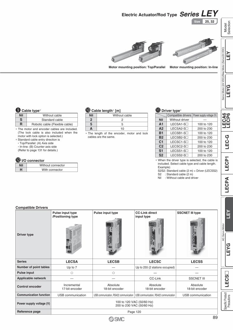
Motor mounting position: Top/Parallel Motor mounting position: In-line
NilSR
Without cableStandard cable
Robotic cable (Flexible cable)
The motor and encoder cables are included. (The lock cable is also included when the motor with lock option is selected.)
Standard cable entry direction is Top/Parallel: (A) Axis side In-line: (B) Counter axis side
(Refer to page 131 for details.)
Cable typeNil25A
Without cable2510
Cable length [m]
NilH
Without connectorWith connector
I/O connector
Compatible Drivers
Driver type
LECSA
Up to 7
—
USB communication
LECSB
—
—
USB communication, RS422 communication
Page 120
100 to 120 VAC (50/60 Hz)200 to 230 VAC (50/60 Hz)
Pulse input type/Positioning type
Pulse input type
LECSC
Up to 255 (2 stations occupied)
—
CC-Link
USB communication, RS422 communication
CC-Link directinput type
LECSS
—
—
SSCNET III
USB communication
SSCNET III type
Series
Number of point tables
Pulse input
Applicable network
Control encoder
Communication function
Power supply voltage (V)
Reference page
Incremental17-bit encoder
Absolute18-bit encoder
Absolute18-bit encoder
Absolute18-bit encoder
Driver type
NilA1A2B1B2C1C2S1S2
Without driverLECSA1-SLECSA2-SLECSB1-SLECSB2-SLECSC1-SLECSC2-SLECSS1-SLECSS2-S
—100 to 120200 to 230100 to 120200 to 230100 to 120200 to 230100 to 120200 to 230
Power supply voltage (V)Compatible drivers
When the driver type is selected, the cable is included. Select cable type and cable length.Example)S2S2: Standard cable (2 m) + Driver (LECSS2)S2 : Standard cable (2 m)Nil : Without cable and driver
The length of the encoder, motor and lock cables are the same.
89
Electric Actuator/Rod Type Series LEY25, 32Size
LE
YL
EC
SL
EC
A6
LE
CP
6L
EC
-GL
EC
P1
LE
CP
AL
EY
GL
EY
LE
YG
Mod
elS
elec
tion
Ser
vo M
otor
(24
VD
C)/S
tep
Mot
or (S
ervo
/24
VD
C)
AC
Ser
vo M
otor
Spec
ific P
rodu
ctPr
ecau
tions
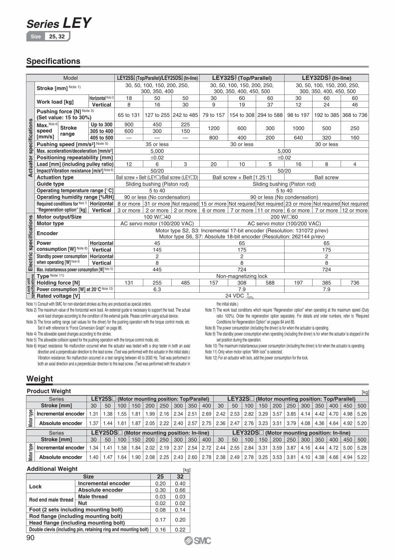
Specifications
Weight
Model
188
65 to 131
900600—
5016
127 to 255
450300—
35 or less
5030
242 to 485
225150—
309
79 to 157
1200
800
6019
154 to 308
600
40030 or less
6037
294 to 588
300
200
3012
98 to 197
1000
640
6024
192 to 385
500
32030 or less
6046
368 to 736
250
160
30, 50, 100, 150, 200, 250,300, 350, 400
30, 50, 100, 150, 200, 250,300, 350, 400, 450, 500
30, 50, 100, 150, 200, 250,300, 350, 400, 450, 500
LEY25S26 (Top/Parallel)/LEY25DS2
6 (In-line) LEY32S37 (Top/Parallel) LEY32DS3
7 (In-line)
Stroke [mm] Note 1)
Pushing speed [mm/s2] Note 5)
Max. acceleration/deceleration [mm/s2]Positioning repeatability [mm]Lead [mm] (including pulley ratio)Impact/Vibration resistance [m/s2] Note 6)
Actuation typeGuide typeOperating temperature range [ C]Operating humidity range [%RH]
Motor output/SizeMotor type
Encoder
Max. instantaneous power consumption [W] Note 10)
Type Note 11)
Holding force [N]Power consumption [W] at 20 C Note 12)
Rated voltage [V]
Work load [kg]Horizontal Note 2)
Vertical
HorizontalVertical
Strokerange
Up to 300305 to 400405 to 500
12 6
Ball screw + Belt (LEY )/Ball screw (LEY D)
31 or more2 or more
100 W/ 40
3 20 10
Ball screw + Belt [1.25:1]
5 16
200 W/ 60
5,0000.02
50/20
Sliding bushing (Piston rod)5 to 40
90 or less (No condensation)
AC servo motor (100/200 VAC)
5,0000.02
50/20
Sliding bushing (Piston rod)5 to 40
90 or less (No condensation)
AC servo motor (100/200 VAC)
8
Ball screw
4
8 or more3 or more
Not required2 or more
15 or more6 or more
Not required7 or more
Not required7 or more
Not required11 or more
23 or more6 or more
Not required12 or more
131 2556.3
485 157Non-magnetizing lock
3087.9
Motor type S2, S3: Incremental 17-bit encoder (Resolution: 131072 p/rev)Motor type S6, S7: Absolute 18-bit encoder (Resolution: 262144 p/rev)
24 VDC
588 197 3857.9
4514528
445
6517528
724
6517528
724
736
Act
uat
or
spec
ific
atio
ns
Ele
ctri
c sp
ecif
icat
ion
sLo
ck u
nit
spec
ifica
tions
Moto
r typ
eMo
tor t
ype
HorizontalVertical
HorizontalVertical
010%
Series
Incremental encoder
Absolute encoder
LEY25S (Motor mounting position: Top/Parallel) LEY32S (Motor mounting position: Top/Parallel)Stroke [mm] 30 50 100 150 200 250 300 350 400 30 50 100 150 200 250 300 350 400 450 500
Series
Incremental encoder
Absolute encoder
LEY25DS (Motor mounting position: In-line) LEY32DS (Motor mounting position: In-line)Stroke [mm] 30 50 100 150 200 250 300 350 400 30 50 100 150 200 250 300 350 400 450 500
Pushing force [N] Note 3)
(Set value: 15 to 30%)
Required conditions for Note 7)
“Regeneration option” [kg]
Note 4)Max. speed[mm/s]
[kg]Product Weight
Size 25 32
Lock
Rod end male thread
Foot (2 sets including mounting bolt)Rod flange (including mounting bolt)Head flange (including mounting bolt)Double clevis (including pin, retaining ring and mounting bolt)
Incremental encoderAbsolute encoderMale threadNut
0.200.300.030.020.08
0.17
0.16
0.400.660.030.020.14
0.20
0.22
[kg]Additional Weight
Powerconsumption [W] Note 8)
Standby power consumptionwhen operating [W] Note 9)
1.34
1.40
1.41
1.47
1.58
1.64
1.84
1.90
2.02
2.08
2.19
2.25
2.37
2.43
2.54
2.60
2.72
2.78
2.44
2.38
2.55
2.49
2.84
2.78
3.31
3.25
3.59
3.53
3.87
3.81
4.16
4.10
4.44
4.38
4.72
4.66
5.00
4.94
5.28
5.22
1.31
1.37
1.38
1.44
1.55
1.61
1.81
1.87
1.99
2.05
2.16
2.22
2.34
2.40
2.51
2.57
2.69
2.75
2.42
2.36
2.53
2.47
2.82
2.76
3.29
3.23
3.57
3.51
3.85
3.79
4.14
4.08
4.42
4.36
4.70
4.64
4.98
4.92
5.26
5.20
Note 1) Consult with SMC for non-standard strokes as they are produced as special orders.Note 2) The maximum value of the horizontal work load. An external guide is necessary to support the load. The actual
work load changes according to the condition of the external guide. Please confirm using actual device.Note 3) The force setting range (set values for the driver) for the pushing operation with the torque control mode, etc.
Set it with reference to “Force Conversion Graph” on page 86.Note 4) The allowable speed changes according to the stroke.Note 5) The allowable collision speed for the pushing operation with the torque control mode, etc.Note 6) Impact resistance: No malfunction occurred when the actuator was tested with a drop tester in both an axial
direction and a perpendicular direction to the lead screw. (Test was performed with the actuator in the initial state.)Vibration resistance: No malfunction occurred in a test ranging between 45 to 2000 Hz. Test was performed in both an axial direction and a perpendicular direction to the lead screw. (Test was performed with the actuator in
the initial state.)Note 7) The work load conditions which require “Regeneration option” when operating at the maximum speed (Duty
ratio: 100%). Order the regeneration option separately. For details and order numbers, refer to “Required Conditions for Regeneration Option” on pages 84 and 85.
Note 8) The power consumption (including the driver) is for when the actuator is operating.Note 9) The standby power consumption when operating (including the driver) is for when the actuator is stopped in the
set position during the operation.Note 10) The maximum instantaneous power consumption (including the driver) is for when the actuator is operating.Note 11) Only when motor option “With lock” is selected.Note 12) For an actuator with lock, add the power consumption for the lock.
90
Series LEY25, 32Size

Construction
No. Description Material Note
1
2
3
4
5
6
7
8
9
10
11
12
13
14
15
16
17
18
19
Body
Ball screw (shaft)
Ball screw nut
Piston
Piston rod
Rod cover
Housing
Rotation stopper
Socket
Connected shaft
Bushing
Bumper
Bearing
Return box
Return plate
Magnet
Wear ring holder
Wear ring
Screw shaft pulley
Aluminum alloy
Alloy steel
Resin/Alloy steel
Aluminum alloy
Stainless steel
Aluminum alloy
Aluminum alloy
POM
Free cutting carbon steel
Free cutting carbon steel
Lead bronze cast
Urethane
—
Aluminum die-cast
Aluminum die-cast
—
Stainless steel
POM
Aluminum alloy
Anodized
Hard chrome anodized
Nickel plated
Nickel plated
Coating
Coating
Stroke 101 mm or more
Stroke 101 mm or more
No. Size
212532
Order no.
LE-D-2-2
LE-D-2-4
No. Description Material Note
20
21
22
23
24
25
26
27
28
29
30
31
32
Motor pulley
Belt
Bearing stopper
Parallel pin
Seal
Retaining ring
Motor adapter
Motor
Motor block
Hub
Spider
Socket (Male thread)
Nut
Aluminum alloy
—
Aluminum alloy
Stainless steel
NBR
Steel for spring
Aluminum alloy
—
Aluminum alloy
Aluminum alloy
Urethane
Free cutting carbon steel
Alloy steel
Phosphate coated
Coating
Coating
Nickel plated
Zinc chromated
Replacement Parts (Top/Parallel only)/Belt
Component Parts
A
A
B
B
A-A
Cable is shipped together.
B-B
Motor top mounting type: LEY2532
When rod end male thread selected
In-line motor type: LEY D2532
91
Electric Actuator/Rod Type Series LEY25, 32Size
LE
YL
EC
SL
EC
A6
LE
CP
6L
EC
-GL
EC
P1
LE
CP
AL
EY
GL
EY
LE
YG
Mod
elS
elec
tion
Ser
vo M
otor
(24
VD
C)/S
tep
Mot
or (S
ervo
/24
VD
C)
AC
Ser
vo M
otor
Spec
ific P
rodu
ctPr
ecau
tions

T2
US
1
US
1
T2
Dimensions: Motor Top/Parallel
Motor left side parallel type: LEY L2532 Motor right side parallel type: LEY R25
32
Stroke range(mm)
15 to 100
105 to 400
20 to 100
105 to 500
130.5
155.5
148.5
178.5
116
141
130
160
13
13
Size
[mm]
25
32
A B C
20
25
D
44
51
EH
45.5
56.5
EV
M8 x 1.25
M8 x 1.25
H
24
31
J
17
22
K
14.5
18.5
L
34
40
M O1
8
10
R
46
60
S
M5 x 0.8
M6 x 1.0
Size
25
32
92
118
T
1
1
U
40
60
V
26.5
34
Y
47
61
91
117
Size
2532
S1 T2
1
1
U
[mm]
Note) When the motor is mounted on the left or right side in parallel, the groove for auto switch on the side to which the motor is mounted is hidden.
Note 1) Range within which the rod can move. Make sure a workpiece mounted on the rod does not interfere with the workpieces and facilities around the rod.
Note 2) The direction of rod end width across flats ( K) differs depending on the products.
Rod operating range Note 1)
(Stroke + 4 mm)
Encoder Z phase detecting position
M
2 1
VE
V
J
K Note2)
EH
M
W
MY UM
TZ
S
X
L
Hthread depth C
B + Stroke
A + Stroke
4 x O1
thread depth R
øD
Stroke range(mm)
15 to 100
105 to 400
20 to 100
105 to 500
87
88.2
120
128.2
123.9
116.8
156.9
156.8
82.4
76.6
115.4
116.6
123.5
116.1
156.5
156.1
Without lock With lock Without lock
Incremental encoder Absolute encoder
With lock
W
14.1
17.1
Z
14.1
17.1
Z
15.8
17.1
Z
15.8
17.1
ZX W X W X W X
4 x O1
thread depth R
92
Series LEY25, 32Size

L
øD
B + Stroke
A + Stroke
W
Encoder Z phase detecting position
Rod operating range Note 1)
(Stroke + 4 mm)
C1
L2
H1
MM
L1
Width across flats B1
J
T EV
S
EH
MK Note 2)
M
4 x O1
thread depth R
Hthread depth C
Z
V
U
Dimensions: In-line Motor
13
13
Size
[mm]
25
32
Note 1) Range within which the rod can move.Make sure a workpiece mounted on the rod does not interfere with the workpieces and facilities around the rod.
Note 2) The direction of rod end width across flats ( K) differs depending on the products.
C
20
25
D
44
51
EH
45.5
56.5
EV
M8 x 1.25
M8 x 1.25
H
24
31
J
17
22
K
14.5
18.5
L
34
40
M
M5 x 0.8
M6 x 1.0
O1
8
10
R
45
60
S
46.5
61
T
1.5
1
U
Stroke range(mm)
15 to 100
105 to 400
20 to 100
105 to 500
Size
25
32
Stroke range(mm)
15 to 100
105 to 400
20 to 100
105 to 500
136.5
161.5
156
186
B
40
60
V
End male thread: LEY - M2532
ABC
Refer to page 18 for details about the rod end nut and mounting bracket.
Note) Refer to the “Handling” precautions on page 118 when mounting end brackets such as knuckle joint or work pieces.
22
22
20.5
20.5
Size
2532
B1 C1
8
8
H1
38
42.0
L1
23.5
23.5
L2
M14 x 1.5
M14 x 1.5
MM
[mm]
The L1 measurement is when the unit is in the original position. At this position, 2 mm at the end.
2 1
Without lock With lock Without lockIncremental encoder Absolute encoder
With lock
87
88.2
123.9
116.8
82.4
76.6
123.5
116.1
238
263
262.7
292.7
A W274.9
299.9
291.3
321.3
A W233.4
258.4
251.1
281.1
A W274.5
299.5
290.6
320.6
A W
14.6
17.1
Z
16.3
17.1
Z
14.6
17.1
Z
16.3
17.1
Z
93
Electric Actuator/Rod Type Series LEY25, 32Size
LE
YL
EC
SL
EC
A6
LE
CP
6L
EC
-GL
EC
P1
LE
CP
AL
EY
GL
EY
LE
YG
Mod
elS
elec
tion
Ser
vo M
otor
(24
VD
C)/S
tep
Mot
or (S
ervo
/24
VD
C)
AC
Ser
vo M
otor
Spec
ific P
rodu
ctPr
ecau
tions

Y Y
LS + Stroke
A + Stroke
LT
LL
LT
LG
X X
Special cap bolt
Section XX
6 x MO thread depth MRøXA H9 depth XA
L MA
MC
ML + Stroke (MB)
MD
MH
Outward mounting
X Y
LS + Stroke LS1
Section XX
øXA H9 depth XA
MD
MCML + StrokeMA
6 x MOthread depth MR
MH
LH L
Y
LX
LZ
4 x øLD
Section XX details
XA H9
XB
XA
Dimensions
Body bottom tappedMotor top/parallel: LEY - U25
32ABC
ABC
Included parts Foot Body mounting bolt
[mm]
Stroke range(mm)
15 to 39
40 to 100
101 to 124
125 to 200
201 to 400
20 to 39
40 to 100
101 to 124
125 to 200
201 to 500
32
41
49.5
58
36
43
51.5
60
20
25
14.5
18.5
Size
25
32
L MA
46
55
MB
24
42
59
76
22
36
53
70
MC MD
29
30
MH
50
75
50
80
ML
Stroke range(mm)
15 to 39
40 to 100
101 to 124
125 to 200
201 to 400
20 to 39
40 to 100
101 to 124
125 to 200
201 to 500
5
6
M5 x 0.8
M6 x 1
Size
25
32
MO
6.5
8.5
MR
4
5
XA XB
Body Bottom Tapped
Foot: LEY - L2532
In-line motor: LEY D - UBody bottom tapped
2532
ABC
[mm]
Stroke range(mm)
15 to 100
101 to 400
20 to 100
101 to 500
136.6
161.6
155.7
185.7
99
124
114
144
8.4
11.3
Size
25
32
A LS LL
19.8
19.2
LS1
6.6
6.6
LD
3.5
4
LG
Foot
Material: Carbon steel (Chromate treated) The A measurement is when the unit is in the Z phase first detcting position. At this position, 2 mm at the end.
Note) When the motor mounting is the right or left side parallel type, the head side foot should be mounted outwards.
2.6
3.2
30
36
57
76
51.5
61.5
71
90
11.2
11.2
5.8
7
LTLH LX LY LZ X Y
94
Series LEY25, 32Size

[mm]
Stroke range(mm)
10 to 100
101 to 200
10 to 100
101 to 200
160.5
185.5
180.5
210.5
150.5
175.5
170.5
200.5
Size
25
32
A CL
10
10
CD
5
6
CT
Double Clevis
Double clevis: LEY - D2532
ABC
Stroke range(mm)
10 to 100
101 to 200
10 to 100
101 to 200
Size
25
32
20
22
CW
18
18
CX
36
36
CZ
14.5
18.5
L
10
10
RR
14
14
CU
Included parts Double clevis Body mounting bolt Clevis pin Retaining ring
Included parts Flange Body mounting bolt
6.5
10.5
34
40
Size
2532
LL
65
72
FZ
56
62
FX
48
54
FV
8
8
FT
5.5
5.5
FD M
[mm]
Material: Carbon steel (Nickel plated)
Rod/Head Flange
Refer to page 18 for details about the rod end nut and mounting bracket.
Rod flange: LEY - F2532
ABC
ABC
Head flange: LEY25 - G
Head flange is not available for the LEY32.
FZFX
FVM
FT
LL
4 x øFDFZFX
M FV
FT 4 x øFD
CURRCWL
CL + StrokeA + Stroke
CTSpecial cap bolt
øCD hole H10axis d9
+0.4+0.2CX0.10.3CZ
Dimensions
Material: Cast iron (Coating) The A and CL measurements are when the unit is in the Z phase first detecting position. At this position, 2 mm at the end.
95
Electric Actuator/Rod Type Series LEY25, 32Size
LE
YL
EC
SL
EC
A6
LE
CP
6L
EC
-GL
EC
P1
LE
CP
AL
EY
GL
EY
LE
YG
Mod
elS
elec
tion
Ser
vo M
otor
(24
VD
C)/S
tep
Mot
or (S
ervo
/24
VD
C)
AC
Ser
vo M
otor
Spec
ific P
rodu
ctPr
ecau
tions

How to Order
S 2D BS4 200LEY 63 A2
Motor optionNil
BWithout option
With lock
Rod end threadNil
M
Rod end female thread
Rod end male thread(1 rod end nut is included.)
Lead [mm]
ABC
LEY6320
10
5
Symbol
Stroke [mm]100to
800
100
to
800
Nil
UF
SymbolMotor mounting position
TypeIn-line
Ends tapped (Standard) 2
Body bottom tapped
Rod flange 2
Mounting 1
1 Mounting bracket is shipped together, (but not assembled).2 For horizontal cantilever mounting with the rod flange and ends
tapped, use the actuator within the following stroke range. LEY63: 100 or less
Cable typeNil
SR
Without cable
Standard cable
Robotic cable (Flexible cable)
The motor and encoder cables are included. (The lock cable is also included when the motor with lock option is selected.)
Standard cable entry direction is “(B) Counter axis side”. (Refer to page 131 for details.)
Dust/Drip proofNil
PIP5x (Dust proof specification)
IP65 (Dust/Drip proof specification)/With vent hole tap
When using the dust/drip proof (lP65), correctly mount the fitting and tubing to the vent hole tap, and then place the end of the tubing in an area not exposed to dust or water.
The fitting and tubing should be provided separately by the customer. Select [Applicable tubing O.D.: ø4 or more, Connection thread: Rc1/8].
The length of the encoder, motor and lock cables are the same.
Cable length [m]Nil
25A
Without cable
2
5
10
I/O connectorNil
HWithout connector
With connector
Applicable stroke table
LEY63
100 200 300 400 500 600 700 800 Manufacturablestroke range
50 to 800Model
Stroke(mm)
Note) Consult with SMC for non-standard strokes as they are produced as special orders.
Driver type
Nil
A2
B2
C2
S2
Compatible drivers Power supply voltage
Without driver
200 V to 230 V
200 V to 230 V
200 V to 230 V
200 V to 230 V
LECSA2/Pulse input(Incremental encoder)
LECSB2/Pulse input(Absolute encoder)
LECSC2/CC-Link(Absolute encoder)
LECSS2/SSCNET III(Absolute encoder)
S4
S8
TypeOutput
[W]
400
400
Actuatorsize
63
63
Compatibledrivers
LECSA2-S4
LECSB2-S8LECSC2-S8LECSS2-S8
AC servo motor(Incremental encoder)
AC servo motor(Absolute encoder)
Symbol
RoHS
63 D In-line Size Motor mounting position Motor type
When the driver type is selected, the cable is included. Select cable type and cable length.Example)S2S2: Standard cable (2 m) + Driver (LECSS2)S2 : Standard cable (2 m)Nil : Without cable and driver
Standard
96
LEY63Series LEY
63Size Dust/Drip proof (IP65) specification(Select options)
Electric Actuator/Rod TypeAC Servo Motor
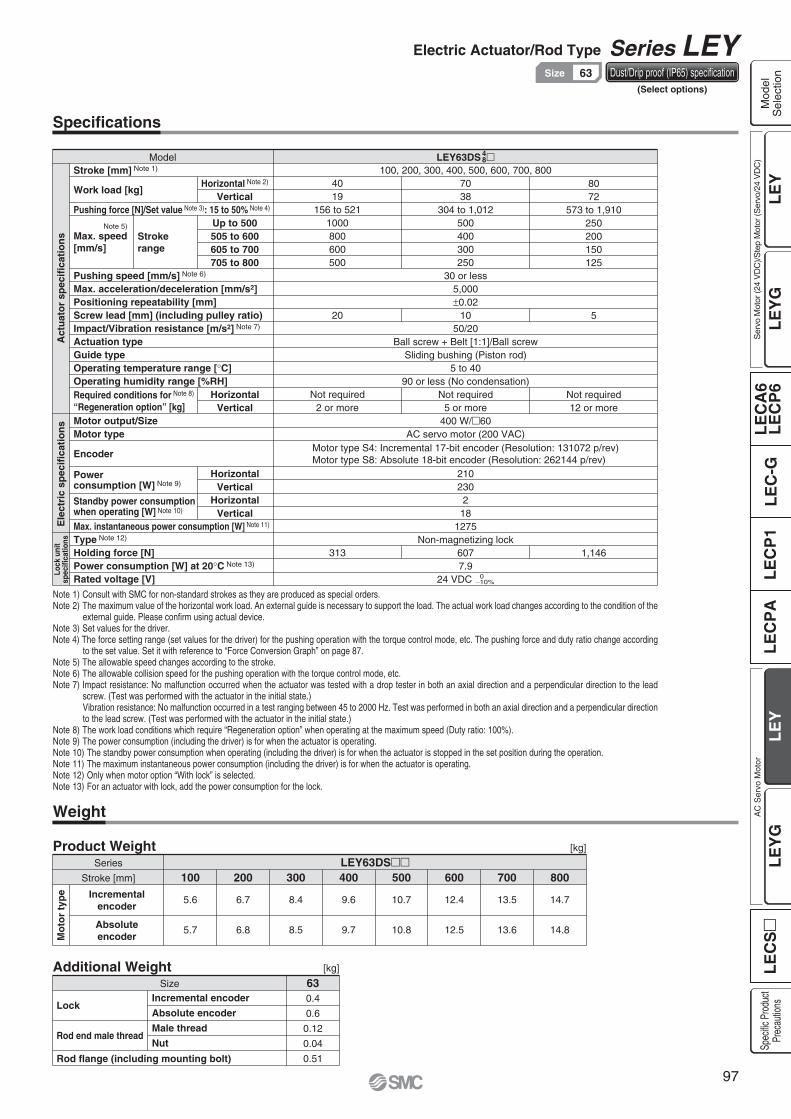
Specifications
Model LEY63DS
4019
156 to 5211000800600500
20
Not required2 or more
313
100, 200, 300, 400, 500, 600, 700, 8007038
304 to 1,012500400300250
30 or less5,0000.0210
50/20Ball screw + Belt [1:1]/Ball screw
Sliding bushing (Piston rod)5 to 40
90 or less (No condensation)Not required
5 or more400 W/ 60
AC servo motor (200 VAC)
210230
218
1275Non-magnetizing lock
6077.9
24 VDC
8072
573 to 1,910250200150125
5
Not required12 or more
1,146
Stroke [mm] Note 1)
Work load [kg]
Pushing force [N]/Set value Note 3): 15 to 50% Note 4)
Pushing speed [mm/s] Note 6)
Max. acceleration/deceleration [mm/s2]Positioning repeatability [mm]Screw lead [mm] (including pulley ratio)Impact/Vibration resistance [m/s2] Note 7)
Actuation typeGuide typeOperating temperature range [ C]Operating humidity range [%RH]
Motor output/SizeMotor type
Encoder
Max. instantaneous power consumption [W] Note 11)
Type Note 12)
Holding force [N]Power consumption [W] at 20 C Note 13)
Rated voltage [V]
Horizontal Note 2)
Vertical
HorizontalVertical
HorizontalVertical
HorizontalVertical
Up to 500505 to 600605 to 700705 to 800
Act
uat
or
spec
ific
atio
ns
Ele
ctri
c sp
ecif
icat
ion
sM
oto
r ty
pe
Lock
uni
tsp
ecifi
catio
ns
Note 5)
Max. speed[mm/s]
Stroke range
Required conditions for Note 8) “Regeneration option” [kg]
48
Note 1) Consult with SMC for non-standard strokes as they are produced as special orders.Note 2) The maximum value of the horizontal work load. An external guide is necessary to support the load. The actual work load changes according to the condition of the
external guide. Please confirm using actual device.Note 3) Set values for the driver.Note 4) The force setting range (set values for the driver) for the pushing operation with the torque control mode, etc. The pushing force and duty ratio change according
to the set value. Set it with reference to “Force Conversion Graph” on page 87.Note 5) The allowable speed changes according to the stroke.Note 6) The allowable collision speed for the pushing operation with the torque control mode, etc.Note 7) Impact resistance: No malfunction occurred when the actuator was tested with a drop tester in both an axial direction and a perpendicular direction to the lead
screw. (Test was performed with the actuator in the initial state.)Vibration resistance: No malfunction occurred in a test ranging between 45 to 2000 Hz. Test was performed in both an axial direction and a perpendicular direction to the lead screw. (Test was performed with the actuator in the initial state.)
Note 8) The work load conditions which require “Regeneration option” when operating at the maximum speed (Duty ratio: 100%).Note 9) The power consumption (including the driver) is for when the actuator is operating.Note 10) The standby power consumption when operating (including the driver) is for when the actuator is stopped in the set position during the operation.Note 11) The maximum instantaneous power consumption (including the driver) is for when the actuator is operating.Note 12) Only when motor option “With lock” is selected.Note 13) For an actuator with lock, add the power consumption for the lock.
Motor type S4: Incremental 17-bit encoder (Resolution: 131072 p/rev)Motor type S8: Absolute 18-bit encoder (Resolution: 262144 p/rev)
010%
Weight
Series
Stroke [mm] 100LEY63DS
200 300 400 500 600 700 800Incremental
encoder
Absoluteencoder
Product Weight
Additional Weight
[kg]
[kg]
Size 630.4
0.6
0.12
0.04
0.51
5.6
5.7
6.7
6.8
8.4
8.5
9.6
9.7
10.7
10.8
12.4
12.5
13.5
13.6
14.7
14.8
Lock
Rod end male thread
Rod flange (including mounting bolt)
Incremental encoder
Absolute encoder
Male thread
Nut
Powerconsumption [W] Note 9)
Standby power consumptionwhen operating [W] Note 10)
97
Electric Actuator/Rod Type Series LEY63Size Dust/Drip proof (IP65) specification
(Select options)
LE
YL
EC
SL
EC
A6
LE
CP
6L
EC
-GL
EC
P1
LE
CP
AL
EY
GL
EY
LE
YG
Mod
elS
elec
tion
Ser
vo M
otor
(24
VD
C)/S
tep
Mot
or (S
ervo
/24
VD
C)
AC
Ser
vo M
otor
Spec
ific P
rodu
ctPr
ecau
tions

Construction
In-line motor type: LEY63
Component PartsDescription Material Note
Aluminum alloy
Alloy steel
Resin/Alloy steel
Aluminum alloy
Stainless steel
Aluminum alloy
Aluminum alloy
Free cutting carbon steel
Resin
Stainless steel
—
Resin
Aluminum alloy
Anodized
Hard chrome anodized
Nickel plated
Coating
Body
Ball screw shaft
Ball screw nut
Piston
Piston rod
Rod cover
Bearing holder
Socket
Wear ring
Wear ring holder
Magnet
Rotation stopper
Motor block
No.
1
2
3
4
5
6
7
8
9
10
11
12
13
Description Material Note
Aluminum alloy
Stainless steel
Aluminum alloy
Urethane
Lead bronze cast
NBR
—
Alloy steel
Steel for spring
—
Free cutting carbon steel
Alloy steel
Coating
Hard chrome anodized
Phosphate coated
Nickel plated
Trivalent chromated
Motor adapter
Spacer A
Hub
Spider
Bushing
Seal
Bearing
Lock nut
Retaining ring
Motor
Socket (Male thread)
Nut
No.
14
15
16
17
18
19
20
21
22
23
24
25
When rod end male thread selected
98
Series LEY63Size Dust/Drip proof (IP65) specification
(Select options)

Dimensions: In-line Motor
LEY63D
End male thread: LEY63 - M IP65 (Dust/Drip proof specification): LEY63D - P
Note 1) Range within which the rod can move. Make sure a workpiece mounted on the rod does not interfere with the workpieces and facilities around the rod.
Note 2) The direction of rod end width across flats ( K) differs depending on the products.
The measurement 76.4 is when the unit is in the encoder Z phasedetecting position. At this position, 4 mm at the end.
SizeStroke range
[mm]
Incremental encoder
Without lock With lock Without lock With lock
Absolute encoder
63Up to 200
205 to 500
505 to 800
B
190.7
225.7
260.7
V
60
A338.3
373.3
408.3
W
110.2
Z
8.1
W
138.8
Z
8.1
W
98.5
Z
8.1
W
138
Z
8.1
A366.9
401.9
436.9
A326.6
361.6
396.6
A366.1
401.1
436.1
C
21
D
40
EH
76
EV
82
H
M16 x 2
J
44
K
36
L
37.4
M
60
O1
M8 x 1.25
R
16
S
78
T
83
U
5
SizeStroke range
[mm]
63Up to 200
205 to 500
505 to 800
[mm]
UVWB + Stroke
A + Stroke
Rod operating range Note 1)
(Stroke + 8 mm)
4 1
L
M
K Note 2)
MEHS
JE
VTZ
Hthread depth C
4 x O1
thread depth R
Encoder Z phase detecting position
M18
x 1
.5
76.4
39
26
Width across flats 27
øD
11
10.5
50
Rc1/8Vent hole tap
When using the dust/drip proof (IP65), correctly mount the fitting and tubing to the vent hole tap, and then place the end of the tubing in an area not exposed to dust or water. The fitting and tubing should be provided separately by the customer.Select [Applicable tubing O.D.: ø4 or more, Connection thread: Rc1/8].
99
Electric Actuator/Rod Type Series LEY63Size Dust/Drip proof (IP65) specification
(Select options)
LE
YL
EC
SL
EC
A6
LE
CP
6L
EC
-GL
EC
P1
LE
CP
AL
EY
GL
EY
LE
YG
Mod
elS
elec
tion
Ser
vo M
otor
(24
VD
C)/S
tep
Mot
or (S
ervo
/24
VD
C)
AC
Ser
vo M
otor
Spec
ific P
rodu
ctPr
ecau
tions

Dimensions: In-line Motor
Body bottom tapped: LEY63 - U
Rod flange: LEY63 - F
Material: Carbon steel (Nickel plated)
L
37.4
MA
38
MC
24
45
58
86
MD
50
60.5
67
81
MH
44
ML
65
100
135
MO
M8 x 1.25
MR
10
XA
6
XB
7
SizeStroke range
[mm]
63
20 to 74
75 to 124
125 to 200
201 to 500
501 to 800
[mm]
Included parts Flange Body mounting bolt
MH
L MAMC
ML + Stroke
MD
6 x MOthread depth MR
Section XX
øXA H9 depth XA
Section XX details
28.4
9
108
92
60 80
4 x ø9
XAXBXA H9
100
Series LEY63Size Dust/Drip proof (IP65) specification
(Select options)

2532
S2
S3
S6
S7
Symbol Type Compatible driversOutput
[W]Actuator
size
AC servo motor(Incremental encoder) LECSA -S1
LECSA -S3
LECSB -S5LECSC -S5LECSS -S5
LECSB -S7LECSC -S7LECSS -S7
25
32
25
32
100
200
100
200
AC servo motor(Incremental encoder)
AC servo motor(Absolute encoder)
AC servo motor(Absolute encoder)
How to Order
SizeNilD
Top mountingIn-line
Motor mounting position Motor type
30to
500
30to
500
Refer to the applicable stroke table.
Stroke [mm]
Rod end threadNil
M
Rod end female threadRod end male thread
(1 rod end nut is included.)
I/O connectorNilH
Without connectorWith connector
SB A12S225 100LEY X5
RoHS
Motor optionNilB
Without optionWith lock
When “With lock” is selected for the top mounting type, the motor body will stick out of the end of the body for size 25 with strokes 30 or less. Check for interference with workpieces before selecting a model.
For motor type S2 and S6, the compatible driver part number suffixes are S1 and S5 respectively.
NilSR
Without cableStandard cable
Robotic cable (Flexible cable)
Cable type
The motor and encoder cables are included. (The lock cable is also included when the motor with lock option is selected.)
Standard cable entry direction is Top mounting: (A) Axis side In-line: (B) Counter axis side
(Refer to page 131 for details.)Nil25A
Without cable25
10
Cable length [m]
The length of the encoder, motor and lock cables are the same.
ABC
LEY251263
LEY3216 (20)8 (10)4 (5)
Symbol Lead [mm]
The values shown in ( ) are the equivalent lead which includes the pulley ratio for size 32 top mounting type.
Driver type
NilA1A2B1B2C1C2S1S2
—100 to 120200 to 230100 to 120200 to 230100 to 120200 to 230100 to 120200 to 230
Without driverLECSA1LECSA2LECSB1LECSB2LECSC1LECSC2LECSS1LECSS2
Compatible drivers Power supply voltage [V]
Dust/Drip proof specification
X5
For auto switches, refer to page 27.
When the driver type is selected, the cable is included. Select cable type and cable length.Example)S2S2: Standard cable (2 m) + Driver (LECSS2)S2 : Standard cable (2 m)Nil : Without cable and driver
NilULFG
TypeMotor mounting positionTop mounting
3
In-line
—
—
Ends tapped (Standard) 2
Body bottom tappedFoot
Rod flange 2
Head flange 2
Symbol
Mounting 1
1 Mounting bracket is shipped together, (but not assembled).
2 For horizontal cantilever mounting with the rod flange, head flange and ends tapped, use the actuator within the following stroke range.LEY25: 200 or lessLEY32: 100 or less
3 Head flange is not available for the LEY32.
Consult with SMC for non-standard strokes as they are produced as special orders.
Applicable stroke table
LEY25LEY32
30 50 100 150 200 250 300 350 400
—
450
—
500Stroke
Model
StandardManufacturable
stroke range [mm]
15 to 40020 to 500
Motor
101
Electric Actuator/Rod Type
LEY25, 32Series LEY-X5
Dust/Drip proof (IP65) specification
AC Servo Motor
LE
YL
EC
SL
EC
A6
LE
CP
6L
EC
-GL
EC
P1
LE
CP
AL
EY
GL
EY
LE
YG
Mod
elS
elec
tion
Ser
vo M
otor
(24
VD
C)/S
tep
Mot
or (S
ervo
/24
VD
C)
AC
Ser
vo M
otor
Spec
ific P
rodu
ctPr
ecau
tions

Specifications
Weight
Size 25 32
Lock
Rod end male thread
Foot (2 sets including mounting bolt)Rod flange (including mounting bolt)Head flange (including mounting bolt)
Incremental encoderAbsolute encoderMale threadNut
0.200.300.030.020.08
0.17
0.400.660.030.020.14
0.20
[kg]Additional Weight
4514528
445
65175
28
724
65175
28
724
Model
188
65 to 131
900600—
12
8 or more3 or more
131
5016
127 to 255
450300—
35 or less5,0000.026
50/20Ball screw + Belt/Ball screwSliding bushing (Piston rod)
5 to 4090 or less (No condensation)
31 or more2 or more
100 W/ 40AC servo motor (100/200 VAC)
2556.3
30, 50, 100, 150, 200250, 300, 350, 400
30, 50, 100, 150, 200, 250300, 350, 400, 450, 500
30, 50, 100, 150, 200, 250300, 350, 400, 450, 500
Motor type S2, S3: Incremental 17-bit encoder (Resolution: 131072 p/rev)Motor type S6, S7: Absolute/incremental dual 18-bit encoder (Resolution: 262144 p/rev)
5030
242 to 485
225150—
3
Not required2 or more
485
309
79 to 157
1200
800
20 Note 6)
15 or more6 or more
157
6019
154 to 308
600
40030 or less
10 Note 6)
Ball screw + Belt
IP65
Not required7 or more
Non-magnetizing lock3087.9
24 VDC
6037
294 to 588
300
200
5 Note 6)
Not required11 or more
588
3012
98 to 197
1000
640
16
23 or more6 or more
197
6024
192 to 385
500
32030 or less
8
Ball screw
Not required7 or more
3857.9
6046
368 to 736
250
160
4
Not required12 or more
736
5,0000.02
50/20
Sliding bushing (Piston rod)
5 to 4090 or less (No condensation)
200 W/ 60AC servo motor (100/200 VAC)
Pushing speed [mm/s] Note 5)
Max. acceleration/deceleration [mm/s2]Positioning repeatability [mm]Lead [mm]Impact/Vibration resistance [m/s2] Note 7)
Actuation typeGuide typeEnclosureOperating temperature range [ C]Operating humidity range [%RH]
Motor output/SizeMotor type
Encoder
Max. instantaneous power consumption [W] Note 11)
Type Note 12)
Holding force [N]Power consumption [W] at 20 C Note 13)
Rated voltage [V]
Work load [kg]
Pushing force [N] Note 3)
(Set value: 15 to 30%)
Stroke [mm] Note 1)
Horizontal Note 2)
Vertical
Act
uat
or
spec
ific
atio
ns
Ele
ctri
c sp
ecif
icat
ion
sLo
ck u
nit
spec
ifica
tions
Note 4)
Max. speed[mm/s]
Required conditions for Note 8)
“Regeneration option” [kg]
Strokerange
Up to 300305 to 400405 to 500
HorizontalVertical
HorizontalVertical
HorizontalVertical
LEY32DS (In-line)37LEY32S (Top mounting)3
7LEY25S /LEY25DS26
26
010%
[kg]Product WeightLEY25S (Motor mounting position: Top mounting) LEY32S (Motor mounting position: Top mounting)30 50 100 150 200 250 300 350 400 30 50 100 150 200 250 300 350 400 450 500
LEY25DS (Motor mounting position: In-line) LEY32DS (Motor mounting position: In-line)50 100 150 200 250 300 350 400 30 50 100 150 200 250 300 350 400 450 500
1.311.37
1.381.44
1.551.61
1.811.87
1.992.05
2.162.22
2.342.40
2.512.57
2.692.75
2.422.36
2.532.47
2.822.76
3.293.23
3.573.51
3.853.79
4.144.08
4.424.36
4.704.64
4.984.92
5.265.20
1.341.40
1.411.47
1.581.64
1.841.90
2.022.08
2.192.25
2.372.43
2.542.60
2.722.78
2.442.38
2.552.49
2.842.78
3.313.25
3.593.53
3.873.81
4.164.10
4.444.38
4.724.66
5.004.94
5.285.22
Mot
orty
peM
otor
type
SeriesStroke [mm]
Series
Incremental encoderAbsolute encoder
Incremental encoderAbsolute encoder
Stroke [mm] 30
Power consumption [W] Note 9)
Standby power consumptionwhen operating [W] Note 10)
Note 1) Consult with SMC for non-standard strokes as they are produced as special orders.Note 2) The maximum value of the horizontal work load. An external guide is necessary to
support the load. The actual work load changes according to the condition of the external guide. Please confirm using actual device.
Note 3) The force setting range (set values for the driver) for the pushing operation with the torque control mode, etc. Set it with reference to “Force Conversion Graph” on page 86.
Note 4) The allowable speed changes according to the stroke.Note 5) The allowable collision speed for the pushing operation with the torque control mode, etc.Note 6) Equivalent lead which includes the pulley ratio [1.25:1]Note 7) Impact resistance: No malfunction occurred when the actuator was tested with a drop
tester in both an axial direction and a perpendicular direction to the lead screw. (Test was performed with the actuator in the initial state.)Vibration resistance: No malfunction occurred in a test ranging between 45 to 2000 Hz.
Test was performed in both an axial direction and a perpendicular direction to the lead screw. (Test was performed with the actuator in the initial state.)
Note 8) The work load conditions which require “Regeneration option” when operating at the maximum speed (Duty ratio: 100%). Order the regeneration option separately. For details and order numbers, refer to “Required Conditions for Regeneration Option” on pages 84 and 85.
Note 9) The power consumption (including the driver) is for when the actuator is operating.Note 10) The standby power consumption when operating (including the driver) is for when the
actuator is stopped in the set position during the operation.Note 11) The maximum instantaneous power consumption (including the driver) is for when the
actuator is operating.Note 12) Only when motor option “With lock” is selected.Note 13) For an actuator with lock, add the power consumption for the lock.
102
Series LEY-X5Dust/Drip proof (IP65) specification

When rod end male thread selected
Cable is shipped together.
Construction
Motor top mounting type: LEY
Component PartsDescription Material Note
Aluminum alloy
Alloy steel
Resin/Alloy steel
Aluminum alloy
Stainless steel
Aluminum alloy
Aluminum alloy
POM
Free cutting carbon steel
Free cutting carbon steel
Lead bronze cast
Urethane
—
Aluminum die-cast
Aluminum die-cast
—
Stainless steel
POM
Anodized
Hard chrome anodized
Nickel plated
Nickel plated
Coating
Coating
Stroke 101 mm or more
Stroke 101 mm or more
Body
Ball screw (shaft)
Ball screw nut
Piston
Piston rod
Rod cover
Housing
Rotation stopper
Socket
Connected shaft
Bushing
Bumper
Bearing
Return box
Return plate
Magnet
Wear ring holder
Wear ring
No.
1
2
3
4
5
6
7
8
9
10
11
12
13
14
15
16
17
18
Description Material Note
Aluminum alloy
Aluminum alloy
—
Aluminum alloy
Stainless steel
Nylon
Steel for spring
Aluminum alloy
—
Felt
NBR
NBR
NBR
Aluminum alloy
Aluminum alloy
Urethane
Free cutting carbon steel
Alloy steel
Nickel plated
Coating
Coating
Nickel plated
Zinc chromated
Screw shaft pulley
Motor pulley
Belt
Bearing stopper
Parallel pin
Scraper
Retaining ring
Motor adapter
Motor
Lub-retainer
O-ring
Gasket
O-ring
Motor block
Hub
Spider
Socket (Male thread)
Nut
No.
19
20
21
22
23
24
25
26
27
28
29
30
31
32
33
34
35
36
In-line motor type: LEY D2532 25
32
No. Size
212532
Order no.LE-D-2-2LE-D-2-4
Replacement Parts (Top mounting only)/BeltApplied portion Order no.
GR-S-010 (10 g)GR-S-020 (20 g)
Piston rod
Replacement Parts/Grease Pack
Apply grease on the piston rod periodically.Grease should be applied at 1 million cycles or 200 km, whichever comes sooner.
103
Electric Actuator/Rod Type Series LEY-X5Dust/Drip proof (IP65) specification
LE
YL
EC
SL
EC
A6
LE
CP
6L
EC
-GL
EC
P1
LE
CP
AL
EY
GL
EY
LE
YG
Mod
elS
elec
tion
Ser
vo M
otor
(24
VD
C)/S
tep
Mot
or (S
ervo
/24
VD
C)
AC
Ser
vo M
otor
Spec
ific P
rodu
ctPr
ecau
tions

øD
øD
VE
VJ
K Note 2)
MEH PC
4 x O1 thread depth R
MPA
øPB
Vent hole Note 3)
Applicable tubing O.D. ø4
H thread depth C
A + Stroke
B + Stroke
Y
L SM
TZ
M
U
4 x O1 thread depth R
XW
Encoder Z phase detecting position
Rod operating range Note 1)
(Stroke + 4 mm)
2 1
JPC
EV
ZT
SEHM
M
K Note 2)
U
RWA + Stroke
B + Stroke
Y
4 x O1 thread depth R L
H thread depth C
Encoder Z phase detecting position
Rod operating range Note 1)
(Stroke + 4 mm)
2 1
Vent hole Note 3)
Applicable tubing O.D. ø4
øP
B
PA
Dimensions
Motor top mounting type: LEY
Note 1) Range within which the rod can move. Make sure a workpiece mounted on the rod does not interfere with the workpieces and facilities around the rod.Note 2) The direction of rod end width across flats ( K) differs depending on the products.Note 3) The vent hole is the port for releasing to atmosphere. Do not apply pressure to this hole.
Attach tubing to the vent hole and place the end of the tubing so it is not exposed to dust or water.
15 to 100101 to 40020 to 100101 to 500
Stroke range(mm)
Size
25
32
8
10
M5 x 0.8
M6 x 1.0
34
40
14.5
18.5
17
22
24
31
M8 x 1.25
M8 x 1.25
45.5
56.5
44
51
20
25
13
13
116141130160
130.5155.5148.5178.5
R
15.6
15.6
PA
9.3
9.3
PB
40
60
VO1MLKJHEVEHDCBA
15 to 100101 to 40020 to 100101 to 500
Stroke range(mm)
Size
25
32
156.5
156.1
123.5
116.1
115.4
116.6
82.4
76.6
156.9
156.8
123.9
116.8
120
128.2
14.8
15.3
1
1
92
118
46
60
XWXWXWX
15.8
17.1
14.1
17.1
15.8
17.1
14.1
17.1
ZZZZWPC
51
61
Y
87
88.2
Incremental encoderWithout lock With lock
Absolute encoderWithout lock With lockUTS
15 to 100101 to 40020 to 100101 to 500
Stroke range(mm)
Size
25
32
M8 x 1.25
M8 x 1.25
45.5
56.5
44
51
20
25
13
13
136.5161.5156 186
274.5299.5290.6320.6
123.5
116.1
82.4
76.6
233.4258.4251.1281.1
123.9
116.8
274.9299.9291.3321.3
87
88.2
238 263 262.7292.7
EVEHDCB
H
15 to 100101 to 40020 to 100101 to 500
Stroke range(mm)
Size
25
32
15.3
15.3
1.5
1
46.5
61
45
60
40
60
9.3
9.3
8
10
M5 x 0.8
M6 x 1.0
34
40
14.5
18.5
17
22
24
31
PC
71.5
87
YUTSVPBPAR
15.6
15.6
WAWA
Incremental encoderWithout lock With lock
WAW
16.3
17.1
14.6
17.1
16.3
17.1
14.6
17.1
ZZ ZZA
Absolute encoderWithout lock With lock
O1MLKJ
2532
For the rod end male thread, refer to page 93.For the mounting dimensions, refer to page 18.
104
Series LEY-X5Dust/Drip proof (IP65) specification

105
LE
YL
EC
SL
EC
A6
LE
CP
6L
EC
-GL
EC
P1
LE
CP
AL
EY
GL
EY
LE
YG
Mod
elS
elec
tion
Ser
vo M
otor
(24
VD
C)/S
tep
Mot
or (S
ervo
/24
VD
C)
AC
Ser
vo M
otor
Spec
ific P
rodu
ctPr
ecau
tions

Moment Load Graph
Selection conditions
Mounting position
Vertical Horizontal
Max. speed [mm/s]
Graph (Sliding bearing type)
Graph (Ball bushing bearing type)
“Speed–Vertical Work Load Graph”
,
,
Over 200
,
,
L L
m mL
m
L
m
200 or less
,
,
Vertical Mounting, Sliding Bearing 70 stroke or less Over 75 stroke
Over 40 stroke
Vertical Mounting, Ball Bushing Bearing 35 stroke or less
The limit of vertical load mass varies depending on “lead” and “speed”.Check “Speed–Vertical Work Load Graph” on page 108.
The limit of vertical load mass varies depending on “lead” and “speed”.Check “Speed–Vertical Work Load Graph” on page 108.
Electric Actuator/Guide Rod Type
Series LEYGModel Selection
For the sliding bearing type, the speed is restricted with a horizontal/moment load.
Eccentric distance L [mm]
Load
mas
s m
[kg]
1
100
10
10 100
LEYG32M
LEYG25M
Eccentric distance L [mm]
Load
mas
s m
[kg]
0.1
1
100
10
10 100
LEYG32M
LEYG25M
Eccentric distance L [mm]
Load
mas
s m
[kg]
0.1
1
100
10
10 100
LEYG32L
LEYG25L
Eccentric distance L [mm]
Load
mas
s m
[kg]
0.1
1
100
10
10 100
LEYG32L
LEYG25L
1000 1000
10001000
AC Servo Motor
106

Transfer speed [m/min]
Wor
k lo
ad m
[kg]
504020 30105
100504030
20
10543
2
1
LEYG M (Sliding bearing)
L 5
0 m
m
m
Caution
Operating Range when Used as Stopper
Horizontal Mounting, Sliding Bearing L = 50 mm Max. speed = 200 mm/s or less
L = 50 mm Max. speed = Over 200 mm/s L = 100 mm Max. speed = Over 200 mm/s
Handling PrecautionsNote 1) When used as a stopper, select a
model with 30 stroke or less.Note 2) LEYG L (ball bushing bearing)
cannot be used as a stopper.Note 3) Workpiece collision in series with
guide rod cannot be permitted (Fig. a).
Note 4) The body should not be mounted on the end. It must be mounted on the top or bottom (Fig. b).
L = 100 mm Max. speed = 200 mm/s or less
Horizontal Mounting, Ball Bushing Bearing L = 50 mm Max. speed = 200 mm/s or less
L = 50 mm Max. speed = Over 200 mm/s L = 100 mm Max. speed = Over 200 mm/s
L = 100 mm Max. speed = 200 mm/s or less
LEYG32M
LEYG25M
Moment Load Graph
Fig. a
Fig. b
m
LEYG32M LEYG32M
LEYG25M LEYG25M
Load
mas
s m
[kg]
0.1
1
10
Stroke [mm]100 10007010 75
LEYG32M
LEYG25M
LEYG32M
LEYG25M
Load
mas
s m
[kg]
0.1
1
10
Stroke [mm]100 10007010 75
LEYG32M
LEYG25MLEYG32M
LEYG25M
Load
mas
s m
[kg]
0.1
1
10
Stroke [mm]100 10007010 75
LEYG32M
LEYG25M
LEYG32M
LEYG25MLo
ad m
ass
m [k
g]
0.1
1
10
Stroke [mm]100 10007010 75
LEYG32L LEYG32L
LEYG25L LEYG25L
Load
mas
s m
[kg]
0.1
1
10
Stroke [mm]100 1000403510
LEYG32L LEYG32L
LEYG25L LEYG25L
Load
mas
s m
[kg]
0.1
1
10
Stroke [mm]100 1000403510
120 125
120 125
LEYG32L LEYG32L
LEYG25L LEYG25L
Load
mas
s m
[kg]
0.1
1
10
Stroke [mm]100 1000403510
120 125
LEYG32L LEYG32L
LEYG25L LEYG25L
Load
mas
s m
[kg]
0.1
1
10
Stroke [mm]100 1000403510
120 125
107
Model Selection Series LEYG
LE
YL
EC
SL
EC
A6
LE
CP
6L
EC
-GL
EC
P1
LE
CP
AL
EY
GL
EY
LE
YG
Mod
elS
elec
tion
Ser
vo M
otor
(24
VD
C)/S
tep
Mot
or (S
ervo
/24
VD
C)
Spec
ific P
rodu
ctPr
ecau
tions
AC
Ser
vo M
otor

Speed–Vertical Work Load Graph/Required Conditions for “Regeneration Option”
Required conditions for “Regeneration option”LEYG25 (Motor mounting position: Top mounting/In-line)
LEYG32 (Motor mounting position: Top mounting) LEYG32D (Motor mounting position: In-line)
Speed–Horizontal Work Load Graph/Required Conditions for “Regeneration Option”
Regeneration option required when using product above “Regeneration” line in graph. (Order separately)
Required conditions for “Regeneration option”LEYG25 (Motor mounting position: Top mounting/In-line)
LEYG32 (Motor mounting position: Top mounting) LEYG32D (Motor mounting position: In-line)
Regeneration option required when using product above “Regeneration” line in graph. (Order separately)
0 200 400 600 800 1000 14001200Speed [mm/s]
Wor
k lo
ad [k
g]
0
10
40
30
20
Lead 3: LEYG25 C
Lead 6: LEYG25 B
Lead 12: LEYG25 A
Lead 5: LEYG32 C
Lead 10: LEYG32 B
Lead 20: LEYG32 A
0 200 400 600 800 1000 14001200Speed [mm/s]
Wor
k lo
ad [k
g]
0
10
50
30
40
20
0 200 400 600 800 1000 14001200Speed [mm/s]
Wor
k lo
ad [k
g]
0
10
60
50
30
40
20
Lead 4: LEYG32D C
Lead 8: LEYG32D B
Lead 16: LEYG32D A
0 200 400 600 800 1000 14001200Speed [mm/s]
Wor
k lo
ad [k
g]
0
20
10
70
50
60
40
30
Lead 3: LEYG25 C
Lead 6: LEYG25 B
Lead 12: LEYG25 A
Lead 5: LEYG32 C
Lead 10: LEYG32 B
Lead 20: LEYG32 A
0 200 400 600 800 1000 14001200Speed [mm/s]
Wor
k lo
ad [k
g]
0
20
10
80
70
50
60
40
30
Lead 4: LEYG32D C
Lead 8: LEYG32D B
Lead 16: LEYG32D A
0 200 400 600 800 1000 14001200Speed [mm/s]
Wor
k lo
ad [k
g]
0
20
10
80
70
50
60
40
30
B
B
A
B
A
A
B
A
A
Regenerative conditions
Duty ratio 50% or more
Duty ratio 100%
Operating conditions
A
B
Vertical transfer
LEC-MR-RB032
“Regeneration Option” Models
Regenerative conditions
Duty ratio 50% or more
Duty ratio 100%
Operating conditions
A
B
Horizontal transfer
LEC-MR-RB032
“Regeneration Option” Models
108
Series LEYG
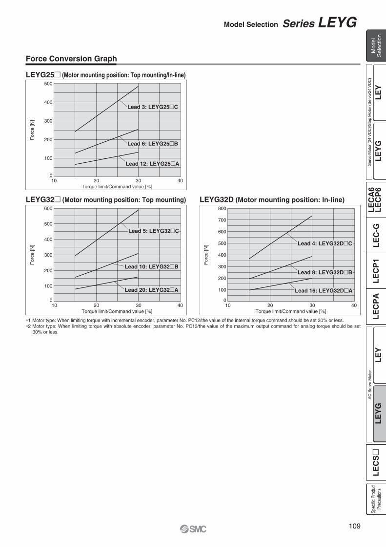
For
ce [N
]
Torque limit/Command value [%]
500
400
300
200
100
02010 4030
For
ce [N
]
Torque limit/Command value [%]
800
700
600
500
400
300
200
100
02010 4030
For
ce [N
]
Torque limit/Command value [%]
600
500
400
300
200
100
02010 4030
Lead 3: LEYG25 C
Lead 5: LEYG32 C
Lead 10: LEYG32 B
Lead 20: LEYG32 A
Lead 6: LEYG25 B
Lead 12: LEYG25 A
Lead 4: LEYG32D C
Lead 8: LEYG32D B
Lead 16: LEYG32D A
Force Conversion Graph
LEYG25 (Motor mounting position: Top mounting/In-line)
LEYG32D (Motor mounting position: In-line)LEYG32 (Motor mounting position: Top mounting)
1 Motor type: When limiting torque with incremental encoder, parameter No. PC12/the value of the internal torque command should be set 30% or less.2 Motor type: When limiting torque with absolute encoder, parameter No. PC13/the value of the maximum output command for analog torque should be set
30% or less.
109
Model Selection Series LEYG
LE
YL
EC
SL
EC
A6
LE
CP
6L
EC
-GL
EC
P1
LE
CP
AL
EY
GL
EY
LE
YG
Mod
elS
elec
tion
Ser
vo M
otor
(24
VD
C)/S
tep
Mot
or (S
ervo
/24
VD
C)
Spec
ific P
rodu
ctPr
ecau
tions
AC
Ser
vo M
otor

How to Order
LEYG 25 100B 2 A1
2532
S
Applicable stroke table
LEYG25LEYG32
Stroke(mm)Model
30 50 100 150 200 250 300
15 to 30020 to 300
Manufacturablestroke range
Note) Consult with SMC for non-standard strokes as they are produced as special orders.
Size
30to
300 Refer to the table below for details.
30to
300
Stroke [mm]NilB
Without optionWith lock
Motor option
NilD
Top mountingIn-line
Motor mounting positionML
Sliding bearingBall bushing bearing
Bearing type
S2
The values shown in ( ) are the lead for size 32 top mounting types. (Equivalent lead which includes the pulley ratio [1.25:1])
ABC
LEYG251263
LEYG3216 (20)8 (10)4 (5)
Symbol
Lead [mm]
LEYG25, 32Series LEYGElectric Actuator/Guide Rod Type
M
The motor and encoder cables are included. (The lock cable is also included when the motor with lock option is selected.)
Standard cable entry direction is Top mounting: (A) Axis side In-line: (B) Counter axis side
(Refer to page 131 for details.)
Cable typeNilSR
Without cableStandard cable
Robotic cable (Flexible cable)
Guide optionNilF
Without optionWith grease retaining function
Only available for size 25 and 32 sliding bearings. (Refer to “Construction” on page 113.)
Nil25A
Without cable2510
Cable length [m]
For auto switches, refer to pages 20 and 21.
S2
S3
100
200
25
32
S6
S7
100
200
25
32
Symbol Type Actuatorsize
Output[W]
AC servo motor(Incremental encoder)
AC servo motor(Incremental encoder)
AC servo motor(Absolute encoder)
AC servo motor(Absolute encoder)
LECSA -S1
LECSA -S3
LECSB -S5LECSC -S5LECSS -S5
LECSB -S7LECSC -S7LECSS -S7
Compatibledrivers 2
Motor type 1
1: For motor type S2 and S6, the compatible driver part number suffixes are S1 and S5 respectively.
2: For details about the driver, refer to page 120.
RoHS
AC Servo Motor
The length of the encoder, motor and lock cables are the same.
Standard
110

Motor mounting position: Top mounting Motor mounting position: In-line
NilH
Without connectorWith connector
I/O connector
Use of auto switches for the guide rod type LEYG seriesInsert the auto switch from the front side with rod (plate) sticking out.For the parts hidden behind the guide attachment (Rod stick out side), the auto switch cannot be fixed.Consult with SMC when using auto switch on the rod stick out side.
Compatible Drivers
Driver type
LECSA
Up to 7
—
USB communication
LECSB
—
—
USB communication, RS422 communication
Page 120
100 to 120 VAC (50/60 Hz)200 to 230 VAC (50/60 Hz)
Pulse input type/Positioning type
Pulse input type
LECSC
Up to 255 (2 stations occupied)
—
CC-Link
USB communication, RS422 communication
CC-Link directinput type
LECSS
—
—
SSCNET III type
USB communication
SSCNET III type
Series
Number of point tables
Pulse input
Applicable network
Control encoder
Communication function
Power supply voltage (V)
Reference page
Incremental17-bit encoder
Absolute18-bit encoder
Absolute18-bit encoder
Absolute18-bit encoder
Driver type
NilA1A2B1B2C1C2S1S2
Without driverLECSA1-SLECSA2-SLECSB1-SLECSB2-SLECSC1-SLECSC2-SLECSS1-SLECSS2-S
—100 to 120200 to 230100 to 120200 to 230100 to 120200 to 230100 to 120200 to 230
Power supply voltage (V)Compatible drivers
When the driver type is selected, the cable is included. Select cable type and cable length.Example)S2S2: Standard cable (2 m) + Driver (LECSS2)S2 : Standard cable (2 m)Nil : Without cable and driver
111
Electric Actuator/Guide Rod Type Series LEYG
LE
YL
EC
SL
EC
A6
LE
CP
6L
EC
-GL
EC
P1
LE
CP
AL
EY
GL
EY
LE
YG
Spec
ific P
rodu
ctPr
ecau
tions
AC
Ser
vo M
otor
Mod
elS
elec
tion
Ser
vo M
otor
(24
VD
C)/S
tep
Mot
or (S
ervo
/24
VD
C)

Specifications
Weight
Model
187
65 to 131
900
5015
127 to 255
45035 or less
5,0000.02
5029
242 to 485
225
307
79 to 157
1200
6017
154 to 308
60030 or less
6035
294 to 588
300
3010
98 to 197
1000
6022
192 to 385
50030 or less
6044
368 to 736
250
30, 50, 100, 150,200, 250, 300
30, 50, 100, 200,250, 300
30, 50, 100, 200,250, 300
LEYG25 S26 (Top mounting)
LEYG25 DS26 (In-line) LEYG32 S3
7 (Top mounting) LEYG32 DS37 (In-line)
Stroke [mm] Note 1)
Pushing speed [mm/s2] Note 4)
Max. acceleration/deceleration [mm/s2]Positioning repeatability [mm]Lead [mm] (including pulley ratio)Impact/Vibration resistance [m/s2] Note 5)
Actuation typeGuide typeOperating temperature range [ C]Operating humidity range [%RH]
Motor output/SizeMotor type
Encoder
Max. instantaneous power consumption [W] Note 9)
Type Note 10)
Holding force [N]Power consumption at 20°C [W] Note 11)
Rated voltage [V]
Work load [kg]Horizontal Note 2)
Vertical
HorizontalVertical
12 650/20
Ball screw + Belt [1:1]/Ball screw
5 to 4090 or less (No condensation)
31 or more1 or more
100 W/ 40AC servo motor (100/200 VAC)
3 20 10
Ball screw + Belt [1:1.25]
5 16
5,0000.02
50/20
5 to 4090 or less (No condensation)
200 W/ 60AC servo motor (100/200 VAC)
8
Ball screw
4
8 or more2 or more
Not required1 or more
15 or more4 or more
Not required5 or more
Not required5 or more
Not required9 or more
23 or more4 or more
Not required9 or more
131
4514528
445
6517528
724
6517528
724
2556.3
485 157 3087.9
Non-magnetizing lock Non-magnetizing lock
Motor type S2, S3: Incremental 17-bit encoder (Resolution: 131072 p/rev)Motor type S6, S7: Absolute 18-bit encoder (Resolution: 262144 p/rev)
24 VDC
588 197 3857.9
736
Act
uat
or
spec
ific
atio
ns
Ele
ctri
c sp
ecif
icat
ion
sLo
ck u
nit
spec
ifica
tions
Mot
orty
peM
otor
type
Mot
orty
peM
otor
type
HorizontalVertical
HorizontalVertical
010%
Series
Incremental encoderAbsolute encoder
LEYG25M LEYG32MStroke [mm] 30 50 100 150 200 250 300 30 50 100 150 200 250 300
1.801.86
1.992.05
2.312.37
2.732.79
3.073.13
3.413.47
3.673.73
3.243.18
3.503.44
4.053.99
4.804.74
5.355.29
5.835.77
6.286.22
Series
Incremental encoderAbsolute encoder
LEYG25L LEYG32LStroke [mm] 30 50 100 150 200 250 300 30 50 100 150 200 250 300
1.811.87
2.022.08
2.262.32
2.692.75
2.953.01
3.273.33
3.513.57
3.243.18
3.513.45
3.9 3.84
4.644.58
5.065.00
5.565.50
5.965.90
Pushing force [N] Note 3)
(Set value: 15 to 30%)
Required conditions for Note 6)
“Regeneration option” [kg]
Max. speed [mm/s]
[kg]Weight: Top Mounting Type
Series
Incremental encoderAbsolute encoder
LEYG25MD LEYG32MDStroke [mm] 30 50 100 150 200 250 300 30 50 100 150 200 250 300
1.831.89
2.022.08
2.342.40
2.762.82
3.103.16
3.443.50
3.703.76
3.263.20
3.523.46
4.074.01
4.824.76
5.375.31
5.855.79
6.306.24
Series
Incremental encoderAbsolute encoder
LEYG25LD LEYG32LDStroke [mm] 30 50 100 150 200 250 300 30 50 100 150 200 250 300
1.841.90
2.052.11
2.292.35
2.722.78
2.983.04
3.303.36
3.543.60
3.263.20
3.533.47
3.923.86
4.664.60
5.085.02
5.585.52
5.985.92
[kg]Weight: In-line Motor Type
Size 25 32
LockIncremental encoderAbsolute encoder
0.200.30
0.400.66
[kg]Additional Weight
Sliding bearing (LEYG M), Ball bushing bearing (LEYG L)
Powerconsumption [W] Note 7)
Standby power consumptionwhen operating [W] Note 8)
Note 1) Consult with SMC for non-standard strokes as they are produced as special orders.Note 2) The maximum value of the horizontal work load. An external guide is necessary to support the load. The actual
work load changes accoding to the condition of the external guide. Please confirm using actual device.Note 3) The force setting range (set values for the driver) for the pushing operation with the torque control mode, etc. Set it
with reference to “Force Conversion Graph” on page 109.Note 4) The allowable collision speed for the pushing operation with the torque control mode, etc.Note 5) Impact resistance: No malfunction occurred when the actuator was tested with a drop tester in both an axial
direction and a perpendicular direction to the lead screw. (Test was performed with the actuator in the initial state.)Vibration resistance: No malfunction occurred in a test ranging between 45 to 2000 Hz. Test was performed in both an axial direction and a perpendicular direction to the lead screw. (Test was performed with the actuator in the initial state.)
Note 6) The work load conditions which require “Regeneration option” when operating at the maximum speed (Duty ratio: 100%). Order the regeneration option separately. For details and order numbers, refer to “Required Conditions for Regeneration Option” on page 108.
Note 7) The power consumption (including the driver) is for when the actuator is operating.Note 8) The standby power consumption when operating (including the driver) is for when the actuator is stopped in the set
position during operation.Note 9) The maximum instantaneous power consumption (including the controller) is for when the actuator is operating.Note 10) Only when motor option “With lock” is selected.Note 11) For an actuator with lock, add the power consumption for the lock.
112
Series LEYG

Construction
No. Description Material Note123456789101112131415161718192021
BodyBall screw shaftBall screw nutPistonPiston rodRod coverHousingRotation stopperSocketConnected shaftBushingBumperBearingReturn boxReturn plateMagnetWear ring holderWear ringScrew shaft pulleyMotor pulleyBelt
Aluminum alloyAlloy steel
—Aluminum alloyStainless steelAluminum alloyAluminum alloy
POMFree cutting carbon steelFree cutting carbon steelLead bronze cast
Urethane—
Aluminum die-castAluminum die-cast
—Stainless steel
POMAluminum alloyAluminum alloy
—
Anodized
Hard chrome anodized
Nickel platedNickel plated
Trivalent chromatedTrivalent chromated
Stroke 101 mm or moreStroke 101 mm or more
Size2532
Order no.LE-D-2-2LE-D-2-4
No. Description Material Note2223242526272829303132333435363738394041
Bearing stopperParallel pinSealRetaining ringMotor adapterMotorMotor blockHubSpiderGuide attachmentGuide rodPlatePlate mounting boltGuide boltSliding bearingFeltHolderRetaining ringBall bushingSpacer
Aluminum alloyStainless steel
NBRSteel for springAluminum alloy
—Aluminum alloyAluminum alloy
UrethaneAluminum alloyCarbon steel
Aluminum alloyCarbon steelCarbon steel
—Felt
ResinSteel for spring
—Aluminum alloy
Phosphate coatedAnodized
Anodized
SpiderAnodized
AnodizedNickel platedNickel plated
Phosphate coated
Chromated
Replacement Parts /BeltSize2532
Order no.LEYG-S025LEYG-S032
Support Block
Component Parts
Motor mounting position: Top mounting type
LEYG MLEYG25/32: 50st or less
LEYG25/32: Over 50st
LEYG25/32L: 100st or less
LEYG25/32: Over 100st
LEYG25/32: 50st or less
When grease retaining function selected
LEYG25/32: Over 50st
LEYG L
Two body mounting bolts are included with the support block.
Motor mounting position: In-line type
113
Electric Actuator/Guide Rod Type Series LEYG
LE
YL
EC
SL
EC
A6
LE
CP
6L
EC
-GL
EC
P1
LE
CP
AL
EY
GL
EY
LE
YG
Spec
ific P
rodu
ctPr
ecau
tions
AC
Ser
vo M
otor
Mod
elS
elec
tion
Ser
vo M
otor
(24
VD
C)/S
tep
Mot
or (S
ervo
/24
VD
C)

øD
AøD
B 4 x øG through
X P
0.5
Z WAL + Stroke
Rod operating range Note 1)
(Stroke + 4 mm)
0.5
FA FB
VAVB
C Y
B + Stroke
A + Stroke
Encoder Z phasedetecting position Note 2)
(FC)
EHTX
S
Section XX
4 x M OA through
øXA H9 depth XA
Q
UJEV
V
MEAEB
GA
4 x NAthread depth NB
MH
VC
øXA H9 depth XA 4 x M OA thread depth OB
2 x NAthread depth NC
X
(0.5)
WC + Stroke
K
Section XX
Section XX
D
DXA H9 XA
XB
ZWB
WA
2 1
Dimensions: Top Mounting
[mm]
Stroke range (mm)Up to 114115 to 190191 to 300Up to 114115 to 190191 to 300
91115133 97.5116.5 34
10
13
Size
25
32
L DB
SizeIncremental encoder Absolute encoder
Without lock With lock Without lock With lockVA VB VC VA VB VC VA VB VC VA VB VC
LEYG L (Ball bushing bearing)
[mm]
Stroke range(mm)
Up tp 3940 to 100101 to 124125 to 200201 to 300Up tp 3940 to 100101 to 124125 to 200201 to 300
141.5
166.5
160.5
190.5
116
141
130
160
50
67.5
84.5102
55
68
85 102
20
25
46
60
85
101
103
123
52.5
64
11
12
14.5
18.5
12.5
16.5
5.4
5.4
41
50.5
99
126
31
38.5
29
30
34
40
M5 x 0.8
M6 x 1.0
8
10
6.5
8.5
Size
25
32
A B C DA EA EB EH EV FA FB FC G GA H J K M NA NB NC
Stroke range(mm)
Up tp 3940 to 100101 to 124125 to 200201 to 300Up tp 3940 to 100101 to 124125 to 200201 to 300
70
95
75
105
35
50
708540
50
7085
26
33.5
43.551 28.5
33.5
43.551
18
28
80
95
12
12
M6 x 1.0
M6 x 1.0
30
40
95
117
7
7.5
40
60
54
64
4
5
5
6
26.5
34
8.5
8.5
Size
25
32
2532
120 128.2
87 88.2
14.117.1
156.9156.8
123.9116.8
15.817.1
115.4116.6
82.476.6
14.117.1
156.5156.1
123.5116.1
15.817.1
OA OB P Q S T U V WA WB WC X XA XB Y Z
LEYG M, LEYG L Common
[mm]
Stroke range (mm)Up to 5960 to 185
186 to 300Up to 5960 to 185186 to 300
67.5100.5138 74107144
12
16
Size
25
32
L DBLEYG M (Sliding bearing)
Note 1) Range within which the rod can move. Make sure a workpiece mounted on the rod does not interfere with the workpieces and facilities around the rod.
Note 2) The Z phase first detecting position from the stroke end of the motor side.
114
Series LEYG
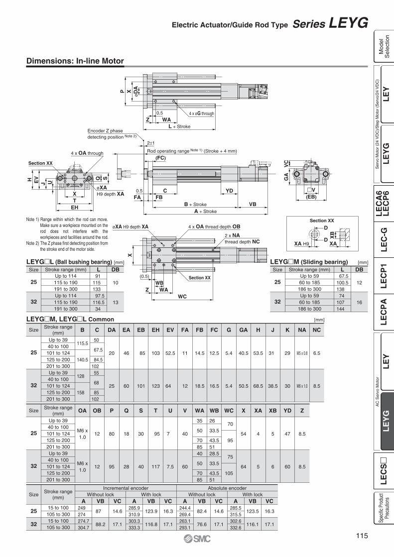
Section XX
XA H9
D
DXA
XB
4 x OA through
UJEVH G
AV
C
4 x øG throughZ WA
L + Stroke
0.5
øD
AXP
X
0.5
FA FBC YD
B + Stroke VBA + Stroke
V(EB)
Rod operating range Note 1) (Stroke + 4 mm)
2 1
Encoder Z phasedetecting position Note 2)
(FC)
(0.5)
ZWB
WAWC
Section XX
øXA H9 depth XA 4 x OA thread depth OB
2 x NAthread depth NC
EHTX
øXAH9 depth XA
Section XX
SQ
Dimensions: In-line Motor
[mm]
Stroke range (mm)Up to 114115 to 190191 to 300Up to 114115 to 190191 to 300
91115133 97.5116.5 34
10
13
Size
25
32
L DB
SizeIncremental encoder Absolute encoder
Without lock With lock Without lock With lockA VB VC A VB VC A VB VC A VB VC
LEYG L (Ball bushing bearing)
[mm]
Stroke range(mm)
Up to 3940 to 100101 to 124125 to 200201 to 300Up to 3940 to 100101 to 124125 to 200201 to 300
115.5
140.5
128
158
50
67.5
84.5102
55
68
85 102
20
25
46
60
85
101
103
123
52.5
64
11
12
14.5
18.5
12.5
16.5
5.4
5.4
40.5
50.5
53.5
68.5
31
38.5
29
30
M5 x 0.8
M6 x 1.0
6.5
8.5
Size
25
32
B C DA EA EB EH EV FA FB FC G GA H J K NA NC
Stroke range(mm)
Stroke range(mm)
Up to 3940 to 100101 to 124125 to 200201 to 300Up to 3940 to 100101 to 124125 to 200201 to 300
15 to 100105 to 30015 to 100105 to 300
70
95
75
105
35
50
708540
50
7085
26
33.5
43.551 28.5
33.5
43.551
18
28
80
95
12
12
M6 x1.0
M6 x1.0
30
40
95
117
7
7.5
40
60
54
64
4
5
5
6
47
60
8.5
8.5
Size
25
32
25
32
249274274.7304.7
87
88.2
14.6
17.1
285.9310.9303.3333.3
123.9
116.8
16.3
17.1
244.4269.4263.1293.1
82.4
76.6
14.6
17.1
285.5315.5302.6332.6
123.5
116.1
16.3
17.1
OA OB P Q S T U V WA WB WC X XA XB YD Z
LEYG M, LEYG L Common
[mm]
Stroke range (mm)Up to 5960 to 185
186 to 300Up to 5960 to 185186 to 300
67.5100.5138 74107144
12
16
Size
25
32
L DBLEYG M (Sliding bearing)
Note 1) Range within which the rod can move. Make sure a workpiece mounted on the rod does not interfere with the workpieces and facilities around the rod.
Note 2) The Z phase first detecting position from the stroke end of the motor side.
115
Electric Actuator/Guide Rod Type Series LEYG
LE
YL
EC
SL
EC
A6
LE
CP
6L
EC
-GL
EC
P1
LE
CP
AL
EY
GL
EY
LE
YG
Spec
ific P
rodu
ctPr
ecau
tions
AC
Ser
vo M
otor
Mod
elS
elec
tion
Ser
vo M
otor
(24
VD
C)/S
tep
Mot
or (S
ervo
/24
VD
C)

Support block
Body mounting bolt
2 x OA thread depth OB2 x øG through
X
WC + Stroke
ST(0.5)
EB
GA
Support block
Support Block
Guide for support block applicationWhen the stroke exceeds 100 mm and the lateral load is applied, the body will be bent based on the load. Mounting the support block is recommended. (Please order it separately from the models shown below.)
100st or less
101st or more, 300st or less
100st or less
101st or more, 300st or less
25
32
Size Stroke range EB G OA
12
12
M6 x 1.0
M6 x 1.0
5.4
5.4
85
101
OB
40.5
50.5
GA
70
95
75
105
WC
54
64
X
20
22
ST
LEYG-S025
LEYG-S032
Model
Two body mounting bolts are included with the support block.
Do not install the body using only a support block.The support block should be used only for support.
Caution
Support Block Model
LEYG S 025Size025032
For size 25For size 32
[mm]
116
Series LEYG

Design/Selection
Warning1. Do not apply a load in excess of the operating limit.
Select a suitable actuator by load and allowable lateral load on the rod end. If the product is used outside of the operating limit, the eccentric load applied to the piston rod will be excessive and have adverse effects such as creating play on the sliding parts of the piston rod, degrading accuracy and shortening the life of the product.
2. Do not use the product in applications where excessive external force or impact force is applied to it.This can cause failure.
3. Do not use as a stopper.
Handling
Caution1. When the pushing operation is used, be sure to set
to “Torque control mode”, and use within the specified pushing speed range for each series.Do not allow the piston rod to hit the workpiece and end of the stroke in the “Position control mode”, “Speed control mode” or “Positioning mode”. The lead screw, bearing and internal stopper may be damaged and lead to malfunction.
2. When operating with “Torque control mode”, the value of the internal torque command (LECSA) or the maximum output command for analog torque (LECSB) should be set 30% or less.It may lead to damage and malfunction.
3. The forward/reverse torque limit is set to 100% (3 times the motor rated torque) as default.This value is the maximum torque (the limit value) in the “Position control mode”, “Speed control mode” or “Positioning mode”. When the product is operated with a smaller value than the default, acceleration when driving can decrease. Set the value after confirming the actual device to be used.
4. The maximum speed of this actuator is affected by the product stroke.Check the model selection section of the catalog.
5. Do not apply a load, impact or resistance in addition to the transferred load during return to origin.Additional force will cause the displacement of the origin position.
6. Do not scratch or dent the sliding parts of the piston rod, by striking or attaching objects.The piston rod and guide rod are manufactured to precise tolerances, even a slight deformation may cause malfunction.
7. When an external guide is used, connect it in such a way that no impact or load is applied to it.Use a freely moving connector (such as a floating joint).
8. Do not operate by fixing the piston rod and moving the actuator body.Excessive load will be applied to the piston rod, leading to damage to the actuator and reduced the life of the product.
Handling
Wrench
Socket
Caution 9. When an actuator is operated with one end fixed
and the other free (ends tapped (standard), flange type), a bending moment may act on the actuator due to vibration generated at the stroke end, which can damage the actuator. In such a case, install a mounting bracket to suppress the vibration of the actuator body or reduce the speed so that the actuator does not vibrate.Also, use a mounting bracket when moving the actuator body or when a long stroke actuator is mounted horizontally and fixed at one end.
10. Avoid using the electric actuator in such a way that rotational torque would be applied to the piston rod.This may cause deformation of the non-rotating guide, abnormal responses of the auto switch, play in the internal guide or an increase in the sliding resistance.Refer to the table below for the approximate values of the allowable range of rotational torque.
When screwing in a bracket or nut to the end of the piston rod, hold the flats of the rod end with a wrench (the piston rod should be fully retracted). Do not apply tightening torque to the non-rotating mechanism.
Allowable rotationaltorque [N m] or less
LEY251.1
LEY321.4
Series LEY/LEYGElectric Actuators/Specific Product Precautions 1Be sure to read before handling. Refer to back cover for Safety Instructions and the Operation Manual for Electric Actuator Precautions.Please download it via our website, http://www.smcworld.com
11. When using auto switch with the guide rod type LEYG series, the following limits will be in effect. Please select the product while paying attention to this. Insert the auto switch from the front side with rod (plate) sticking out.
For the parts hidden behind the guide attachment (Rod stick out side), the auto switch cannot be fixed.
Consult with SMC when using auto switch on the rod stick out side.
Enclosure
First Characteristics:Degrees of protection against solid foreign objects
0123456
Non-protectedProtected against solid foreign objects of 50 mmø and greaterProtected against solid foreign objects of 12 mmø and greaterProtected against solid foreign objects of 2.5 mmø and greaterProtected against solid foreign objects of 1.0 mmø and greaterDust-protectedDust-tight
IPFirst characteristic numeral Second characteristic numeral
117
LE
YL
EC
SL
EC
A6
LE
CP
6L
EC
-GL
EC
P1
LE
CP
AL
EY
GL
EY
LE
YG
Spec
ific P
rodu
ctPr
ecau
tions
AC
Ser
vo M
otor
Mod
elS
elec
tion
Ser
vo M
otor
(24
VD
C)/S
tep
Mot
or (S
ervo
/24
VD
C)

Rod side Head side
Model
LEY25LEY32
M5 x 0.8M6 x 1.0
3.05.2
Bolt
6.58.8
Max. tighteningtorque (N m)
Max. screw-indepth (mm)
Model
LEY25LEY32
M5 x 0.8M6 x 1.0
3.05.2
Bolt
810
Max. tighteningtorque (N m)
Max. screw-indepth (mm)
Body fixed/Body bottom tapped style (When “Body bottom tapped” is selected.)
Body fixed/Rod side/Head side tapped style
Mounting
Caution
Maintenance
Warning1. Ensure that the power supply is stopped and the workpiece is removed
before starting maintenance work or replacement of the product. Maintenance frequencyPerform maintenance according to the table below.
Items for visual appearance check1. Loose set screws, Abnormal dirt2. Check of flaw and cable joint3. Vibration, Noise
Items for belt checkStop operation immediately and replace the belt when belt appear to be below. Further, ensure your operating environment and conditions satisfy the requirements specified for the product.a. Tooth shape canvas is worn out
Canvas fiber becomes fuzzy. Rubber is removed and the fiber becomes whitish. Lines of fibers become unclear.
b. Peeling off or wearing of the side of the beltBelt corner becomes round and frayed thread sticks out.
c. Belt partially cutBelt is partially cut. Foreign matter caught in teeth other than cut part causes flaw.
d. Vertical line of belt teethFlaw which is made when the belt runs on the flange.
e. Rubber back of the belt is softened and stickyf. Crack on the back of the belt
Inspection before daily operationInspection every 6 months/250 km/5 million cycles
Appearance check—
Belt checkFrequency
Select whichever comes sooner.
Except the LEY D.
Model Mounting position Flatness
LEY 0.1 mmor less
Body/Body bottom
3. Keep the flatness of the mounting surface within the following ranges when mounting the actuator body and workpiece.Unevenness of a workpiece or base mounted on the body of the product may cause an increase in the sliding resistance.
End socket
End bracketscrew-in depth
Rod end nut
Workpiece fixed/Rod end male thread (When “Rod end male thread” is selected.)
Model
LEY25LEY32
M14 x 1.5M14 x 1.5
65.065.0
Threadsize
20.520.5
1722
Max. tighteningtorque (N m)
Effective threadlength (mm)
End socket widthacross flats (mm)
Model
LEY25LEY32
8 or more8 or more
End bracketscrew-in depth (mm)
88
Length (mm)2222
Width across flats (mm)Rod end nut
Rod end nut is an accessory.
Mounting
Caution
End socket
1. When mounting workpieces or jigs to the piston rod end, hold the flats of the piston rod end with a wrench so that the piston rod does not rotate. The bolt should be tightened within the specified torque range.This may cause abnormal responses of the auto switch, play in the internal guide or an increase in the sliding resistance.
2. When mounting the product and/or workpiece, tighten the mounting screws within the specified torque range.Tightening with higher torque than the specified range may cause malfunction while the tightening with lower torque can cause the displacement of gripping position or dropping a workpiece.
Workpiece fixed/Rod end female thread
Model
LEY25LEY32
M8 x 1.25M8 x 1.25
12.512.5
Bolt
1313
1722
Max. tighteningtorque (N m)
Max. screw-indepth (mm)
End socket widthacross flats (mm)
Series LEY/LEYGElectric Actuators/Specific Product Precautions 2Be sure to read before handling. Refer to back cover for Safety Instructions and the Operation Manual for Electric Actuator Precautions.Please download it via our website, http://www.smcworld.com
Enclosure
Second Characteristics:Degrees of protection against water
0
1
2
3
4
5
6
7
8
Non-protected
Protected against vertically falling water drops
Protected against vertically falling water drops when enclosure tilted up to 15
Protected against rainfall when enclosure tilted up to 60
Protected against splashing water
Protected against water jets
Protected against powerful water jets
Protected against the effects of temporary immersion in waterProtected against the effects of continuous immersion in water
—
Dripprooftype 1Dripprooftype 2RainprooftypeSplashprooftypeWater-jet- proof typePowerful water-jet-proof typeImmersible typeSubmersible type
Example) In the case of stipulated as IP65, we can know the degrees of protection is dust-tight and water-jet-proof on the grounds that the first characteristic numeral is “6” and the second characteristic numeral is “5” respectively, that gives it will not be adversely affected by direct water jets from any direction.( The water jets which are “5” of the second characteristic numeral based on JIS C 0920 (2003) indicates a flow of water for 3 minutes at 12.5 L per minute.)
118

AC Servo Motor DriverSeries LECS
Pulse Input Type/Positioning Type
Pulse Input Type
Series LECSAIncremental Type
Series LECSBAbsoIute Type
CC-Link Direct Input Type
Series LECSCAbsolute Type
Series LECSSAbsolute Type
SSCNET III Type
119
LE
YL
EC
SL
EC
A6
LE
CP
6L
EC
-GL
EC
P1
LE
CP
AL
EY
GL
EY
LE
YG
Mod
elS
elec
tion
Ser
vo M
otor
(24
VD
C)/S
tep
Mot
or (S
ervo
/24
VD
C)
Spec
ific P
rodu
ctPr
ecau
tions
AC
Ser
vo M
otor

Series LECSA (Pulse input type/Positioning type)
Series LECS
Series LECSB (Pulse input type)
Series LECSC (CC-Link Direct Input Type)
Series LECSS (SSCNET III Type)
Position data/speed data setting and operation start/stop
Positioning by up to 255 point tables (when 2 stations occupied)
Up to 32 drivers connectable (when 2 stations occupied) with CC-Link communication
Applicable Fieldbus protocol: CC-Link (Ver. 1.10, max. communication speed: 10 Mbps)
Control encoder: Absolute 18-bit encoder (Resolution: 262144 pulse/rev)
Compatible with Mitsubishi Electric’s servo system controller network
Reduced wiring and SSCNET III optical cable for one-touch connection
SSCNET III optical cable provides enhanced noise resistance
Up to 16 drivers connectable with SSCNET III communication
Applicable Fieldbus protocol: SSCNET III (High-speed optical communication, max. bidirectional communication speed: 100 Mbps)
Control encoder: Absolute 18-bit encoder (Resolution: 262144 pulse/rev)
Up to 7 positioning points by point table
Input type: Pulse input
Control encoder: Incremental 17-bit encoder (Resolution: 131072 pulse/rev)
Parallel input: 6 inputsoutput: 4 outputs
Input type: Pulse input
Control encoder: Absolute 18-bit encoder (Resolution: 262144 pulse/rev)
Parallel input: 10 inputsoutput: 6 outputs
Incr
emen
tal T
ype
AC Servo Motor DriverA
bso
lute
Typ
ePower supply voltage 100 to 120 VAC
200 to 230 VAC
Motor capacity 100/200/400 W
120

How to Order
Series LECSB/LECSC/LECSSAbsolute TypeSeries LECSA (Pulse Input Type/Positioning Type)
Incremental TypeAC Servo Motor Driver
Dimensions
LECSA
LECSB
LECS 1A S1Driver type
Compatible motor type
Power supply voltage
TypeAC servo motor (S2)AC servo motor (S3)AC servo motor (S4)AC servo motor (S6)AC servo motor (S7)AC servo motor (S8)
Capacity100 W200 W400 W100 W200 W400 W
Encoder
Incremental
Absolute
Symbol
A
B
C
S
Pulse input type(For absolute encoder)
CC-Link direct input type(For absolute encoder)
SSCNET III type(For absolute encoder)
Pulse input type/Positioning type(For incremental encoder)
12
100 to 120 VAC, 50/60 Hz200 to 230 VAC, 50/60 Hz
6
5.5
5
130
120
40 1352 x ø6 Mounting hole(Bearing surface thickness 5)
Battery included.
ø6 Mounting hole(Bearing surface thickness 4)
CN3
CNP3
CNP2
CNP1
CN2
CN1
CN3
Battery
CN1
CN2
CN4
CN6CN5
CNP2
CNP1
(14)
156
66
6
161
168
40 135 (For LECSB -S5, S7)170 (For LECSB -S8)
LECSA LECSB LECSC LECSS
6
RoHS
Connector name DescriptionCN1CN2CN3CNP1CNP2
I/O signal connectorEncoder connectorUSB communication connectorMain circuit power supply connectorControl circuit power supply connector
Connector name Description
CN1CN2CN3CN4CN5CN6CNP1CNP2CNP3
I/O signal connectorEncoder connectorRS-422 communication connectorBattery connectorUSB communication connectorAnalog monitor connectorMain circuit power supply connectorControl circuit power supply connectorServo motor power connector
(Pulse Input Type) (CC-Link Direct Input Type) (SSCNET III Type)
Driver
S1 S3S4S5S7S8 Only available for power supply voltage “200 to 230 VAC”.
121
LE
YL
EC
SL
EC
A6
LE
CP
6L
EC
-GL
EC
P1
LE
CP
AL
EY
GL
EY
LE
YG
Mod
elS
elec
tion
Ser
vo M
otor
(24
VD
C)/S
tep
Mot
or (S
ervo
/24
VD
C)
Spec
ific P
rodu
ctPr
ecau
tions
AC
Ser
vo M
otor

Dimensions
LECSC
LECSS
Connector name DescriptionCN1CN2CN3CN4CN5CN6CNP1CNP2CNP3
CC-Link connectorEncoder connectorRS-422 communication connectorBattery connectorUSB communication connectorI/O signal connectorMain circuit power supply connectorControl circuit power supply connectorServo motor power connector
Connector name Description
CN1A
CN1B
CN2CN3CN4CN5CNP1CNP2CNP3
Encoder connectorI/O signal connectorBattery connectorUSB communication connectorMain circuit power supply connectorControl circuit power supply connectorServo motor power connector
Front axis connector forSSCNET III optical cable
Rear axis connector forSSCNET III optical cable
6
6
615
6
40135 (For LECSC -S5, S7)
170 (For LECSC -S8)
Battery included.
2 x ø6 Mounting hole(Bearing surface thickness 4)
CNP3
CNP2
CNP1
CN2CN4
Battery
Battery
CN6
CN1
CN3
CN5
168
6
6
615
6
40135 (For LECSS -S5, S7)
170 (For LECSS -S8)
Battery included.
2 x ø6 Mounting hole(Bearing surface thickness 4)
CNP3
CNP2
CNP1
CN2
CN4
CN1B
CN1A
CN3
CN5
168
122
Series LECS
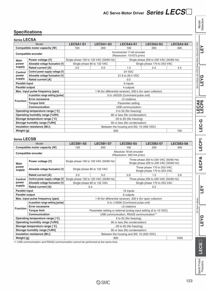
Specifications
ModelCompatible motor capacity [W]
Compatible encoder
Power voltage [V]Allowable voltage fluctuation [V]Rated current [A]Control power supply voltage [V]Allowable voltage fluctuation [V]Rated current [A]
In-position range setting [pulse]Error excessiveTorque limitCommunication
Parallel inputParallel outputMax. input pulse frequency [pps]
Operating temperature range [ C]Operating humidity range [%RH]Storage temperature range [ C]Storage humidity range [%RH]Insulation resistance [M ]Weight [g]
Mainpowersupply
Function
Controlpowersupply
LECSA1-S1100
3.0
LECSA1-S3200
5.0
Single phase 100 to 120 VAC (50/60 Hz)Single phase 85 to 132 VAC
LECSA2-S1100
1.524 VDC
21.6 to 26.4 VDC0.5
6 inputs4 outputs
1 M (for differential receiver), 200 k (for open collector)0 to 65535 (Command pulse unit)
3 rotationsParameter setting
USB communication0 to 55 (No freezing)
90 or less (No condensation)20 to 65 (No freezing)
90 or less (No condensation)Between the housing and SG: 10 (500 VDC)
LECSA2-S3200
2.4
Single phase 200 to 230 VAC (50/60 Hz)Single phase 170 to 253 VAC
Incremental 17-bit encoder(Resolution: 131072 p/rev)
Series LECSA
Series LECSBModel LECSB1-S5 LECSB1-S7 LECSB2-S5 LECSB2-S7 LECSB2-S8
Compatible motor capacity [W]
Compatible encoder
Power voltage [V]
Allowable voltage fluctuation [V]
Rated current [A]Control power supply voltage [V]Allowable voltage fluctuation [V]Rated current [A]
In-position range setting [pulse]Error excessiveTorque limitCommunication
Parallel inputParallel outputMax. input pulse frequency [pps]
Operating temperature range [ C]Operating humidity range [%RH]Storage temperature range [ C]Storage humidity range [%RH]Insulation resistance [M ]Weight [g]
Mainpowersupply
Function
Controlpowersupply
100 200 100 400200
3.0 5.0
Single phase 100 to 120 VAC (50/60 Hz)
Single phase 85 to 132 VAC
0.9
10 inputs6 outputs
1 M (for differential receiver), 200 k (for open collector)0 to 10000 (Command pulse unit)
3 rotationsParameter setting or external analog input setting (0 to 10 VDC)
USB communication, RS422 communication 1
0 to 55 (No freezing)90 or less (No condensation)
20 to 65 (No freezing)90 or less (No condensation)
Between the housing and SG: 10 (500 VDC)
Single phase 100 to 120 VAC (50/60 Hz)Single phase 85 to 132 VAC
0.4
Three phase 200 to 230 VAC (50/60 Hz)Single phase 170 to 253 VAC
0.2
2.61.5
1000800
Three phase 200 to 230 VAC (50/60 Hz)Single phase 200 to 230 VAC (50/60 Hz)
Three phase 170 to 253 VACSingle phase 170 to 253 VAC
Absolute 18-bit encoder(Resolution: 262144 p/rev)
1 USB communication and RS422 communication cannot be performed at the same time.
600
LECSA2-S4400
4.5
700
123
AC Servo Motor Driver Series LECS
LE
YL
EC
SL
EC
A6
LE
CP
6L
EC
-GL
EC
P1
LE
CP
AL
EY
GL
EY
LE
YG
Mod
elS
elec
tion
Ser
vo M
otor
(24
VD
C)/S
tep
Mot
or (S
ervo
/24
VD
C)
Spec
ific P
rodu
ctPr
ecau
tions
AC
Ser
vo M
otor
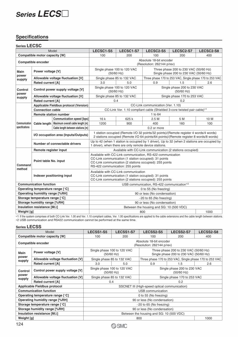
Specifications
ModelCompatible motor capacity [W]
Compatible encoder
Power voltage [V]
Allowable voltage fluctuation [V]Rated current [A]
Control power supply voltage [V]
Allowable voltage fluctuation [V]Rated current [A]Applicable Fieldbus protocol (Version)Connection cableRemote station number
Cable length
I/O occupation area (Inputs/Outputs)
Number of connectable drivers
Remote register input
Point table No. input
Indexer positioning input
LECSC1-S5100
Single phase 85 to 132 VAC
LECSC1-S7200
Single phase 100 to 120 VAC(50/60 Hz)
Single phase 100 to 120 VAC(50/60 Hz)
Single phase 85 to 132 VAC0.4
Single phase 200 to 230 VAC(50/60 Hz)
Single phase 170 to 253 VAC0.2
LECSC2-S5100
Three phase 170 to 253 VAC, Single phase 170 to 253 VAC0.9
USB communication, RS-422 communication 2
0 to 55 (No freezing)90 or less (No condensation)
20 to 65 (No freezing)90 or less (No condensation)
Between the housing and SG: 10 (500 VDC)
CC-Link communication (Ver. 1.10)CC-Link Ver. 1.10 compliant cable (Shielded 3-core twisted pair cable) 1
1 to 64
0.2 or more
Available with CC-Link communication (2 stations occupied)
Available with CC-Link communication, RS-422 communicationCC-Link communication (1 station occupied): 31 points CC-Link communication (2 stations occupied): 255 pointsRS-422 communication: 255 points
Available with CC-Link communicationCC-Link communication (1 station occupied): 31 points CC-Link communication (2 stations occupied): 255 points
1 station occupied (Remote I/O 32 points/32 points)/(Remote register 4 words/4 words)2 stations occupied (Remote I/O 64 points/64 points)/(Remote register 8 words/8 words)
3.0 5.0
800 1000
1.5 2.6
2.5 M400
16 k1200
625 k900
5 M160
10 M100
LECSC2-S7200
LECSC2-S8400
Three phase 200 to 230 VAC (50/60 Hz)Single phase 200 to 230 VAC (50/60 Hz)
Absolute 18-bit encoder(Resolution: 262144 p/rev)
Series LECSC
1 If the system comprises of both CC-Link Ver. 1.00 and Ver. 1.10 compliant cables, Ver. 1.00 specifications are applied to the cable extensions and the cable length between stations.2 USB communication and RS422 communication cannot be performed at the same time.
Controlpowersupply
Commandmethod
Mainpowersupply
Communicationspecifications
Communication speed [bps]Maximum overall cable length [m]Cable length between stations [m]
ModelCompatible motor capacity [W]
Compatible encoder
Applicable Fieldbus protocolCommunication functionOperating temperature range [ C]Operating humidity range [%RH]Storage temperature range [ C]Storage humidity range [%RH]Insulation resistance [M ]Weight [g]
Power voltage [V]
Allowable voltage fluctuation [V]Rated current [A]
Control power supply voltage [V]
Allowable voltage fluctuation [V]Rated current [A]
LECSS1-S5100
Single phase 85 to 132 VAC
LECSS1-S7200
Single phase 100 to 120 VAC(50/60 Hz)
Single phase 100 to 120 VAC(50/60 Hz)
Single phase 200 to 230 VAC(50/60 Hz)
Single phase 85 to 132 VAC0.4
Single phase 170 to 253 VAC0.2
LECSS2-S5100
Three phase 170 to 253 VAC, Single phase 170 to 253 VAC0.9
SSCNET III (High-speed optical communication)USB communication0 to 55 (No freezing)
90 or less (No condensation)20 to 65 (No freezing)
90 or less (No condensation)Between the housing and SG: 10 (500 VDC)
3.0 5.0
1000
1.5 2.6
LECSS2-S7200
LECSS2-S8400
Three phase 200 to 230 VAC (50/60 Hz)Single phase 200 to 230 VAC (50/60 Hz)
Absolute 18-bit encoder(Resolution: 262144 p/rev)
Series LECSS
Controlpowersupply
Mainpowersupply
800
Communication functionOperating temperature range [ C]Operating humidity range [%RH]Storage temperature range [ C]Storage humidity range [%RH]Insulation resistance [M ]Weight [g]
Up to 42 (when 1 station is occupied by 1 driver), Up to 32 (when 2 stations are occupied by 1 driver), when there are only remote device stations.
124
Series LECS

Power Supply Wiring Example: LECSA
LECSA -
Main Circuit Power Supply Connector: CNP1Terminal name Function Details
L1 L1
L2
P
C
U
V
W
24V
0V
L2
P
C
UVW
Main circuitpower supply
Regeneration option
Servo motor power (U)Servo motor power (V)Servo motor power (W)
Protective earth (PE)
Connect the main circuit power supply.LECSA1: Single phase 100 to 120 VAC, 50/60 HzLECSA2: Single phase 200 to 230 VAC, 50/60 Hz
Terminal to connect regeneration optionLECSA -S1: Not connected at time of shipping.LECSA -S3, S4: Connected at time of shipping. If regeneration option is required for “Model Selection”,connect to this terminal.
Connect to motor cable (U, V, W).
Should be grounded by connecting the servo motor’s earthterminal and the control panel’s protective earth (PE).
Terminal name Function Details
24V
0V
Control circuitpower supply (24 V)
24 V side of the control circuit power supply (24 VDC)supplied to the driver
Accessory
Control Circuit Power Supply Connector: CNP2 Accessory
Main circuit power supplySingle phase 200 to 230 VACorSingle phase 100 to 120 VAC
Control circuit power supply24 VDC
L1
CNP1NFB MCBuilt-in
regenerativeresistor
Regeneration option
CN2
L2
P
U
V
W
U MotorV
WM
C
+24V
CNP2
0V
DetectorCircuit protector
0 V side of the control circuit power supply (24 VDC) supplied to the driver
Control circuitpower supply (0 V)
125
AC Servo Motor Driver Series LECS
LE
YL
EC
SL
EC
A6
LE
CP
6L
EC
-GL
EC
P1
LE
CP
AL
EY
GL
EY
LE
YG
Mod
elS
elec
tion
Ser
vo M
otor
(24
VD
C)/S
tep
Mot
or (S
ervo
/24
VD
C)
Spec
ific P
rodu
ctPr
ecau
tions
AC
Ser
vo M
otor

Main Circuit Power Supply Connector: CNP1Terminal name Function Details
L1
L2
L3
NP1
P2
Main circuitpower supply
Connect the main circuit power supply.LECSB1/LECSC1/LECSS1: Single phase 100 to 120 VAC, 50/60 Hz Connection terminal: L1,L2
LECSB2/LECSC2/LECSS2: Single phase 200 to 230 VAC, 50/60 Hz Connection terminal: L1,L2
Three phase 200 to 230 VAC, 50/60 Hz Connection terminal: L1,L2,L3
Do not connect.
Connect between P1 and P2. (Connected at time of shipping.)
Accessory
Power Supply Wiring Example: LECSB, LECSC, LECSS
LECSB1-LECSC1-LECSS1-
LECSB2-LECSC2-LECSS2-
For three phase 200 VAC
Threephase200 to 230VAC
L1
CNP1NFB MCCNP3
PE
CN2
L2
P1
P2
L3
U
V
W
U MotorV
WM
N( )
P(+)
CNP2
C
L21
D
L11
For single phase 200 VAC
Note) For single phase 200 to 230 VAC, power supply should be connected to L1 and L2 terminals, with nothing connected to L3.
Detector
Singlephase200 to 230VAC
L1
CNP1NFB MCCNP3
PE
CN2
L2
P1
P2
L3
U
V
W
U MotorV
WM
N
P
CNP2
C
L21
D
L11Detector
Single phase100 to 120 VAC
L1
CNP1NFB MCCNP3
PE
CN2
Open
P1
P2
L2
U
V
W
U MotorV
WM
N
P
CNP2
C
L21
D
L11Detector
Regeneration option
Regeneration optionRegeneration option
PCD
L11
L21
Regenerationoption
Control circuitpower supply
Terminal name Function Details
Control Circuit Power Supply Connector: CNP2 Accessory
Connect the control circuit power supply.LECSB1/LECSC1/LECSS1: Single phase 100 to 120 VAC, 50/60 Hz Connection terminal: L11,L21
LECSB2/LECSC2/LECSS2: Single phase 200 to 230 VAC, 50/60 Hz Connection terminal: L11,L21
Three phase 200 to 230 VAC, 50/60 Hz Connection terminal: L11,L21
UVW
Servo motor power (U)Servo motor power (V)Servo motor power (W)
Connect to motor cable (U, V, W).
Terminal name Function Details
Motor Connector: CNP3 Accessory
L1
L2
L3
N
P1
P2
P
C
D
L11
L21
U
V
W
LECSBFront viewexample
Connect between P and D. (Connected at time of shipping.) If regeneration option is required for “Model Selection”, connect to this terminal.
126
Series LECS

Control Signal Wiring Example: LECSA
Note 1) For preventing electric shock, be sure to connect the driver circuit power supply connector (CNP1)’s protective earth (PE) terminal to the control panel’s protective earth (PE).
Note 2) For interface use, supply 24 VDC 10% 200 mA using an external source. 200 mA is the value when all I/O command signals are used and reducing the number of inputs/outputs can decrease current capacity. Refer to “Operation Manual” for required current for interface.
Note 3) The failure (ALM) is ON during normal conditions. When it is OFF (alarm occurs), stop the sequencer signal using the sequence program.Note 4) The same name signals are connected inside the driver.Note 5) For command pulse input with an open collector method. When a positioning unit loaded with a differential line driver method is used, it is 10 m or
less.
FX3U- MT/ES (Manufactured by Mitsubishi Electric)PLC
CNP1
Sequencerpowersupply
PE
S/S
24V
0V
L
N
S/SY000
COM1
Y010
COM3
COM2
X
X
X
Y004
LECSA
24 VDC
CN1
DICOM
OPC
DOCOM
PP
NP
CR
RD
LG
SD
INP
OP
Note 4)
Note 4)
Note 2)CN1
CN1
10 m or less
2 m or less Note 5)
10 m or less
Note 1)
1
2
13
23
25
5
11
14
Plate
10
21
9
12
15
Plate
20
ALM
EM1Forced stop
Servo ON
Reset
Forward rotation stroke end
Reverse rotation stroke end
8
SON 4
RES 3
LSP 6
LSN 7
MBR
LA
16 LAR
17 LB
18 LBR
19 LZ
SD
LZR
14 LG
Failure Note 3)
Electromagneticbrake interlock
A-phase pulse detector(Differential line driver)
B-phase pulse detector(Differential line driver)
Z-phase pulse detector(Differential line driver)
Control common
RA1
RA2
This wiring example shows connection with a PLC (FX3U- MT/ES) manufactured by Mitsubishi Electric as when used in position control mode. Refer to the LECSA operation manual and any technical literature or operation manuals for your PLC and positioning unit before connecting to another PLC or positioning unit.
Note 4)
127
AC Servo Motor Driver Series LECS
LE
YL
EC
SL
EC
A6
LE
CP
6L
EC
-GL
EC
P1
LE
CP
AL
EY
GL
EY
LE
YG
Mod
elS
elec
tion
Ser
vo M
otor
(24
VD
C)/S
tep
Mot
or (S
ervo
/24
VD
C)
Spec
ific P
rodu
ctPr
ecau
tions
AC
Ser
vo M
otor

Control Signal Wiring Example: LECSB
Note 1) For preventing electric shock, be sure to connect the driver circuit power supply connector (CNP1)’s protective earth (PE) terminal to the control panel’s protective earth (PE).
Note 2) For interface use, supply 24 VDC 10% 300 mA using an external source.Note 3) The failure (ALM) is ON during normal conditions. When it is OFF (alarm occurs), stop the sequencer signal using the sequence program.Note 4) The same name signals are connected inside the driver.Note 5) For command pulse input with a differential line driver method. For open collector method, it is 2 m or less.
Positioning unitQD75D (Manufactured by
Mitsubishi Electric)
PE
CLEARCOM
CLEAR
RDYCOM
READY
PULSE F+
PULSE F
S/S
PG0
PG0 COM
LECSB
24 VDC Note 2)
CN1
DICOM
DOCOM
CR
PP
NG
LG
LZ
SD
Note 4)
CN1Note 4)
Note 4)
Note 4)
CN1
CN6
2 m or less
10 m or less
10 m or less Note 5)
2 m or less
10 m or less
Note 1)
20
46
41
10
PG 11
NP 35
36
3
LZR 9
8
Plate
21
48
Plate
33
DICOM
EMGEmergency stop
Servo ON
Reset
Proportion control
External torque limit selection
Forward rotation stroke end
Reverse rotation stroke end
Analog torque limit+10 V/Maximum torque
Upper limit setting
42
SON 15
RES 19
PC 17
TL 18
LSP 43
LSN 44
DOCOM 47
P15R 1
TLA 27
LG 28
SD Plate
ALM
23 ZSP
25 TLC
24 INP
4 LA
5 LAR
6 LB
7 LBR
SD
OP
34 LG
1 P15R
Failure Note 3)
Zero speed detection
Torque limiting
Positioning completion
A-phase pulse detector(Differential line driver)
B-phase pulse detector(Differential line driver)
Z-phase pulse detector(Open collector)
Control common
Control common
RA1
RA2
RA3
2 m or less
1 LG
3 MO1
2 MO2 Analog monitor 2
Analog monitor 1
10 VDC
10 VDC
RA4
PULSE R+
PULSE R
14
13
12
11
15
16
10
9
17
18
RD 49
This wiring example shows connection with a positioning unit (QD75D) manufactured by Mitsubishi Electric as when used in position control mode. Refer to the LECSB operation manual and any technical literature or operation manuals for your PLC and positioning unit before connecting to another PLC or positioning unit.
128
Series LECS

Control Signal Wiring Example: LECSC
Note 1) For preventing electric shock, be sure to connect the driver’s protective earth (PE) terminal (marked ) to the control panel’s protective earth (PE).Note 2) For interface use, supply 24 VDC 10% 150 mA using an external source.Note 3) The failure (ALM) is ON during normal conditions. When it is OFF (alarm occurs), stop the sequencer signal using the sequence program.
PE
CN6
LECSC
CN6
10 m or less
10 m or less
Note 1)
14
15
Plate
25
RD
DICOM
Forced stop
Proximity dog
Forward rotation stroke end
Reverse rotation stroke end
5
DOCOM 17
EMG 1
DOG 2
LSP 3
LSN 4
ALM
16 ZP
13 LZ
26 LZR
11 LA
24 LAR
SD
LBR
12 LB
23 LG
Ready
Failure Note 3)
Home position return completion
Z-phase pulse detector(Differential line driver)
A-phase pulse detector(Differential line driver)
B-phase pulse detector(Differential line driver)
Control common
RA1
RA2
RA3
Note 2)
+
CN1
CC-Link
24 VDCPowersupply
129
AC Servo Motor Driver Series LECS
LE
YL
EC
SL
EC
A6
LE
CP
6L
EC
-GL
EC
P1
LE
CP
AL
EY
GL
EY
LE
YG
Mod
elS
elec
tion
Ser
vo M
otor
(24
VD
C)/S
tep
Mot
or (S
ervo
/24
VD
C)
Spec
ific P
rodu
ctPr
ecau
tions
AC
Ser
vo M
otor

Note 1) For preventing electric shock, be sure to connect the driver’s protective earth (PE) terminal (marked ) to the control panel’s protective earth (PE).
Note 2) For interface use, supply 24 VDC 10% 150 mA using an external source.
Note 3) The failure (ALM) is ON during normal conditions.When it is OFF (alarm occurs), stop the sequencer signal using the sequence program.
Note 4) The same name signals are connected inside the driver.
Note 5) Use the following SSCNET III optical cables. Refer to “SSCNET III optical cable” on page 131 for cable models.
Note 6) Connections from Axis 2 onward are omitted.Note 7) Up to 16 axes can be set.Note 8) Be sure to place a cap on unused CN1A/CN1B.
PE
LECSS
LECSS
CN3Note 4)
CN3
10 m or less 10 m or less
Note 4)
Note 1)
Note 6)
Note 7)
Note 7)
Note 6)
Note 7)
Note 6)
Note 7)
13
9
4
11
MBRDICOM
Forced stop
Upper stroke limit (FLS)
Lower stroke limit (RLS)
Proximity dog (DOG)
5
D0COM 3
EM1 20
D11 2
D12 12
D13 19
INP
15 ALM
10 DICOM
6 LA
16 LAR
7 LB
17 LBR
8 LZ
MO1
1 LG
14 MO2
Plate SD
LG
18 LZR
Electromagnetic brake interlock Note 2)
In position
Failure Note 3)
A-phase pulse detector(Differential line driver)
SSCNET III optical cable Note 5)
(Option)
SSCNET III optical cable Note 5)
(Option)
Cap Note 8)
Servo systemcontroller
B-phase pulse detector(Differential line driver)
Z-phase pulse detector(Differential line driver)
Control common
Analog monitor 1
Analog monitor 2
SW1
SW2
(Axis 2)
1 2
SW1
SW2
1 2
RA2
RA3
2 m or less
Control Signal Wiring Example: LECSS
CN1A
CN1B
CN1A
CN1B
CN1A
CN1B
CN1A
CN1B
RA1
Cable Cable lengthCable modelLE-CSS-SSCNET III optical cable 0.15 m to 3 m
LECSS(Axis 3)
SW1
SW2
1 2
LECSS(Axis n)
SW1
SW2
1 2
24 VDCNote 2)
130
Series LECS

Options
Motor cable, Lock cable, Encoder cable (LECS common)
Cable type
Cable descriptionMBE
Motor cableLock cable
Encoder cable
Motor typeS AC servo motor
SR
Standard cableRobotic cable
Cable length (L) [m]25A
2510
LE CS M S 5 A
1
LE-CSS- is MR-J3BUS Mmanufactured by Mitsubishi Electric.
LKJ13
0.15 m0.3 m0.5 m1 m3 m
Cable length
SSCNET III optical cable
LE CSS
S AC servo motor
Motor type
S SSCNET III optical cable
Cable description
LE-CSM-S is MR-PWS1CBL M-A -L manufactured by Mitsubishi Electric.LE-CSB-S is MR-BKS1CBL M-A -L manufactured by Mitsubishi Electric.LE-CSE-S is MR-J3ENCBL M-A -L manufactured by Mitsubishi Electric.LE-CSM-R is MR-PWS1CBL M-A -H manufactured by Mitsubishi Electric.LE-CSB-R is MR-BKS1CBL M-A -H manufactured by Mitsubishi Electric.LE-CSE-R is MR-J3ENCBL M-A -H manufactured by Mitsubishi Electric.
I/O connector
LE-CSNA
ABS
Driver type
03212
Allowable regenerative power 30 WAllowable regenerative power 100 W
Model
Regeneration option type
LE-CSNB LE-CSNS
Regeneration option (LECS common)
LEC MR RB
LE CSN A
LEC-MR-RB-032LEC-MR-RB-12
LA3040
LB119169
LC 99149
LD1.62
Dimensions [mm]
Confirm regeneration option to be used in “Model Selection”.
MR-RB- manufactured by Mitsubishi Electric.
LE-CSNA: 10126-3000PE (connector)/10326-52F0-008 (shell kit) manufactured by 3M or equivalent item.LE-CSNB: 10150-3000PE (connector)/10350-52F0-008 (shell kit) manufactured by 3M or equivalent item.LE-CSNS: 10120-3000PE (connector)/10320-52F0-008 (shell kit) manufactured by 3M or equivalent item.
LECSA , LECSCLECSBLECSS
LE-CSM- : Motor cable
LE-CSB- : Lock cable
LE-CSE- : Encoder cable
(30) L
L(29.6)
(11.
8)(1
3)
(30) L 37.4
18.8
33.3
39
52.4
3939
37.2
168
156
LA
144
LCLB
15
(13.
7)
ø6 Mounting hole
(6)
6
5
LD12
6
(12)
(20)
Direction of connector
A
B
Counter axis side
Axis side
131
AC Servo Motor Driver Series LECS
LE
YL
EC
SL
EC
A6
LE
CP
6L
EC
-GL
EC
P1
LE
CP
AL
EY
GL
EY
LE
YG
Mod
elS
elec
tion
Ser
vo M
otor
(24
VD
C)/S
tep
Mot
or (S
ervo
/24
VD
C)
Spec
ific P
rodu
ctPr
ecau
tions
AC
Ser
vo M
otor

Options
USB cable (3 m) Battery (only for LECSB, LECSC or LECSS)
LEC MR J3USB LEC MR J3BAT
Compatible PC
Hardware Requirements
When using setup software (MR Configurator™), use an IBM PC/AT compatible PC that meets the following operating conditions.
Cable for connecting PC and driver when using the setupsoftware (MR Configurator™).Do not use any cable other than this cable.
Equipment
Note 1) Note 2) Note 3)
PC
Available HD space
Communication interface
OS
Display
Setup software (MR Configurator™)LEC-MR-SETUP221
Keyboard
Mouse
Printer
USB cable
Setup software (MR Configurator™) (LECSA, LECSB, LECSC, LECSS common)
LEC MR SETUP221
MRZJW3-SETUP221 manufactured by Mitsubishi Electric.Refer to Mitsubishi Electric’s website for operating environment and version update information.MR Configurator™ is a registered trademark or trademark of Mitsubishi Electric.
MR-J3BAT manufactured by Mitsubishi Electric. MR-J3USB manufactured by Mitsubishi Electric.
The connectable with the above PC
The connectable with the above PC
The connectable with the above PC
LEC-MR-J3USB Note 4, 5)
130 MB or more
Use USB port
Resolution 1024 x 768 or moreMust be capable of high color (16-bit) display.
The connectable with the above PC
Drivers
USB cable
PC Setup software(MR Configurator™)LECSA LECSB LECSC LECSS
Display language
EJapanese versionEnglish version
Nil
Battery for replacement.Absolute position data is maintained by installing the battery to the driver.
Windows®98, Windows®Me, Windows®2000 Professional,Windows®XP Professional / Home Edition,Windows Vista® Home Basic / Home Premium / Business / Ultimate / EnterpriseWindows®7 Starter / Home Premium / Professional / Ultimate / Enterprise
Adjustment, waveform display, diagnostics, parameter read/write, and test operation can be performed upon a PC.
Note 1) Before using a PC for setting LECSA point table method/program method or LECSC point table No. input, upgrade to version C5 (Japanese version) /version C4 (English version). Refer to Mitsubishi Electric’s website for version upgrade information.
Note 2) Windows, Windows Vista, Windows 7 are registered trademarks of Microsoft Corporation in the United States and/or other countries.Note 3) This software may not run correctly depending on the PC that you are using.Note 4) Not compatible with 64-bit Windows® XP and 64-bit Windows Vista®.Note 5) Order USB cable separately.
132
Series LECS

Be sure to read before handling. Refer to back cover for Safety Instructions and the Operation Manual for Electric Actuator Precautions.Please download it via our website, http://www.smcworld.com
Design/Selection
Warning1. Use the specified voltage.
If the applied voltage is higher than the specified voltage, malfunction and damage to the driver may result. If the applied voltage is lower than the specified voltage, there is a possibility that the load cannot be moved due to internal voltage drop. Check the operating voltage prior to start. Also, confirm that the operating voltage does not drop below the specified voltage during operation.
2. Do not use the products outside the specifications.Otherwise, fire, malfunction or damage to the driver/actuator can result. Check the specifications prior to use.
3. Install an emergency stop circuit.Install an emergency stop outside the enclosure in easy reach to the operator so that the operator can stop the system operation immediately and intercept the power supply.
4. To prevent danger and damage due to a breakdown or malfunction of these products, which may occur at a certain probability, a backup system should be arranged in advance by using a multiple-layered structure or by making a fail-safe equipment design, etc.
5. If there is a risk of fire or personal injury due to abnormal heat generation, sparking, smoke generated by the product, etc., cut off the power supply from this product and the system immediately.
Handling
Warning1. Never touch the inside of the driver and its peripheral
devices.Otherwise, electric shock or failure can result.
2. Do not operate or set up this equipment with wet hands.Otherwise, electric shock can result.
3. Do not use a product that is damaged or missing any components.Electric shock, fire or injury can result.
4. Use only the specified combination between the electric actuator and driver.Otherwise, it may cause damage to the driver or to the other equipment.
5. Be careful not to touch, get caught or hit by the workpiece while the actuator is moving.An injury can result.
6. Do not connect the power supply or power up the product until it is confirmed that the workpiece can be moved safely within the area that can be reached by the workpiece.Otherwise, the movement of the workpiece may cause an accident.
7. Do not touch the product when it is energized and for some time after the power has been disconnected, as it is very hot.Otherwise, it may cause burns due to the high temperature.
8. Check the voltage using a tester at least 5 minutes after power-off when performing installation, wiring and maintenance.Otherwise, electric shock, fire or injury can result.
Handling
Warning9. Static electricity may cause a malfunction or damage
the driver. Do not touch the driver while power is supplied to it.Take sufficient safety measures to eliminate static electricity when it is necessary to touch the driver for maintenance.
10. Do not use the products in an area where they could be exposed to dust, metallic powder, machining chips or splashes of water, oil or chemicals.Otherwise, a failure or malfunction can result.
11. Do not use the products in a magnetic field.Otherwise, a malfunction or failure can result.
12. Do not use the products in an environment where flammable, explosive or corrosive gases, liquids or other substances are present.Otherwise, fire, explosion or corrosion can result.
13. Avoid heat radiation from strong heat sources, such as direct sunlight or a hot furnace.Otherwise, it will cause a failure to the driver or its peripheral devices.
14. Do not use the products in an environment with cyclic temperature changes.Otherwise, it will cause a failure to the driver or its peripheral devices.
15. Do not use the products in an environment where surges are generated.Devices (solenoid type lifters, high frequency induction furnaces, motors, etc.) that generate a large amount of surge around the product may lead to deterioration or damage to the internal circuits of the products. Avoid supplies of surge generation and crossed lines.
16. Do not install these products in a place subject to vibration and impact.Otherwise, a malfunction or failure can result.
17. When a surge generating load such as a relay or solenoid valve is directly driven, use a product that incorporates a surge absorption element.
Mounting
Warning1. Install the driver and its peripheral devices on fireproof
material.Direct installation on or near flammable material may cause fire.
2. Do not install these products in a place subject to vibration and impact.Otherwise, a malfunction or failure can result.
3. The driver should be mounted on a vertical wall in a vertical direction.Also, do not cover the driver’s suction/exhaust ports.
4. Install the driver and its peripheral devices on a flat surface.If the mounting surface is not flat or uneven, excessive force may be applied to the housing and other parts resulting in a malfunction.
Series LECSSpecific Product Precautions 1
133
LE
YL
EC
SL
EC
A6
LE
CP
6L
EC
-GL
EC
P1
LE
CP
AL
EY
GL
EY
LE
YG
Spec
ific P
rodu
ctPr
ecau
tions
AC
Ser
vo M
otor
Mod
elS
elec
tion
Ser
vo M
otor
(24
VD
C)/S
tep
Mot
or (S
ervo
/24
VD
C)

Grounding
Warning1. For grounding actuator, connect the copper wire of
the actuator to the driver’s protective earth (PE) terminal and connect the copper wire of the driver to the earth via the control panel’s protective earth (PE) terminal.Do not connect them directly to the control panel’s protective earth (PE) terminal.
2. In the unlikely event that malfunction is caused by the ground, it may be disconnected.
Driver
Control panel
PE terminal Actuator
Maintenance
Warning1. Perform maintenance checks periodically.
Confirm wiring and screws are not loose. Loose screws or wires may cause unexpected malfunction.
2. Conduct an appropriate functional inspection and test after completed maintenance.In case of any abnormalities (if the actuator does not move or the equipment does not operate properly, etc.), stop the operation of the system. Otherwise, unexpected malfunction may occur and safety cannot be assured. Conduct a test of the emergency stop to confirm the safety of the equipment.
3. Do not disassemble, modify or repair the driver or its peripheral devices.
4. Do not put anything conductive or flammable inside the driver.Otherwise, fire can result.
5. Do not conduct an insulation resistance test or insulation withstand voltage test.
6. Reserve sufficient space for maintenance.Design the system so that it allows required space for maintenance.
Power Supply
Caution1. Use a power supply with low noise between lines and
between power and ground.In cases where noise is high, use an isolation transformer.
2. Take appropriate measures to prevent surges from lightning. Ground the surge absorber for lightning separately from the grounding of the driver and its peripheral devices.
Wiring
Warning1. The driver will be damaged if a commercial power
supply (100V/200V) is added to the driver,s servo motor
power (U, V, W). Be sure to check wiring such as wiring mistakes when the power supply is turned on.
2. Connect the ends of the U, V, W wires from the motor cable correctly to the phases (U, V, W) of the servo motor power. If these wires do not match up, it is unable to control the servo motor.
Series LECSSpecific Product Precautions 2Be sure to read before handling. Refer to back cover for Safety Instructions and the Operation Manual for Electric Actuator Precautions.Please download it via our website, http://www.smcworld.com
134


Addition of in-line motor type, LEY D seriesAddition of guide rod type, LEYG seriesAddition of guide rod type/in-line motor type, LEYG D seriesAddition of programless controller, LECP1 seriesAddition of standard cable to actuator cable type Addition of AC servo motor (100/200 W) type, LEY S seriesAddition of AC servo motor driver, LECSA/LECSB seriesNumber of pages from 40 to 96 PY
Addition of size 40 to step motor (servo/24 VDC) LEY/LEYG seriesAddition of size 63 to AC servo motor rod type LEY seriesAddition of dust/drip proof specification to rod type Addition of size 25, 32 AC servo motor guide rod type, LEYG seriesAddition of step motor driver, LECPA series Addition of gateway unit, LEC-G seriesAddition of AC servo motor driver, LECSC/LECSS seriesAddition of UL compliantChange of controller setting kit, LEC-W2 seriesNumber of pages from 96 to 160 RP
Revision history
Edition C
Edition D

1. The compatibility of the product is the responsibility of the person who designs the equipment or decides its specifications.Since the product specified here is used under various operating conditions, its compatibility with specific equipment must be decided by the person who designs the equipment or decides its specifications based on necessary analysis and test results. The expected performance and safety assurance of the equipment will be the responsibility of the person who has determined its compatibility with the product. This person should also continuously review all specifications of the product referring to its latest catalog information, with a view to giving due consideration to any possibility of equipment failure when configuring the equipment.
2. Only personnel with appropriate training should operate machinery and equipment.The product specified here may become unsafe if handled incorrectly. The assembly, operation and maintenance of machines or equipment including our products must be performed by an operator who is appropriately trained and experienced.
3. Do not service or attempt to remove product and machinery/equipment until safety is confirmed.1. The inspection and maintenance of machinery/equipment should only be
performed after measures to prevent falling or runaway of the driven objects have been confirmed.
2. When the product is to be removed, confirm that the safety measures as mentioned above are implemented and the power from any appropriate source is cut, and read and understand the specific product precautions of all relevant products carefully.
3. Before machinery/equipment is restarted, take measures to prevent unexpected operation and malfunction.
4. Contact SMC beforehand and take special consideration of safety measures if the product is to be used in any of the following conditions. 1. Conditions and environments outside of the given specifications, or use
outdoors or in a place exposed to direct sunlight.2. Installation on equipment in conjunction with atomic energy, railways, air
navigation, space, shipping, vehicles, military, medical treatment, combustion and recreation, or equipment in contact with food and beverages, emergency stop circuits, clutch and brake circuits in press applications, safety equipment or other applications unsuitable for the standard specifications described in the product catalog.
3. An application which could have negative effects on people, property, or animals requiring special safety analysis.
4. Use in an interlock circuit, which requires the provision of double interlock for possible failure by using a mechanical protective function, and periodical checks to confirm proper operation.
Warning
Limited warranty and Disclaimer/Compliance Requirements The product used is subject to the following “Limited warranty and Disclaimer” and “Compliance Requirements”.Read and accept them before using the product.
1. The product is provided for use in manufacturing industries.The product herein described is basically provided for peaceful use in manufacturing industries. If considering using the product in other industries, consult SMC beforehand and exchange specifications or a contract if necessary. If anything is unclear, contact your nearest sales branch.
Caution
Limited warranty and Disclaimer1. The warranty period of the product is 1 year in service or 1.5 years after
the product is delivered, whichever is first. 2)
Also, the product may have specified durability, running distance or replacement parts. Please consult your nearest sales branch.
2. For any failure or damage reported within the warranty period which is clearly our responsibility, a replacement product or necessary parts will be provided. This limited warranty applies only to our product independently, and not to any other damage incurred due to the failure of the product.
3. Prior to using SMC products, please read and understand the warranty terms and disclaimers noted in the specified catalog for the particular products.
2) Vacuum pads are excluded from this 1 year warranty.A vacuum pad is a consumable part, so it is warranted for a year after it is delivered. Also, even within the warranty period, the wear of a product due to the use of the vacuum pad or failure due to the deterioration of rubber material are not covered by the limited warranty.
Compliance Requirements1. The use of SMC products with production equipment for the manufacture of
weapons of mass destruction (WMD) or any other weapon is strictly prohibited.
2. The exports of SMC products or technology from one country to another are governed by the relevant security laws and regulations of the countries involved in the transaction. Prior to the shipment of a SMC product to another country, assure that all local rules governing that export are known and followed.
These safety instructions are intended to prevent hazardous situations and/or equipment damage. These instructions indicate the level of potential hazard with the labels of “Caution,” “Warning” or “Danger.” They are all important notes for safety and must be followed in addition to International Standards (ISO/IEC) 1), and other safety regulations.
1) ISO 4414: Pneumatic fluid power – General rules relating to systems. ISO 4413: Hydraulic fluid power – General rules relating to systems. IEC 60204-1: Safety of machinery – Electrical equipment of machines. (Part 1: General requirements) ISO 10218-1: Manipulating industrial robots – Safety. etc.
Caution indicates a hazard with a low level of risk which, if not avoided, could result in minor or moderate injury.
Warning indicates a hazard with a medium level of risk which, if not avoided, could result in death or serious injury.
Caution:
Warning:
Danger :Danger indicates a hazard with a high level of risk which, if not avoided, will result in death or serious injury.
Safety Instructions
Safety Instructions Be sure to read “Handling Precautions for SMC Products” (M-E03-3) before using.
Akihabara UDX 15F, 4-14-1, Sotokanda, Chiyoda-ku, Tokyo 101-0021, JAPANPhone: 03-5207-8249 Fax: 03-5298-5362http://www.smcworld.com© 2013 SMC Corporation All Rights Reserved
Specifications are subject to change without prior notice and any obligation on the part of the manufacturer.
1st printing NZ printing RP 8150SZ Printed in Japan.D-SZ