Embed Size (px)
Citation preview
Application Note
New DSP Family Traffic Control Plus Feature 011215 REV1Copyright © 2015 Trilithic, Inc. All Rights Reserved.
1
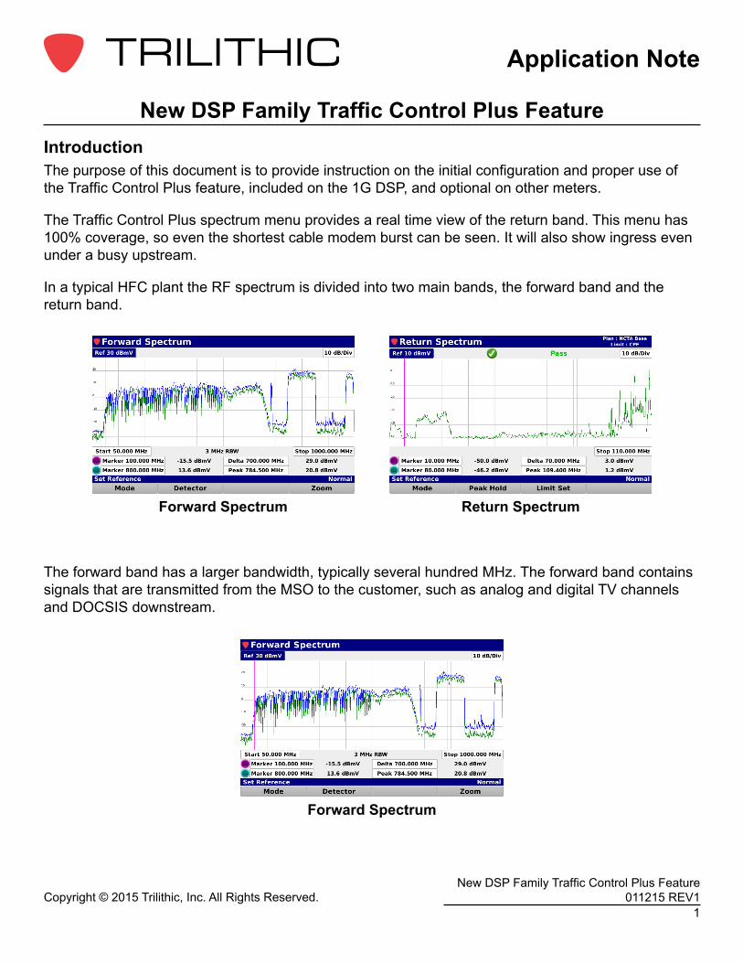
New DSP Family Traffic Control Plus FeatureIntroductionThe purpose of this document is to provide instruction on the initial configuration and proper use of the Traffic Control Plus feature, included on the 1G DSP, and optional on other meters.
The Traffic Control Plus spectrum menu provides a real time view of the return band. This menu has 100% coverage, so even the shortest cable modem burst can be seen. It will also show ingress even under a busy upstream.
In a typical HFC plant the RF spectrum is divided into two main bands, the forward band and the return band.
Return SpectrumForward Spectrum
Forward Spectrum
The forward band has a larger bandwidth, typically several hundred MHz. The forward band contains signals that are transmitted from the MSO to the customer, such as analog and digital TV channels and DOCSIS downstream.

Application Note
Copyright © 2015 Trilithic, Inc. All Rights Reserved.2
New DSP Family Traffic Control Plus Feature 011215 REV1
The return band is smaller than the forward and varies in size from about 40 to 100 MHz. The return band is for signals transmitted from the customer back to the MSO. This is mainly DOCSIS upstreams. While the signals in the forward band are constant and easy to detect, the signals in the return tend to be bursty. This can cause issues while attempting to measure signals in the return band.
The Return Spectrum menu on the DSP line of meters is a powerful tool to troubleshoot and fix many issues in a typical cable TV system. It can be used to detect ingress and noise sources that can be disruptive to the return band of the system. These issues may lead to cable modem problems, causing a poor experience for the user. While the return spectrum is very good at detecting continuous signals, it does not always catch bursty signals such as a cable modem upstream channels. An upstream burst can be as short as 6.25 microseconds.
If there is enough upstream traffic, return spectrum may catch a full channel, or it may only catch a single slice of the channel. All these factors make it very difficult to differentiate traffic signal, noise, and ingress under the traffic.
Return Spectrum
Application Note
New DSP Family Traffic Control Plus Feature 011215 REV1Copyright © 2015 Trilithic, Inc. All Rights Reserved.
3
180 DSP Troubleshoot Menu 360 DSP Troubleshoot Menu
720 DSP Troubleshoot Menu 1G DSP Troubleshoot Menu
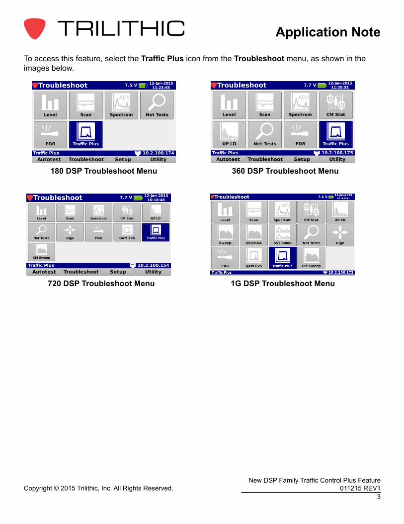
To access this feature, select the Traffic Plus icon from the Troubleshoot menu, as shown in the images below.
Application Note
Copyright © 2015 Trilithic, Inc. All Rights Reserved.4
New DSP Family Traffic Control Plus Feature 011215 REV1
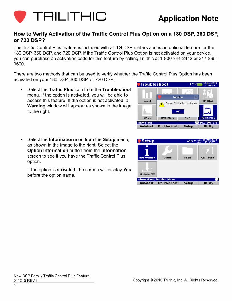
How to Verify Activation of the Traffic Control Plus Option on a 180 DSP, 360 DSP, or 720 DSP?The Traffic Control Plus feature is included with all 1G DSP meters and is an optional feature for the 180 DSP, 360 DSP, and 720 DSP. If the Traffic Control Plus Option is not activated on your device, you can purchase an activation code for this feature by calling Trilithic at 1-800-344-2412 or 317-895-3600.
There are two methods that can be used to verify whether the Traffic Control Plus Option has been activated on your 180 DSP, 360 DSP, or 720 DSP:
• Select the Traffic Plus icon from the Troubleshoot menu. If the option is activated, you will be able to access this feature. If the option is not activated, a Warning window will appear as shown in the image to the right.
• Select the Information icon from the Setup menu, as shown in the image to the right. Select the Option Information button from the Information screen to see if you have the Traffic Control Plus option.
If the option is activated, the screen will display Yes before the option name.
Application Note
New DSP Family Traffic Control Plus Feature 011215 REV1Copyright © 2015 Trilithic, Inc. All Rights Reserved.
5
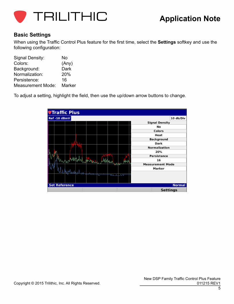
Basic SettingsWhen using the Traffic Control Plus feature for the first time, select the Settings softkey and use the following configuration:
Signal Density: No Colors: (Any) Background: Dark Normalization: 20% Persistence: 16 Measurement Mode: Marker
To adjust a setting, highlight the field, then use the up/down arrow buttons to change.
Application Note
Copyright © 2015 Trilithic, Inc. All Rights Reserved.6
New DSP Family Traffic Control Plus Feature 011215 REV1
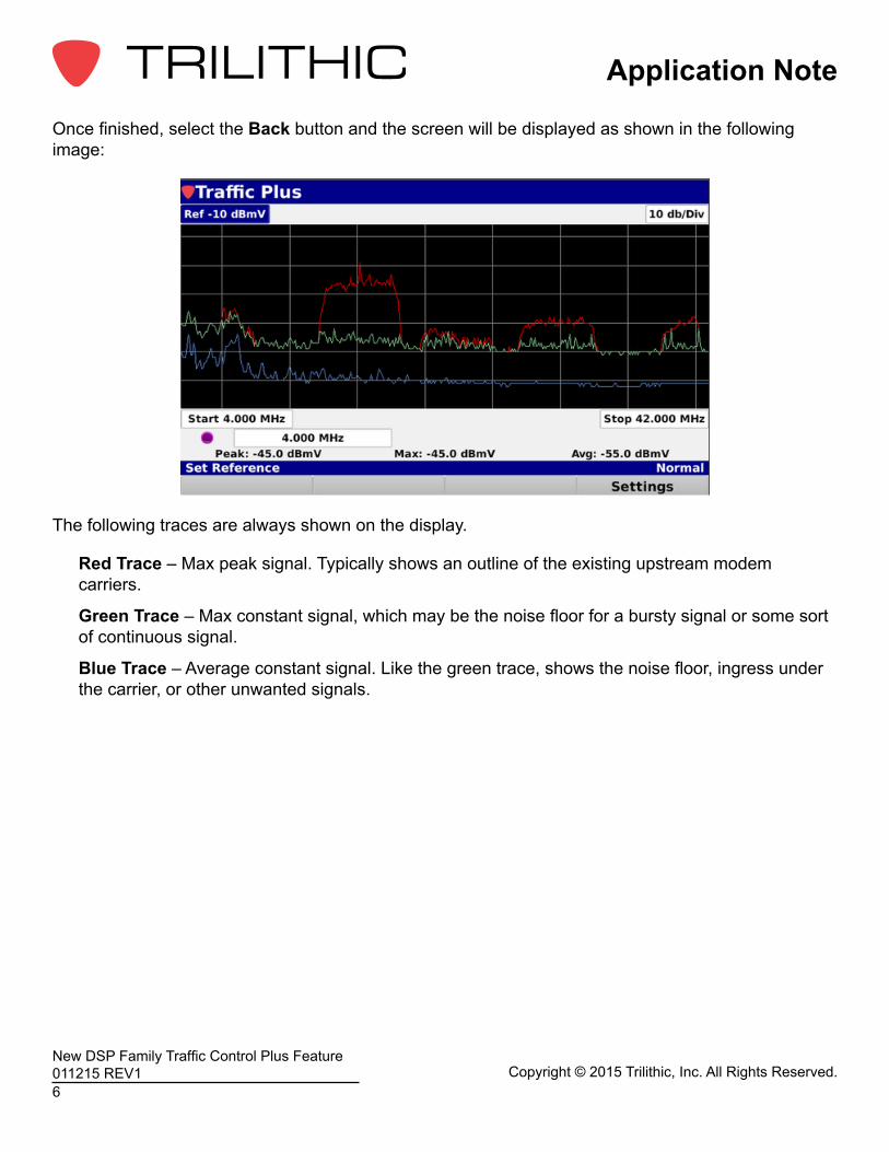
Once finished, select the Back button and the screen will be displayed as shown in the following image:
The following traces are always shown on the display.
Red Trace – Max peak signal. Typically shows an outline of the existing upstream modem carriers.
Green Trace – Max constant signal, which may be the noise floor for a bursty signal or some sort of continuous signal.
Blue Trace – Average constant signal. Like the green trace, shows the noise floor, ingress under the carrier, or other unwanted signals.
Application Note
New DSP Family Traffic Control Plus Feature 011215 REV1Copyright © 2015 Trilithic, Inc. All Rights Reserved.
7
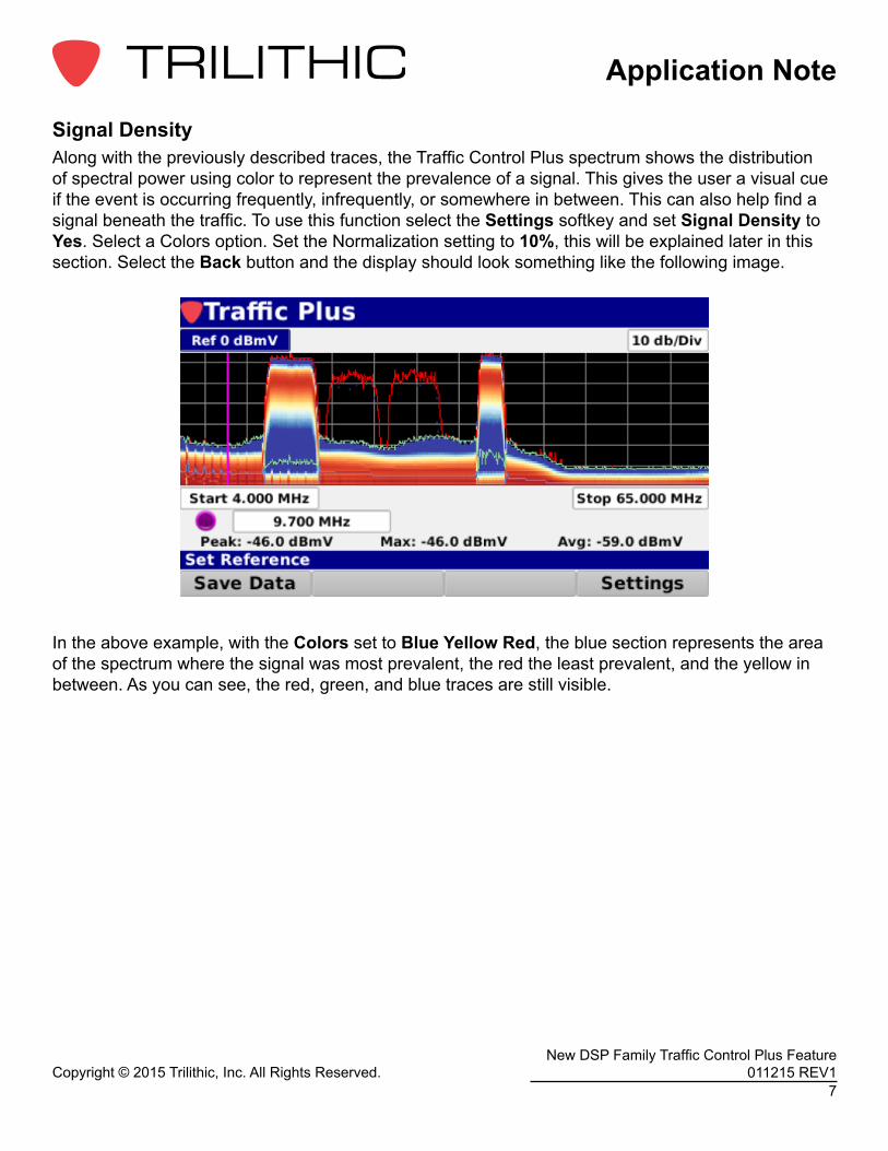
Signal DensityAlong with the previously described traces, the Traffic Control Plus spectrum shows the distribution of spectral power using color to represent the prevalence of a signal. This gives the user a visual cue if the event is occurring frequently, infrequently, or somewhere in between. This can also help find a signal beneath the traffic. To use this function select the Settings softkey and set Signal Density to Yes. Select a Colors option. Set the Normalization setting to 10%, this will be explained later in this section. Select the Back button and the display should look something like the following image.
In the above example, with the Colors set to Blue Yellow Red, the blue section represents the area of the spectrum where the signal was most prevalent, the red the least prevalent, and the yellow in between. As you can see, the red, green, and blue traces are still visible.
Application Note
Copyright © 2015 Trilithic, Inc. All Rights Reserved.8
New DSP Family Traffic Control Plus Feature 011215 REV1
The determination of what is most prevalent, least prevalent, and in between is dependent on the Normalization setting. This value is adjustable from 0.01% to 100%. In the example above where we have the Normalization set to 10%, the blue section, or most prevalent, shows signal power that was present at least 10% of the time. As you increase or decrease this value, you can see the effect on the display. Suggested settings for this value are 10 or 20%.
Other SettingsThe Background setting of the display can be either Dark or Light. Adjust this for the best readability of the display.
The Persistence setting can be a value from 1 to 32, selectable in multiples of two (1,2,4,8,16,32). This value has a direct effect on the number of samples used to build the specific traces. The end effect of this setting is the higher the value, the longer the max trace stays visible. A suggested value for this field is 8 or 16.
Application Note
New DSP Family Traffic Control Plus Feature 011215 REV1Copyright © 2015 Trilithic, Inc. All Rights Reserved.
9
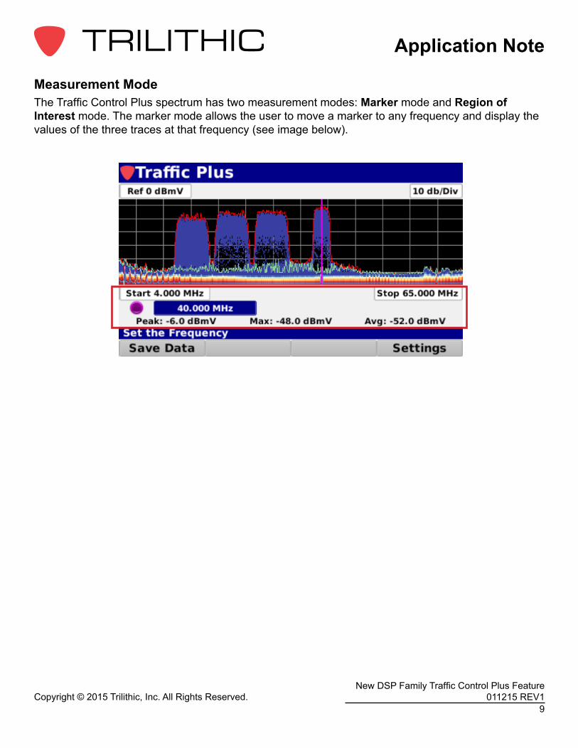
Measurement ModeThe Traffic Control Plus spectrum has two measurement modes: Marker mode and Region of Interest mode. The marker mode allows the user to move a marker to any frequency and display the values of the three traces at that frequency (see image below).
Application Note
Copyright © 2015 Trilithic, Inc. All Rights Reserved.10
New DSP Family Traffic Control Plus Feature 011215 REV1
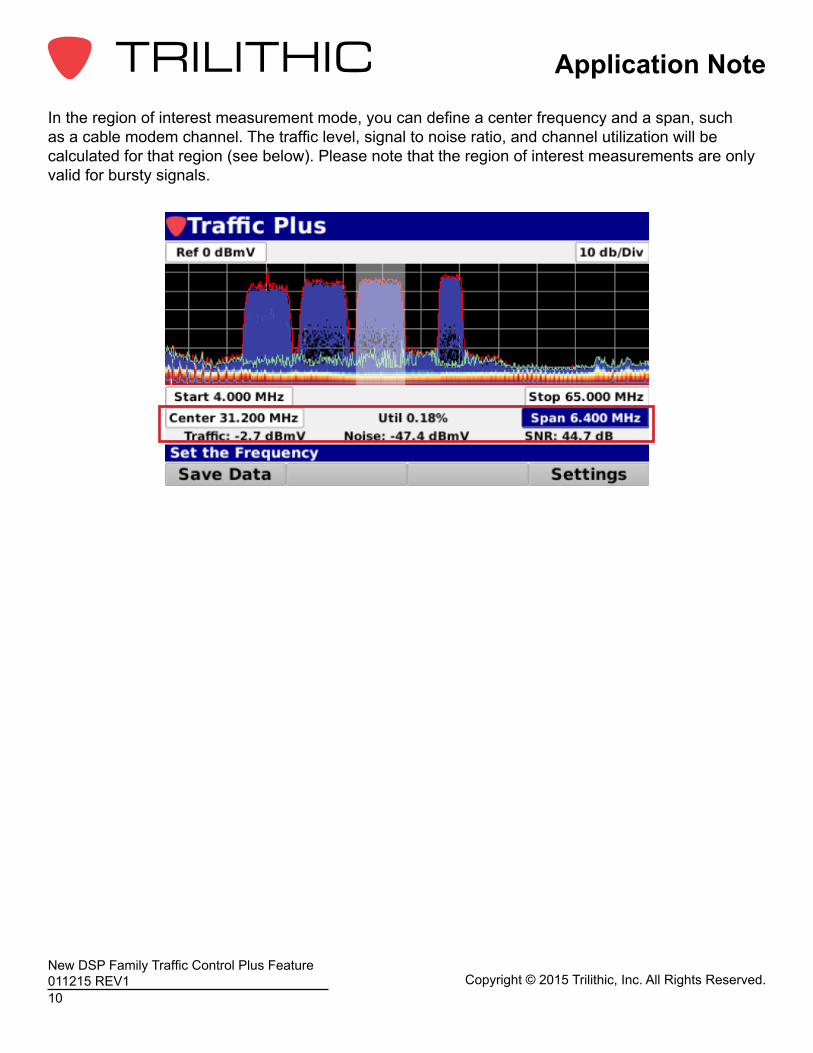
In the region of interest measurement mode, you can define a center frequency and a span, such as a cable modem channel. The traffic level, signal to noise ratio, and channel utilization will be calculated for that region (see below). Please note that the region of interest measurements are only valid for bursty signals.
Application Note
New DSP Family Traffic Control Plus Feature 011215 REV1Copyright © 2015 Trilithic, Inc. All Rights Reserved.
11
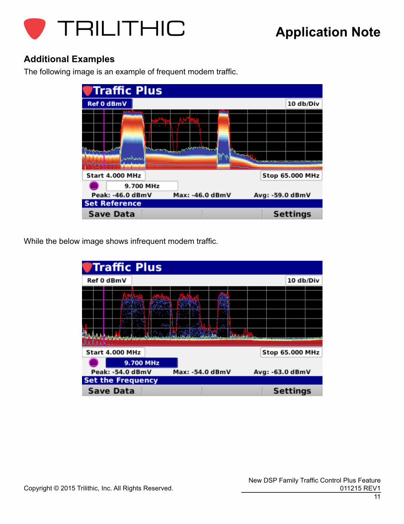
Additional ExamplesThe following image is an example of frequent modem traffic.
While the below image shows infrequent modem traffic.
Application Note
Copyright © 2015 Trilithic, Inc. All Rights Reserved.12
New DSP Family Traffic Control Plus Feature 011215 REV1
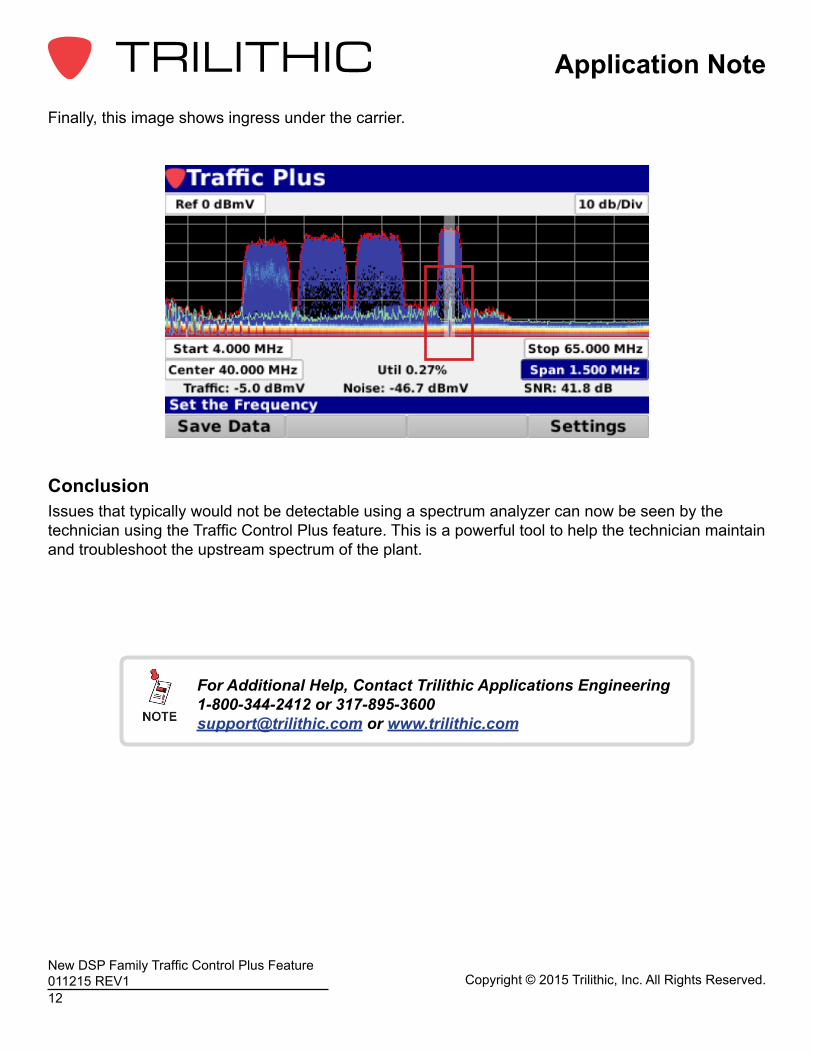
Finally, this image shows ingress under the carrier.
ConclusionIssues that typically would not be detectable using a spectrum analyzer can now be seen by the technician using the Traffic Control Plus feature. This is a powerful tool to help the technician maintain and troubleshoot the upstream spectrum of the plant.
For Additional Help, Contact Trilithic Applications Engineering 1-800-344-2412 or [email protected] or www.trilithic.com