Embed Size (px)
Citation preview

Logo-4c-originalgrosse
New Digital Aeronautical Communication Technologies to support future ATM concepts of SESAR
presented by Carl-Herbert Rokitanskyprepared by M. Ehammer, Th. Gräupl, B. Jandl
University of Salzburg / CoWi / ADC“Future Trends for Digital ATM Communication Technologies”, Salzburg, 21st of April 2009
Logo-4c-originalgrosse
Page 2University of Salzburg / CoWi / ADC – Ehammer, Gräupl, Jandl, Rokitansky <[email protected]>prepared by: M. Ehammer
Outline
Introduction – SESAR Developments and Goals
Cellular Terrestrial ATM Communication Technologies:B-AMC / L-DACS 1 – Some design backgroundand L-DACS 2 (covered in subsequent presentation)
Satellite-based ATM Communication Technology:ESA / IRIS ARTES 10 – a dual link approach
Integration of ATM services at network layer:NEWSKY Networking the Sky for future Applications

Logo-4c-originalgrosse
Page 3University of Salzburg / CoWi / ADC – Ehammer, Gräupl, Jandl, Rokitansky <[email protected]>prepared by: M. Ehammer
Single European Sky ATM Research (SESAR) Overview
SESAR networking technology roadmap:- Ground-ground network: Pan-European IP Network (PENS)- Air-ground network: No clear statement regarding roadmap for
networking technology (ATN/ISO vs. ATN/IPS):
- NEWSKY as input to SESAR WP9 (Aircraft System) and WP15 (Communication/Navigation/Surveillance System)
Source: SESAR D5
SESAR: Single European Sky ATM Research (2 Mrd. Euro)
(EU-Kommission, EuroControl, Industrie)
Development: 2008 – 2013+
Implementation: 2013 – 2020+
Logo-4c-originalgrosse
Page 4University of Salzburg / CoWi / ADC – Ehammer, Gräupl, Jandl, Rokitansky <[email protected]>prepared by: M. Ehammer
Single European Sky ATM Research (SESAR) Main Goals
Source: SESAR D5
• Increasement of Capacity by 73% (- 2020) up to 300% (long-term)
• Enhancement of Safety: triple by 2020; 10-times (long-term)
• Environment: Reduction of environmental impact by 10% per flight
• Costs: Reduction of ATM costs by 50% per flight

Logo-4c-originalgrosse
Page 5University of Salzburg / CoWi / ADC – Ehammer, Gräupl, Jandl, Rokitansky <[email protected]>prepared by: M. Ehammer
L-DACS Background
L-DACS stands for:L-Band Digital Aeronautical Communication System
Two remaining technology candidates remaining:- Based on broad-band (B-AMC and P34) approach: L-DACS1- Based on narrow-band (AMACS and LDL) approach: L-DACS2
L-DACS 1 evolved in several projects (and years)
NBMA system- Based on FDD (for Forward Link / Reverse Link) cells

Logo-4c-originalgrosse
Page 6University of Salzburg / CoWi / ADC – Ehammer, Gräupl, Jandl, Rokitansky <[email protected]>prepared by: M. Ehammer
L-DACS Design Goals of LDACS 1
Based on recommendations of AP17- Fit requirements of COCRv2 (latency requirements)- Deterministic Medium Access Approach- Spectrum Efficiency- Adaptive Coding and Modulation (variable bit rates)- Implementation complexity should be low- and many more …

Logo-4c-originalgrosse
Page 7University of Salzburg / CoWi / ADC – Ehammer, Gräupl, Jandl, Rokitansky <[email protected]>
B-AMC as L-DACS1 System
General L-DACS 1 capabilities- L-DACS 1 supports A/G and A/A communications
A/G communications centralized via ground stationA/A communications decentralized (not addressed here)
- L-DACS 1 supports data and voice communicationsFocus is on data communicationsVoice communications is a configurable option
- L-DACS 1 covers all ATS and safety-related AOC servicesExtendable to non safety-related AOC, AAC (and APC?) services
- L-DACS 1 is designed to meet the requirements for future radio systems as defined in COCR document

Logo-4c-originalgrosse
Page 8University of Salzburg / CoWi / ADC – Ehammer, Gräupl, Jandl, Rokitansky <[email protected]>
B-AMC / L-DACS 1 - PL – Inlay Approach
GSM
960
SSR
SSR11641150
DME DME DME
UA
T
978 1025 1035 1085 1095
JTIDS
969 1008
JTIDS
1053 1065
JTIDS (MIDS)
1113 1213
B-AMC A/G FL(crowded areas)B-AMC A/A
B-AMC A/G FL(no airborne DME)
B-AMC A/G RL
B-AMC A/G RL(optional)
Galileo/GPSDME (1157-1213)
B-AMC A/G RL(crowded areas)B-AMC A/A
f/MHz

Logo-4c-originalgrosse
Page 9University of Salzburg / CoWi / ADC – Ehammer, Gräupl, Jandl, Rokitansky <[email protected]>
Modeling of Interference from/to L-DACS 1 and existing DME
fD2
fB
fD1
rB
rD2
rD1
dD2
dD1
DME DoC
fD2 = fB ± 1,5 MHz
DME DoC
fD1 = fB ± 0,5 MHz
B-AMC DoC
A
B
C
D
hD2
hB
hD1
Non- overlapping B-AMC and DME DoCs
Overlapping B-AMC and DME DoCs
The B-AMC GS is operating (FL) on the channel fB , serving a circular Designed Operational Coverage (DoC) area with radius rB and height hB .Frequency planning requires knowledge about the constellation of adjacent DME GSs operating at fD1 = fB ± 0.5 MHz and fD2 = fB ± 1.5 MHz.The corresponding DME DoCs are assumed to be circular, with radii rD1 and rD2 and maximum designed heights hD1 and hD2 .The separation distances between the B-AMC DoC and the DME DoCs are described by dD1 and dD2 , for frequency separations of ± 0.5 MHz and ± 1.5 MHz, respectively.These distances are determined with a victim airborne RX placed at the boundary of the circular DoC of the victim system at the "appropriate" height.

Logo-4c-originalgrosse
Page 10University of Salzburg / CoWi / ADC – Ehammer, Gräupl, Jandl, Rokitansky <[email protected]>
Evaluation of Interference: L-DACS 1 GS towards Airborne DME Receiver
After applyingInterferenceKick-Out Criteriatowards DME:
Throughout Europe, for each L-DACS 1 cell (r=120nm or 60nm)an interference saftey margin towards DME can be realized(Yellow: 6 dB;Green: 12 dB)

Logo-4c-originalgrosse
Page 11University of Salzburg / CoWi / ADC – Ehammer, Gräupl, Jandl, Rokitansky <[email protected]>prepared by: M. Ehammer
L-DACS1 Frame-structure
RL DATA
FL DATA
D1
variable
Multi-Frame RL
C1
variable
FL DATA
Multi-Frame FL – Cell Specific ACM
RA RL RL RL RL
BC FL FL FL FL FL
Super-Frame
C1
C2
C3
C4
D1 D2 D3 D4
Multi-Frame #1 Multi-Frame #2 Multi-Frame #3 Multi-Frame #4
FL DATAC1
variable
FL DATA
Multi-Frame FL – User Specific ACM

Logo-4c-originalgrosse
Page 12University of Salzburg / CoWi / ADC – Ehammer, Gräupl, Jandl, Rokitansky <[email protected]>prepared by: M. Ehammer
Resource Acquisition Reservation Mechanism
Aircraft requests resources via DCCH.Ground station assigns resources via CCCH.Aircraft uses allocated resources to transmit data.Resources are requested for all LLC data within the MAC transmission queues.
DC
CC
Scope of Assignment on RL
CC
DC
Resource Request
AssignmentMulti-Frame

Logo-4c-originalgrosse
Page 13University of Salzburg / CoWi / ADC – Ehammer, Gräupl, Jandl, Rokitansky <[email protected]>prepared by: M. Ehammer
L-DACS1 Simulation Results – Medium Access
Linear increase of latency, while rising PIACPIAC versus Revers Link Latency
0
200
400
600
800
1000
1200
1400
1600
1800
2000
0 100 200 300 400 500 600
PIAC
Tim
e in
Mill
isec
onds
RL Latency - 95% Qtl.
RL Latency - mean
RL - Latency - mean (theory)
Linear (RL Latency - 95% Qtl.)
Linear (RL Latency - mean)
Latency requirement without A-EXEC (1400 ms):
up to 400 A/C in a single cell
Linear Regression of simulated RL latency (mean)
Theoretical prediction of RL latency (mean)
Latency requirement with A-EXEC (740 ms):
up to 200 A/C in a single cell

Logo-4c-originalgrosse
Page 14University of Salzburg / CoWi / ADC – Ehammer, Gräupl, Jandl, Rokitansky <[email protected]>14

Logo-4c-originalgrosse
Page 15University of Salzburg / CoWi / ADC – Ehammer, Gräupl, Jandl, Rokitansky <[email protected]>
Iris/ARTES 10 Program
Iris/ARTES 10 is a dedicated ESA program to support SESAR("Single European Sky ATM Research") under the umbrella of ESA’s Advanced Research in Telecommunication Systems program (ARTES)
It aims to develop a new Air-Ground communication system for Air Traffic Management as the satellite-based communication solution for the SESAR program.
Three phases:- Definition Phase until 2009.- Development Phase post 2009- Target satellite launch in 2013.
15

Logo-4c-originalgrosse
Page 16University of Salzburg / CoWi / ADC – Ehammer, Gräupl, Jandl, Rokitansky <[email protected]>
Iris/ARTES 10 Program
SESAR schedule vs. Iris phases
16

Logo-4c-originalgrosse
Page 17University of Salzburg / CoWi / ADC – Ehammer, Gräupl, Jandl, Rokitansky <[email protected]>
Analysis of Communication System Capacity
USBG contributed the ATM traffic model to the analysis of the required communication system capacity:
Used to refine the system requirements.Used for early performance assessment.
17

Logo-4c-originalgrosse
Page 18University of Salzburg / CoWi / ADC – Ehammer, Gräupl, Jandl, Rokitansky <[email protected]>
Analysis of Communication System Capacity
Analysis of the required communication system capacity:- Identify area of interest and reference air traffic data.For years 2013 until 2025:1. Estimate the air traffic growth in the area of interest.2. Estimate the future air traffic distribution and density.3. Estimate the required communication system capacity of
the Iris system.
- Provide input to the performance evaluation.System design is still ongoing.Not discussed here.
18

Logo-4c-originalgrosse
Page 19University of Salzburg / CoWi / ADC – Ehammer, Gräupl, Jandl, Rokitansky <[email protected]>
Area of Interest
The area of interest of the Iris/ARTES10 program is defined by the possible radio coverage of a GEO satellite positioned “over Europe and the Atlantic”.- It is assumed that this is contained in the
geographic area between 80° W to 80° E and 80°S to 80° N.
19

Logo-4c-originalgrosse
Page 20University of Salzburg / CoWi / ADC – Ehammer, Gräupl, Jandl, Rokitansky <[email protected]>
Area of Interest
20
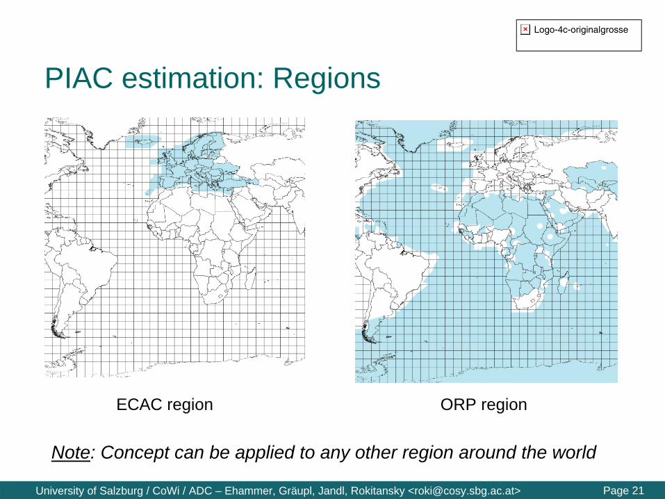
The area of interest is divided into three regions:- Controlled airspace of
ECAC countries (green).- Controlled airspace of
non-ECAC countries (white).
- Oceanic, remote, or polar (ORP) area (blue).
Based on 2007 US National Geospatial Intelligence Agency (NGA) data.
Logo-4c-originalgrosse
Page 21University of Salzburg / CoWi / ADC – Ehammer, Gräupl, Jandl, Rokitansky <[email protected]>
PIAC estimation: Regions
ECAC region ORP region
Note: Concept can be applied to any other region around the world
Logo-4c-originalgrosse
Page 22University of Salzburg / CoWi / ADC – Ehammer, Gräupl, Jandl, Rokitansky <[email protected]>
Reference Air TrafficAir traffic reference day: 31st Aug. 2007- Based on CFMU (Eurocontrol) and OAG (worldwide scheduled flights)
data.
- For airport relations (departure – destination) contained in CFMU and OAG: OAG contains 95.3% of CMFU flights.
- OAG data contains flights with airport relations not present in CMFU.Mostly flights outside of Europe.
- CFMU contains flights with airport relations not present in OAG.Mostly military flights, general aviation, and short term business flights.Additional flights were added to the OAG data to account for these extra flights.
- Reference day = CMFU data + extended OAG data
- Tool used to simulate Air Traffic in area of interest: NAVSIM
22
Logo-4c-originalgrosse
Page 23University of Salzburg / CoWi / ADC – Ehammer, Gräupl, Jandl, Rokitansky <[email protected]>
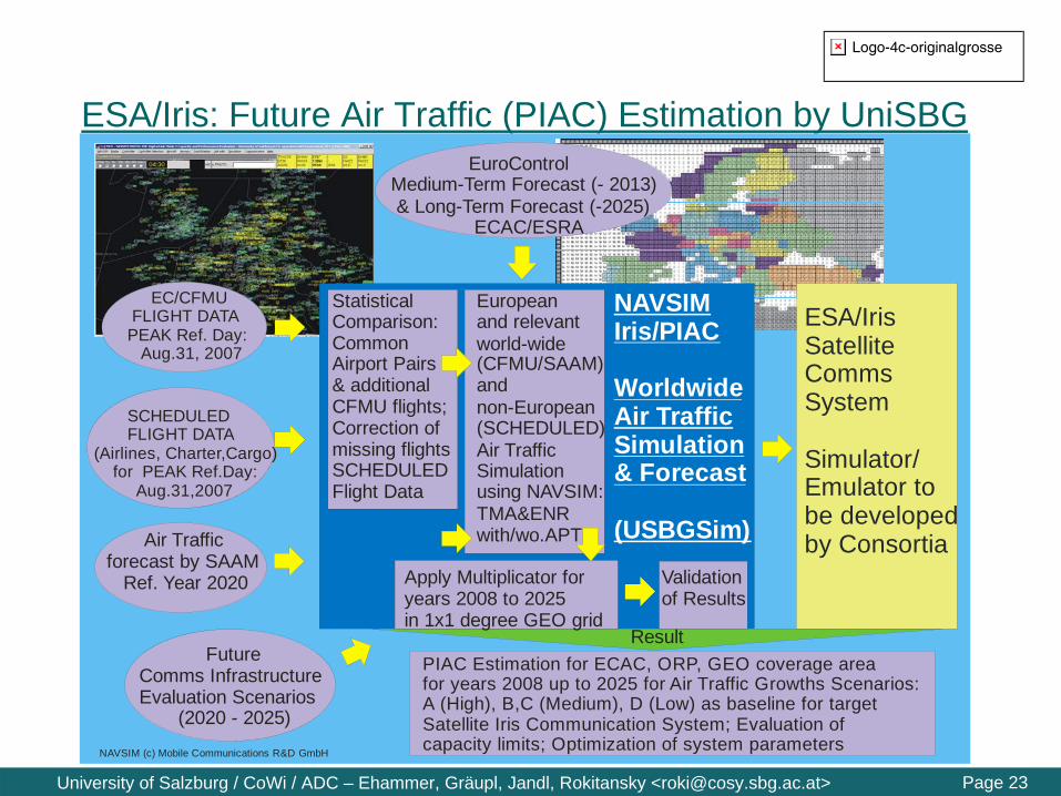
ESA/Iris: Future Air Traffic (PIAC) Estimation by UniSBG EuroControl Medium-Term Forecast (- 2013) & Long-Term Forecast (-2025) ECAC/ESRA
NAVSIMIris/PIAC
WorldwideAir TrafficSimulation& Forecast
(USBGSim)
EC/CFMU FLIGHT DATA PEAK Ref. Day: Aug.31, 2007
Air Traffic forecast by SAAM Ref. Year 2020
NAVSIM (c) Mobile Communications R&D GmbH
ESA/IrisSatelliteCommsSystem
Simulator/Emulator tobe developed by Consortia
Validationof Results
PIAC Estimation for ECAC, ORP, GEO coverage areafor years 2008 up to 2025 for Air Traffic Growths Scenarios: A (High), B,C (Medium), D (Low) as baseline for target Satellite Iris Communication System; Evaluation of capacity limits; Optimization of system parameters
Europeanand relevantworld-wide(CFMU/SAAM)and non-European(SCHEDULED)Air TrafficSimulationusing NAVSIM:TMA&ENRwith/wo.APT
SCHEDULED FLIGHT DATA (Airlines, Charter,Cargo) for PEAK Ref.Day: Aug.31,2007
StatisticalComparison:CommonAirport Pairs& additionalCFMU flights;Correction ofmissing flightsSCHEDULEDFlight Data
Apply Multiplicator foryears 2008 to 2025 in 1x1 degree GEO grid
FutureComms InfrastructureEvaluation Scenarios (2020 - 2025)
Result

Logo-4c-originalgrosse
Page 24University of Salzburg / CoWi / ADC – Ehammer, Gräupl, Jandl, Rokitansky <[email protected]>
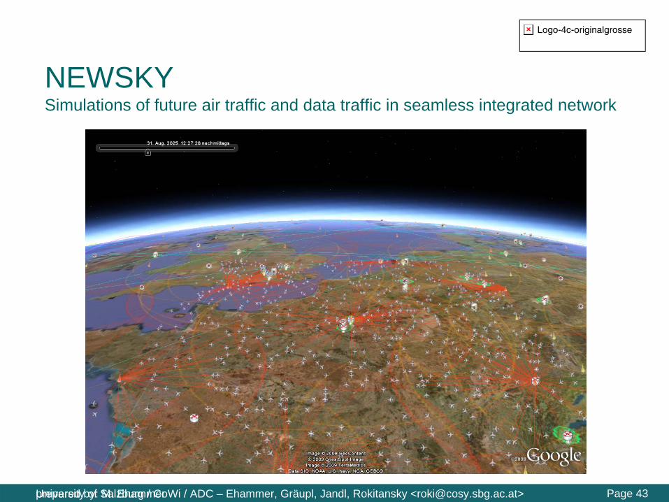
NAVSIM: Simulation of Real Air Traffic: August 31, 2007
Around115.000 flights/day world-wide (2007)estimated: 350.000 flights on peak days (2025)
EuroControl Data +Worldwide scheduledFlight Plans
EuroControlMedium- / LongtermForecasts: 2008 – 2025

Logo-4c-originalgrosse
Page 25University of Salzburg / CoWi / ADC – Ehammer, Gräupl, Jandl, Rokitansky <[email protected]>
Air Traffic GrowthThe air traffic growth estimation is based on Eurocontrol STATFOR studies for the ESRA countries:- Medium Term Forecast (2007-2013)
High, medium, low.- Long Term Forecast (2013-2025)
Scenario A (high-growth), B, C (medium-growth), D (low growth).
Medium term and long term growth forecasts are combined into four common scenarios:- High-A (no constraints; e.g. additional runways at airports if needed)- Med-B (strong growth assumed, but some capacity constraints apply)- Med-C (medium growth rates)- Low-D (changing attitudes: e.g. less long-haul tourist flights)
25

Logo-4c-originalgrosse
Page 26University of Salzburg / CoWi / ADC – Ehammer, Gräupl, Jandl, Rokitansky <[email protected]>
Air Traffic GrowthThe area of interest was partitioned into a 1°x1° grid.- Each grid cell was assigned to
one ECAC country or region (ORP, etc.).
- Each grid cell was linked to the estimated air traffic growth rate of its country/region.
- The growth rate is not constant. It depends on
Target timeCountry/regionForecast scenario
26
Estimated Air Traffic Growth Factor 2025/2007 High-A

Logo-4c-originalgrosse
Page 27University of Salzburg / CoWi / ADC – Ehammer, Gräupl, Jandl, Rokitansky <[email protected]>
Air Traffic Forecast: Results 2013
PIAC estimation High-growth - A Growth forecast High-growth - A

Logo-4c-originalgrosse
Page 28University of Salzburg / CoWi / ADC – Ehammer, Gräupl, Jandl, Rokitansky <[email protected]>
Air Traffic Forecast: Results 2020
PIAC estimation High-growth - A Growth forecast High-growth - A

Logo-4c-originalgrosse
Page 29University of Salzburg / CoWi / ADC – Ehammer, Gräupl, Jandl, Rokitansky <[email protected]>
Air Traffic Forecast: Results 2025
PIAC estimation High-growth - A Growth forecast High-growth - A
Logo-4c-originalgrosse
Page 30University of Salzburg / CoWi / ADC – Ehammer, Gräupl, Jandl, Rokitansky <[email protected]>
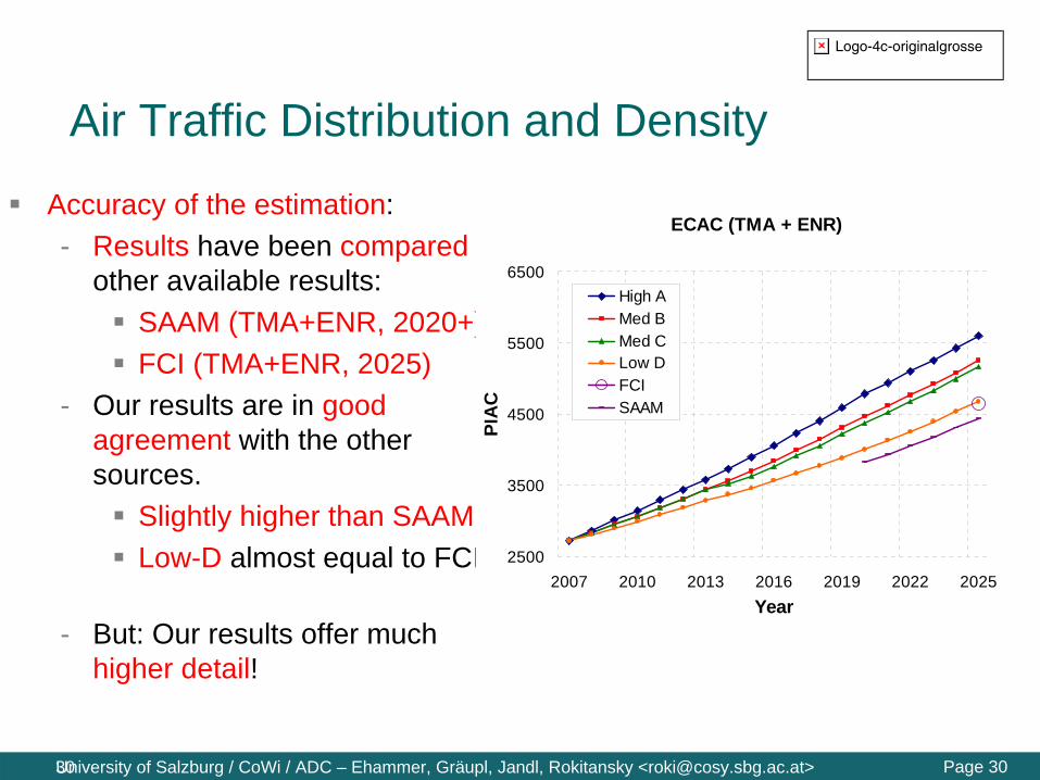
Air Traffic Distribution and Density
Accuracy of the estimation:- Results have been compared to
other available results:SAAM (TMA+ENR, 2020+).FCI (TMA+ENR, 2025)
- Our results are in good agreement with the other sources.
Slightly higher than SAAM.Low-D almost equal to FCI
- But: Our results offer much higher detail!
30
ECAC (TMA + ENR)
2500
3500
4500
5500
6500
2007 2010 2013 2016 2019 2022 2025Year
PIA
C
High AMed BMed CLow DFCISAAM

Logo-4c-originalgrosse
Page 31University of Salzburg / CoWi / ADC – Ehammer, Gräupl, Jandl, Rokitansky <[email protected]>
Data/Voice Traffic SimulationThe simulated air traffic was used to generate voice and data traffic according to the actual flight phase:- communications at departure gate, taxiing, take-off, - departure, en-route, arrival, approach, final approach, - landing, taxiing, communications at destination gate.
The voice model is based on Eurocontrol Reports (Aircraft DSB-AM Usage Profile).The data model is based on the COCRv2.- 24 ATS services- 21 AOC services- 2 NET services- Some services (12) were identified as unsuitable for
transmission over a satellite system and not included.
31

Logo-4c-originalgrosse
Page 32University of Salzburg / CoWi / ADC – Ehammer, Gräupl, Jandl, Rokitansky <[email protected]>
Data/Voice Traffic SimulationData message generation is triggered by events specified in COCRv2:- Change of domain, sector, ground position, etc.
Example (ATC Clearance (ACL) service):
32
APT: A/C on
ground , departure
APT : A/C on
ground , arrival
TMA TMA
ENR ENRORP
1 message exchange á :UL: 2x93 BDL: 2x93 B
2 message exchanges : 2 message
exchanges :
5 message exchanges :
5 message exchanges :
2 message exchanges :
1 message exchanges :

Logo-4c-originalgrosse
Page 33University of Salzburg / CoWi / ADC – Ehammer, Gräupl, Jandl, Rokitansky <[email protected]>
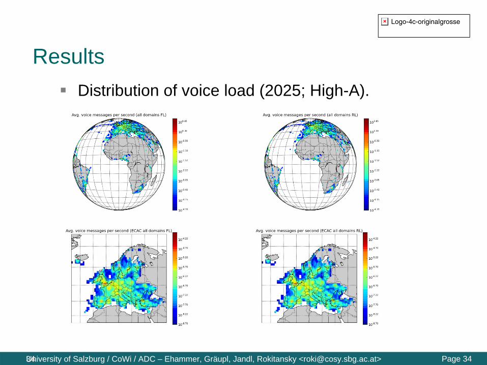
Results
Various scenarios were assessed and evaluated during the Iris/ARTES 10 study.- Three TL ACKs scenarios.- With/without/modified WXGRAPH.- Concentration of different areas of interest.
Results presented here:- Worst case TL ACKs.- Unmodified WXGRAPH service (most demanding case).- ECAC area only.
33
Logo-4c-originalgrosse
Page 34University of Salzburg / CoWi / ADC – Ehammer, Gräupl, Jandl, Rokitansky <[email protected]>
ResultsDistribution of voice load (2025; High-A).
34

Logo-4c-originalgrosse
Page 35University of Salzburg / CoWi / ADC – Ehammer, Gräupl, Jandl, Rokitansky <[email protected]>
ResultsDistribution of data load (2025; High-A).
35

Logo-4c-originalgrosse
Page 36University of Salzburg / CoWi / ADC – Ehammer, Gräupl, Jandl, Rokitansky <[email protected]>
ResultsEvolution of Iris data and voice traffic in the ECAC area (High-A).
36
2013 2020 p1 2020 p2 2025
min 16.0 22.2 15.8 40.3
avg 578.7 936.9 2250.8 4453.6
95% 679.9 1064.6 2786.2 5215.5
99% 729.8 1131.0 3068.0 5553.5
max 804.9 1323.8 3425.8 6160.3
stdev 61.6 77.4 313.0 453.4peak/avg. 1.4 1.4 1.5 1.4
2013 2020 p1 2020 p2 2025
min 30.0 31.7 34.0 4.7
avg 44.6 47.6 47.2 12.3
95% 51.7 55.3 54.0 16.0
99% 55.0 58.7 56.7 18.0
max 62.0 65.0 61.3 21.3
stdev 4.2 4.5 4.0 2.2
peak/avg. 1.4 1.4 1.3 1.7

Logo-4c-originalgrosse
Page 37University of Salzburg / CoWi / ADC – Ehammer, Gräupl, Jandl, Rokitansky <[email protected]>
ResultsData message size distribution:- Strong asymmetry between frequency and volume: Smallest
messages are most frequent, but (infrequent and) large messages contribute most to the traffic volume.
37

Logo-4c-originalgrosse
Page 38University of Salzburg / CoWi / ADC – Ehammer, Gräupl, Jandl, Rokitansky <[email protected]>
NEWSKY Goals: Networking the Sky
NEWSKY co-funded by the European Commission:Development of a concept and preliminary design of an integrated aeronautical communication network with focus on air-ground communications and IPv6 technologies
INTERNET in the Sky !
Air/Ground(terrestrial)
via Satellite
direct Air/Air Comms

Logo-4c-originalgrosse
Page 39University of Salzburg / CoWi / ADC – Ehammer, Gräupl, Jandl, Rokitansky <[email protected]>
NEWSKY: Integration of Different Data Links
newsk...
newsky ...
newsk...Kopie 3
nK4
news...Kopie
news...Kopie
newsky_... newsky_...
newsky ...
ground network
air-air links
satellite links (Inmarsat, Iridium NEXT, ESA Iris, DVB-S2, …)
airport links (Aero-WiMAX)
point-to-point air-ground links (VDL2, L-DACS-1/2)
Several data links are required to fulfil the ATM communication requirements (SESAR / Eurocontrol, NextGen / Federal Aviation Administration (USA))Further data links are foreseen for APC
Airport TMA/Enroute
ADS-B, Wake
Cellular,terrestrial
Oceanic, Remote, Polar
(ORP)

Logo-4c-originalgrosse
Page 40University of Salzburg / CoWi / ADC – Ehammer, Gräupl, Jandl, Rokitansky <[email protected]>
NEWSKY and SESAR
SESAR networking technology roadmap:- Ground-ground network: Pan-European IP Network (PENS)- Air-ground network: No clear statement regarding roadmap
for networking technology (ATN/ISO vs. ATN/IPS):
- NEWSKY as input to SESAR WP9 (Aircraft System) and WP15 (Communication/Navigation/Surveillance System)
Source: SESAR D5
Development: 2008 – 2013+
Implementation: 2013 – 2020+

Logo-4c-originalgrosse
Page 41University of Salzburg / CoWi / ADC – Ehammer, Gräupl, Jandl, Rokitansky <[email protected]>prepared by: M. Ehammer
NEWSKY Overall & Security Architecture
ATS CNATS CN
AOC CN
AOC LFNATS LFN
ATS LFN
SAGSAG
SAGSAG
SAG SAG
ATS Services AOC Services
ATS Services
MRMR
MR
ANSP w/o ACCESS NETWORK
ANSP with ACCESS NETWORK
Access Router
GACSPNETWORK
DiffServ DomainMobility TunnelSecurity TunnelDSCP Tagging
LFN: Local Fixed NodeSAG: Security Access GatewayMR: Mobile RouterCN: Correspondent Node
ANSP: Aeronautical Navigation Service ProviderGACSP: Global Aeronautical Communication Service ProviderAOC: Aeronautical Operational ServiceATS: Air Traffic Service
Logo-4c-originalgrosse
Page 42University of Salzburg / CoWi / ADC – Ehammer, Gräupl, Jandl, Rokitansky <[email protected]>prepared by: M. Ehammer
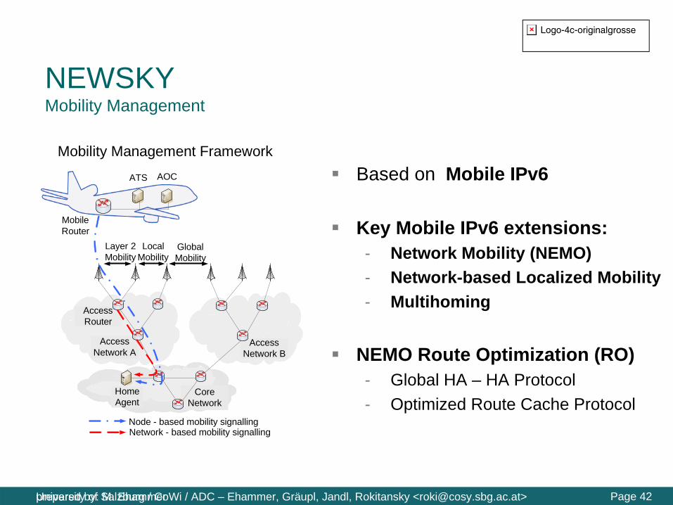
NEWSKY Mobility Management
Access Network A
Access Router
Core Network
Home Agent
Layer 2 Mobility
Local Mobility
Global Mobility
Access Network B
Node - based mobility signallingNetwork - based mobility signalling
Mobility Management Framework
Mobile Router
ATS AOC Based on Mobile IPv6
Key Mobile IPv6 extensions:- Network Mobility (NEMO)- Network-based Localized Mobility- Multihoming
NEMO Route Optimization (RO)- Global HA – HA Protocol- Optimized Route Cache Protocol
Logo-4c-originalgrosse
Page 43University of Salzburg / CoWi / ADC – Ehammer, Gräupl, Jandl, Rokitansky <[email protected]>prepared by: M. Ehammer
NEWSKY Simulations of future air traffic and data traffic in seamless integrated network
Logo-4c-originalgrosse
Page 44University of Salzburg / CoWi / ADC – Ehammer, Gräupl, Jandl, Rokitansky <[email protected]>
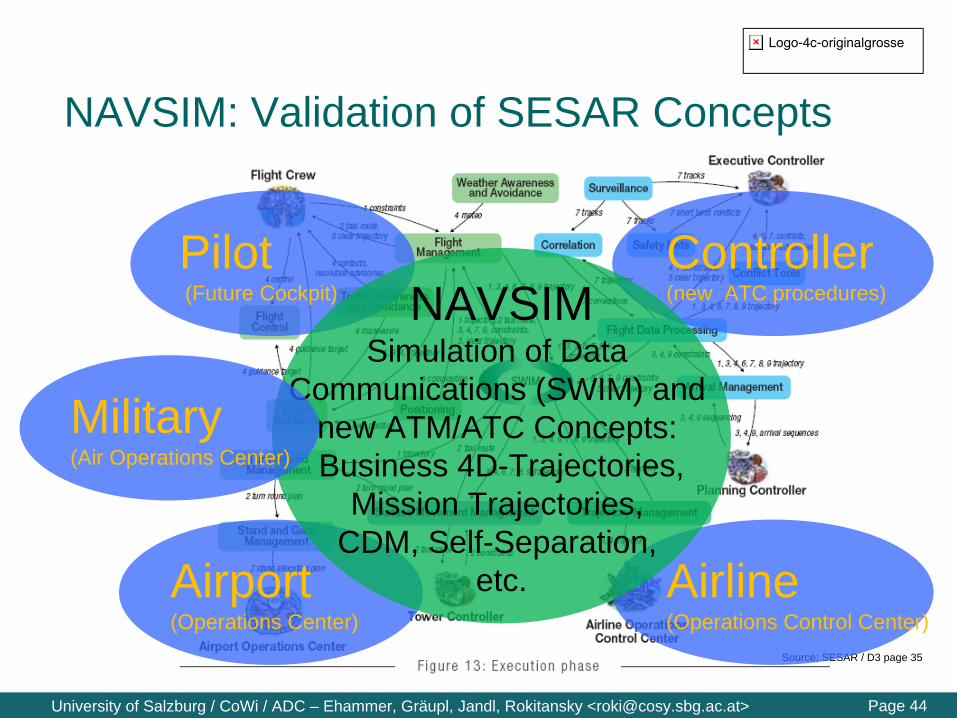
NAVSIM: Validation of SESAR Concepts
Source; SESAR / D3 page 35
Pilot (Future Cockpit)
Controller(new ATC procedures)
Airport(Operations Center)
Airline(Operations Control Center)
NAVSIMSimulation of Data
Communications (SWIM) andnew ATM/ATC Concepts: Business 4D-Trajectories,
Mission Trajectories, CDM, Self-Separation,
etc.
Military(Air Operations Center)

Logo-4c-originalgrosse
Page 45University of Salzburg / CoWi / ADC – Ehammer, Gräupl, Jandl, Rokitansky <[email protected]>
NAVSIM: European/worldwide Simulation of Air Traffic
based upon around 1 million navigation data
Detailed simulationof today's / future
worldwide air traffic
based on worldwide navigation data,
several thousands of aircraft are simulated
simultaneously

Logo-4c-originalgrosse
Page 46University of Salzburg / CoWi / ADC – Ehammer, Gräupl, Jandl, Rokitansky <[email protected]>
UniSBG: Simulation Service Architecture & Components
RadioCoverage
StatisticsService
Visualization
Airspace Scenario
Data-Link Service
Application Service
Logo-4c-originalgrosse
Page 47University of Salzburg / CoWi / ADC – Ehammer, Gräupl, Jandl, Rokitansky <[email protected]>prepared by: M. Ehammer
Conclusions (1 of 3)
Aero-WiMax communication technologies will provide high-speed data communications at airports
Terrestrial ATM communication technologies(L-DACS) are currently being specified and will provide digital data/voice communications in TMA/En-route areas with high performance fulfilling specified communication requirements (COCRv2)
Satellite-based ATM communication technologies will be operated - as dual link in parallel to terrestrial systems –supporting all relevant ATS/AOC/AAC applications

Logo-4c-originalgrosse
Page 48University of Salzburg / CoWi / ADC – Ehammer, Gräupl, Jandl, Rokitansky <[email protected]>prepared by: M. Ehammer
Conclusions (2 of 3)
Within NEWSKY (and follow-up projects, e.g. SANDRA) concepts are developed for a seamless integrated aeronautical communication network based on IPv6technologies
Detailed performance evaluations of future technologiesand SESAR ATM concepts are based on simulation of future air traffic scenarios (up to year 2025) and future data applications

Logo-4c-originalgrosse
Page 49University of Salzburg / CoWi / ADC – Ehammer, Gräupl, Jandl, Rokitansky <[email protected]>prepared by: M. Ehammer
Conclusions (3 of 3)
To support assessment of SESAR concepts/developments:- integrated comms technologies (AeroWiMax, L-DACS, SatCom)- extended system-wide information management (SWIM)- new ATM concepts (e.g. airborne/self-separation, etc.), based on:- Business 4D-trajectories / Mission trajectories, and- Collaborative Decision Making (CDM) between key players:
Controllers, Pilots, Airports,Airline/Military
will be evaluated in integrated simulation scenarios using powerful tools (e.g. SESAR JU WP3, NAVSIM/USBG, etc.).
Note: DEMO of NAVSIM/USBG Simulation Tools during Coffee Break

Logo-4c-originalgrosse
Page 50University of Salzburg / CoWi / ADC – Ehammer, Gräupl, Jandl, Rokitansky <[email protected]>prepared by: M. Ehammer
Thank you for your attentionContact:
Carl-Herbert Rokitansky
[email protected] Phone: +43-664-85 25 347


![Aeronautical Mobile Satellite Data Communication Experiments · evaluated and land mobile satellite communication experiments were performed by these devices[2 ]-4. This time, the](https://img.pdfslide.us/doc/110x75/5e28f29e5e8d3c24e02404e6/aeronautical-mobile-satellite-data-communication-evaluated-and-land-mobile-satellite.jpg)