Embed Size (px)
Citation preview
New Developments in Joint Sealing P ractice for Longer Spans STEWART C. WATSON, Acme Highway Products Corpor ation
ABRIDGMENT
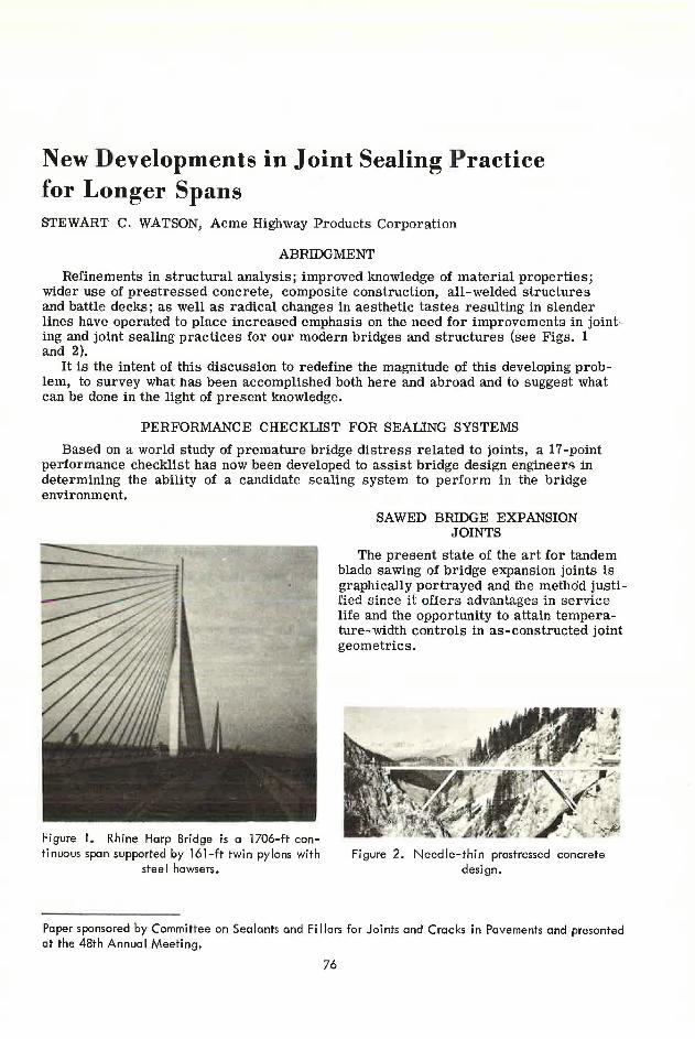
Refinements in structural analysis; improved knowledge of material properties; wider use of prestressed concrete, composite construction, all-welded structures and battle decks; as well as radical changes in aesthetic tastes resulting in slender lines have operated to place increased emphasis on the need for improvements in jointing and joint sealing practices for our modern bridges and structures (see Figs. 1 and 2).
It is the intent of this discussion to redefine the magnitude of this developing problem, to survey what has been accomplished both here and abroad and to suggest what can be done in the light of present knowledge.
PERFORMANCE CHECKLIST FOR SEALING SYSTEMS
Based on a world study of premature bridge distress related to joints, a 17-point performance checklist has now been developed to assist bridge design engineers in determining the ability of a candidate sealing system to perform in tlie bridge environment.
Hgure I. Rhine Harp Bridge is a 1706-ft continuous span supported by 161-ft twin pylons with
stee I hawsers.
SAWED BRIDGE EXPANSION JOINTS
The present state of the art for tandem blade sawing of bridge expansion joints is graphically portrayed and the method justified since it offers advantages in service life and the opportunity to attain temperature-width controls in as-constructed joint geometrics.
Figure 2. Needle-thin prestressed concrete design.
Paper sponsored by Committee on Sealants and Fi I lers for Joints and Cracks in Pavements and presented at the 48th Annua I Meeting .
76
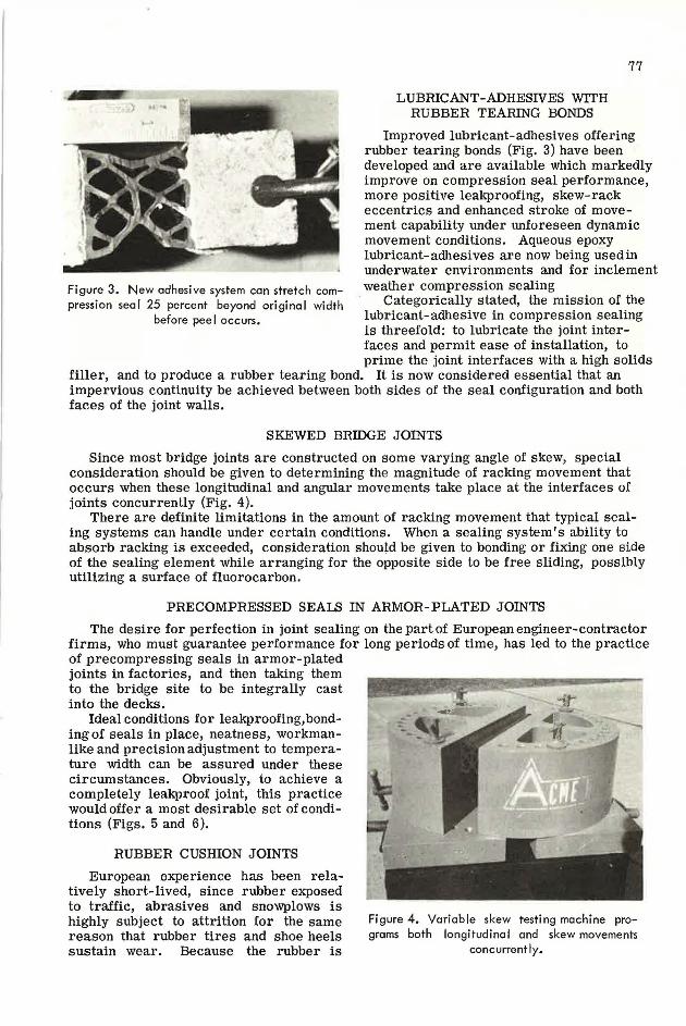
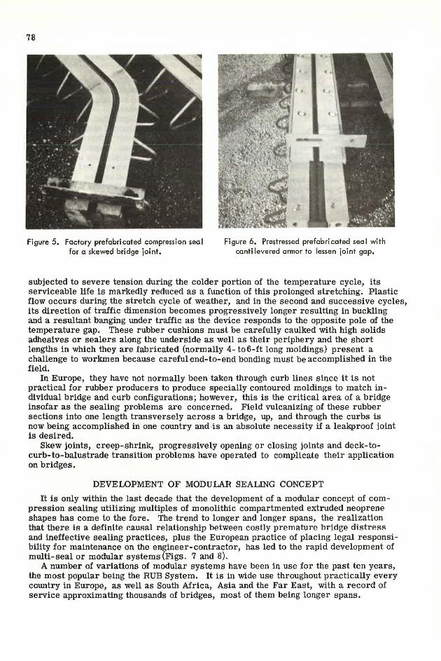
Figure 3. New adhesive system can stretch compression sea) 25 percent beyond original width
before peel occurs.
LUBRICANT-ADHESIVES WITH RUBBER TEARING BONDS
77
Improved lubricant-adhesives offering rubber tearing bonds (Fig. 3) have been developed and are available which markedly improve on compression seal performance, more positive leakproofing, skew-rack eccentrics and enhanced stroke of movement capability under unforeseen dynamic movement conditions. Aqueous epoxy lubricant-adhesives are now being usedin underwater environments and for inclement weather compression sealing
Categorically stated, the mission of the lubricant-adhesive in compression sealing is threefold: to lubricate the joint interfaces and permit ease of installation, to prime the joint interfaces with a high solids
filler, and to produce a rubber tearing bond. It is now considered essential that an impervious continuity be achieved between both sides of the seal configuration and both faces of the joint walls.
SKEWED BRIDGE JOINTS
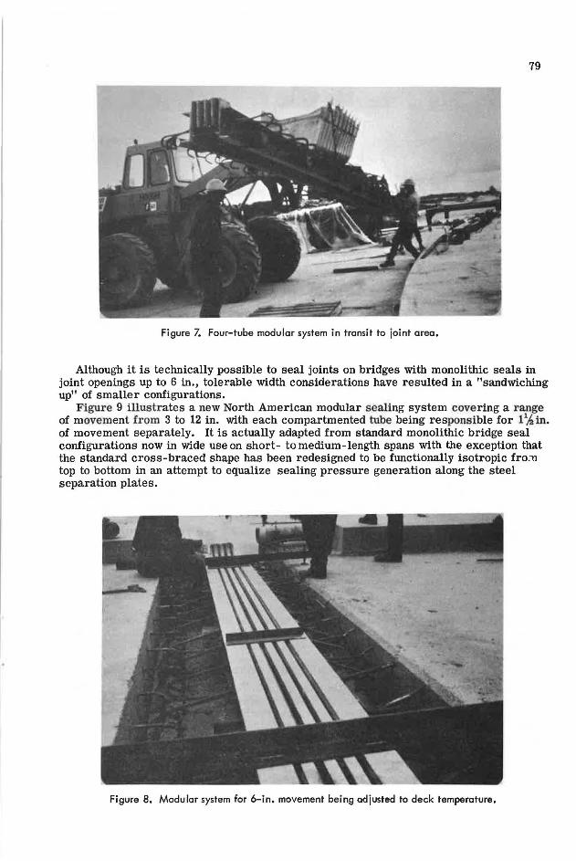
Since most bridge joints are constructed on some varying angle of skew, special consideration should be given to determining the magnitude of racking movement that occurs when these longitudinal and angular movements take place at the interfaces of joints concurrently (Fig. 4).
There are definite limitations in the amount of racking movement that typical sealing systems can handle under certain conditions. When a sealing system's ability to absorb racking is exceeded, consideration should be given to bonding or fixing one side of the sealing element while arranging for the opposite side to be free sliding, possibly utilizing a surface of fluorocarbon.
PRECOMPRESSED SEALS IN ARMOR-PLATED JOINTS
The desire for perfection in joint sealing on the part of European engineer-contractor firms, who must guarantee performance for long periods of time, has led to the practice of precompressing seals in armor-plated joints in factories, and then taking them to the bridge site to be integrally cast into the decks.
Ideal conditions for leakproofing,bonding of seals in place, neatness, workmanlike and precision adjustment to temperature width can be assured under these circumstances. Obviously, to achieve a completely leakproof joint, this practice would offer a most desirable set of conditions (Figs. 5 and 6 ).
RUBBER CUSHION JOINTS
European experience has been relatively short-lived, since rubber exposed to traffic, abrasives and snowplows is highly subject to attrition for the same reason that rubber tires and shoe heels sustain wear. Because the rubber is
Figure 4. Variable skew testing machine programs both longitudino I and skew movements
concurrently.
78
Figure 5. Factory prefabricated compression seal for a skewed bridge joint.
Figure 6. Prestressed prefabricated sea I with cantilevered armor to lessen joint gap.
subjected to severe tension during the colder portion of the temperature cycle, its serviceable life is markedly reduced as a function of this prolonged stretching. Plastic flow occurs during the stretch cycle of weather, and in the second and successive cycles, its direction of traffic dimension becomes progressively longer resulting in buckling and a resultant banging under traffic as the device responds to the opposite pole of the temperature gap. These rubber cushions must be carefully caulked with high solids adhesives or sealers along the underside as well as their periphery and the short lengths in which they are fabricated (normally 4- to6-ft long moldings) present a challenge to workmen because careful end-to-end bonding must be accomplished in the field.
In Europe, they have not normally been taken through curb lines since it is not practical for rubber producers to produce specially contoured moldings to match individual bridge and curb configurations; however, this is the critical area of a bridge insofar as the sealing problems are concerned. Field vulcanizing of these rubber sections into one length transversely across a bridge, up, and through the curbs is now being accomplished in one country and is an absolute necessity if a leakproof joint is desired.
Skew joints, creep-shrink, progressively opening or closing joints and deck-tocurb-to-balustrade transition problems have operated to complicate their application on bridges.
DEVELOPMENT OF MODULAR SEALING CONCEPT
It is only within the last decade that the development of a modular concept of com -pression sealing utilizing multiples of monolithic compartmented extruded neoprene shapes has come to the fore. The trend to longer and longer spans, the realization that there is a definite causal rela.tionship het.ween costly premature hridge distreRR and ineffective sealing practices, plus the European practice of placing legal responsibility for maintenance on the engineer-contractor, has led to the rapid development of multi-seal or modular systems (Figs. 7 and 8).
A number of variations of modular systems have been in use for the past ten years, the most popular being the RUB System. It is in wide use throughout practically every country in Europe, as well as South Africa, Asia and the Far East, with a record of service approximating thousands of bridges, most of them being longer spans.
79
Figure 7. Four-tube modular system in transit to joint area.
Although it is technically possible to seal joints on bridges with monolithic seals in joint openings up to 6 in., tolerable width considerations have resulted in a "sandwiching up" of smaller configurations.
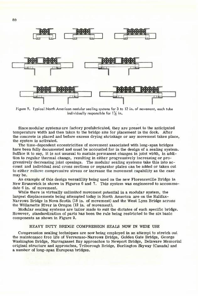
Figure 9 illustrates a new North American modular sealing system covering a r ange of movement from 3 to 12 in. with each compartmented tube being responsible for l 1h in. of movement separately. It is actually adapted from standard monolithic bridge seal configurations now in wide use on short- to medium-length spans with the exception that the standard cross-braced shape has been redesigned to be functionally isotropic fro.'11 top to bottom in an attempt to equalize sealing pressure generation along the steel separation plates.
Figure 8. Modular system for 6-in. movement being adjusted to deck temperature.
1
Figure 9. Typical North American modular sealing systems for 3 to 12 in. of movement, each tube individually responsible for l ~ in .
Since modular systems are factory prefabricated, they are preset to the anticipated temperature width and then taken to the bridge site for placement in the deck. After the concrete is placed and before excess drying shrinkage or any movement takes place, the system is activated.
The time-dependent eccentricities of movement associated with long- span bridges have been fully documented and must be accounted for in the design of a sealing system. Suffice it to say, it is not unusual to sustain permanent changes in joint width, in addition to regular thermal change, resulting in either progressively increasing or progressively decreasing joint openings. The modular sealing systems take this into account and individual seal cross sections or separator plates can be added or taken out to either r elieve compressive stress or increase the movement capability as the case may be.
An example of this design versatility being used on the new Florenceville Bridge in New Brunswick is shown in Figures 6 and 7. This system was engineered to accommodate 6 in. of movement.
While there is virtually unlimited movement potential in a modular system, the largest displacements being attempted today in North America are on the HalifaxNarrows Bridge in Nova Scotia (18 in. of movement) and the West Lynn Bridge across the Willamette River in Oregon (12 in. of movement).
Modular sealing systems are tailor made to suit the dictates of each specific bridge. However, standardization of parts has been the rule being restricted to the six basic components as shown in Figure 9.
HEAVY DUTY BRIDGE COMPRESSION SEALS NOW IN WIDE USE
Compression sealing techniques are now being employed in an attempt to stretch out the maintenance free life of Verrazano-Narrows Dridge, Golden Gate Bridge, George Washington Bridge, Narraganset Bay approaches to Newport Bridge, Delaware Memorial original structure and approaches, Triborough Bridge, Burlington Skyway (Canada) and a number of long-span European bridges.