Embed Size (px)
Citation preview

MAGLEV 2002 17th International conference on magnetically levited systems and linear drives New development of mild steel with improved magnetic properties at low field Dr Peggy Schouller-Guinet, Research Engineer, Development and technical Advice Center Cockerill-Sambre, Arcelor Innovation. Philippe Harlet, Head of Development and Technical Advice Center Cockerill-Sambre, Arcelor Innovation. P. Cantinieaux, Nathalie Petit: Cockerill Sambre/ Wallonie Arcelor Abstract From all the magnetic materials, iron or extra mild steel still stay the one of the most popular cause of his excellent compromise between magnetic and mechanical properties associated with low cost prices. Cockerill Sambre Arcelor has been for a long time a specialist of magnetic steel presenting very high magnetic permeability at low field coupled with very low coercitivity and high saturation induction. These steels previously developed by cold rolling and annealing up to 1,5 mm thickness, are now available from a new thermomechanical hot rolling process up to 10 mm. This paper gives a summary of the manufacturing process and improvements implemented as well as an overview of the difficulties encountered during this production. Preliminary statistics obtained for the mechanical and magnetic steel properties are presented. The low-carbon steel sheet is used to manufacture yoke laminations which provide the return path for the magnetic flux and concurring to the mechanical rigidity of the LHC dipole and quadrupole structure in the new CERN accelerator in Geneva. More over, some new applications begin to be developed for shielding effect of this steel in term of protection from the magnetic field in some industrial activities. Key words: Silicon free magnetic steel; Core loss Shielding; Accelerator magnets; Permeability at low field; Hot rolled steel sheet Introduction Electrical and magnetic steels, in the form of laminated strips are used in electrical and magnetic equipment meant for generation, distribution and utilisation of electrical energy. Laminated steel sheets are assembled (EG by welding or by mechanical fastening) to form core of motor, generators, transformers, magnets… These soft magnetic cores are used to carry magnetic flux. Generally, electrical steels are classified as cold rolled grain oriented and cold rolled non-oriented depending of the texture of the material. When a ferro magnetic crystal is magnetised along different crystallographic directions, it gives rise to different magnetisation curves. In BCC iron / iron silicon crystal, the cube edges – the <100> family of directions – are the directions of easy magnetisation while the body diagonals corresponding to the family of <111> directions are more difficult to magnetise. The <110> family of direction presents an intermediate behaviour. As presented at the figure 1, a lower energy is required to saturate the iron crystal in a easy direction like [110] than that needed to saturate the crystal in a difficult direction like [111].
The difference of energy due to the anisotropy is believed to result from spin orbit interaction of electron. Now, electrical and magnetic steels are universally produced through the cold rolling process route to achieve higher productivity, consistent hardness, better surface quality and uniform thickness. Classically, electrical or magnetic steels are elaborated by continuous casting with or without decarburation by vacuum treatment, hot rolled as semi product, cold rolled and annealed in steel making plant or by the customer. One of these product, Magnetil BC ®, was developed and used in the past for accelerator but this product was produced by a classical route for cold rolled and annealed steel, the maximum thickness available was 1,5 mm due to the limitation of opencoil batch annealing. To follow the requirements of one of his most prestigious customer: the CERN in Geneva, Cockerill Sambre Arcelor has developed and patented (12) a new thermomechanical route leading to the industrial production of hot rolled material without silicon (2). This original way of production offer a new potential of magnetic steel available from 1,5 mm up to 10 mm presenting a high permeability at low field, a low coercivity field and a good level of induction at high field. Scientific back ground / experimental details and metallurgical approach of these developments Since more then 10 years, Cockerill Sambre with the help of CRM has developed a new industrial hot rolling practice: rolling in the ferrite region (3,4,5,6,7,8). The concept of ferritic hot rolling of low carbon and ultra low carbon (figure 2) was initially introduced in view to produce from a conventional continuously cast slab, a cheap, soft and non-ageing hot band for direct use or subsequent cold rolling.

Fig.2 Cost reduction may be achieved in different ways among which the most evident one is energy saving by use of reduced temperature at the reheating furnace. A second one is related to a significant reduction of work roll wear due to a reduced entry temperature in the finishing mill. This low rolling temperature practice results also in additional benefits in term of hot rolled product quality which are less surface defects, improved flatness of the hot rolled strips due to reduced internal stresses owing to the fact that steel strips are transformed prior to cooling on the run out table. It is also important to mention that the oxide scale formed in this new practice is different in morphology and thickness as regards with the classical one: thinner gage, good adhesion give to this product new fonctionnalities (corrosion resistance and direct paintability). Effect of hardening and softening behaviours in the hot strained ferrite As demonstrated by Messien and Al.(3), using at the first step, dislocation density and strain in relation with the Bergström approach, a competition exists between: -Hardening effect (h parameter)– dynamical strain ageing, associated with a rapid increase of the rate of immobilisation of the dislocations as a consequence of pinning effect by solute atoms that appears to be proportional to the solute carbon content at the straining temperature what is logical in steel containing solute carbon. -Softening effect (r parameter) with an increase of recovery is observe in ELC steel strained above a critical temperature depending of the chemical composition. The softening behaviour is thus complex in steel containing solute carbon being described by two terms with different activation energy.
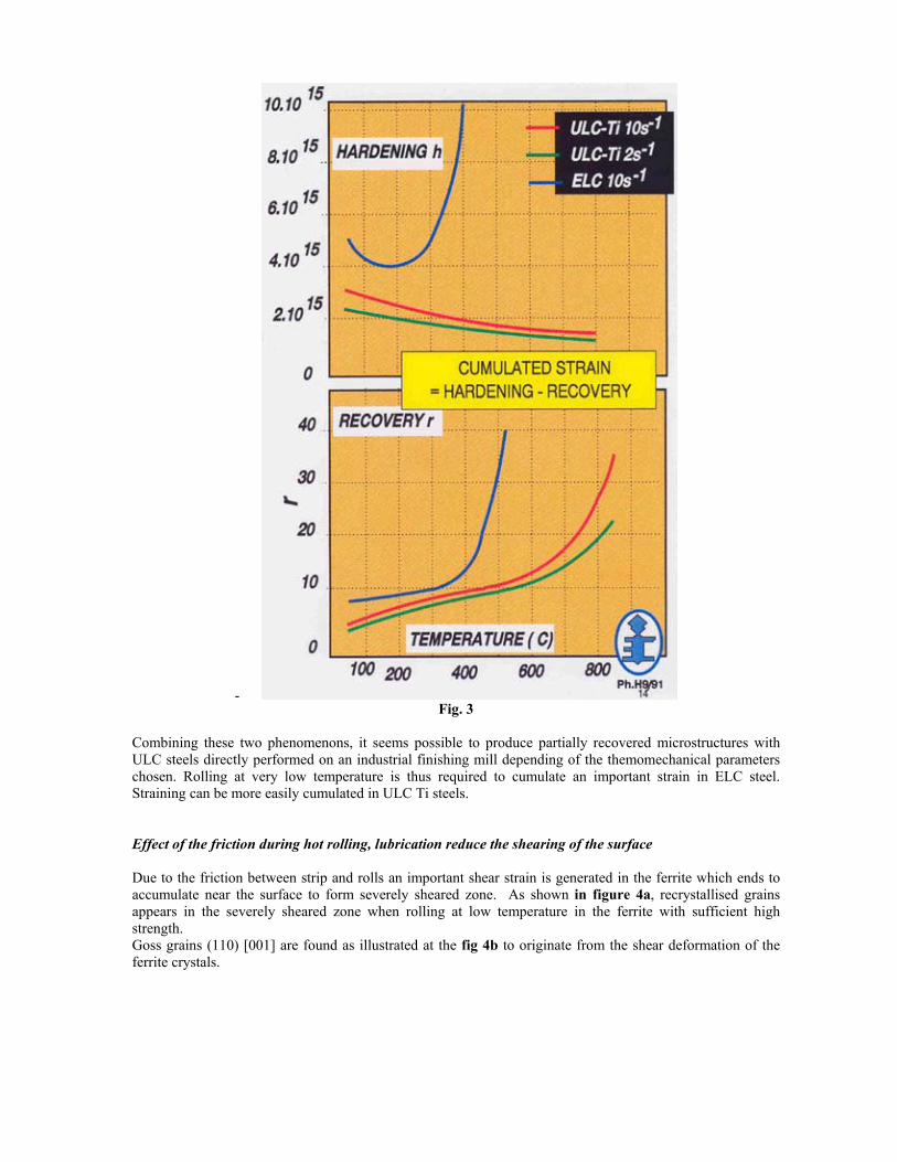
- Fig. 3
Combining these two phenomenons, it seems possible to produce partially recovered microstructures with ULC steels directly performed on an industrial finishing mill depending of the themomechanical parameters chosen. Rolling at very low temperature is thus required to cumulate an important strain in ELC steel. Straining can be more easily cumulated in ULC Ti steels. Effect of the friction during hot rolling, lubrication reduce the shearing of the surface Due to the friction between strip and rolls an important shear strain is generated in the ferrite which ends to accumulate near the surface to form severely sheared zone. As shown in figure 4a, recrystallised grains appears in the severely sheared zone when rolling at low temperature in the ferrite with sufficient high strength. Goss grains (110) [001] are found as illustrated at the fig 4b to originate from the shear deformation of the ferrite crystals.
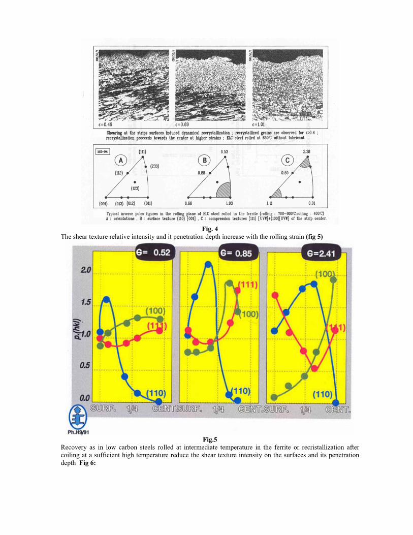
Fig. 4
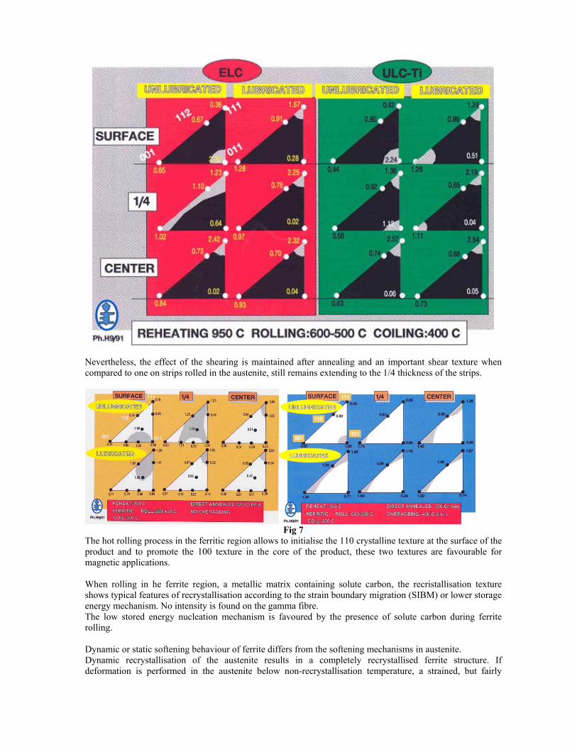
The shear texture relative intensity and it penetration depth increase with the rolling strain (fig 5)
Fig.5
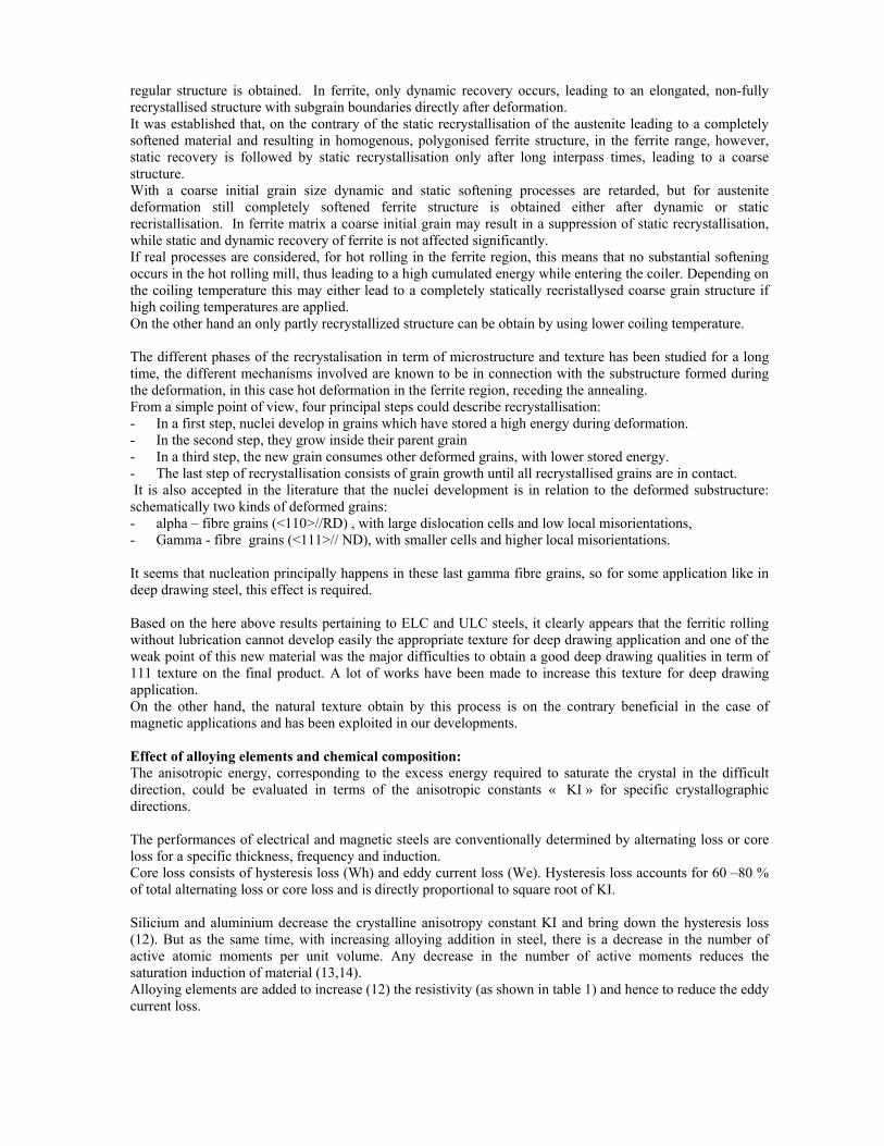
Recovery as in low carbon steels rolled at intermediate temperature in the ferrite or recristallization after coiling at a sufficient high temperature reduce the shear texture intensity on the surfaces and its penetration depth Fig 6:
Nevertheless, the effect of the shearing is maintained after annealing and an important shear texture when compared to one on strips rolled in the austenite, still remains extending to the 1/4 thickness of the strips.
Fig 7
The hot rolling process in the ferritic region allows to initialise the 110 crystalline texture at the surface of the product and to promote the 100 texture in the core of the product, these two textures are favourable for magnetic applications. When rolling in he ferrite region, a metallic matrix containing solute carbon, the recristallisation texture shows typical features of recrystallisation according to the strain boundary migration (SIBM) or lower storage energy mechanism. No intensity is found on the gamma fibre. The low stored energy nucleation mechanism is favoured by the presence of solute carbon during ferrite rolling. Dynamic or static softening behaviour of ferrite differs from the softening mechanisms in austenite. Dynamic recrystallisation of the austenite results in a completely recrystallised ferrite structure. If deformation is performed in the austenite below non-recrystallisation temperature, a strained, but fairly
regular structure is obtained. In ferrite, only dynamic recovery occurs, leading to an elongated, non-fully recrystallised structure with subgrain boundaries directly after deformation. It was established that, on the contrary of the static recrystallisation of the austenite leading to a completely softened material and resulting in homogenous, polygonised ferrite structure, in the ferrite range, however, static recovery is followed by static recrystallisation only after long interpass times, leading to a coarse structure. With a coarse initial grain size dynamic and static softening processes are retarded, but for austenite deformation still completely softened ferrite structure is obtained either after dynamic or static recristallisation. In ferrite matrix a coarse initial grain may result in a suppression of static recrystallisation, while static and dynamic recovery of ferrite is not affected significantly. If real processes are considered, for hot rolling in the ferrite region, this means that no substantial softening occurs in the hot rolling mill, thus leading to a high cumulated energy while entering the coiler. Depending on the coiling temperature this may either lead to a completely statically recristallysed coarse grain structure if high coiling temperatures are applied. On the other hand an only partly recrystallized structure can be obtain by using lower coiling temperature. The different phases of the recrystalisation in term of microstructure and texture has been studied for a long time, the different mechanisms involved are known to be in connection with the substructure formed during the deformation, in this case hot deformation in the ferrite region, receding the annealing. From a simple point of view, four principal steps could describe recrystallisation: - In a first step, nuclei develop in grains which have stored a high energy during deformation. - In the second step, they grow inside their parent grain - In a third step, the new grain consumes other deformed grains, with lower stored energy. - The last step of recrystallisation consists of grain growth until all recrystallised grains are in contact. It is also accepted in the literature that the nuclei development is in relation to the deformed substructure: schematically two kinds of deformed grains: - alpha – fibre grains (<110>//RD) , with large dislocation cells and low local misorientations, - Gamma - fibre grains (<111>// ND), with smaller cells and higher local misorientations. It seems that nucleation principally happens in these last gamma fibre grains, so for some application like in deep drawing steel, this effect is required. Based on the here above results pertaining to ELC and ULC steels, it clearly appears that the ferritic rolling without lubrication cannot develop easily the appropriate texture for deep drawing application and one of the weak point of this new material was the major difficulties to obtain a good deep drawing qualities in term of 111 texture on the final product. A lot of works have been made to increase this texture for deep drawing application. On the other hand, the natural texture obtain by this process is on the contrary beneficial in the case of magnetic applications and has been exploited in our developments. Effect of alloying elements and chemical composition: The anisotropic energy, corresponding to the excess energy required to saturate the crystal in the difficult direction, could be evaluated in terms of the anisotropic constants « KI » for specific crystallographic directions. The performances of electrical and magnetic steels are conventionally determined by alternating loss or core loss for a specific thickness, frequency and induction. Core loss consists of hysteresis loss (Wh) and eddy current loss (We). Hysteresis loss accounts for 60 –80 % of total alternating loss or core loss and is directly proportional to square root of KI. Silicium and aluminium decrease the crystalline anisotropy constant KI and bring down the hysteresis loss (12). But as the same time, with increasing alloying addition in steel, there is a decrease in the number of active atomic moments per unit volume. Any decrease in the number of active moments reduces the saturation induction of material (13,14). Alloying elements are added to increase (12) the resistivity (as shown in table 1) and hence to reduce the eddy current loss.

Table1: effect of alloying elements on resistity of steel
Alloying element P Mn Si Al
Contribution to resistivity, mOhm/wt% 197,4 46,4 116,2 89,3 Generally, in silicon free steels, aluminium and nitrogen levels are kept below 30 ppm. The control of aluminium and nitrogen levels is critical. The solubility products (% Al x % N2) above 2x 10⁻⁵ are reported to generate large number of medium sized ( 0,7 to 1,5 µ length) inclusions. These medium sized inclusions are known to be more effective in pinning grain boundary than larger inclusions. Grain boundary pinning effect results into grain refining during annealing or specific thermal treatments thereby deteriorating the magnetic properties. Once a new magnetic or electrical device is put in industrial operation, magnetic ageing of the steel takes place over a long period of service. The magnetic ageing occurs because of precipitation of carbides over a long service period. The precipitated carbides inhibit the mobility and motion of the domain walls (Bloch) during the process of magnetisation thereby increasing the coercive force (15). As shown by NSC, there is an interest to deduce the carbon content below 30 ppm for non-oriented electrical steels (21). Electrical and magnetic steels offer a sensitivity to ageing leading to an important degradation of the mechanical properties (increase of watts loss) as illustrated in figures 8 and 9. Fig 8
Fig9
The solution proposed par NSC consist in the production by ULC by vacuum degassing with a level of carbon lower that 25 ppm. Such an ULC steel guaranties the non-ageing of magnetic and mechanical characteristics of the final product. Today, with the development of the modern steelmaking techniques, it is now possible to produce easily steels with less than 30 ppm of carbon directly from the continuous casting with a corresponding decrease in magnetic ageing. Sulphides and oxides have similar effect in inhibiting domain wall motion during magnetisation and increase coercitive force (hence core lost). It is clear that the required characteristics for steel as core material (eg very low core loss and very high permeability at high magnetic induction are contradictory). While choosing a particular core material, a compromise is made between watt loss, permeability and cost depending upon aq particular application The laboratory simulation were conducted on a torsion plastometer, al ready described (17)
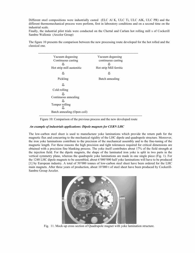
Different steel compositions were industrially casted (ELC Al K, ULC Ti, ULC AlK, ULC PR) and the different thermomechanical process were perform, first in laboratory conditions and on a second time on the industrial scale. Finally, the industrial pilot trials were conducted on the Chertal and Carlam hot rolling mill s of Cockerill Sambre Wallonie (Arcelor Group) The figure 10 presents the comparison between the new processing route developed for the hot rolled and the classical one. ---------------------------------------------------------------------------------------------- Vacuum degassing Vacuum degassing Continuous casting continuous casting Hot strip mill austenitic Hot strip Mill ferritic
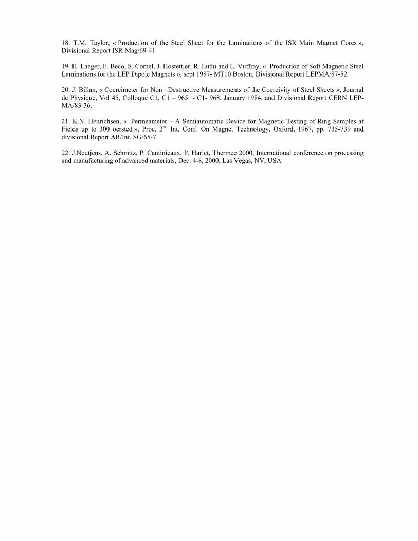
Pickling Batch annealing Cold rolling Continuous annealing Temper rolling Batch annealing (Open coil) ------------------------------------------------------------------------------------------------- Figure 10: Comparison of the previous process and the new developed route An example of industrials applications: Dipole magnets for CERN LHC The low-carbon steel sheet is used to manufacture yoke laminations which provide the return path for the magnetic flux and concurring to the mechanical rigidity of the LHC dipole and quadrupole structure. Moreover, the iron yoke laminations contribute to the precision of the mechanical assembly and to the fine-tuning of the magnetic length. For these reasons the high precision and tight tolerances required for critical dimensions are obtained with a precision fine blanking process. The yoke itself contributes about 17% of the field strength at the injection field. For the dipole magnets, the shape of the laminated iron yoke is split in two parts in the vertical symmetry plane, whereas the quadrupole yoke laminations are made in one single piece (Fig. 1). For the 1248 LHC dipole magnets to be assembled, about 6’000’000 half yoke laminations will have to be produced [1] by European industry. A total of 50’000 tonnes of low-carbon steel sheet have been ordered for the LHC main magnets. After three years of production, about 10’000 t of steel sheet have been produced by Cockerill-Sambre Group Arcelor.
Fig. 11. Mock-up cross section of Quadrupole magnet with yoke lamination structure.

The technical requirements for the low-carbon steel followed closely those defined previously for the ISR, SPS and LEP magnets [2]-[3]. The major differences are related to: - The thickness, which has been increased to 5.8mm with the development of hot rolled material giving the best optimisation between magnetic characteristics of the steel, number of pieces to be fine-blanked and related cost per piece, - the coercivity value, which should remain within a range of ±10A/m with respect to a nominal value of 75A/m. - the flatness, the internal stresses and the thickness spread measured perpendicular to the rolling direction were all defined in view of the tight tolerances to be achieved during the fine blanking process and assembly of the yoke laminations. PRODUCTION PROCESS OF THE STEEL 1. General Aspects The steel production for MAGNETIL BC 5.8 ™, differs with respects to the standard steel production process in the following: - the low impurity content and in particular the remaining carbon content (around 30 ppm) are obtained by transferring the melt after conversion through a vacuum furnace (1600°C, in batches of 150 tonnes) where the alloying elements are also added, - Continuous casting in slabs of about 200 tonnes, - Hot rolling mill with a very tight and precise control of the slabbing and rolling temperature; the size and the homogeneity of the grains structure are obtained and preserved by rolling and cooling the strip at temperatures below the usual range of hot rolling mill operation. The final thickness of the strip is obtained during this operation (5.8mm±0.15), - During the cool-down of the coil, a controlled and stable coating of milling scale if formed with an uniform thickness of 3 to 5 µm (layer of Fe3O4, similar as the blue steaming process), - Final annealing process of the coils under a controlled atmosphere of Nitrogen gas in a bell oven where a grain growth and a grain homogeneity to size ASTM 3 is further obtained. -The finished coils have a weight between 20 and 25 tonnes. 2. Technical Issues During Production The standard production process for the first 1’000 tonnes included a pickling operation performed before the annealing process. This imposed several constrains for the protection against oxidation not only for the produced coils during storage but also after cutting them into sheets. The technical specifications required the sheets to be protected by a thin oil layer, whereas the final fine-blanked yoke laminations had to go through a phosphating coating treatment. In order to optimise the steel manufacturing process and the production costs of the fine-blanked pieces, an intensive study program was initiated by Cockerill-Sambre to check whether the milling scale appearing after the hot rolling operation could be kept as a protection agent against oxidation throughout the production of fine-blanked pieces, thereby avoiding both the oil protection and the expensive phosphating process. The various imposed tests were all successfully completed and resulted in the approval of the process for the further steel sheet production. Moreover, by adding this thin oxide layer into the process, major problems encountered during the initial production phase could be eliminated. These difficulties were mainly related to adherence of the coil layers due to a strong shrinking effect during the annealing process; important coil breaks were developed during the coil unrolling operation destroying thereby the mechanical and magnetic properties of the sheet produced. The sheet cutting and slitting process was performed automatically on a high performance cutting line specially developed and installed for this production. From an initial coil width of 1200 mm, the sheets are slit to a 580 mm width and to a length of 4015 mm. A daily sheet cutting rate of about 150 tonnes of coils could be attained. The sheets are automatically stacked in 3 to 5-ton packets and wrapped with a recyclable multi layer plastic film ready for shipment. The production is organised in campaigns of 800 to 1000 tonnes so to ensure that the steel manufacturing process and the delicate cutting line adjustments could be properly implemented and maintained during the whole production.

As the steel yoke contribution is not a major factor for the magnet field strength, no controlled steel mixing to reduce the spread in remanent field between steel lots has been considered. MECHANICAL AND MAGNETIC MEASUREMENTS The production sequences for the required mechanical and magnetic measurement checks follows a well-defined procedure: - During the sheet cutting process, three sample sheets, with a reduced size (580 mm x 600 mm), are taken in the beginning, the middle and the end of each coil, - Each sample is checked for the flatness and the internal stresses, - The thickness spread is measured over five equidistant positions perpendicular to the rolling direction. For each middle sample of a coil representing the melt, the internal quality assurance checks were extended to systematic measurements of the major chemical components, the grain size, the yield and tensile strength as well as the elongation. Magnetic measurements are performed in two steps: - With a coercimeter [4] the three sheet samples are measured and, in a few minutes, direct values of the coercivity in the longitudinal rolling direction is obtained for each coil. A check is also made on one of the samples in the transverse rolling direction. The limit for the acceptance criteria was set to a maximum coercivity value of 90A/m with respect to a target average value of ~75A/m for the whole steel production. - For the three sample sheets, a circular ring sample was prepared by mean of a water cutting method and used for permeability measurements made with a split coil permeameter [5]. Measurement results are first stored locally in standard EXCEL® spreadsheets and thereafter loaded in a centralised ORACLE ® database structure designed with a Web interface system. RESULTS OF MEASUREMENTS AND STATISTICS 1. MagneticMeasurements Fig. 12 and 13 show respectively the permeability in function of the induction and the magnetisation curve B = f (H). The spread is representative of the minimum and maximum coercivity values recorded with the permeameter.
Fig 12: Relation µ = f (B)
Coercivity and permeability measurements have been performed on three samples taken from each coil and measured at the steel cutting plant. For the permeability measurements, one of the samples was submitted to the total range of magnetic excitation between 18 and 24000 A/m in 29 steps. The two remaining samples were measured at three standard reference excitation points of 40, 1200 and 24000 A/m for which the requested minimum induction was respectively set to values lower or equal to 0.04, 1.5 and 2 Tesla. The influence of ageing on both coercivity and permeability was investigated by submitting one sample for each coil to an accelerated ageing process (150 ºC for 100 h) and then re- measured. In most cases, very little or no variation is observed for the coercivity and the permeability after this process. The coercivity distribution measured on the sample sheets is given in Fig. 4; the peak distribution is presently located in the 80 to 85A/m range.

Fig. 13. Magnetisation curve B= f (H)
As the production process is now well under control, it is expected that in the future, much better and stable characteristic for the magnetic properties will be obtained.
Fig.14. Spread of coercivity taken in
Longitudinal rolling direction 2. Mechanical Characteristics In order to obtain the high precision of the final pieces to be produced, the steel mechanical properties have an important impact on the design of the fine-blanking tools. The limits for the yield and tensile strength were respectively set to >120 N/mm2 (0.2σ) and <300 N/mm2, whereas the thickness spread measured across the rolling width had to be lower than 1.5%. Flatness and internal stresses were fixed so as to limit their influence on the tight geometrical tolerances imposed on the yoke laminations. The distribution obtained for the tensile and yield strength values are shown in Fig. 15 and 16. As rather good and stable values were maintained during the two first years of steel production, the sampling rate could be reduced from one sample per coil to one sample per melt.

Fig. 15:Distribution for the tensile strength
Fig. 16: Distribution for the yield strength
Conclusion This new utilisation of the ferritic rolling in the finishing mill allows to produce a new range of limiting format with rather cheap silicon free magnetic sheets from 1,5 mm up to 10 mm. Other applications as shielding for the protection from magnetic field is now in progress in different industriel applications concerning ferritic hot rolled products as well as cold rolled and annealed steel sheets for thinner gages application.
ACKNOWLEDGMENT The authors would like to thank all the staff involved from CERN Verbeeck, Vlogaert, J. Billan and C.Wyss for their continuing support and encouragement’s throughout this large scale of steel development for LHC project.

REFERENCES 1.Shrabani Majumdar, N. Gope, R. Maheshwari, O.N. Mohanty; Tata search 2000, Tata Steel, Jamshedpur, India 2. S. Babic*, S. Comel*, F. Beckers**, F. Brixhe**, G. Peiro and T. Verbeeck, LHC Division, CERN, Geneva, Switzerland: Towards the production of 50’000 tonnes of low-carbon steel sheet for the LHC superconducting dipole and quadrupole magnets. 3.Messien P., Herman JC, Leroy V. , Harlet Ph., Beco F., Renard L. ; TMS Ferrous Metallurgy Committee, Fall Meeting Cincinnati, oct 22-24 , 1991. 4.Harlet Ph., Beco F., Cantinieaux P., BouquegneauD., Messien P ;, Herman JC., ; Intern. Symp. On Low carbon Steels for the 90’s, Ed . by R. Asfahani & G. Tither. The mineral, Metals & Materials Society, 1993 5.MessienP., Herman JC., Leroy V., Harlet Ph., Huge J., Detry JM., Cantinieaux P. ; Journées ATS Paris ,4-6 décembre 1990. Revue de Metallurgie CIT 433, mai 1991. 6. V Leroy, A. Depaepe, J.C. Herman, International symposium, Modern LC and ULC sheet steels for cold forming : processing and properties, Institute of ferrous Metallography Aachen RWTH, March 30-April 1 1998 7.H. Langer, W Bleck, C. Greisert ; International symposium, Modern LC and ULC sheet steels for cold forming : processing and properties, Institute of ferrous Metallography Aachen RWTH, March 30-April 1 1998 8. H.P. Schmitz, R. Kawalla, M. Espenhahn, K.E. Friedrich , TKS ; International symposium, Modern LC and ULC sheet steels for cold forming : processing and properties, Institute of ferrous Metallography Aachen RWTH, March 30-April 1 1998 9. H. Laeger, F. Beco, S. Comel, J. Hostettler, R. Luthi and L. Vuffray, “Production of Soft Magnetic Steel Laminations for the LEP Dipole Magnets”, Sept. 1987- MT10 Boston, Divisional Report LEP-MA/87-52 10. J.Billan, “Coercimeter for Non-Destructive Measurements of the Coercivity of Steel Sheets”, Journal de Physique, Vol. 45, Colloque C1, C1-965 - C1-968, January 1984, and Divisional Report CERN LEP-MA/83-36 11. K.N. Henrichsen, “Permeameter - A Semiautomatic Device for Magnetic Testing of Ring Samples at Fields up to 300 oersted”, Proc. 2nd Int. Conf. On Magnet Technology, Oxford, 1967, pp 735-739 and Divisional Report AR/Int. SG/65-7. 12. E.P. Wohlfarth, Ferro magnetic Materials, North Holland Publishing, Amsterdam, 1980, p. 83 13. J.K. Stanley,Metallurgy and Magnetism,ASM, Cleveland,1949,p.270 14.F. Bitter , Introduction to Ferro Magnetism, MC Graw Hill , New York, 1937,p.226. 15. S.K. Rau and O.N. Mohanty , Predicting the Extend of magnetic A ging in Electrical steel ,Journal of Magnetism and Magnetic Materials , Vol. 41, 1984. 16. K. Ueno, I. Tachino and T. Kubota, « advantages of vacuum degassing of non – oriented electrical steel » ; Metallurgy of Vacuum-Degassed Steel products, ed R. Pradham ( TMS of AIME , Warrendale, PA), p. 347-354,1990. 17. D. Perini, C. Lanza,P. fessia,T. Verbeeck, « First experience in Mass production of components for the LHC Main dipoles ». Submitted for publication IEEE Trans. Appl Superconductivity.
18. T.M. Taylor, « Production of the Steel Sheet for the Laminations of the ISR Main Magnet Cores », Divisional Report ISR-Mag/69-41 19. H. Laeger, F. Beco, S. Comel, J. Hostettler, R. Luthi and L. Vuffray, « Production of Soft Magnetic Steel Laminations for the LEP Dipole Magnets », sept 1987- MT10 Boston, Divisional Report LEPMA/87-52 20. J. Billan, « Coercimeter for Non –Destructive Measurements of the Coercivity of Steel Sheets », Journal de Physique, Vol 45, Colloque C1, C1 – 965 - C1- 968, January 1984, and Divisional Report CERN LEP-MA/83-36. 21. K.N. Henrichsen, « Permeameter – A Semiautomatic Device for Magnetic Testing of Ring Samples at Fields up to 300 oersted », Proc. 2nd Int. Conf. On Magnet Technology, Oxford, 1967, pp. 735-739 and divisional Report AR/Int. SG/65-7 22. J.Neutjens, A. Schmitz, P. Cantinieaux, P. Harlet, Thermec 2000, International conference on processing and manufacturing of advanced materials, Dec. 4-8, 2000, Las Vegas, NV, USA