Embed Size (px)
Citation preview
A
iUdocfd©
K
1
fphtnalpTmse
dcsep
0d
Available online at www.sciencedirect.com
Electric Power Systems Research 78 (2008) 949–956
New control approach for a PV-diesel autonomous power system
Mohamed Rashed ∗, A. Elmitwally, Sahar KaddahElectrical Engineering Department, Mansoura University, Mansoura 35516, Egypt
Received 7 September 2006; received in revised form 12 May 2007; accepted 5 July 2007Available online 17 August 2007
bstract
A new control scheme for the hybrid photovoltaic-diesel single-phase autonomous power system is proposed. The main advantage of this schemes that the voltage control is accomplished by the interface inverter without need to the automatic voltage regulator of the diesel-driven generator.nlike three-phase systems, frequency and voltage control in single-phase autonomous power systems imposes additional complexity. This isue to the pulsating nature of the single-phase loads instantaneous power at twice the rated frequency that may degrade the control efficacy. Thisbstacle is addressed in this paper and a new scheme is presented. The approach includes three control loops for maximum power tracking, voltage
ontrol and frequency control. The generator field current is held constant at its nominal value avoiding the saturation in the field circuit. A robustuzzy logic controller is adopted for the speed control loop of the diesel engine. The dynamic performance of the system is investigated underifferent operating conditions.2007 Elsevier B.V. All rights reserved.
tbicrhwPhmpai
fcst
eywords: Photovoltaic; Diesel; Autonomous systems; Control; Fuzzy logic
. Introduction
Most conventional energy sources are not environment-riendly and require costly long transmission lines to supplyower to isolated sites. Power supplied to far-off locations causesuge transmission losses and can be much expensive. Therefore,he latest trend is to use distributed power generation along withon-conventional energy sources like photovoltaic (PV), windnd biogas. It can be a better option to save long transmissionines cost. The main advantages of non-conventional sources ofower are no fuel consumption, sustainable and eco-friendly.he major disadvantage with these sources is that they are inter-ittent or fluctuating in nature. To obtain a reliable power supply
ystem, they require integration with other source of power gen-ration forming autonomous/isolated power system [1,2].
For PV power systems, the output power varies randomlyue to fluctuation of solar insolation and climatic conditions. Itompletely disappears during the night hours. There must be a
tand-by power source to meet the load energy demand. Dieselngine driven generators are the most common electrical energyroduction scheme in small and medium size power applica-∗ Corresponding author.E-mail address: [email protected] (M. Rashed).
ikisiol
378-7796/$ – see front matter © 2007 Elsevier B.V. All rights reserved.oi:10.1016/j.epsr.2007.07.003
ions. This is because diesel generators are widely available inroad range from 1 kW to several hundred kilowatts and theres decades of experience in their operation, maintenance andontrol [1–10]. Therefore, PV and diesel systems are incorpo-ated in hybrid systems utilising more than one power source. Aybrid PV and diesel system is quiet reliable because the dieselorks as a compensator to the fluctuating power output of theV array (PVA). Besides, to improve the economic feasibility ofybrid PV-diesel system, there should be a mechanism to extractaximum power of the high cost PVA. Also, due to the output
ower fluctuation of the PVA and load dynamics the frequencynd magnitude of the ac voltage can change accordingly, whichs not desired.
Two control loops are always included to stabilise the voltagerequency and magnitude [5–8]. The first is the load-frequencyontrol loop that caters to maintain the diesel engine rotationalpeed constant, and hence the voltage frequency, regardlesshe output power supplied by the diesel generator. The seconds called automatic voltage regulator (AVR), which works toeep the voltage magnitude constant irrespective of any load-ng dynamics through the control of the field excitation of the
ynchronous diesel generator. The design and tuning of thesentegrated control systems are crucial issues in the operationf hybrid PV-diesel autonomous power system. An extra chal-enge exists when the network is a single-phase ac system (see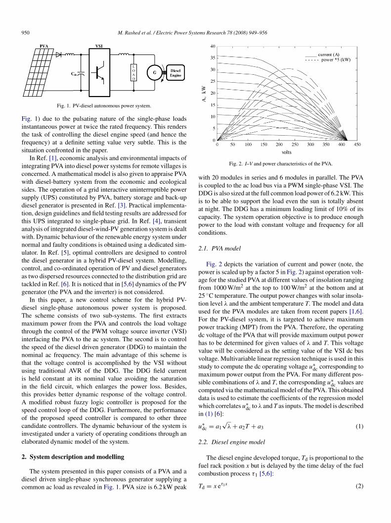
950 M. Rashed et al. / Electric Power Systems Research 78 (2008) 949–956
Fitfs
icwssdttawnutcatg
dTmtitntuiitAsocie
2
dc
wiDiacpc
2
paf2tuFpdhvvsmscdwi
u
2
The diesel engine developed torque, T is proportional to the
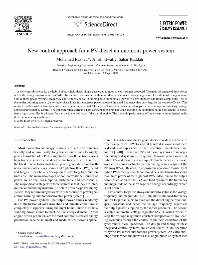
Fig. 1. PV-diesel autonomous power system.
ig. 1) due to the pulsating nature of the single-phase loadsnstantaneous power at twice the rated frequency. This rendershe task of controlling the diesel engine speed (and hence therequency) at a definite setting value very subtle. This is theituation confronted in the paper.
In Ref. [1], economic analysis and environmental impacts ofntegrating PVA into diesel power systems for remote villages isoncerned. A mathematical model is also given to appraise PVAith diesel-battery system from the economic and ecological
ides. The operation of a grid interactive uninterruptible powerupply (UPS) constituted by PVA, battery storage and back-upiesel generator is presented in Ref. [3]. Practical implementa-ion, design guidelines and field testing results are addressed forhis UPS integrated to single-phase grid. In Ref. [4], transientnalysis of integrated diesel-wind-PV generation system is dealtith. Dynamic behaviour of the renewable energy system underormal and faulty conditions is obtained using a dedicated sim-lator. In Ref. [5], optimal controllers are designed to controlhe diesel generator in a hybrid PV-diesel system. Modelling,ontrol, and co-ordinated operation of PV and diesel generatorss two dispersed resources connected to the distribution grid areackled in Ref. [6]. It is noticed that in [5,6] dynamics of the PVenerator (the PVA and the inverter) is not considered.
In this paper, a new control scheme for the hybrid PV-iesel single-phase autonomous power system is proposed.he scheme consists of two sub-systems. The first extractsaximum power from the PVA and controls the load voltage
hrough the control of the PWM voltage source inverter (VSI)nterfacing the PVA to the ac system. The second is to controlhe speed of the diesel driven generator (DDG) to maintain theominal ac frequency. The main advantage of this scheme ishat the voltage control is accomplished by the VSI withoutsing traditional AVR of the DDG. The DDG field currents held constant at its nominal value avoiding the saturationn the field circuit, which enlarges the power loss. Besides,his provides better dynamic response of the voltage control.
modified robust fuzzy logic controller is proposed for thepeed control loop of the DDG. Furthermore, the performancef the proposed speed controller is compared to other threeandidate controllers. The dynamic behaviour of the system isnvestigated under a variety of operating conditions through anlaborated dynamic model of the system.
. System description and modelling
The system presented in this paper consists of a PVA and aiesel driven single-phase synchronous generator supplying aommon ac load as revealed in Fig. 1. PVA size is 6.2 kW peak
fc
T
Fig. 2. I–V and power characteristics of the PVA.
ith 20 modules in series and 6 modules in parallel. The PVAs coupled to the ac load bus via a PWM single-phase VSI. TheDG is also sized at the full common load power of 6.2 kW. This
s to be able to support the load even the sun is totally absentt night. The DDG has a minimum loading limit of 10% of itsapacity. The system operation objective is to produce enoughower to the load with constant voltage and frequency for allonditions.
.1. PVA model
Fig. 2 depicts the variation of current and power (note, theower is scaled up by a factor 5 in Fig. 2) against operation volt-ge for the studied PVA at different values of insolation rangingrom 1000 W/m2 at the top to 100 W/m2 at the bottom and at5 ◦C temperature. The output power changes with solar insola-ion level λ and the ambient temperature T. The model and datased for the PVA modules are taken from recent papers [1,6].or the PV-diesel system, it is targeted to achieve maximumower tracking (MPT) from the PVA. Therefore, the operatingc voltage of the PVA that will provide maximum output poweras to be determined for given values of λ and T. This voltagealue will be considered as the setting value of the VSI dc busoltage. Multivariable linear regression technique is used in thistudy to compute the dc operating voltage u∗
dc corresponding toaximum power output from the PVA. For many different pos-
ible combinations of λ and T, the corresponding u∗dc values are
omputed via the mathematical model of the PVA. This obtainedata is used to estimate the coefficients of the regression modelhich correlates u∗
dc to λ and T as inputs. The model is describedn (1) [6]:
∗dc = a1
√λ + a2T + a3 (1)
.2. Diesel engine model
duel rack position x but is delayed by the time delay of the fuelombustion process τ1 [5,6]:
d = x eτ1s (2)
Syste
tτ
x
T
2
ctdgs
3
sa
3
mvbtbdmaTds
ortbu
ecsavcpVrc
i
wω
lwaa
pbtptsoa
M. Rashed et al. / Electric Power
The fuel rack position is proportional to the applied referenceorque T ∗
d , but delayed by the electro-hydraulic time constant,2:
= T ∗d
1 + τ2s(3)
he model of the diesel engine is built using (2) and (3).
.3. Synchronous generator model
The used generator is a single-phase cylindrical type syn-hronous machine where the following assumptions are made:he field current is constant, the air gap flux is sinusoidalyistributed and saturation is negligible. Thus, the synchronousenerator is modelled in its simple form as a single-phase voltageource with constant internal impedance.
. Proposed control scheme
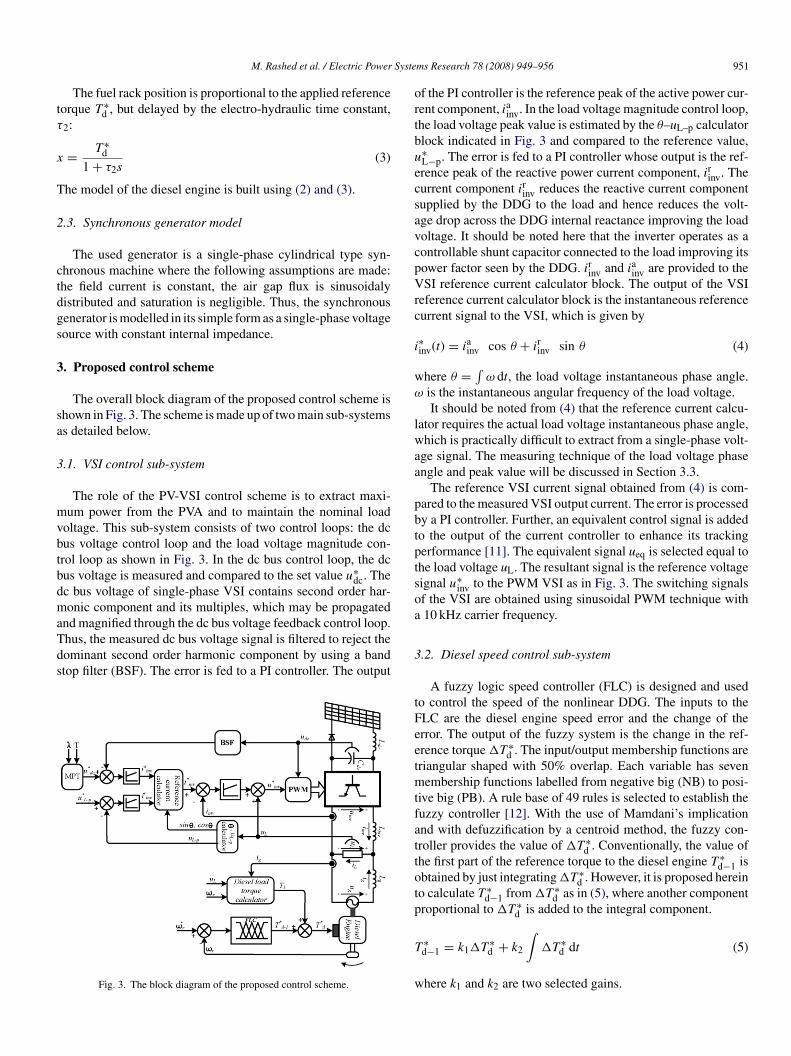
The overall block diagram of the proposed control scheme ishown in Fig. 3. The scheme is made up of two main sub-systemss detailed below.
.1. VSI control sub-system
The role of the PV-VSI control scheme is to extract maxi-um power from the PVA and to maintain the nominal load
oltage. This sub-system consists of two control loops: the dcus voltage control loop and the load voltage magnitude con-rol loop as shown in Fig. 3. In the dc bus control loop, the dcus voltage is measured and compared to the set value u∗
dc. Thec bus voltage of single-phase VSI contains second order har-onic component and its multiples, which may be propagated
nd magnified through the dc bus voltage feedback control loop.hus, the measured dc bus voltage signal is filtered to reject theominant second order harmonic component by using a bandtop filter (BSF). The error is fed to a PI controller. The output
Fig. 3. The block diagram of the proposed control scheme.
3
tFeetmtfattotp
T
w
ms Research 78 (2008) 949–956 951
f the PI controller is the reference peak of the active power cur-ent component, iainv. In the load voltage magnitude control loop,he load voltage peak value is estimated by the θ–uL–p calculatorlock indicated in Fig. 3 and compared to the reference value,∗L−p. The error is fed to a PI controller whose output is the ref-rence peak of the reactive power current component, irinv. Theurrent component irinv reduces the reactive current componentupplied by the DDG to the load and hence reduces the volt-ge drop across the DDG internal reactance improving the loadoltage. It should be noted here that the inverter operates as aontrollable shunt capacitor connected to the load improving itsower factor seen by the DDG. irinv and iainv are provided to theSI reference current calculator block. The output of the VSI
eference current calculator block is the instantaneous referenceurrent signal to the VSI, which is given by
∗inv(t) = iainv cos θ + irinv sin θ (4)
here θ = ∫ω dt, the load voltage instantaneous phase angle.
is the instantaneous angular frequency of the load voltage.It should be noted from (4) that the reference current calcu-
ator requires the actual load voltage instantaneous phase angle,hich is practically difficult to extract from a single-phase volt-
ge signal. The measuring technique of the load voltage phasengle and peak value will be discussed in Section 3.3.
The reference VSI current signal obtained from (4) is com-ared to the measured VSI output current. The error is processedy a PI controller. Further, an equivalent control signal is addedo the output of the current controller to enhance its trackingerformance [11]. The equivalent signal ueq is selected equal tohe load voltage uL. The resultant signal is the reference voltageignal u∗
inv to the PWM VSI as in Fig. 3. The switching signalsf the VSI are obtained using sinusoidal PWM technique with10 kHz carrier frequency.
.2. Diesel speed control sub-system
A fuzzy logic speed controller (FLC) is designed and usedo control the speed of the nonlinear DDG. The inputs to theLC are the diesel engine speed error and the change of therror. The output of the fuzzy system is the change in the ref-rence torque �T ∗
d . The input/output membership functions areriangular shaped with 50% overlap. Each variable has sevenembership functions labelled from negative big (NB) to posi-
ive big (PB). A rule base of 49 rules is selected to establish theuzzy controller [12]. With the use of Mamdani’s implicationnd with defuzzification by a centroid method, the fuzzy con-roller provides the value of �T ∗
d . Conventionally, the value ofhe first part of the reference torque to the diesel engine T ∗
d−1 isbtained by just integrating �T ∗
d . However, it is proposed hereino calculate T ∗
d−1 from �T ∗d as in (5), where another component
roportional to �T ∗d is added to the integral component.
∗d−1 = k1�T ∗
d + k2
∫�T ∗
d dt (5)
here k1 and k2 are two selected gains.
9 Syste
tattts
T
wca
efpra
sdsp
Tmat1mputss
3
is
u
u
f5
u
c
ptv(ti
4
puitusaeRTf
4
i5Tpv(iiilasFPVA MPT. It is changed to 235 V at 0.3 s to follow the new ref-erence value specified by the PVA MPT. The situation at the last0.3 s period (restoration of full insolation) is similar to its coun-terpart at the first 0.3 s. The filtered dc voltage (involved in the
Table 1System parameters used in simulation
DDG side Voltage: 110 V (rms); No. of poles = 4; X = 0.471 �;Ra = 0.1 �; total system inertia = 0.3 kg m2;τ1 = 15 ms; τ2 = 6 ms
PVA side Reactor, Ldc = 1 mH; a1 = 0.556; a2 = −0.588 and
52 M. Rashed et al. / Electric Power
The proportional component in (5) is introduced to improvehe controller tuning and the transient response of the system. Inddition, it is thought that with the inclusion of the proportionalerm in (5), the performance of the proposed controller will havehe features of the fuzzy PID controller. The dummy derivativeerm is eligible to improve the dynamic response of such DDGystems with considerably large inertia and time delay.
The load torque Tl of the DDG is estimated by
l = (uL + Raig) ig
ωr
+ Bωr (6)
here Ra is the generator armature resistance (�) B is the frictionoefficient of the DDG, (N m s) ig is the generator current (A)nd ωr is the diesel engine angular speed (rad/s).
It should be noted in (6) that the reactance term is not consid-red because it does not contribute to the generator active powerrom which the torque is computed. So it is removed for sim-licity. Moreover, it is a common practice in implementation ofeal systems to avoid the derivative terms whenever possible as itmplifies the system noise and may lead to instability problems.
Tl is fed forward and added to T ∗d−1 as an equivalent control
ignal to enhance the capability of the diesel engine to reject loadisturbances [7]. The resultant output is the reference torqueignal T ∗
d to the governor of the diesel engine, which should beractically smooth at steady-state.
It should be noted from (6) that the instantaneous load torquel contains pulsating torque components of second-order and itsultiples (since the DDG is single phase). Because Tl is added
s equivalent control signal to the output of the FLC, the resul-ant torque T ∗
d may contain pulsating components. BSF tuned at00 Hz is employed to eliminate the dominant second order har-onic component of Tl before adding to T ∗
d−1. Furthermore, theulsating nature of Tl produces speed ripples and consequentlynwanted voltage harmonics. The speed ripples are propagatedhrough the diesel speed control loop and may distort the T ∗
dignal. BSF tuned at 100 Hz is used to filter out the dominantecond-order harmonic component of the speed signal.
.3. Load voltage phasor tracking
To estimate the load voltage phase angle and peak value,t is proposed that the measured load voltage signal is the co-inusoidal voltage component uL–d:
L−d (t) = uL (t) (7)
The sinusoidal voltage component uL–q is obtained as
L−q(t) = 2πf
∫uL(t) dt (8)
is set constant and equal to the nominal system frequency,0 Hz.
The peak voltage uL–p and the phase angle θ are computed as
L−p(t) =√
u2L−q(t) + u2
L−d(t) (9)
V
L
ms Research 78 (2008) 949–956
os θ = uL−d(t)
u∗L−p
, sin θ = uL−q(t)
u∗L−p
(10)
The assumed constant value of f in (8) makes the estimatedeak voltage uL–p and the phase angle θ just good approximateo the real state. It is noted that the reference value of the peakoltage is used in (10) instead of the actual value provided by9) in order to reduce the effect of system noise. This is becausehe reference signal is always smooth and free of ripples. Also,t has a very close value to the actual value in (9).
. Results and discussion
The PV-diesel hybrid system shown in Fig. 1 with the pro-osed control scheme discussed in Section 3 is investigatednder different operating conditions. The system is simulatedn Matlab environment to investigate its dynamic behaviour andhe integrity of the proposed scheme. The power system sim-lator, SimPowerSystems toolbox and Simulink are used forystem modelling and simulation. The used PWM VSI is a tworm IGBT/Diode universal bridge inverter provided in SimPow-rSystems toolbox. The load is modelled as a single-phase seriesL load. The system parameters used in simulation are listed inable 1. Three operation cases are studied and described in theollowing sub-sections.
.1. Step change in insolation
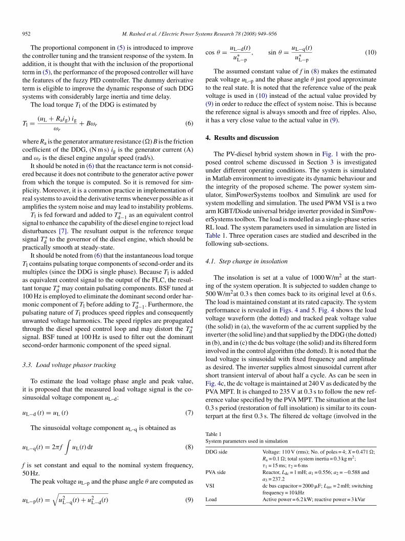
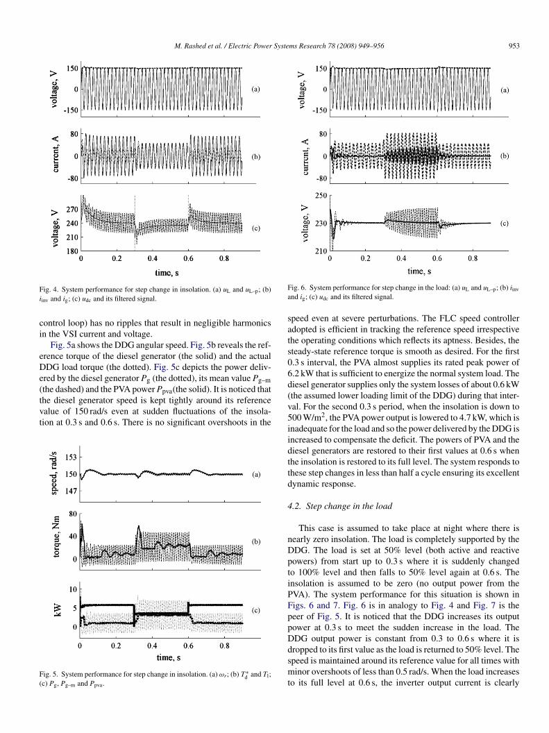
The insolation is set at a value of 1000 W/m2 at the start-ng of the system operation. It is subjected to sudden change to00 W/m2at 0.3 s then comes back to its original level at 0.6 s.he load is maintained constant at its rated capacity. The systemerformance is revealed in Figs. 4 and 5. Fig. 4 shows the loadoltage waveform (the dotted) and tracked peak voltage valuethe solid) in (a), the waveform of the ac current supplied by thenverter (the solid line) and that supplied by the DDG (the dotted)n (b), and in (c) the dc bus voltage (the solid) and its filtered formnvolved in the control algorithm (the dotted). It is noted that theoad voltage is sinusoidal with fixed frequency and amplitudes desired. The inverter supplies almost sinusoidal current afterhort transient interval of about half a cycle. As can be seen inig. 4c, the dc voltage is maintained at 240 V as dedicated by the
a3 = 237.2SI dc bus capacitor = 2000 �F; Linv = 2 mH; switching
frequency = 10 kHzoad Active power = 6.2 kW; reactive power = 3 kVar
M. Rashed et al. / Electric Power Systems Research 78 (2008) 949–956 953
Fi
ci
eDe(tvt
F(
Fa
sats06d
ig. 4. System performance for step change in insolation. (a) uL and uL–p; (b)
inv and ig; (c) udc and its filtered signal.
ontrol loop) has no ripples that result in negligible harmonicsn the VSI current and voltage.
Fig. 5a shows the DDG angular speed. Fig. 5b reveals the ref-rence torque of the diesel generator (the solid) and the actualDG load torque (the dotted). Fig. 5c depicts the power deliv-
red by the diesel generator Pg (the dotted), its mean value Pg–m
the dashed) and the PVA power Ppva(the solid). It is noticed thathe diesel generator speed is kept tightly around its referencealue of 150 rad/s even at sudden fluctuations of the insola-ion at 0.3 s and 0.6 s. There is no significant overshoots in theig. 5. System performance for step change in insolation. (a) ωr; (b) T ∗d and Tl;
c) Pg, Pg–m and Ppva.
(v5iidttd
4
nDptiPFppDdsmt
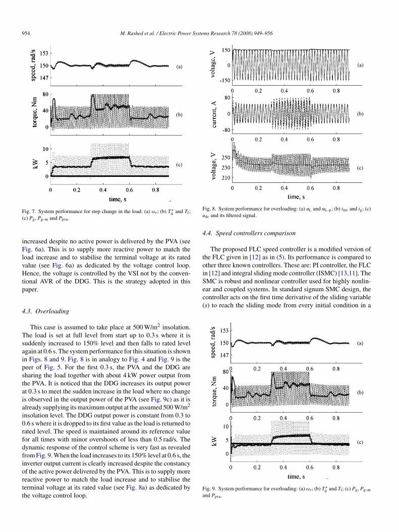
ig. 6. System performance for step change in the load: (a) uL and uL–p; (b) iinv
nd ig; (c) udc and its filtered signal.
peed even at severe perturbations. The FLC speed controllerdopted is efficient in tracking the reference speed irrespectivehe operating conditions which reflects its aptness. Besides, theteady-state reference torque is smooth as desired. For the first.3 s interval, the PVA almost supplies its rated peak power of.2 kW that is sufficient to energize the normal system load. Theiesel generator supplies only the system losses of about 0.6 kWthe assumed lower loading limit of the DDG) during that inter-al. For the second 0.3 s period, when the insolation is down to00 W/m2, the PVA power output is lowered to 4.7 kW, which isnadequate for the load and so the power delivered by the DDG isncreased to compensate the deficit. The powers of PVA and theiesel generators are restored to their first values at 0.6 s whenhe insolation is restored to its full level. The system responds tohese step changes in less than half a cycle ensuring its excellentynamic response.
.2. Step change in the load
This case is assumed to take place at night where there isearly zero insolation. The load is completely supported by theDG. The load is set at 50% level (both active and reactiveowers) from start up to 0.3 s where it is suddenly changedo 100% level and then falls to 50% level again at 0.6 s. Thensolation is assumed to be zero (no output power from theVA). The system performance for this situation is shown inigs. 6 and 7. Fig. 6 is in analogy to Fig. 4 and Fig. 7 is theeer of Fig. 5. It is noticed that the DDG increases its outputower at 0.3 s to meet the sudden increase in the load. TheDG output power is constant from 0.3 to 0.6 s where it is
ropped to its first value as the load is returned to 50% level. Thepeed is maintained around its reference value for all times withinor overshoots of less than 0.5 rad/s. When the load increaseso its full level at 0.6 s, the inverter output current is clearly
954 M. Rashed et al. / Electric Power Systems Research 78 (2008) 949–956
F(
iFlvHtp
4
Tsaipstaiai0rfdfiortt
Fu
4
toiSear and coupled systems. In standard signum SMC design, thecontroller acts on the first time derivative of the sliding variable(s) to reach the sliding mode from every initial condition in a
ig. 7. System performance for step change in the load: (a) ωr; (b) T ∗d and Tl;
c) Pg, Pg–m and Ppva.
ncreased despite no active power is delivered by the PVA (seeig. 6a). This is to supply more reactive power to match the
oad increase and to stabilise the terminal voltage at its ratedalue (see Fig. 6a) as dedicated by the voltage control loop.ence, the voltage is controlled by the VSI not by the conven-
ional AVR of the DDG. This is the strategy adopted in thisaper.
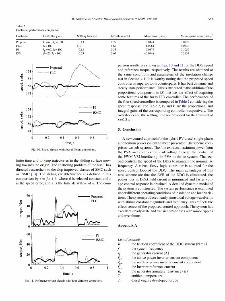
.3. Overloading
This case is assumed to take place at 500 W/m2 insolation.he load is set at full level from start up to 0.3 s where it isuddenly increased to 150% level and then falls to rated levelgain at 0.6 s. The system performance for this situation is shownn Figs. 8 and 9. Fig. 8 is in analogy to Fig. 4 and Fig. 9 is theeer of Fig. 5. For the first 0.3 s, the PVA and the DDG areharing the load together with about 4 kW power output fromhe PVA. It is noticed that the DDG increases its output powert 0.3 s to meet the sudden increase in the load where no changes observed in the output power of the PVA (see Fig. 9c) as it islready supplying its maximum output at the assumed 500 W/m2
nsolation level. The DDG output power is constant from 0.3 to.6 s where it is dropped to its first value as the load is returned toated level. The speed is maintained around its reference valueor all times with minor overshoots of less than 0.5 rad/s. Theynamic response of the control scheme is very fast as revealedrom Fig. 9. When the load increases to its 150% level at 0.6 s, the
nverter output current is clearly increased despite the constancyf the active power delivered by the PVA. This is to supply moreeactive power to match the load increase and to stabilise theerminal voltage at its rated value (see Fig. 8a) as dedicated byhe voltage control loop.Fa
ig. 8. System performance for overloading: (a) uL and uL–p; (b) iinv and ig; (c)
dc and its filtered signal.
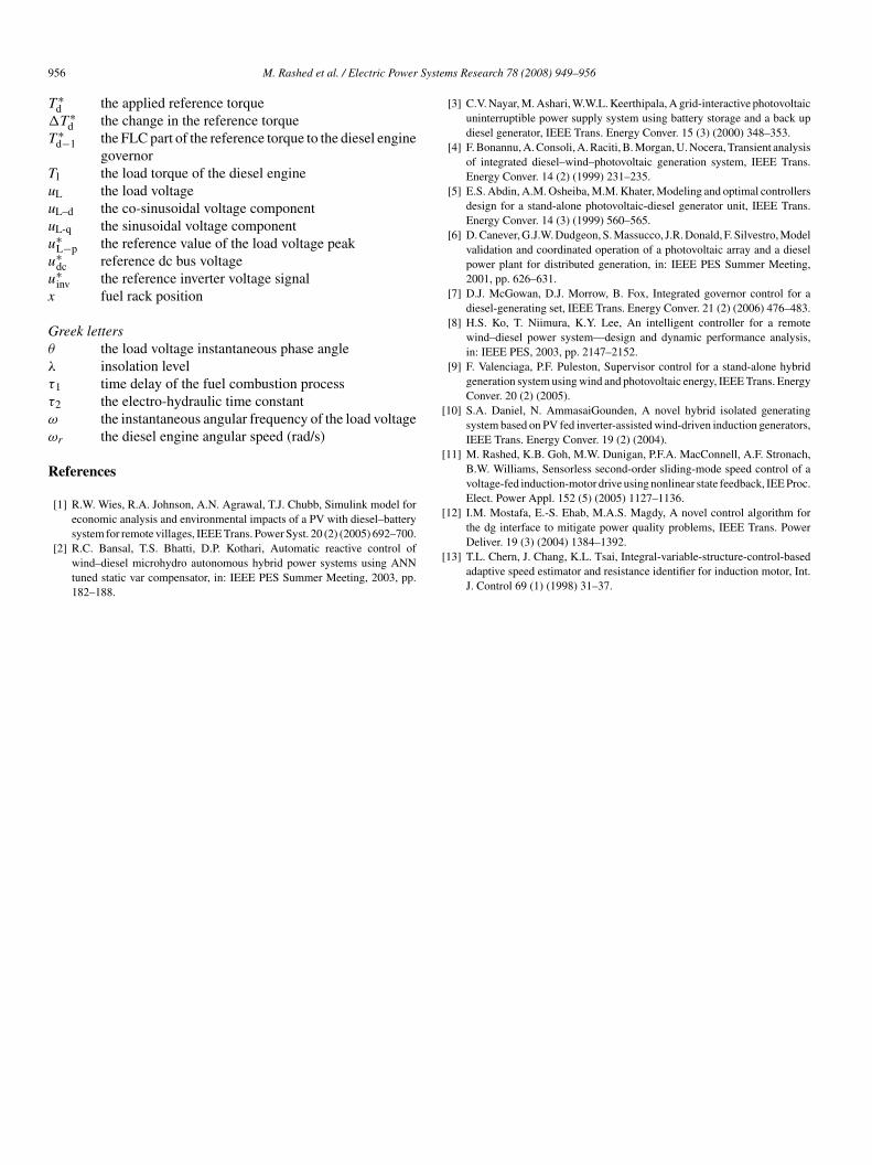
.4. Speed controllers comparison
The proposed FLC speed controller is a modified version ofhe FLC given in [12] as in (5). Its performance is compared tother three known controllers. These are: PI controller, the FLCn [12] and integral sliding mode controller (ISMC) [13,11]. TheMC is robust and nonlinear controller used for highly nonlin-
ig. 9. System performance for overloading: (a) ωr; (b) T ∗d and Tl; (c) Pg, Pg–m
nd Ppva.
M. Rashed et al. / Electric Power Systems Research 78 (2008) 949–956 955
Table 2Controller performance comparison
Controller Controller gains Settling time (s) Overshoots (%) Mean error (rad/s) Mean square error (rad/s)2
Proposed k1 = 60, k2 = 100 0.13 0.27 0.0441 0.0820FLC ki = 100 >0.3 1.67PI kp = 60, ki = 100 0.13 0.33ISM β = 20, ki = 100 0.23 0.67
fiidaci
pattcspstsiot
5
apttofs
Fig. 10. Speed signals with four different controllers.
nite time and to keep trajectories in the sliding surface mov-ng towards the origin. The chattering problem of the SMC hasirected researchers to develop improved classes of SMC such
s ISMC [13]. The sliding variable/surface s is defined in thisomparison by s = βe + e, where β is selected constant and es the speed error, and e is the time derivative of e. The com-Fig. 11. Reference torque signals with four different controllers.
npatutweea
A
LBfii
i
i
RTT
1.0061 6.07300.0674 0.1050
−0.0948 0.2134
arison results are shown in Figs. 10 and 11 for the DDG speednd reference torque, respectively. The results are obtained athe same conditions and parameters of the insolation changeest in Section 4.1. It is worthy noting that the proposed speedontroller is superior to its counterparts. It has best dynamic andteady-state performance. This is attributed to the addition of theroportional component in (5) that has the effect of acquiringome features of the fuzzy PID controller. The performance ofhe four speed controllers is compared in Table 2 considering thepeed response. For Table 2, kp and ki are the proportional andntegral gains of the corresponding controller, respectively. Thevershoots and the settling time are provided for the transient at= 0.3 s.
. Conclusion
A new control approach for the hybrid PV-diesel single-phaseutonomous power system has been presented. The scheme com-rises two sub-systems. The first extracts maximum power fromhe PVA and controls the load voltage through the control ofhe PWM VSI interfacing the PVA to the ac system. The sec-nd controls the speed of the DDG to maintain the nominal acrequency. A robust fuzzy logic controller is adopted for thepeed control loop of the DDG. The main advantages of thisew scheme are that the AVR of the DDG is eliminated, theower loss in DDG field circuit is minimized and faster volt-ge control response is obtained. A detailed dynamic model ofhe system is constructed. The system performance is examinednder different operating conditions of insolation and load varia-ions. The system produces nearly sinusoidal voltage waveformsith almost constant magnitude and frequency. This reflects the
ffectiveness of the proposed control approach. The system hasxcellent steady-state and transient responses with minor ripplesnd overshoots.
ppendix A
ist of symbolsthe friction coefficient of the DDG system (N m s)the system frequency
g the generator current (A)ainv the active power inverter current componentrinv the reactive power inverter current component
∗inv the inverter reference currenta the generator armature resistance (�)ambient temperatured diesel engine developed torque
9 Syste
T
�
T
Tuuuu
u
u
x
Gθ
λ
τ
τ
ω
ω
R
[
[
[
56 M. Rashed et al. / Electric Power
∗d the applied reference torqueT ∗
d the change in the reference torque∗d−1 the FLC part of the reference torque to the diesel engine
governorl the load torque of the diesel engineL the load voltageL–d the co-sinusoidal voltage componentL-q the sinusoidal voltage component∗L−p the reference value of the load voltage peak∗dc reference dc bus voltage∗inv the reference inverter voltage signal
fuel rack position
reek lettersthe load voltage instantaneous phase angleinsolation level
1 time delay of the fuel combustion process2 the electro-hydraulic time constant
the instantaneous angular frequency of the load voltager the diesel engine angular speed (rad/s)
eferences
[1] R.W. Wies, R.A. Johnson, A.N. Agrawal, T.J. Chubb, Simulink model foreconomic analysis and environmental impacts of a PV with diesel–battery
system for remote villages, IEEE Trans. Power Syst. 20 (2) (2005) 692–700.[2] R.C. Bansal, T.S. Bhatti, D.P. Kothari, Automatic reactive control ofwind–diesel microhydro autonomous hybrid power systems using ANNtuned static var compensator, in: IEEE PES Summer Meeting, 2003, pp.182–188.
[
ms Research 78 (2008) 949–956
[3] C.V. Nayar, M. Ashari, W.W.L. Keerthipala, A grid-interactive photovoltaicuninterruptible power supply system using battery storage and a back updiesel generator, IEEE Trans. Energy Conver. 15 (3) (2000) 348–353.
[4] F. Bonannu, A. Consoli, A. Raciti, B. Morgan, U. Nocera, Transient analysisof integrated diesel–wind–photovoltaic generation system, IEEE Trans.Energy Conver. 14 (2) (1999) 231–235.
[5] E.S. Abdin, A.M. Osheiba, M.M. Khater, Modeling and optimal controllersdesign for a stand-alone photovoltaic-diesel generator unit, IEEE Trans.Energy Conver. 14 (3) (1999) 560–565.
[6] D. Canever, G.J.W. Dudgeon, S. Massucco, J.R. Donald, F. Silvestro, Modelvalidation and coordinated operation of a photovoltaic array and a dieselpower plant for distributed generation, in: IEEE PES Summer Meeting,2001, pp. 626–631.
[7] D.J. McGowan, D.J. Morrow, B. Fox, Integrated governor control for adiesel-generating set, IEEE Trans. Energy Conver. 21 (2) (2006) 476–483.
[8] H.S. Ko, T. Niimura, K.Y. Lee, An intelligent controller for a remotewind–diesel power system—design and dynamic performance analysis,in: IEEE PES, 2003, pp. 2147–2152.
[9] F. Valenciaga, P.F. Puleston, Supervisor control for a stand-alone hybridgeneration system using wind and photovoltaic energy, IEEE Trans. EnergyConver. 20 (2) (2005).
10] S.A. Daniel, N. AmmasaiGounden, A novel hybrid isolated generatingsystem based on PV fed inverter-assisted wind-driven induction generators,IEEE Trans. Energy Conver. 19 (2) (2004).
11] M. Rashed, K.B. Goh, M.W. Dunigan, P.F.A. MacConnell, A.F. Stronach,B.W. Williams, Sensorless second-order sliding-mode speed control of avoltage-fed induction-motor drive using nonlinear state feedback, IEE Proc.Elect. Power Appl. 152 (5) (2005) 1127–1136.
12] I.M. Mostafa, E.-S. Ehab, M.A.S. Magdy, A novel control algorithm for
the dg interface to mitigate power quality problems, IEEE Trans. PowerDeliver. 19 (3) (2004) 1384–1392.13] T.L. Chern, J. Chang, K.L. Tsai, Integral-variable-structure-control-basedadaptive speed estimator and resistance identifier for induction motor, Int.J. Control 69 (1) (1998) 31–37.