Embed Size (px)
Citation preview

KSF
Compact seriesCompact Series
NEW
For details, visit THK at www.thk.com Product information is updated regularly on the THK website.
New KSF10 Size, Now AvailableTop Cover Type / Open Cover Type Lineup
CATALOG No.385-7E

Compact Series KSF
Controller series
Lineup
Top Cover Type Open Cover TypeFully Enclosed TypeWith motor
Directly coupled: From P.15Motor wrapped: From P.17
Directly coupled: From P.71Motor wrapped: From P.73
P140 P151
Directly coupled: From P.35Motor wrapped: From P.37
Directly coupled: From P.51Motor wrapped: From P.53
Directly coupled: From P.91Motor wrapped: From P.93
Directly coupled: From P.107Motor wrapped: From P.109
Without motor
Directly coupMotor wrapp
Directly coupleMotor wrapped
Directly coMotor wra
Directly coMotor wrap
h motor
out motor
THC TNU/TJU
2
ELECTRIC ACTUATORSCompact series
THC
TNU/TJU
KSF8
KSF4
KSF5
KSF6
KSF 10T
KSF10
KSF 5T
KSF 6T
KSF 8T
KSF 10U
KSF 4U
KSF 5U
KSF 6U
KSF 8U
Fea
ture
sP
rod
uct
Line
upM
odel
C
onfig
urat
ion
Spec
ifica
tions
/ D
imen
sion
sTe
ch
nic
al
Ma
teri
als
Features ……………………………………… 3Product Lineup ……………………………… 9Model Configuration …………………………11
Specifications / DimensionsFully Enclosed Type / THC Specifications
15
17
19
21
23
25
27
29
31
33
Top Cover Type / THC Specifications35
37
39
Open Cover Type / THC Specifications51
53
55
57
59
Fully Enclosed Type / Without Motor Specification
71
73
75
77
79
Top Cover Type / Without Motor Specification91
93
95
97
99
Open Cover Type / Without Motor Specification
111
113
115
117
119
121
123
125
Option127
131
131
133
Controller
151
KSF technical materials …………………… 153
Contents
3
ELECTRIC ACTUATORS Compact seriesF
eatu
res
Pro
duc
t Li
neup
Mod
el
Con
figur
atio
nSp
ecifi
catio
ns /
Dim
ensi
ons
Tec
hn
ica
l M
ate
ria
ls
KSF8
KSF4
KSF5
KSF6
KSF 10T
KSF10
KSF 5T
KSF 6T
KSF 8T
KSF 10U
KSF 4U
KSF 5U
KSF 6U
KSF 8U
TNU/TJU
THC
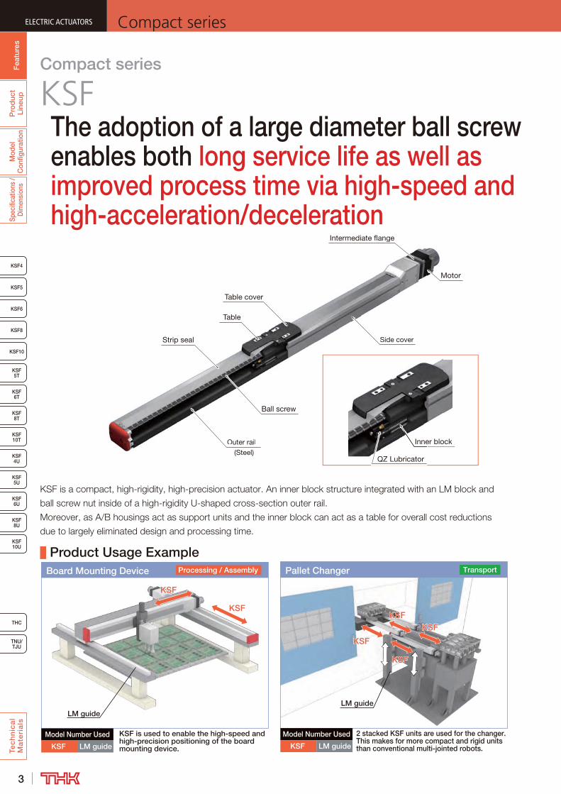
Table cover
Strip seal
Outer rail
(Steel)
Outer rail
Side coverSide cover
MotorMotorM
Intermediate flange
Ball screwBall screw
Inner blockocker blo
QZ Lubricator
Inne
QZ LubricatorQ
Table
The adoption of a large diameter ball screw enables both long service life as well as improved process time via high-speed and high-acceleration/deceleration
Compact series
KSF
KSFKSF
KSFKSF
Model Number Used
KSF LM guide
LM guide
Board Mounting Device Processing / Assembly
KSF is used to enable the high-speed and high-precision positioning of the board mounting device.
Pallet Changer
KSFKSF
KSFKSFKSFKSF
KSFKSF
Transport
Model Number Used
KSF LM guide
LM guide
2 stacked KSF units are used for the changer. This makes for more compact and rigid units than conventional multi-jointed robots.
Product Usage Example
4
ELECTRIC ACTUATORSCompact series
Fea
ture
sP
rod
uct
Line
upM
odel
C
onfig
urat
ion
Spec
ifica
tions
/ D
imen
sion
sTe
ch
nic
al
Ma
teri
als
THC
TNU/TJU
KSF8
KSF4
KSF5
KSF6
KSF 10T
KSF10
KSF 5T
KSF 6T
KSF 8T
KSF 10U
KSF 4U
KSF 5U
KSF 6U
KSF 8U
0
2
4
6
8
0 1 2 3 4 5 6 7 8
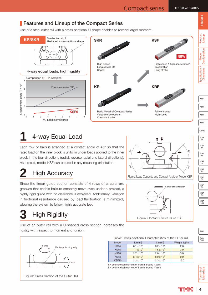
MC Load moment [N·m]
Dis
pla
cem
ent
angl
e [°
] x10
-2
Comparison of THK samples
KSF6
Economy series ES6
Steel outer rail of U-shaped cross-sectional shape
4-way equal loads, high rigidity
KR/SKR
Features and Lineup of the Compact Series
KR
Basic Model of Compact SeriesVersatile size optionsConsistent seller
KRF
Fully enclosedHigh speed
SKR
High SpeedLong service lifeCaged
KSF
High speed & high acceleration/decelerationLong stroke
NEW
2 High Accuracy
3 High Rigidity
1 4-way Equal Load45
°45
°
45°45°
Center of ball rotation
Model IX[mm4] IY[mm4] Weight [kg/m]KSF4 6.1 x 10³ 6.2 x 10⁴ 2.6KSF5 1.7 x 10⁴ 1.5 x 10⁵ 3.9KSF6 2.7 x 10⁴ 2.8 x 10⁵ 5.0KSF8 8.4 x 10⁴ 8.9 x 10⁵ 9.0
KSF10 2.2 x 10⁵ 2.3 x 10⁶ 15.0
lX= geometrical moment of inertia around X axislY= geometrical moment of inertia around Y axis
Center point of gravityY axis
X axis
5
ELECTRIC ACTUATORS Compact seriesF
eatu
res
Pro
duc
t Li
neup
Mod
el
Con
figur
atio
nSp
ecifi
catio
ns /
Dim
ensi
ons
Tec
hn
ica
l M
ate
ria
ls
KSF8
KSF4
KSF5
KSF6
KSF 10T
KSF10
KSF 5T
KSF 6T
KSF 8T
KSF 10U
KSF 4U
KSF 5U
KSF 6U
KSF 8U
TNU/TJU
THC
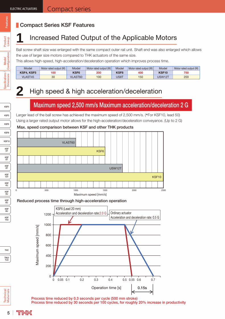
Model Motor rated output (W) Model Motor rated output (W) Model Motor rated output (W) Model Motor rated output (W)KSF4, KSF5 100 KSF6 200 KSF8 400 KSF10 750
VLAST45 30 VLAST60 100 US8T 150 USW12T 200
Compact Series KSF Features
1 Increased Rated Output of the Applicable Motors
2 High speed & high acceleration/deceleration
Maximum speed 2,500 mm/s Maximum acceleration/deceleration 2 G
0 500 1000 1500 2000 2500
KSF10
USW12T
KSF6
VLAST60
Maximum speed [mm/s]
Max. speed comparison between KSF and other THK products
Reduced process time through high-acceleration operation
Operation time [s]
Max
imum
sp
eed
[mm
/s]
0
200
400
600
800
1000
1200
0 0.05 0.1 0.2 0.3 0.4 0.5 0.55 0.6 0.7
0.15s
KSF6 (Lead 20 mm)Acceleration and deceleration rate:2.0 G Ordinary actuator
Acceleration and deceleration rate: 0.5 G
Process time reduced by 0.3 seconds per cycle (500 mm stroke)Process time reduced by 30 seconds per 100 cycles, for roughly 20% increase in productivity

6
ELECTRIC ACTUATORSCompact series
Fea
ture
sP
rod
uct
Line
upM
odel
C
onfig
urat
ion
Spec
ifica
tions
/ D
imen
sion
sTe
ch
nic
al
Ma
teri
als
THC
TNU/TJU
KSF8
KSF4
KSF5
KSF6
KSF 10T
KSF10
KSF 5T
KSF 6T
KSF 8T
KSF 10U
KSF 4U
KSF 5U
KSF 6U
KSF 8U
3 Long service life
Running life comparison between KSF and other THK products
20,000 km
Stroke: 500 mm
KSF4
Max. stroke is 1.8 times
Stroke: 900 mm
VLAST45
4 Long stroke Maximum stroke 1,500 mm
KSF8
US8T
KSF10
USW12T
KSF6
VLAST60
Stroke [mm]
VLAST45
KSF4, 5
0 100 200 300 400 500 600 700 800 900 1000 1100 1200 1300 1400 1500 1600
Max. stroke comparison between KSF and other THK products
KSF8
US8T
KSF6
VLAST60
0 5000 10000 15000 20000
Running life [km]
7
ELECTRIC ACTUATORS Compact seriesF
eatu
res
Pro
duc
t Li
neup
Mod
el
Con
figur
atio
nSp
ecifi
catio
ns /
Dim
ensi
ons
Tec
hn
ica
l M
ate
ria
ls
KSF8
KSF4
KSF5
KSF6
KSF 10T
KSF10
KSF 5T
KSF 6T
KSF 8T
KSF 10U
KSF 4U
KSF 5U
KSF 6U
KSF 8U
TNU/TJU
THC
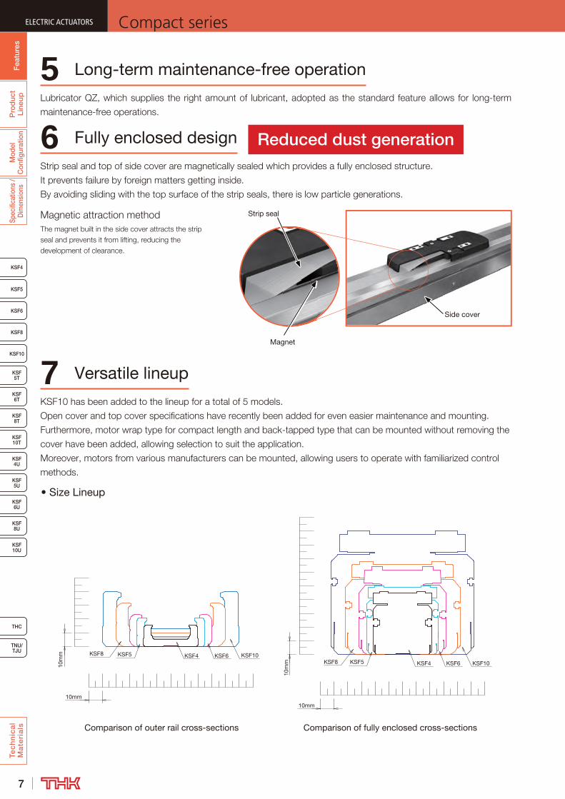
Comparison of outer rail cross-sections Comparison of fully enclosed cross-sections
5 Long-term maintenance-free operation
6 Fully enclosed design
7 Versatile lineup
Reduced dust generation
10m
m KSF4
10mm
10mm
10m
m
KSF5 KSF6KSF8 KSF10KSF10KSF8 KSF5 KSF4 KSF6
Magnet
Strip seal
Side cover

8
ELECTRIC ACTUATORSCompact series
Fea
ture
sP
rod
uct
Line
upM
odel
C
onfig
urat
ion
Spec
ifica
tions
/ D
imen
sion
sTe
ch
nic
al
Ma
teri
als
THC
TNU/TJU
KSF8
KSF4
KSF5
KSF6
KSF 10T
KSF10
KSF 5T
KSF 6T
KSF 8T
KSF 10U
KSF 4U
KSF 5U
KSF 6U
KSF 8U
8 Compact & Lightweight Sectional dimensions 67% down, weight 37% down
45.4
46
64
60
Compact & Lightweight
KSF4 VLAST60
86.4
68
Compact & Lightweight
110
160
KSF8 USW16T
0
0.5
1
1.5
2
2.5
3
3.5
4
4.5
5
0 100 200 300 400 500 600 700 800
Wei
ght
[kg]
Stroke [mm]
VLAST60 KSF4
Approx. 11% down
Approx. 37% down
0
5
10
15
20
25
30
35
40
45
Wei
ght
[kg]
Stroke [mm]
USW16T KSF8
0 100 200 300 400 500 600 700 800 900 1000 1100 1200 1300 1400 1500 1600

9
ELECTRIC ACTUATORS Compact seriesF
eatu
res
Pro
duc
t Li
neup
Mod
el
Con
figur
atio
nSp
ecifi
catio
ns /
Dim
ensi
ons
Tec
hn
ica
l M
ate
ria
ls
KSF8
KSF4
KSF5
KSF6
KSF 10T
KSF10
KSF 5T
KSF 6T
KSF 8T
KSF 10U
KSF 4U
KSF 5U
KSF 6U
KSF 8U
TNU/TJU
THC
Pro
duc
t Li
neup
Fea
ture
s
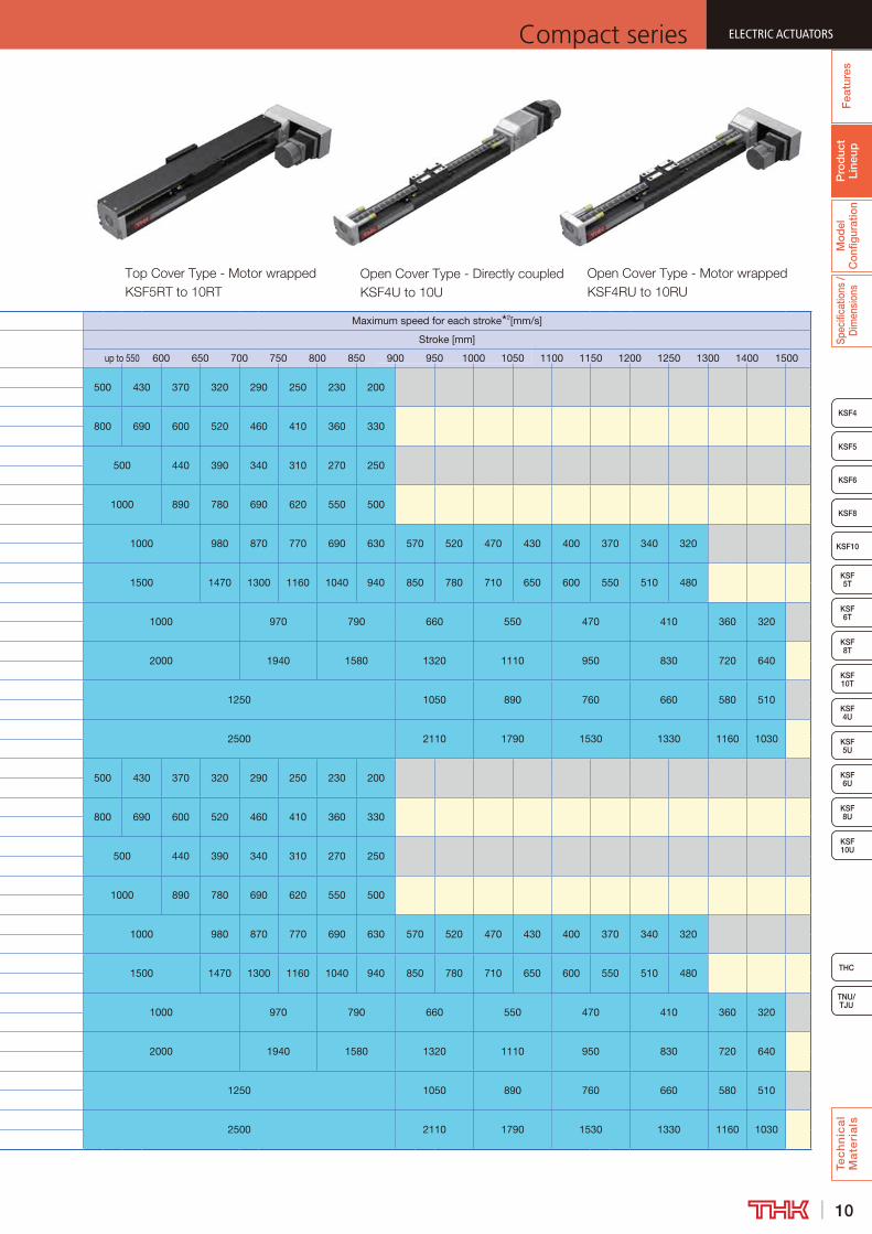
1 ( ) is the value for KSF10T, KSF10RT.2 The maximum speed is the value restricted by the motor rotational speed (at 3,000 min-1) or by the permissible rotational speed of the ball screw.-1
Product Lineup
ModelBall screw
lead [mm]
Stroke [mm]
Motor rated output
[W]
Acceleration and deceleration rate
[G]
Maximum load capacity 1[kg]
Horizontal/ Wall mount
Vertical mount
KSF4KSF4U
10
50 to 900 100
0.5 12 8
1.0 8 6
161.0 8 6
2.0 6 4
KSF5KSF5TKSF5U
10
50 to 900 100
0.5 20 13
1.0 15 8
201.0 7 6
2.0 5 3
KSF6KSF6TKSF6U
20
50 to 1300 200
1.0 22 10
2.0 5 3
301.0 14 6
2.0 6 4
KSF8KSF8TKSF8U
20
100 to 1500 400
1.0 43 20
2.0 6 3
401.0 16 8
2.0 7 5
KSF10KSF10TKSF10U
25
100 to 1500 750
1.0 60 (58) 25 (23)
1.5 26 13
501.0 17 (15) 9 (7)
1.5 8 5
KSF4RKSF4RU
10
50 to 900 100
0.5 12 8
1.0 8 6
161.0 8 6
2.0 6 4
KSF5RKSF5RTKSF5RU
10
50 to 900 100
0.5 20 11
1.0 15 8
201.0 7 5
2.0 4 2.5
KSF6RKSF6RTKSF6RU
20
50 to 1300 200
1.0 19 9
2.0 4 2.5
301.0 11 5
2.0 4 2.5
KSF8RKSF8RTKSF8RU
20
100 to 1500 400
1.0 41 20
2.0 6 3
401.0 16 8
2.0 7 5
KSF10RKSF10RTKSF10RU
25
100 to 1500 750
1.0 38 (36) 19 (17)
1.5 8 3
501.0 12 (10) 7 (5)
1.5 4 3
10
ELECTRIC ACTUATORSCompact series
Fea
ture
sP
rod
uct
Line
upM
odel
C
onfig
urat
ion
Spec
ifica
tions
/ D
imen
sion
sTe
ch
nic
al
Ma
teri
als
THC
TNU/TJU
KSF8
KSF4
KSF5
KSF6
KSF 10T
KSF10
KSF 5T
KSF 6T
KSF 8T
KSF 10U
KSF 4U
KSF 5U
KSF 6U
KSF 8U
Pro
duc
t Li
neup
Fea
ture
s
Maximum speed for each stroke 2[mm/s]
Stroke [mm]
up to 550 600 650 700 750 800 850 900 950 1000 1050 1100 1150 1200 1250 1300 1400 1500
500 430 370 320 290 250 230 200
800 690 600 520 460 410 360 330
500 440 390 340 310 270 250
1000 890 780 690 620 550 500
1000 980 870 770 690 630 570 520 470 430 400 370 340 320
1500 1470 1300 1160 1040 940 850 780 710 650 600 550 510 480
1000 970 790 660 550 470 410 360 320
2000 1940 1580 1320 1110 950 830 720 640
1250 1050 890 760 660 580 510
2500 2110 1790 1530 1330 1160 1030

11
ELECTRIC ACTUATORS Compact seriesF
eatu
res
Pro
duc
t Li
neup
Tec
hn
ica
l M
ate
ria
ls
KSF8
KSF5
KSF6
KSF 10T
KSF10
KSF 5T
KSF 6T
KSF 8T
KSF 10U
KSF 4U
KSF 5U
KSF 6U
KSF 8U
TNU/TJU
THC
Fea
ture
sM
odel
C
onfig
urat
ion
Pro
duc
t Li
neup
Spec
ifica
tions
/ D
imen
sion
s
KSF4
Model Configuration
KSF (THC Specifications)When combining with dedicated driver controller
ModelBall
screw lead
StrokeControl device
OptionMotor rated
output
Motor cable
orientationHome position
Power supply voltage
Cable length and type
KSF4 - 10 - 0050 - TH - GR-6 / M10 L S02 D1 H3(1) (2) (3) (4) (5) (6) (7) (8) (9) (10)
KSF4 10: 10 mm 0050: 50 mm TH: THC No symbol : None M10: 100 W R : Right D00 : Motor side D1: 100V No symbol: None
KSF5 16: 16 mm to MR : Motor right wrap M20: 200 W L : Left R00 : Reverse motor side D2: 200V F3 : Standard 3 mKSF6 20: 20 mm 1500: 1500 mm ML : Motor left wrap M40: 400 W U : Up S02 : Motor side (sensor right) F5 : Standard 5 mKSF8 25: 25 mm MD : Motor down wrap M75: 750W D : Down S03 : Reverse motor side (sensor right) FA : Standard 10 mKSF10 30: 30 mm T : Back tap M10B: 100W
with brake S20 : Motor side (sensor left) H3 : High flex 3 m
KSF4R 40: 40 mm GR : Change the cover color to gray S30 : Reverse motor side (sensor left) H5 : High flex 5 mKSF5R 50: 50 mm □ : Sensors M20B: 200W
with brake HA : High flex 10 m
KSF6RKSF8R M40B: 400W
with brakeKSF10R
M75B: 750W with brake
Ball screw leads you can select differ depending on models.KSF4: “10”, “16”KSF5: “10”, “20”KSF6: “20”, “30”KSF8: “20”, “40”KSF10: “25”, “50”
R represents motor wrap.
Separate order for the control device is required.
Indicates the type and length of attached cables.
Specify the optional symbol by wri t ing in the order of description from left adding “-”.Valid only when motor wrap
is selected in model (1).
Stroke and stroke pitch differ depending on models.KSF4: 50 to 900 mm(in 50mm pitch increments)KSF5: 50 to 900 mm(in 50mm pitch increments)KSF6: 50 to 1300 mm(in 50mm pitch increments)KSF8: 100 to 1500 mm(in 100mm pitch increments)KSF10: 100 to 1500 mm (in 100mm pitch increments)
(5) Option T: Back taps → P.127Sensors → P.128
GR: Change the cover color to gray → P.131
Pages for detailed description
+/
●: Position of the external home position sensor
D00
R00
S02
S03
S20
S30
D00 and R00 are mechanical home seeking.When motor wrap is selected, sensors cannot be mounted on the same side as the motor wrap direction.
If you select “MR” as an option, “R” cannot be selected.If you select “ML” as an option, “L” cannot be selected.If you select “MD” as an option, “U” cannot be selected.
Change the cover color to gray
You can change the color of a housing cover to gray.
Standard: red When GR is selected: gray
Motors you can select differ depending on models.KSF4: “M10”, “M10B”KSF5: “M10”, “M10B”KSF6: “M20”, “M20B”KSF8: “M40”, “M40B”KSF10: “M75”, “M75B”
/
(5) Motor wrap direction(7) Cable orientation (motor wrapped)
L (Left) R (Right)
D (Down)Motor cable orientation (Seen from side A)
U (Up)
A
Option symbol ML: Left-turn wrap
Option symbol MR: Right-turn wrap
Option symbol MD: Motor Down WrapSeen from side B
B
C
L: Left D :DownSeen from side C
R: Right
(8) Home position(7) Motor cable orientation (directly coupled)

12
ELECTRIC ACTUATORSCompact series
Fea
ture
sP
rod
uct
Line
upTe
ch
nic
al
Ma
teri
als
THC
TNU/TJU
KSF8
KSF5
KSF6
KSF 10T
KSF10
KSF 5T
KSF 6T
KSF 8T
KSF 10U
KSF 4U
KSF 5U
KSF 6U
KSF 8U
Fea
ture
sSp
ecifi
catio
ns /
Dim
ensi
ons
Pro
duc
t Li
neup
KSF4
Spec
ifica
tions
/ D
imen
sion
sM
odel
C
onfig
urat
ion
Model Configuration
KSF (type without motor)In the case of actuator main unit only, or when the motor specified by the customer is installed
/
(5) Intermediate flange → P.131(8) Options T: Back taps → P.127
Sensors → P.128GR: Change the cover color to gray → P.131
Pages for detailed description
When combining with dedicated driver controller (THC) KSF4-10-0150-TH-6/M10BRS02D2H5Main unit only (type without motor) KSF4R-16-0150-0-WQ-08K-MR-6Main unit only (when the motor specified by the customer is installed) KSF4-10-0150-1-AQ-GR
Model configuration coding
ModelBall
screw lead
StrokeWith/without
motor
Intermediate flange/ motor
mounting plate
Motor shaft diameter
Motor shaft fixing method
Option
KSF4R - 10 - 0050 - 0 - WQ - 08 K - ML-GR(1) (2) (3) (4) (5) (6) (7) (8)
KSF4 10: 10 mm 0050: 50 mm 0: Without motor A0 No symbol :Select when directly coupled No symbol :Select when directly coupled No symbol : NoneKSF5 20: 20 mm to 1: With motor AQ 08 : 8 mm D : D-cut MR : Motor right wrapKSF6 25: 25 mm 1500: 1500 mm AP 11 : 11 mm K : Key ML : Motor left wrapKSF8 30: 30 mm AR 14 : 14 mm M : Friction tightening MD : Motor down wrapKSF10 40: 40 mm AV 16 : 16 mm T : Back tapKSF4R 50: 50 mm AY 19 : 19 mm GR : Change the cover color to grayKSF5R AU □ : SensorsKSF6R AZKSF8R A5KSF10R A6
WQWPWVWYWZW5Stroke and stroke pitch differ
depending on models.
KSF4: 50 to 900 mm
(in 50mm pitch increments)
KSF5: 50 to 900 mm
(in 50mm pitch increments)
KSF6: 50 to 1300 mm
(in 50mm pitch increments)
KSF8: 100 to 1500 mm
(in 100mm pitch increments)
KSF10: 100 to 1500 mm
(in 100mm pitch increments)
Specify the optional symbol by writing in the order of description from left adding “-”.Valid only when
motor wrap is selected in model (1).
Ball screw leads you can select differ depending on models.KSF4: “10”, “16”KSF5: “10”, “20”KSF6: “20”, “30”KSF8: “20”, “40”KSF10: “25”, “50”
Motor shaft fixing methods you can select differ depending on models.KSF4R: “D”, “K”KSF5R: “D”, “K”KSF6R: “D”, “K”, “M”KSF8R: “M”KSF10: “M”
R represents motor wrap.
When selecting “0”, a coupling is not provided.When selecting “1”, the motor you specify will be installed.
Specify the motor cable orientation separately.
Change the cover color to gray
You can change the color of a housing cover to gray.
Standard: red When GR is selected: gray
/
13
ELECTRIC ACTUATORS Compact seriesF
eatu
res
Pro
duc
t Li
neup
Tec
hn
ica
l M
ate
ria
ls
KSF8
KSF5
KSF6
KSF 10T
KSF10
KSF 5T
KSF 6T
KSF 8T
KSF 10U
KSF 4U
KSF 5U
KSF 6U
KSF 8U
TNU/TJU
THC
Fea
ture
sM
odel
C
onfig
urat
ion
Pro
duc
t Li
neup
Spec
ifica
tions
/ D
imen
sion
s
KSF4
ModelBall
screw lead
StrokeControl device
OptionMotor rated
outputMotor cable
orientationHome position
Power supply voltage
Cable length and
type
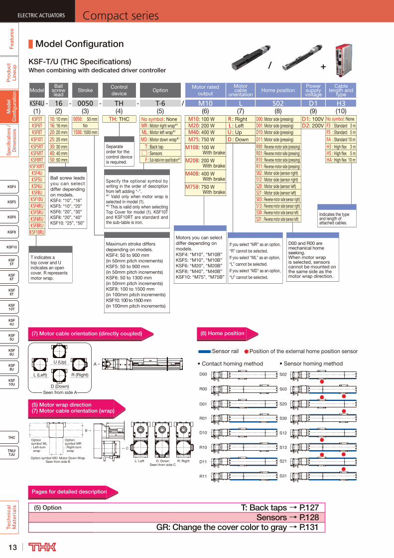
KSF4U - 16 - 0050 - TH - T-6 / M10 L S02 D1 H3(1) (2) (3) (4) (5) (6) (7) (8) (9) (10)
KSF5T 10: 10 mm 0050: 50 mm TH: THC No symbol : None M10: 100 W R : Right D00 : Motor side (pressing) D1: 100V No symbol: NoneKSF6T 16: 16 mm to MR : Motor right wrap 1 M20: 200 W L : Left D01 : Motor side (pressing) D2: 200V F3 : Standard 3 mKSF8T 20: 20 mm 1500: 1500 mm ML : Motor left wrap 1 M40: 400 W U : Up D10 : Motor side (pressing) F5 : Standard 5 mKSF10T 25: 25 mm MD : Motor down wrap 1 M75: 750 W D : Down D11 : Motor side (pressing) FA : Standard 10 mKSF5RT 30: 30 mm T : Back tap M10B: 100 W
With brake R00 : Reverse motor side (pressing) H3 : High flex 3 m
KSF6RT 40: 40 mm □ : Sensors R01 : Reverse motor side (pressing) H5 : High flex 5 mKSF8RT 50: 50 mm F : Sub-table iron specification 2 M20B: 200 W
With brake R10 : Reverse motor side (pressing) HA : High flex 10 m
KSF10RT R11 : Reverse motor side (pressing)KSF4U M40B: 400 W
With brake S02 : Motor side (sensor right)
KSF5U S12 : Motor side (sensor right)KSF6U M75B: 750 W
With brake S20 : Motor side (sensor left)
KSF8U S21 : Motor side (sensor left)KSF10U S03 : Reverse motor side (sensor right)KSF4RU S13 : Reverse motor side (sensor right)KSF5RU S30 : Reverse motor side (sensor left)KSF6RU S31 : Reverse motor side (sensor left)KSF8RUKSF10RU
Model Configuration
KSF-T/U (THC Specifications)When combining with dedicated driver controller
Ball screw leads you can select differ depending on models.KSF4: “10”, “16”KSF5: “10”, “20”KSF6: “20”, “30”KSF8: “20”, “40”KSF10: “25”, “50”
Separate order for the control device is required.
Indicates the type and length of attached cables.
Specify the optional symbol by writing in the order of description from left adding “-”.
1 Valid only when motor wrap is selected in model (1).
2 This is valid only when selecting Top Cover for model (1). KSF10T and KSF10RT are standard and the sub-table is iron.
Maximum stroke differs depending on models.KSF4: 50 to 900 mm(in 50mm pitch increments)KSF5: 50 to 900 mm(in 50mm pitch increments)KSF6: 50 to 1300 mm(in 50mm pitch increments)KSF8: 100 to 1500 mm(in 100mm pitch increments)KSF10: 100 to 1500 mm (in 100mm pitch increments)
Pages for detailed description
D00 and R00 are mechanical home seeking.When motor wrap is selected, sensors cannot be mounted on the same side as the motor wrap direction.
If you select “MR” as an option, “R” cannot be selected.If you select “ML” as an option, “L” cannot be selected.If you select “MD” as an option, “U” cannot be selected.
Motors you can select differ depending on models.KSF4: “M10”, “M10B”KSF5: “M10”, “M10B”KSF6: “M20”, “M20B”KSF8: “M40”, “M40B”KSF10: “M75”, “M75B”
(7) Motor cable orientation (directly coupled)
(5) Motor wrap direction(7) Motor cable orientation (wrap)
T indicates a top cover and U indicates an open cover. R represents motor wrap.
(8) Home position
:Position of the external home position sensor:Sensor rail
D00 S02
D01 S20
D10 S12
D11 S21
R00 S03
R01 S30
R10 S13
R11 S31
A
L (Left) R (Right)
D (Down)Seen from side A
U (Up)
L: Left D :DownSeen from side C
R: Right
Option symbol ML: Left-turn wrap
Option symbol MR: Right-turn wrap
Option symbol MD: Motor Down WrapSeen from side B
B
C
(5) Option T: Back taps → P.127Sensors → P.128
GR: Change the cover color to gray → P.131
/ +
14
ELECTRIC ACTUATORSCompact series
Fea
ture
sP
rod
uct
Line
upTe
ch
nic
al
Ma
teri
als
THC
TNU/TJU
KSF8
KSF5
KSF6
KSF 10T
KSF10
KSF 5T
KSF 6T
KSF 8T
KSF 10U
KSF 4U
KSF 5U
KSF 6U
KSF 8U
Fea
ture
sSp
ecifi
catio
ns /
Dim
ensi
ons
Pro
duc
t Li
neup
KSF4
Spec
ifica
tions
/ D
imen
sion
sM
odel
C
onfig
urat
ionModel
Ball screw lead
StrokeWith/without
motor
Intermediate flange/
motor mounting plate
Motor shaft diameter
Motor shaft fixing method
Option
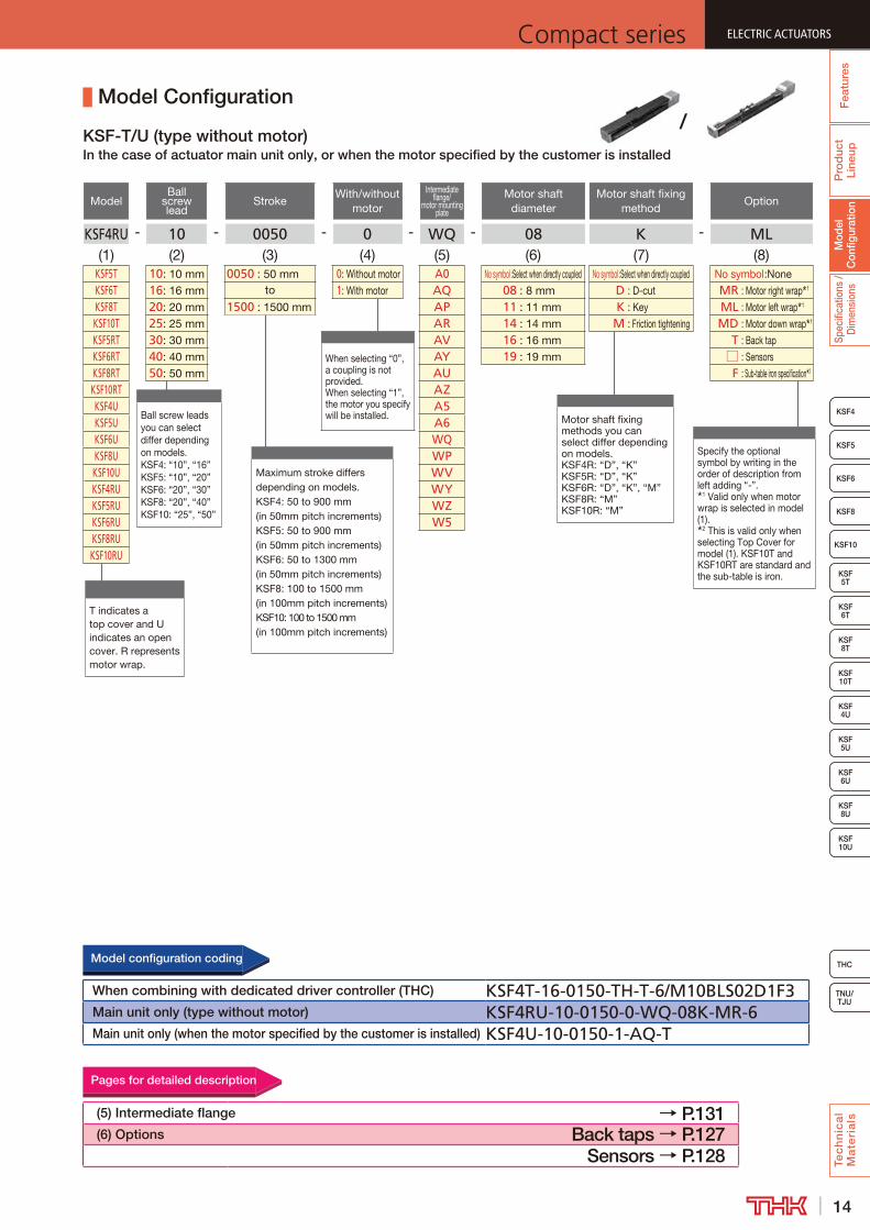
KSF4RU - 10 - 0050 - 0 - WQ - 08 K - ML(1) (2) (3) (4) (5) (6) (7) (8)
KSF5T 10: 10 mm 0050 : 50 mm 0: Without motor A0 No symbol :Select when directly coupled No symbol :Select when directly coupled No symbol :NoneKSF6T 16: 16 mm to 1: With motor AQ 08 : 8 mm D : D-cut MR : Motor right wrap 1
KSF8T 20: 20 mm 1500 : 1500 mm AP 11 : 11 mm K : Key ML : Motor left wrap 1
KSF10T 25: 25 mm AR 14 : 14 mm M : Friction tightening MD : Motor down wrap 1
KSF5RT 30: 30 mm AV 16 : 16 mm T : Back tapKSF6RT 40: 40 mm AY 19 : 19 mm □ : SensorsKSF8RT 50: 50 mm AU F : Sub-table iron specification 2
KSF10RT AZKSF4U A5KSF5U A6KSF6U WQKSF8U WPKSF10U WVKSF4RU WYKSF5RU WZKSF6RU W5KSF8RUKSF10RU
Maximum stroke differs depending on models.KSF4: 50 to 900 mm(in 50mm pitch increments)KSF5: 50 to 900 mm(in 50mm pitch increments)KSF6: 50 to 1300 mm(in 50mm pitch increments)KSF8: 100 to 1500 mm(in 100mm pitch increments)KSF10: 100 to 1500 mm (in 100mm pitch increments)
Model Configuration
KSF-T/U (type without motor)In the case of actuator main unit only, or when the motor specified by the customer is installed
Ball screw leads you can select differ depending on models.KSF4: “10”, “16”KSF5: “10”, “20”KSF6: “20”, “30”KSF8: “20”, “40”KSF10: “25”, “50”
T indicates a top cover and U indicates an open cover. R represents motor wrap.
When selecting “0”, a coupling is not provided.When selecting “1”, the motor you specify will be installed.
Specify the optional symbol by writing in the order of description from left adding “-”.
1 Valid only when motor wrap is selected in model (1).
2 This is valid only when selecting Top Cover for model (1). KSF10T and KSF10RT are standard and the sub-table is iron.
Motor shaft fixing methods you can select differ depending on models.KSF4R: “D”, “K”KSF5R: “D”, “K”KSF6R: “D”, “K”, “M”KSF8R: “M”KSF10R: “M”
(5) Intermediate flange → P.131(6) Options Back taps → P.127
Sensors → P.128
Pages for detailed description
When combining with dedicated driver controller (THC) KSF4T-16-0150-TH-T-6/M10BLS02D1F3Main unit only (type without motor) KSF4RU-10-0150-0-WQ-08K-MR-6Main unit only (when the motor specified by the customer is installed) KSF4U-10-0150-1-AQ-T
Model configuration coding
/
15
ELECTRIC ACTUATORS Compact seriesF
eatu
res
Pro
duc
t Li
neup
Tec
hn
ica
l M
ate
ria
ls
KSF8
KSF5
KSF6
KSF 10T
KSF10
KSF 5T
KSF 6T
KSF 8T
KSF 10U
KSF 4U
KSF 5U
KSF 6U
KSF 8U
TNU/TJU
THC
Fea
ture
s
KSF4
Spec
ifica
tions
/ D
imen
sion
sM
odel
C
onfig
urat
ion
Pro
duc
t Li
neup
+
Model Configuration
ModelBall
screw lead
StrokeControl device
Option Motor rated outputMotor cable
orientationHome position
Power supply voltage
Cable type and length
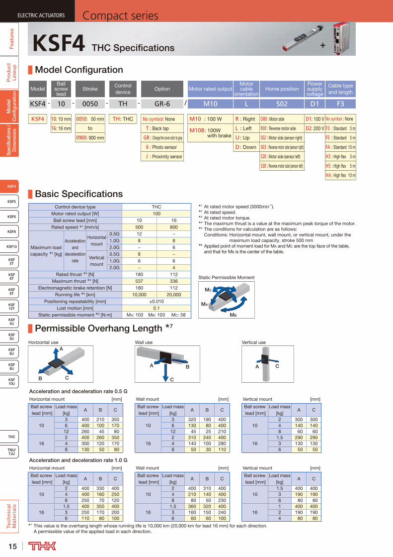
KSF4 - 10 - 0050 - TH - GR-6 / M10 L S02 D1 F3
KSF4 10: 10 mm 0050: 50 mm TH: THC No symbol: None M10 : 100 W R : Right D00 : Motor side D1: 100 V No symbol : None
16: 16 mm to T : Back tap M10B: 100W with brake
L : Left R00 : Reverse motor side D2: 200 V F3 : Standard 3 m
0900: 900 mm GR : Change the cover color to gray U : Up S02 : Motor side (sensor right) F5 : Standard 5 m
6 : Photo sensor D : Down S03 : Reverse motor side (sensor right) FA : Standard 10 m
J : Proximity sensor S20 : Motor side (sensor left) H3 : High flex 3 m
S30 : Reverse motor side (sensor left) H5 : High flex 5 m
HA : High flex 10 m
Basic SpecificationsControl device type THC
Motor rated output [W] 100Ball screw lead [mm] 10 16
Rated speed 1 [mm/s] 500 800
Maximum load capacity 2 [kg]
Acceleration and
deceleration rate
Horizontal mount
0.5G 12 −1.0G 8 82.0G − 6
Vertical mount
0.5G 8 −1.0G 6 62.0G − 4
Rated thrust 3 [N] 180 112Maximum thrust 4 [N] 537 336
Electromagnetic brake retention [N] 180 112Running life 5 [km] 10,000 20,000
Positioning repeatability [mm] ±0.010Lost motion [mm] 0.1
Static permissible moment 6 [N·m] MA: 103 MB: 103 MC: 58
Permissible Overhang Length 7
Horizontal use Wall use Vertical use
CB
A
A B
C
A C
Acceleration and deceleration rate 0.5 GHorizontal mount [mm] Wall mount [mm] Vertical mount [mm]
Ball screw lead [mm]
Load mass [kg]
A B CBall screw lead [mm]
Load mass [kg]
A B CBall screw lead [mm]
Load mass [kg]
A C
103 400 210 350
103 320 190 400
102 300 300
6 400 100 170 6 130 80 400 4 140 14012 260 45 80 12 45 25 210 8 60 60
162 400 260 350
162 310 240 400
161.5 290 290
4 300 120 170 4 140 100 280 3 130 1308 130 50 80 8 50 30 110 6 50 50
Acceleration and deceleration rate 1.0 GHorizontal mount [mm] Wall mount [mm] Vertical mount [mm]
Ball screw lead [mm]
Load mass [kg]
A B CBall screw lead [mm]
Load mass [kg]
A B CBall screw lead [mm]
Load mass [kg]
A C
102 400 330 400
102 400 310 400
101.5 400 400
4 400 160 250 4 210 140 400 3 190 1908 250 70 120 8 80 50 230 6 80 80
161.5 400 350 400
161.5 360 320 400
161 400 400
3 250 170 200 3 160 150 240 2 190 1906 110 80 100 6 60 60 100 4 80 80
7 This value is the overhang length whose running life is 10,000 km (20,000 km for lead 16 mm) for each direction. A permissible value of the applied load in each direction.
KSF4 THC Specifications
MB
MA
MC
Static Permissible Moment
+
1 At rated motor speed (3000min-1).2 At rated speed.3 At rated motor torque.4 The maximum thrust is a value at the maximum peak torque of the motor.5 The conditions for calculation are as follows:
Conditions: Horizontal mount, wall mount, or vertical mount, under the maximum load capacity, stroke 500 mm
6 Applied point of moment load for MA and MC are the top face of the table, and that for MB is the center of the table.
16
ELECTRIC ACTUATORSCompact series
Fea
ture
sP
rod
uct
Line
upTe
ch
nic
al
Ma
teri
als
THC
TNU/TJU
KSF8
KSF5
KSF6
KSF 10T
KSF10
KSF 5T
KSF 6T
KSF 8T
KSF 10U
KSF 4U
KSF 5U
KSF 6U
KSF 8U
Fea
ture
sSp
ecifi
catio
ns /
Dim
ensi
ons
KSF4
Mod
el
Con
figur
atio
nP
rod
uct
Line
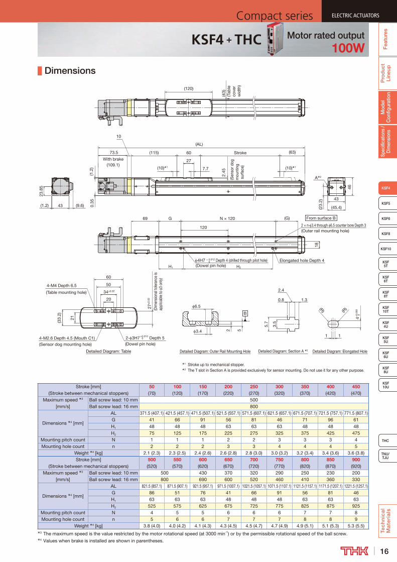
up Dimensions
Detailed Diagram: Outer Rail Mounting HoleDetailed Diagram: Table Detailed Diagram: Section A 2
1 Stroke up to mechanical stopper.2 The T slot in Section A is provided exclusively for sensor mounting. Do not use it for any other purpose.
(G)
4-M4 Depth 6.5
(Table mounting hole)
(9.6)
69
A 2
27
2.4
5
18
(120)
46
43
34±0.02
20
50
N × 120
60
120
G
(63)Stroke 73.5
With brake(109.1)
10
(AL)
(10) 1
(115)
(10) 1
27±
0.02
(Dim
ensio
nal t
oler
ance
is
appl
icab
le to
3
only)
43
23.8
5
7.7
4-M2.6 Depth 4.5 (Mouth C1)(Sensor dog mounting hole)
2- 3H7+0.010 0 Depth 5(Dowel pin hole)
(1.2
)0.
35
(43)
(Tab
le
cove
r w
idth
)
(23.
2)
21
(33.
2)
(Sen
sor d
ogm
ount
ing
sur
face
)
(1.2)
B
52
6.5
3.4
Detailed Diagram: Elongated Hole
4H7 + 0.012 0 Depth 4 (drilled through pilot hole)
H1 H2
Elongated hole Depth 4(Dowel pin hole)
(R)
1 1
4+0.
030
0
(R)
From surface B
2 × n- 3.4 through 6.5 counter bore Depth 3(Outer rail mounting hole)
(45.4)
60
0.8
5.7
3.5
2.4
1.3
Stroke [mm] (Stroke between mechanical stoppers)
50 (70)
100 (120)
150 (170)
200 (220)
250 (270)
300 (320)
350 (370)
400 (420)
450 (470)
Maximum speed 3 [mm/s]
Ball screw lead: 10 mm 500Ball screw lead: 16 mm 800
Dimensions 4 [mm]
AL 371.5 (407.1) 421.5 (457.1) 471.5 (507.1) 521.5 (557.1) 571.5 (607.1) 621.5 (657.1) 671.5 (707.1) 721.5 (757.1) 771.5 (807.1)G 41 66 91 56 81 46 71 96 61H1 48 48 48 63 63 63 48 48 48H2 75 125 175 225 275 325 375 425 475
Mounting pitch count N 1 1 1 2 2 3 3 3 4Mounting hole count n 2 2 2 3 3 4 4 4 5
Weight 4 [kg] 2.1 (2.3) 2.3 (2.5) 2.4 (2.6) 2.6 (2.8) 2.8 (3.0) 3.0 (3.2) 3.2 (3.4) 3.4 (3.6) 3.6 (3.8)Stroke [mm]
(Stroke between mechanical stoppers)500 (520)
550 (570)
600 (620)
650 (670)
700 (720)
750 (770)
800 (820)
850 (870)
900 (920)
Maximum speed 3 [mm/s]
Ball screw lead: 10 mm 500 430 370 320 290 250 230 200Ball screw lead: 16 mm 800 690 600 520 460 410 360 330
Dimensions 4 [mm]
AL 821.5 (857.1) 871.5 (907.1) 921.5 (957.1) 971.5 (1007.1) 1021.5 (1057.1) 1071.5 (1107.1) 1121.5 (1157.1) 1171.5 (1207.1) 1221.5 (1257.1)G 86 51 76 41 66 91 56 81 46H1 63 63 63 48 48 48 63 63 63H2 525 575 625 675 725 775 825 875 925
Mounting pitch count N 4 5 5 6 6 6 7 7 8Mounting hole count n 5 6 6 7 7 7 8 8 9
Weight 4 [kg] 3.8 (4.0) 4.0 (4.2) 4.1 (4.3) 4.3 (4.5) 4.5 (4.7) 4.7 (4.9) 4.9 (5.1) 5.1 (5.3) 5.3 (5.5)3 The maximum speed is the value restricted by the motor rotational speed (at 3000 min-1) or by the permissible rotational speed of the ball screw.4 Values when brake is installed are shown in parentheses.
KSF4 + THC Motor rated output100W
17
ELECTRIC ACTUATORS Compact seriesF
eatu
res
Pro
duc
t Li
neup
Tec
hn
ica
l M
ate
ria
ls
KSF8
KSF5
KSF6
KSF 10T
KSF10
KSF 5T
KSF 6T
KSF 8T
KSF 10U
KSF 4U
KSF 5U
KSF 6U
KSF 8U
TNU/TJU
THC
Fea
ture
s
KSF4
Spec
ifica
tions
/ D
imen
sion
sM
odel
C
onfig
urat
ion
Pro
duc
t Li
neup
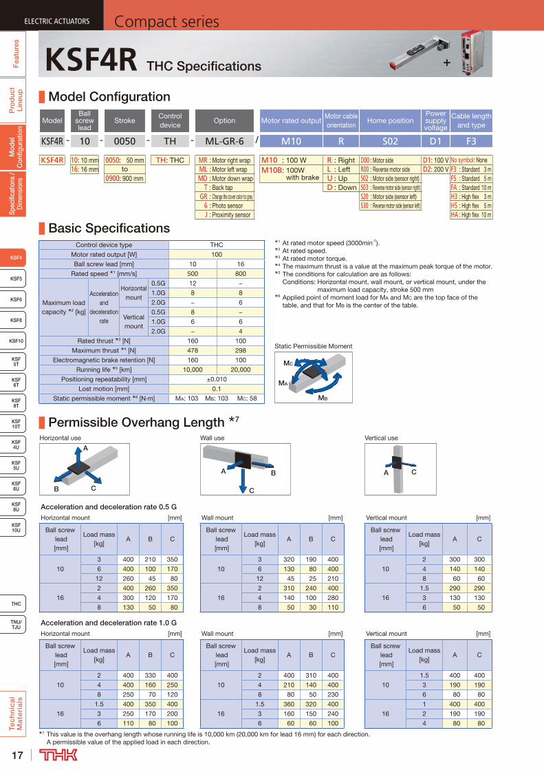
+KSF4R THC Specifications
Model Configuration
Model -Ball
screw lead
- Stroke -Control device
- Option / Motor rated outputMotor cable orientation
Home positionPower supply voltage
Cable length and type
KSF4R - 10 - 0050 - TH - ML-GR-6 / M10 R S02 D1 F3
KSF4R 10: 10 mm 0050: 50 mm TH: THC MR : Motor right wrap M10 : 100 W R : Right D00 : Motor side D1: 100 V No symbol: None16: 16 mm to ML : Motor left wrap M10B: 100W
with brakeL : Left R00 : Reverse motor side D2: 200 V F3 : Standard 3 m
0900: 900 mm MD : Motor down wrap U : Up S02 : Motor side (sensor right) F5 : Standard 5 m T : Back tap D : Down S03 : Reverse motor side (sensor right) FA : Standard 10 m GR : Change the cover color to gray S20 : Motor side (sensor left) H3 : High flex 3 m 6 : Photo sensor S30 : Reverse motor side (sensor left) H5 : High flex 5 m J : Proximity sensor HA : High flex 10 m
Basic SpecificationsControl device type THC
Motor rated output [W] 100
Ball screw lead [mm] 10 16
Rated speed 1 [mm/s] 500 800
Maximum load capacity 2 [kg]
Acceleration and
deceleration rate
Horizontal mount
0.5G 12 −
1.0G 8 8
2.0G − 6
Vertical mount
0.5G 8 −
1.0G 6 6
2.0G − 4
Rated thrust 3 [N] 160 100
Maximum thrust 4 [N] 478 298
Electromagnetic brake retention [N] 160 100
Running life 5 [km] 10,000 20,000
Positioning repeatability [mm] ±0.010
Lost motion [mm] 0.1
Static permissible moment 6 [N·m] MA: 103 MB: 103 MC: 58
Permissible Overhang Length 7
Horizontal use Wall use Vertical use
CB
A
A B
C
A C
Acceleration and deceleration rate 0.5 GHorizontal mount [mm] Wall mount [mm] Vertical mount [mm]
Ball screw lead [mm]
Load mass [kg]
A B CBall screw
lead [mm]
Load mass [kg]
A B CBall screw
lead [mm]
Load mass [kg]
A C
10
3 400 210 350
10
3 320 190 400
10
2 300 300
6 400 100 170 6 130 80 400 4 140 140
12 260 45 80 12 45 25 210 8 60 60
16
2 400 260 350
16
2 310 240 400
16
1.5 290 290
4 300 120 170 4 140 100 280 3 130 130
8 130 50 80 8 50 30 110 6 50 50
Acceleration and deceleration rate 1.0 GHorizontal mount [mm] Wall mount [mm] Vertical mount [mm]
Ball screw lead [mm]
Load mass [kg]
A B CBall screw
lead [mm]
Load mass [kg]
A B CBall screw
lead [mm]
Load mass [kg]
A C
10
2 400 330 400
10
2 400 310 400
10
1.5 400 400
4 400 160 250 4 210 140 400 3 190 190
8 250 70 120 8 80 50 230 6 80 80
16
1.5 400 350 400
16
1.5 360 320 400
16
1 400 400
3 250 170 200 3 160 150 240 2 190 190
6 110 80 100 6 60 60 100 4 80 807 This value is the overhang length whose running life is 10,000 km (20,000 km for lead 16 mm) for each direction.
A permissible value of the applied load in each direction.
1 At rated motor speed (3000min-1).2 At rated speed.3 At rated motor torque.4 The maximum thrust is a value at the maximum peak torque of the motor.5 The conditions for calculation are as follows:
Conditions: Horizontal mount, wall mount, or vertical mount, under the maximum load capacity, stroke 500 mm
6 Applied point of moment load for MA and MC are the top face of the table, and that for MB is the center of the table.
MB
MA
MC
Static Permissible Moment
18
ELECTRIC ACTUATORSCompact series
Fea
ture
sP
rod
uct
Line
upTe
ch
nic
al
Ma
teri
als
THC
TNU/TJU
KSF8
KSF5
KSF6
KSF 10T
KSF10
KSF 5T
KSF 6T
KSF 8T
KSF 10U
KSF 4U
KSF 5U
KSF 6U
KSF 8U
Fea
ture
sSp
ecifi
catio
ns /
Dim
ensi
ons
KSF4
Mod
el
Con
figur
atio
nP
rod
uct
Line
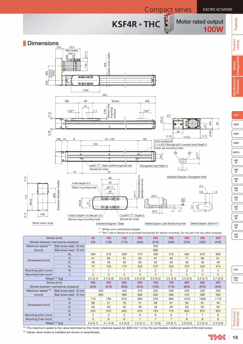
up Dimensions
1 Stroke up to mechanical stopper.2 The T slot in Section A is provided exclusively for sensor mounting. Do not use it for any other purpose.
From surface B2 × n- 3.4 through 6.5 counter bore Depth 3(Outer rail mounting hole)
Elongated hole Depth 44H7 +0.0120 Depth 4 (drilled through pilot hole)
(G)
0.35
(1.2
)
18
7.7(10) 1
Stroke60
27
(10) 1
(AL)
(96)2.
45(S
enso
r d
og
mou
ntin
g su
rfac
e)
N × 120
(43)
(Tab
le c
over
wid
th)
24(26)
Motor down wrap
(20)
(120)
(31)
(11.
1)□
40
H2H1
G
120
(60)
(Dis
tanc
e b
etw
een
shaf
ts)
(63)
73.5With brake
(109.1)(6
0)
(Dis
tanc
e b
etw
een
shaf
ts)
112
(68.
2)
(1.7
)
(42)
(1.7
)
(42)
113.5
(23.
2)
43
46
21
A 2
(1.2) (1.7) (2.8
5)
Detailed Diagram: Elongated Hole
(R)
1 1
4+0.
030
0
(R)
Detailed Diagram: Outer Rail Mounting Hole Detailed Diagram: Section A 2
B
52
6.5
3.4
0.85.
7
3.5
2.4
1.3
Detailed Diagram: Table
4-M4 Depth 6.5
(Table mounting hole) 34±0.02
20
50
27±
0.02
(Dim
ensio
nal t
oler
ance
is
appl
icab
le to
3
only)
4-M2.6 Depth 4.5 (Mouth C1)(Sensor dog mounting hole)
2- 3H7 +0.010 0 Depth 5(Dowel pin hole)
21
(33.
2)
60
(Dowel pin hole)
Stroke [mm] (Stroke between mechanical stoppers)
50 (70)
100 (120)
150 (170)
200 (220)
250 (270)
300 (320)
350 (370)
400 (420)
450 (470)
Maximum speed 3 [mm/s]
Ball screw lead: 10 mm 500Ball screw lead: 16 mm 800
Dimensions [mm]
AL 269 319 369 419 469 519 569 619 669G 41 66 91 56 81 46 71 96 61H1 48 48 48 63 63 63 48 48 48H2 75 125 175 225 275 325 375 425 475
Mounting pitch count N 1 1 1 2 2 3 3 3 4Mounting hole count n 2 2 2 3 3 4 4 4 5
Weight 4 [kg] 2.2 (2.4) 2.4 (2.6) 2.6 (2.8) 2.8 (3.0) 3.0 (3.2) 3.2 (3.4) 3.3 (3.5) 3.5 (3.7) 3.7 (3.9)Stroke [mm]
(Stroke between mechanical stoppers)500 (520)
550 (570)
600 (620)
650 (670)
700 (720)
750 (770)
800 (820)
850 (870)
900 (920)
Maximum speed 3 [mm/s]
Ball screw lead: 10 mm 500 430 370 320 290 250 230 200Ball screw lead: 16 mm 800 690 600 520 460 410 360 330
Dimensions [mm]
AL 719 769 819 869 919 969 1019 1069 1119G 86 51 76 41 66 91 56 81 46H1 63 63 63 48 48 48 63 63 63H2 525 575 625 675 725 775 825 875 925
Mounting pitch count N 4 5 5 6 6 6 7 7 8Mounting hole count n 5 6 6 7 7 7 8 8 9
Weight 4 [kg] 3.9 (4.1) 4.1 (4.3) 4.3 (4.5) 4.5 (4.7) 4.7 (4.9) 4.9 (5.1) 5.0 (5.2) 5.2 (5.4) 5.4 (5.6)3 The maximum speed is the value restricted by the motor rotational speed (at 3000 min-1) or by the permissible rotational speed of the ball screw.4 Values when brake is installed are shown in parentheses.
Motor rated output100W
KSF4R + THC
19
ELECTRIC ACTUATORS Compact seriesP
rod
uct
Line
upTe
ch
nic
al
Ma
teri
als
KSF8
KSF4
KSF 10T
KSF10
KSF 5T
KSF 6T
KSF 8T
KSF 10U
KSF 4U
KSF 5U
KSF 6U
KSF 8U
TNU/TJU
THC
KSF5
KSF6
Spec
ifica
tions
/ D
imen
sion
sM
odel
C
onfig
urat
ion
Fea
ture
sELECTRIC ACTUATORS Compact series
+
Model Configuration
Model -Ball
screw lead
- Stroke -Control device
- Option / Motor rated outputMotor cable
orientationHome position
Power supply voltage
Cable length and type
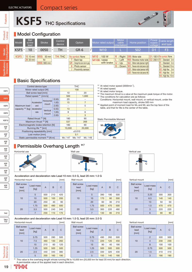
KSF5 - 10 - 0050 - TH - GR-6 / M10 L S02 D1 F3
KSF5 10: 10 mm 0050: 50 mm TH: THC No symbol: None M10 : 100 W R : Right D00 : Motor side D1: 100 V No symbol: None20: 20 mm to T : Back tap M10B: 100W
with brakeL : Left R00 : Reverse motor side D2: 200 V F3 : Standard 3 m
0900: 900 mm GR : Change the cover color to gray U : Up S02 : Motor side (sensor right) F5 : Standard 5 m 6 : Photo sensor D : Down S03 : Reverse motor side (sensor right) FA : Standard 10 m J : Proximity sensor S20 : Motor side (sensor left) H3 : High flex 3 m
S30 : Reverse motor side (sensor left) H5 : High flex 5 mHA : High flex 10 m
Basic SpecificationsControl device type THC
Motor rated output [W] 100Ball screw lead [mm] 10 20
Rated speed 1 [mm/s] 500 1,000
Maximum load capacity 2 [kg]
Acceleration and
deceleration rate
Horizontal mount
0.5G 20 −1.0G 15 72.0G − 5
Vertical mount
0.5G 13 −1.0G 8 62.0G − 3
Rated thrust 3 [N] 180 90Maximum thrust 4 [N] 537 269
Electromagnetic brake retention [N] 180 90Running life 5 [km] 10,000 20,000
Positioning repeatability [mm] ±0.010Lost motion [mm] 0.1
Static permissible moment 6 [N·m] MA: 147 MB: 147 MC: 149
Permissible Overhang Length 7
Horizontal use Wall use Vertical use
CB
A
A B
C
A C
Acceleration and deceleration rate Lead 10 mm: 0.5 G, lead 20 mm: 1.0 GHorizontal mount [mm] Wall mount [mm] Vertical mount [mm]
Ball screw lead [mm]
Load mass [kg]
A B CBall screw
lead [mm]
Load mass [kg]
A B CBall screw
lead [mm]
Load mass [kg]
A C
10
5 500 210 420
10
5 390 190 500
10
3.25 300 300
10 500 100 200 10 170 80 500 6.5 140 140
20 250 40 90 20 60 30 210 13 50 50
20
1.75 500 490 500
20
1.75 500 470 500
20
1.5 470 470
3.5 500 240 340 3.5 300 220 480 3 220 220
7 230 110 170 7 130 90 210 6 90 90
Acceleration and deceleration rate Lead 10 mm: 1.0 G, lead 20 mm: 2.0 GHorizontal mount [mm] Wall mount [mm] Vertical mount [mm]
Ball screw lead [mm]
Load mass [kg]
A B CBall screw
lead [mm]
Load mass [kg]
A B CBall screw
lead [mm]
Load mass [kg]
A C
10
3.75 500 280 500
10
3.75 490 260 500
10
2 500 500
7.5 460 130 260 7.5 220 120 450 4 230 230
15 210 60 120 15 90 40 190 8 100 100
20
1.25 500 500 500
20
1.25 500 500 500
20
0.75 500 500
2.5 440 340 380 2.5 330 320 430 1.5 410 410
5 200 160 190 5 150 140 190 3 190 1907 This value is the overhang length whose running life is 10,000 km (20,000 km for lead 20 mm) for each direction.
A permissible value of the applied load in each direction.
1 At rated motor speed (3000min-1).2 At rated speed.3 At rated motor torque.4 The maximum thrust is a value at the maximum peak torque of the motor.5 The conditions for calculation are as follows:
Conditions: Horizontal mount, wall mount, or vertical mount, under the maximum load capacity, stroke 500 mm
6 Applied point of moment load for MA and MC are the top face of the table, and that for MB is the center of the table.
MB
MA
MC
Static Permissible Moment
+KSF5 THC Specifications
20
ELECTRIC ACTUATORSCompact series
Pro
duc
t Li
neup
Tec
hn
ica
l M
ate
ria
ls
THC
TNU/TJU
KSF8
KSF4
KSF 10T
KSF10
KSF 5T
KSF 6T
KSF 8T
KSF 10U
KSF 4U
KSF 5U
KSF 6U
KSF 8U
KSF5
KSF6
Spec
ifica
tions
/ D
imen
sion
sM
odel
C
onfig
urat
ion
Fea
ture
s
ELECTRIC ACTUATORSCompact series
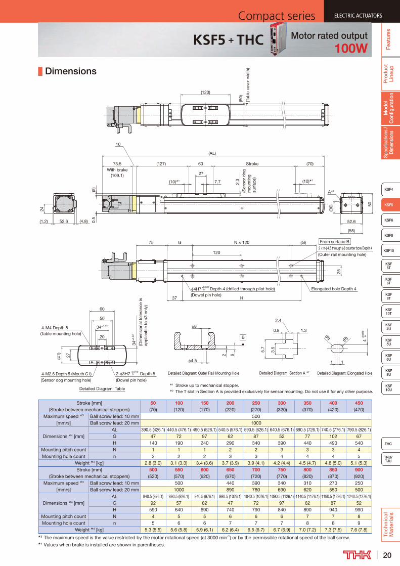
Dimensions
1 Stroke up to mechanical stopper.2 The T slot in Section A is provided exclusively for sensor mounting. Do not use it for any other purpose.
Detailed Diagram: Outer Rail Mounting Hole
Detailed Diagram: Table
Detailed Diagram: Elongated HoleDetailed Diagram: Section A 2
1.30.8
2.4
3.5
5.7
A 2
(41)
B
8
2
4.5
6
Stroke
2- 3H7 Depth 5
(Dowel pin hole)
20
(127) 60
27
7.7
(50)
(Tab
le c
over
wid
th)
2.3
(Sen
sor
dog
m
ount
ing
surf
ace)(10) 1
(55)
27
50
52.6
(10) 1
34±
0.02
(Dim
ensi
onal
tol
eran
ce is
ap
plic
able
to
3 on
ly)
4-M2.6 Depth 5 (Mouth C1)
(Sensor dog mounting hole)
(30)
4-M4 Depth 8(Table mounting hole)
50
(120)
34±0.02
60
(70)
(5)
0.5
73.5With brake
(109.1)
10
(AL)
52.6 (4.8)(1.2)
From surface B(G)N × 120
120
37 H
75 G
Elongated hole Depth 44H7 Depth 4 (drilled through pilot hole)
25
2 × n- 4.5 through 8 counter bore Depth 4
(Outer rail mounting hole)
0+0.012
0+0.010
41
(R) (R)
1 0+
0.03
0
24
(Dowel pin hole)
Stroke [mm] (Stroke between mechanical stoppers)
50 (70)
100 (120)
150 (170)
200 (220)
250 (270)
300 (320)
350 (370)
400 (420)
450 (470)
Maximum speed 3 [mm/s]
Ball screw lead: 10 mm 500Ball screw lead: 20 mm 1000
Dimensions 4 [mm]AL 390.5 (426.1) 440.5 (476.1) 490.5 (526.1) 540.5 (576.1) 590.5 (626.1) 640.5 (676.1) 690.5 (726.1) 740.5 (776.1) 790.5 (826.1)G 47 72 97 62 87 52 77 102 67H 140 190 240 290 340 390 440 490 540
Mounting pitch count N 1 1 1 2 2 3 3 3 4Mounting hole count n 2 2 2 3 3 4 4 4 5
Weight 4 [kg] 2.8 (3.0) 3.1 (3.3) 3.4 (3.6) 3.7 (3.9) 3.9 (4.1) 4.2 (4.4) 4.5 (4.7) 4.8 (5.0) 5.1 (5.3)Stroke [mm]
(Stroke between mechanical stoppers)500 (520)
550 (570)
600 (620)
650 (670)
700 (720)
750 (770)
800 (820)
850 (870)
900 (920)
Maximum speed 3 [mm/s]
Ball screw lead: 10 mm 500 440 390 340 310 270 250Ball screw lead: 20 mm 1000 890 780 690 620 550 500
Dimensions 4 [mm]AL 840.5 (876.1) 890.5 (926.1) 940.5 (976.1) 990.5 (1026.1) 1040.5 (1076.1) 1090.5 (1126.1) 1140.5 (1176.1) 1190.5 (1226.1) 1240.5 (1276.1)G 92 57 82 47 72 97 62 87 52H 590 640 690 740 790 840 890 940 990
Mounting pitch count N 4 5 5 6 6 6 7 7 8Mounting hole count n 5 6 6 7 7 7 8 8 9
Weight 4 [kg] 5.3 (5.5) 5.6 (5.8) 5.9 (6.1) 6.2 (6.4) 6.5 (6.7) 6.7 (6.9) 7.0 (7.2) 7.3 (7.5) 7.6 (7.8)3 The maximum speed is the value restricted by the motor rotational speed (at 3000 min-1) or by the permissible rotational speed of the ball screw.4 Values when brake is installed are shown in parentheses.
Motor rated output100W
KSF5 + THC
21
ELECTRIC ACTUATORS Compact seriesP
rod
uct
Line
upTe
ch
nic
al
Ma
teri
als
KSF8
KSF4
KSF 10T
KSF10
KSF 5T
KSF 6T
KSF 8T
KSF 10U
KSF 4U
KSF 5U
KSF 6U
KSF 8U
TNU/TJU
THC
KSF5
KSF6
Spec
ifica
tions
/ D
imen
sion
sM
odel
C
onfig
urat
ion
Fea
ture
sELECTRIC ACTUATORS Compact series
+KSF5R THC Specifications
Model Configuration
ModelBall
screw lead
StrokeControl device
Option Motor rated outputMotor cable
orientationHome position
Power supply voltage
Cable length and type
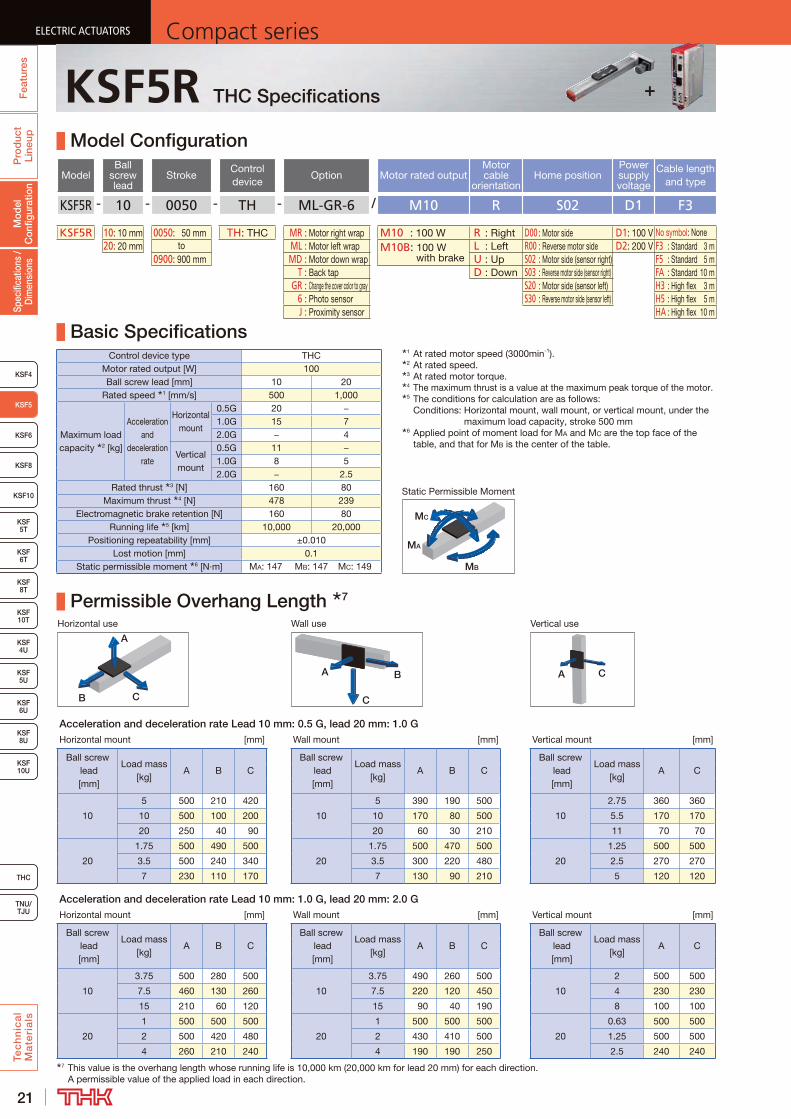
KSF5R - 10 - 0050 - TH - ML-GR-6 / M10 R S02 D1 F3
KSF5R 10: 10 mm 0050: 50 mm TH: THC MR : Motor right wrap M10 : 100 W R : Right D00 : Motor side D1: 100 V No symbol: None20: 20 mm to ML : Motor left wrap M10B: 100 W
with brakeL : Left R00 : Reverse motor side D2: 200 V F3 : Standard 3 m
0900: 900 mm MD : Motor down wrap U : Up S02 : Motor side (sensor right) F5 : Standard 5 m T : Back tap D : Down S03 : Reverse motor side (sensor right) FA : Standard 10 m GR : Change the cover color to gray S20 : Motor side (sensor left) H3 : High flex 3 m 6 : Photo sensor S30 : Reverse motor side (sensor left) H5 : High flex 5 m J : Proximity sensor HA : High flex 10 m
Basic SpecificationsControl device type THC
Motor rated output [W] 100Ball screw lead [mm] 10 20
Rated speed 1 [mm/s] 500 1,000
Maximum load capacity 2 [kg]
Acceleration and
deceleration rate
Horizontal mount
0.5G 20 −1.0G 15 72.0G − 4
Vertical mount
0.5G 11 −1.0G 8 52.0G − 2.5
Rated thrust 3 [N] 160 80Maximum thrust 4 [N] 478 239
Electromagnetic brake retention [N] 160 80Running life 5 [km] 10,000 20,000
Positioning repeatability [mm] ±0.010Lost motion [mm] 0.1
Static permissible moment 6 [N·m] MA: 147 MB: 147 MC: 149
Permissible Overhang Length 7
Horizontal use Wall use Vertical use
CB
A
A B
C
A C
Acceleration and deceleration rate Lead 10 mm: 0.5 G, lead 20 mm: 1.0 GHorizontal mount [mm] Wall mount [mm] Vertical mount [mm]
Ball screw lead [mm]
Load mass [kg]
A B CBall screw
lead [mm]
Load mass [kg]
A B CBall screw
lead [mm]
Load mass [kg]
A C
10
5 500 210 420
10
5 390 190 500
10
2.75 360 360
10 500 100 200 10 170 80 500 5.5 170 170
20 250 40 90 20 60 30 210 11 70 70
20
1.75 500 490 500
20
1.75 500 470 500
20
1.25 500 500
3.5 500 240 340 3.5 300 220 480 2.5 270 270
7 230 110 170 7 130 90 210 5 120 120
Acceleration and deceleration rate Lead 10 mm: 1.0 G, lead 20 mm: 2.0 GHorizontal mount [mm] Wall mount [mm] Vertical mount [mm]
Ball screw lead [mm]
Load mass [kg]
A B CBall screw
lead [mm]
Load mass [kg]
A B CBall screw
lead [mm]
Load mass [kg]
A C
10
3.75 500 280 500
10
3.75 490 260 500
10
2 500 500
7.5 460 130 260 7.5 220 120 450 4 230 230
15 210 60 120 15 90 40 190 8 100 100
20
1 500 500 500
20
1 500 500 500
20
0.63 500 500
2 500 420 480 2 430 410 500 1.25 500 500
4 260 210 240 4 190 190 250 2.5 240 2407 This value is the overhang length whose running life is 10,000 km (20,000 km for lead 20 mm) for each direction.
A permissible value of the applied load in each direction.
1 At rated motor speed (3000min-1).2 At rated speed.3 At rated motor torque.4 The maximum thrust is a value at the maximum peak torque of the motor.5 The conditions for calculation are as follows:
Conditions: Horizontal mount, wall mount, or vertical mount, under the maximum load capacity, stroke 500 mm
6 Applied point of moment load for MA and MC are the top face of the table, and that for MB is the center of the table.
MB
MA
MC
Static Permissible Moment
22
ELECTRIC ACTUATORSCompact series
Pro
duc
t Li
neup
Tec
hn
ica
l M
ate
ria
ls
THC
TNU/TJU
KSF8
KSF4
KSF 10T
KSF10
KSF 5T
KSF 6T
KSF 8T
KSF 10U
KSF 4U
KSF 5U
KSF 6U
KSF 8U
KSF5
KSF6
Spec
ifica
tions
/ D
imen
sion
sM
odel
C
onfig
urat
ion
Fea
ture
s
ELECTRIC ACTUATORSCompact series
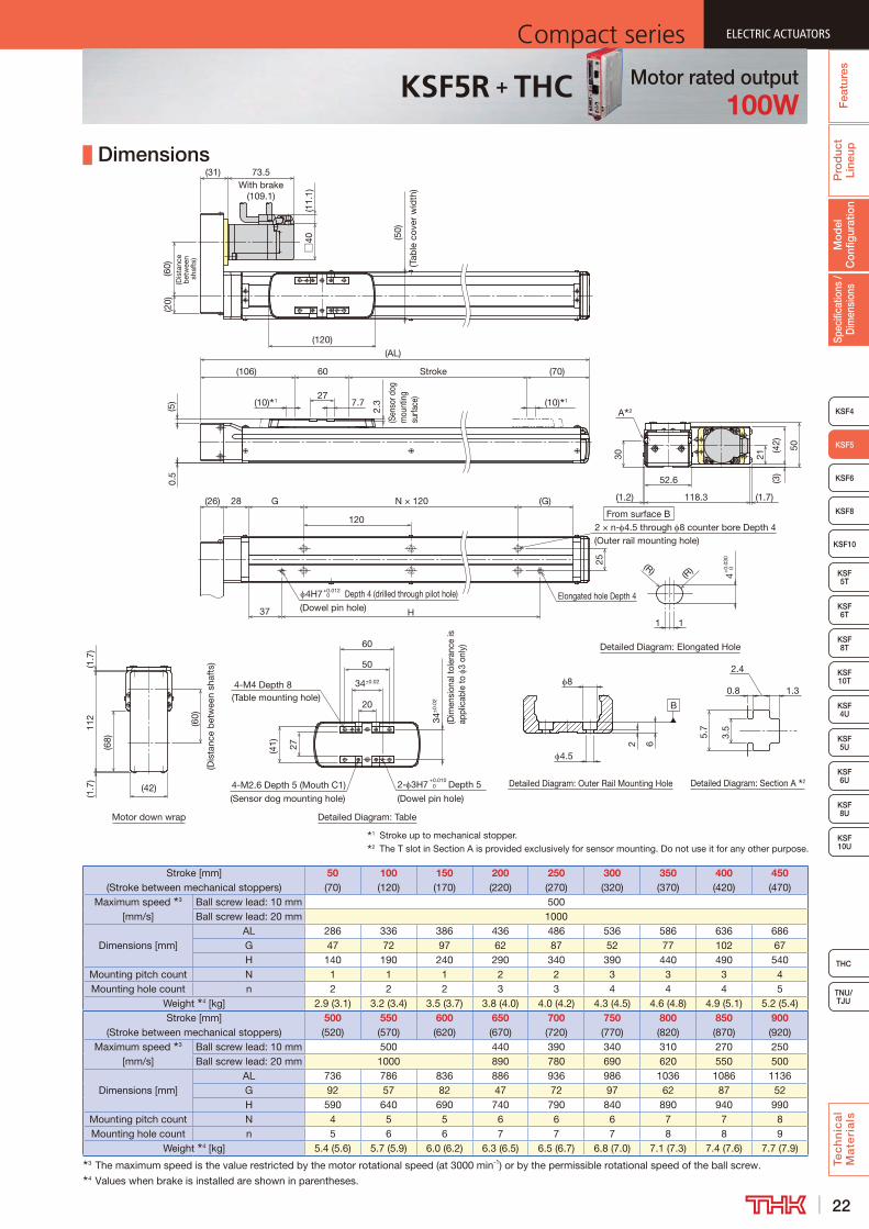
Dimensions
1 Stroke up to mechanical stopper.2 The T slot in Section A is provided exclusively for sensor mounting. Do not use it for any other purpose.
From surface B
Motor down wrap
Stroke
28(26)
(AL)
27
60(106)
(10) 1
120
G
4H7 Depth 4 (drilled through pilot hole)
(60)
(Dis
tanc
e b
etw
een
shaf
ts)
(20)
(10) 1 7.7
N × 120 (G)
37 H
2 × n- 4.5 through 8 counter bore Depth 4(Outer rail mounting hole)
25
(120)
Elongated hole Depth 4
(5)
2.3
0.5
(70)
(50)
(Tab
le c
over
wid
th)
73.5With brake
(109.1)
(31)
0+0.012
Detailed Diagram: Outer Rail Mounting Hole
Detailed Diagram: Table
B
Detailed Diagram: Elongated Hole
Detailed Diagram: Section A 2
1.30.8
2.4
3.5
5.7
8
2
4.5(41) 6
2- 3H7 Depth 5
(Dowel pin hole)
20
27
34±
0.02
(Dim
ensi
onal
tole
ranc
e is
ap
plic
able
to
3 on
ly)
4-M2.6 Depth 5 (Mouth C1)
(Sensor dog mounting hole)
4-M4 Depth 8(Table mounting hole)
50
34±0.02
60
0+0.010
4
1
(R) (R)
1
0+0.
030
(11.
1)□
40
(68)
112
(1.7
)(1
.7)
(60)
(Dis
tanc
e b
etw
een
shaf
ts)
(42)
30
(42)
52.6
(1.2) 118.3
(3)
(1.7)
50
21
A 2
(Sen
sor d
og
mou
ntin
g su
rface
)
(Dowel pin hole)
Stroke [mm] (Stroke between mechanical stoppers)
50 (70)
100 (120)
150 (170)
200 (220)
250 (270)
300 (320)
350 (370)
400 (420)
450 (470)
Maximum speed 3 [mm/s]
Ball screw lead: 10 mm 500Ball screw lead: 20 mm 1000
Dimensions [mm]AL 286 336 386 436 486 536 586 636 686G 47 72 97 62 87 52 77 102 67H 140 190 240 290 340 390 440 490 540
Mounting pitch count N 1 1 1 2 2 3 3 3 4Mounting hole count n 2 2 2 3 3 4 4 4 5
Weight 4 [kg] 2.9 (3.1) 3.2 (3.4) 3.5 (3.7) 3.8 (4.0) 4.0 (4.2) 4.3 (4.5) 4.6 (4.8) 4.9 (5.1) 5.2 (5.4)Stroke [mm]
(Stroke between mechanical stoppers)500 (520)
550 (570)
600 (620)
650 (670)
700 (720)
750 (770)
800 (820)
850 (870)
900 (920)
Maximum speed 3 [mm/s]
Ball screw lead: 10 mm 500 440 390 340 310 270 250Ball screw lead: 20 mm 1000 890 780 690 620 550 500
Dimensions [mm]AL 736 786 836 886 936 986 1036 1086 1136G 92 57 82 47 72 97 62 87 52H 590 640 690 740 790 840 890 940 990
Mounting pitch count N 4 5 5 6 6 6 7 7 8Mounting hole count n 5 6 6 7 7 7 8 8 9
Weight 4 [kg] 5.4 (5.6) 5.7 (5.9) 6.0 (6.2) 6.3 (6.5) 6.5 (6.7) 6.8 (7.0) 7.1 (7.3) 7.4 (7.6) 7.7 (7.9)3 The maximum speed is the value restricted by the motor rotational speed (at 3000 min-1) or by the permissible rotational speed of the ball screw.4 Values when brake is installed are shown in parentheses.
Motor rated output100W
KSF5R + THC
23
ELECTRIC ACTUATORS Compact seriesP
rod
uct
Line
upTe
ch
nic
al
Ma
teri
als
KSF8
KSF4
KSF 10T
KSF10
KSF 6T
KSF 8T
KSF 10U
KSF 4U
KSF 5U
KSF 6U
KSF 8U
TNU/TJU
THC
Spec
ifica
tions
/ D
imen
sion
sM
odel
C
onfig
urat
ion
Fea
ture
sELECTRIC ACTUATORS Compact series
KSF5
ELECTRIC ACTUATORS Compact series
KSF6
KSF 5T
ELECTRIC ACTUATORS Compact series
+KSF6 THC Specifications
Model Configuration
Model -Ball
screw lead
- Stroke -Control device
- Option / Motor rated outputMotor cable
orientationHome position
Power supply voltage
Cable type and length
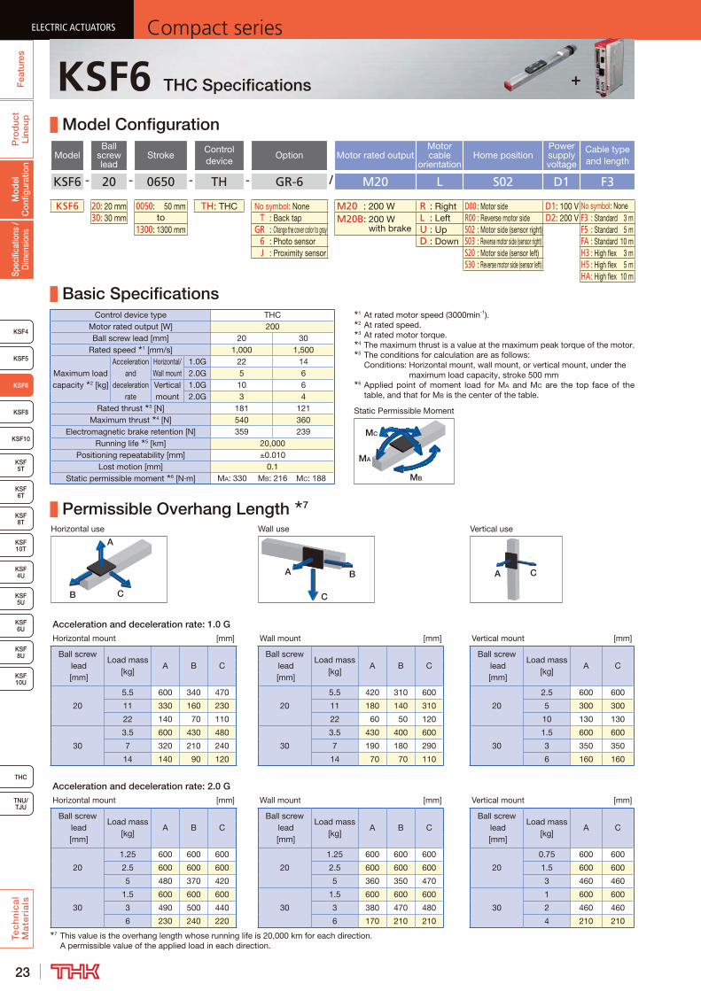
KSF6 - 20 - 0650 - TH - GR-6 / M20 L S02 D1 F3
KSF6 20: 20 mm 0050: 50 mm TH: THC No symbol: None M20 : 200 W R : Right D00 : Motor side D1: 100 V No symbol: None30: 30 mm to T : Back tap M20B: 200 W
with brakeL : Left R00 : Reverse motor side D2: 200 V F3 : Standard 3 m
1300: 1300 mm GR : Change the cover color to gray U : Up S02 : Motor side (sensor right) F5 : Standard 5 m 6 : Photo sensor D : Down S03 : Reverse motor side (sensor right) FA : Standard 10 m J : Proximity sensor S20 : Motor side (sensor left) H3 : High flex 3 m
S30 : Reverse motor side (sensor left) H5 : High flex 5 mHA : High flex 10 m
Basic SpecificationsControl device type THC
Motor rated output [W] 200Ball screw lead [mm] 20 30
Rated speed 1 [mm/s] 1,000 1,500
Maximum load capacity 2 [kg]
Acceleration and
deceleration rate
Horizontal/Wall mount
1.0G 22 142.0G 5 6
Vertical mount
1.0G 10 62.0G 3 4
Rated thrust 3 [N] 181 121Maximum thrust 4 [N] 540 360
Electromagnetic brake retention [N] 359 239Running life 5 [km] 20,000
Positioning repeatability [mm] ±0.010Lost motion [mm] 0.1
Static permissible moment 6 [N·m] MA: 330 MB: 216 MC: 188
Permissible Overhang Length 7
Horizontal use Wall use Vertical use
CB
A
A B
C
A C
Acceleration and deceleration rate: 1.0 GHorizontal mount [mm] Wall mount [mm] Vertical mount [mm]
Ball screw lead [mm]
Load mass [kg]
A B CBall screw
lead [mm]
Load mass [kg]
A B CBall screw
lead [mm]
Load mass [kg]
A C
20
5.5 600 340 470
20
5.5 420 310 600
20
2.5 600 600
11 330 160 230 11 180 140 310 5 300 300
22 140 70 110 22 60 50 120 10 130 130
30
3.5 600 430 480
30
3.5 430 400 600
30
1.5 600 600
7 320 210 240 7 190 180 290 3 350 350
14 140 90 120 14 70 70 110 6 160 160
Acceleration and deceleration rate: 2.0 GHorizontal mount [mm] Wall mount [mm] Vertical mount [mm]
Ball screw lead [mm]
Load mass [kg]
A B CBall screw
lead [mm]
Load mass [kg]
A B CBall screw
lead [mm]
Load mass [kg]
A C
20
1.25 600 600 600
20
1.25 600 600 600
20
0.75 600 600
2.5 600 600 600 2.5 600 600 600 1.5 600 600
5 480 370 420 5 360 350 470 3 460 460
30
1.5 600 600 600
30
1.5 600 600 600
30
1 600 600
3 490 500 440 3 380 470 480 2 460 460
6 230 240 220 6 170 210 210 4 210 2107 This value is the overhang length whose running life is 20,000 km for each direction.
A permissible value of the applied load in each direction.
1 At rated motor speed (3000min-1).2 At rated speed.3 At rated motor torque.4 The maximum thrust is a value at the maximum peak torque of the motor.5 The conditions for calculation are as follows:
Conditions: Horizontal mount, wall mount, or vertical mount, under the maximum load capacity, stroke 500 mm
6 Applied point of moment load for MA and MC are the top face of the table, and that for MB is the center of the table.
MB
MA
MC
Static Permissible Moment
+
24
ELECTRIC ACTUATORSCompact series
Pro
duc
t Li
neup
Tec
hn
ica
l M
ate
ria
ls
THC
TNU/TJU
KSF8
KSF4
KSF 10T
KSF10
KSF 6T
KSF 8T
KSF 10U
KSF 4U
KSF 5U
KSF 6U
KSF 8U
Spec
ifica
tions
/ D
imen
sion
sM
odel
C
onfig
urat
ion
Fea
ture
s
ELECTRIC ACTUATORSCompact series
KSF5
ELECTRIC ACTUATORSCompact series
KSF6
KSF5T
ELECTRIC ACTUATORSCompact series
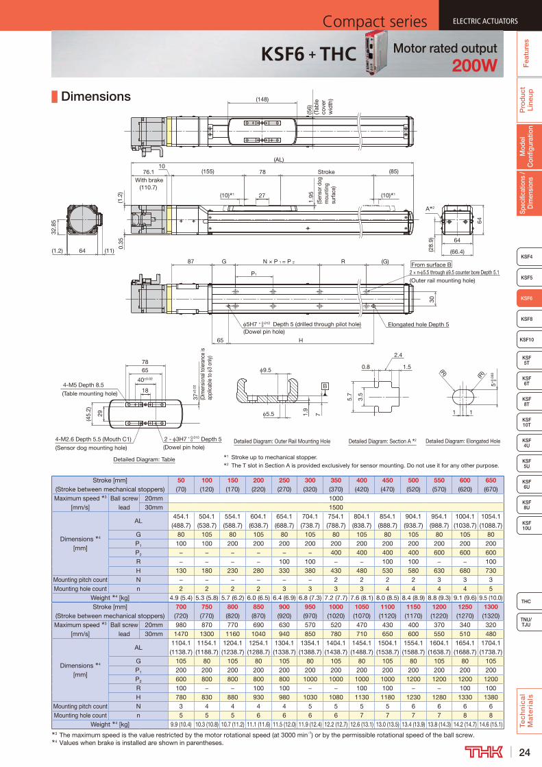
Dimensions
B
Detailed Diagram: Table
Detailed Diagram: Outer Rail Mounting Hole Detailed Diagram: Section A 2
1 Stroke up to mechanical stopper.2 The T slot in Section A is provided exclusively for sensor mounting. Do not use it for any other purpose.
(Sen
sor d
og
mou
ntin
g su
rface
)
Stroke
(10) 1
(155) (85)
7
27
1.9
A 2
64
(56)
(Tab
le
cove
r w
idth
)
64
30
G R (G)
78
P1
N × P 1 = P 2 87
(10) 1
(148)
With brake(110.7)
10
64
(AL)
(11)
5.5
9.5
(1.2
)0.
35
(28.
9)
29
37±
0.02
(Dim
ensio
nal t
oler
ance
is
appl
icab
le to
3
only)
65
40±0.02
2 - 3H7 + 0.010 0 Depth 5
(Dowel pin hole)
4-M5 Depth 8.5
(Table mounting hole) 18
4-M2.6 Depth 5.5 (Mouth C1)
(Sensor dog mounting hole)
(45.
2)
76.1
1.95
H
Detailed Diagram: Elongated Hole
65
5H7 + 0.012 0 Depth 5 (drilled through pilot hole) Elongated hole Depth 5
1 1
5+0.
030
0
(R)(R)
From surface B2 × n- 5.5 through 9.5 counter bore Depth 5.1(Outer rail mounting hole)
32.8
5
(1.2) (66.4)
78 2.4
0.8
5.7
3.5
1.5
(Dowel pin hole)
Stroke [mm] (Stroke between mechanical stoppers)
50 (70)
100 (120)
150 (170)
200 (220)
250 (270)
300 (320)
350 (370)
400 (420)
450 (470)
500 (520)
550 (570)
600 (620)
650 (670)
Maximum speed 3 [mm/s]
Ball screw lead
20mm 100030mm 1500
Dimensions 4 [mm]
AL454.1 (488.7)
504.1 (538.7)
554.1 (588.7)
604.1 (638.7)
654.1 (688.7)
704.1 (738.7)
754.1 (788.7)
804.1 (838.7)
854.1 (888.7)
904.1 (938.7)
954.1 (988.7)
1004.1 (1038.7)
1054.1 (1088.7)
G 80 105 80 105 80 105 80 105 80 105 80 105 80P1 100 100 200 200 200 200 200 200 200 200 200 200 200P2 − − − − − − 400 400 400 400 600 600 600R − − − − 100 100 − − 100 100 − − 100H 130 180 230 280 330 380 430 480 530 580 630 680 730
Mounting pitch count N − − − − − − 2 2 2 2 3 3 3Mounting hole count n 2 2 2 2 3 3 3 3 4 4 4 4 5
Weight 4 [kg] 4.9 (5.4) 5.3 (5.8) 5.7 (6.2) 6.0 (6.5) 6.4 (6.9) 6.8 (7.3) 7.2 (7.7) 7.6 (8.1) 8.0 (8.5) 8.4 (8.9) 8.8 (9.3) 9.1 (9.6) 9.5 (10.0)Stroke [mm]
(Stroke between mechanical stoppers)700 (720)
750 (770)
800 (820)
850 (870)
900 (920)
950 (970)
1000 (1020)
1050 (1070)
1100 (1120)
1150 (1170)
1200 (1220)
1250 (1270)
1300 (1320)
Maximum speed 3 [mm/s]
Ball screw lead
20mm 980 870 770 690 630 570 520 470 430 400 370 340 32030mm 1470 1300 1160 1040 940 850 780 710 650 600 550 510 480
Dimensions 4 [mm]
AL1104.1 (1138.7)
1154.1 (1188.7)
1204.1 (1238.7)
1254.1 (1288.7)
1304.1 (1338.7)
1354.1 (1388.7)
1404.1 (1438.7)
1454.1 (1488.7)
1504.1 (1538.7)
1554.1 (1588.7)
1604.1 (1638.7)
1654.1 (1688.7)
1704.1 (1738.7)
G 105 80 105 80 105 80 105 80 105 80 105 80 105P1 200 200 200 200 200 200 200 200 200 200 200 200 200P2 600 800 800 800 800 1000 1000 1000 1000 1200 1200 1200 1200R 100 − − 100 100 − − 100 100 − − 100 100H 780 830 880 930 980 1030 1080 1130 1180 1230 1280 1330 1380
Mounting pitch count N 3 4 4 4 4 5 5 5 5 6 6 6 6Mounting hole count n 5 5 5 6 6 6 6 7 7 7 7 8 8
Weight 4 [kg] 9.9 (10.4) 10.3 (10.8) 10.7 (11.2) 11.1 (11.6) 11.5 (12.0) 11.9 (12.4) 12.2 (12.7) 12.6 (13.1) 13.0 (13.5) 13.4 (13.9) 13.8 (14.3) 14.2 (14.7) 14.6 (15.1)3 The maximum speed is the value restricted by the motor rotational speed (at 3000 min-1) or by the permissible rotational speed of the ball screw.4 Values when brake is installed are shown in parentheses.
Motor rated output200W
KSF6 + THC
25
ELECTRIC ACTUATORS Compact seriesP
rod
uct
Line
upTe
ch
nic
al
Ma
teri
als
KSF8
KSF4
KSF 10T
KSF10
KSF 6T
KSF 8T
KSF 10U
KSF 4U
KSF 5U
KSF 6U
KSF 8U
TNU/TJU
THC
Spec
ifica
tions
/ D
imen
sion
sM
odel
C
onfig
urat
ion
Fea
ture
sELECTRIC ACTUATORS Compact series
KSF5
ELECTRIC ACTUATORS Compact series
KSF6
KSF 5T
ELECTRIC ACTUATORS Compact series
+KSF6R THC Specifications
Model Configuration
ModelBall
screw lead
StrokeControl device
Option Motor rated outputMotor cable
orientationHome position
Power supply voltage
Cable length and type
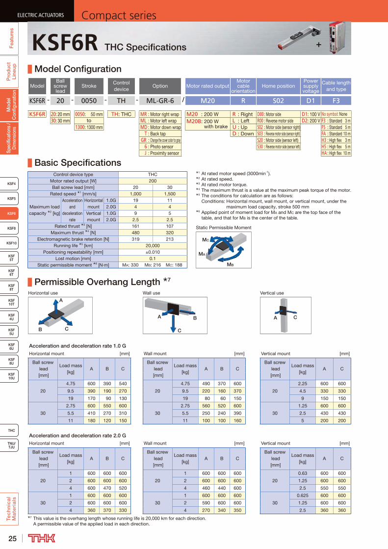
KSF6R - 20 - 0050 - TH - ML-GR-6 / M20 R S02 D1 F3
KSF6R 20: 20 mm 0050: 50 mm TH: THC MR : Motor right wrap M20 : 200 W R : Right D00 : Motor side D1: 100 V No symbol: None30: 30 mm to ML : Motor left wrap M20B: 200 W
with brakeL : Left R00 : Reverse motor side D2: 200 V F3 : Standard 3 m
1300: 1300 mm MD : Motor down wrap U : Up S02 : Motor side (sensor right) F5 : Standard 5 m T : Back tap D : Down S03 : Reverse motor side (sensor right) FA : Standard 10 m GR : Change the cover color to gray S20 : Motor side (sensor left) H3 : High flex 3 m 6 : Photo sensor S30 : Reverse motor side (sensor left) H5 : High flex 5 m J : Proximity sensor HA : High flex 10 m
Basic SpecificationsControl device type THC
Motor rated output [W] 200Ball screw lead [mm] 20 30
Rated speed 1 [mm/s] 1,000 1,500
Maximum load capacity 2 [kg]
Acceleration and
deceleration rate
Horizontal mount
1.0G 19 112.0G 4 4
Vertical mount
1.0G 9 52.0G 2.5 2.5
Rated thrust 3 [N] 161 107Maximum thrust 4 [N] 480 320
Electromagnetic brake retention [N] 319 213Running life 5 [km] 20,000
Positioning repeatability [mm] ±0.010Lost motion [mm] 0.1
Static permissible moment 6 [N·m] MA: 330 MB: 216 MC: 188
Permissible Overhang Length 7
Horizontal use Wall use Vertical use
CB
A
A B
C
A C
Acceleration and deceleration rate 1.0 GHorizontal mount [mm] Wall mount [mm] Vertical mount [mm]
Ball screw lead [mm]
Load mass [kg]
A B CBall screw
lead [mm]
Load mass [kg]
A B CBall screw
lead [mm]
Load mass [kg]
A C
20
4.75 600 390 540
20
4.75 490 370 600
20
2.25 600 600
9.5 390 190 270 9.5 220 160 370 4.5 330 330
19 170 90 130 19 80 60 150 9 150 150
30
2.75 600 550 600
30
2.75 560 520 600
30
1.25 600 600
5.5 410 270 310 5.5 250 240 390 2.5 430 430
11 180 120 150 11 100 100 160 5 200 200
Acceleration and deceleration rate 2.0 GHorizontal mount [mm] Wall mount [mm] Vertical mount [mm]
Ball screw lead [mm]
Load mass [kg]
A B CBall screw
lead [mm]
Load mass [kg]
A B CBall screw
lead [mm]
Load mass [kg]
A C
20
1 600 600 600
20
1 600 600 600
20
0.63 600 600
2 600 600 600 2 600 600 600 1.25 600 600
4 600 470 520 4 460 440 600 2.5 550 550
30
1 600 600 600
30
1 600 600 600
30
0.625 600 600
2 600 600 600 2 590 600 600 1.25 600 600
4 360 370 330 4 270 340 350 2.5 360 3607 This value is the overhang length whose running life is 20,000 km for each direction.
A permissible value of the applied load in each direction.
1 At rated motor speed (3000min-1).2 At rated speed.3 At rated motor torque.4 The maximum thrust is a value at the maximum peak torque of the motor.5 The conditions for calculation are as follows:
Conditions: Horizontal mount, wall mount, or vertical mount, under the maximum load capacity, stroke 500 mm
6 Applied point of moment load for MA and MC are the top face of the table, and that for MB is the center of the table.
MB
MA
MC
Static Permissible Moment

26
ELECTRIC ACTUATORSCompact series
Pro
duc
t Li
neup
Tec
hn
ica
l M
ate
ria
ls
THC
TNU/TJU
KSF8
KSF4
KSF 10T
KSF10
KSF 6T
KSF 8T
KSF 10U
KSF 4U
KSF 5U
KSF 6U
KSF 8U
Spec
ifica
tions
/ D
imen
sion
sM
odel
C
onfig
urat
ion
Fea
ture
s
ELECTRIC ACTUATORSCompact series
KSF5
ELECTRIC ACTUATORSCompact series
KSF6
KSF5T
ELECTRIC ACTUATORSCompact series
Dimensions
Motor down wrap
From surface B
1 Stroke up to mechanical stopper.2 The T slot in Section A is provided exclusively for sensor mounting. Do not use it for any other purpose.
(29)
(75)
(Dis
tanc
e b
etw
een
shaf
ts)
(131)
(AL)
(10) 1
78 Stroke
(10) 1
(85)
27
148
30
(G)30 N × P 1 = P 2 R
H
2 × n- 5.5 through 9.5 counter bore Depth 5.1(Outer rail mounting hole)
65
P1
G
Elongated hole Depth 55H7 Depth 5 (Drilled through pilot hole)
(56)
(Tab
le c
over
wid
th)
(33)
1.95
(Sen
sor d
og
mou
ntin
g su
rface
)
(40) 76.1With brake
(110.7)(1
.2)
0.35
0+0.012
(13)
□60
(83.
2)
(75)
(Dis
tanc
e b
etw
een
shaf
ts)
145
(60)(2)
(1.7
)
(60)
148 (2)(1.2)
(28.
9)
64
64
(2.8
)
30
A 2
Detailed Diagram: Elongated Hole
1 1
5+0.
030
0
(R)(R)
B
Detailed Diagram: Table Detailed Diagram: Outer Rail Mounting Hole Detailed Diagram: Section A 2
71.9
5.5
9.5
29
37±
0.02
(Dim
ensi
onal
to
lera
nce
is
appl
icab
le to
3
only
)
65
40±0.02
2 - 3H7 + 0.010 0 Depth 5
(Dowel pin hole)
4-M5 Depth 8.5
(Table mounting hole) 18
4-M2.6 Depth 5.5 (Mouth C1)
(Sensor dog mounting hole)
(45.
2)
78
2.4
0.8
5.7
3.5
1.5
(Dowel pin hole)
Stroke [mm] (Stroke between mechanical stoppers)
50 (70)
100 (120)
150 (170)
200 (220)
250 (270)
300 (320)
350 (370)
400 (420)
450 (470)
500 (520)
550 (570)
600 (620)
650 (670)
Maximum speed 3 [mm/s]
Ball screw lead: 20 mm 1000
Ball screw lead: 30 mm 1500
Dimensions [mm]
AL 344 394 444 494 544 594 644 694 744 794 844 894 944G 80 105 80 105 80 105 80 105 80 105 80 105 80P1 100 100 200 200 200 200 200 200 200 200 200 200 200P2 − − − − − − 400 400 400 400 600 600 600R − − − − 100 100 − − 100 100 − − 100H 130 180 230 280 330 380 430 480 530 580 630 680 730
Mounting pitch count N − − − − − − 2 2 2 2 3 3 3Mounting hole count n 2 2 2 2 3 3 3 3 4 4 4 4 5
Weight 4 [kg] 5.4 (5.9) 5.8 (6.3) 6.2 (6.7) 6.5 (7.0) 6.9 (7.4) 7.3 (7.8) 7.7 (8.2) 8.1 (8.6) 8.5 (9.0) 8.9 (9.4) 9.3 (9.8) 9.6 (10.1) 10.0 (10.5)Stroke [mm]
(Stroke between mechanical stoppers)700 (720)
750 (770)
800 (820)
850 (870)
900 (920)
950 (970)
1000 (1020)
1050 (1070)
1100 (1120)
1150 (1170)
1200 (1220)
1250 (1270)
1300 (1320)
Maximum speed 3 [mm/s]
Ball screw lead: 20 mm 980 870 770 690 630 570 520 470 430 400 370 340 320Ball screw lead: 30 mm 1470 1300 1160 1040 940 850 780 710 650 600 550 510 480
Dimensions [mm]
AL 994 1044 1094 1144 1194 1244 1294 1344 1394 1444 1494 1544 1594G 105 80 105 80 105 80 105 80 105 80 105 80 105P1 200 200 200 200 200 200 200 200 200 200 200 200 200P2 600 800 800 800 800 1000 1000 1000 1000 1200 1200 1200 1200R 100 − − 100 100 − − 100 100 − − 100 100H 780 830 880 930 980 1030 1080 1130 1180 1230 1280 1330 1380
Mounting pitch count N 3 4 4 4 4 5 5 5 5 6 6 6 6Mounting hole count n 5 5 5 6 6 6 6 7 7 7 7 8 8
Weight 4 [kg] 10.4 (10.9) 10.8 (11.3) 11.2 (11.7) 11.6 (12.1) 12.0 (12.5) 12.4 (12.9) 12.7 (13.2) 13.1 (13.6) 13.5 (14.0) 13.9 (14.4) 14.3 (14.8) 14.7 (15.2) 15.1 (15.6)3 The maximum speed is the value restricted by the motor rotational speed (at 3000 min-1) or by the permissible rotational speed of the ball screw.4 Values when brake is installed are shown in parentheses.
Motor rated output200W
KSF6R + THC

27
ELECTRIC ACTUATORS Compact seriesP
rod
uct
Line
upTe
ch
nic
al
Ma
teri
als
KSF4
KSF10
KSF 5T
KSF 6T
KSF 8T
KSF 10U
KSF 4U
KSF 5U
KSF 6U
KSF 8U
TNU/TJU
THC
Spec
ifica
tions
/ D
imen
sion
sM
odel
C
onfig
urat
ion
Fea
ture
sELECTRIC ACTUATORS Compact series
KSF5
KSF6
ELECTRIC ACTUATORS Compact series
KSF8
KSF 10T
ELECTRIC ACTUATORS Compact series
+KSF8 THC Specifications
Model Configuration
ModelBall
screw lead
StrokeControl device
Option / Motor rated outputMotor cable
orientationHome position
Power supply voltage
Cable length and type
KSF8 - 20 - 0700 - TH - GR-6 / M40 L S02 D1 F3
KSF8 20: 20 mm 0100: 100 mm TH: THC No symbol: None M40 : 400 W R : Right D00 : Motor side D1: 100 V No symbol: None40: 40 mm to T : Back tap M40B: 400 W
with brakeL : Left R00 : Reverse motor side D2: 200 V F3 : Standard 3 m
1500: 1500 mm GR : Change the cover color to gray U : Up S02 : Motor side (sensor right) F5 : Standard 5 m 6 : Photo sensor D : Down S03 : Reverse motor side (sensor right) FA : Standard 10 m J : Proximity sensor S20 : Motor side (sensor left) H3 : High flex 3 m
S30 : Reverse motor side (sensor left) H5 : High flex 5 mHA : High flex 10 m
Basic SpecificationsControl device type THC
Motor rated output [W] 400Ball screw lead [mm] 20 40
Rated speed 1 [mm/s] 1,000 2,000
Maximum load capacity 2 [kg]
Acceleration and
deceleration rate
Horizontal mount
1.0G 43 162.0G 6 7
Vertical mount
1.0G 20 82.0G 3 5
Rated thrust 3 [N] 359 180Maximum thrust 4 [N] 1080 540
Electromagnetic brake retention [N] 359 180Running life 5 [km] 20,000
Positioning repeatability [mm] ±0.010Lost motion [mm] 0.1
Static permissible moment 6 [N·m] MA: 730 MB: 437 MC: 387
Permissible Overhang Length 7
Horizontal use Wall use Vertical use
CB
A
A B
C
A C
Acceleration and deceleration rate 1.0 GHorizontal mount [mm] Wall mount [mm] Vertical mount [mm]
Ball screw lead [mm]
Load mass [kg]
A B CBall screw
lead [mm]
Load mass [kg]
A B CBall screw
lead [mm]
Load mass [kg]
A C
20
10.75 730 350 510
20
10.75 450 330 710
20
5 630 630
21.5 340 160 250 21.5 200 190 420 10 290 290
43 140 70 120 43 70 50 120 20 130 130
40
4 800 800 770
40
4 710 780 800
40
2 800 800
8 500 390 390 8 330 360 480 4 500 500
16 220 180 200 16 140 160 200 8 230 230
Acceleration and deceleration rate 2.0 GHorizontal mount [mm] Wall mount [mm] Vertical mount [mm]
Ball screw lead [mm]
Load mass [kg]
A B CBall screw
lead [mm]
Load mass [kg]
A B CBall screw
lead [mm]
Load mass [kg]
A C
20
1.5 800 800 800
20
1.5 800 800 800
20
0.75 800 800
3 800 800 800 3 800 800 800 1.5 800 800
6 650 500 560 6 500 470 640 3 740 740
40
1.75 800 800 800
40
1.75 800 800 800
40
1.25 800 800
3.5 750 800 670 3.5 600 800 740 2.5 680 680
7 350 450 340 7 280 420 340 5 320 3207 This value is the overhang length whose running life is 20,000 km for each direction.
A permissible value of the applied load in each direction.
1 At rated motor speed (3000min-1).2 At rated speed.3 At rated motor torque.4 The maximum thrust is a value at the maximum peak torque of the motor.5 The conditions for calculation are as follows:
Conditions: Horizontal mount, wall mount, or vertical mount, under the maximum load capacity, stroke 500 mm
6 Applied point of moment load for MA and MC are the top face of the table, and that for MB is the center of the table.
MB
MA
MC
Static Permissible Moment
+
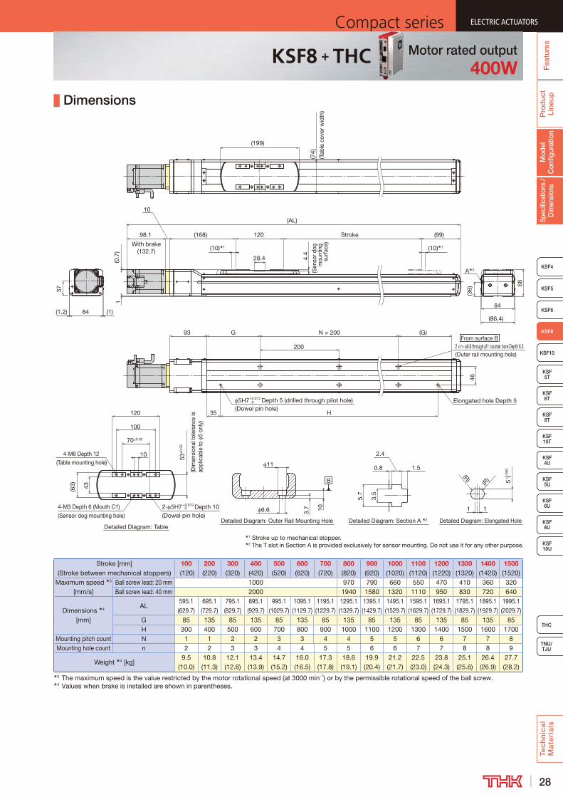
28
ELECTRIC ACTUATORSCompact series
Pro
duc
t Li
neup
Tec
hn
ica
l M
ate
ria
ls
THC
TNU/TJU
KSF4
KSF10
KSF 5T
KSF 6T
KSF 8T
KSF 10U
KSF 4U
KSF 5U
KSF 6U
KSF 8U
Spec
ifica
tions
/ D
imen
sion
sM
odel
C
onfig
urat
ion
Fea
ture
s
ELECTRIC ACTUATORSCompact series
KSF5
KSF6
ELECTRIC ACTUATORSCompact series
KSF8
KSF 10T
ELECTRIC ACTUATORSCompact series
Dimensions
From surface B
Detailed Diagram: Elongated HoleDetailed Diagram: Section A 2Detailed Diagram: Outer Rail Mounting HoleDetailed Diagram: Table
1 Stroke up to mechanical stopper.2 The T slot in Section A is provided exclusively for sensor mounting. Do not use it for any other purpose.
5.7
3.5
1.5
2.4
0.8
(168) Stroke
84
(86.4)
68
(0.7
)1
28.4
(10) 1
(99)
Elongated hole Depth 5
46
H
5H7+0.012 0 Depth 5 (drilled through pilot hole)
35
(G)N × 200G93
(10) 1
120
200
(199)
3.7
2 × n - 6.6 through 11 counter bore Depth 6.3(Outer rail mounting hole)
4.4
(Sen
sor d
og
mou
ntin
g su
rface
)106.6
11
(74)
(Tab
le c
over
wid
th)
70±0.02
2- 5H7+0.0120 Depth 10
(Dowel pin hole)4-M3 Depth 6 (Mouth C1)
(Sensor dog mounting hole)
4-M6 Depth 12(Table mounting hole)
53±
0.02
(Dim
ensi
onal
tole
ranc
e is
ap
plic
able
to
5 on
ly)
10
100
(36)
11
(63) 43
(R)
(R) 5+
0.03
0 0
A 2
(1.2) 84
10
98.1
With brake(132.7)
(AL)
(1)
120
37
B
(Dowel pin hole)
Stroke [mm] (Stroke between mechanical stoppers)
100 (120)
200 (220)
300 (320)
400 (420)
500 (520)
600 (620)
700 (720)
800 (820)
900 (920)
1000 (1020)
1100 (1120)
1200 (1220)
1300 (1320)
1400 (1420)
1500 (1520)
Maximum speed 3 [mm/s]
Ball screw lead: 20 mm 1000 970 790 660 550 470 410 360 320Ball screw lead: 40 mm 2000 1940 1580 1320 1110 950 830 720 640
Dimensions 4 [mm]
AL595.1 (629.7)
695.1 (729.7)
795.1 (829.7)
895.1 (929.7)
995.1 (1029.7)
1095.1 (1129.7)
1195.1 (1229.7)
1295.1 (1329.7)
1395.1 (1429.7)
1495.1 (1529.7)
1595.1 (1629.7)
1695.1 (1729.7)
1795.1 (1829.7)
1895.1 (1929.7)
1995.1 (2029.7)
G 85 135 85 135 85 135 85 135 85 135 85 135 85 135 85H 300 400 500 600 700 800 900 1000 1100 1200 1300 1400 1500 1600 1700
Mounting pitch count N 1 1 2 2 3 3 4 4 5 5 6 6 7 7 8Mounting hole count n 2 2 3 3 4 4 5 5 6 6 7 7 8 8 9
Weight 4 [kg]9.5
(10.0)10.8 (11.3)
12.1 (12.6)
13.4 (13.9)
14.7 (15.2)
16.0 (16.5)
17.3 (17.8)
18.6 (19.1)
19.9 (20.4)
21.2 (21.7)
22.5 (23.0)
23.8 (24.3)
25.1 (25.6)
26.4 (26.9)
27.7 (28.2)
3 The maximum speed is the value restricted by the motor rotational speed (at 3000 min-1) or by the permissible rotational speed of the ball screw.4 Values when brake is installed are shown in parentheses.
Motor rated output400W
KSF8 + THC

29
ELECTRIC ACTUATORS Compact seriesP
rod
uct
Line
upTe
ch
nic
al
Ma
teri
als
KSF4
KSF10
KSF 5T
KSF 6T
KSF 8T
KSF 10U
KSF 4U
KSF 5U
KSF 6U
KSF 8U
TNU/TJU
THC
Spec
ifica
tions
/ D
imen
sion
sM
odel
C
onfig
urat
ion
Fea
ture
sELECTRIC ACTUATORS Compact series
KSF5
KSF6
ELECTRIC ACTUATORS Compact series
KSF8
KSF 10T
ELECTRIC ACTUATORS Compact series
+KSF8R THC Specifications
Model Configuration
ModelBall
screw lead
StrokeControl device
Option Motor rated outputMotor cable
orientationHome position
Power supply voltage
Cable length and type
KSF8R - 20 - 0700 - TH - ML-GR-6 / M40 R S02 D1 F3
KSF8R 20: 20 mm 0100: 100 mm TH: THC MR : Motor right wrap M40 : 400 W R : Right D00 : Motor side D1: 100 V No symbol: None40: 40 mm to ML : Motor left wrap M40B: 400 W
with brakeL : Left R00 : Reverse motor side D2: 200 V F3 : Standard 3 m
1500: 1500 mm MD : Motor down wrap U : Up S02 : Motor side (sensor right) F5 : Standard 5 m T : Back tap D : Down S03 : Reverse motor side (sensor right) FA : Standard 10 m GR : Change the cover color to gray S20 : Motor side (sensor left) H3 : High flex 3 m 6 : Photo sensor S30 : Reverse motor side (sensor left) H5 : High flex 5 m J : Proximity sensor HA : High flex 10 m
Basic SpecificationsControl device type THC
Motor rated output [W] 400Ball screw lead [mm] 20 40
Rated speed 1 [mm/s] 1,000 2,000
Maximum load capacity 2 [kg]
Acceleration and
deceleration rate
Horizontal mount
1.0G 41 162.0G 6 7
Vertical mount
1.0G 20 82.0G 3 5
Rated thrust 3 [N] 319 160Maximum thrust 4 [N] 960 480
Electromagnetic brake retention [N] 319 160Running life 5 [km] 20,000
Positioning repeatability [mm] ±0.010Lost motion [mm] 0.1
Static permissible moment 6 [N·m] MA: 730 MB: 437 MC: 387
Permissible Overhang Length 7
Horizontal use Wall use Vertical use
CB
A
A B
C
A C
Acceleration and deceleration rate 1.0 GHorizontal mount [mm] Wall mount [mm] Vertical mount [mm]
Ball screw lead [mm]
Load mass [kg]
A B CBall screw
lead [mm]
Load mass [kg]
A B CBall screw
lead [mm]
Load mass [kg]
A C
20
10.25 800 520 670
20
10.25 620 490 800
20
5 630 630
20.5 520 250 330 20.5 280 220 500 10 290 290
41 230 110 160 41 110 90 210 20 130 130
40
4 800 800 770
40
4 710 780 800
40
2 800 800
8 500 390 390 8 330 360 480 4 500 500
16 220 180 200 16 140 160 200 8 230 230
Acceleration and deceleration rate 2.0 GHorizontal mount [mm] Wall mount [mm] Vertical mount [mm]
Ball screw lead [mm]
Load mass [kg]
A B CBall screw
lead [mm]
Load mass [kg]
A B CBall screw
lead [mm]
Load mass [kg]
A C
20
1.5 800 800 800
20
1.5 800 800 800
20
0.75 800 800
3 800 800 800 3 800 800 800 1.5 800 800
6 650 500 560 6 500 470 640 3 740 740
40
1.75 800 800 800
40
1.75 800 800 800
40
1.25 800 800
3.5 750 800 670 3.5 600 800 740 2.5 680 680
7 350 450 340 7 280 420 340 5 320 3207 This value is the overhang length whose running life is 20,000 km for each direction.
A permissible value of the applied load in each direction.
1 At rated motor speed (3000min-1).2 At rated speed.3 At rated motor torque.4 The maximum thrust is a value at the maximum peak torque of the motor.5 The conditions for calculation are as follows:
Conditions: Horizontal mount, wall mount, or vertical mount, under the maximum load capacity, stroke 500 mm
6 Applied point of moment load for MA and MC are the top face of the table, and that for MB is the center of the table.
MB
MA
MC
Static Permissible Moment
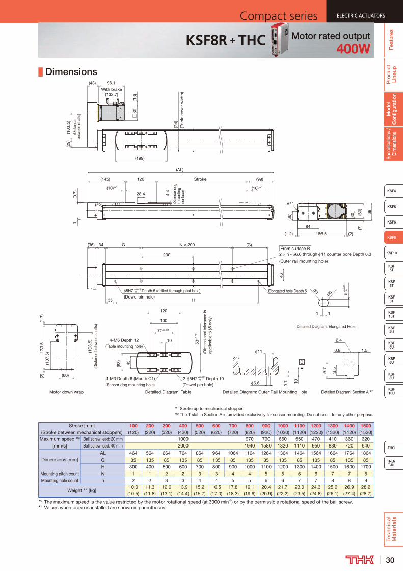
30
ELECTRIC ACTUATORSCompact series
Pro
duc
t Li
neup
Tec
hn
ica
l M
ate
ria
ls
THC
TNU/TJU
KSF4
KSF10
KSF 5T
KSF 6T
KSF 8T
KSF 10U
KSF 4U
KSF 5U
KSF 6U
KSF 8U
Spec
ifica
tions
/ D
imen
sion
sM
odel
C
onfig
urat
ion
Fea
ture
s
ELECTRIC ACTUATORSCompact series
KSF5
KSF6
ELECTRIC ACTUATORSCompact series
KSF8
KSF 10T
ELECTRIC ACTUATORSCompact series
Dimensions
From surface B
Motor down wrap
1 Stroke up to mechanical stopper.2 The T slot in Section A is provided exclusively for sensor mounting. Do not use it for any other purpose.
Stroke
(0.7
)1
28.4(10) 1
(99)
Elongated hole Depth 5
46
H
5H7 +0.012 0 Depth 5 (drilled through pilot hole)
(AL)
35
(G)N × 200G
(10) 1
120(145)
200
(199)
2 × n - 6.6 through 11 counter bore Depth 6.3
(Outer rail mounting hole)
4.4
(Sen
sor d
og
mou
ntin
g su
rface
)
(74)
(Tab
le c
over
wid
th)
34(36)
(29)
(103
.5)
(Dis
tanc
e be
twee
n sh
afts
)(43) 98.1
With brake(132.7)
(13)
□60
(1.7
)
(103
.5)
(Dis
tanc
e be
twee
n sh
afts
)
(107
.5)17
3.5
(60)(2)
30
(2)
68(60)
(1.2) 186.5
84
(36)
A 2
(7)
Detailed Diagram: Elongated Hole
Detailed Diagram: Section A 2Detailed Diagram: Outer Rail Mounting HoleDetailed Diagram: Table
5.7
3.5
1.5
2.4
0.8
3.7 106.6
11
70±0.02
2- 5H7 +0.0120 Depth 10
(Dowel pin hole)4-M3 Depth 6 (Mouth C1)(Sensor dog mounting hole)
4-M6 Depth 12(Table mounting hole)
53±
0.02
(Dim
ensi
onal
tole
ranc
e is
ap
plic
able
to
5 on
ly)
10
100
11
(63) 43
(R)
(R) 5+
0.03
0 0
120
B
(Dowel pin hole)
Stroke [mm] (Stroke between mechanical stoppers)
100 (120)
200 (220)
300 (320)
400 (420)
500 (520)
600 (620)
700 (720)
800 (820)
900 (920)
1000 (1020)
1100 (1120)
1200 (1220)
1300 (1320)
1400 (1420)
1500 (1520)
Maximum speed 3 [mm/s]
Ball screw lead: 20 mm 1000 970 790 660 550 470 410 360 320Ball screw lead: 40 mm 2000 1940 1580 1320 1110 950 830 720 640
Dimensions [mm]AL 464 564 664 764 864 964 1064 1164 1264 1364 1464 1564 1664 1764 1864
G 85 135 85 135 85 135 85 135 85 135 85 135 85 135 85H 300 400 500 600 700 800 900 1000 1100 1200 1300 1400 1500 1600 1700
Mounting pitch count N 1 1 2 2 3 3 4 4 5 5 6 6 7 7 8Mounting hole count n 2 2 3 3 4 4 5 5 6 6 7 7 8 8 9
Weight 4 [kg]10.0 (10.5)
11.3 (11.8)
12.6 (13.1)
13.9 (14.4)
15.2 (15.7)
16.5 (17.0)
17.8 (18.3)
19.1 (19.6)
20.4 (20.9)
21.7 (22.2)
23.0 (23.5)
24.3 (24.8)
25.6 (26.1)
26.9 (27.4)
28.2 (28.7)
3 The maximum speed is the value restricted by the motor rotational speed (at 3000 min-1) or by the permissible rotational speed of the ball screw.4 Values when brake is installed are shown in parentheses.
Motor rated output400W
KSF8R + THC

31
ELECTRIC ACTUATORS Compact seriesP
rod
uct
Line
upTe
ch
nic
al
Ma
teri
als
KSF8
KSF4
KSF 10T
KSF 5T
KSF 6T
KSF 8T
KSF 10U
KSF 4U
KSF 5U
KSF 8U
TNU/TJU
THC
Spec
ifica
tions
/ D
imen
sion
sM
odel
C
onfig
urat
ion
Fea
ture
sELECTRIC ACTUATORS Compact series
KSF5
KSF6
ELECTRIC ACTUATORS Compact series
KSF10
KSF 6U
ELECTRIC ACTUATORS Compact series
+KSF10 THC Specifications
Model Configuration
ModelBall
screw lead
StrokeControl device
Option Motor rated outputMotor cable
orientationHome position
Power supply voltage
Cable length and type
KSF10 - 25 - 0700 - TH - GR-6 / M75 L S02 D2 F3
KSF10 25: 25 mm 0100: 100 mm TH: THC No symbol: None M75 : 750 W R : Right D00 : Motor side D2: 200 V No symbol: None50: 50 mm to T : Back tap M75B: 750 W
with brakeL : Left R00 : Reverse motor side F3 : Standard 3 m
1500: 1500 mm GR : Change the cover color to gray U : Up S02 : Motor side (sensor right) F5 : Standard 5 m 6 : Photo sensor D : Down S03 : Reverse motor side (sensor right) FA : Standard 10 m J : Proximity sensor S20 : Motor side (sensor left) H3 : High flex 3 m
S30 : Reverse motor side (sensor left) H5 : High flex 5 mHA : High flex 10 m
Basic SpecificationsControl device type THC
Motor rated output [W] 750Ball screw lead [mm] 25 50
Rated speed 1 [mm/s] 1,250 2,500
Maximum load capacity 2 [kg]
Acceleration and
deceleration rate
Horizontal mount
1.0G 60 171.5G 26 8
Vertical mount
1.0G 25 91.5G 13 5
Rated thrust 3 [N] 541 270Maximum thrust 4 [N] 1,620 810
Electromagnetic brake retention [N] 541 270Running life 5 [km] 20,000
Positioning repeatability [mm] ±0.010Lost motion [mm] 0.1
Static permissible moment 6 [N·m] MA: 1,049 MB: 712 MC: 671
Permissible Overhang Length 7
Horizontal use Wall use Vertical use
CB
A
A B
C
A C
Acceleration and deceleration rate 1.0 GHorizontal mount [mm] Wall mount [mm] Vertical mount [mm]
Ball screw lead [mm]
Load mass [kg]
A B CBall screw
lead [mm]
Load mass [kg]
A B CBall screw
lead [mm]
Load mass [kg]
A C
25
15 1000 760 900
25
15 840 730 1000
25
6.25 1000 1000
30 660 370 450 30 390 330 630 12.5 710 710
60 300 170 220 60 160 140 270 25 330 330
50
4.25 1000 1000 1000
50
4.25 1000 1000 1000
50
2.25 1000 1000
8.5 1000 1000 850 8.5 790 1000 1000 4.5 1000 1000
17 580 530 430 17 360 490 550 9 580 580
Acceleration and deceleration rate 1.5 GHorizontal mount [mm] Wall mount [mm] Vertical mount [mm]
Ball screw lead [mm]
Load mass [kg]
A B CBall screw
lead [mm]
Load mass [kg]
A B CBall screw
lead [mm]
Load mass [kg]
A C
25
5.25 1000 1000 1000
25
5.25 1000 1000 1000
25
2.75 1000 1000
10.5 1000 1000 1000 10.5 1000 1000 1000 5.5 1000 1000
21 600 540 520 21 600 540 520 11 700 700
50
1.75 1000 1000 1000
50
1.75 1000 1000 1000
50
1 1000 1000
3.5 1000 1000 1000 3.5 1000 1000 1000 2 1000 1000
7 930 1000 800 7 720 1000 910 4 1000 10007 This value is the overhang length whose running life is 20,000 km for each direction.
A permissible value of the applied load in each direction.
1 At rated motor speed (3000min-1).2 At rated speed.3 At rated motor torque.4 The maximum thrust is a value at the maximum peak torque of the motor.5 The conditions for calculation are as follows:
Conditions: Horizontal mount, wall mount, or vertical mount, under the maximum load capacity, stroke 500 mm
6 Applied point of moment load for MA and MC are the top face of the table, and that for MB is the center of the table.
MB
MA
MC
Static Permissible Moment
+
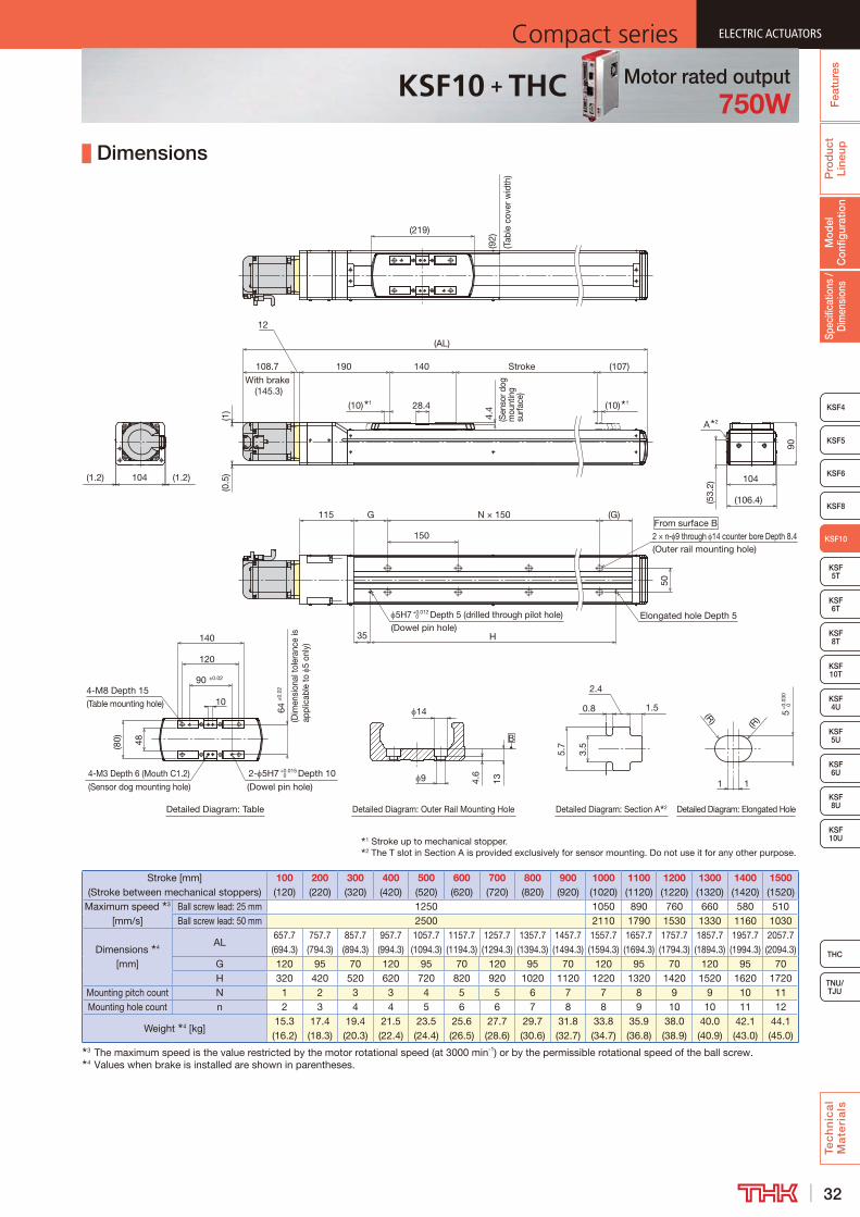
32
ELECTRIC ACTUATORSCompact series
Pro
duc
t Li
neup
Tec
hn
ica
l M
ate
ria
ls
THC
TNU/TJU
KSF8
KSF4
KSF 10T
KSF 5T
KSF 6T
KSF 8T
KSF 10U
KSF 4U
KSF 5U
KSF 8U
Spec
ifica
tions
/ D
imen
sion
sM
odel
C
onfig
urat
ion
Fea
ture
s
ELECTRIC ACTUATORSCompact series
KSF5
KSF6
ELECTRIC ACTUATORSCompact series
KSF10
KSF 6U
ELECTRIC ACTUATORSCompact series
Dimensions
1 Stroke up to mechanical stopper.2 The T slot in Section A is provided exclusively for sensor mounting. Do not use it for any other purpose.
B
Detailed Diagram: Elongated HoleDetailed Diagram: Section A 2Detailed Diagram: Outer Rail Mounting HoleDetailed Diagram: Table
From surface B
(219)
35
115
150
G (G)
H
Elongated hole Depth 55H7 +0.012 0 Depth 5 (drilled through pilot hole)
50
2 × n- 9 through 14 counter bore Depth 8.4(Outer rail mounting hole)
1 15
+0.
030
0
(R)
(R)
104
(106.4)
90
N × 150
12
108.7
With brake (145.3)
(AL)
4-M3 Depth 6 (Mouth C1.2)(Sensor dog mounting hole)
64±
0.02
(Dim
ensi
onal
tole
ranc
e is
ap
plic
able
to
5 on
ly)
2- 5H7 +0.015 0 Depth 10
(Dowel pin hole)
(Dowel pin hole)
120
90 ±0.02
4-M8 Depth 15(Table mounting hole) 10
14
9
(92)
(Tab
le c
over
wid
th)
28.4(10) 1 (10) 1
4.4
(Sen
sor d
og
mou
ntin
g su
rface
)
140190 Stroke (107)
(53.
2)
134.6
0.8
2.4
1.5
3.5
5.7
A 2
(1.2) 104 (1.2)
(1)
(0.5
)
140
48(80)
Stroke [mm] (Stroke between mechanical stoppers)
100 (120)
200 (220)
300 (320)
400 (420)
500 (520)
600 (620)
700 (720)
800 (820)
900 (920)
1000 (1020)
1100 (1120)
1200 (1220)
1300 (1320)
1400 (1420)
1500 (1520)
Maximum speed 3 [mm/s]
Ball screw lead: 25 mm 1250 1050 890 760 660 580 510Ball screw lead: 50 mm 2500 2110 1790 1530 1330 1160 1030
Dimensions 4 [mm]
AL657.7 (694.3)
757.7 (794.3)
857.7 (894.3)
957.7 (994.3)
1057.7 (1094.3)
1157.7 (1194.3)
1257.7 (1294.3)
1357.7 (1394.3)
1457.7 (1494.3)
1557.7 (1594.3)
1657.7 (1694.3)
1757.7 (1794.3)
1857.7 (1894.3)
1957.7 (1994.3)
2057.7 (2094.3)
G 120 95 70 120 95 70 120 95 70 120 95 70 120 95 70H 320 420 520 620 720 820 920 1020 1120 1220 1320 1420 1520 1620 1720
Mounting pitch count N 1 2 3 3 4 5 5 6 7 7 8 9 9 10 11Mounting hole count n 2 3 4 4 5 6 6 7 8 8 9 10 10 11 12
Weight 4 [kg]15.3 (16.2)
17.4 (18.3)
19.4 (20.3)
21.5 (22.4)
23.5 (24.4)
25.6 (26.5)
27.7 (28.6)
29.7 (30.6)
31.8 (32.7)
33.8 (34.7)
35.9 (36.8)
38.0 (38.9)
40.0 (40.9)
42.1 (43.0)
44.1 (45.0)
3 The maximum speed is the value restricted by the motor rotational speed (at 3000 min-1) or by the permissible rotational speed of the ball screw.4 Values when brake is installed are shown in parentheses.
Motor rated output750W
KSF10 + THC
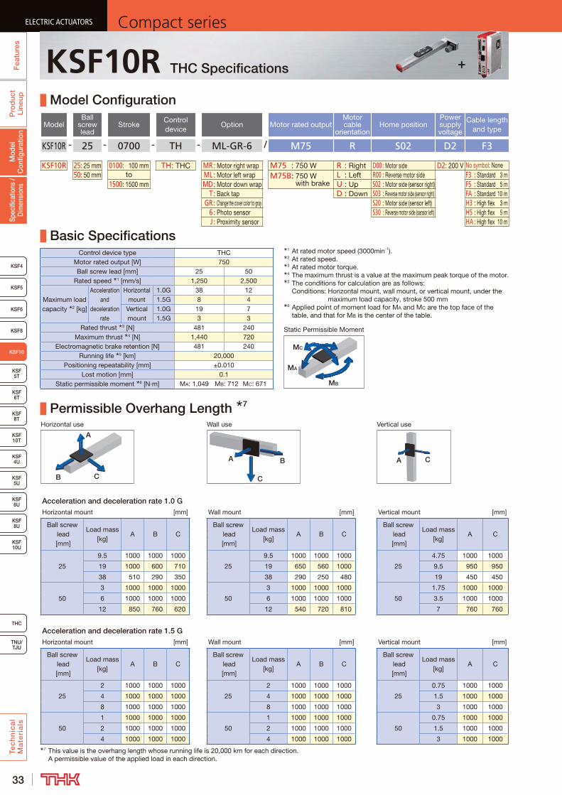
33
ELECTRIC ACTUATORS Compact seriesP
rod
uct
Line
upTe
ch
nic
al
Ma
teri
als
KSF8
KSF4
KSF 10T
KSF 5T
KSF 6T
KSF 8T
KSF 10U
KSF 4U
KSF 5U
KSF 8U
TNU/TJU
THC
Spec
ifica
tions
/ D
imen
sion
sM
odel
C
onfig
urat
ion
Fea
ture
sELECTRIC ACTUATORS Compact series
KSF5
KSF6
ELECTRIC ACTUATORS Compact series
KSF10
KSF 6U
ELECTRIC ACTUATORS Compact series
+KSF10R THC Specifications
Model Configuration
ModelBall
screw lead
StrokeControl device
Option Motor rated outputMotor cable
orientationHome position
Power supply voltage
Cable length and type
KSF10R - 25 - 0700 - TH - ML-GR-6 / M75 R S02 D2 F3
KSF10R 25: 25 mm 0100: 100 mm TH: THC MR : Motor right wrap M75 : 750 W R : Right D00 : Motor side D2: 200 V No symbol: None50: 50 mm to ML : Motor left wrap M75B: 750 W
with brakeL : Left R00 : Reverse motor side F3 : Standard 3 m
1500: 1500 mm MD : Motor down wrap U : Up S02 : Motor side (sensor right) F5 : Standard 5 m T : Back tap D : Down S03 : Reverse motor side (sensor right) FA : Standard 10 m GR : Change the cover color to gray S20 : Motor side (sensor left) H3 : High flex 3 m 6 : Photo sensor S30 : Reverse motor side (sensor left) H5 : High flex 5 m J : Proximity sensor HA : High flex 10 m
Basic SpecificationsControl device type THC
Motor rated output [W] 750Ball screw lead [mm] 25 50
Rated speed 1 [mm/s] 1,250 2,500
Maximum load capacity 2 [kg]
Acceleration and
deceleration rate
Horizontal mount
1.0G 38 121.5G 8 4
Vertical mount
1.0G 19 71.5G 3 3
Rated thrust 3 [N] 481 240Maximum thrust 4 [N] 1,440 720
Electromagnetic brake retention [N] 481 240Running life 5 [km] 20,000
Positioning repeatability [mm] ±0.010Lost motion [mm] 0.1
Static permissible moment 6 [N·m] MA: 1,049 MB: 712 MC: 671
Permissible Overhang Length 7
Horizontal use Wall use Vertical use
CB
A
A B
C
A C
Acceleration and deceleration rate 1.0 GHorizontal mount [mm] Wall mount [mm] Vertical mount [mm]
Ball screw lead [mm]
Load mass [kg]
A B CBall screw
lead [mm]
Load mass [kg]
A B CBall screw
lead [mm]
Load mass [kg]
A C
25
9.5 1000 1000 1000
25
9.5 1000 1000 1000
25
4.75 1000 1000
19 1000 600 710 19 650 560 1000 9.5 950 950
38 510 290 350 38 290 250 480 19 450 450
50
3 1000 1000 1000
50
3 1000 1000 1000
50
1.75 1000 1000
6 1000 1000 1000 6 1000 1000 1000 3.5 1000 1000
12 850 760 620 12 540 720 810 7 760 760
Acceleration and deceleration rate 1.5 GHorizontal mount [mm] Wall mount [mm] Vertical mount [mm]
Ball screw lead [mm]
Load mass [kg]
A B CBall screw
lead [mm]
Load mass [kg]
A B CBall screw
lead [mm]
Load mass [kg]
A C
25
2 1000 1000 1000
25
2 1000 1000 1000
25
0.75 1000 1000
4 1000 1000 1000 4 1000 1000 1000 1.5 1000 1000
8 1000 1000 1000 8 1000 1000 1000 3 1000 1000
50
1 1000 1000 1000
50
1 1000 1000 1000
50
0.75 1000 1000
2 1000 1000 1000 2 1000 1000 1000 1.5 1000 1000
4 1000 1000 1000 4 1000 1000 1000 3 1000 10007 This value is the overhang length whose running life is 20,000 km for each direction.
A permissible value of the applied load in each direction.
MB
MA
MC
Static Permissible Moment
1 At rated motor speed (3000min-1).2 At rated speed.3 At rated motor torque.4 The maximum thrust is a value at the maximum peak torque of the motor.5 The conditions for calculation are as follows:
Conditions: Horizontal mount, wall mount, or vertical mount, under the maximum load capacity, stroke 500 mm
6 Applied point of moment load for MA and MC are the top face of the table, and that for MB is the center of the table.

34
ELECTRIC ACTUATORSCompact series
Pro
duc
t Li
neup
Tec
hn
ica
l M
ate
ria
ls
THC
TNU/TJU
KSF8
KSF4
KSF 10T
KSF 5T
KSF 6T
KSF 8T
KSF 10U
KSF 4U
KSF 5U
KSF 8U
Spec
ifica
tions
/ D
imen
sion
sM
odel
C
onfig
urat
ion
Fea
ture
s
ELECTRIC ACTUATORSCompact series
KSF5
KSF6
ELECTRIC ACTUATORSCompact series
KSF10
KSF 6U
ELECTRIC ACTUATORSCompact series
Dimensions
Motor down wrap
From surface B
1 Stroke up to mechanical stopper.2 The T slot in Section A is provided exclusively for sensor mounting. Do not use it for any other purpose.
(92)
(Tab
le c
over
wid
th)
(219)
(AL)
(38.
5)(1
20)
(Dist
ance
be
twee
n sh
afts
)
(49)
(10) 1 28.4 (10) 1
4.4
(Sen
sor d
og
mou
nting
su
rface
)
140 Stroke (107)(163)
0.5
(1)
N × 150
50
2 × n- 9 through 14 counter bore Depth 8.4
H
(G)
5H7 +0.0120 Depth 5 (drilled through pilot hole) Elongated hole Depth 5
G
150
35
(120
)
(Dis
tanc
e b
etw
een
shaf
ts)
216
(1.7
)
90(80)
229.5(1.2)104
(53.
2)
A 2
128.
5
108.7
With brake (113.8)
(13)
□80
40
(1.7)
(9)
B
Detailed Diagram: Elongated Hole
Detailed Diagram: Section A 2Detailed Diagram: Outer Rail Mounting HoleDetailed Diagram: Table
1 1
+0.
030
0
(R)
(R)
4-M3 Depth 6 (Mouth C1.2)(Sensor dog mounting hole)
64±
0.02
(Dim
ensi
onal
tole
ranc
e is
ap
plic
able
to
5 on
ly)
2- 5H7 +0.015 0 Depth 10
(Dowel pin hole)
(Dowel pin hole)
120
90 ±0.02
4-M8 Depth 15(Table mounting hole) 10
14
9 134.6
0.8
2.4
1.53.
5
5.7
140
48(80)
5
(1.7
) (80)
(Outer rail mounting hole)
Stroke [mm] (Stroke between mechanical stoppers)
100 (120)
200 (220)
300 (320)
400 (420)
500 (520)
600 (620)
700 (720)
800 (820)
900 (920)
1000 (1020)
1100 (1120)
1200 (1220)
1300 (1320)
1400 (1420)
1500 (1520)
Maximum speed 3 [mm/s]
Ball screw lead: 25 mm 1250 1050 890 760 660 580 510Ball screw lead: 50 mm 2500 2110 1790 1530 1330 1160 1030
Dimensions 4 [mm]
AL 510 610 710 810 910 1010 1110 1210 1310 1410 1510 1610 1710 1810 1910G 120 95 70 120 95 70 120 95 70 120 95 70 120 95 70H 320 420 520 620 720 820 920 1020 1120 1220 1320 1420 1520 1620 1720
Mounting pitch count N 1 2 3 3 4 5 5 6 7 7 8 9 9 10 11Mounting hole count n 2 3 4 4 5 6 6 7 8 8 9 10 10 11 12
Weight 3 [kg]16.7 (17.6)
18.8 (19.7)
20.8 (21.7)
22.9 (23.8)
25 (25.9)
27 (27.9)
29.1 (30)
31.1 (32)
33.2 (34.1)
35.2 (36.1)
37.3 (38.2)
39.4 (40.3)
41.4 (42.3)
43.5 (44.4)
45.5 (46.4)
3 The maximum speed is the value restricted by the motor rotational speed (at 3000 min-1) or by the permissible rotational speed of the ball screw.4 Values when brake is installed are shown in parentheses.
Motor rated output750W
KSF10R + THC
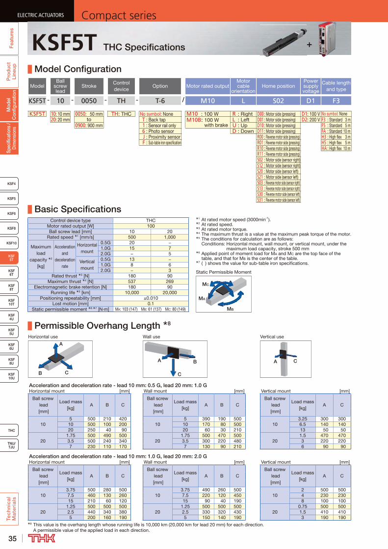
35
ELECTRIC ACTUATORS Compact seriesP
rod
uct
Line
upTe
ch
nic
al
Ma
teri
als
KSF4
KSF 10T
KSF10
KSF 6T
KSF 8T
KSF 10U
KSF 4U
KSF 5U
KSF 6U
KSF 8U
TNU/TJU
THC
Spec
ifica
tions
/ D
imen
sion
sM
odel
C
onfig
urat
ion
Fea
ture
sELECTRIC ACTUATORS Compact series
KSF5
KSF6
ELECTRIC ACTUATORS Compact series
KSF 5T
KSF8
ELECTRIC ACTUATORS Compact series
KSF5T THC Specifications
Model Configuration
ModelBall
screw lead
StrokeControl device
Option Motor rated outputMotor cable
orientationHome position
Power supply voltage
Cable length and type
KSF5T - 10 - 0050 - TH - T-6 / M10 L S02 D1 F3
KSF5T 10: 10 mm 0050: 50 mm TH: THC No symbol: None M10 : 100 W R : Right D00 : Motor side (pressing) D1: 100 V No symbol: None20: 20 mm to T : Back tap M10B: 100 W
with brakeL : Left D01 : Motor side (pressing) D2: 200 V F3 : Standard 3 m
0900: 900 mm 1 : Sensor rail only U : Up D10 : Motor side (pressing) F5 : Standard 5 m 6 : Photo sensor D : Down D11 : Motor side (pressing) FA : Standard 10 m J : Proximity sensor R00 : Reverse motor side (pressing) H3 : High flex 3 m F : Sub-table iron specification R01 : Reverse motor side (pressing) H5 : High flex 5 m
R10 : Reverse motor side (pressing) HA : High flex 10 mR11 : Reverse motor side (pressing)S02 : Motor side (sensor right)S12 : Motor side (sensor right)S20 : Motor side (sensor left)S21 : Motor side (sensor left)S03 : Reverse motor side (sensor right)S13 : Reverse motor side (sensor right)S30 : Reverse motor side (sensor left)S31 : Reverse motor side (sensor left)
Basic SpecificationsControl device type THC
Motor rated output [W] 100Ball screw lead [mm] 10 20
Rated speed 1 [mm/s] 500 1,000
Maximum load
capacity 2 [kg]
Acceleration and
deceleration rate
Horizontal mount
0.5G 20 −1.0G 15 72.0G − 5
Vertical mount
0.5G 13 −1.0G 8 62.0G − 3
Rated thrust 3 [N] 180 90Maximum thrust 4 [N] 537 269
Electromagnetic brake retention [N] 180 90Running life 5 [km] 10,000 20,000
Positioning repeatability [mm] ±0.010Lost motion [mm] 0.1
Static permissible moment 6 7 [N·m] MA: 103 (147) MB: 61 (137) MC: 80 (149)
Permissible Overhang Length 8
Horizontal use Wall use Vertical use
CB
A
A B
C
A C
Acceleration and deceleration rate - lead 10 mm: 0.5 G, lead 20 mm: 1.0 GHorizontal mount [mm] Wall mount [mm] Vertical mount [mm]
Ball screw lead [mm]
Load mass [kg]
A B CBall screw
lead [mm]
Load mass [kg]
A B CBall screw
lead [mm]
Load mass [kg]
A C
105 500 210 420
105 390 190 500
103.25 300 300
10 500 100 200 10 170 80 500 6.5 140 14020 250 40 90 20 60 30 210 13 50 50
201.75 500 490 500
201.75 500 470 500
201.5 470 470
3.5 500 240 340 3.5 300 220 480 3 220 2207 230 110 170 7 130 90 210 6 90 90
Acceleration and deceleration rate - lead 10 mm: 1.0 G, lead 20 mm: 2.0 GHorizontal mount [mm] Wall mount [mm] Vertical mount [mm]
Ball screw lead [mm]
Load mass [kg]
A B CBall screw
lead [mm]
Load mass [kg]
A B CBall screw
lead [mm]
Load mass [kg]
A C
103.75 500 280 500
103.75 490 260 500
102 500 500
7.5 460 130 260 7.5 220 120 450 4 230 23015 210 60 120 15 90 40 190 8 100 100
201.25 500 500 500
201.25 500 500 500
200.75 500 500
2.5 440 340 380 2.5 330 320 430 1.5 410 4105 200 160 190 5 150 140 190 3 190 190
8 This value is the overhang length whose running life is 10,000 km (20,000 km for lead 20 mm) for each direction. A permissible value of the applied load in each direction.
MB
MA
MC
Static Permissible Moment
1 At rated motor speed (3000min-1).2 At rated speed.3 At rated motor torque.4 The maximum thrust is a value at the maximum peak torque of the motor.5 The conditions for calculation are as follows:
Conditions: Horizontal mount, wall mount, or vertical mount, under the maximum load capacity, stroke 500 mm
6 Applied point of moment load for MA and MC are the top face of the table, and that for MB is the center of the table.
7 ( ) shows the value for sub-table iron specifications.
+
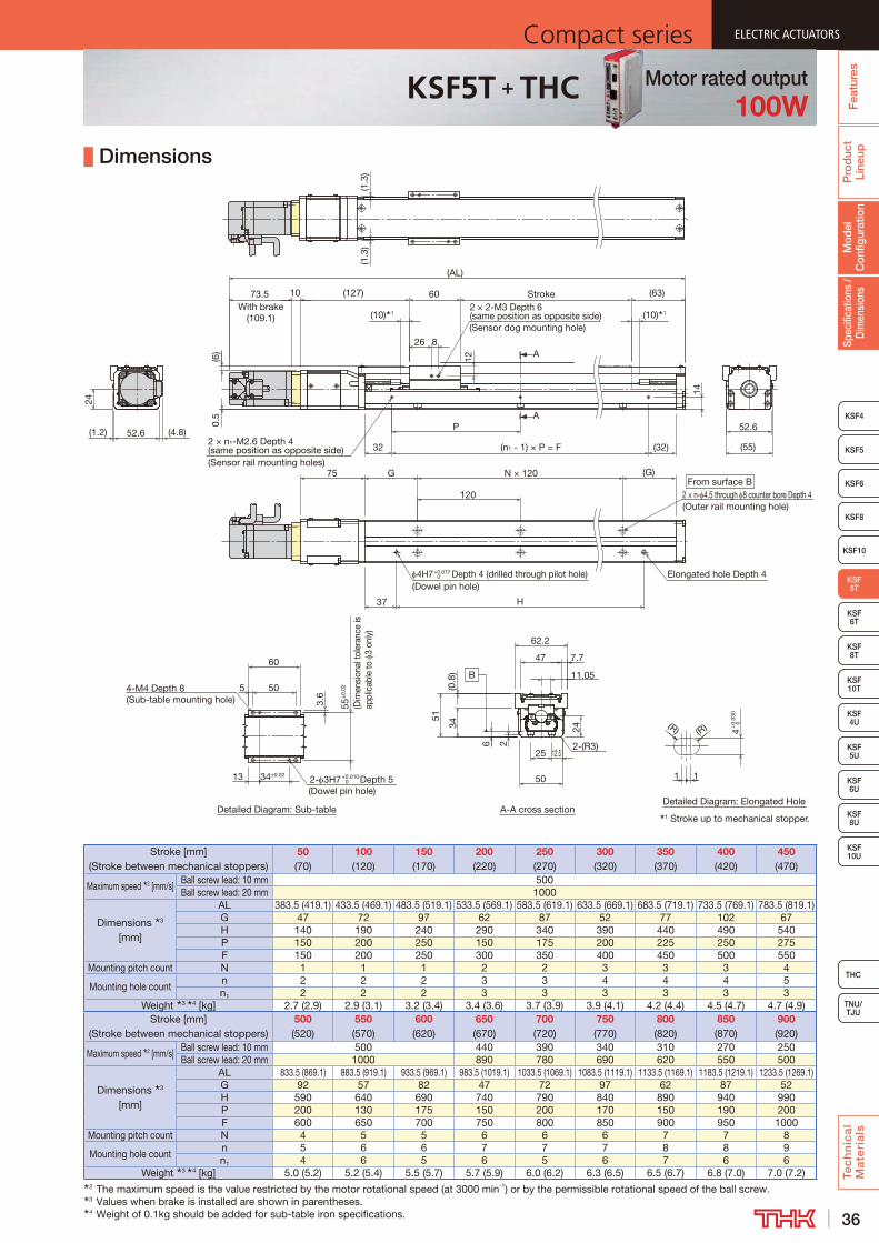
36
ELECTRIC ACTUATORSCompact series
Pro
duc
t Li
neup
Tec
hn
ica
l M
ate
ria
ls
THC
TNU/TJU
KSF4
KSF 10T
KSF10
KSF 6T
KSF 8T
KSF 10U
KSF 4U
KSF 5U
KSF 6U
KSF 8U
Spec
ifica
tions
/ D
imen
sion
sM
odel
C
onfig
urat
ion
Fea
ture
s
ELECTRIC ACTUATORSCompact series
KSF5
KSF6
ELECTRIC ACTUATORSCompact series
KSF 5T
KSF8
ELECTRIC ACTUATORSCompact series
KSF5T + THC Motor rated output100W
Dimensions
Stroke [mm] (Stroke between mechanical stoppers)
50 (70)
100 (120)
150 (170)
200 (220)
250 (270)
300 (320)
350 (370)
400 (420)
450 (470)
Maximum speed 2 [mm/s]Ball screw lead: 10 mm 500Ball screw lead: 20 mm 1000
Dimensions 3 [mm]
AL 383.5 (419.1) 433.5 (469.1) 483.5 (519.1) 533.5 (569.1) 583.5 (619.1) 633.5 (669.1) 683.5 (719.1) 733.5 (769.1) 783.5 (819.1)G 47 72 97 62 87 52 77 102 67H 140 190 240 290 340 390 440 490 540P 150 200 250 150 175 200 225 250 275F 150 200 250 300 350 400 450 500 550
Mounting pitch count N 1 1 1 2 2 3 3 3 4
Mounting hole countn 2 2 2 3 3 4 4 4 5n1 2 2 2 3 3 3 3 3 3
Weight 3 4 [kg] 2.7 (2.9) 2.9 (3.1) 3.2 (3.4) 3.4 (3.6) 3.7 (3.9) 3.9 (4.1) 4.2 (4.4) 4.5 (4.7) 4.7 (4.9)Stroke [mm]
(Stroke between mechanical stoppers)500 (520)
550 (570)
600 (620)
650 (670)
700 (720)
750 (770)
800 (820)
850 (870)
900 (920)
Maximum speed 2 [mm/s]Ball screw lead: 10 mm 500 440 390 340 310 270 250Ball screw lead: 20 mm 1000 890 780 690 620 550 500
Dimensions 3 [mm]
AL 833.5 (869.1) 883.5 (919.1) 933.5 (969.1) 983.5 (1019.1) 1033.5 (1069.1) 1083.5 (1119.1) 1133.5 (1169.1) 1183.5 (1219.1) 1233.5 (1269.1)G 92 57 82 47 72 97 62 87 52H 590 640 690 740 790 840 890 940 990P 200 130 175 150 200 170 150 190 200F 600 650 700 750 800 850 900 950 1000
Mounting pitch count N 4 5 5 6 6 6 7 7 8
Mounting hole countn 5 6 6 7 7 7 8 8 9n1 4 6 5 6 5 6 7 6 6
Weight 3 4 [kg] 5.0 (5.2) 5.2 (5.4) 5.5 (5.7) 5.7 (5.9) 6.0 (6.2) 6.3 (6.5) 6.5 (6.7) 6.8 (7.0) 7.0 (7.2)2 The maximum speed is the value restricted by the motor rotational speed (at 3000 min-1) or by the permissible rotational speed of the ball screw.3 Values when brake is installed are shown in parentheses.4 Weight of 0.1kg should be added for sub-table iron specifications.
14
1 Stroke up to mechanical stopper.
Detailed Diagram: Elongated HoleA-A cross sectionDetailed Diagram: Sub-table
A
A
B
60
(1.3
)
(63)Stroke(127)
(1.3
)
52.6
1073.5With brake
(109.1)
(AL)
24
(R) (R)
1
4+
0.03
0 0
1
5
55±
0.0250
3.6
4-M4 Depth 8(Sub-table mounting hole)
60
34±0.0213 2- 3H7+0.010 0 Depth 5
(Dowel pin hole)
2-(R3)
24
(0.8
)
6
50
2
34
62.2
12.525
47
11.05
51
7.7
2 × 2-M3 Depth 6 (same position as opposite side)(Sensor dog mounting hole)
8
12
26
0.5
(G)
H
G
120
N × 120
37
Elongated hole Depth 4
From surface B2 × n- 4.5 through 8 counter bore Depth 4(Outer rail mounting hole)
4H7+0.012 0 Depth 4 (drilled through pilot hole)
(Dowel pin hole)
75
2 × n1-M2.6 Depth 4 (same position as opposite side)(Sensor rail mounting holes)
(32)
P
32
(4.8)(1.2)
(55)
52.6
(6)
(n1 - 1) × P = F
(10) 1(10) 1
(Dim
ensi
onal
tole
ranc
e is
ap
plic
able
to
3 on
ly)
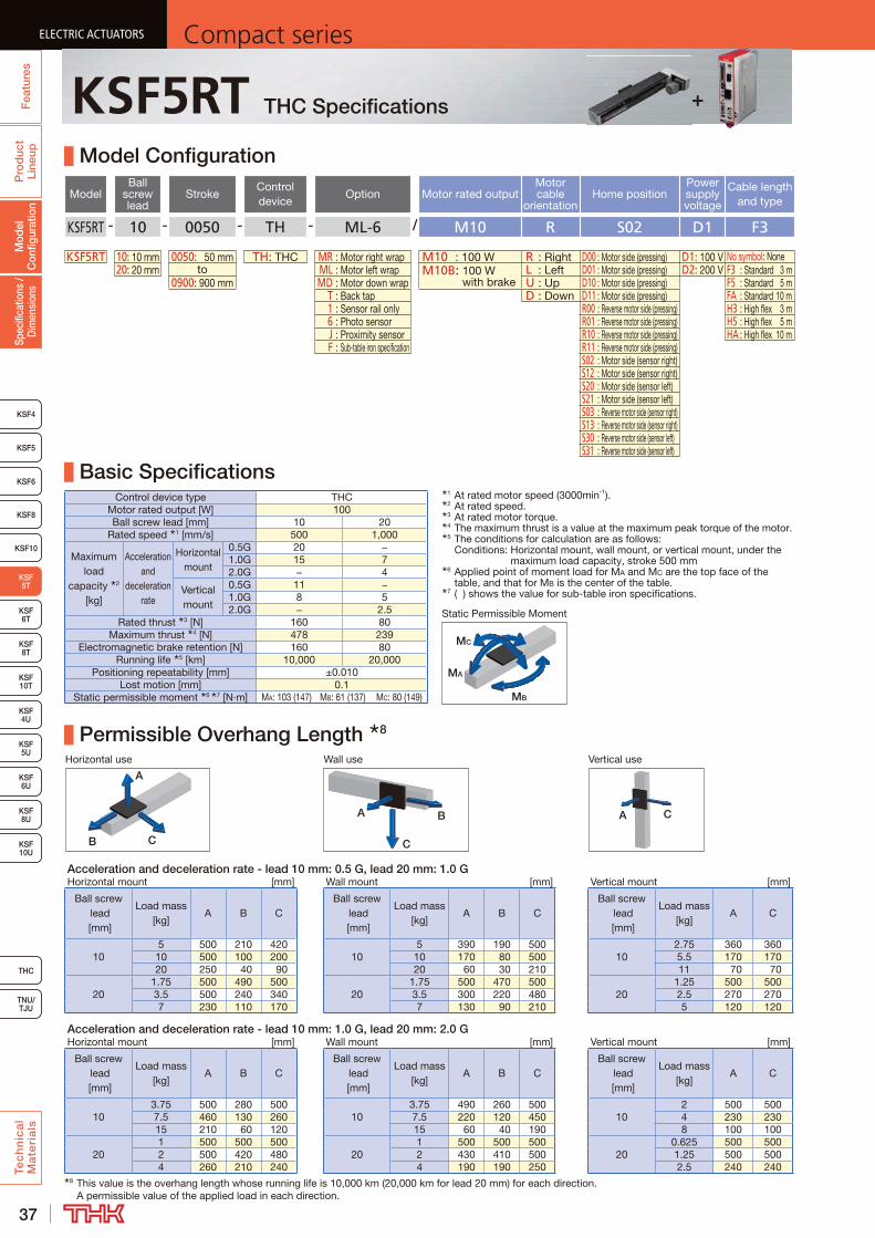
37
ELECTRIC ACTUATORS Compact seriesP
rod
uct
Line
upTe
ch
nic
al
Ma
teri
als
KSF4
KSF 10T
KSF10
KSF 6T
KSF 8T
KSF 10U
KSF 4U
KSF 5U
KSF 6U
KSF 8U
TNU/TJU
THC
Spec
ifica
tions
/ D
imen
sion
sM
odel
C
onfig
urat
ion
Fea
ture
sELECTRIC ACTUATORS Compact series
KSF5
KSF6
ELECTRIC ACTUATORS Compact series
KSF 5T
KSF8
ELECTRIC ACTUATORS Compact series
KSF5RT THC Specifications
Model Configuration
ModelBall
screw lead
StrokeControl device
Option Motor rated outputMotor cable
orientationHome position
Power supply voltage
Cable length and type
KSF5RT - 10 - 0050 - TH - ML-6 / M10 R S02 D1 F3
KSF5RT 10: 10 mm 0050: 50 mm TH: THC MR : Motor right wrap M10 : 100 W R : Right D00 : Motor side (pressing) D1: 100 V No symbol: None20: 20 mm to ML : Motor left wrap M10B: 100 W
with brakeL : Left D01 : Motor side (pressing) D2: 200 V F3 : Standard 3 m
0900: 900 mm MD : Motor down wrap U : Up D10 : Motor side (pressing) F5 : Standard 5 m T : Back tap D : Down D11 : Motor side (pressing) FA : Standard 10 m 1 : Sensor rail only R00 : Reverse motor side (pressing) H3 : High flex 3 m 6 : Photo sensor R01 : Reverse motor side (pressing) H5 : High flex 5 m J : Proximity sensor R10 : Reverse motor side (pressing) HA : High flex 10 m F : Sub-table iron specification R11 : Reverse motor side (pressing)
S02 : Motor side (sensor right)S12 : Motor side (sensor right)S20 : Motor side (sensor left)S21 : Motor side (sensor left)S03 : Reverse motor side (sensor right)S13 : Reverse motor side (sensor right)S30 : Reverse motor side (sensor left)S31 : Reverse motor side (sensor left)
Basic SpecificationsControl device type THC
Motor rated output [W] 100Ball screw lead [mm] 10 20
Rated speed 1 [mm/s] 500 1,000
Maximum load
capacity 2 [kg]
Acceleration and
deceleration rate
Horizontal mount
0.5G 20 −1.0G 15 72.0G − 4
Vertical mount
0.5G 11 −1.0G 8 52.0G − 2.5
Rated thrust 3 [N] 160 80Maximum thrust 4 [N] 478 239
Electromagnetic brake retention [N] 160 80Running life 5 [km] 10,000 20,000
Positioning repeatability [mm] ±0.010Lost motion [mm] 0.1
Static permissible moment 6 7 [N·m] MA: 103 (147) MB: 61 (137) MC: 80 (149)
Permissible Overhang Length 8
Horizontal use Wall use Vertical use
CB
A
A B
C
A C
Acceleration and deceleration rate - lead 10 mm: 0.5 G, lead 20 mm: 1.0 GHorizontal mount [mm] Wall mount [mm] Vertical mount [mm]
Ball screw lead [mm]
Load mass [kg]
A B CBall screw
lead [mm]
Load mass [kg]
A B CBall screw
lead [mm]
Load mass [kg]
A C
105 500 210 420
105 390 190 500
102.75 360 360
10 500 100 200 10 170 80 500 5.5 170 17020 250 40 90 20 60 30 210 11 70 70
201.75 500 490 500
201.75 500 470 500
201.25 500 500
3.5 500 240 340 3.5 300 220 480 2.5 270 2707 230 110 170 7 130 90 210 5 120 120
Acceleration and deceleration rate - lead 10 mm: 1.0 G, lead 20 mm: 2.0 GHorizontal mount [mm] Wall mount [mm] Vertical mount [mm]
Ball screw lead [mm]
Load mass [kg]
A B CBall screw
lead [mm]
Load mass [kg]
A B CBall screw
lead [mm]
Load mass [kg]
A C
103.75 500 280 500
103.75 490 260 500
102 500 500
7.5 460 130 260 7.5 220 120 450 4 230 23015 210 60 120 15 60 40 190 8 100 100
201 500 500 500
201 500 500 500
200.625 500 500
2 500 420 480 2 430 410 500 1.25 500 5004 260 210 240 4 190 190 250 2.5 240 240
8 This value is the overhang length whose running life is 10,000 km (20,000 km for lead 20 mm) for each direction. A permissible value of the applied load in each direction.
MB
MA
MC
Static Permissible Moment
1 At rated motor speed (3000min-1).2 At rated speed.3 At rated motor torque.4 The maximum thrust is a value at the maximum peak torque of the motor.5 The conditions for calculation are as follows:
Conditions: Horizontal mount, wall mount, or vertical mount, under the maximum load capacity, stroke 500 mm
6 Applied point of moment load for MA and MC are the top face of the table, and that for MB is the center of the table.
7 ( ) shows the value for sub-table iron specifications.
+
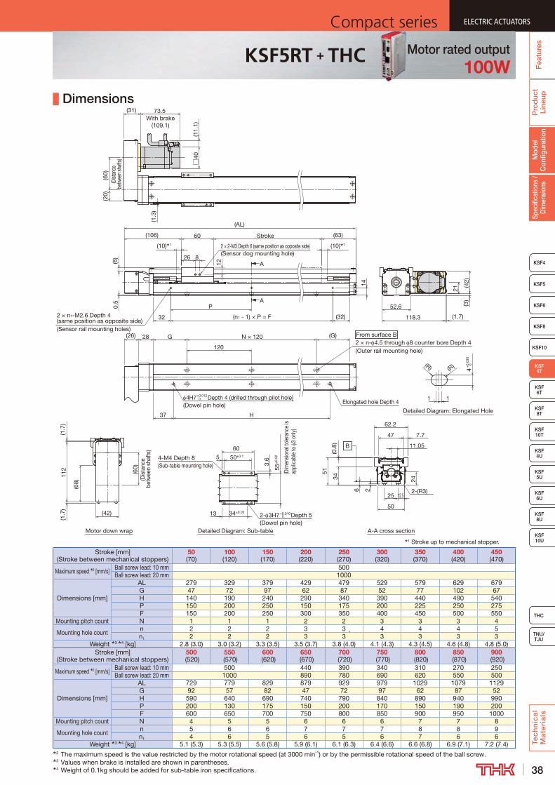
38
ELECTRIC ACTUATORSCompact series
Pro
duc
t Li
neup
Tec
hn
ica
l M
ate
ria
ls
THC
TNU/TJU
KSF4
KSF 10T
KSF10
KSF 6T
KSF 8T
KSF 10U
KSF 4U
KSF 5U
KSF 6U
KSF 8U
Spec
ifica
tions
/ D
imen
sion
sM
odel
C
onfig
urat
ion
Fea
ture
s
ELECTRIC ACTUATORSCompact series
KSF5
KSF6
ELECTRIC ACTUATORSCompact series
KSF 5T
KSF8
ELECTRIC ACTUATORSCompact series
KSF5RT + THC Motor rated output100W
Dimensions
Stroke [mm] (Stroke between mechanical stoppers)
50 (70)
100 (120)
150 (170)
200 (220)
250 (270)
300 (320)
350 (370)
400 (420)
450 (470)
Maximum speed 2 [mm/s]Ball screw lead: 10 mm 500Ball screw lead: 20 mm 1000
Dimensions [mm]
AL 279 329 379 429 479 529 579 629 679G 47 72 97 62 87 52 77 102 67H 140 190 240 290 340 390 440 490 540P 150 200 250 150 175 200 225 250 275F 150 200 250 300 350 400 450 500 550
Mounting pitch count N 1 1 1 2 2 3 3 3 4
Mounting hole countn 2 2 2 3 3 4 4 4 5n1 2 2 2 3 3 3 3 3 3
Weight 3 4 [kg] 2.8 (3.0) 3.0 (3.2) 3.3 (3.5) 3.5 (3.7) 3.8 (4.0) 4.1 (4.3) 4.3 (4.5) 4.6 (4.8) 4.8 (5.0)Stroke [mm]
(Stroke between mechanical stoppers)500
(520)550
(570)600
(620)650
(670)700
(720)750
(770)800
(820)850
(870)900
(920)
Maximum speed 2 [mm/s]Ball screw lead: 10 mm 500 440 390 340 310 270 250Ball screw lead: 20 mm 1000 890 780 690 620 550 500
Dimensions [mm]
AL 729 779 829 879 929 979 1029 1079 1129G 92 57 82 47 72 97 62 87 52H 590 640 690 740 790 840 890 940 990P 200 130 175 150 200 170 150 190 200F 600 650 700 750 800 850 900 950 1000
Mounting pitch count N 4 5 5 6 6 6 7 7 8
Mounting hole countn 5 6 6 7 7 7 8 8 9n1 4 6 5 6 5 6 7 6 6
Weight 3 4 [kg] 5.1 (5.3) 5.3 (5.5) 5.6 (5.8) 5.9 (6.1) 6.1 (6.3) 6.4 (6.6) 6.6 (6.8) 6.9 (7.1) 7.2 (7.4)2 The maximum speed is the value restricted by the motor rotational speed (at 3000 min-1) or by the permissible rotational speed of the ball screw.3 Values when brake is installed are shown in parentheses.4 Weight of 0.1kg should be added for sub-table iron specifications.
12
1 Stroke up to mechanical stopper.
Motor down wrap
Detailed Diagram: Elongated Hole
Detailed Diagram: Sub-table
A
A
A-A cross section
B
(R) (R)
1
4+
0.03
0 0
1
60
(31) 73.5With brake
(109.1)
(63)Stroke
(10) 1(10) 1
5
55±
0.02
(Dim
ensio
nal t
oler
ance
is
appl
icab
le to
3
only)
50±0.1
3.64-M4 Depth 8
(Sub-table mounting hole)
60
(1.3
)
37
N × 120
120
G
H
(G)
Elongated hole Depth 4
From surface B2 × n- 4.5 through 8 counter bore Depth 4(Outer rail mounting hole)
4H7+0.012 0 Depth 4 (drilled through pilot hole)
(Dowel pin hole)
32
P
(32)(n1 - 1) × P = F2 × n1-M2.6 Depth 4 (same position as opposite side)(Sensor rail mounting holes)
(26) 28
(106)
(AL)
52.6
(1.7
)
(1.7)
(3)
(42)
118.3
21
□40
(11.
1)
(60)
(Dist
ance
be
twee
n sh
afts)
(20)
112
(1.7
)
(42)
(68)
(60)
(Dis
tanc
e be
twee
n sh
afts
)
26 8
2 × 2-M3 Depth 6 (same position as opposite side)(Sensor dog mounting hole)
0.5
(6)
34±0.0213 2- 3H7+0.010 0 Depth 5
(Dowel pin hole)
12.5
50
2
7.7
51
6
62.2
11.05
47
25
34 24
2-(R3)
(0.8
)
14
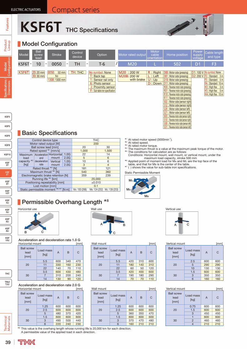
39
ELECTRIC ACTUATORS Compact seriesP
rod
uct
Line
upTe
ch
nic
al
Ma
teri
als
KSF8
KSF4
KSF 10T
KSF10
KSF 5T
KSF 8T
KSF 10U
KSF 4U
KSF 5U
KSF 6U
KSF 8U
TNU/TJU
THC
Spec
ifica
tions
/ D
imen
sion
sM
odel
C
onfig
urat
ion
Fea
ture
sELECTRIC ACTUATORS Compact series
KSF5
KSF6
ELECTRIC ACTUATORS Compact series
KSF 6T
ELECTRIC ACTUATORS Compact series
KSF6T THC Specifications
Model Configuration
ModelBall
screw lead
StrokeControl device
Option Motor rated outputMotor cable
orientationHome position
Power supply voltage
Cable length and type
KSF6T - 10 - 0050 - TH - T-6 / M20 L S02 D1 F3
KSF6T 20: 20 mm 0050: 50 mm TH: THC No symbol: None M20 : 200 W R : Right D00 : Motor side (pressing) D1: 100 V No symbol: None30: 30 mm to T : Back tap M20B: 200 W
with brakeL : Left D01 : Motor side (pressing) D2: 200 V F3 : Standard 3 m
1300: 1300 mm 1 : Sensor rail only U : Up D10 : Motor side (pressing) F5 : Standard 5 m 6 : Photo sensor D : Down D11 : Motor side (pressing) FA : Standard 10 m J : Proximity sensor R00 : Reverse motor side (pressing) H3 : High flex 3 m F : Sub-table iron specification R01 : Reverse motor side (pressing) H5 : High flex 5 m
R10 : Reverse motor side (pressing) HA : High flex 10 mR11 : Reverse motor side (pressing)S02 : Motor side (sensor right)S12 : Motor side (sensor right)S20 : Motor side (sensor left)S21 : Motor side (sensor left)S03 : Reverse motor side (sensor right)S13 : Reverse motor side (sensor right)S30 : Reverse motor side (sensor left)S31 : Reverse motor side (sensor left)
Basic SpecificationsControl device type THC
Motor rated output [W] 200Ball screw lead [mm] 20 30
Rated speed 1 [mm/s] 1,000 1,500Maximum
load capacity 2
[kg]
Acceleration and
deceleration rate
Horizontal mount
1.0G 22 142.0G 5 6
Vertical mount
1.0G 10 62.0G 3 4
Rated thrust 3 [N] 181 121Maximum thrust 4 [N] 540 360
Electromagnetic brake retention [N] 359 239Running life 5 [km] 20,000
Positioning repeatability [mm] ±0.010Lost motion [mm] 0.1
Static permissible moment 6 7 [N·m] MA: 150 (266) MB: 124 (252) MC: 139 (253)
Permissible Overhang Length 8
Horizontal use Wall use Vertical use
CB
A
A B
C
A C
Acceleration and deceleration rate 1.0 GHorizontal mount [mm] Wall mount [mm] Vertical mount [mm]
Ball screw lead [mm]
Load mass [kg]
A B CBall screw
lead [mm]
Load mass [kg]
A B CBall screw
lead [mm]
Load mass [kg]
A C
205.5 600 340 470
205.5 420 310 600
202.5 600 600
11 330 160 230 11 180 140 310 5 290 29022 140 70 110 22 60 50 120 10 130 130
303.5 600 430 480
303.5 420 400 600
301.5 600 600
7 310 200 240 7 190 180 290 3 350 35014 130 90 120 14 70 70 110 6 160 160
Acceleration and deceleration rate 2.0 GHorizontal mount [mm] Wall mount [mm] Vertical mount [mm]
Ball screw lead [mm]
Load mass [kg]
A B CBall screw
lead [mm]
Load mass [kg]
A B CBall screw
lead [mm]
Load mass [kg]
A C
201.25 600 600 600
201.25 600 600 600
200.75 600 600
2.5 600 600 600 2.5 600 600 600 1.5 600 6005 480 370 420 5 360 350 470 3 450 450
301.5 600 600 600
301.5 600 600 600
301 600 600
3 490 500 440 3 370 470 480 2 460 4606 220 240 230 6 160 210 210 4 210 210
8 This value is the overhang length whose running life is 20,000 km for each direction. A permissible value of the applied load in each direction.
MB
MA
MC
Static Permissible Moment
1 At rated motor speed (3000min-1).2 At rated speed.3 At rated motor torque.4 The maximum thrust is a value at the maximum peak torque of the motor.5 The conditions for calculation are as follows:
Conditions: Horizontal mount, wall mount, or vertical mount, under the maximum load capacity, stroke 500 mm
6 Applied point of moment load for MA and MC are the top face of the table, and that for MB is the center of the table.
7 ( ) shows the value for sub-table iron specifications.
+
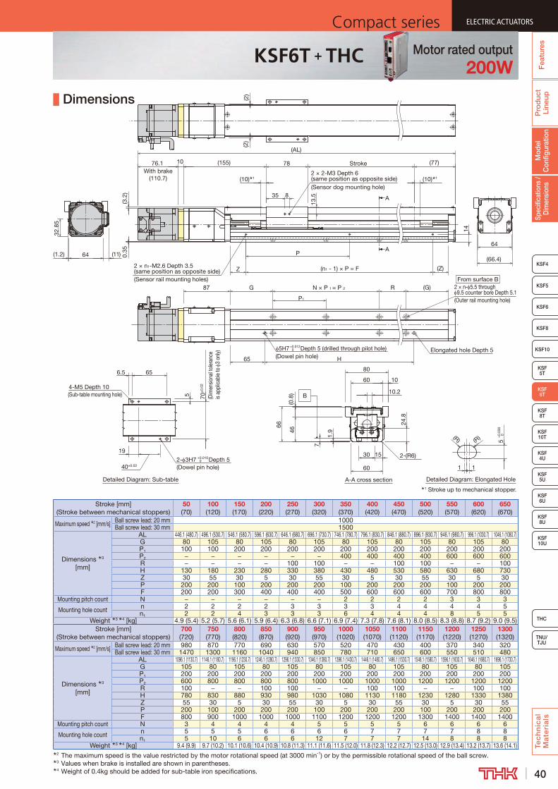
40
ELECTRIC ACTUATORSCompact series
Pro
duc
t Li
neup
Tec
hn
ica
l M
ate
ria
ls
THC
TNU/TJU
KSF8
KSF4
KSF 10T
KSF10
KSF 5T
KSF 8T
KSF 10U
KSF 4U
KSF 5U
KSF 6U
KSF 8U
Spec
ifica
tions
/ D
imen
sion
sM
odel
C
onfig
urat
ion
Fea
ture
s
ELECTRIC ACTUATORSCompact series
KSF5
KSF6
ELECTRIC ACTUATORSCompact series
KSF 6T
ELECTRIC ACTUATORSCompact series
KSF6T + THC Motor rated output200W
Dimensions
Stroke [mm] (Stroke between mechanical stoppers)
50 (70)
100 (120)
150 (170)
200 (220)
250 (270)
300 (320)
350 (370)
400 (420)
450 (470)
500 (520)
550 (570)
600 (620)
650 (670)
Maximum speed 2 [mm/s] Ball screw lead: 20 mm 1000Ball screw lead: 30 mm 1500
Dimensions 3 [mm]
AL 446.1 (480.7) 496.1 (530.7) 546.1 (580.7) 596.1 (630.7) 646.1 (680.7) 696.1 (730.7) 746.1 (780.7) 796.1 (830.7) 846.1 (880.7) 896.1 (930.7) 946.1 (980.7) 996.1 (1030.7) 1046.1 (1080.7)G 80 105 80 105 80 105 80 105 80 105 80 105 80P1 100 100 200 200 200 200 200 200 200 200 200 200 200P2 − − − − − − 400 400 400 400 600 600 600R − − − − 100 100 − − 100 100 − − 100H 130 180 230 280 330 380 430 480 530 580 630 680 730Z 30 55 30 5 30 55 30 5 30 55 30 5 30P 200 200 100 200 200 200 100 200 200 200 100 200 200F 200 200 300 400 400 400 500 600 600 600 700 800 800
Mounting pitch count N − − − − − − 2 2 2 2 3 3 3
Mounting hole count n 2 2 2 2 3 3 3 3 4 4 4 4 5n1 2 2 4 3 3 3 6 4 4 4 8 5 5
Weight 3 4 [kg] 4.9 (5.4) 5.2 (5.7) 5.6 (6.1) 5.9 (6.4) 6.3 (6.8) 6.6 (7.1) 6.9 (7.4) 7.3 (7.8) 7.6 (8.1) 8.0 (8.5) 8.3 (8.8) 8.7 (9.2) 9.0 (9.5)Stroke [mm]
(Stroke between mechanical stoppers)700 (720)
750 (770)
800 (820)
850 (870)
900 (920)
950 (970)
1000 (1020)
1050 (1070)
1100 (1120)
1150 (1170)
1200 (1220)
1250 (1270)
1300 (1320)
Maximum speed 2 [mm/s] Ball screw lead: 20 mm 980 870 770 690 630 570 520 470 430 400 370 340 320Ball screw lead: 30 mm 1470 1300 1160 1040 940 850 780 710 650 600 550 510 480
Dimensions 3 [mm]
AL 1096.1 (1130.7) 1146.1 (1180.7) 1196.1 (1230.7) 1246.1 (1280.7) 1296.1 (1330.7) 1346.1 (1380.7) 1396.1 (1430.7) 1446.1 (1480.7) 1496.1 (1530.7) 1546.1 (1580.7) 1596.1 (1630.7) 1646.1 (1680.7) 1696.1 (1730.7)G 105 80 105 80 105 80 105 80 105 80 105 80 105P1 200 200 200 200 200 200 200 200 200 200 200 200 200P2 600 800 800 800 800 1000 1000 1000 1000 1200 1200 1200 1200R 100 − − 100 100 − − 100 100 − − 100 100H 780 830 880 930 980 1030 1080 1130 1180 1230 1280 1330 1380Z 55 30 5 30 55 30 5 30 55 30 5 30 55P 200 100 200 200 200 100 200 200 200 100 200 200 200F 800 900 1000 1000 1000 1100 1200 1200 1200 1300 1400 1400 1400
Mounting pitch count N 3 4 4 4 4 5 5 5 5 6 6 6 6
Mounting hole count n 5 5 5 6 6 6 6 7 7 7 7 8 8n1 5 10 6 6 6 12 7 7 7 14 8 8 8
Weight 3 4 [kg] 9.4 (9.9) 9.7 (10.2) 10.1 (10.6) 10.4 (10.9) 10.8 (11.3) 11.1 (11.6) 11.5 (12.0) 11.8 (12.3) 12.2 (12.7) 12.5 (13.0) 12.9 (13.4) 13.2 (13.7) 13.6 (14.1)2 The maximum speed is the value restricted by the motor rotational speed (at 3000 min-1) or by the permissible rotational speed of the ball screw.3 Values when brake is installed are shown in parentheses.4 Weight of 0.4kg should be added for sub-table iron specifications.
1 Stroke up to mechanical stopper.
A
A
Detailed Diagram: Elongated HoleDetailed Diagram: Sub-table A-A cross section
B
2-(R6)
66
60
30 15
60
80
46
7
1.9
(n1 - 1) × P = F
14
(Z)Z2 × n1-M2.6 Depth 3.5 (same position as opposite side)(Sensor rail mounting holes)
P
Elongated hole Depth 5
P1
G
H65
87
5H7+0.012 0 Depth 5 (drilled through pilot hole)
(Dowel pin hole)
(G)RN × P 1 = P 2
From surface B2 × n- 5.5 through 9.5 counter bore Depth 5.1
(Outer rail mounting hole)
(2)
(2)
24.8
10.2
78 Stroke (77)(155)
10
64
1076.1
(110.7)With brake
(AL)
1 1
5+
0.03
0 0
(R)(R)
32.8
5
5
19
6.5
4-M5 Depth 10(Sub-table mounting hole)
40±0.02
65
70±
0.02
(Dim
ensio
nal t
oler
ance
is
appl
icab
le to
3
only)
2- 3H7 +0.010 0 Depth 5
(Dowel pin hole)
8
2 × 2-M3 Depth 6 (same position as opposite side)(Sensor dog mounting hole)
35
0.35
(11)(1.2)
64
(66.4)
(0.8
)
(3.2
)
(10) 1 (10) 1
13.5
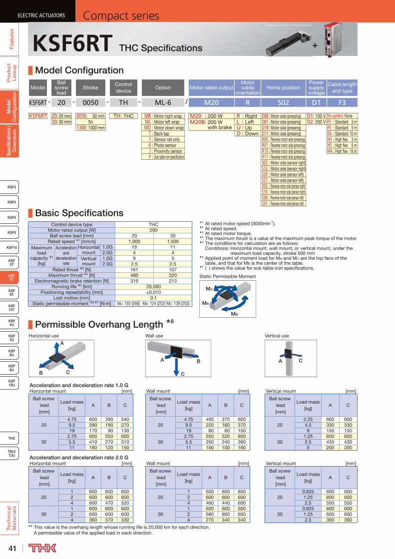
41
ELECTRIC ACTUATORS Compact seriesP
rod
uct
Line
upTe
ch
nic
al
Ma
teri
als
KSF8
KSF4
KSF 10T
KSF10
KSF 5T
KSF 8T
KSF 10U
KSF 4U
KSF 5U
KSF 6U
KSF 8U
TNU/TJU
THC
Spec
ifica
tions
/ D
imen
sion
sM
odel
C
onfig
urat
ion
Fea
ture
sELECTRIC ACTUATORS Compact series
KSF5
KSF6
ELECTRIC ACTUATORS Compact series
KSF 6T
ELECTRIC ACTUATORS Compact series
KSF6RT THC Specifications
Model Configuration
ModelBall
screw lead
StrokeControl device
Option Motor rated outputMotor cable
orientationHome position
Power supply voltage
Cable length and type
KSF6RT - 20 - 0050 - TH - ML-6 / M20 R S02 D1 F3
KSF6RT 20: 20 mm 0050: 50 mm TH: THC MR : Motor right wrap M20 : 200 W R : Right D00 : Motor side (pressing) D1: 100 V No symbol: None30: 30 mm to ML : Motor left wrap M20B: 200 W
with brakeL : Left D01 : Motor side (pressing) D2: 200 V F3 : Standard 3 m
1300: 1300 mm MD : Motor down wrap U : Up D10 : Motor side (pressing) F5 : Standard 5 m T : Back tap D : Down D11 : Motor side (pressing) FA : Standard 10 m 1 : Sensor rail only R00 : Reverse motor side (pressing) H3 : High flex 3 m 6 : Photo sensor R01 : Reverse motor side (pressing) H5 : High flex 5 m J : Proximity sensor R10 : Reverse motor side (pressing) HA : High flex 10 m F : Sub-table iron specification R11 : Reverse motor side (pressing)
S02 : Motor side (sensor right)S12 : Motor side (sensor right)S20 : Motor side (sensor left)S21 : Motor side (sensor left)S03 : Reverse motor side (sensor right)S13 : Reverse motor side (sensor right)S30 : Reverse motor side (sensor left)S31 : Reverse motor side (sensor left)
Basic SpecificationsControl device type THC
Motor rated output [W] 200Ball screw lead [mm] 20 30
Rated speed 1 [mm/s] 1,000 1,500Maximum
load capacity 2
[kg]
Acceleration and
deceleration rate
Horizontal mount
1.0G 19 112.0G 4 4
Vertical mount
1.0G 9 52.0G 2.5 2.5
Rated thrust 3 [N] 161 107Maximum thrust 4 [N] 480 320
Electromagnetic brake retention [N] 319 213Running life 5 [km] 20,000
Positioning repeatability [mm] ±0.010Lost motion [mm] 0.1
Static permissible moment 6 7 [N·m] MA: 150 (266) MB: 124 (252) MC: 139 (253)
Permissible Overhang Length 8
Horizontal use Wall use Vertical use
CB
A
A B
C
A C
Acceleration and deceleration rate 1.0 GHorizontal mount [mm] Wall mount [mm] Vertical mount [mm]
Ball screw lead [mm]
Load mass [kg]
A B CBall screw
lead [mm]
Load mass [kg]
A B CBall screw
lead [mm]
Load mass [kg]
A C
204.75 600 390 540
204.75 490 370 600
202.25 600 600
9.5 390 190 270 9.5 220 160 370 4.5 330 33019 170 90 130 19 80 60 150 9 150 150
302.75 600 550 600
302.75 550 520 600
301.25 600 600
5.5 410 270 310 5.5 250 240 390 2.5 430 43011 180 120 150 11 100 100 160 5 200 200
Acceleration and deceleration rate 2.0 GHorizontal mount [mm] Wall mount [mm] Vertical mount [mm]
Ball screw lead [mm]
Load mass [kg]
A B CBall screw
lead [mm]
Load mass [kg]
A B CBall screw
lead [mm]
Load mass [kg]
A C
201 600 600 600
201 600 600 600
200.625 600 600
2 600 600 600 2 600 600 600 1.25 600 6004 600 470 520 4 460 440 600 2.5 550 550
301 600 600 600
301 600 600 600
300.625 600 600
2 600 600 600 2 580 600 600 1.25 600 6004 360 370 330 4 270 340 340 2.5 360 360
8 This value is the overhang length whose running life is 20,000 km for each direction. A permissible value of the applied load in each direction.
MB
MA
MC
Static Permissible Moment
1 At rated motor speed (3000min-1).2 At rated speed.3 At rated motor torque.4 The maximum thrust is a value at the maximum peak torque of the motor.5 The conditions for calculation are as follows:
Conditions: Horizontal mount, wall mount, or vertical mount, under the maximum load capacity, stroke 500 mm
6 Applied point of moment load for MA and MC are the top face of the table, and that for MB is the center of the table.
7 ( ) shows the value for sub-table iron specifications.
+

42
ELECTRIC ACTUATORSCompact series
Pro
duc
t Li
neup
Tec
hn
ica
l M
ate
ria
ls
THC
TNU/TJU
KSF8
KSF4
KSF 10T
KSF10
KSF 5T
KSF 8T
KSF 10U
KSF 4U
KSF 5U
KSF 6U
KSF 8U
Spec
ifica
tions
/ D
imen
sion
sM
odel
C
onfig
urat
ion
Fea
ture
s
ELECTRIC ACTUATORSCompact series
KSF5
KSF6
ELECTRIC ACTUATORSCompact series
KSF 6T
ELECTRIC ACTUATORSCompact series
KSF6RT + THC Motor rated output200W
Dimensions
Stroke [mm] (Stroke between mechanical stoppers)
50 (70)
100 (120)
150 (170)
200 (220)
250 (270)
300 (320)
350 (370)
400 (420)
450 (470)
500 (520)
550 (570)
600 (620)
650 (670)
Maximum speed 2 [mm/s] Ball screw lead: 20 mm 1000Ball screw lead: 30 mm 1500
Dimensions [mm]
AL 336 386 436 486 536 586 636 686 736 786 836 886 936G 80 105 80 105 80 105 80 105 80 105 80 105 80P1 100 100 200 200 200 200 200 200 200 200 200 200 200P2 − − − − − − 400 400 400 400 600 600 600R − − − − 100 100 − − 100 100 − − 100H 130 180 230 280 330 380 430 480 530 580 630 680 730Z 30 55 30 5 30 55 30 5 30 55 30 5 30P 200 200 100 200 200 200 100 200 200 200 100 200 200F 200 200 300 400 400 400 500 600 600 600 700 800 800
Mounting pitch count N − − − − − − 2 2 2 2 3 3 3
Mounting hole count n 2 2 2 2 3 3 3 3 4 4 4 4 5n1 2 2 4 3 3 3 6 4 4 4 8 5 5
Weight 3 4 [kg] 5.3 (5.8) 5.7 (6.2) 6.0 (6.5) 6.4 (6.9) 6.7 (7.2) 7.1 (7.6) 7.4 (7.9) 7.8 (8.3) 8.1 (8.6) 8.5 (9.0) 8.8 (9.3) 9.2 (9.7) 9.5 (10.0)Stroke [mm]
(Stroke between mechanical stoppers)700 (720)
750 (770)
800 (820)
850 (870)
900 (920)
950 (970)
1000 (1020)
1050 (1070)
1100 (1120)
1150 (1170)
1200 (1220)
1250 (1270)
1300 (1320)
Maximum speed 2 [mm/s] Ball screw lead: 20 mm 980 870 770 690 630 570 520 470 430 400 370 340 320Ball screw lead: 30 mm 1470 1300 1160 1040 940 850 780 710 650 600 550 510 480
Dimensions [mm]
AL 986 1036 1086 1136 1186 1236 1286 1336 1386 1436 1486 1536 1586G 105 80 105 80 105 80 105 80 105 80 105 80 105P1 200 200 200 200 200 200 200 200 200 200 200 200 200P2 600 800 800 800 800 1000 1000 1000 1000 1200 1200 1200 1200R 100 − − 100 100 − − 100 100 − − 100 100H 780 830 880 930 980 1030 1080 1130 1180 1230 1280 1330 1380Z 55 30 5 30 55 30 5 30 55 30 5 30 55P 200 100 200 200 200 100 200 200 200 100 200 200 200F 800 900 1000 1000 1000 1100 1200 1200 1200 1300 1400 1400 1400
Mounting pitch count N 3 4 4 4 4 5 5 5 5 6 6 6 6
Mounting hole count n 5 5 5 6 6 6 6 7 7 7 7 8 8n1 5 10 6 6 6 12 7 7 7 14 8 8 8
Weight 3 4 [kg] 9.8 (10.3) 10.2 (10.7) 10.5 (11.0) 10.9 (11.4) 11.2 (11.7) 11.6 (12.1) 11.9 (12.4) 12.3 (12.8) 12.6 (13.1) 13.0 (13.5) 13.3 (13.8) 13.7 (14.2) 14.0 (14.5)2 The maximum speed is the value restricted by the motor rotational speed (at 3000 min-1) or by the permissible rotational speed of the ball screw.3 Values when brake is installed are shown in parentheses.4 Weight of 0.4kg should be added for sub-table iron specifications.
Motor down wrap1 Stroke up to mechanical stopper.
Detailed Diagram: Sub-table
A
A
Detailed Diagram: Elongated Hole
A-A cross section
B
8
14
78
(Z)
(131)
(10) 1(10) 1
Stroke (77)
P
Z
(Sensor rail mounting holes)
2 × n1-M2.6 Depth 3.5 (same position as opposite side)
76.1With brake
(110.7)
(2)
□60
(AL)
(n1 - 1) × P = F
0.35
(60)
64
148 (2)
(2.8
)
30
N × P 1 = P 2
1
(R)
5H7 + 0.012 Depth 5 (drilled through pilot hole)(Dowel pin hole)
0 1
5+
0.03
0 0
RFrom surface B2 × n- 5.5 through 9.5 counter bore Depth 5.1(Outer rail mounting hole)
G
H65
P1
Elongated hole Depth 5
(75)
(Dis
tanc
e b
etw
een
shaf
ts)
(60)
145
(83.
2)
(2)
(1.7
)
(G)
(R)
(40)
(13)
(75)
(Dist
ance
be
twee
n sha
fts)
(29)
2 × 2-M3 Depth 6 (same position as opposite side)(Sensor dog mounting hole)
35
5
19
6.5
4-M5 Depth 10(Sub-table mounting hole)
40±0.02
65
70±
0.02
(Dim
ensio
nal to
leran
ce is
ap
plica
ble to
3 on
ly)
2- 3H7 + 0.010 Depth 10(Dowel pin hole)
0
(3.1
5)
2-(R6)
66
60
30 15
60
80
46
7
1.9
24.8
10.2
10
(0.8
)
13.5
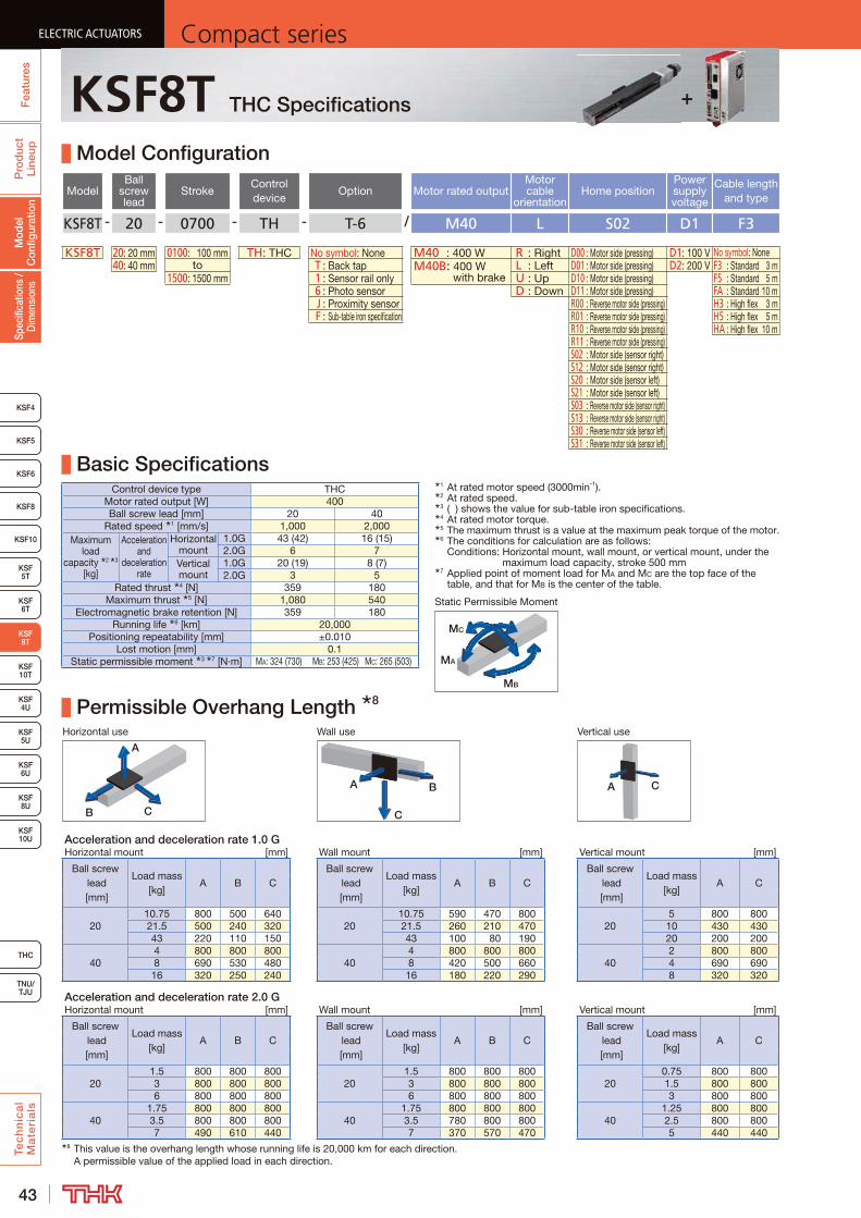
43
ELECTRIC ACTUATORS Compact seriesP
rod
uct
Line
upTe
ch
nic
al
Ma
teri
als
KSF8
KSF4
KSF 10T
KSF10
KSF 5T
KSF 6T
KSF 10U
KSF 5U
KSF 6U
KSF 8U
TNU/TJU
THC
Spec
ifica
tions
/ D
imen
sion
sM
odel
C
onfig
urat
ion
Fea
ture
sELECTRIC ACTUATORS Compact series
KSF5
KSF6
ELECTRIC ACTUATORS Compact series
KSF 8T
KSF 4U
ELECTRIC ACTUATORS Compact series
KSF8T THC Specifications
Model Configuration
ModelBall
screw lead
StrokeControl device
Option Motor rated outputMotor cable
orientationHome position
Power supply voltage
Cable length and type
KSF8T - 20 - 0700 - TH - T-6 / M40 L S02 D1 F3
KSF8T 20: 20 mm 0100: 100 mm TH: THC No symbol: None M40 : 400 W R : Right D00 : Motor side (pressing) D1: 100 V No symbol: None40: 40 mm to T : Back tap M40B: 400 W
with brakeL : Left D01 : Motor side (pressing) D2: 200 V F3 : Standard 3 m
1500: 1500 mm 1 : Sensor rail only U : Up D10 : Motor side (pressing) F5 : Standard 5 m 6 : Photo sensor D : Down D11 : Motor side (pressing) FA : Standard 10 m J : Proximity sensor R00 : Reverse motor side (pressing) H3 : High flex 3 m F : Sub-table iron specification R01 : Reverse motor side (pressing) H5 : High flex 5 m
R10 : Reverse motor side (pressing) HA : High flex 10 mR11 : Reverse motor side (pressing)S02 : Motor side (sensor right)S12 : Motor side (sensor right)S20 : Motor side (sensor left)S21 : Motor side (sensor left)S03 : Reverse motor side (sensor right)S13 : Reverse motor side (sensor right)S30 : Reverse motor side (sensor left)S31 : Reverse motor side (sensor left)
Basic SpecificationsControl device type THC
Motor rated output [W] 400Ball screw lead [mm] 20 40
Rated speed 1 [mm/s] 1,000 2,000Maximum
load capacity 2 3
[kg]
Acceleration and
deceleration rate
Horizontal mount
1.0G 43 (42) 16 (15)2.0G 6 7
Vertical mount
1.0G 20 (19) 8 (7)2.0G 3 5
Rated thrust 4 [N] 359 180Maximum thrust 5 [N] 1,080 540
Electromagnetic brake retention [N] 359 180Running life 6 [km] 20,000
Positioning repeatability [mm] ±0.010Lost motion [mm] 0.1
Static permissible moment 3 7 [N·m] MA: 324 (730) MB: 253 (425) MC: 265 (503)
Permissible Overhang Length 8
Horizontal use Wall use Vertical use
CB
A
A B
C
A C
Acceleration and deceleration rate 1.0 GHorizontal mount [mm] Wall mount [mm] Vertical mount [mm]
Ball screw lead [mm]
Load mass [kg]
A B CBall screw
lead [mm]
Load mass [kg]
A B CBall screw
lead [mm]
Load mass [kg]
A C
2010.75 800 500 640
2010.75 590 470 800
205 800 800
21.5 500 240 320 21.5 260 210 470 10 430 43043 220 110 150 43 100 80 190 20 200 200
404 800 800 800
404 800 800 800
402 800 800
8 690 530 480 8 420 500 660 4 690 69016 320 250 240 16 180 220 290 8 320 320
Acceleration and deceleration rate 2.0 GHorizontal mount [mm] Wall mount [mm] Vertical mount [mm]
Ball screw lead [mm]
Load mass [kg]
A B CBall screw
lead [mm]
Load mass [kg]
A B CBall screw
lead [mm]
Load mass [kg]
A C
201.5 800 800 800
201.5 800 800 800
200.75 800 800
3 800 800 800 3 800 800 800 1.5 800 8006 800 800 800 6 800 800 800 3 800 800
401.75 800 800 800
401.75 800 800 800
401.25 800 800
3.5 800 800 800 3.5 780 800 800 2.5 800 8007 490 610 440 7 370 570 470 5 440 440
8 This value is the overhang length whose running life is 20,000 km for each direction. A permissible value of the applied load in each direction.
MB
MA
MC
Static Permissible Moment
1 At rated motor speed (3000min-1).2 At rated speed.3 ( ) shows the value for sub-table iron specifications.4 At rated motor torque.5 The maximum thrust is a value at the maximum peak torque of the motor.6 The conditions for calculation are as follows:
Conditions: Horizontal mount, wall mount, or vertical mount, under the maximum load capacity, stroke 500 mm
7 Applied point of moment load for MA and MC are the top face of the table, and that for MB is the center of the table.
+

44
ELECTRIC ACTUATORSCompact series
Pro
duc
t Li
neup
Tec
hn
ica
l M
ate
ria
ls
THC
TNU/TJU
KSF8
KSF4
KSF 10T
KSF10
KSF 5T
KSF 6T
KSF 10U
KSF 5U
KSF 6U
KSF 8U
Spec
ifica
tions
/ D
imen
sion
sM
odel
C
onfig
urat
ion
Fea
ture
s
ELECTRIC ACTUATORSCompact series
KSF5
KSF6
ELECTRIC ACTUATORSCompact series
KSF 8T
KSF 4U
ELECTRIC ACTUATORSCompact series
KSF8T + THC Motor rated output400W
Dimensions
Stroke [mm] (Stroke between mechanical stoppers)
100 (120)
200 (220)
300 (320)
400 (420)
500 (520)
600 (620)
700 (720)
800 (820)
900 (920)
1000 (1020)
1100 (1120)
1200 (1220)
1300 (1320)
1400 (1420)
1500 (1520)
Maximum speed 2 [mm/s]
Ball screw lead: 20 mm 1000 970 790 660 550 470 410 360 320Ball screw lead: 40 mm 2000 1940 1580 1320 1110 950 830 720 640
Dimensions 3 [mm]
AL586.1 (620.7)
686.1 (720.7)
786.1 (820.7)
886.1 (920.7)
986.1 (1020.7)
1086.1 (1120.7)
1186.1 (1220.7)
1286.1 (1320.7)
1386.1 (1420.7)
1486.1 (1520.7)
1586.1 (1620.7)
1686.1 (1720.7)
1786.1 (1820.7)
1886.1 (1920.7)
1986.1 (2020.7)
G 85 135 85 135 85 135 85 135 85 135 85 135 85 135 85H 300 400 500 600 700 800 900 1000 1100 1200 1300 1400 1500 1600 1700Z 85 35 85 35 85 35 85 35 85 35 85 35 85 35 85F 200 400 400 600 600 800 800 1000 1000 1200 1200 1400 1400 1600 1600
Mounting pitch count N 1 1 2 2 3 3 4 4 5 5 6 6 7 7 8Mounting hole
countn 2 2 3 3 4 4 5 5 6 6 7 7 8 8 9n1 2 3 3 4 4 5 5 6 6 7 7 8 8 9 9
Weight 3 4 [kg]9.8
(10.3)11.0 (11.5)
12.3 (12.8)
13.5 (14.0)
14.8 (15.3)
16.0 (16.5)
17.3 (17.8)
18.5 (19.0)
19.8 (20.3)
21.1 (21.6)
22.3 (22.8)
23.6 (24.1)
24.8 (25.3)
26.1 (26.6)
27.3 (27.8)
2 The maximum speed is the value restricted by the motor rotational speed (at 3000 min-1) or by the permissible rotational speed of the ball screw.3 Values when brake is installed are shown in parentheses.4 Weight of 1.1kg should be added for sub-table iron specifications.
(10) 1
1 Stroke up to mechanical stopper.
A
A
B
(2)
Stroke (90)(168) 120
(2)
5H7 + 0.012 Depth 5 (drilled through pilot hole)0
(Dowel pin hole)
GFrom surface B2 × n- 6.6 through 11 counter bore Depth 6.3(Outer rail mounting hole)
N × 200
H
Elongated hole Depth 5
(R) (R) 5
+0.
030
0
93
35
200
(G)
11
84
10
(AL)
98.1
(132.7)With brake (10) 1
37
70±0.02
4-M6 Depth 12(Sub-table mounting hole)
25
4-M4 Depth 8 (From the back surface)(Sensor dog mounting hole) 2- 5H7 + 0.012 Depth 100
(Dowel pin hole)
100
50
92±
0.02
(Dim
ensio
nal t
oler
ance
is
appl
icabl
e to
5
only)
120
10
20
6
3.710
104
48
17
80
46
31.2
16
80
2-(R6)
12
80
(0.8
)
1
2 × n1-M2.6 Depth 3.5 (same position as opposite side)(Sensor rail mounting holes)
19
200
(n1 - 1) × P = F (Z)Z
84
(86.4)
(1)(1.2)
(13)
Detailed Diagram: Sub-table A-A cross section Detailed Diagram: Elongated Hole
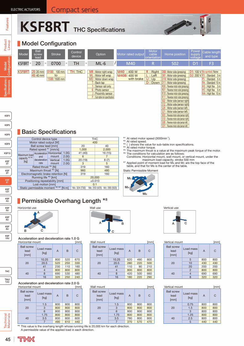
45
ELECTRIC ACTUATORS Compact seriesP
rod
uct
Line
upTe
ch
nic
al
Ma
teri
als
KSF8
KSF4
KSF 10T
KSF10
KSF 5T
KSF 6T
KSF 10U
KSF 5U
KSF 6U
KSF 8U
TNU/TJU
THC
Spec
ifica
tions
/ D
imen
sion
sM
odel
C
onfig
urat
ion
Fea
ture
sELECTRIC ACTUATORS Compact series
KSF5
KSF6
ELECTRIC ACTUATORS Compact series
KSF 8T
KSF 4U
ELECTRIC ACTUATORS Compact series
KSF8RT THC Specifications
Model Configuration
ModelBall
screw lead
StrokeControl device
Option Motor rated outputMotor cable
orientationHome position
Power supply voltage
Cable length and type
KSF8RT - 20 - 0700 - TH - ML-6 / M40 R S02 D1 F3
KSF8RT 20: 20 mm 0100: 100 mm TH: THC MR : Motor right wrap M40 : 400 W R : Right D00 : Motor side (pressing) D1: 100 V No symbol: None40: 40 mm to ML : Motor left wrap M40B: 400 W
with brakeL : Left D01 : Motor side (pressing) D2: 200 V F3 : Standard 3 m
1500: 1500 mm MD : Motor down wrap U : Up D10 : Motor side (pressing) F5 : Standard 5 m T : Back tap D : Down D11 : Motor side (pressing) FA : Standard 10 m 1 : Sensor rail only R00 : Reverse motor side (pressing) H3 : High flex 3 m 6 : Photo sensor R01 : Reverse motor side (pressing) H5 : High flex 5 m J : Proximity sensor R10 : Reverse motor side (pressing) HA : High flex 10 m F : Sub-table iron specification R11 : Reverse motor side (pressing)
S02 : Motor side (sensor right)S12 : Motor side (sensor right)S20 : Motor side (sensor left)S21 : Motor side (sensor left)S03 : Reverse motor side (sensor right)S13 : Reverse motor side (sensor right)S30 : Reverse motor side (sensor left)S31 : Reverse motor side (sensor left)
Basic SpecificationsControl device type THC
Motor rated output [W] 400Ball screw lead [mm] 20 40
Rated speed 1 [mm/s] 1,000 2,000
Maximum load capacity 2 3
[kg]
Acceleration and
deceleration rate
Horizontal mount
1.0G 41 (40) 16 (15)2.0G 6 7
Vertical mount
1.0G 20 (19) 8 (7)2.0G 3 5
Rated thrust 4 [N] 319 160Maximum thrust 5 [N] 960 480
Electromagnetic brake retention [N] 319 160Running life 6 [km] 20,000
Positioning repeatability [mm] ±0.010Lost motion [mm] 0.1
Static permissible moment 3 7 [N·m] MA: 324 (730) MB: 253 (425) MC: 265 (503)
Permissible Overhang Length 8
Horizontal use Wall use Vertical use
CB
A
A B
C
A C
Acceleration and deceleration rate 1.0 GHorizontal mount [mm] Wall mount [mm] Vertical mount [mm]
Ball screw lead [mm]
Load mass [kg]
A B CBall screw
lead [mm]
Load mass [kg]
A B CBall screw
lead [mm]
Load mass [kg]
A C
2010.25 800 520 670
2010.25 620 490 800
205 800 800
20.5 520 250 330 20.5 280 220 500 10 430 43041 230 110 160 41 110 90 210 20 200 200
404 800 800 800
404 800 800 800
402 800 800
8 690 530 480 8 420 500 660 4 690 69016 320 250 240 16 180 220 290 8 320 320
Acceleration and deceleration rate 2.0 GHorizontal mount [mm] Wall mount [mm] Vertical mount [mm]
Ball screw lead [mm]
Load mass [kg]
A B CBall screw
lead [mm]
Load mass [kg]
A B CBall screw
lead [mm]
Load mass [kg]
A C
201.5 800 800 800
201.5 800 800 800
200.75 800 800
3 800 800 800 3 800 800 800 1.5 800 8006 800 800 800 6 800 800 800 3 800 800
401.75 800 800 800
401.75 800 800 800
401.25 800 800
3.5 800 800 800 3.5 780 800 800 2.5 800 8007 490 610 440 7 370 570 470 5 440 440
8 This value is the overhang length whose running life is 20,000 km for each direction. A permissible value of the applied load in each direction.
MB
MA
MC
Static Permissible Moment
1 At rated motor speed (3000min-1).2 At rated speed.3 ( ) shows the value for sub-table iron specifications.4 At rated motor torque.5 The maximum thrust is a value at the maximum peak torque of the motor.6 The conditions for calculation are as follows:
Conditions: Horizontal mount, wall mount, or vertical mount, under the maximum load capacity, stroke 500 mm
7 Applied point of moment load for MA and MC are the top face of the table, and that for MB is the center of the table.
+
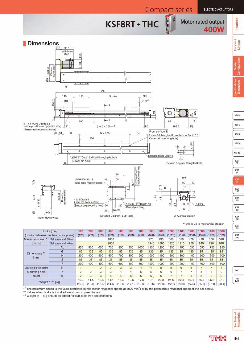
46
ELECTRIC ACTUATORSCompact series
Pro
duc
t Li
neup
Tec
hn
ica
l M
ate
ria
ls
THC
TNU/TJU
KSF8
KSF4
KSF 10T
KSF10
KSF 5T
KSF 6T
KSF 10U
KSF 5U
KSF 6U
KSF 8U
Spec
ifica
tions
/ D
imen
sion
sM
odel
C
onfig
urat
ion
Fea
ture
s
ELECTRIC ACTUATORSCompact series
KSF5
KSF6
ELECTRIC ACTUATORSCompact series
KSF 8T
KSF 4U
ELECTRIC ACTUATORSCompact series
KSF8RT + THC Motor rated output400W
Dimensions
Stroke [mm] (Stroke between mechanical stoppers)
100 (120)
200 (220)
300 (320)
400 (420)
500 (520)
600 (620)
700 (720)
800 (820)
900 (920)
1000 (1020)
1100 (1120)
1200 (1220)
1300 (1320)
1400 (1420)
1500 (1520)
Maximum speed 2 [mm/s]
Ball screw lead: 20 mm 1000 970 790 660 550 470 410 360 320Ball screw lead: 40 mm 2000 1940 1580 1320 1110 950 830 720 640
Dimensions 3 [mm]
AL 455 555 655 755 855 955 1055 1155 1255 1355 1455 1555 1655 1755 1855G 85 135 85 135 85 135 85 135 85 135 85 135 85 135 85H 300 400 500 600 700 800 900 1000 1100 1200 1300 1400 1500 1600 1700Z 85 35 85 35 85 35 85 35 85 35 85 35 85 35 85F 200 400 400 600 600 800 800 1000 1000 1200 1200 1400 1400 1600 1600
Mounting pitch count N 1 1 2 2 3 3 4 4 5 5 6 6 7 7 8Mounting hole
countn 2 2 3 3 4 4 5 5 6 6 7 7 8 8 9n1 2 3 3 4 4 5 5 6 6 7 7 8 8 9 9
Weight 3 4 [kg]10.3 (10.8)
11.5 (12.0)
12.8 (13.3)
14.1 (14.6)
15.3 (15.8)
16.6 (17.1)
17.8 (18.3)
19.1 (19.6)
20.3 (20.8)
21.6 (22.1)
22.8 (23.3)
24.1 (24.6)
25.3 (25.8)
26.6 (27.1)
27.9 (28.4)
2 The maximum speed is the value restricted by the motor rotational speed (at 3000 min-1) or by the permissible rotational speed of the ball screw.3 Values when brake is installed are shown in parentheses.4 Weight of 1.1kg should be added for sub-table iron specifications.
1 Stroke up to mechanical stopper.
Motor down wrap
Detailed Diagram: Elongated Hole
Detailed Diagram: Sub-table
A
A
A-A cross section
B
Z
(AL)
G
5H7 Depth 5 (drilled through pilot hole)Elongated hole Depth 5
N × 200
H35
(G)
200
173.
5
(107
.5)
(1.7
)
(103
.5)
(Dis
tanc
e be
twee
n sh
afts
)
11
(R) (R)
5
From surface B2 × n- 6.6 through 11 counter bore Depth 6.3(Outer rail mounting hole)
(36) 34
(2)
(10) 1 (10) 1
(90)
(Z)(n1-1) × 200 = F
200
(Sensor rail mounting holes)
2 × n1-M2.6 Depth 3.5 (same position as opposite side)
Stroke
1
19
120(145)
70±0.02
4-M6 Depth 12(Sub-table mounting hole)
25
4-M4 Depth 8 (From the back surface)(Sensor dog mounting hole) 2- 5H7 + 0.012 Depth 10
(Dowel pin hole)
100
50
92±
0.02
(Dim
ensio
nal to
leran
ce
is ap
plica
ble to
5 o
nly)
120
10
20
6
84
(60)
30
(7)
(2)186.5
(103
.5)
(Dist
ance
be
twee
n sha
fts)
(29)
(2)
(13)
98.1With brake
(132.7)
□60
(43)
(60)
(12.
7)
31.2
48
104
46
(0.8
)
80
80
17
12
10 3.7 2-(R6)
80
16
+0.012 0
+0.
030
0
0
(Dowel pin hole)

47
ELECTRIC ACTUATORS Compact seriesP
rod
uct
Line
upTe
ch
nic
al
Ma
teri
als
KSF8
KSF4
KSF10
KSF 5T
KSF 6T
KSF 8T
KSF 10U
KSF 4U
KSF 5U
KSF 6U
TNU/TJU
THC
Spec
ifica
tions
/ D
imen
sion
sM
odel
C
onfig
urat
ion
Fea
ture
sELECTRIC ACTUATORS Compact series
KSF5
KSF6
ELECTRIC ACTUATORS Compact series
KSF 10T
KSF 8U
ELECTRIC ACTUATORS Compact series
KSF10T THC Specifications
Model Configuration
ModelBall
screw lead
StrokeControl device
Option Motor rated outputMotor cable
orientationHome position
Power supply voltage
Cable length and type
KSF10T - 25 - 0700 - TH - T-6 / M75 L S02 D1 F3
KSF10T 25: 25 mm 0100: 100 mm TH: THC No symbol: None M75 : 750 W R : Right D00 : Motor side (pressing) D2: 200 V No symbol: None50: 50 mm to T : Back tap M75B: 750 W
with brakeL : Left D01 : Motor side (pressing) F3 : Standard 3 m
1500: 1500 mm 1 : Sensor rail only U : Up D10 : Motor side (pressing) F5 : Standard 5 m 6 : Photo sensor D : Down D11 : Motor side (pressing) FA : Standard 10 m J : Proximity sensor R00 : Reverse motor side (pressing) H3 : High flex 3 m
R01 : Reverse motor side (pressing) H5 : High flex 5 mR10 : Reverse motor side (pressing) HA : High flex 10 mR11 : Reverse motor side (pressing)S02 : Motor side (sensor right)S12 : Motor side (sensor right)S20 : Motor side (sensor left)S21 : Motor side (sensor left)S03 : Reverse motor side (sensor right)S13 : Reverse motor side (sensor right)S30 : Reverse motor side (sensor left)S31 : Reverse motor side (sensor left)
Basic SpecificationsControl device type THC
Motor rated output [W] 750Ball screw lead [mm] 25 50
Rated speed 1 [mm/s] 1,250 2,500
Maximum load capacity 2 [kg]
Acceleration and
deceleration rate
Horizontal mount
1.0G 58 151.5G 26 8
Vertical mount
1.0G 23 71.5G 13 5
Rated thrust 3 [N] 541 270Maximum thrust 4 [N] 1,620 810
Electromagnetic brake retention [N] 541 270Running life 5 [km] 20,000
Positioning repeatability [mm] ±0.010Lost motion [mm] 0.1
Static permissible moment 6 [N·m] MA: 1,259 MB: 949 MC: 787
Permissible Overhang Length 7
Horizontal use Wall use Vertical use
CB
A
A B
C
A C
Acceleration and deceleration rate 1.0 GHorizontal mount [mm] Wall mount [mm] Vertical mount [mm]
Ball screw lead [mm]
Load mass [kg]
A B CBall screw
lead [mm]
Load mass [kg]
A B CBall screw
lead [mm]
Load mass [kg]
A C
2514.5 1000 790 930
2514.5 860 750 1000
255.75 1000 1000
29 680 380 470 29 400 340 650 11.5 770 77058 310 180 230 58 160 140 270 23 360 360
503.75 1000 1000 1000
503.75 1000 1000 1000
501.75 1000 1000
7.5 1000 1000 970 7.5 890 1000 1000 3.5 1000 100015 660 600 490 15 410 560 620 7 740 740
Acceleration and deceleration rate 1.5 GHorizontal mount [mm] Wall mount [mm] Vertical mount [mm]
Ball screw lead [mm]
Load mass [kg]
A B CBall screw
lead [mm]
Load mass [kg]
A B CBall screw
lead [mm]
Load mass [kg]
A C
256.5 1000 1000 1000
256.5 1000 1000 1000
253.25 1000 1000
13 1000 880 920 13 840 840 1000 6.5 1000 100026 580 430 460 26 390 390 550 13 620 620
502 1000 1000 1000
502 1000 1000 1000
501.25 1000 1000
4 1000 1000 1000 4 1000 1000 1000 2.5 1000 10008 970 1000 790 8 700 1000 940 5 940 940
7 This value is the overhang length whose running life is 20,000 km for each direction. A permissible value of the applied load in each direction.
MB
MA
MC
Static Permissible Moment
1 At rated motor speed (3000min-1).2 At rated speed.3 At rated motor torque.4 The maximum thrust is a value at the maximum peak torque of the motor.5 The conditions for calculation are as follows:
Conditions: Horizontal mount, wall mount, or vertical mount, under the maximum load capacity, stroke 500 mm
6 Applied point of moment load for MA and MC are the top face of the table, and that for MB is the center of the table.
+
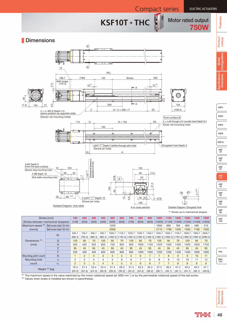
48
ELECTRIC ACTUATORSCompact series
Pro
duc
t Li
neup
Tec
hn
ica
l M
ate
ria
ls
THC
TNU/TJU
KSF8
KSF4
KSF10
KSF 5T
KSF 6T
KSF 8T
KSF 10U
KSF 4U
KSF 5U
KSF 6U
Spec
ifica
tions
/ D
imen
sion
sM
odel
C
onfig
urat
ion
Fea
ture
s
ELECTRIC ACTUATORSCompact series
KSF5
KSF6
ELECTRIC ACTUATORSCompact series
KSF 10T
KSF 8U
ELECTRIC ACTUATORSCompact series
KSF10T + THC Motor rated output750W
Dimensions
Stroke [mm] (Stroke between mechanical stoppers)
100 (120)
200 (220)
300 (320)
400 (420)
500 (520)
600 (620)
700 (720)
800 (820)
900 (920)
1000 (1020)
1100 (1120)
1200 (1220)
1300 (1320)
1400 (1420)
1500 (1520)
Maximum speed 2 [mm/s]
Ball screw lead: 25 mm 1250 1050 890 760 660 580 510Ball screw lead: 50 mm 2500 2110 1790 1530 1330 1160 1030
Dimensions 3 [mm]
AL645.7 (682.3)
745.7 (782.3)
845.7 (882.3)
945.7 (982.3)
1045.7 (1082.3)
1145.7 (1182.3)
1245.7 (1282.3)
1345.7 (1382.3)
1445.7 (1482.3)
1545.7 (1582.3)
1645.7 (1682.3)
1745.7 (1782.3)
1845.7 (1882.3)
1945.7 (1982.3)
2045.7 (2082.3)
G 120 95 70 120 95 70 120 95 70 120 95 70 120 95 70H 320 420 520 620 720 820 920 1020 1120 1220 1320 1420 1520 1620 1720Z 95 45 95 45 95 45 95 45 95 45 95 45 95 45 95F 200 400 400 600 600 800 800 1000 1000 1200 1200 1400 1400 1600 1600
Mounting pitch count N 1 2 3 3 4 5 5 6 7 7 8 9 9 10 11Mounting hole
countn 2 3 4 4 5 6 6 7 8 8 9 10 10 11 12n1 2 3 3 4 4 5 5 6 6 7 7 8 8 9 9
Weight 3 [kg]19.4 (20.3)
21.4 (22.3)
23.4 (24.3)
25.4 (26.3)
27.4 (28.3)
29.3 (30.2)
31.3 (32.2)
33.3 (34.2)
35.3 (36.2)
37.2 (38.1)
39.2 (40.1)
41.2 (42.1)
43.2 (44.1)
45.2 (46.1)
47.1 (48.0)
2 The maximum speed is the value restricted by the motor rotational speed (at 3000 min-1) or by the permissible rotational speed of the ball screw.3 Values when brake is installed are shown in parentheses.
Detailed Diagram: Elongated HoleDetailed Diagram: Sub-table
1 Stroke up to mechanical stopper.
A
A
A-A cross section
B
(2)
H
(G)115
Elongated hole Depth 5
N × 150
(2)
5H7+0.0120 Depth 5 (drilled through pilot hole)
(Dowel pin hole)
1
5+
0.03
00
1
(R)
150
(R)
10 10
27
G
Stroke (95)(190) 140
35
104
12
108.7With brake
(145.3)
(AL)
(n1-1) × 200 = F
200
(Z)Z
60
7
25
20
120
110±
0.02
(Dim
ensio
nal to
leran
ce is
ap
plica
ble to
5 o
nly)
4-M8 Depth 16(Sub-table mounting hole)
10
2- 5H7 +0.0120 Depth 10
(Dowel pin hole)
90 ±0.02
4-M4 Depth 8 (From the back surface)(Sensor dog mounting hole)
49
0.5(1.2) (1) 104
(106.4)
From surface B
2 × n- 9 through 14 counter bore Depth 8.4(Outer rail mounting hole)
2 × n1-M2.6 Depth 3.5 (same position as opposite side)(Sensor rail mounting holes)
41.4
4.6
100
100
20
(0.8
)
50 2513
14.5
63
95
124
2 - (C3)
(11) 1 1
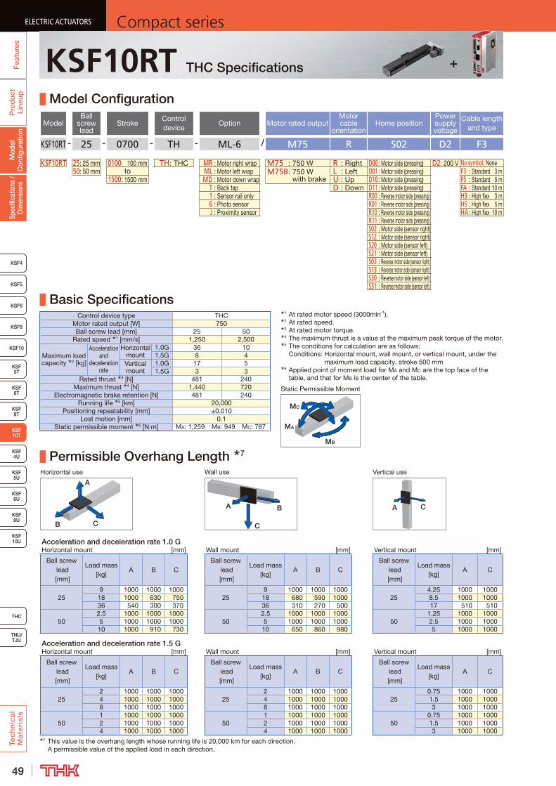
49
ELECTRIC ACTUATORS Compact seriesP
rod
uct
Line
upTe
ch
nic
al
Ma
teri
als
KSF8
KSF4
KSF10
KSF 5T
KSF 6T
KSF 8T
KSF 10U
KSF 4U
KSF 5U
KSF 6U
TNU/TJU
THC
Spec
ifica
tions
/ D
imen
sion
sM
odel
C
onfig
urat
ion
Fea
ture
sELECTRIC ACTUATORS Compact series
KSF5
KSF6
ELECTRIC ACTUATORS Compact series
KSF 10T
KSF 8U
ELECTRIC ACTUATORS Compact series
KSF10RT THC Specifications
Model Configuration
ModelBall
screw lead
StrokeControl device
Option Motor rated outputMotor cable
orientationHome position
Power supply voltage
Cable length and type
KSF10RT - 25 - 0700 - TH - ML-6 / M75 R S02 D2 F3
KSF10RT 25: 25 mm 0100: 100 mm TH: THC MR : Motor right wrap M75 : 750 W R : Right D00 : Motor side (pressing) D2: 200 V No symbol: None50: 50 mm to ML : Motor left wrap M75B: 750 W
with brakeL : Left D01 : Motor side (pressing) F3 : Standard 3 m
1500: 1500 mm MD : Motor down wrap U : Up D10 : Motor side (pressing) F5 : Standard 5 m T : Back tap D : Down D11 : Motor side (pressing) FA : Standard 10 m 1 : Sensor rail only R00 : Reverse motor side (pressing) H3 : High flex 3 m 6 : Photo sensor R01 : Reverse motor side (pressing) H5 : High flex 5 m J : Proximity sensor R10 : Reverse motor side (pressing) HA : High flex 10 m
R11 : Reverse motor side (pressing)S02 : Motor side (sensor right)S12 : Motor side (sensor right)S20 : Motor side (sensor left)S21 : Motor side (sensor left)S03 : Reverse motor side (sensor right)S13 : Reverse motor side (sensor right)S30 : Reverse motor side (sensor left)S31 : Reverse motor side (sensor left)
Basic SpecificationsControl device type THC
Motor rated output [W] 750Ball screw lead [mm] 25 50
Rated speed 1 [mm/s] 1,250 2,500
Maximum load capacity 2 [kg]
Acceleration and
deceleration rate
Horizontal mount
1.0G 36 101.5G 8 4
Vertical mount
1.0G 17 51.5G 3 3
Rated thrust 3 [N] 481 240Maximum thrust 4 [N] 1,440 720
Electromagnetic brake retention [N] 481 240Running life 5 [km] 20,000
Positioning repeatability [mm] ±0.010Lost motion [mm] 0.1
Static permissible moment 6 [N·m] MA: 1,259 MB: 949 MC: 787
Permissible Overhang Length 7
Horizontal use Wall use Vertical use
CB
A
A B
C
A C
Acceleration and deceleration rate 1.0 GHorizontal mount [mm] Wall mount [mm] Vertical mount [mm]
Ball screw lead [mm]
Load mass [kg]
A B CBall screw
lead [mm]
Load mass [kg]
A B CBall screw
lead [mm]
Load mass [kg]
A C
259 1000 1000 1000
259 1000 1000 1000
254.25 1000 1000
18 1000 630 750 18 680 590 1000 8.5 1000 100036 540 300 370 36 310 270 500 17 510 510
502.5 1000 1000 1000
502.5 1000 1000 1000
501.25 1000 1000
5 1000 1000 1000 5 1000 1000 1000 2.5 1000 100010 1000 910 730 10 650 860 980 5 1000 1000
Acceleration and deceleration rate 1.5 GHorizontal mount [mm] Wall mount [mm] Vertical mount [mm]
Ball screw lead [mm]
Load mass [kg]
A B CBall screw
lead [mm]
Load mass [kg]
A B CBall screw
lead [mm]
Load mass [kg]
A C
252 1000 1000 1000
252 1000 1000 1000
250.75 1000 1000
4 1000 1000 1000 4 1000 1000 1000 1.5 1000 10008 1000 1000 1000 8 1000 1000 1000 3 1000 1000
501 1000 1000 1000
501 1000 1000 1000
500.75 1000 1000
2 1000 1000 1000 2 1000 1000 1000 1.5 1000 10004 1000 1000 1000 4 1000 1000 1000 3 1000 1000
7 This value is the overhang length whose running life is 20,000 km for each direction. A permissible value of the applied load in each direction.
MB
MA
MC
Static Permissible Moment
1 At rated motor speed (3000min-1).2 At rated speed.3 At rated motor torque.4 The maximum thrust is a value at the maximum peak torque of the motor.5 The conditions for calculation are as follows:
Conditions: Horizontal mount, wall mount, or vertical mount, under the maximum load capacity, stroke 500 mm
6 Applied point of moment load for MA and MC are the top face of the table, and that for MB is the center of the table.
+
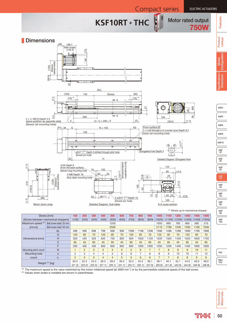
50
ELECTRIC ACTUATORSCompact series
Pro
duc
t Li
neup
Tec
hn
ica
l M
ate
ria
ls
THC
TNU/TJU
KSF8
KSF4
KSF10
KSF 5T
KSF 6T
KSF 8T
KSF 10U
KSF 4U
KSF 5U
KSF 6U
Spec
ifica
tions
/ D
imen
sion
sM
odel
C
onfig
urat
ion
Fea
ture
s
ELECTRIC ACTUATORSCompact series
KSF5
KSF6
ELECTRIC ACTUATORSCompact series
KSF 10T
KSF 8U
ELECTRIC ACTUATORSCompact series
KSF10RT + THC Motor rated output750W
Dimensions
Stroke [mm] (Stroke between mechanical stoppers)
100 (120)
200 (220)
300 (320)
400 (420)
500 (520)
600 (620)
700 (720)
800 (820)
900 (920)
1000 (1020)
1100 (1120)
1200 (1220)
1300 (1320)
1400 (1420)
1500 (1520)
Maximum speed 2 [mm/s]
Ball screw lead: 25 mm 1250 1050 890 760 660 580 510Ball screw lead: 50 mm 2500 2110 1790 1530 1330 1160 1030
Dimensions [mm]
AL 498 598 698 798 898 998 1098 1198 1298 1398 1498 1598 1698 1798 1898G 120 95 70 120 95 70 120 95 70 120 95 70 120 95 70H 320 420 520 620 720 820 920 1020 1120 1220 1320 1420 1520 1620 1720Z 95 45 95 45 95 45 95 45 95 45 95 45 95 45 95F 200 400 400 600 600 800 800 1000 1000 1200 1200 1400 1400 1600 1600
Mounting pitch count N 1 2 3 3 4 5 5 6 7 7 8 9 9 10 11Mounting hole
countn 2 3 4 4 5 6 6 7 8 8 9 10 10 11 12n1 2 3 3 4 4 5 5 6 6 7 7 8 8 9 9
Weight 3 [kg]20.3 (21.2)
22.3 (23.2)
24.3 (25.2)
26.2 (27.1)
28.2 (29.1)
30.2 (31.1)
32.2 (33.1)
34.2 (35.1)
36.1 (37.0)
38.1 (39.0)
40.1 (41.0)
42.1 (43.0)
44.0 (44.9)
46.0 (46.9)
48.0 (48.9)
2 The maximum speed is the value restricted by the motor rotational speed (at 3000 min-1) or by the permissible rotational speed of the ball screw.3 Values when brake is installed are shown in parentheses.
A
A
Motor down wrap Detailed Diagram: Sub-table
Detailed Diagram: Elongated Hole
1 Stroke up to mechanical stopper.
A-A cross section
B
2 × n1-M2.6 Depth 3.5 (same position as opposite side) (Z)Z (n1-1) × 200 = F
(AL)
200
27
(10) 1 (10) 1
Stroke
60
7
25
20
120
110±
0.02
4-M8 Depth 16(Sub-table mounting hole)
10
2- 5H7 +0.012 0 Depth 10
(Dowel pin hole)
90±0.02
4-M4 Depth 8 (From the back surface)(Sensor dog mounting hole)
1
140 (95)(163)
1
5+
0.03
0 0
(R)(R)
(120
)(D
ista
nce
betw
een
shaf
ts)
(128
.5)21
6(1
.7)
(1.7
)
(80)
From surface B2 × n- 9 through 14 counter bore Depth 8.4(Outer rail mounting hole)
46
150
5H7 + 0.012 Depth 5 (drilled through pilot hole)(Dowel pin hole)
0Elongated hole Depth 5
H
G (G)N × 150
35
(41)
104
229.5 (1.7)
40
(9)
(80)
108.7With brake
(145.3)
(2)
□80
(13)
(49)
(38.
5)(1
20)
(Dist
ance
be
twee
n sh
afts
)0.
5(1
1)
41.4
4.6
100
100
20
(0.8
)
50 2513
14.5
63
95
124
2 - (C3)
(Sensor rail mounting holes)(D
imen
siona
l toler
ance
is
appli
cable
to 5
only)

51
ELECTRIC ACTUATORS Compact seriesP
rod
uct
Line
upTe
ch
nic
al
Ma
teri
als
KSF8
KSF4
KSF 10T
KSF10
KSF 5T
KSF 6T
KSF 8T
KSF 10U
KSF 5U
KSF 6U
KSF 8U
TNU/TJU
THC
Spec
ifica
tions
/ D
imen
sion
sM
odel
C
onfig
urat
ion
Fea
ture
sELECTRIC ACTUATORS Compact series
KSF5
KSF6
ELECTRIC ACTUATORS Compact series
KSF 4U
KSF5
ELECTRIC ACTUATORS Compact series
KSF4U THC Specifications
Model Configuration
ModelBall
screw lead
StrokeControl device
Option Motor rated outputMotor cable
orientationHome position
Power supply voltage
Cable length and type
KSF4U - 10 - 0050 - TH - T-6 / M10 L S02 D1 F3
KSF4U 10: 10 mm 0050: 50 mm TH: THC No symbol: None M10 : 100 W R : Right D00 : Motor side (pressing) D1: 100 V No symbol: None16: 16 mm to T : Back tap M10B: 100 W
with brakeL : Left D01 : Motor side (pressing) D2: 200 V F3 : Standard 3 m
0900: 900 mm 1 : Sensor rail only U : Up D10 : Motor side (pressing) F5 : Standard 5 m 6 : Photo sensor D : Down D11 : Motor side (pressing) FA : Standard 10 m J : Proximity sensor R00 : Reverse motor side (pressing) H3 : High flex 3 m
R01 : Reverse motor side (pressing) H5 : High flex 5 mR10 : Reverse motor side (pressing) HA : High flex 10 mR11 : Reverse motor side (pressing)S02 : Motor side (sensor right)S12 : Motor side (sensor right)S20 : Motor side (sensor left)S21 : Motor side (sensor left)S03 : Reverse motor side (sensor right)S13 : Reverse motor side (sensor right)S30 : Reverse motor side (sensor left)S31 : Reverse motor side (sensor left)
Basic SpecificationsControl device type THC
Motor rated output [W] 100Ball screw lead [mm] 10 16
Rated speed 1 [mm/s] 500 800
Maximum load capacity 2 [kg]
Acceleration and
deceleration rate
Horizontal mount
0.5G 12 −1.0G 8 82.0G − 6
Vertical mount
0.5G 8 −1.0G 6 62.0G − 4
Rated thrust 3 [N] 180 112Maximum thrust 4 [N] 537 336
Electromagnetic brake retention [N] 180 112Running life 5 [km] 10,000 20,000
Positioning repeatability [mm] ±0.010Lost motion [mm] 0.1
Static permissible moment 6 [N·m] MA: 103 MB: 95 MC: 58
Permissible Overhang Length 7
Horizontal use Wall use Vertical use
CB
A
A B
C
A C
Acceleration and deceleration rate: lead 10 mm: 0.5 G, lead 16 mm: 1.0 GHorizontal mount [mm] Wall mount [mm] Vertical mount [mm]
Ball screw lead [mm]
Load mass [kg]
A B CBall screw
lead [mm]
Load mass [kg]
A B CBall screw
lead [mm]
Load mass [kg]
A C
103 400 210 350
103 320 200 400
102 310 310
6 400 100 170 6 140 90 400 4 150 15012 270 40 80 12 50 30 240 8 60 60
162 400 260 350
162 320 240 400
161.5 300 300
4 310 120 170 4 140 110 290 3 140 1408 140 50 80 8 50 40 120 6 60 60
Acceleration and deceleration rate - lead 10 mm: 1.0 G, lead 16 mm: 2.0 GHorizontal mount [mm] Wall mount [mm] Vertical mount [mm]
Ball screw lead [mm]
Load mass [kg]
A B CBall screw
lead [mm]
Load mass [kg]
A B CBall screw
lead [mm]
Load mass [kg]
A C
102 400 330 400
102 400 310 400
101.5 400 400
4 400 160 240 4 220 140 400 3 200 2008 260 70 120 8 90 60 250 6 90 90
161.5 400 400 400
161.5 370 330 400
161 400 400
3 330 210 250 3 170 150 250 2 200 2006 120 80 100 6 70 60 110 4 90 90
7 This value is the overhang length whose running life is 10,000 km (20,000 km for lead 16 mm) for each direction. A permissible value of the applied load in each direction.
MB
MA
MC
Static Permissible Moment
1 At rated motor speed (3000min-1).2 At rated speed.3 At rated motor torque.4 The maximum thrust is a value at the maximum peak torque of the motor.5 The conditions for calculation are as follows:
Conditions: Horizontal mount, wall mount, or vertical mount, under the maximum load capacity, stroke 500 mm
6 Applied point of moment load for MA and MC are the top face of the table, and that for MB is the center of the table.
+
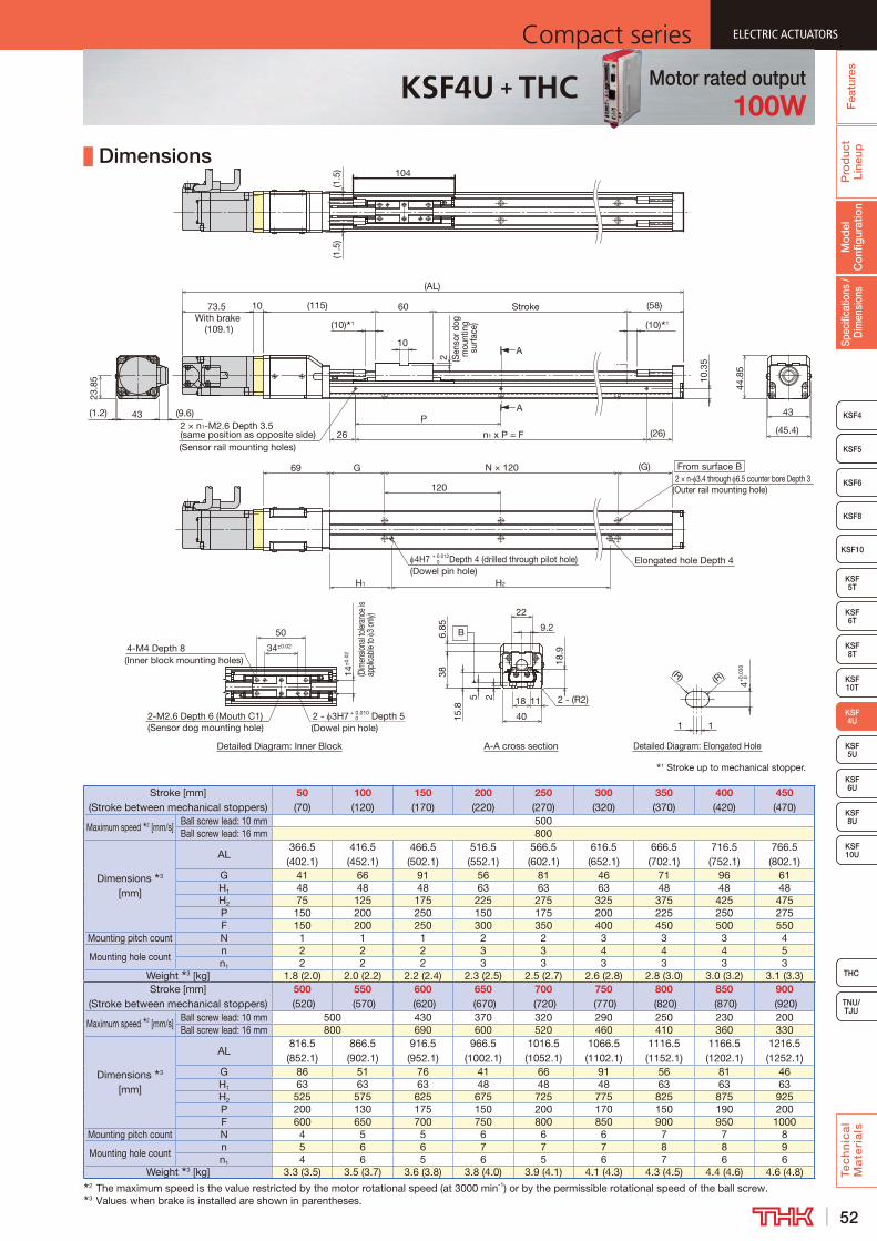
52
ELECTRIC ACTUATORSCompact series
Pro
duc
t Li
neup
Tec
hn
ica
l M
ate
ria
ls
THC
TNU/TJU
KSF8
KSF4
KSF 10T
KSF10
KSF 5T
KSF 6T
KSF 8T
KSF 10U
KSF 5U
KSF 6U
KSF 8U
Spec
ifica
tions
/ D
imen
sion
sM
odel
C
onfig
urat
ion
Fea
ture
s
ELECTRIC ACTUATORSCompact series
KSF5
KSF6
ELECTRIC ACTUATORSCompact series
KSF 4U
KSF5
ELECTRIC ACTUATORSCompact series
KSF4U + THC Motor rated output100W
Dimensions
Stroke [mm] (Stroke between mechanical stoppers)
50 (70)
100 (120)
150 (170)
200 (220)
250 (270)
300 (320)
350 (370)
400 (420)
450 (470)
Maximum speed 2 [mm/s]Ball screw lead: 10 mm 500Ball screw lead: 16 mm 800
Dimensions 3 [mm]
AL366.5 (402.1)
416.5 (452.1)
466.5 (502.1)
516.5 (552.1)
566.5 (602.1)
616.5 (652.1)
666.5 (702.1)
716.5 (752.1)
766.5 (802.1)
G 41 66 91 56 81 46 71 96 61H1 48 48 48 63 63 63 48 48 48H2 75 125 175 225 275 325 375 425 475P 150 200 250 150 175 200 225 250 275F 150 200 250 300 350 400 450 500 550
Mounting pitch count N 1 1 1 2 2 3 3 3 4
Mounting hole countn 2 2 2 3 3 4 4 4 5n1 2 2 2 3 3 3 3 3 3
Weight 3 [kg] 1.8 (2.0) 2.0 (2.2) 2.2 (2.4) 2.3 (2.5) 2.5 (2.7) 2.6 (2.8) 2.8 (3.0) 3.0 (3.2) 3.1 (3.3)Stroke [mm]
(Stroke between mechanical stoppers)500
(520)550
(570)600
(620)650
(670)700
(720)750
(770)800
(820)850
(870)900
(920)
Maximum speed 2 [mm/s]Ball screw lead: 10 mm 500 430 370 320 290 250 230 200Ball screw lead: 16 mm 800 690 600 520 460 410 360 330
Dimensions 3 [mm]
AL816.5 (852.1)
866.5 (902.1)
916.5 (952.1)
966.5 (1002.1)
1016.5 (1052.1)
1066.5 (1102.1)
1116.5 (1152.1)
1166.5 (1202.1)
1216.5 (1252.1)
G 86 51 76 41 66 91 56 81 46H1 63 63 63 48 48 48 63 63 63H2 525 575 625 675 725 775 825 875 925P 200 130 175 150 200 170 150 190 200F 600 650 700 750 800 850 900 950 1000
Mounting pitch count N 4 5 5 6 6 6 7 7 8
Mounting hole countn 5 6 6 7 7 7 8 8 9n1 4 6 5 6 5 6 7 6 6
Weight 3 [kg] 3.3 (3.5) 3.5 (3.7) 3.6 (3.8) 3.8 (4.0) 3.9 (4.1) 4.1 (4.3) 4.3 (4.5) 4.4 (4.6) 4.6 (4.8)2 The maximum speed is the value restricted by the motor rotational speed (at 3000 min-1) or by the permissible rotational speed of the ball screw.3 Values when brake is installed are shown in parentheses.
1 Stroke up to mechanical stopper.
Detailed Diagram: Elongated Hole
A
A
Detailed Diagram: Inner Block A-A cross section
B
From surface B2 × n- 3.4 through 6.5 counter bore Depth 3
(Outer rail mounting hole)
H1
4H7 + 0.012 0 Depth 4 (drilled through pilot hole)
(Dowel pin hole)Elongated hole Depth 4
4+0.
030
0
11
(R) (R)
69
H2
120
43
G N × 120
44.8
5
(10) 1
4-M4 Depth 8(Inner block mounting holes)
2-M2.6 Depth 6 (Mouth C1)(Sensor dog mounting hole)
2 - 3H7 + 0.010 0 Depth 5
(Dowel pin hole)
50
34±0.02
(1.5
)(1
.5)
14±
0.02
(D
imen
siona
l toler
ance
is
appli
cable
to 3
only
)
(58)Stroke
(10) 1
(115)
2
10
60
(G)
26
P
n1 x P = F (26)
10.3
5
2 × n1-M2.6 Depth 3.5 (same position as opposite side)(Sensor rail mounting holes)
(AL)
1073.5With brake
(109.1)
23.8
5
43 (9.6)
(45.4)
185 2 11
15.8
2 - (R2)
9.2
18.9
386.
85
40
22
(1.2)
104
(Sen
sor d
og
mou
ntin
g su
rface
)

53
ELECTRIC ACTUATORS Compact seriesP
rod
uct
Line
upTe
ch
nic
al
Ma
teri
als
KSF8
KSF4
KSF 10T
KSF10
KSF 5T
KSF 6T
KSF 8T
KSF 10U
KSF 5U
KSF 6U
KSF 8U
TNU/TJU
THC
Spec
ifica
tions
/ D
imen
sion
sM
odel
C
onfig
urat
ion
Fea
ture
sELECTRIC ACTUATORS Compact series
KSF5
KSF6
ELECTRIC ACTUATORS Compact series
KSF 4U
KSF5
ELECTRIC ACTUATORS Compact series
KSF4RU THC Specifications
Model Configuration
ModelBall
screw lead
StrokeControl device
Option Motor rated outputMotor cable
orientationHome position
Power supply voltage
Cable length and type
KSF4RU - 10 - 0050 - TH - ML-6 / M10 R S02 D1 F3
KSF4RU 10: 10 mm 0050: 50 mm TH: THC MR : Motor right wrap M10 : 100 W R : Right D00 : Motor side (pressing) D1: 100 V No symbol: None16: 16 mm to ML : Motor left wrap M10B: 100 W
with brakeL : Left D01 : Motor side (pressing) D2: 200 V F3 : Standard 3 m
0900: 900 mm MD : Motor down wrap U : Up D10 : Motor side (pressing) F5 : Standard 5 m T : Back tap D : Down D11 : Motor side (pressing) FA : Standard 10 m 1 : Sensor rail only R00 : Reverse motor side (pressing) H3 : High flex 3 m 6 : Photo sensor R01 : Reverse motor side (pressing) H5 : High flex 5 m J : Proximity sensor R10 : Reverse motor side (pressing) HA : High flex 10 m
R11 : Reverse motor side (pressing)S02 : Motor side (sensor right)S12 : Motor side (sensor right)S20 : Motor side (sensor left)S21 : Motor side (sensor left)S03 : Reverse motor side (sensor right)S13 : Reverse motor side (sensor right)S30 : Reverse motor side (sensor left)S31 : Reverse motor side (sensor left)
Basic SpecificationsControl device type THC
Motor rated output [W] 100Ball screw lead [mm] 10 16
Rated speed 1 [mm/s] 500 800
Maximum load capacity 2 [kg]
Acceleration and
deceleration rate
Horizontal mount
0.5G 12 −1.0G 8 82.0G − 6
Vertical mount
0.5G 8 −1.0G 6 62.0G − 4
Rated thrust 3 [N] 160 100Maximum thrust 4 [N] 478 298
Electromagnetic brake retention [N] 160 100Running life 5 [km] 10,000 20,000
Positioning repeatability [mm] ±0.010Lost motion [mm] 0.1
Static permissible moment 6 [N·m] MA: 103 MB: 95 MC: 58
Permissible Overhang Length 7
Horizontal use Wall use Vertical use
CB
A
A B
C
A C
Acceleration and deceleration rate: lead 10 mm: 0.5 G, lead 16 mm: 1.0 GHorizontal mount [mm] Wall mount [mm] Vertical mount [mm]
Ball screw lead [mm]
Load mass [kg]
A B CBall screw
lead [mm]
Load mass [kg]
A B CBall screw
lead [mm]
Load mass [kg]
A C
103 400 210 350
103 320 200 400
102 310 310
6 400 100 170 6 140 90 400 4 150 15012 270 40 80 12 50 30 240 8 60 60
162 400 260 350
162 320 240 400
161.5 300 300
4 310 120 170 4 140 110 290 3 140 1408 140 50 80 8 50 40 120 6 60 60
Acceleration and deceleration rate: lead 10 mm: 1.0 G, lead 16 mm: 2.0 GHorizontal mount [mm] Wall mount [mm] Vertical mount [mm]
Ball screw lead [mm]
Load mass [kg]
A B CBall screw
lead [mm]
Load mass [kg]
A B CBall screw
lead [mm]
Load mass [kg]
A C
102 400 330 400
102 400 310 400
101.5 400 400
4 400 160 240 4 220 140 400 3 200 2008 260 70 120 8 90 60 250 6 90 90
161.5 400 400 400
161.5 370 330 400
161 400 400
3 330 210 250 3 170 150 250 2 200 2006 120 80 100 6 70 60 110 4 90 90
7 This value is the overhang length whose running life is 10,000 km (20,000 km for lead 16 mm) for each direction. A permissible value of the applied load in each direction.
MB
MA
MC
Static Permissible Moment
1 At rated motor speed (3000min-1).2 At rated speed.3 At rated motor torque.4 The maximum thrust is a value at the maximum peak torque of the motor.5 The conditions for calculation are as follows:
Conditions: Horizontal mount, wall mount, or vertical mount, under the maximum load capacity, stroke 500 mm
6 Applied point of moment load for MA and MC are the top face of the table, and that for MB is the center of the table.
+

54
ELECTRIC ACTUATORSCompact series
Pro
duc
t Li
neup
Tec
hn
ica
l M
ate
ria
ls
THC
TNU/TJU
KSF8
KSF4
KSF 10T
KSF10
KSF 5T
KSF 6T
KSF 8T
KSF 10U
KSF 5U
KSF 6U
KSF 8U
Spec
ifica
tions
/ D
imen
sion
sM
odel
C
onfig
urat
ion
Fea
ture
s
ELECTRIC ACTUATORSCompact series
KSF5
KSF6
ELECTRIC ACTUATORSCompact series
KSF 4U
KSF5
ELECTRIC ACTUATORSCompact series
KSF4RU + THC Motor rated output100W
Dimensions
Stroke [mm] (Stroke between mechanical stoppers)
50 (70)
100 (120)
150 (170)
200 (220)
250 (270)
300 (320)
350 (370)
400 (420)
450 (470)
Maximum speed 2 [mm/s] Ball screw lead: 10 mm 500Ball screw lead: 16 mm 800
Dimensions [mm]
AL 264 314 364 414 464 514 564 614 664G 41 66 91 56 81 46 71 96 61H1 48 48 48 63 63 63 48 48 48H2 75 125 175 225 275 325 375 425 475P 150 200 250 150 175 200 225 250 275F 150 200 250 300 350 400 450 500 550
Mounting pitch count N 1 1 1 2 2 3 3 3 4
Mounting hole count n 2 2 2 3 3 4 4 4 5n1 2 2 2 3 3 3 3 3 3
Weight 3 [kg] 2.0 (2.2) 2.2 (2.4) 2.3 (2.5) 2.5 (2.7) 2.7 (2.9) 2.8 (3.0) 3.0 (3.2) 3.1 (3.3) 3.3 (3.5)Stroke [mm]
(Stroke between mechanical stoppers)500 (520)
550 (570)
600 (620)
650 (670)
700 (720)
750 (770)
800 (820)
850 (870)
900 (920)
Maximum speed 2 [mm/s] Ball screw lead: 10 mm 500 430 370 320 290 250 230 200Ball screw lead: 16 mm 800 690 600 520 460 410 360 330
Dimensions [mm]
AL 714 764 814 864 914 964 1014 1064 1114G 86 51 76 41 66 91 56 81 46H1 63 63 63 48 48 48 63 63 63H2 525 575 625 675 725 775 825 875 925P 200 130 175 150 200 170 150 190 200F 600 650 700 750 800 850 900 950 1000
Mounting pitch count N 4 5 5 6 6 6 7 7 8
Mounting hole count n 5 6 6 7 7 7 8 8 9n1 4 6 5 6 5 6 7 6 6
Weight 3 [kg] 3.5 (3.7) 3.6 (3.8) 3.8 (4.0) 3.9 (4.1) 4.1 (4.3) 4.3 (4.5) 4.4 (4.6) 4.6 (4.8) 4.7 (4.9)2 The maximum speed is the value restricted by the motor rotational speed (at 3000 min-1) or by the permissible rotational speed of the ball screw.3 Values when brake is installed are shown in parentheses.
A
A
Detailed Diagram: Elongated Hole
4+
0.03
00
4H7 +0.0120 Depth 4 (drilled through pilot hole)
(Dowel pin hole)
G N × 120
120
(26)
10.3
5
(n1 - 1) × P = F
(58)
2 × n1-M2.6 Depth 3.5 (same position as opposite side)(Sensor rail mounting holes)
10
60
26
P
2 (Sen
sor d
og
moun
ting s
urfac
e)
(AL)
1
Stroke
(10) 1
From surface B
2 × n- 3.4 through 6.5 counter bore Depth 3(Outer rail mounting hole)
(96)
Elongated hole Depth 4
73.5With brake
(109.1)
104
(1.5
)
(10) 1
H2
1
(R) (R)
H1
(G)
(31)
□40
(11.
1)
0.35
(0.1) (1.7)
43
(42)
(2.8
5)
113.5
21
(20)
(60)
(Dist
ance
be
twee
n sh
afts
)
1 Stroke up to mechanical stopper.
Detailed Diagram: Inner BlockMotor down wrap A-A cross section
B4-M4 Depth 8(Inner block mounting holes)
50
2- 3H7+0.0100 Depth 5
(Dowel pin hole)2-M2.6 Depth 4.5 (Mouth C1)(Sensor dog mounting hole)
34 ±0.02
14±
0.02
(Dim
ensio
nal to
leran
ce
is ap
plica
ble to
3 on
ly)
112
(68.
2)
(60)
(Dis
tanc
e be
twee
n sh
afts
)
(1.7
)(1
.7)
185 2 11
15.8 2 - (R2)
9.2
18.9
386.
85
40
22
(42)
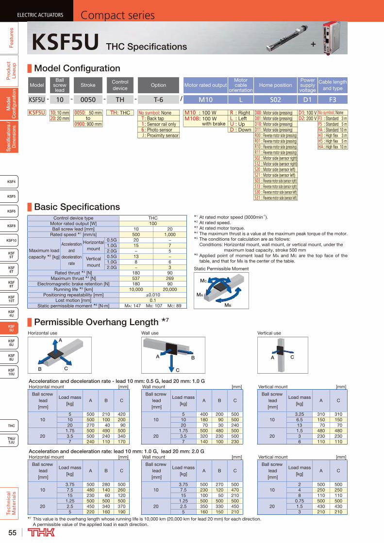
55
ELECTRIC ACTUATORS Compact seriesP
rod
uct
Line
upTe
ch
nic
al
Ma
teri
als
KSF8
KSF4
KSF 10T
KSF 5T
KSF 6T
KSF 8T
KSF 10U
KSF 4U
KSF 6U
KSF 8U
TNU/TJU
THC
Spec
ifica
tions
/ D
imen
sion
sM
odel
C
onfig
urat
ion
Fea
ture
sELECTRIC ACTUATORS Compact series
KSF5
KSF6
ELECTRIC ACTUATORS Compact series
KSF 5U
KSF10
ELECTRIC ACTUATORS Compact series
KSF5U THC Specifications
Model Configuration
ModelBall
screw lead
StrokeControl device
Option Motor rated outputMotor cable
orientationHome position
Power supply voltage
Cable length and type
KSF5U - 10 - 0050 - TH - T-6 / M10 L S02 D1 F3
KSF5U 10: 10 mm 0050: 50 mm TH: THC No symbol: None M10 : 100 W R : Right D00 : Motor side (pressing) D1: 100 V No symbol: None20: 20 mm to T : Back tap M10B: 100 W
with brakeL : Left D01 : Motor side (pressing) D2: 200 V F3 : Standard 3 m
0900: 900 mm 1 : Sensor rail only U : Up D10 : Motor side (pressing) F5 : Standard 5 m 6 : Photo sensor D : Down D11 : Motor side (pressing) FA : Standard 10 m J : Proximity sensor R00 : Reverse motor side (pressing) H3 : High flex 3 m
R01 : Reverse motor side (pressing) H5 : High flex 5 mR10 : Reverse motor side (pressing) HA : High flex 10 mR11 : Reverse motor side (pressing)S02 : Motor side (sensor right)S12 : Motor side (sensor right)S20 : Motor side (sensor left)S21 : Motor side (sensor left)S03 : Reverse motor side (sensor right)S13 : Reverse motor side (sensor right)S30 : Reverse motor side (sensor left)S31 : Reverse motor side (sensor left)
Basic SpecificationsControl device type THC
Motor rated output [W] 100Ball screw lead [mm] 10 20
Rated speed 1 [mm/s] 500 1,000
Maximum load capacity 2 [kg]
Acceleration and
deceleration rate
Horizontal mount
0.5G 20 −1.0G 15 72.0G − 5
Vertical mount
0.5G 13 −1.0G 8 62.0G − 3
Rated thrust 3 [N] 180 90Maximum thrust 4 [N] 537 269
Electromagnetic brake retention [N] 180 90Running life 5 [km] 10,000 20,000
Positioning repeatability [mm] ±0.010Lost motion [mm] 0.1
Static permissible moment 6 [N·m] MA: 147 MB: 107 MC: 89
Permissible Overhang Length 7
Horizontal use Wall use Vertical use
CB
A
A B
C
A C
Acceleration and deceleration rate - lead 10 mm: 0.5 G, lead 20 mm: 1.0 GHorizontal mount [mm] Wall mount [mm] Vertical mount [mm]
Ball screw lead [mm]
Load mass [kg]
A B CBall screw
lead [mm]
Load mass [kg]
A B CBall screw
lead [mm]
Load mass [kg]
A C
105 500 210 420
105 400 200 500
103.25 310 310
10 500 100 200 10 180 90 500 6.5 150 15020 270 40 90 20 70 30 240 13 70 70
201.75 500 490 500
201.75 500 480 500
201.5 480 480
3.5 500 240 340 3.5 320 230 500 3 230 2307 240 110 170 7 140 100 230 6 110 110
Acceleration and deceleration rate: lead 10 mm: 1.0 G, lead 20 mm: 2.0 GHorizontal mount [mm] Wall mount [mm] Vertical mount [mm]
Ball screw lead [mm]
Load mass [kg]
A B CBall screw
lead [mm]
Load mass [kg]
A B CBall screw
lead [mm]
Load mass [kg]
A C
103.75 500 280 500
103.75 500 270 500
102 500 500
7.5 480 140 260 7.5 230 120 470 4 250 25015 230 60 120 15 100 50 210 8 110 110
201.25 500 500 500
201.25 500 500 500
200.75 500 500
2.5 450 340 370 2.5 350 330 450 1.5 430 4305 220 160 190 5 160 150 210 3 210 210
7 This value is the overhang length whose running life is 10,000 km (20,000 km for lead 20 mm) for each direction. A permissible value of the applied load in each direction.
MB
MA
MC
Static Permissible Moment
1 At rated motor speed (3000min-1).2 At rated speed.3 At rated motor torque.4 The maximum thrust is a value at the maximum peak torque of the motor.5 The conditions for calculation are as follows:
Conditions: Horizontal mount, wall mount, or vertical mount, under the maximum load capacity, stroke 500 mm
6 Applied point of moment load for MA and MC are the top face of the table, and that for MB is the center of the table.
+

56
ELECTRIC ACTUATORSCompact series
Pro
duc
t Li
neup
Tec
hn
ica
l M
ate
ria
ls
THC
TNU/TJU
KSF8
KSF4
KSF 10T
KSF 5T
KSF 6T
KSF 8T
KSF 10U
KSF 4U
KSF 6U
KSF 8U
Spec
ifica
tions
/ D
imen
sion
sM
odel
C
onfig
urat
ion
Fea
ture
s
ELECTRIC ACTUATORSCompact series
KSF5
KSF6
ELECTRIC ACTUATORSCompact series
KSF 5U
KSF10
ELECTRIC ACTUATORSCompact series
KSF5U + THC Motor rated output100W
Dimensions
Stroke [mm] (Stroke between mechanical stoppers)
50 (70)
100 (120)
150 (170)
200 (220)
250 (270)
300 (320)
350 (370)
400 (420)
450 (470)
Maximum speed 2 [mm/s]Ball screw lead: 10 mm 500Ball screw lead: 20 mm 1000
Dimensions 3 [mm]
AL383.5 (419.1)
433.5 (469.1)
483.5 (519.1)
533.5 (569.1)
583.5 (619.1)
633.5 (669.1)
683.5 (719.1)
733.5 (769.1)
783.5 (819.1)
G 47 72 97 62 87 52 77 102 67H 140 190 240 290 340 390 440 490 540P 150 200 250 150 175 200 225 250 275F 150 200 250 300 350 400 450 500 550
Mounting pitch count N 1 1 1 2 2 3 3 3 4
Mounting hole countn 2 2 2 3 3 4 4 4 5n1 2 2 2 3 3 3 3 3 3
Weight 3 [kg] 2.5 (2.7) 2.7 (2.9) 2.9 (3.1) 3.2 (3.4) 3.4 (3.6) 3.7 (3.9) 3.9 (4.1) 4.2 (4.4) 4.4 (4.6)Stroke [mm]
(Stroke between mechanical stoppers)500 (520)
550 (570)
600 (620)
650 (670)
700 (720)
750 (770)
800 (820)
850 (870)
900 (920)
Maximum speed 2 [mm/s]Ball screw lead: 10 mm 500 440 390 340 310 270 250Ball screw lead: 20 mm 1000 890 780 690 620 550 500
Dimensions 3 [mm]
AL833.5 (869.1)
883.5 (919.1)
933.5 (969.1)
983.5 (1019.1)
1033.5 (1069.1)
1083.5 (1119.1)
1133.5 (1169.1)
1183.5 (1219.1)
1233.5 (1269.1)
G 92 57 82 47 72 97 62 87 52H 590 640 690 740 790 840 890 940 990P 200 130 175 150 200 170 150 190 200F 600 650 700 750 800 850 900 950 1000
Mounting pitch count N 4 5 5 6 6 6 7 7 8
Mounting hole countn 5 6 6 7 7 7 8 8 9n1 4 6 5 6 5 6 7 6 6
Weight 3 [kg] 4.7 (4.9) 4.9 (5.1) 5.1 (5.3) 5.4 (5.6) 5.6 (5.8) 5.9 (6.1) 6.1 (6.3) 6.4 (6.6) 6.6 (6.8)2 The maximum speed is the value restricted by the motor rotational speed (at 3000 min-1) or by the permissible rotational speed of the ball screw.3 Values when brake is installed are shown in parentheses.
1 Stroke up to mechanical stopper.
Detailed Diagram: Elongated Hole
A
A
Detailed Diagram: Inner Block A-A cross section
B
1
4+0.
030
0
1
(R)(R)
(127)
2 (Sen
sor d
og
mou
nting
surfa
ce)
(63)Stroke
(10) 1
14
(10) 1
60
10
37
(1.3
)(1
.3)
N × 120
120
G
H
(G)
104
Elongated hole Depth 4
From surface B2 × n- 4.5 through 8 counter bore Depth 4
(Outer rail mounting hole)
4H7 + 0.012 Depth 4 (drilled through pilot hole) 0
(Dowel pin hole)
32
P
(32)(n1 - 1) × P = F2 × n1-M2.6 Depth 4 (same position as opposite side)(Sensor rail mounting holes)
75
50
34±0.02
21±
0.02
(Dim
ensio
nal t
olera
nce
is ap
plica
ble
to 3
only
)
2- 3H7 + 0.010 Depth 5 0
(Dowel pin hole)
4-M4 Depth 8(Inner block mounting holes)
2-M2.6 Depth 5 (Mouth C1)(Sensor dog mounting hole)
(AL)
1073.5With brake
(109.1)
45
52.6
(55)
(4.8)52.6(1.2)
24
252-(R3)12.5
30
2
21
378
24
11.05
6
50

57
ELECTRIC ACTUATORS Compact seriesP
rod
uct
Line
upTe
ch
nic
al
Ma
teri
als
KSF8
KSF4
KSF 10T
KSF 5T
KSF 6T
KSF 8T
KSF 10U
KSF 4U
KSF 6U
KSF 8U
TNU/TJU
THC
Spec
ifica
tions
/ D
imen
sion
sM
odel
C
onfig
urat
ion
Fea
ture
sELECTRIC ACTUATORS Compact series
KSF5
KSF6
ELECTRIC ACTUATORS Compact series
KSF 5U
KSF10
ELECTRIC ACTUATORS Compact series
KSF5RU THC Specifications
Model Configuration
ModelBall
screw lead
StrokeControl device
Option Motor rated outputMotor cable
orientationHome position
Power supply voltage
Cable length and type
KSF5RU - 10 - 0050 - TH - ML-6 / M10 R S02 D1 F3
KSF5RU 10: 10 mm 0050: 50 mm TH: THC MR : Motor right wrap M10 : 100 W R : Right D00 : Motor side (pressing) D1: 100 V No symbol: None20: 20 mm to ML : Motor left wrap M10B: 100 W
with brakeL : Left D01 : Motor side (pressing) D2: 200 V F3 : Standard 3 m
0900: 900 mm MD : Motor down wrap U : Up D10 : Motor side (pressing) F5 : Standard 5 m T : Back tap D : Down D11 : Motor side (pressing) FA : Standard 10 m 1 : Sensor rail only R00 : Reverse motor side (pressing) H3 : High flex 3 m 6 : Photo sensor R01 : Reverse motor side (pressing) H5 : High flex 5 m J : Proximity sensor R10 : Reverse motor side (pressing) HA : High flex 10 m
R11 : Reverse motor side (pressing)S02 : Motor side (sensor right)S12 : Motor side (sensor right)S20 : Motor side (sensor left)S21 : Motor side (sensor left)S03 : Reverse motor side (sensor right)S13 : Reverse motor side (sensor right)S30 : Reverse motor side (sensor left)S31 : Reverse motor side (sensor left)
Basic SpecificationsControl device type THC
Motor rated output [W] 100Ball screw lead [mm] 10 20
Rated speed 1 [mm/s] 500 1,000
Maximum load capacity 2 [kg]
Acceleration and
deceleration rate
Horizontal mount
0.5G 20 −1.0G 15 72.0G − 4
Vertical mount
0.5G 11 −1.0G 8 52.0G − 2.5
Rated thrust 3 [N] 160 80Maximum thrust 4 [N] 478 239
Electromagnetic brake retention [N] 160 80Running life 5 [km] 10,000 20,000
Positioning repeatability [mm] ±0.010Lost motion [mm] 0.1
Static permissible moment 6 [N·m] MA: 147 MB: 107 MC: 89
Permissible Overhang Length 7
Horizontal use Wall use Vertical use
CB
A
A B
C
A C
Acceleration and deceleration rate - lead 10 mm: 0.5 G, lead 20 mm: 1.0 GHorizontal mount [mm] Wall mount [mm] Vertical mount [mm]
Ball screw lead [mm]
Load mass [kg]
A B CBall screw
lead [mm]
Load mass [kg]
A B CBall screw
lead [mm]
Load mass [kg]
A C
105 500 210 420
105 400 200 500
102.75 380 380
10 500 100 200 10 180 90 500 5.5 180 18020 270 40 90 20 70 30 240 11 80 80
201.75 500 490 500
201.75 500 480 500
201.25 500 500
3.5 500 240 340 3.5 320 230 500 2.5 280 2807 240 110 170 7 140 100 230 5 130 130
Acceleration and deceleration rate - lead 10 mm: 1.0 G, lead 20 mm: 2.0 GHorizontal mount [mm] Wall mount [mm] Vertical mount [mm]
Ball screw lead [mm]
Load mass [kg]
A B CBall screw
lead [mm]
Load mass [kg]
A B CBall screw
lead [mm]
Load mass [kg]
A C
103.75 500 280 500
103.75 500 270 500
102 500 500
7.5 480 140 260 7.5 230 120 470 4 250 25015 230 60 120 15 100 50 210 8 110 110
201 500 500 500
201 500 500 500
200.625 500 500
2 500 430 470 2 440 410 500 1.25 500 5004 270 210 230 4 210 200 270 2.5 250 250
7 This value is the overhang length whose running life is 10,000 km (20,000 km for lead 20 mm) for each direction. A permissible value of the applied load in each direction.
MB
MA
MC
Static Permissible Moment
1 At rated motor speed (3000min-1).2 At rated speed.3 At rated motor torque.4 The maximum thrust is a value at the maximum peak torque of the motor.5 The conditions for calculation are as follows:
Conditions: Horizontal mount, wall mount, or vertical mount, under the maximum load capacity, stroke 500 mm
6 Applied point of moment load for MA and MC are the top face of the table, and that for MB is the center of the table.
+

58
ELECTRIC ACTUATORSCompact series
Pro
duc
t Li
neup
Tec
hn
ica
l M
ate
ria
ls
THC
TNU/TJU
KSF8
KSF4
KSF 10T
KSF 5T
KSF 6T
KSF 8T
KSF 10U
KSF 4U
KSF 6U
KSF 8U
Spec
ifica
tions
/ D
imen
sion
sM
odel
C
onfig
urat
ion
Fea
ture
s
ELECTRIC ACTUATORSCompact series
KSF5
KSF6
ELECTRIC ACTUATORSCompact series
KSF 5U
KSF10
ELECTRIC ACTUATORSCompact series
KSF5RU + THC Motor rated output100W
Dimensions
Stroke [mm] (Stroke between mechanical stoppers)
50 (70)
100 (120)
150 (170)
200 (220)
250 (270)
300 (320)
350 (370)
400 (420)
450 (470)
Maximum speed 2 [mm/s]Ball screw lead: 10 mm 500Ball screw lead: 20 mm 1000
Dimensions [mm]
AL 279 329 379 429 479 529 579 629 679G 47 72 97 62 87 52 77 102 67H 140 190 240 290 340 390 440 490 540P 150 200 250 150 175 200 225 250 275F 150 200 250 300 350 400 450 500 550
Mounting pitch count N 1 1 1 2 2 3 3 3 4
Mounting hole countn 2 2 2 3 3 4 4 4 5n1 2 2 2 3 3 3 3 3 3
Weight 3 [kg] 2.6 (2.8) 2.8 (3.0) 3.1 (3.3) 3.3 (3.5) 3.5 (3.7) 3.8 (4.0) 4.0 (4.2) 4.3 (4.5) 4.5 (4.7)Stroke [mm]
(Stroke between mechanical stoppers)500 (520)
550 (570)
600 (620)
650 (670)
700 (720)
750 (770)
800 (820)
850 (870)
900 (920)
Maximum speed 2 [mm/s]Ball screw lead: 10 mm 500 440 390 340 310 270 250Ball screw lead: 20 mm 1000 890 780 690 620 550 500
Dimensions [mm]
AL 729 779 829 879 929 979 1029 1079 1129G 92 57 82 47 72 97 62 87 52H 590 640 690 740 790 840 890 940 990P 200 130 175 150 200 170 150 190 200F 600 650 700 750 800 850 900 950 1000
Mounting pitch count N 4 5 5 6 6 6 7 7 8
Mounting hole countn 5 6 6 7 7 7 8 8 9n1 4 6 5 6 5 6 7 6 6
Weight 3 [kg] 4.8 (5.0) 5.0 (5.2) 5.3 (5.5) 5.5 (5.7) 5.7 (5.9) 6.0 (6.2) 6.2 (6.4) 6.5 (6.7) 6.7 (6.9)2 The maximum speed is the value restricted by the motor rotational speed (at 3000 min-1) or by the permissible rotational speed of the ball screw.3 Values when brake is installed are shown in parentheses.
1 Stroke up to mechanical stopper.
Detailed Diagram: Elongated Hole
Detailed Diagram: Inner Block
A
A
A-A cross section
B
(63)60
10
2(S
enso
r dog
m
ount
ing
surfa
ce)
Stroke
(10) 1 (10) 1
(AL)
14
(1.3
)
37
(G)
H
G
120
N × 120
Elongated hole Depth 4
From surface B
2 × n- 4.5 through 8 counter bore Depth 4(Outer rail mounting hole)
2-M2.6 Depth 5 (Mouth C1)(Sensor dog mounting hole)
4-M4 Depth 8(Inner block mounting holes)
(Dowel pin hole)
2- 3H7 +0.010 0 Depth 5
(Dowel pin hole)
21±
0.02
(Dim
ensi
onal
to
lera
nce
is a
pp
licab
le
to
3 on
ly)
34±0.02
50
(R) (R)
1
4+
0.03
0 0
1
4H7 +0.012 0 Depth 4 (drilled through pilot hole)
32
P
(32)
(106)
28(26)
2 × n1-M2.6 Depth 4 (same position as opposite side)(Sensor rail mounting holes)
Motor down wrap
(1.7
)11
2(1
.7)
(42)
(68)
(60)
(Dis
tanc
e b
etw
een
shaf
ts)
104
(31) 73.5With brake
(109.1)
□40
(11.
1)
0.5
(1.7)
(42)
(3)
118.3
52.6
21
(60)
(Dist
ance
be
twee
n sh
afts
)
(20)
25
2-(R3)
12.5
30
2
21
378
2411.05
6
50
(n1 - 1) × P = F
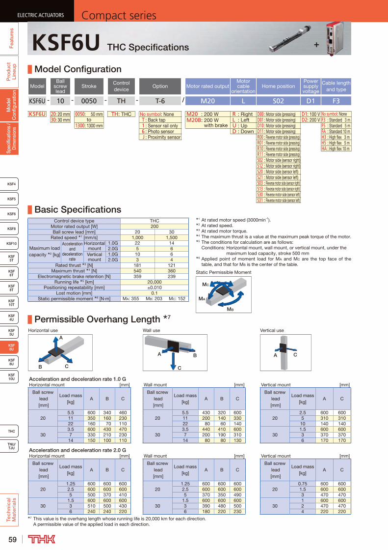
59
ELECTRIC ACTUATORS Compact seriesP
rod
uct
Line
upTe
ch
nic
al
Ma
teri
als
KSF8
KSF4
KSF 10T
KSF10
KSF 5T
KSF 6T
KSF 10U
KSF 4U
KSF 5U
KSF 8U
TNU/TJU
THC
Spec
ifica
tions
/ D
imen
sion
sM
odel
C
onfig
urat
ion
Fea
ture
sELECTRIC ACTUATORS Compact series
KSF5
KSF6
ELECTRIC ACTUATORS Compact series
KSF 6U
KSF8T
ELECTRIC ACTUATORS Compact series
KSF6U THC Specifications
Model Configuration
ModelBall
screw lead
StrokeControl device
Option Motor rated outputMotor cable
orientationHome position
Power supply voltage
Cable length and type
KSF6U - 10 - 0050 - TH - T-6 / M20 L S02 D1 F3
KSF6U 20: 20 mm 0050: 50 mm TH: THC No symbol: None M20 : 200 W R : Right D00 : Motor side (pressing) D1: 100 V No symbol: None30: 30 mm to T : Back tap M20B: 200 W
with brakeL : Left D01 : Motor side (pressing) D2: 200 V F3 : Standard 3 m
1300: 1300 mm 1 : Sensor rail only U : Up D10 : Motor side (pressing) F5 : Standard 5 m 6 : Photo sensor D : Down D11 : Motor side (pressing) FA : Standard 10 m J : Proximity sensor R00 : Reverse motor side (pressing) H3 : High flex 3 m
R01 : Reverse motor side (pressing) H5 : High flex 5 mR10 : Reverse motor side (pressing) HA : High flex 10 mR11 : Reverse motor side (pressing)S02 : Motor side (sensor right)S12 : Motor side (sensor right)S20 : Motor side (sensor left)S21 : Motor side (sensor left)S03 : Reverse motor side (sensor right)S13 : Reverse motor side (sensor right)S30 : Reverse motor side (sensor left)S31 : Reverse motor side (sensor left)
Basic SpecificationsControl device type THC
Motor rated output [W] 200Ball screw lead [mm] 20 30
Rated speed 1 [mm/s] 1,000 1,500
Maximum load capacity 2 [kg]
Acceleration and
deceleration rate
Horizontal mount
1.0G 22 142.0G 5 6
Vertical mount
1.0G 10 62.0G 3 4
Rated thrust 3 [N] 181 121Maximum thrust 4 [N] 540 360
Electromagnetic brake retention [N] 359 239Running life 5 [km] 20,000
Positioning repeatability [mm] ±0.010Lost motion [mm] 0.1
Static permissible moment 6 [N·m] MA: 355 MB: 203 MC: 152
Permissible Overhang Length 7
Horizontal use Wall use Vertical use
CB
A
A B
C
A C
Acceleration and deceleration rate 1.0 GHorizontal mount [mm] Wall mount [mm] Vertical mount [mm]
Ball screw lead [mm]
Load mass [kg]
A B CBall screw
lead [mm]
Load mass [kg]
A B CBall screw
lead [mm]
Load mass [kg]
A C
205.5 600 340 460
205.5 430 320 600
202.5 600 600
11 350 160 230 11 200 140 330 5 310 31022 160 70 110 22 80 60 140 10 140 140
303.5 600 430 470
303.5 440 410 600
301.5 600 600
7 330 210 230 7 200 190 310 3 370 37014 150 100 110 14 80 80 130 6 170 170
Acceleration and deceleration rate 2.0 GHorizontal mount [mm] Wall mount [mm] Vertical mount [mm]
Ball screw lead [mm]
Load mass [kg]
A B CBall screw
lead [mm]
Load mass [kg]
A B CBall screw
lead [mm]
Load mass [kg]
A C
201.25 600 600 600
201.25 600 600 600
200.75 600 600
2.5 600 600 600 2.5 600 600 600 1.5 600 6005 500 370 410 5 370 350 490 3 470 470
301.5 600 600 600
301.5 600 600 600
301 600 600
3 510 500 430 3 390 480 500 2 470 4706 240 240 220 6 180 220 230 4 220 220
7 This value is the overhang length whose running life is 20,000 km for each direction. A permissible value of the applied load in each direction.
MB
MA
MC
Static Permissible Moment
1 At rated motor speed (3000min-1).2 At rated speed.3 At rated motor torque.4 The maximum thrust is a value at the maximum peak torque of the motor.5 The conditions for calculation are as follows:
Conditions: Horizontal mount, wall mount, or vertical mount, under the maximum load capacity, stroke 500 mm
6 Applied point of moment load for MA and MC are the top face of the table, and that for MB is the center of the table.
+
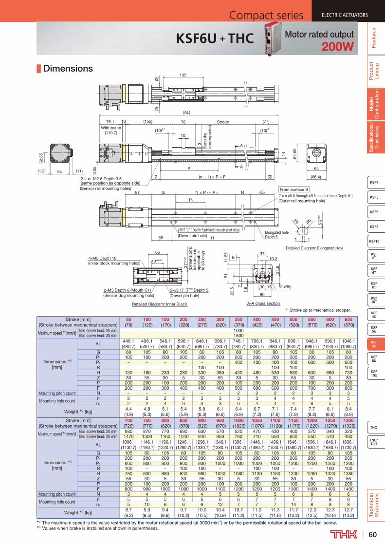
60
ELECTRIC ACTUATORSCompact series
Pro
duc
t Li
neup
Tec
hn
ica
l M
ate
ria
ls
THC
TNU/TJU
KSF8
KSF4
KSF 10T
KSF10
KSF 5T
KSF 6T
KSF 10U
KSF 4U
KSF 5U
KSF 8U
Spec
ifica
tions
/ D
imen
sion
sM
odel
C
onfig
urat
ion
Fea
ture
s
ELECTRIC ACTUATORSCompact series
KSF5
KSF6
ELECTRIC ACTUATORSCompact series
KSF 6U
KSF8T
ELECTRIC ACTUATORSCompact series
KSF6U + THC Motor rated output200W
Dimensions
Stroke [mm] (Stroke between mechanical stoppers)
50 (70)
100 (120)
150 (170)
200 (220)
250 (270)
300 (320)
350 (370)
400 (420)
450 (470)
500 (520)
550 (570)
600 (620)
650 (670)
Maximum speed 2 [mm/s] Ball screw lead: 20 mm 1000Ball screw lead: 30 mm 1500
Dimensions 3 [mm]
AL446.1 (480.7)
496.1 (530.7)
546.1 (580.7)
596.1 (630.7)
646.1 (680.7)
696.1 (730.7)
746.1 (780.7)
796.1 (830.7)
846.1 (880.7)
896.1 (930.7)
946.1 (980.7)
996.1 (1030.7)
1046.1 (1080.7)
G 80 105 80 105 80 105 80 105 80 105 80 105 80P1 100 100 200 200 200 200 200 200 200 200 200 200 200P2 − − − − − − 400 400 400 400 600 600 600R − − − − 100 100 − − 100 100 − − 100H 130 180 230 280 330 380 430 480 530 580 630 680 730Z 30 55 30 5 30 55 30 5 30 55 30 5 30P 200 200 100 200 200 200 100 200 200 200 100 200 200F 200 200 300 400 400 400 500 600 600 600 700 800 800
Mounting pitch count N − − − − − − 2 2 2 2 3 3 3
Mounting hole count n 2 2 2 2 3 3 3 3 4 4 4 4 5n1 2 2 4 3 3 3 6 4 4 4 8 5 5
Weight 3 [kg]4.4 (4.9)
4.8 (5.3)
5.1 (5.6)
5.4 (5.9)
5.8 (6.3)
6.1 (6.6)
6.4 (6.9)
6.7 (7.2)
7.1 (7.6)
7.4 (7.9)
7.7 (8.2)
8.1 (8.6)
8.4 (8.9)
Stroke [mm] (Stroke between mechanical stoppers)
700 (720)
750 (770)
800 (820)
850 (870)
900 (920)
950 (970)
1000 (1020)
1050 (1070)
1100 (1120)
1150 (1170)
1200 (1220)
1250 (1270)
1300 (1320)
Maximum speed 2 [mm/s] Ball screw lead: 20 mm 980 870 770 690 630 570 520 470 430 400 370 340 320Ball screw lead: 30 mm 1470 1300 1160 1040 940 850 780 710 650 600 550 510 480
Dimensions 3 [mm]
AL1096.1 (1130.7)
1146.1 (1180.7)
1196.1 (1230.7)
1246.1 (1280.7)
1296.1 (1330.7)
1346.1 (1380.7)
1396.1 (1430.7)
1446.1 (1480.7)
1496.1 (1530.7)
1546.1 (1580.7)
1596.1 (1630.7)
1646.1 (1680.7)
1696.1 (1730.7)
G 105 80 105 80 105 80 105 80 105 80 105 80 105P1 200 200 200 200 200 200 200 200 200 200 200 200 200P2 600 800 800 800 800 1000 1000 1000 1000 1200 1200 1200 1200R 100 − − 100 100 − − 100 100 − − 100 100H 780 830 880 930 980 1030 1080 1130 1180 1230 1280 1330 1380Z 55 30 5 30 55 30 5 30 55 30 5 30 55P 200 100 200 200 200 100 200 200 200 100 200 200 200F 800 900 1000 1000 1000 1100 1200 1200 1200 1300 1400 1400 1400
Mounting pitch count N 3 4 4 4 4 5 5 5 5 6 6 6 6
Mounting hole count n 5 5 5 6 6 6 6 7 7 7 7 8 8n1 5 10 6 6 6 12 7 7 7 14 8 8 8
Weight 3 [kg]8.7 (9.2)
9.0 (9.5)
9.4 (9.9)
9.7 (10.2)
10.0 (10.5)
10.4 (10.9)
10.7 (11.2)
11.0 (11.5)
11.3 (11.8)
11.7 (12.2)
12.0 (12.5)
12.3 (12.8)
12.7 (13.2)
2 The maximum speed is the value restricted by the motor rotational speed (at 3000 min-1) or by the permissible rotational speed of the ball screw.3 Values when brake is installed are shown in parentheses.
1 Stroke up to mechanical stopper.
Detailed Diagram: Elongated Hole
A
A
From surface B
2 × n- 5.5 through 9.5 counter bore Depth 5.1(Outer rail mounting hole)
N × P 1 = P 2 R (G)
62.8
5
64
5H7 + 0.012 Depth 5 (drilled through pilot hole) 0
(Dowel pin hole)
87
65 H
G
P1
Elongated hole Depth 5
1 1
5+0.
030
0(R)(R)
(66.4)(11)
32.8
5
(10) 1
(155) Stroke
(10) 1
78
P
2 × n1-M2.6 Depth 3.5 (same position as opposite side)(Sensor rail mounting holes)
Z (Z)
14
(n1 - 1) × P = F
3(S
enso
r dog
m
ount
ing su
rface
)
10
(77)
135
0.35
10
(AL)
76.1With brake
(110.7)
(2)
(2)
64(1.2)
Detailed Diagram: Inner Block A-A cross section
B
2-M3 Depth 6 (Mouth C1)(Sensor dog mounting hole)
4-M5 Depth 10(Inner block mounting holes)
2- 3H7 + 0.010 Depth 5 0
(Dowel pin hole)
27±
0.02
(Dim
ensi
onal
to
lera
nce
is
app
licab
le
to
3 on
ly)
40±0.02
65
30
51
37
23.5
11.8
5
10.2
1.97
60
24.8
15 2-(R6)
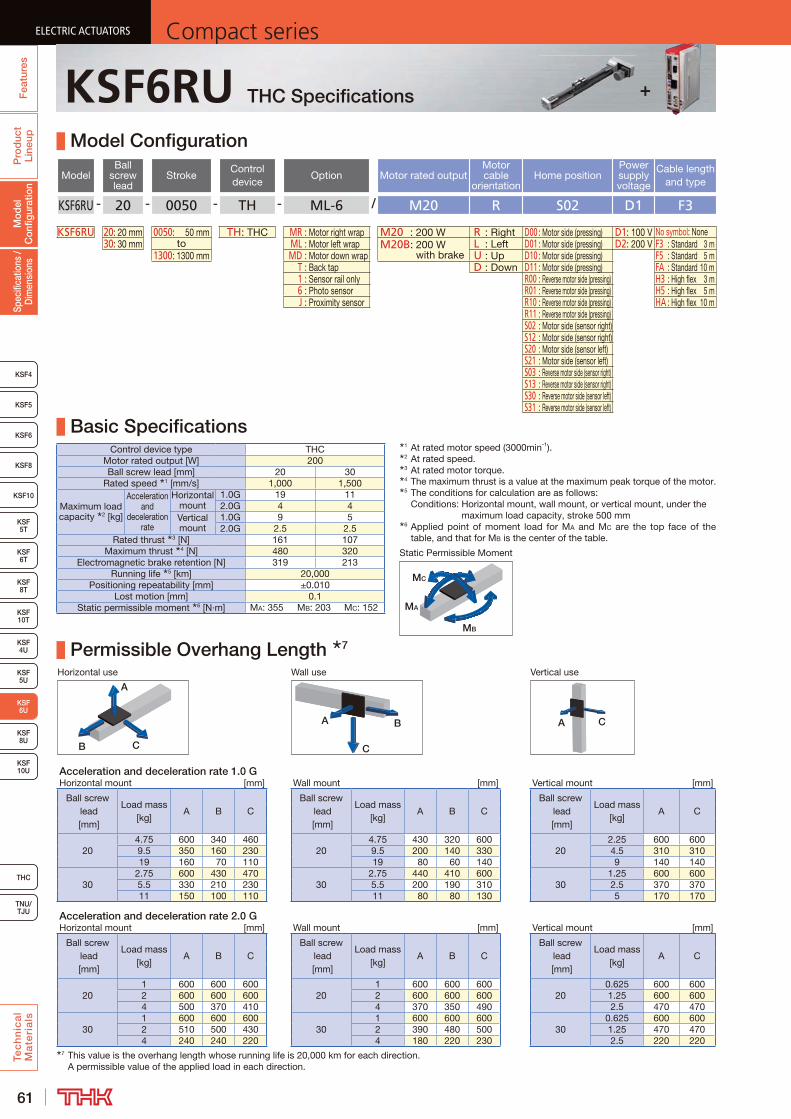
61
ELECTRIC ACTUATORS Compact seriesP
rod
uct
Line
upTe
ch
nic
al
Ma
teri
als
KSF8
KSF4
KSF 10T
KSF10
KSF 5T
KSF 6T
KSF 10U
KSF 4U
KSF 5U
KSF 8U
TNU/TJU
THC
Spec
ifica
tions
/ D
imen
sion
sM
odel
C
onfig
urat
ion
Fea
ture
sELECTRIC ACTUATORS Compact series
KSF5
KSF6
ELECTRIC ACTUATORS Compact series
KSF 6U
KSF8T
ELECTRIC ACTUATORS Compact series
KSF6RU THC Specifications
Model Configuration
ModelBall
screw lead
StrokeControl device
Option Motor rated outputMotor cable
orientationHome position
Power supply voltage
Cable length and type
KSF6RU - 20 - 0050 - TH - ML-6 / M20 R S02 D1 F3
KSF6RU 20: 20 mm 0050: 50 mm TH: THC MR : Motor right wrap M20 : 200 W R : Right D00 : Motor side (pressing) D1: 100 V No symbol: None30: 30 mm to ML : Motor left wrap M20B: 200 W
with brakeL : Left D01 : Motor side (pressing) D2: 200 V F3 : Standard 3 m
1300: 1300 mm MD : Motor down wrap U : Up D10 : Motor side (pressing) F5 : Standard 5 m T : Back tap D : Down D11 : Motor side (pressing) FA : Standard 10 m 1 : Sensor rail only R00 : Reverse motor side (pressing) H3 : High flex 3 m 6 : Photo sensor R01 : Reverse motor side (pressing) H5 : High flex 5 m J : Proximity sensor R10 : Reverse motor side (pressing) HA : High flex 10 m
R11 : Reverse motor side (pressing)S02 : Motor side (sensor right)S12 : Motor side (sensor right)S20 : Motor side (sensor left)S21 : Motor side (sensor left)S03 : Reverse motor side (sensor right)S13 : Reverse motor side (sensor right)S30 : Reverse motor side (sensor left)S31 : Reverse motor side (sensor left)
Basic SpecificationsControl device type THC
Motor rated output [W] 200Ball screw lead [mm] 20 30
Rated speed 1 [mm/s] 1,000 1,500
Maximum load capacity 2 [kg]
Acceleration and
deceleration rate
Horizontal mount
1.0G 19 112.0G 4 4
Vertical mount
1.0G 9 52.0G 2.5 2.5
Rated thrust 3 [N] 161 107Maximum thrust 4 [N] 480 320
Electromagnetic brake retention [N] 319 213Running life 5 [km] 20,000
Positioning repeatability [mm] ±0.010Lost motion [mm] 0.1
Static permissible moment 6 [N·m] MA: 355 MB: 203 MC: 152
Permissible Overhang Length 7
Horizontal use Wall use Vertical use
CB
A
A B
C
A C
Acceleration and deceleration rate 1.0 GHorizontal mount [mm] Wall mount [mm] Vertical mount [mm]
Ball screw lead [mm]
Load mass [kg]
A B CBall screw
lead [mm]
Load mass [kg]
A B CBall screw
lead [mm]
Load mass [kg]
A C
204.75 600 340 460
204.75 430 320 600
202.25 600 600
9.5 350 160 230 9.5 200 140 330 4.5 310 31019 160 70 110 19 80 60 140 9 140 140
302.75 600 430 470
302.75 440 410 600
301.25 600 600
5.5 330 210 230 5.5 200 190 310 2.5 370 37011 150 100 110 11 80 80 130 5 170 170
Acceleration and deceleration rate 2.0 GHorizontal mount [mm] Wall mount [mm] Vertical mount [mm]
Ball screw lead [mm]
Load mass [kg]
A B CBall screw
lead [mm]
Load mass [kg]
A B CBall screw
lead [mm]
Load mass [kg]
A C
201 600 600 600
201 600 600 600
200.625 600 600
2 600 600 600 2 600 600 600 1.25 600 6004 500 370 410 4 370 350 490 2.5 470 470
301 600 600 600
301 600 600 600
300.625 600 600
2 510 500 430 2 390 480 500 1.25 470 4704 240 240 220 4 180 220 230 2.5 220 220
7 This value is the overhang length whose running life is 20,000 km for each direction. A permissible value of the applied load in each direction.
MB
MA
MC
Static Permissible Moment
1 At rated motor speed (3000min-1).2 At rated speed.3 At rated motor torque.4 The maximum thrust is a value at the maximum peak torque of the motor.5 The conditions for calculation are as follows:
Conditions: Horizontal mount, wall mount, or vertical mount, under the maximum load capacity, stroke 500 mm
6 Applied point of moment load for MA and MC are the top face of the table, and that for MB is the center of the table.
+
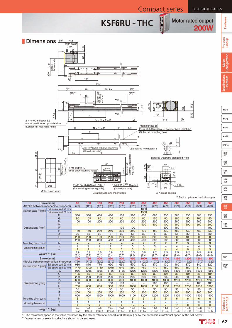
62
ELECTRIC ACTUATORSCompact series
Pro
duc
t Li
neup
Tec
hn
ica
l M
ate
ria
ls
THC
TNU/TJU
KSF8
KSF4
KSF 10T
KSF10
KSF 5T
KSF 6T
KSF 10U
KSF 4U
KSF 5U
KSF 8U
Spec
ifica
tions
/ D
imen
sion
sM
odel
C
onfig
urat
ion
Fea
ture
s
ELECTRIC ACTUATORSCompact series
KSF5
KSF6
ELECTRIC ACTUATORSCompact series
KSF 6U
KSF8T
ELECTRIC ACTUATORSCompact series
KSF6RU + THC Motor rated output200W
Dimensions
Stroke [mm] (Stroke between mechanical stoppers)
50 (70)
100 (120)
150 (170)
200 (220)
250 (270)
300 (320)
350 (370)
400 (420)
450 (470)
500 (520)
550 (570)
600 (620)
650 (670)
Maximum speed 2 [mm/s] Ball screw lead: 20 mm 1000Ball screw lead: 30 mm 1500
Dimensions [mm]
AL 336 386 436 486 536 586 636 686 736 786 836 886 936G 80 105 80 105 80 105 80 105 80 105 80 105 80P1 100 100 200 200 200 200 200 200 200 200 200 200 200P2 − − − − − − 400 400 400 400 600 600 600R − − − − 100 100 − − 100 100 − − 100H 130 180 230 280 330 380 430 480 530 580 630 680 730Z 30 55 30 5 30 55 30 5 30 55 30 5 30P 200 200 100 200 200 200 100 200 200 200 100 200 200F 200 200 300 400 400 400 500 600 600 600 700 800 800
Mounting pitch count N − − − − − − 2 2 2 2 3 3 3
Mounting hole count n 2 2 2 2 3 3 3 3 4 4 4 4 5n1 2 2 4 3 3 3 6 4 4 4 8 5 5
Weight 3 [kg] 4.9 (5.4)
5.2 (5.7)
5.6 (6.1)
5.9 (6.4)
6.2 (6.7)
6.5 (7.0)
6.9 (7.4)
7.2 (7.7)
7.5 (8.0)
7.9 (8.4)
8.2 (8.7)
8.5 (9.0)
8.9 (9.4)
Stroke [mm] (Stroke between mechanical stoppers)
700 (720)
750 (770)
800 (820)
850 (870)
900 (920)
950 (970)
1000 (1020)
1050 (1070)
1100 (1120)
1150 (1170)
1200 (1220)
1250 (1270)
1300 (1320)
Maximum speed 2 [mm/s] Ball screw lead: 20 mm 980 870 770 690 630 570 520 470 430 400 370 340 320Ball screw lead: 30 mm 1470 1300 1160 1040 940 850 780 710 650 600 550 510 480
Dimensions [mm]
AL 986 1036 1086 1136 1186 1236 1286 1336 1386 1436 1486 1536 1586G 105 80 105 80 105 80 105 80 105 80 105 80 105P1 200 200 200 200 200 200 200 200 200 200 200 200 200P2 600 800 800 800 800 1000 1000 1000 1000 1200 1200 1200 1200R 100 − − 100 100 − − 100 100 − − 100 100H 780 830 880 930 980 1030 1080 1130 1180 1230 1280 1330 1380Z 55 30 5 30 55 30 5 30 55 30 5 30 55P 200 100 200 200 200 100 200 200 200 100 200 200 200F 800 900 1000 1000 1000 1100 1200 1200 1200 1300 1400 1400 1400
Mounting pitch count N 3 4 4 4 4 5 5 5 5 6 6 6 6
Mounting hole count n 5 5 5 6 6 6 6 7 7 7 7 8 8n1 5 10 6 6 6 12 7 7 7 14 8 8 8
Weight 3 [kg] 9.2 (9.7)
9.5 (10.0)
9.8 (10.3)
10.2 (10.7)
10.5 (11.0)
10.8 (11.3)
11.2 (11.7)
11.5 (12.0)
11.8 (12.3)
12.1 (12.6)
12.5 (13.0)
12.8 (13.3)
13.1 (13.6)
2 The maximum speed is the value restricted by the motor rotational speed (at 3000 min-1) or by the permissible rotational speed of the ball screw.3 Values when brake is installed are shown in parentheses.
(13)
(40) 76.1With brake
(110.7)(2
9)(7
5)(D
istan
ce
betw
een s
hafts
)
□60
(2)
(AL)
135
(10) 1 (10) 1
(77)Stroke(131) 78
A10
3
0.35
(Sensor rail mounting holes)
A
Z
P
(n1 - 1) × P = F
N × P1 = P2
(Z)
RG (G)From surface B2 × n- 5.5 through 9.5 counter bore Depth 5.1(Outer rail mounting hole)P1
(Dowel pin hole)H65
Elongated hole Depth 5Depth 5 (drilled through pilot hole) 0+0.012
Detailed Diagram: Elongated Hole
1
(R)
1
5+
0.03
0 0(R)
30
(2.8
)
(2)
(60)
14
148
64
62.8
5
(Sen
sor d
og
mou
ntin
g su
rface
)
2 × n1-M2.6 Depth 3.5 (same position as opposite side)
65
40±0.024-M5 Depth 10(Inner block mounting holes)
2-M3 Depth 6 (Mouth C1)(Sensor dog mounting hole)
+0.010 0 Depth 5
(Dowel pin hole)2- 3H7
27±
0.02
(Dim
ensi
onal
to
lera
nce
is a
pplic
able
to
3
only
)
5123
.511
.85
1.97
3710.2
24.8
30
60
15 2-(R6)
A-A cross sectionDetailed Diagram: Inner Block
B
1 Stroke up to mechanical stopper.
5H7
Motor down wrap
(83.
2)
(1.7
)(2
)14
5
(60)
(Dis
tanc
e b
etw
een
shaf
ts)
(75)
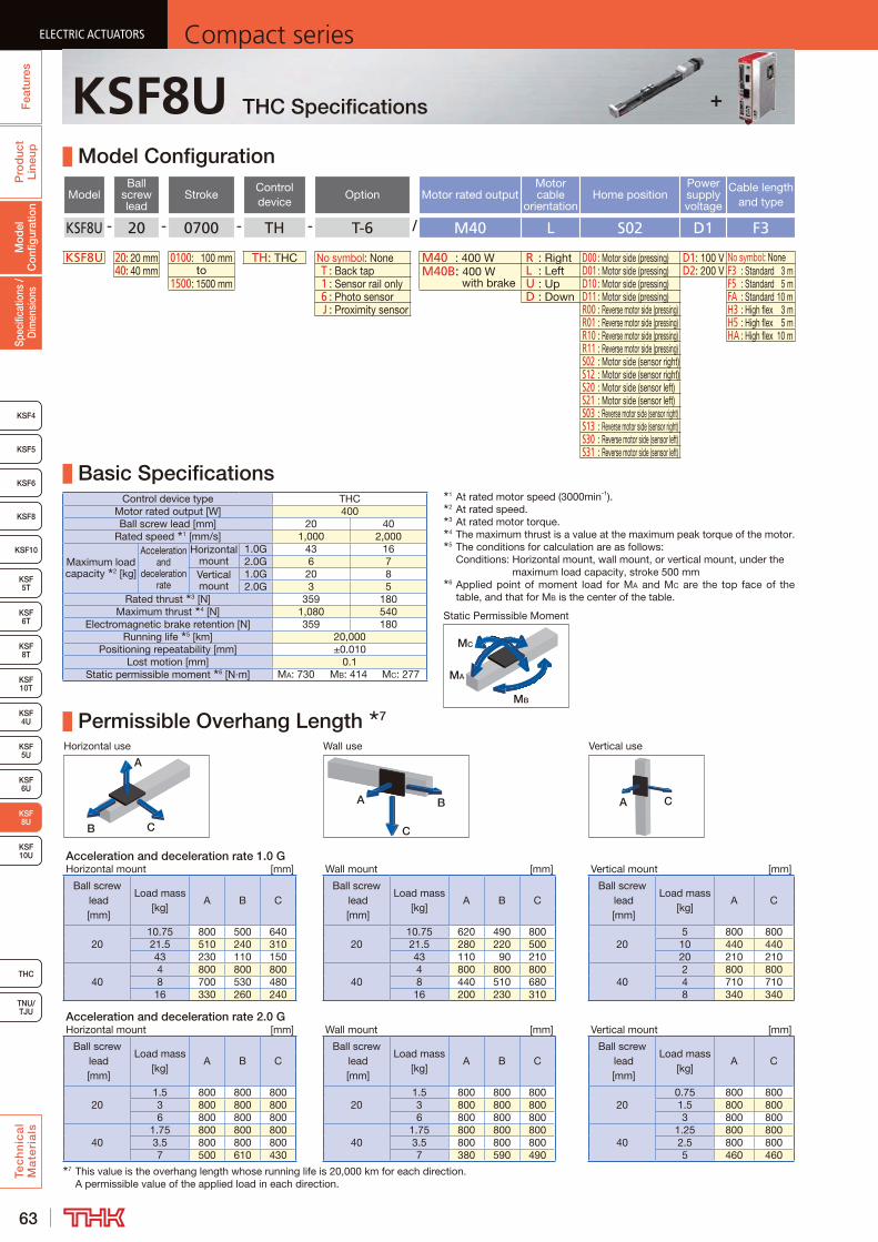
63
ELECTRIC ACTUATORS Compact seriesP
rod
uct
Line
upTe
ch
nic
al
Ma
teri
als
KSF8
KSF4
KSF 10T
KSF10
KSF 5T
KSF 6T
KSF 8T
KSF 10U
KSF 4U
KSF 6U
TNU/TJU
THC
Spec
ifica
tions
/ D
imen
sion
sM
odel
C
onfig
urat
ion
Fea
ture
sELECTRIC ACTUATORS Compact series
KSF5
KSF6
ELECTRIC ACTUATORS Compact series
KSF 8U
KSF 5U
ELECTRIC ACTUATORS Compact series
KSF8U THC Specifications
Model Configuration
ModelBall
screw lead
StrokeControl device
Option Motor rated outputMotor cable
orientationHome position
Power supply voltage
Cable length and type
KSF8U - 20 - 0700 - TH - T-6 / M40 L S02 D1 F3
KSF8U 20: 20 mm 0100: 100 mm TH: THC No symbol: None M40 : 400 W R : Right D00 : Motor side (pressing) D1: 100 V No symbol: None40: 40 mm to T : Back tap M40B: 400 W
with brakeL : Left D01 : Motor side (pressing) D2: 200 V F3 : Standard 3 m
1500: 1500 mm 1 : Sensor rail only U : Up D10 : Motor side (pressing) F5 : Standard 5 m 6 : Photo sensor D : Down D11 : Motor side (pressing) FA : Standard 10 m J : Proximity sensor R00 : Reverse motor side (pressing) H3 : High flex 3 m
R01 : Reverse motor side (pressing) H5 : High flex 5 mR10 : Reverse motor side (pressing) HA : High flex 10 mR11 : Reverse motor side (pressing)S02 : Motor side (sensor right)S12 : Motor side (sensor right)S20 : Motor side (sensor left)S21 : Motor side (sensor left)S03 : Reverse motor side (sensor right)S13 : Reverse motor side (sensor right)S30 : Reverse motor side (sensor left)S31 : Reverse motor side (sensor left)
Basic SpecificationsControl device type THC
Motor rated output [W] 400Ball screw lead [mm] 20 40
Rated speed 1 [mm/s] 1,000 2,000
Maximum load capacity 2 [kg]
Acceleration and
deceleration rate
Horizontal mount
1.0G 43 162.0G 6 7
Vertical mount
1.0G 20 82.0G 3 5
Rated thrust 3 [N] 359 180Maximum thrust 4 [N] 1,080 540
Electromagnetic brake retention [N] 359 180Running life 5 [km] 20,000
Positioning repeatability [mm] ±0.010Lost motion [mm] 0.1
Static permissible moment 6 [N·m] MA: 730 MB: 414 MC: 277
Permissible Overhang Length 7
Horizontal use Wall use Vertical use
CB
A
A B
C
A C
Acceleration and deceleration rate 1.0 GHorizontal mount [mm] Wall mount [mm] Vertical mount [mm]
Ball screw lead [mm]
Load mass [kg]
A B CBall screw
lead [mm]
Load mass [kg]
A B CBall screw
lead [mm]
Load mass [kg]
A C
2010.75 800 500 640
2010.75 620 490 800
205 800 800
21.5 510 240 310 21.5 280 220 500 10 440 44043 230 110 150 43 110 90 210 20 210 210
404 800 800 800
404 800 800 800
402 800 800
8 700 530 480 8 440 510 680 4 710 71016 330 260 240 16 200 230 310 8 340 340
Acceleration and deceleration rate 2.0 GHorizontal mount [mm] Wall mount [mm] Vertical mount [mm]
Ball screw lead [mm]
Load mass [kg]
A B CBall screw
lead [mm]
Load mass [kg]
A B CBall screw
lead [mm]
Load mass [kg]
A C
201.5 800 800 800
201.5 800 800 800
200.75 800 800
3 800 800 800 3 800 800 800 1.5 800 8006 800 800 800 6 800 800 800 3 800 800
401.75 800 800 800
401.75 800 800 800
401.25 800 800
3.5 800 800 800 3.5 800 800 800 2.5 800 8007 500 610 430 7 380 590 490 5 460 460
7 This value is the overhang length whose running life is 20,000 km for each direction. A permissible value of the applied load in each direction.
MB
MA
MC
Static Permissible Moment
1 At rated motor speed (3000min-1).2 At rated speed.3 At rated motor torque.4 The maximum thrust is a value at the maximum peak torque of the motor.5 The conditions for calculation are as follows:
Conditions: Horizontal mount, wall mount, or vertical mount, under the maximum load capacity, stroke 500 mm
6 Applied point of moment load for MA and MC are the top face of the table, and that for MB is the center of the table.
+

64
ELECTRIC ACTUATORSCompact series
Pro
duc
t Li
neup
Tec
hn
ica
l M
ate
ria
ls
THC
TNU/TJU
KSF8
KSF4
KSF 10T
KSF10
KSF 5T
KSF 6T
KSF 8T
KSF 10U
KSF 4U
KSF 6U
Spec
ifica
tions
/ D
imen
sion
sM
odel
C
onfig
urat
ion
Fea
ture
s
ELECTRIC ACTUATORSCompact series
KSF5
KSF6
ELECTRIC ACTUATORSCompact series
KSF 8U
KSF 5U
ELECTRIC ACTUATORSCompact series
KSF8U + THC Motor rated output400W
Dimensions
Stroke [mm] (Stroke between mechanical stoppers)
100 (120)
200 (220)
300 (320)
400 (420)
500 (520)
600 (620)
700 (720)
800 (820)
900 (920)
1000 (1020)
1100 (1120)
1200 (1220)
1300 (1320)
1400 (1420)
1500 (1520)
Maximum speed 2 [mm/s]
Ball screw lead: 20 mm 1000 970 790 660 550 470 410 360 320Ball screw lead: 40 mm 2000 1940 1580 1320 1110 950 830 720 640
Dimensions 3 [mm]
AL586.1 (620.7)
686.1 (720.7)
786.1 (820.7)
886.1 (920.7)
986.1 (1020.7)
1086.1 (1120.7)
1186.1 (1220.7)
1286.1 (1320.7)
1386.1 (1420.7)
1486.1 (1520.7)
1586.1 (1620.7)
1686.1 (1720.7)
1786.1 (1820.7)
1886.1 (1920.7)
1986.1 (2020.7)
G 85 135 85 135 85 135 85 135 85 135 85 135 85 135 85H 300 400 500 600 700 800 900 1000 1100 1200 1300 1400 1500 1600 1700Z 85 35 85 35 85 35 85 35 85 35 85 35 85 35 85F 200 400 400 600 600 800 800 1000 1000 1200 1200 1400 1400 1600 1600
Mounting pitch count N 1 1 2 2 3 3 4 4 5 5 6 6 7 7 8Mounting hole
countn 2 2 3 3 4 4 5 5 6 6 7 7 8 8 9n1 2 3 3 4 4 5 5 6 6 7 7 8 8 9 9
Weight 3 [kg]8.8 (9.3)
10.0 (10.5)
11.1 (11.6)
12.3 (12.8)
13.5 (14.0)
14.7 (15.2)
15.8 (16.3)
17.0 (17.5)
18.2 (18.7)
19.4 (19.9)
20.5 (21.0)
21.7 (22.2)
22.9 (23.4)
24.0 (24.5)
25.2 (25.7)
2 The maximum speed is the value restricted by the motor rotational speed (at 3000 min-1) or by the permissible rotational speed of the ball screw.3 Values when brake is installed are shown in parentheses.
1 Stroke up to mechanical stopper.
Detailed Diagram: Elongated HoleDetailed Diagram: Inner Block
A
A
A-A cross section
B
2- 5H7 + 0.012 Depth 10 0
(Dowel pin hole)
4-M3 Depth 6 (Mouth C1)(Sensor dog mounting hole)
38±
0.02
(Dim
ensi
onal
tole
ranc
e is
ap
plic
able
to
5 on
ly)
2 × n1-M2.6 Depth 3.5 (same position as opposite side)(Sensor rail mounting holes)
Stroke120
200
(G)
100
11
(R) (R) 5+
0.03
0 0
93
35 H
67.3
N × 200
Elongated hole Depth 55H7 + 0.012 Depth 5 (drilled through pilot hole) 0
(Dowel pin hole)
Z
G
(10) 1
(168)
4-M6 Depth 12(Inner block mounting holes)
From surface B2 × n- 6.6 through 11 counter bore Depth 6.3
(Outer rail mounting hole)
70±0.02
(90)
(Z)(n1-1) × 200 = F
200 84
10
2(S
enso
r dog
m
ount
ing
surf
ace)
1
193
19
10
98.1With brake
(132.7)
(AL)
(1)84(1.2)
37
(86.4)
(2)
(2)
3.7
10
589.
3
17
32
52
46
31.2
16
802-(R6)
(10) 1
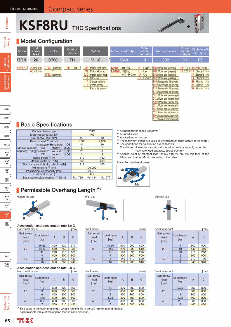
65
ELECTRIC ACTUATORS Compact seriesP
rod
uct
Line
upTe
ch
nic
al
Ma
teri
als
KSF8
KSF4
KSF 10T
KSF10
KSF 5T
KSF 6T
KSF 8T
KSF 10U
KSF 4U
KSF 6U
TNU/TJU
THC
Spec
ifica
tions
/ D
imen
sion
sM
odel
C
onfig
urat
ion
Fea
ture
sELECTRIC ACTUATORS Compact series
KSF5
KSF6
ELECTRIC ACTUATORS Compact series
KSF 8U
KSF 5U
ELECTRIC ACTUATORS Compact series
KSF8RU THC Specifications
Model Configuration
ModelBall
screw lead
StrokeControl device
Option Motor rated outputMotor cable
orientationHome position
Power supply voltage
Cable length and type
KSF8RU - 20 - 0700 - TH - ML-6 / M40 R S02 D1 F3
KSF8RU 20: 20 mm 0100: 100 mm TH: THC MR : Motor right wrap M40 : 400 W R : Right D00 : Motor side (pressing) D1: 100 V No symbol: None40: 40 mm to ML : Motor left wrap M40B: 400 W
with brakeL : Left D01 : Motor side (pressing) D2: 200 V F3 : Standard 3 m
1500: 1500 mm MD : Motor down wrap U : Up D10 : Motor side (pressing) F5 : Standard 5 m T : Back tap D : Down D11 : Motor side (pressing) FA : Standard 10 m 1 : Sensor rail only R00 : Reverse motor side (pressing) H3 : High flex 3 m 6 : Photo sensor R01 : Reverse motor side (pressing) H5 : High flex 5 m J : Proximity sensor R10 : Reverse motor side (pressing) HA : High flex 10 m
R11 : Reverse motor side (pressing)S02 : Motor side (sensor right)S12 : Motor side (sensor right)S20 : Motor side (sensor left)S21 : Motor side (sensor left)S03 : Reverse motor side (sensor right)S13 : Reverse motor side (sensor right)S30 : Reverse motor side (sensor left)S31 : Reverse motor side (sensor left)
Basic SpecificationsControl device type THC
Motor rated output [W] 400Ball screw lead [mm] 20 40
Rated speed 1 [mm/s] 1,000 2,000
Maximum load capacity 2 [kg]
Acceleration and
deceleration rate
Horizontal mount
1.0G 41 162.0G 6 7
Vertical mount
1.0G 20 82.0G 3 5
Rated thrust 3 [N] 319 160Maximum thrust 4 [N] 960 480
Electromagnetic brake retention [N] 319 160Running life 5 [km] 20,000
Positioning repeatability [mm] ±0.010Lost motion [mm] 0.1
Static permissible moment 6 [N·m] MA: 730 MB: 414 MC: 277
Permissible Overhang Length 7
Horizontal use Wall use Vertical use
CB
A
A B
C
A C
Acceleration and deceleration rate 1.0 GHorizontal mount [mm] Wall mount [mm] Vertical mount [mm]
Ball screw lead [mm]
Load mass [kg]
A B CBall screw
lead [mm]
Load mass [kg]
A B CBall screw
lead [mm]
Load mass [kg]
A C
2010.25 800 520 670
2010.25 630 500 800
205 800 800
20.5 540 250 330 20.5 290 230 510 10 440 44041 240 110 160 41 120 90 220 20 210 210
404 800 800 800
404 800 800 800
402 800 800
8 700 530 480 8 440 510 680 4 710 71016 330 260 240 16 200 230 310 8 340 340
Acceleration and deceleration rate 2.0 GHorizontal mount [mm] Wall mount [mm] Vertical mount [mm]
Ball screw lead [mm]
Load mass [kg]
A B CBall screw
lead [mm]
Load mass [kg]
A B CBall screw
lead [mm]
Load mass [kg]
A C
201.5 800 800 800
201.5 800 800 800
200.75 800 800
3 800 800 800 3 800 800 800 1.5 800 8006 800 800 800 6 800 800 800 3 800 800
401.75 800 800 800
401.75 800 800 800
401.25 800 800
3.5 800 800 800 3.5 800 800 800 2.5 800 8007 500 610 430 7 380 590 490 5 460 460
7 This value is the overhang length whose running life is 20,000 km for each direction. A permissible value of the applied load in each direction.
MB
MA
MC
Static Permissible Moment
1 At rated motor speed (3000min-1).2 At rated speed.3 At rated motor torque.4 The maximum thrust is a value at the maximum peak torque of the motor.5 The conditions for calculation are as follows:
Conditions: Horizontal mount, wall mount, or vertical mount, under the maximum load capacity, stroke 500 mm
6 Applied point of moment load for MA and MC are the top face of the table, and that for MB is the center of the table.
+
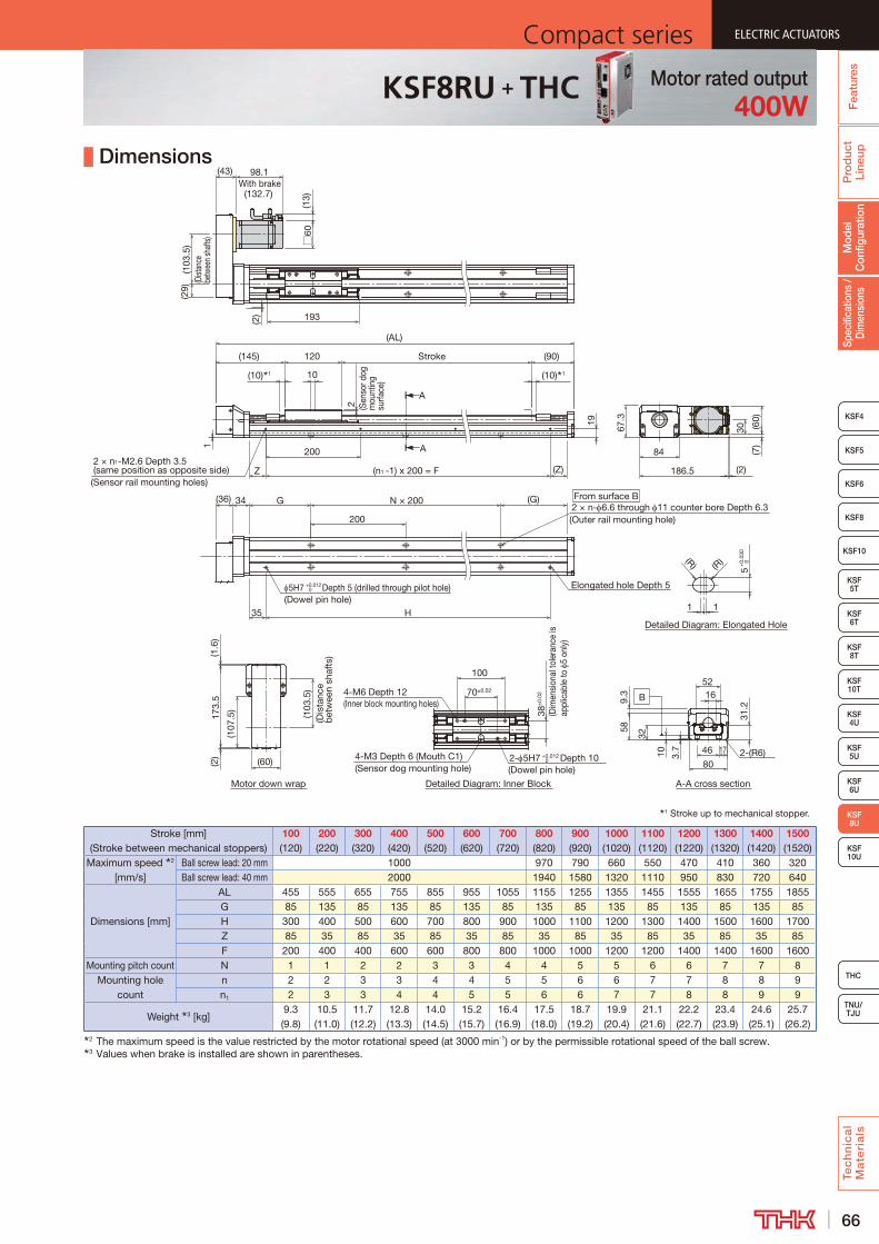
66
ELECTRIC ACTUATORSCompact series
Pro
duc
t Li
neup
Tec
hn
ica
l M
ate
ria
ls
THC
TNU/TJU
KSF8
KSF4
KSF 10T
KSF10
KSF 5T
KSF 6T
KSF 8T
KSF 10U
KSF 4U
KSF 6U
Spec
ifica
tions
/ D
imen
sion
sM
odel
C
onfig
urat
ion
Fea
ture
s
ELECTRIC ACTUATORSCompact series
KSF5
KSF6
ELECTRIC ACTUATORSCompact series
KSF 8U
KSF 5U
ELECTRIC ACTUATORSCompact series
KSF8RU + THC Motor rated output400W
Dimensions
Stroke [mm] (Stroke between mechanical stoppers)
100 (120)
200 (220)
300 (320)
400 (420)
500 (520)
600 (620)
700 (720)
800 (820)
900 (920)
1000 (1020)
1100 (1120)
1200 (1220)
1300 (1320)
1400 (1420)
1500 (1520)
Maximum speed 2 [mm/s]
Ball screw lead: 20 mm 1000 970 790 660 550 470 410 360 320Ball screw lead: 40 mm 2000 1940 1580 1320 1110 950 830 720 640
Dimensions [mm]
AL 455 555 655 755 855 955 1055 1155 1255 1355 1455 1555 1655 1755 1855G 85 135 85 135 85 135 85 135 85 135 85 135 85 135 85H 300 400 500 600 700 800 900 1000 1100 1200 1300 1400 1500 1600 1700Z 85 35 85 35 85 35 85 35 85 35 85 35 85 35 85F 200 400 400 600 600 800 800 1000 1000 1200 1200 1400 1400 1600 1600
Mounting pitch count N 1 1 2 2 3 3 4 4 5 5 6 6 7 7 8Mounting hole
countn 2 2 3 3 4 4 5 5 6 6 7 7 8 8 9n1 2 3 3 4 4 5 5 6 6 7 7 8 8 9 9
Weight 3 [kg]9.3 (9.8)
10.5 (11.0)
11.7 (12.2)
12.8 (13.3)
14.0 (14.5)
15.2 (15.7)
16.4 (16.9)
17.5 (18.0)
18.7 (19.2)
19.9 (20.4)
21.1 (21.6)
22.2 (22.7)
23.4 (23.9)
24.6 (25.1)
25.7 (26.2)
2 The maximum speed is the value restricted by the motor rotational speed (at 3000 min-1) or by the permissible rotational speed of the ball screw.3 Values when brake is installed are shown in parentheses.
1 Stroke up to mechanical stopper.
Detailed Diagram: Inner Block
Detailed Diagram: Elongated Hole
A
A
Motor down wrap A-A cross section
B
19
1
2 (Sen
sor d
og
mou
ntin
g su
rface
)
2 × n1-M2.6 Depth 3.5 (same position as opposite side)
(Sensor rail mounting holes)
200
(n1 -1) x 200 = F (Z)Z
200
(G)
35 H
N × 200
Elongated hole Depth 55H7 +0.012 0 Depth 5 (drilled through pilot hole)
(Dowel pin hole)
G From surface B2 × n- 6.6 through 11 counter bore Depth 6.3(Outer rail mounting hole)
(36) 34
2- 5H7 +0.012 0 Depth 10
(Dowel pin hole)4-M3 Depth 6 (Mouth C1)(Sensor dog mounting hole)
38±
0.02
100
4-M6 Depth 12(Inner block mounting holes)
70±0.02
11
(R) (R)
5+
0.03
0 0
(AL)
(10) 1 (10) 1
(90)Stroke
10
120
(2)
(145)
193
84
(60)
30
(7)
186.5
67.3
(2)
(29)
(103
.5)
(Dist
ance
be
twee
n sha
fts)
173.
5
(107
.5)
(1.6
)
(103
.5)
(Dis
tanc
e b
etw
een
shaf
ts)
(2)
(43) 98.1With brake
(132.7)
□60
(13)
3.7
10
589.
3
17
32
52
4631
.2
16
802-(R6)
(60)
(Dim
ensi
onal
tole
ranc
e is
ap
plic
able
to
5 on
ly)

67
ELECTRIC ACTUATORS Compact seriesP
rod
uct
Line
upTe
ch
nic
al
Ma
teri
als
KSF8
KSF4
KSF 10T
KSF10
KSF 5T
KSF 6T
KSF 8T
KSF 4U
KSF 5U
KSF 6U
KSF 8U
TNU/TJU
THC
Spec
ifica
tions
/ D
imen
sion
sM
odel
C
onfig
urat
ion
Fea
ture
sELECTRIC ACTUATORS Compact series
KSF5
KSF6
ELECTRIC ACTUATORS Compact series
KSF 10U
ELECTRIC ACTUATORS Compact series
KSF10U THC Specifications
Model Configuration
ModelBall
screw lead
StrokeControl device
Option Motor rated outputMotor cable
orientationHome position
Power supply voltage
Cable length and type
KSF10U - 25 - 0700 - TH - T-6 / M75 L S02 D2 F3
KSF10U 25: 25 mm 0100: 100 mm TH: THC No symbol: None M75 : 750 W R : Right D00 : Motor side (pressing) D2: 200 V No symbol: None50: 50 mm to T : Back tap M75B: 750 W
with brakeL : Left D01 : Motor side (pressing) F3 : Fixed 3 m
1500: 1500 mm 1 : Sensor rail only U : Up D10 : Motor side (pressing) F5 : Fixed 5 m 6 : Photo sensor D : Down D11 : Motor side (pressing) FA : Standard 10 m J : Proximity sensor R00 : Reverse motor side (pressing) H3 : High flex 3 m
R01 : Reverse motor side (pressing) H5 : High flex 5 mR10 : Reverse motor side (pressing) HA : High flex 10 mR11 : Reverse motor side (pressing)S02 : Motor side (sensor right)S12 : Motor side (sensor right)S20 : Motor side (sensor left)S21 : Motor side (sensor left)S03 : Reverse motor side (sensor right)S13 : Reverse motor side (sensor right)S30 : Reverse motor side (sensor left)S31 : Reverse motor side (sensor left)
Basic SpecificationsControl device type THC
Motor rated output [W] 750Ball screw lead [mm] 25 50
Rated speed 1 [mm/s] 1,250 2,500
Maximum load capacity 2 [kg]
Acceleration and
deceleration rate
Horizontal mount
1.0G 60 171.5G 26 8
Vertical mount
1.0G 25 91.5G 13 5
Rated thrust 3 [N] 541 270Maximum thrust 4 [N] 1,620 810
Electromagnetic brake retention [N] 541 270Running life 5 [km] 20,000
Positioning repeatability [mm] ±0.010Lost motion [mm] 0.1
Static permissible moment 6 [N·m] MA: 1,259 MB: 775 MC: 504
Permissible Overhang Length 7
Horizontal use Wall use Vertical use
CB
A
A B
C
A C
Acceleration and deceleration rate 1.0 GHorizontal mount [mm] Wall mount [mm] Vertical mount [mm]
Ball screw lead [mm]
Load mass [kg]
A B CBall screw
lead [mm]
Load mass [kg]
A B CBall screw
lead [mm]
Load mass [kg]
A C
2515 1000 760 900
2515 860 740 1000
256.25 1000 1000
30 680 370 440 30 400 350 650 12.5 730 73060 320 170 220 60 170 150 290 25 350 350
504.25 1000 1000 1000
504.25 1000 1000 1000
502.25 1000 1000
8.5 1000 1000 840 8.5 810 1000 1000 4.5 1000 100017 600 530 420 17 380 500 570 9 960 960
Acceleration and deceleration rate 1.5 GHorizontal mount [mm] Wall mount [mm] Vertical mount [mm]
Ball screw lead [mm]
Load mass [kg]
A B CBall screw
lead [mm]
Load mass [kg]
A B CBall screw
lead [mm]
Load mass [kg]
A C
256.5 1000 1000 1000
256.5 1000 1000 1000
253.25 1000 1000
13 1000 880 910 13 870 860 1000 6.5 1000 100026 600 430 460 26 410 400 580 13 650 650
502 1000 1000 1000
502 1000 1000 1000
501.25 1000 1000
4 1000 1000 1000 4 1000 1000 1000 2.5 1000 10008 1000 1000 780 8 730 1000 990 5 970 970
7 This value is the overhang length whose running life is 20,000 km for each direction. A permissible value of the applied load in each direction.
MB
MA
MC
Static Permissible Moment
1 At rated motor speed (3000min-1).2 At rated speed.3 At rated motor torque.4 The maximum thrust is a value at the maximum peak torque of the motor.5 The conditions for calculation are as follows:
Conditions: Horizontal mount, wall mount, or vertical mount, under the maximum load capacity, stroke 500 mm
6 Applied point of moment load for MA and MC are the top face of the table, and that for MB is the center of the table.
+
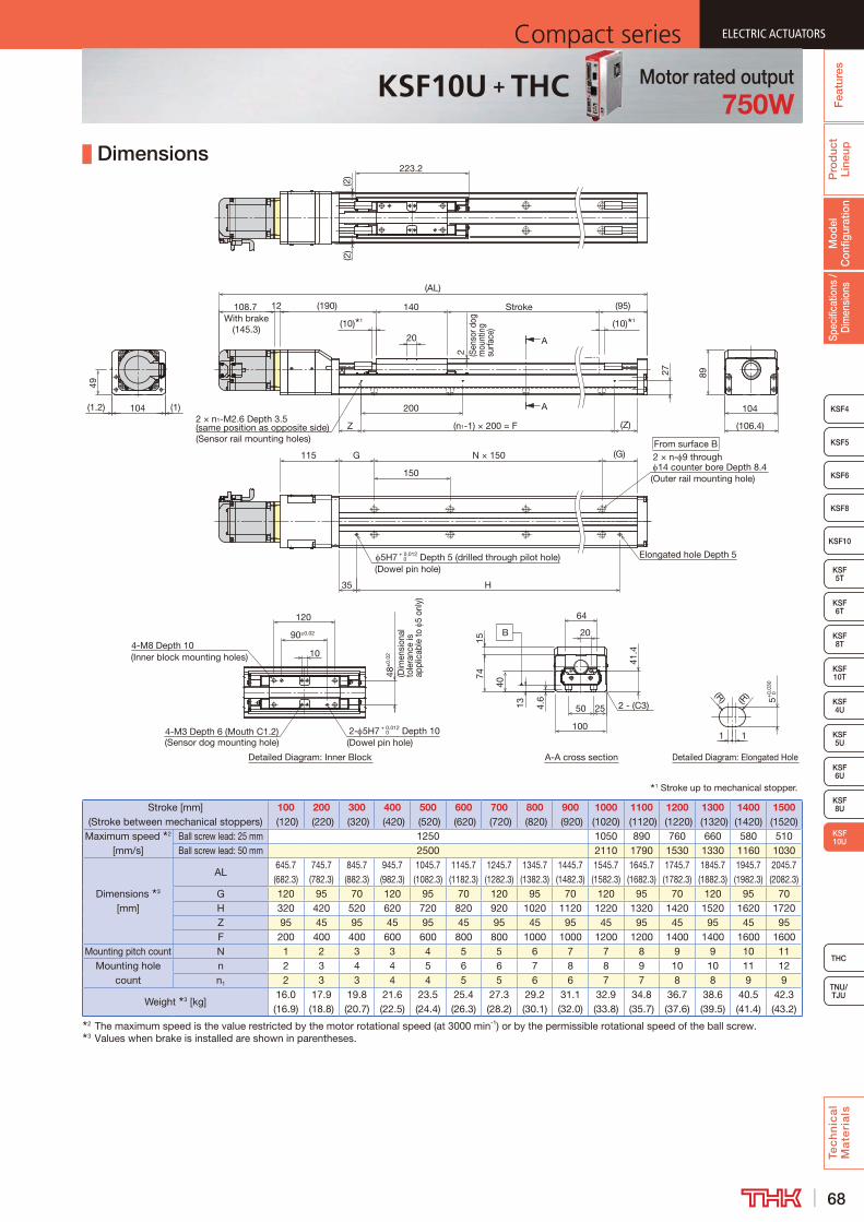
68
ELECTRIC ACTUATORSCompact series
Pro
duc
t Li
neup
Tec
hn
ica
l M
ate
ria
ls
THC
TNU/TJU
KSF8
KSF4
KSF 10T
KSF10
KSF 5T
KSF 6T
KSF 8T
KSF 4U
KSF 5U
KSF 6U
KSF 8U
Spec
ifica
tions
/ D
imen
sion
sM
odel
C
onfig
urat
ion
Fea
ture
s
ELECTRIC ACTUATORSCompact series
KSF5
KSF6
ELECTRIC ACTUATORSCompact series
KSF 10U
ELECTRIC ACTUATORSCompact series
KSF10U + THC Motor rated output750W
Dimensions
Stroke [mm] (Stroke between mechanical stoppers)
100 (120)
200 (220)
300 (320)
400 (420)
500 (520)
600 (620)
700 (720)
800 (820)
900 (920)
1000 (1020)
1100 (1120)
1200 (1220)
1300 (1320)
1400 (1420)
1500 (1520)
Maximum speed 2 [mm/s]
Ball screw lead: 25 mm 1250 1050 890 760 660 580 510Ball screw lead: 50 mm 2500 2110 1790 1530 1330 1160 1030
Dimensions 3 [mm]
AL645.7 (682.3)
745.7 (782.3)
845.7 (882.3)
945.7 (982.3)
1045.7 (1082.3)
1145.7 (1182.3)
1245.7 (1282.3)
1345.7 (1382.3)
1445.7 (1482.3)
1545.7 (1582.3)
1645.7 (1682.3)
1745.7 (1782.3)
1845.7 (1882.3)
1945.7 (1982.3)
2045.7 (2082.3)
G 120 95 70 120 95 70 120 95 70 120 95 70 120 95 70H 320 420 520 620 720 820 920 1020 1120 1220 1320 1420 1520 1620 1720Z 95 45 95 45 95 45 95 45 95 45 95 45 95 45 95F 200 400 400 600 600 800 800 1000 1000 1200 1200 1400 1400 1600 1600
Mounting pitch count N 1 2 3 3 4 5 5 6 7 7 8 9 9 10 11Mounting hole
countn 2 3 4 4 5 6 6 7 8 8 9 10 10 11 12n1 2 3 3 4 4 5 5 6 6 7 7 8 8 9 9
Weight 3 [kg]16.0 (16.9)
17.9 (18.8)
19.8 (20.7)
21.6 (22.5)
23.5 (24.4)
25.4 (26.3)
27.3 (28.2)
29.2 (30.1)
31.1 (32.0)
32.9 (33.8)
34.8 (35.7)
36.7 (37.6)
38.6 (39.5)
40.5 (41.4)
42.3 (43.2)
2 The maximum speed is the value restricted by the motor rotational speed (at 3000 min-1) or by the permissible rotational speed of the ball screw.3 Values when brake is installed are shown in parentheses.
1 Stroke up to mechanical stopper.
Detailed Diagram: Elongated Hole
A
A
Detailed Diagram: Inner Block A-A cross section
B
2 (Sen
sor d
og
mou
ntin
g su
rface
)
10
Stroke
2- 5H7 + 0.012 Depth 10 0
(Dowel pin hole)
140
(10) 1
(95)(190)
20
N × 150
(R) (R) 5+
0.03
0 0
11
From surface B2 × n- 9 through 14 counter bore Depth 8.4
(Outer rail mounting hole)
104
5H7 + 0.012 Depth 5 (drilled through pilot hole) 0
(Dowel pin hole)
Elongated hole Depth 5
H
(G)115 G
150
35
4-M8 Depth 10(Inner block mounting holes)
90±0.02
120
48±
0.02
(Dim
ensi
onal
to
lera
nce
is
appl
icab
le to
5
only
)
4-M3 Depth 6 (Mouth C1.2)(Sensor dog mounting hole)
223.2
(2)
(2)
200
12108.7With brake
(145.3)
(AL)
2 × n1-M2.6 Depth 3.5 (same position as opposite side)
(Sensor rail mounting holes)Z (n1-1) × 200 = F (106.4)
27 89
(Z)
104 (1)
49
(1.2)
64
2 - (C3)50
100
7415
25
2041
.4
40
4.6
13
(10) 1
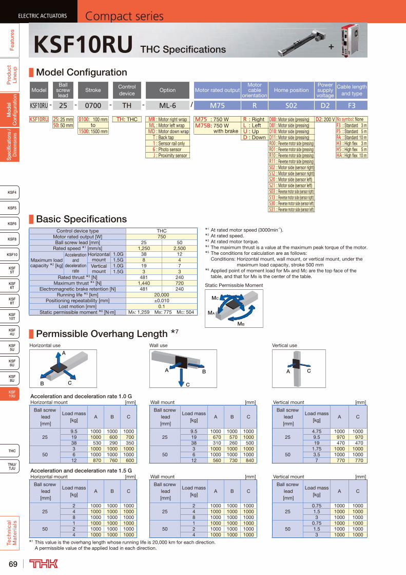
69
ELECTRIC ACTUATORS Compact seriesP
rod
uct
Line
upTe
ch
nic
al
Ma
teri
als
KSF8
KSF4
KSF 10T
KSF10
KSF 5T
KSF 6T
KSF 8T
KSF 4U
KSF 5U
KSF 6U
KSF 8U
TNU/TJU
THC
Spec
ifica
tions
/ D
imen
sion
sM
odel
C
onfig
urat
ion
Fea
ture
sELECTRIC ACTUATORS Compact series
KSF5
KSF6
ELECTRIC ACTUATORS Compact series
KSF 10U
ELECTRIC ACTUATORS Compact series
KSF10RU THC Specifications
Model Configuration
ModelBall
screw lead
StrokeControl device
Option Motor rated outputMotor cable
orientationHome position
Power supply voltage
Cable length and type
KSF10RU - 25 - 0700 - TH - ML-6 / M75 R S02 D2 F3
KSF10RU 25: 25 mm 0100: 100 mm TH: THC MR : Motor right wrap M75 : 750 W R : Right D00 : Motor side (pressing) D2: 200 V No symbol: None50: 50 mm to ML : Motor left wrap M75B: 750 W
with brakeL : Left D01 : Motor side (pressing) F3 : Standard 3 m
1500: 1500 mm MD : Motor down wrap U : Up D10 : Motor side (pressing) F5 : Standard 5 m T : Back tap D : Down D11 : Motor side (pressing) FA : Standard 10 m 1 : Sensor rail only R00 : Reverse motor side (pressing) H3 : High flex 3 m 6 : Photo sensor R01 : Reverse motor side (pressing) H5 : High flex 5 m J : Proximity sensor R10 : Reverse motor side (pressing) HA : High flex 10 m
R11 : Reverse motor side (pressing)S02 : Motor side (sensor right)S12 : Motor side (sensor right)S20 : Motor side (sensor left)S21 : Motor side (sensor left)S03 : Reverse motor side (sensor right)S13 : Reverse motor side (sensor right)S30 : Reverse motor side (sensor left)S31 : Reverse motor side (sensor left)
Basic SpecificationsControl device type THC
Motor rated output [W] 750Ball screw lead [mm] 25 50
Rated speed 1 [mm/s] 1,250 2,500
Maximum load capacity 2 [kg]
Acceleration and
deceleration rate
Horizontal mount
1.0G 38 121.5G 8 4
Vertical mount
1.0G 19 71.5G 3 3
Rated thrust 3 [N] 481 240Maximum thrust 4 [N] 1,440 720
Electromagnetic brake retention [N] 481 240Running life 5 [km] 20,000
Positioning repeatability [mm] ±0.010Lost motion [mm] 0.1
Static permissible moment 6 [N·m] MA: 1,259 MB: 775 MC: 504
Permissible Overhang Length 7
Horizontal use Wall use Vertical use
CB
A
A B
C
A C
Acceleration and deceleration rate 1.0 GHorizontal mount [mm] Wall mount [mm] Vertical mount [mm]
Ball screw lead [mm]
Load mass [kg]
A B CBall screw
lead [mm]
Load mass [kg]
A B CBall screw
lead [mm]
Load mass [kg]
A C
259.5 1000 1000 1000
259.5 1000 1000 1000
254.75 1000 1000
19 1000 600 700 19 670 570 1000 9.5 970 97038 530 290 350 38 310 260 500 19 470 470
503 1000 1000 1000
503 1000 1000 1000
501.75 1000 1000
6 1000 1000 1000 6 1000 1000 1000 3.5 1000 100012 870 760 600 12 560 730 840 7 770 770
Acceleration and deceleration rate 1.5 GHorizontal mount [mm] Wall mount [mm] Vertical mount [mm]
Ball screw lead [mm]
Load mass [kg]
A B CBall screw
lead [mm]
Load mass [kg]
A B CBall screw
lead [mm]
Load mass [kg]
A C
252 1000 1000 1000
252 1000 1000 1000
250.75 1000 1000
4 1000 1000 1000 4 1000 1000 1000 1.5 1000 10008 1000 1000 1000 8 1000 1000 1000 3 1000 1000
501 1000 1000 1000
501 1000 1000 1000
500.75 1000 1000
2 1000 1000 1000 2 1000 1000 1000 1.5 1000 10004 1000 1000 1000 4 1000 1000 1000 3 1000 1000
7 This value is the overhang length whose running life is 20,000 km for each direction. A permissible value of the applied load in each direction.
MB
MA
MC
Static Permissible Moment
1 At rated motor speed (3000min-1).2 At rated speed.3 At rated motor torque.4 The maximum thrust is a value at the maximum peak torque of the motor.5 The conditions for calculation are as follows:
Conditions: Horizontal mount, wall mount, or vertical mount, under the maximum load capacity, stroke 500 mm
6 Applied point of moment load for MA and MC are the top face of the table, and that for MB is the center of the table.
+
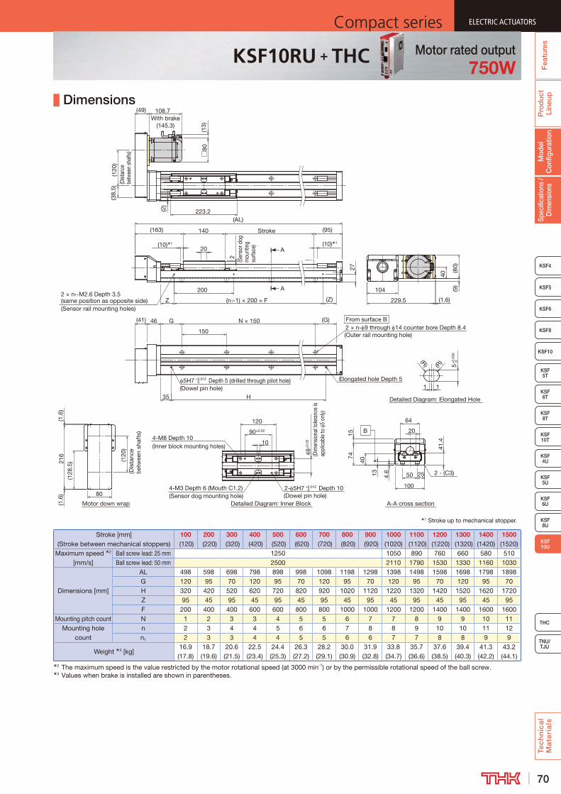
70
ELECTRIC ACTUATORSCompact series
Pro
duc
t Li
neup
Tec
hn
ica
l M
ate
ria
ls
THC
TNU/TJU
KSF8
KSF4
KSF 10T
KSF10
KSF 5T
KSF 6T
KSF 8T
KSF 4U
KSF 5U
KSF 6U
KSF 8U
Spec
ifica
tions
/ D
imen
sion
sM
odel
C
onfig
urat
ion
Fea
ture
s
ELECTRIC ACTUATORSCompact series
KSF5
KSF6
ELECTRIC ACTUATORSCompact series
KSF 10U
ELECTRIC ACTUATORSCompact series
KSF10RU + THC Motor rated output750W
Dimensions
Stroke [mm] (Stroke between mechanical stoppers)
100 (120)
200 (220)
300 (320)
400 (420)
500 (520)
600 (620)
700 (720)
800 (820)
900 (920)
1000 (1020)
1100 (1120)
1200 (1220)
1300 (1320)
1400 (1420)
1500 (1520)
Maximum speed 2 [mm/s]
Ball screw lead: 25 mm 1250 1050 890 760 660 580 510Ball screw lead: 50 mm 2500 2110 1790 1530 1330 1160 1030
Dimensions [mm]
AL 498 598 698 798 898 998 1098 1198 1298 1398 1498 1598 1698 1798 1898G 120 95 70 120 95 70 120 95 70 120 95 70 120 95 70H 320 420 520 620 720 820 920 1020 1120 1220 1320 1420 1520 1620 1720Z 95 45 95 45 95 45 95 45 95 45 95 45 95 45 95F 200 400 400 600 600 800 800 1000 1000 1200 1200 1400 1400 1600 1600
Mounting pitch count N 1 2 3 3 4 5 5 6 7 7 8 9 9 10 11Mounting hole
countn 2 3 4 4 5 6 6 7 8 8 9 10 10 11 12n1 2 3 3 4 4 5 5 6 6 7 7 8 8 9 9
Weight 3 [kg]16.9 (17.8)
18.7 (19.6)
20.6 (21.5)
22.5 (23.4)
24.4 (25.3)
26.3 (27.2)
28.2 (29.1)
30.0 (30.9)
31.9 (32.8)
33.8 (34.7)
35.7 (36.6)
37.6 (38.5)
39.4 (40.3)
41.3 (42.2)
43.2 (44.1)
2 The maximum speed is the value restricted by the motor rotational speed (at 3000 min-1) or by the permissible rotational speed of the ball screw.3 Values when brake is installed are shown in parentheses.
Motor down wrap
1 Stroke up to mechanical stopper.
Detailed Diagram: Elongated Hole
Detailed Diagram: Inner Block
A
A
A-A cross section
B
4-M3 Depth 6 (Mouth C1.2)(Sensor dog mounting hole)
48±
0.02
(Dim
ensio
nal t
oler
ance
is
appl
icab
le to
5
only)
120
90±0.02
4-M8 Depth 10(Inner block mounting holes)
1 1
5+
0.03
0 0
(R)(R)
2- 5H7 +0.012 0 Depth 10
(Dowel pin hole)
10
(120
)(D
ista
nce
bet
wee
n sh
afts
)
(128
.5)21
6(1
.6)
(1.6
)
80
27
2(S
enso
r dog
m
ount
ing
surfa
ce)
Stroke140
(10) 1
(95)
20
From surface B2 × n- 9 through 14 counter bore Depth 8.4(Outer rail mounting hole)
46
150
5H7 +0.012 0 Depth 5 (drilled through pilot hole) Elongated hole Depth 5
H
G (G)N × 150
35
(10) 1
(41)
200
(n1-1) × 200 = FZ (Z)2 × n1-M2.6 Depth 3.5 (same position as opposite side)(Sensor rail mounting holes)
(163)
(AL)
(2)
(49)(3
8.5)
(120
)(D
istan
ce
betw
een
shaf
ts)
223.2□
80(1
3)
108.7With brake
(145.3)
104
229.5 (1.6)
40
(9)
(80)
64
2 - (C3)50
100
7415
25
20
41.4
40
4.613
(Dowel pin hole)
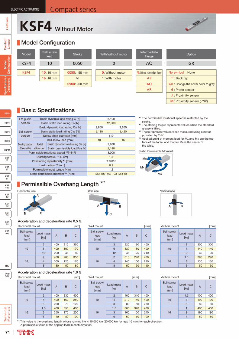
71
ELECTRIC ACTUATORS Compact seriesF
eatu
res
Pro
duc
t Li
neup
Tec
hn
ica
l M
ate
ria
ls
KSF8
KSF5
KSF6
KSF 10T
KSF10
KSF 5T
KSF 6T
KSF 8T
KSF 10U
KSF 4U
KSF 5U
KSF 6U
KSF 8U
TNU/TJU
THC
Fea
ture
s
KSF4
Spec
ifica
tions
/ D
imen
sion
sM
odel
C
onfig
urat
ion
Pro
duc
t Li
neup
KSF4 Without Motor
Model Configuration
ModelBall screw
leadStroke With/without motor
Intermediate flange
Option
KSF4 - 10 - 0050 - 0 - AQ - GR
KSF4 10: 10 mm 0050: 50 mm 0: Without motor A0: Without intermediate flange No symbol : None
16: 16 mm to 1: With motor AP T : Back tap
0900: 900 mm AQ GR : Change the cover color to gray
AR 6 : Photo sensor
J : Proximity sensor
M : Proximity sensor (PNP)
Basic SpecificationsLM guide portion
Basic dynamic load rating C [N] 6,400
Basic static load rating C0 [N] 12,900
Ball screw portion
Basic dynamic load rating Ca [N] 2,860 1,850
Basic static load rating C0a [N] 5,110 3,420
Screw shaft diameter [mm] 10
Ball screw lead [mm] 10 16
Bearing portion (Fixed side)
Axial direction
Basic dynamic load rating Ca [N] 2,930
Static permissible load P0a [N] 2,140
Permissible rotational speed 1[min-1] 3,000
Starting torque 2 [N·cm] 1.5
Positioning repeatability 3 [mm] ±0.010
Lost motion 3 [mm] 0.1
Permissible input torque [N·m] 1.2
Static permissible moment 4 [N·m] MA: 103 MB: 103 MC: 58
Permissible Overhang Length 7
Horizontal use Wall use Vertical use
CB
A
A B
C
A C
Acceleration and deceleration rate 0.5 GHorizontal mount [mm] Wall mount [mm] Vertical mount [mm]
Ball screw lead [mm]
Load mass [kg]
A B CBall screw
lead [mm]
Load mass [kg]
A B CBall screw
lead [mm]
Load mass [kg]
A C
10
3 400 210 350
10
3 320 190 400
10
2 300 300
6 400 100 170 6 130 80 400 4 140 140
12 260 45 80 12 45 25 210 8 60 60
16
2 400 260 350
16
2 310 240 400
16
1.5 290 290
4 300 120 170 4 140 100 280 3 130 130
8 130 50 80 8 50 30 110 6 50 50
Acceleration and deceleration rate 1.0 GHorizontal mount [mm] Wall mount [mm] Vertical mount [mm]
Ball screw lead [mm]
Load mass [kg]
A B CBall screw
lead [mm]
Load mass [kg]
A B CBall screw
lead [mm]
Load mass [kg]
A C
10
2 400 330 400
10
2 400 310 400
10
1.5 400 400
4 400 160 250 4 210 140 400 3 190 190
8 250 70 120 8 80 50 230 6 80 80
16
1.5 400 350 400
16
1.5 360 320 400
16
1 400 400
3 250 170 200 3 160 150 240 2 190 190
6 110 80 100 6 60 60 100 4 80 807 This value is the overhang length whose running life is 10,000 km (20,000 km for lead 16 mm) for each direction.
A permissible value of the applied load in each direction.
1 The permissible rotational speed is restricted by the stroke.
2 The starting torque represents values when the standard grease is filled.
3 These represent values when measured using a motor provided by THK.
4 Applied point of moment load for MA and MC are the top face of the table, and that for MB is the center of the table.
MB
MA
MC
Static Permissible Moment

72
ELECTRIC ACTUATORSCompact series
Fea
ture
sP
rod
uct
Line
upTe
ch
nic
al
Ma
teri
als
THC
TNU/TJU
KSF8
KSF5
KSF6
KSF 10T
KSF10
KSF 5T
KSF 6T
KSF 8T
KSF 10U
KSF 4U
KSF 5U
KSF 6U
KSF 8U
Fea
ture
sSp
ecifi
catio
ns /
Dim
ensi
ons
KSF4
Mod
el
Con
figur
atio
nP
rod
uct
Line
up Dimensions
1 Stroke up to mechanical stopper.2 The T slot in Section A is provided exclusively for sensor mounting. Do not use it for any other purpose.3 See P.135 for intermediate flange dimensions.
Detailed drawing of motor mounting part (when A0 is selected) 3
Detailed Diagram: Outer Rail Mounting HoleDetailed Diagram: Table
Detailed Diagram: Section A 2
B
(G) 69
A 2
27
18
46
43
4-M4 Depth 6.5
(Table mounting hole)
34±0.02
20
50
(AL)
34
N × 120
43
60
120
G
(63)Stroke
(10) 1
(115)
(10) 1
27±
0.02
(Dim
ensi
onal
tole
ranc
e is
ap
plic
able
to
3 on
ly)
30°
2-M3 Depth 6(Intermediate flange mounting hole)
2- 3.4 through(Intermediate flange mounting hole)
7.7
4-M2.6 Depth 4.5 (Mouth C1)
(Sensor dog mounting hole)
2 - 3H7 + 0.010 0 Depth 5
(Dowel pin hole)
52
6.5
3.4
(120)
(1.2
)0.
35
(43)
(Tab
le
cove
r wid
th)
(23.
2)
PCD40
21
(33.
2)
2.4
5 (
Sens
or d
og
m
ount
ing
su
rface
)
(Dowel pin hole)H1 H2 (R
)
1 1
4+0.
030
0
(R)
Elongated hole Depth 4
From surface B
2 × n- 3.4 through 6.5 counter bore Depth 3
(Outer rail mounting hole)
4H7 + 0.012 0 Depth 4 (drilled through pilot hole)
Detailed Diagram: Elongated Hole
(45.4)
60
0.8
5.7
3.5
2.4
1.3
6H7 -
0.01
2 0
30H
7 0+0.
021 7
3
28
25 13
23.8
5
Stroke [mm] (Stroke between mechanical stoppers)
50 (70)
100 (120)
150 (170)
200 (220)
250 (270)
300 (320)
350 (370)
400 (420)
450 (470)
Maximum speed 4 5 [mm/s]
Ball screw lead: 10 mm 500Ball screw lead: 16 mm 800
Dimensions [mm]
AL 288 338 388 438 488 538 588 638 688G 41 66 91 56 81 46 71 96 61H1 48 48 48 63 63 63 48 48 48H2 75 125 175 225 275 325 375 425 475
Mounting pitch count N 1 1 1 2 2 3 3 3 4Mounting hole count n 2 2 2 3 3 4 4 4 5
Weight [kg] 1.5 1.7 1.9 2.1 2.3 2.5 2.7 2.9 3.0Stroke (mm)
(Stroke between mechanical stoppers)500 (520)
550 (570)
600 (620)
650 (670)
700 (720)
750 (770)
800 (820)
850 (870)
900 (920)
Maximum speed 4 5 [mm/s]
Ball screw lead: 10 mm 500 430 370 320 290 250 230 200Ball screw lead: 16 mm 800 690 600 520 460 410 360 330
Dimensions [mm]
AL 738 788 838 888 938 988 1038 1088 1138G 86 51 76 41 66 91 56 81 46H1 63 63 63 48 48 48 63 63 63H2 525 575 625 675 725 775 825 875 925
Mounting pitch count N 4 5 5 6 6 6 7 7 8Mounting hole count n 5 6 6 7 7 7 8 8 9
Weight [kg] 3.2 3.4 3.6 3.8 4.0 4.2 4.4 4.6 4.74 The maximum speed varies depending on the motor you use.5 The maximum speed is the value restricted by the permissible rotational speed of the ball screw.
KSF4
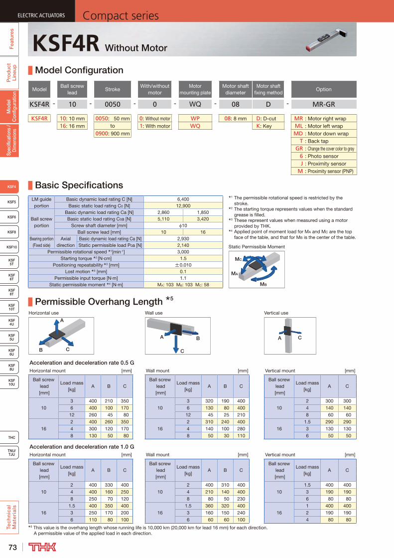
73
ELECTRIC ACTUATORS Compact seriesF
eatu
res
Pro
duc
t Li
neup
Tec
hn
ica
l M
ate
ria
ls
KSF8
KSF5
KSF6
KSF 10T
KSF10
KSF 5T
KSF 6T
KSF 8T
KSF 10U
KSF 4U
KSF 5U
KSF 6U
KSF 8U
TNU/TJU
THC
Fea
ture
s
KSF4
Spec
ifica
tions
/ D
imen
sion
sM
odel
C
onfig
urat
ion
Pro
duc
t Li
neup
KSF4R Without Motor
Model Configuration
ModelBall screw
leadStroke
With/without motor
Motor mounting plate
Motor shaft diameter
Motor shaft fixing method
Option
KSF4R - 10 - 0050 - 0 - WQ - 08 D - MR-GR
KSF4R 10: 10 mm 0050: 50 mm 0: Without motor WP 08: 8 mm D : D-cut MR : Motor right wrap16: 16 mm to 1: With motor WQ K : Key ML : Motor left wrap
0900: 900 mm MD : Motor down wrap T : Back tap GR : Change the cover color to gray 6 : Photo sensor J : Proximity sensor M : Proximity sensor (PNP)
Basic SpecificationsLM guide portion
Basic dynamic load rating C [N] 6,400Basic static load rating C0 [N] 12,900
Ball screw portion
Basic dynamic load rating Ca [N] 2,860 1,850Basic static load rating C0a [N] 5,110 3,420
Screw shaft diameter [mm] 10Ball screw lead [mm] 10 16
Bearing portion (Fixed side)
Axial direction
Basic dynamic load rating Ca [N] 2,930Static permissible load P0a [N] 2,140
Permissible rotational speed 1[min-1] 3,000Starting torque 2 [N·cm] 1.5
Positioning repeatability 3 [mm] ±0.010Lost motion 3 [mm] 0.1
Permissible input torque [N·m] 1.1Static permissible moment 4 [N·m] MA: 103 MB: 103 MC: 58
Permissible Overhang Length 5
Horizontal use Wall use Vertical use
CB
A
A B
C
A C
Acceleration and deceleration rate 0.5 GHorizontal mount [mm] Wall mount [mm] Vertical mount [mm]
Ball screw lead [mm]
Load mass [kg]
A B CBall screw
lead [mm]
Load mass [kg]
A B CBall screw
lead [mm]
Load mass [kg]
A C
10
3 400 210 350
10
3 320 190 400
10
2 300 300
6 400 100 170 6 130 80 400 4 140 140
12 260 45 80 12 45 25 210 8 60 60
16
2 400 260 350
16
2 310 240 400
16
1.5 290 290
4 300 120 170 4 140 100 280 3 130 130
8 130 50 80 8 50 30 110 6 50 50
Acceleration and deceleration rate 1.0 GHorizontal mount [mm] Wall mount [mm] Vertical mount [mm]
Ball screw lead [mm]
Load mass [kg]
A B CBall screw
lead [mm]
Load mass [kg]
A B CBall screw
lead [mm]
Load mass [kg]
A C
10
2 400 330 400
10
2 400 310 400
10
1.5 400 400
4 400 160 250 4 210 140 400 3 190 190
8 250 70 120 8 80 50 230 6 80 80
16
1.5 400 350 400
16
1.5 360 320 400
16
1 400 400
3 250 170 200 3 160 150 240 2 190 190
6 110 80 100 6 60 60 100 4 80 805 This value is the overhang length whose running life is 10,000 km (20,000 km for lead 16 mm) for each direction.
A permissible value of the applied load in each direction.
1 The permissible rotational speed is restricted by the stroke.
2 The starting torque represents values when the standard grease is filled.
3 These represent values when measured using a motor provided by THK.
4 Applied point of moment load for MA and MC are the top face of the table, and that for MB is the center of the table.
MB
MA
MC
Static Permissible Moment
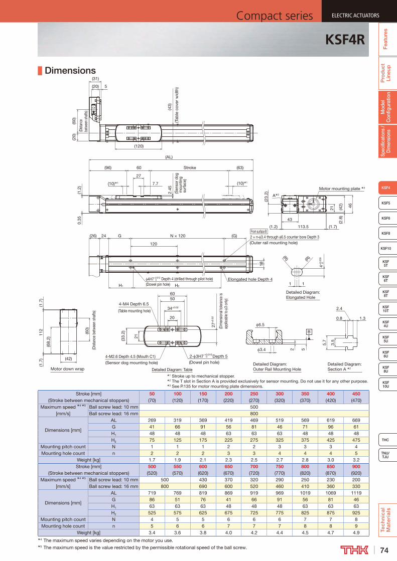
74
ELECTRIC ACTUATORSCompact series
Fea
ture
sP
rod
uct
Line
upTe
ch
nic
al
Ma
teri
als
THC
TNU/TJU
KSF8
KSF5
KSF6
KSF 10T
KSF10
KSF 5T
KSF 6T
KSF 8T
KSF 10U
KSF 4U
KSF 5U
KSF 6U
KSF 8U
Fea
ture
sSp
ecifi
catio
ns /
Dim
ensi
ons
KSF4
Mod
el
Con
figur
atio
nP
rod
uct
Line
up Dimensions
Stroke [mm] (Stroke between mechanical stoppers)
50 (70)
100 (120)
150 (170)
200 (220)
250 (270)
300 (320)
350 (370)
400 (420)
450 (470)
Maximum speed 4 5 [mm/s]
Ball screw lead: 10 mm 500Ball screw lead: 16 mm 800
Dimensions [mm]
AL 269 319 369 419 469 519 569 619 669G 41 66 91 56 81 46 71 96 61H1 48 48 48 63 63 63 48 48 48H2 75 125 175 225 275 325 375 425 475
Mounting pitch count N 1 1 1 2 2 3 3 3 4Mounting hole count n 2 2 2 3 3 4 4 4 5
Weight [kg] 1.7 1.9 2.1 2.3 2.5 2.7 2.8 3.0 3.2Stroke [mm]
(Stroke between mechanical stoppers)500 (520)
550 (570)
600 (620)
650 (670)
700 (720)
750 (770)
800 (820)
850 (870)
900 (920)
Maximum speed 4 5 [mm/s]
Ball screw lead: 10 mm 500 430 370 320 290 250 230 200Ball screw lead: 16 mm 800 690 600 520 460 410 360 330
Dimensions [mm]
AL 719 769 819 869 919 969 1019 1069 1119G 86 51 76 41 66 91 56 81 46H1 63 63 63 48 48 48 63 63 63H2 525 575 625 675 725 775 825 875 925
Mounting pitch count N 4 5 5 6 6 6 7 7 8Mounting hole count n 5 6 6 7 7 7 8 8 9
Weight [kg] 3.4 3.6 3.8 4.0 4.2 4.4 4.5 4.7 4.94 The maximum speed varies depending on the motor you use.5 The maximum speed is the value restricted by the permissible rotational speed of the ball screw.
KSF4R
1 Stroke up to mechanical stopper.2 The T slot in Section A is provided exclusively for sensor mounting. Do not use it for any other purpose.3 See P.135 for motor mounting plate dimensions.
(43)
(Tab
le c
over
wid
th)
(60)
(Dist
ance
be
twee
n sh
afts)
(10) 1
27
(10) 1 7.7
Stroke2.
45
(AL)
(96)
(20)
(120)
5(20)
(31)0.
35(1
.2)
(63)60
(Sen
sor d
og m
ount
ing
sur
face
)
43
113.5
46
(1.2)
A 2
Motor mounting plate 3
(23.
2)
21 (42)
(1.7)
(2.8
)
Detailed Diagram: Outer Rail Mounting HoleDetailed Diagram: Table
Detailed Diagram: Section A 2
B
4-M4 Depth 6.5
(Table mounting hole)34±0.02
20
50
27±
0.02
(Dim
ensio
nal t
oler
ance
is
appl
icabl
e to
3
only)
4-M2.6 Depth 4.5 (Mouth C1)(Sensor dog mounting hole)
2- 3H7 +0.010 0 Depth 5(Dowel pin hole)
52
6.5
3.4
21
(33.
2)
60
0.85.
7
3.5
2.4
1.3
From surface B2 × n- 3.4 through 6.5 counter bore Depth 3(Outer rail mounting hole)
Elongated hole Depth 44H7+0.0120 Depth 4 (drilled through pilot hole)
(G)
18
N × 12024(26)
Motor down wrap
H2H1
G
120
Detailed Diagram: Elongated Hole
(R)
1 1
4+0.
030
0
(R)
112
(60)
(Dist
ance
bet
wee
n sh
afts
)
(42)
(1.7
)
(68.
2)
(1.7
)
(Dowel pin hole)
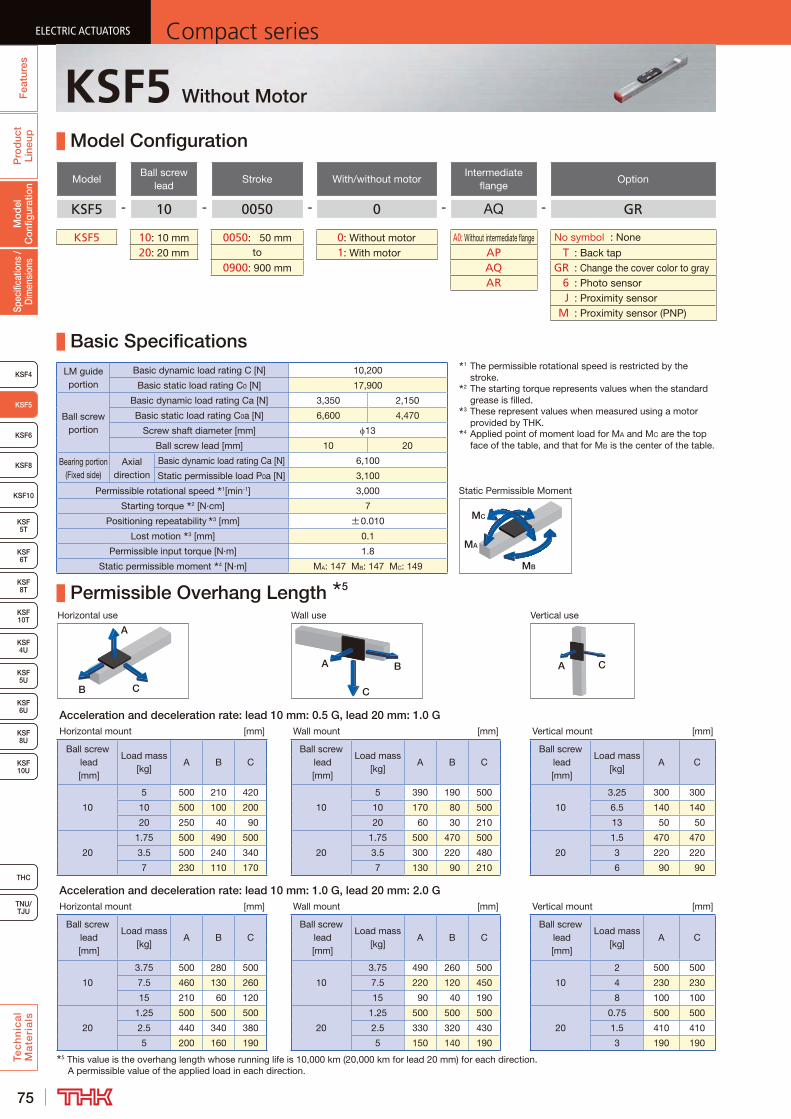
75
ELECTRIC ACTUATORS Compact seriesP
rod
uct
Line
upTe
ch
nic
al
Ma
teri
als
KSF8
KSF4
KSF 10T
KSF10
KSF 5T
KSF 6T
KSF 8T
KSF 10U
KSF 4U
KSF 5U
KSF 6U
KSF 8U
TNU/TJU
THC
KSF5
KSF6
Spec
ifica
tions
/ D
imen
sion
sM
odel
C
onfig
urat
ion
Fea
ture
sELECTRIC ACTUATORS Compact series
KSF5 Without Motor
Model Configuration
ModelBall screw
leadStroke With/without motor
Intermediate flange
Option
KSF5 - 10 - 0050 - 0 - AQ - GR
KSF5 10: 10 mm 0050: 50 mm 0: Without motor A0: Without intermediate flange No symbol : None
20: 20 mm to 1: With motor AP T : Back tap0900: 900 mm AQ GR : Change the cover color to gray
AR 6 : Photo sensor J : Proximity sensor M : Proximity sensor (PNP)
Basic SpecificationsLM guide portion
Basic dynamic load rating C [N] 10,200
Basic static load rating C0 [N] 17,900
Ball screw portion
Basic dynamic load rating Ca [N] 3,350 2,150
Basic static load rating C0a [N] 6,600 4,470
Screw shaft diameter [mm] 13
Ball screw lead [mm] 10 20
Bearing portion (Fixed side)
Axial direction
Basic dynamic load rating Ca [N] 6,100
Static permissible load P0a [N] 3,100
Permissible rotational speed 1[min-1] 3,000
Starting torque 2 [N·cm] 7
Positioning repeatability 3 [mm] ±0.010
Lost motion 3 [mm] 0.1
Permissible input torque [N·m] 1.8
Static permissible moment 4 [N·m] MA: 147 MB: 147 MC: 149
Permissible Overhang Length 5
Horizontal use Wall use Vertical use
CB
A
A B
C
A C
Acceleration and deceleration rate: lead 10 mm: 0.5 G, lead 20 mm: 1.0 GHorizontal mount [mm] Wall mount [mm] Vertical mount [mm]
Ball screw lead [mm]
Load mass [kg]
A B CBall screw
lead [mm]
Load mass [kg]
A B CBall screw
lead [mm]
Load mass [kg]
A C
10
5 500 210 420
10
5 390 190 500
10
3.25 300 300
10 500 100 200 10 170 80 500 6.5 140 140
20 250 40 90 20 60 30 210 13 50 50
20
1.75 500 490 500
20
1.75 500 470 500
20
1.5 470 470
3.5 500 240 340 3.5 300 220 480 3 220 220
7 230 110 170 7 130 90 210 6 90 90
Acceleration and deceleration rate: lead 10 mm: 1.0 G, lead 20 mm: 2.0 GHorizontal mount [mm] Wall mount [mm] Vertical mount [mm]
Ball screw lead [mm]
Load mass [kg]
A B CBall screw
lead [mm]
Load mass [kg]
A B CBall screw
lead [mm]
Load mass [kg]
A C
10
3.75 500 280 500
10
3.75 490 260 500
10
2 500 500
7.5 460 130 260 7.5 220 120 450 4 230 230
15 210 60 120 15 90 40 190 8 100 100
20
1.25 500 500 500
20
1.25 500 500 500
20
0.75 500 500
2.5 440 340 380 2.5 330 320 430 1.5 410 410
5 200 160 190 5 150 140 190 3 190 1905 This value is the overhang length whose running life is 10,000 km (20,000 km for lead 20 mm) for each direction.
A permissible value of the applied load in each direction.
1 The permissible rotational speed is restricted by the stroke.
2 The starting torque represents values when the standard grease is filled.
3 These represent values when measured using a motor provided by THK.
4 Applied point of moment load for MA and MC are the top face of the table, and that for MB is the center of the table.
MB
MA
MC
Static Permissible Moment

76
ELECTRIC ACTUATORSCompact series
Pro
duc
t Li
neup
Tec
hn
ica
l M
ate
ria
ls
THC
TNU/TJU
KSF8
KSF4
KSF 10T
KSF10
KSF 5T
KSF 6T
KSF 8T
KSF 10U
KSF 4U
KSF 5U
KSF 6U
KSF 8U
KSF5
KSF6
Spec
ifica
tions
/ D
imen
sion
sM
odel
C
onfig
urat
ion
Fea
ture
s
ELECTRIC ACTUATORSCompact series
Dimensions
1 Stroke up to mechanical stopper.2 The T slot in Section A is provided exclusively for sensor mounting.
Do not use it for any other purpose.3 See P.136 for intermediate flange dimensions.
Detailed drawing of motor mounting part (when A0 is selected) 3
From surface B
13
28
3
7
25
24
8h7
0 -0.0
15
30H
7+
0.02
1 0 10
(120)
(70)
(30)
2-M3 Depth 6(Intermediate flange mounting hole)
2- 3.4 through(Intermediate flange mounting hole)
34
30°
52.6
50
(55)
2 × n- 4.5 through 8 counter bore Depth 4(Outer rail mounting hole)
25
(10) 1 (10) 1
2.3
(Sen
sor d
og
mou
ntin
g s
urfa
ce)
Elongated hole Depth 4
4H7 +0.012 0 Depth 4 (drilled through pilot hole)
G75(5
0)
(Tab
le c
over
wid
th)
H37
7.7
27
60(127) Stroke
120
N × 120 (G)
PCD40
A 2
7
(5)
0.5
(AL)
Detailed Diagram: Outer Rail Mounting Hole
Detailed Diagram: Table
B
Detailed Diagram: Elongated Hole
Detailed Diagram: Section A 2
1.30.8
2.4
3.5
5.7
4
1
(R)
8
(R)
1
2
4.5(41) 6
2- 3H7 Depth 5
(Dowel pin hole)
20
27
34±
0.02
(Dim
ensio
nal t
oler
ance
is
appl
icab
le to
3
only)
4 - M2.6 Depth 5 (Mouth C1)
(Sensor dog mounting hole)
4-M4 Depth 8(Table mounting hole)
50
34±0.02
60
0+0.010
0+0.
030
(Dowel pin hole)
Stroke [mm] (Stroke between mechanical stoppers)
50 (70)
100 (120)
150 (170)
200 (220)
250 (270)
300 (320)
350 (370)
400 (420)
450 (470)
Maximum speed 4 5 [mm/s]
Ball screw lead: 10 mm 500Ball screw lead: 20 mm 1000
Dimensions [mm]AL 307 357 407 457 507 557 607 657 707G 47 72 97 62 87 52 77 102 67H 140 190 240 290 340 390 440 490 540
Mounting pitch count N 1 1 1 2 2 3 3 3 4Mounting hole count n 2 2 2 3 3 4 4 4 5
Weight [kg] 2.3 2.6 2.8 3.1 3.4 3.7 4.0 4.2 4.5Stroke [mm]
(Stroke between mechanical stoppers)500 (520)
550 (570)
600 (620)
650 (670)
700 (720)
750 (770)
800 (820)
850 (870)
900 (920)
Maximum speed 4 5 [mm/s]
Ball screw lead: 10 mm 500 440 390 340 310 270 250Ball screw lead: 20 mm 1000 890 780 690 620 550 500
Dimensions [mm]AL 757 807 857 907 957 1007 1057 1107 1157G 92 57 82 47 72 97 62 87 52H 590 640 690 740 790 840 890 940 990
Mounting pitch count N 4 5 5 6 6 6 7 7 8Mounting hole count n 5 6 6 7 7 7 8 8 9
Weight [kg] 4.8 5.1 5.4 5.6 5.9 6.2 6.5 6.8 7.04 The maximum speed varies depending on the motor you use.5 The maximum speed is the value restricted by the permissible rotational speed of the ball screw.
KSF5

77
ELECTRIC ACTUATORS Compact seriesP
rod
uct
Line
upTe
ch
nic
al
Ma
teri
als
KSF8
KSF4
KSF 10T
KSF10
KSF 5T
KSF 6T
KSF 8T
KSF 10U
KSF 4U
KSF 5U
KSF 6U
KSF 8U
TNU/TJU
THC
KSF5
KSF6
Spec
ifica
tions
/ D
imen
sion
sM
odel
C
onfig
urat
ion
Fea
ture
sELECTRIC ACTUATORS Compact series
KSF5R Without Motor
Model Configuration
ModelBall screw
leadStroke
With/without motor
Motor mounting plate
Motor shaft diameter
Motor shaft fixing method
Option
KSF5R - 10 - 0050 - 0 - WQ - 08 D - MR-GR
KSF5R 10: 10 mm 0050: 50 mm 0: Without motor WP 08: 8 mm D : D-cut MR : Motor right wrap20: 20 mm to 1: With motor WQ K : Key ML : Motor left wrap
0900: 900 mm MD : Motor down wrap T : Back tap GR : Change the cover color to gray 6 : Photo sensor J : Proximity sensor M : Proximity sensor (PNP)
Basic SpecificationsLM guide portion
Basic dynamic load rating C [N] 10,200Basic static load rating C0 [N] 17,900
Ball screw portion
Basic dynamic load rating Ca [N] 3,350 2,150Basic static load rating C0a [N] 6,600 4,470
Screw shaft diameter [mm] 13Ball screw lead [mm] 10 20
Bearing portion (Fixed side)
Axial direction
Basic dynamic load rating Ca [N] 6,100Static permissible load P0a [N] 3,100
Permissible rotational speed 1[min-1] 3,000Starting torque 2 [N·cm] 7
Positioning repeatability 3 [mm] ±0.010Lost motion 3 [mm] 0.1
Permissible input torque [N·m] 1.1Static permissible moment 4 [N·m] MA: 147 MB: 147 MC: 149
Permissible Overhang Length 5
Horizontal use Wall use Vertical use
CB
A
A B
C
A C
Acceleration and deceleration rate: lead 10 mm: 0.5 G, lead 20 mm: 1.0 GHorizontal mount [mm] Wall mount [mm] Vertical mount [mm]
Ball screw lead [mm]
Load mass [kg]
A B CBall screw
lead [mm]
Load mass [kg]
A B CBall screw
lead [mm]
Load mass [kg]
A C
10
5 500 210 420
10
5 390 190 500
10
2.75 360 360
10 500 100 200 10 170 80 500 5.5 170 170
20 250 40 90 20 60 30 210 11 70 70
20
1.75 500 490 500
20
1.75 500 470 500
20
1.25 500 500
3.5 500 240 340 3.5 300 220 480 2.5 270 270
7 230 110 170 7 130 90 210 5 120 120
Acceleration and deceleration rate: lead 10 mm: 1.0 G, lead 20 mm: 2.0 GHorizontal mount [mm] Wall mount [mm] Vertical mount [mm]
Ball screw lead [mm]
Load mass [kg]
A B CBall screw
lead [mm]
Load mass [kg]
A B CBall screw
lead [mm]
Load mass [kg]
A C
10
3.75 500 280 500
10
3.75 490 260 500
10
2 500 500
7.5 460 130 260 7.5 220 120 450 4 230 230
15 210 60 120 15 90 40 190 8 100 100
20
1 500 500 500
20
1 500 500 500
20
0.63 500 500
2 500 420 480 2 430 410 500 1.25 500 500
4 260 210 240 4 190 190 250 2.5 240 2405 This value is the overhang length whose running life is 10,000 km (20,000 km for lead 20 mm) for each direction.
A permissible value of the applied load in each direction.
1 The permissible rotational speed is restricted by the stroke.
2 The starting torque represents values when the standard grease is filled.
3 These represent values when measured using a motor provided by THK.
4 Applied point of moment load for MA and MC are the top face of the table, and that for MB is the center of the table.
MB
MA
MC
Static Permissible Moment

78
ELECTRIC ACTUATORSCompact series
Pro
duc
t Li
neup
Tec
hn
ica
l M
ate
ria
ls
THC
TNU/TJU
KSF8
KSF4
KSF 10T
KSF10
KSF 5T
KSF 6T
KSF 8T
KSF 10U
KSF 4U
KSF 5U
KSF 6U
KSF 8U
KSF5
KSF6
Spec
ifica
tions
/ D
imen
sion
sM
odel
C
onfig
urat
ion
Fea
ture
s
ELECTRIC ACTUATORSCompact series
Dimensions
1 Stroke up to mechanical stopper.2 The T slot in Section A is provided exclusively for sensor mounting.
Do not use it for any other purpose.3 See P.136 for motor mounting plate dimensions.
(AL)
27
60
(60)
(Dist
ance
be
twee
n sh
afts)
(10) 1 (10) 1
Stroke
(120)
(5)
0.5
(70)(106)
(20)
(22) 5
(50)
(Tab
le c
over
wid
th)
2.3
(Sen
sor d
og m
ount
ing
sur
face
)
(31)
From surface B
Motor down wrap
28(26)
120
G
4H7 Depth 4 (drilled through pilot hole)
N × 120 (G)
37 H
2 × n- 4.5 through 8 counter bore Depth 4(Outer rail mounting hole)
25
Elongated hole Depth 4 0+0.012
Detailed Diagram: Outer Rail Mounting Hole
Detailed Diagram: Table
B
Detailed Diagram: Elongated Hole
Detailed Diagram: Section A 2
1.30.8
2.4
3.5
5.7
4
1
(R)
8
(R)
12
4.5(41) 6
2- 3H7 Depth 5.5
(Dowel pin hole)
20
27
34±
0.02
(Dim
ensio
nal t
oler
ance
is
appl
icab
le to
3
only)
4 - M2.6 Depth 5 (Mouth C1)
(Sensor dog mounting hole)
4-M4 Depth 8(Table mounting hole)
50
34±0.02
60
0+0.010
0+0.
030
(60)
(Dis
tanc
e be
twee
n sh
afts
)(1.7
)(1
.7)
112
(68)
(42)
(42) 50
52.6
A 2
(30)
118.3 (1.7)
21
(3)
(1.2)
Motor mounting plate 3
7.7
(Dowel pin hole)
Stroke [mm] (Stroke between mechanical stoppers)
50 (70)
100 (120)
150 (170)
200 (220)
250 (270)
300 (320)
350 (370)
400 (420)
450 (470)
Maximum speed 4 5 [mm/s]
Ball screw lead: 10 mm 500Ball screw lead: 20 mm 1000
Dimensions [mm]AL 286 336 386 436 486 536 586 636 686G 47 72 97 62 87 52 77 102 67H 140 190 240 290 340 390 440 490 540
Mounting pitch count N 1 1 1 2 2 3 3 3 4Mounting hole count n 2 2 2 3 3 4 4 4 5
Weight [kg] 2.4 2.7 3.0 3.3 3.5 3.8 4.1 4.4 4.7Stroke [mm]
(Stroke between mechanical stoppers)500 (520)
550 (570)
600 (620)
650 (670)
700 (720)
750 (770)
800 (820)
850 (870)
900 (920)
Maximum speed 4 5 [mm/s]
Ball screw lead: 10 mm 500 440 390 340 310 270 250Ball screw lead: 20 mm 1000 890 780 690 620 550 500
Dimensions [mm]AL 736 786 836 886 936 986 1036 1086 1136G 92 57 82 47 72 97 62 87 52H 590 640 690 740 790 840 890 940 990
Mounting pitch count N 4 5 5 6 6 6 7 7 8Mounting hole count n 5 6 6 7 7 7 8 8 9
Weight [kg] 4.9 5.2 5.5 5.8 6.0 6.3 6.6 6.9 7.24 The maximum speed varies depending on the motor you use.5 The maximum speed is the value restricted by the permissible rotational speed of the ball screw.
KSF5R
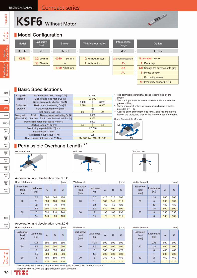
79
ELECTRIC ACTUATORS Compact seriesP
rod
uct
Line
upTe
ch
nic
al
Ma
teri
als
KSF8
KSF4
KSF 10T
KSF10
KSF 6T
KSF 8T
KSF 10U
KSF 4U
KSF 5U
KSF 6U
KSF 8U
TNU/TJU
THC
Spec
ifica
tions
/ D
imen
sion
sM
odel
C
onfig
urat
ion
Fea
ture
sELECTRIC ACTUATORS Compact series
KSF5
ELECTRIC ACTUATORS Compact series
KSF6
KSF 5T
ELECTRIC ACTUATORS Compact series
KSF6 Without Motor
Model Configuration
ModelBall screw
leadStroke With/without motor
Intermediate flange
Option
KSF6 - 20 - 0750 - 0 - AV - GR-6
KSF6 20: 20 mm 0050: 50 mm 0: Without motor A0: Without intermediate flange No symbol : None
30: 30 mm to 1: With motor AV T : Back tap
1300: 1300 mm AY GR : Change the cover color to gray
AU 6 : Photo sensor
J : Proximity sensor
M : Proximity sensor (PNP)
Basic SpecificationsLM guide portion
Basic dynamic load rating C [N] 17,400Basic static load rating C0 [N] 33,000
Ball screw portion
Basic dynamic load rating Ca [N] 3,400 3,230Basic static load rating C0a [N] 8,070 6,570
Screw shaft diameter [mm] 15Ball screw lead [mm] 20 30
Bearing portion (Fixed side)
Axial direction
Basic dynamic load rating Ca [N] 6,650Static permissible load P0a [N] 3,250
Permissible rotational speed 1[min-1] 3,000Starting torque 2 [N·cm] 6.2 8.3
Positioning repeatability 3 [mm] ±0.010Lost motion 3 [mm] 0.1
Permissible input torque [N·m] 3.1Static permissible moment 4 [N·m] MA: 330 MB: 216 MC: 188
Permissible Overhang Length 5
Horizontal use Wall use Vertical use
CB
A
A B
C
A C
Acceleration and deceleration rate: 1.0 GHorizontal mount [mm] Wall mount [mm] Vertical mount [mm]
Ball screw lead [mm]
Load mass [kg]
A B CBall screw
lead [mm]
Load mass [kg]
A B CBall screw
lead [mm]
Load mass [kg]
A C
20
5.5 600 340 470
20
5.5 420 310 600
20
2.5 600 600
11 330 160 230 11 180 140 310 5 300 300
22 140 70 110 22 60 50 120 10 130 130
30
3.5 600 430 480
30
3.5 430 400 600
30
1.5 600 600
7 320 210 240 7 190 180 290 3 350 350
14 140 90 120 14 70 70 110 6 160 160
Acceleration and deceleration rate: 2.0 GHorizontal mount [mm] Wall mount [mm] Vertical mount [mm]
Ball screw lead [mm]
Load mass [kg]
A B CBall screw
lead [mm]
Load mass [kg]
A B CBall screw
lead [mm]
Load mass [kg]
A C
20
1.25 600 600 600
20
1.25 600 600 600
20
0.75 600 600
2.5 600 600 600 2.5 600 600 600 1.5 600 600
5 480 370 420 5 360 350 470 3 460 460
30
1.5 600 600 600
30
1.5 600 600 600
30
1 600 600
3 490 500 440 3 380 470 480 2 460 460
6 230 240 220 6 170 210 210 4 210 2105 This value is the overhang length whose running life is 20,000 km for each direction.
A permissible value of the applied load in each direction.
1 The permissible rotational speed is restricted by the stroke.
2 The starting torque represents values when the standard grease is filled.
3 These represent values when measured using a motor provided by THK.
4 Applied point of moment load for MA and MC are the top face of the table, and that for MB is the center of the table.
MB
MA
MC
Static Permissible Moment
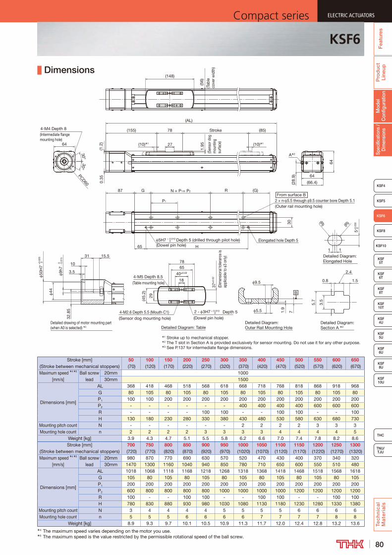
80
ELECTRIC ACTUATORSCompact series
Pro
duc
t Li
neup
Tec
hn
ica
l M
ate
ria
ls
THC
TNU/TJU
KSF8
KSF4
KSF 10T
KSF10
KSF 6T
KSF 8T
KSF 10U
KSF 4U
KSF 5U
KSF 6U
KSF 8U
Spec
ifica
tions
/ D
imen
sion
sM
odel
C
onfig
urat
ion
Fea
ture
s
ELECTRIC ACTUATORSCompact series
KSF5
ELECTRIC ACTUATORSCompact series
KSF6
KSF5T
ELECTRIC ACTUATORSCompact series
Dimensions
Detailed Diagram: Section A 2
Detailed Diagram: Outer Rail Mounting HoleDetailed Diagram: Table
Detailed drawing of motor mounting part (when A0 is selected) 3
B
1 Stroke up to mechanical stopper.2 The T slot in Section A is provided exclusively for sensor mounting. Do not use it for any other purpose.3 See P.137 for intermediate flange dimensions.
64
64
27
(85)
(AL)
(155)
(10) 1
Stroke
PCD60
1.95
(Sen
sor d
og
mou
ntin
g su
rface
)
30
G R (G)
64
30° 30°
4-M4 Depth 8(Intermediate flange mounting hole)
37±
0.02
(Dim
ensio
nal t
oler
ance
is
appl
icab
le to
3
only)
65
40±0.02
78
2 - 3H7 + 0.010 0 Depth 5
(Dowel pin hole)
P1
N × P1= P2 87
4-M5 Depth 8.5(Table mounting hole)
18
4-M2.6 Depth 5.5 (Mouth C1)(Sensor dog mounting hole)
(10) 1
(148)
A 2
71.9
5.5
9.5
(1.2
)0.
35
(28.
9)
29
(45.
2)
(Tab
le
cove
r wid
th)
(56)
Detailed Diagram: Elongated Hole
Elongated hole Depth 5 5H7 + 0.012 0 Depth 5 (drilled through pilot hole)
(R) (R)
5+0.
030
0
11H65
From surface B2 × n- 5.5 through 9.5 counter bore Depth 5.1(Outer rail mounting hole)
(66.4)
78
2.4
0.8
5.7
3.5
1.5
3.5
10
50H
7 0+0.
025
44
9h7
- 0.
015
0
15.531
32.8
5
(Dowel pin hole)
Stroke [mm] (Stroke between mechanical stoppers)
50 (70)
100 (120)
150 (170)
200 (220)
250 (270)
300 (320)
350 (370)
400 (420)
450 (470)
500 (520)
550 (570)
600 (620)
650 (670)
Maximum speed 4 5 [mm/s]
Ball screw lead
20mm 100030mm 1500
Dimensions [mm]
AL 368 418 468 518 568 618 668 718 768 818 868 918 968G 80 105 80 105 80 105 80 105 80 105 80 105 80P1 100 100 200 200 200 200 200 200 200 200 200 200 200P2 - - - - - - 400 400 400 400 600 600 600R - - - - 100 100 - - 100 100 - - 100H 130 180 230 280 330 380 430 480 530 580 630 680 730
Mounting pitch count N - - - - - - 2 2 2 2 3 3 3Mounting hole count n 2 2 2 2 3 3 3 3 4 4 4 4 5
Weight [kg] 3.9 4.3 4.7 5.1 5.5 5.8 6.2 6.6 7.0 7.4 7.8 8.2 8.6Stroke [mm]
(Stroke between mechanical stoppers)700
(720)750
(770)800
(820)850
(870)900
(920)950
(970)1000
(1020)1050
(1070)1100
(1120)1150
(1170)1200
(1220)1250
(1270)1300
(1320)Maximum speed 4 5
[mm/s]Ball screw
lead20mm 980 870 770 690 630 570 520 470 430 400 370 340 32030mm 1470 1300 1160 1040 940 850 780 710 650 600 550 510 480
Dimensions [mm]
AL 1018 1068 1118 1168 1218 1268 1318 1368 1418 1468 1518 1568 1618G 105 80 105 80 105 80 105 80 105 80 105 80 105P1 200 200 200 200 200 200 200 200 200 200 200 200 200P2 600 800 800 800 800 1000 1000 1000 1000 1200 1200 1200 1200R 100 - - 100 100 - - 100 100 - - 100 100H 780 830 880 930 980 1030 1080 1130 1180 1230 1280 1330 1380
Mounting pitch count N 3 4 4 4 4 5 5 5 5 6 6 6 6Mounting hole count n 5 5 5 6 6 6 6 7 7 7 7 8 8
Weight [kg] 8.9 9.3 9.7 10.1 10.5 10.9 11.3 11.7 12.0 12.4 12.8 13.2 13.64 The maximum speed varies depending on the motor you use.5 The maximum speed is the value restricted by the permissible rotational speed of the ball screw.
KSF6

81
ELECTRIC ACTUATORS Compact seriesP
rod
uct
Line
upTe
ch
nic
al
Ma
teri
als
KSF8
KSF4
KSF 10T
KSF10
KSF 6T
KSF 8T
KSF 10U
KSF 4U
KSF 5U
KSF 6U
KSF 8U
TNU/TJU
THC
Spec
ifica
tions
/ D
imen
sion
sM
odel
C
onfig
urat
ion
Fea
ture
sELECTRIC ACTUATORS Compact series
KSF5
ELECTRIC ACTUATORS Compact series
KSF6
KSF 5T
ELECTRIC ACTUATORS Compact series
KSF6R Without Motor
Model Configuration
ModelBall screw
leadStroke
With/without motor
Motor mounting plate
Motor shaft diameter
Motor shaft fixing method
Option
KSF6R - 20 - 0050 - 0 - WV - 14 M - MR-T-GR
KSF6R 20: 20 mm 0050: 50 mm 0: Without motor WV 11: 11 mm D : D-cut MR : Motor right wrap30: 30 mm to 1: With motor WY 14: 14 mm K : Key ML : Motor left wrap
1300: 1300 mm M : Friction tightening MD : Motor down wrap T : Back tap GR : Change the cover color to gray 6 : Photo sensor J : Proximity sensor M : Proximity sensor (PNP)
Basic SpecificationsLM guide portion
Basic dynamic load rating C [N] 17,400Basic static load rating C0 [N] 33,000
Ball screw portion
Basic dynamic load rating Ca [N] 3,400 3,230Basic static load rating C0a [N] 8,070 6,570
Screw shaft diameter [mm] 15Ball screw lead [mm] 20 30
Bearing portion (Fixed side)
Axial direction
Basic dynamic load rating Ca [N] 6,650Static permissible load P0a [N] 3,250
Permissible rotational speed 1[min-1] 3,000Starting torque 2 [N·cm] 6.2 8.3
Positioning repeatability 3 [mm] ±0.010Lost motion 3 [mm] 0.1
Permissible input torque [N·m] 2.2Static permissible moment 4 [N·m] MA: 330 MB: 216 MC: 188
Permissible Overhang Length 5
Horizontal use Wall use Vertical use
CB
A
A B
C
A C
Acceleration and deceleration rate 1.0 GHorizontal mount [mm] Wall mount [mm] Vertical mount [mm]
Ball screw lead [mm]
Load mass [kg]
A B CBall screw
lead [mm]
Load mass [kg]
A B CBall screw
lead [mm]
Load mass [kg]
A C
20
4.75 600 390 540
20
4.75 490 370 600
20
2.25 600 600
9.5 390 190 270 9.5 220 160 370 4.5 330 330
19 170 90 130 19 80 60 150 9 150 150
30
2.75 600 550 600
30
2.75 560 520 600
30
1.25 600 600
5.5 410 270 310 5.5 250 240 390 2.5 430 430
11 180 120 150 11 100 100 160 5 200 200
Acceleration and deceleration rate 2.0 GHorizontal mount [mm] Wall mount [mm] Vertical mount [mm]
Ball screw lead [mm]
Load mass [kg]
A B CBall screw
lead [mm]
Load mass [kg]
A B CBall screw
lead [mm]
Load mass [kg]
A C
20
1 600 600 600
20
1 600 600 600
20
0.38 600 600
2 600 600 600 2 600 600 600 0.75 600 600
4 600 470 520 4 460 440 600 1.5 600 600
30
1 600 600 600
30
1 600 600 600
30
0.625 600 600
2 600 600 600 2 590 600 600 1.25 600 600
4 360 370 330 4 270 340 350 2.5 360 3605 This value is the overhang length whose running life is 20,000 km for each direction.
A permissible value of the applied load in each direction.
1 The permissible rotational speed is restricted by the stroke.
2 The starting torque represents values when the standard grease is filled.
3 These represent values when measured using a motor provided by THK.
4 Applied point of moment load for MA and MC are the top face of the table, and that for MB is the center of the table.
MB
MA
MC
Static Permissible Moment
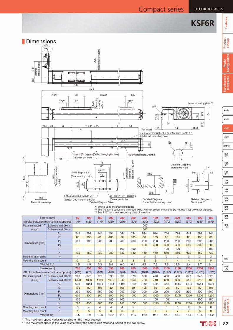
82
ELECTRIC ACTUATORSCompact series
Pro
duc
t Li
neup
Tec
hn
ica
l M
ate
ria
ls
THC
TNU/TJU
KSF8
KSF4
KSF 10T
KSF10
KSF 6T
KSF 8T
KSF 10U
KSF 4U
KSF 5U
KSF 6U
KSF 8U
Spec
ifica
tions
/ D
imen
sion
sM
odel
C
onfig
urat
ion
Fea
ture
s
ELECTRIC ACTUATORSCompact series
KSF5
ELECTRIC ACTUATORSCompact series
KSF6
KSF5T
ELECTRIC ACTUATORSCompact series
Dimensions
1 Stroke up to mechanical stopper.2 The T slot in Section A is provided exclusively for sensor mounting. Do not use it for any other purpose.3 See P.137 for motor mounting plate dimensions.
(75)
(Dist
ance
be
twee
n sh
afts
)
(29)
148
27
(85)Stroke78
(10) 1 (10) 1
(131)
(AL)
(56)
(Tab
le c
over
wid
th)
1.95
(Sen
sor d
og
mou
ntin
g su
rface
)
(26) 7
(40)
Motor down wrap
From surface B
30
(G)30 N × P 1 = P 2 R
H
2 × n- 5.5 through 9.5 counter bore Depth 5.1(Outer rail mounting hole)
65
P1
G
Elongated hole Depth 55H7 Depth 5 (Drilled through pilot hole)
(33)
0+0.012
B
Detailed Diagram: TableDetailed Diagram: Outer Rail Mounting Hole
Detailed Diagram: Section A 2
71.9
5.5
9.5
29
37±
0.02
(Dim
ensio
nal
tole
ranc
e is
appl
icab
le to
3
only)
65
40±0.02
2 - 3H7 + 0.010 0 Depth 5
(Dowel pin hole)
4-M5 Depth 8.5
(Table mounting hole) 18
4-M2.6 Depth 5.5 (Mouth C1)
(Sensor dog mounting hole)
(45.
2)
Detailed Diagram: Elongated Hole
1 1
5+0.
030
0
(R)(R)
78
2.4
0.8
5.7
3.5
1.5
(83.
2)
(75)
(Dis
tanc
e b
etw
een
sha
fts)
(1.7
)14
5
(60)
(1.7
)
(60)
148
64
64
(28.
9)
(2.8
)
(1.2)
30
(1.7)
A 2
Motor mounting plate 3
(Dowel pin hole)
Stroke [mm] (Stroke between mechanical stoppers)
50 (70)
100 (120)
150 (170)
200 (220)
250 (270)
300 (320)
350 (370)
400 (420)
450 (470)
500 (520)
550 (570)
600 (620)
650 (670)
Maximum speed 4 5 [mm/s]
Ball screw lead: 20 mm 1000Ball screw lead: 30 mm 1500
Dimensions [mm]
AL 344 394 444 494 544 594 644 694 744 794 844 894 944G 80 105 80 105 80 105 80 105 80 105 80 105 80P1 100 100 200 200 200 200 200 200 200 200 200 200 200P2 - - - - - - 400 400 400 400 600 600 600R - - - - 100 100 - - 100 100 - - 100H 130 180 230 280 330 380 430 480 530 580 630 680 730
Mounting pitch count N - - - - - - 2 2 2 2 3 3 3Mounting hole count n 2 2 2 2 3 3 3 3 4 4 4 4 5
Weight [kg] 4.5 4.9 5.3 5.6 6.0 6.4 6.8 7.2 7.6 8.0 8.4 8.7 9.1Stroke [mm]
(Stroke between mechanical stoppers)700
(720)750
(770)800
(820)850
(870)900
(920)950
(970)1000
(1020)1050
(1070)1100
(1120)1150
(1170)1200
(1220)1250
(1270)1300
(1320)Maximum speed 4 5
[mm/s]Ball screw lead: 20 mm 980 870 770 690 630 570 520 470 430 400 370 340 320Ball screw lead: 30 mm 1470 1300 1160 1040 940 850 780 710 650 600 550 510 480
Dimensions [mm]
AL 994 1044 1094 1144 1194 1244 1294 1344 1394 1444 1494 1544 1594G 105 80 105 80 105 80 105 80 105 80 105 80 105P1 200 200 200 200 200 200 200 200 200 200 200 200 200P2 600 800 800 800 800 1000 1000 1000 1000 1200 1200 1200 1200R 100 - - 100 100 - - 100 100 - - 100 100H 780 830 880 930 980 1030 1080 1130 1180 1230 1280 1330 1380
Mounting pitch count N 3 4 4 4 4 5 5 5 5 6 6 6 6Mounting hole count n 5 5 5 6 6 6 6 7 7 7 7 8 8
Weight [kg] 9.5 9.9 10.3 10.7 11.1 11.5 11.8 12.2 12.6 13.0 13.4 13.8 14.24 The maximum speed varies depending on the motor you use.5 The maximum speed is the value restricted by the permissible rotational speed of the ball screw.
KSF6R

83
ELECTRIC ACTUATORS Compact seriesP
rod
uct
Line
upTe
ch
nic
al
Ma
teri
als
KSF4
KSF10
KSF 5T
KSF 6T
KSF 8T
KSF 10U
KSF 4U
KSF 5U
KSF 6U
KSF 8U
TNU/TJU
THC
Spec
ifica
tions
/ D
imen
sion
sM
odel
C
onfig
urat
ion
Fea
ture
sELECTRIC ACTUATORS Compact series
KSF5
KSF6
ELECTRIC ACTUATORS Compact series
KSF8
KSF 10T
ELECTRIC ACTUATORS Compact series
KSF8 Without Motor
Model Configuration
ModelBall screw
leadStroke With/without motor
Intermediate flange
Option
KSF8 - 20 - 0800 - 0 - AV - GR-6
KSF8 20: 20 mm 0100: 100 mm 0: Without motor A0: Without intermediate flange No symbol : None
40: 40 mm to 1: With motor AV T : Back tap1500: 1500 mm AY GR : Change the cover color to gray
AU 6 : Photo sensor J : Proximity sensor M : Proximity sensor (PNP)
Basic SpecificationsLM guide portion
Basic dynamic load rating C [N] 32,400Basic static load rating C0 [N] 63,500
Ball screw portion
Basic dynamic load rating Ca [N] 4,030 3,750Basic static load rating C0a [N] 10,540 8,870
Screw shaft diameter [mm] 20Ball screw lead [mm] 20 40
Bearing portion (Fixed side)
Axial direction
Basic dynamic load rating Ca [N] 7,600Static permissible load P0a [N] 4,000
Permissible rotational speed 1[min-1] 3,000Starting torque 2 [N·cm] 12
Positioning repeatability 3 [mm] ±0.010Lost motion 3 [mm] 0.1
Permissible input torque [N·m] 7.1Static permissible moment 4 [N·m] MA: 730 MB: 437 MC: 387
Permissible Overhang Length 5
Horizontal use Wall use Vertical use
CB
A
A B
C
A C
Acceleration and deceleration rate 1.0 GHorizontal mount [mm] Wall mount [mm] Vertical mount [mm]
Ball screw lead [mm]
Load mass [kg]
A B CBall screw
lead [mm]
Load mass [kg]
A B CBall screw
lead [mm]
Load mass [kg]
A C
20
10.75 730 350 510
20
10.75 450 330 710
20
5 630 630
21.5 340 160 250 21.5 200 190 420 10 290 290
43 140 70 120 43 70 50 120 20 130 130
40
4 800 800 770
40
4 710 780 800
40
2 800 800
8 500 390 390 8 330 360 480 4 500 500
16 220 180 200 16 140 160 200 8 230 230
Acceleration and deceleration rate 2.0 GHorizontal mount [mm] Wall mount [mm] Vertical mount [mm]
Ball screw lead [mm]
Load mass [kg]
A B CBall screw
lead [mm]
Load mass [kg]
A B CBall screw
lead [mm]
Load mass [kg]
A C
20
1.5 800 800 800
20
1.5 800 800 800
20
0.75 800 800
3 800 800 800 3 800 800 800 1.5 800 800
6 650 500 560 6 500 470 640 3 740 740
40
1.75 800 800 800
40
1.75 800 800 800
40
1.25 800 800
3.5 750 800 670 3.5 600 800 740 2.5 680 680
7 350 450 340 7 280 420 340 5 320 3205 This value is the overhang length whose running life is 20,000 km for each direction.
A permissible value of the applied load in each direction.
1 The permissible rotational speed is restricted by the stroke.
2 The starting torque represents values when the standard grease is filled.
3 These represent values when measured using a motor provided by THK.
4 Applied point of moment load for MA and MC are the top face of the table, and that for MB is the center of the table.
MB
MA
MC
Static Permissible Moment

84
ELECTRIC ACTUATORSCompact series
Pro
duc
t Li
neup
Tec
hn
ica
l M
ate
ria
ls
THC
TNU/TJU
KSF4
KSF10
KSF 5T
KSF 6T
KSF 8T
KSF 10U
KSF 4U
KSF 5U
KSF 6U
KSF 8U
Spec
ifica
tions
/ D
imen
sion
sM
odel
C
onfig
urat
ion
Fea
ture
s
ELECTRIC ACTUATORSCompact series
KSF5
KSF6
ELECTRIC ACTUATORSCompact series
KSF8
KSF 10T
ELECTRIC ACTUATORSCompact series
Dimensions
From surface B
Detailed drawing of motor mounting part (when A0 is selected) 3
1 Stroke up to mechanical stopper.2 The T slot in Section A is provided exclusively for sensor mounting. Do not use it for any other purpose.3 See P.138 for intermediate flange dimensions.
(168) Stroke
84
(86.4)
68
(0.7
)1
28.4
(10) 1
(99)
Elongated hole Depth 5
46
H
5H7 +0.0120 Depth 5 (drilled through pilot hole)
(AL)
35
(G)N × 200G93
(10) 1
120
200
10
(199)
2 × n - 6.6 through 11 counter bore Depth 6.3(Outer rail mounting hole)
4.4
(Sen
sor d
og
mou
ntin
g su
rface
)
(74)
(Tab
le c
over
wid
th)
(36)
12h7
0 -0.0
18
11
14
50H
7+
0.02
50
37
17
3.5
44
31
A 2
30°30°
4-M4 Depth 8(Intermediate flange mounting hole)
PCD60
84
Detailed Diagram: Elongated Hole
Detailed Diagram: Section A 2
Detailed Diagram: Outer Rail Mounting HoleDetailed Diagram: Table
B
5.7
3.5
1.5
2.4
0.8
3.7 106.6
11
70±0.02
2- 5H7 +0.0120 Depth 10
(Dowel pin hole)4-M3 Depth 6 (Mouth C1)
(Sensor dog mounting hole)
4-M6 Depth 12(Table mounting hole)
53±
0.02
(Dim
ensi
onal
tole
ranc
e is
ap
plic
able
to
5 on
ly)
10
100
11
(63) 43
(R)
(R) 5+
0.03
0 0
120
(Dowel pin hole)
Stroke [mm] (Stroke between mechanical stoppers)
100 (120)
200 (220)
300 (320)
400 (420)
500 (520)
600 (620)
700 (720)
800 (820)
900 (920)
1000 (1020)
1100 (1120)
1200 (1220)
1300 (1320)
1400 (1420)
1500 (1520)
Maximum speed 4 5 [mm/s]
Ball screw lead: 20 mm 1000 970 790 660 550 470 410 360 320Ball screw lead: 40 mm 2000 1940 1580 1320 1110 950 830 720 640
Dimensions [mm]AL 487 587 687 787 887 987 1087 1187 1287 1387 1487 1587 1687 1787 1887G 85 135 85 135 85 135 85 135 85 135 85 135 85 135 85H 300 400 500 600 700 800 900 1000 1100 1200 1300 1400 1500 1600 1700
Mounting pitch count N 1 1 2 2 3 3 4 4 5 5 6 6 7 7 8Mounting hole count n 2 2 3 3 4 4 5 5 6 6 7 7 8 8 9
Weight [kg] 8.1 9.4 10.7 12.0 13.3 14.6 15.9 17.2 18.5 19.8 21.1 22.4 23.7 25.0 26.34 The maximum speed varies depending on the motor you use.5 The maximum speed is the value restricted by the permissible rotational speed of the ball screw.
KSF8

85
ELECTRIC ACTUATORS Compact seriesP
rod
uct
Line
upTe
ch
nic
al
Ma
teri
als
KSF4
KSF10
KSF 5T
KSF 6T
KSF 8T
KSF 10U
KSF 4U
KSF 5U
KSF 6U
KSF 8U
TNU/TJU
THC
Spec
ifica
tions
/ D
imen
sion
sM
odel
C
onfig
urat
ion
Fea
ture
sELECTRIC ACTUATORS Compact series
KSF5
KSF6
ELECTRIC ACTUATORS Compact series
KSF8
KSF 10T
ELECTRIC ACTUATORS Compact series
KSF8R Without Motor
Model Configuration
ModelBall screw
leadStroke
With/without motor
Motor mounting plate
Motor shaft diameter
Motor shaft fixing method
Option
KSF8R - 20 - 0800 - 0 - WV - 14 M - MR-T-GR
KSF8R 20: 20 mm 0100: 100 mm 0: Without motor WV 14: 14 mm M: Friction tightening MR : Motor right wrap40: 40 mm to 1: With motor WY ML : Motor left wrap
1500: 1500 mm MD : Motor down wrap T : Back tap GR : Change the cover color to gray 6 : Photo sensor J : Proximity sensor M : Proximity sensor (PNP)
Basic SpecificationsLM guide portion
Basic dynamic load rating C [N] 32,400Basic static load rating C0 [N] 63,500
Ball screw portion
Basic dynamic load rating Ca [N] 4,030 3,750Basic static load rating C0a [N] 10,540 8,870
Screw shaft diameter [mm] 20Ball screw lead [mm] 20 40
Bearing portion (Fixed side)
Axial directionBasic dynamic load rating Ca [N] 7,600Static permissible load P0a [N] 4,000
Permissible rotational speed 1[min-1] 3,000Starting torque 2 [N·cm] 12
Positioning repeatability 3 [mm] ±0.010Lost motion 3 [mm] 0.1
Permissible input torque [N·m] 4.5Static permissible moment 4 [N·m] MA: 730 MB: 437 MC: 387
Permissible Overhang Length 5
Horizontal use Wall use Vertical use
CB
A
A B
C
A C
Acceleration and deceleration rate 1.0 GHorizontal mount [mm] Wall mount [mm] Vertical mount [mm]
Ball screw lead [mm]
Load mass [kg]
A B CBall screw
lead [mm]
Load mass [kg]
A B CBall screw
lead [mm]
Load mass [kg]
A C
20
10.25 800 520 670
20
10.25 620 490 800
20
5 630 630
20.5 520 250 330 20.5 280 220 500 10 290 290
41 230 110 160 41 110 90 210 20 130 130
40
4 800 800 770
40
4 710 780 800
40
2 800 800
8 500 390 390 8 330 360 480 4 500 500
16 220 180 200 16 140 160 200 8 230 230
Acceleration and deceleration rate 2.0 GHorizontal mount [mm] Wall mount [mm] Vertical mount [mm]
Ball screw lead [mm]
Load mass [kg]
A B CBall screw
lead [mm]
Load mass [kg]
A B CBall screw
lead [mm]
Load mass [kg]
A C
20
1.5 800 800 800
20
1.5 800 800 800
20
0.75 800 800
3 800 800 800 3 800 800 800 1.5 800 800
6 650 500 560 6 500 470 640 3 740 740
40
1.75 800 800 800
40
1.75 800 800 800
40
1.25 800 800
3.5 750 800 670 3.5 600 800 740 2.5 680 680
7 350 450 340 7 280 420 340 5 320 3205 This value is the overhang length whose running life is 20,000 km for each direction.
A permissible value of the applied load in each direction.
1 The permissible rotational speed is restricted by the stroke.
2 The starting torque represents values when the standard grease is filled.
3 These represent values when measured using a motor provided by THK.
4 Applied point of moment load for MA and MC are the top face of the table, and that for MB is the center of the table.
MB
MA
MC
Static Permissible Moment
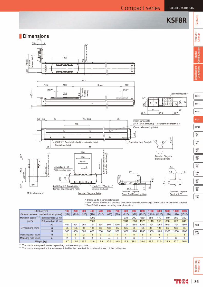
86
ELECTRIC ACTUATORSCompact series
Pro
duc
t Li
neup
Tec
hn
ica
l M
ate
ria
ls
THC
TNU/TJU
KSF4
KSF10
KSF 5T
KSF 6T
KSF 8T
KSF 10U
KSF 4U
KSF 5U
KSF 6U
KSF 8U
Spec
ifica
tions
/ D
imen
sion
sM
odel
C
onfig
urat
ion
Fea
ture
s
ELECTRIC ACTUATORSCompact series
KSF5
KSF6
ELECTRIC ACTUATORSCompact series
KSF8
KSF 10T
ELECTRIC ACTUATORSCompact series
Dimensions
1 Stroke up to mechanical stopper.2 The T slot in Section A is provided exclusively for sensor mounting. Do not use it for any other purpose.3 See P.138 for motor mounting plate dimensions.
Stroke
(0.7
)1
28.4
(10) 1
(99)
(AL)
(10) 1
120(145)
(199)
4.4
(Sen
sor d
og
mou
ntin
g s
urfa
ce)
(74)
(Tab
le c
over
wid
th)
(29)
(103
.5)
(Dist
ance
be
twee
n sh
afts
)
(29)
(43)
7
From surface B
Motor down wrap
Elongated hole Depth 5
46
H
5H7+0.012 0 Depth 5 (drilled through pilot hole)
35
(G)N × 200G
200 2 × n - 6.6 through 11 counter bore Depth 6.3
(Outer rail mounting hole)
34(36)
Detailed Diagram: Elongated Hole
Detailed Diagram: Section A 2
Detailed Diagram: Outer Rail Mounting HoleDetailed Diagram: Table
B
5.7
3.5
1.5
2.4
0.8
3.7 106.6
11
70±0.02
2- 5H7 +0.0120 Depth 10
(Dowel pin hole)4-M3 Depth 6 (Mouth C1)(Sensor dog mounting hole)
4-M6 Depth 12(Table mounting hole)
53±
0.02
(Dim
ensi
onal
tol
eran
ce is
ap
plic
able
to
5 on
ly)
10
100
11
(63) 43
(R)
(R) 5+
0.03
0 0
120
(1.7
)
(103
.5)
(Dis
tanc
e be
twee
n sh
afts
)
(107
.5)17
3.5
(1.7
) (60)
(1.7)
(7)
37
68(60)
(1.2) 186.5
84
(36)
A 2
Motor mounting plate 3
(Dowel pin hole)
Stroke [mm] (Stroke between mechanical stoppers)
100 (120)
200 (220)
300 (320)
400 (420)
500 (520)
600 (620)
700 (720)
800 (820)
900 (920)
1000 (1020)
1100 (1120)
1200 (1220)
1300 (1320)
1400 (1420)
1500 (1520)
Maximum speed 4 5 [mm/s]
Ball screw lead: 20 mm 1000 970 790 660 550 470 410 360 320Ball screw lead: 40 mm 2000 1940 1580 1320 1110 950 830 720 640
Dimensions [mm]AL 464 564 664 764 864 964 1064 1164 1264 1364 1464 1564 1664 1764 1864G 85 135 85 135 85 135 85 135 85 135 85 135 85 135 85H 300 400 500 600 700 800 900 1000 1100 1200 1300 1400 1500 1600 1700
Mounting pitch count N 1 1 2 2 3 3 4 4 5 5 6 6 7 7 8Mounting hole count n 2 2 3 3 4 4 5 5 6 6 7 7 8 8 9
Weight [kg] 8.7 10.0 11.3 12.6 13.9 15.2 16.5 17.8 19.1 20.4 21.7 23.0 24.3 25.6 26.94 The maximum speed varies depending on the motor you use.5 The maximum speed is the value restricted by the permissible rotational speed of the ball screw.
KSF8R
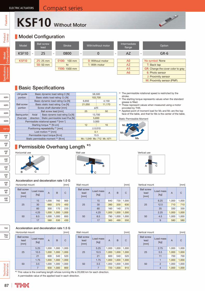
87
ELECTRIC ACTUATORS Compact seriesP
rod
uct
Line
upTe
ch
nic
al
Ma
teri
als
KSF8
KSF4
KSF 10T
KSF 5T
KSF 6T
KSF 8T
KSF 10U
KSF 4U
KSF 5U
KSF 8U
TNU/TJU
THC
Spec
ifica
tions
/ D
imen
sion
sM
odel
C
onfig
urat
ion
Fea
ture
sELECTRIC ACTUATORS Compact series
KSF5
KSF6
ELECTRIC ACTUATORS Compact series
KSF10
KSF 6U
ELECTRIC ACTUATORS Compact series
KSF10 Without Motor
Model Configuration
ModelBall screw
leadStroke With/without motor
Intermediate flange
Option
KSF10 - 25 - 0800 - 0 - AZ - GR-6
KSF10 25: 25 mm 0100: 100 mm 0: Without motor A0 No symbol : None
50: 50 mm to 1: With motor AZ T : Back tap1500: 1500 mm A5 GR : Change the cover color to gray
A6 6 : Photo sensor J : Proximity sensor M : Proximity sensor (PNP)
Basic SpecificationsLM guide portion
Basic dynamic load rating C [N] 58,500Basic static load rating C0 [N] 103,700
Ball screw portion
Basic dynamic load rating Ca [N] 6,650 4,150Basic static load rating C0a [N] 21,050 11,170
Screw shaft diameter [mm] 25Ball screw lead [mm] 25 50
Bearing portion (Fixed side)
Axial direction
Basic dynamic load rating Ca [N] 13,700Static permissible load P0a [N] 5,830
Permissible rotational speed 1[min-1] 3,000Starting torque 2 [N·cm] 12 16
Positioning repeatability 3 [mm] ±0.010Lost motion 3 [mm] 0.1
Permissible input torque [N·m] 15.5Static permissible moment 4 [N·m] MA: 1,049 MB: 712 MC: 671
Permissible Overhang Length 5
Horizontal use Wall use Vertical use
CB
A
A B
C
A C
Acceleration and deceleration rate 1.0 GHorizontal mount [mm] Wall mount [mm] Vertical mount [mm]
Ball screw lead [mm]
Load mass [kg]
A B CBall screw
lead [mm]
Load mass [kg]
A B CBall screw
lead [mm]
Load mass [kg]
A C
25
15 1,000 760 900
25
15 840 730 1,000
25
6.25 1,000 1,000
30 660 370 450 30 390 330 630 12.5 710 710
60 300 170 220 60 160 140 270 25 330 330
50
4.25 1,000 1,000 1,000
50
4.25 1,000 1,000 1,000
50
2.25 1,000 1,000
8.5 1,000 1,000 850 8.5 790 1,000 1,000 4.5 1,000 1,000
17 580 530 430 17 360 490 550 9 580 580
Acceleration and deceleration rate 1.5 GHorizontal mount [mm] Wall mount [mm] Vertical mount [mm]
Ball screw lead [mm]
Load mass [kg]
A B CBall screw
lead [mm]
Load mass [kg]
A B CBall screw
lead [mm]
Load mass [kg]
A C
25
5.25 1,000 1,000 1,000
25
5.25 1,000 1,000 1,000
25
2.75 1,000 1,000
10.5 1,000 1,000 1,000 10.5 1,000 1,000 1,000 5.5 1,000 1,000
21 600 540 520 21 600 540 520 11 700 700
50
1.75 1,000 1,000 1,000
50
1.75 1,000 1,000 1,000
50
1 1,000 1,000
3.5 1,000 1,000 1,000 3.5 1,000 1,000 1,000 2 1,000 1,000
7 930 1,000 800 7 720 1,000 910 4 1,000 1,0005 This value is the overhang length whose running life is 20,000 km for each direction.
A permissible value of the applied load in each direction.
1 The permissible rotational speed is restricted by the stroke.
2 The starting torque represents values when the standard grease is filled.
3 These represent values when measured using a motor provided by THK.
4 Applied point of moment load for MA and MC are the top face of the table, and that for MB is the center of the table.
MB
MA
MC
Static Permissible Moment

88
ELECTRIC ACTUATORSCompact series
Pro
duc
t Li
neup
Tec
hn
ica
l M
ate
ria
ls
THC
TNU/TJU
KSF8
KSF4
KSF 10T
KSF 5T
KSF 6T
KSF 8T
KSF 10U
KSF 4U
KSF 5U
KSF 8U
Spec
ifica
tions
/ D
imen
sion
sM
odel
C
onfig
urat
ion
Fea
ture
s
ELECTRIC ACTUATORSCompact series
KSF5
KSF6
ELECTRIC ACTUATORSCompact series
KSF10
KSF 6U
ELECTRIC ACTUATORSCompact series
Dimensions
2 The T slot in Section A is provided exclusively for sensor mounting. Do not use it for any other purpose.3 See P.139 for intermediate flange dimensions.
From surface B
Detailed drawing of motor mounting part (when A0 is selected) 3
N × 150
(10) 1
(53.
2)
50
90
(106.4)
104
2 × n- 9 through 14 counter bore Depth 8.4
H
(G)
5H7+0.0120 Depth 5 (drilled through pilot hole)
(Dowel pin hole)
Elongated hole Depth 5
G
150
115
28.4
(92)
(Tab
le c
over
wid
th
35
(10) 1
4.4
(Sen
sor d
og
mou
ntin
g s
urfa
ce)
140
A 2
(219)
(190) Stroke (107)4-M5 Depth 10(Intermediate flange mounting hole)
(106.4)
45°
PCD7
0
45°
0.5
(1)
(AL)
38
15 12
49
50H
7+
0.02
5 0
15h7
0 -0.0
18 16
1 Stroke up to mechanical stopper.
B
Detailed Diagram: Elongated Hole
Detailed Diagram: Section A 2
Detailed Diagram: Outer Rail Mounting HoleDetailed Diagram: Table
1 1
5+
0.03
00
(R)
(R)
4-M3 Depth 6 (Mouth C1.2)(Sensor dog mounting hole)
64±
0.02
(Dim
ensi
onal
tole
ranc
e is
ap
plic
able
to
5 on
ly)
2- 5H7 +0.012 0 Depth 10
(Dowel pin hole)
120
90 ±0.02
4-M8 Depth 15(Table mounting hole) 10
14
9 134.6
0.8
2.4
1.53.
5
5.7
140
48(80)
14
(Outer rail mounting hole)
Stroke [mm] (Stroke between mechanical stoppers)
100 (120)
200 (220)
300 (320)
400 (420)
500 (520)
600 (620)
700 (720)
800 (820)
900 (920)
1000 (1020)
1100 (1120)
1200 (1220)
1300 (1320)
1400 (1420)
1500 (1520)
Maximum speed 4 5 [mm/s]
Ball screw lead: 25 mm 1250 1050 890 760 660 580 510Ball screw lead: 50 mm 2500 2110 1790 1530 1330 1160 1030
Dimensions [mm]AL 537 637 737 837 937 1037 1137 1237 1337 1437 1537 1637 1737 1837 1937G 120 95 70 120 95 70 120 95 70 120 95 70 120 95 70H 320 420 520 620 720 820 920 1020 1120 1220 1320 1420 1520 1620 1720
Mounting pitch count N 1 2 3 3 4 5 5 6 7 7 8 9 9 10 11Mounting hole count n 2 3 4 4 5 6 6 7 8 8 9 10 10 11 12
Weight [kg] 14.7 16.8 18.8 20.9 22.9 25.0 27.0 29.1 31.2 33.2 35.3 37.3 39.4 41.5 43.54 The maximum speed varies depending on the motor you use.5 The maximum speed is the value restricted by the permissible rotational speed of the ball screw.
KSF10

89
ELECTRIC ACTUATORS Compact seriesP
rod
uct
Line
upTe
ch
nic
al
Ma
teri
als
KSF8
KSF4
KSF 10T
KSF 5T
KSF 6T
KSF 8T
KSF 10U
KSF 4U
KSF 5U
KSF 8U
TNU/TJU
THC
Spec
ifica
tions
/ D
imen
sion
sM
odel
C
onfig
urat
ion
Fea
ture
sELECTRIC ACTUATORS Compact series
KSF5
KSF6
ELECTRIC ACTUATORS Compact series
KSF10
KSF 6U
ELECTRIC ACTUATORS Compact series
KSF10R Without Motor
Model Configuration
ModelBall screw
leadStroke
With/without motor
Motor mounting plate
Motor shaft diameter
Motor shaft fixing method
Option
KSF10R - 25 - 0800 - 0 - WZ - 19 M - MR-T-GR
KSF10R 25: 25 mm 0100: 100 mm 0: Without motor WZ 16: 16 mm M: Friction tightening MR : Motor right wrap50: 50 mm to 1: With motor W5 19: 19 mm ML : Motor left wrap
1500: 1500 mm MD : Motor down wrap T : Back tap GR : Change the cover color to gray 6 : Photo sensor J : Proximity sensor M : Proximity sensor (PNP)
Basic SpecificationsLM guide portion
Basic dynamic load rating C [N] 58,500Basic static load rating C0 [N] 103,700
Ball screw portion
Basic dynamic load rating Ca [N] 6,650 4,150Basic static load rating C0a [N] 21,050 11,170
Screw shaft diameter [mm] 25Ball screw lead [mm] 25 50
Bearing portion (Fixed side)
Axial direction
Basic dynamic load rating Ca [N] 13,700Static permissible load P0a [N] 5,830
Permissible rotational speed 1[min-1] 3,000Starting torque 2 [N·cm] 12 16
Positioning repeatability 3 [mm] ±0.010Lost motion 3 [mm] 0.1
Permissible input torque [N·m] 8.5Static permissible moment 4 [N·m] MA: 1,049 MB: 712 MC: 671
Permissible Overhang Length 5
Horizontal use Wall use Vertical use
CB
A
A B
C
A C
Acceleration and deceleration rate 1.0 GHorizontal mount [mm] Wall mount [mm] Vertical mount [mm]
Ball screw lead [mm]
Load mass [kg]
A B CBall screw
lead [mm]
Load mass [kg]
A B CBall screw
lead [mm]
Load mass [kg]
A C
25
9.5 1000 1000 1000
25
9.5 1000 1000 1000
25
4.75 1000 1000
19 1000 600 710 19 650 560 1000 9.5 950 950
38 510 290 350 38 290 250 480 19 450 450
50
3 1000 1000 1000
50
3 1000 1000 1000
50
1.75 1000 1000
6 1000 1000 1000 6 1000 1000 1000 3.5 1000 1000
12 850 760 620 12 540 720 810 7 760 760
Acceleration and deceleration rate 1.5 GHorizontal mount [mm] Wall mount [mm] Vertical mount [mm]
Ball screw lead [mm]
Load mass [kg]
A B CBall screw
lead [mm]
Load mass [kg]
A B CBall screw
lead [mm]
Load mass [kg]
A C
25
2 1000 1000 1000
25
2 1000 1000 1000
25
0.75 1000 1000
4 1000 1000 1000 4 1000 1000 1000 1.5 1000 1000
8 1000 1000 1000 8 1000 1000 1000 3 1000 1000
50
1 1000 1000 1000
50
1 1000 1000 1000
50
0.75 1000 1000
2 1000 1000 1000 2 1000 1000 1000 1.5 1000 1000
4 1000 1000 1000 4 1000 1000 1000 3 1000 10005 This value is the overhang length whose running life is 20,000 km for each direction.
A permissible value of the applied load in each direction.
1 The permissible rotational speed is restricted by the stroke.
2 The starting torque represents values when the standard grease is filled.
3 These represent values when measured using a motor provided by THK.
4 Applied point of moment load for MA and MC are the top face of the table, and that for MB is the center of the table.
MB
MA
MC
Static Permissible Moment
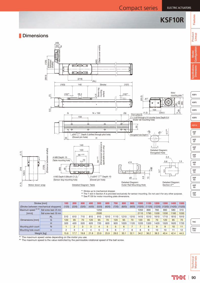
90
ELECTRIC ACTUATORSCompact series
Pro
duc
t Li
neup
Tec
hn
ica
l M
ate
ria
ls
THC
TNU/TJU
KSF8
KSF4
KSF 10T
KSF 5T
KSF 6T
KSF 8T
KSF 10U
KSF 4U
KSF 5U
KSF 8U
Spec
ifica
tions
/ D
imen
sion
sM
odel
C
onfig
urat
ion
Fea
ture
s
ELECTRIC ACTUATORSCompact series
KSF5
KSF6
ELECTRIC ACTUATORSCompact series
KSF10
KSF 6U
ELECTRIC ACTUATORSCompact series
Dimensions
3 See P.139 for motor mounting plate dimensions.
(92)
(Tab
le c
over
wid
th)
(219)(AL)
(38.
5)(1
20)
(Dis
tanc
e b
etw
een
shaf
ts)
8(32)(49)
(10) 1 (10) 128.44.
4(S
enso
r dog
m
ount
ing
surfa
ce)
140 Stroke (107)(163)
0.5
(1)
40(8
0)(9
)
(1.7)
(90)
229.5(1.2)104
(53.
2)
A 2
Motor down wrap
From surface BN × 150
50H
(G)
5H7+0.0120 Depth 5 (drilled through pilot hole)
(Dowel pin hole)Elongated hole Depth 5
G
150
35
(120
)
(Dis
tanc
e b
etw
een
shaf
ts)
(1.7
)(1
.7)
216
128.
5
B
Detailed Diagram: Elongated Hole
Detailed Diagram: Section A 2
Detailed Diagram: Outer Rail Mounting HoleDetailed Diagram: Table
1 1
5+
0.03
0 0(R)
(R)
4-M3 Depth 6 (Mouth C1.2)(Sensor dog mounting hole)
64±
0.02
(Dim
ensi
onal
tole
ranc
e is
ap
plic
able
to
5 on
ly)
2- 5H7 +0.012 0 Depth 10
(Dowel pin hole)
120
90 ±0.02
4-M8 Depth 15(Table mounting hole) 10
14
9 134.6
0.8
2.4
1.53.
5
5.7
140
48(80)
1 Stroke up to mechanical stopper.2 The T slot in Section A is provided exclusively for sensor mounting. Do not use it for any other purpose.
Motor mounting plate 3
2 × n- 9 through 14 counter bore Depth 8.4(Outer rail mounting hole)
Stroke [mm] (Stroke between mechanical stoppers)
100 (120)
200 (220)
300 (320)
400 (420)
500 (520)
600 (620)
700 (720)
800 (820)
900 (920)
1000 (1020)
1100 (1120)
1200 (1220)
1300 (1320)
1400 (1420)
1500 (1520)
Maximum speed 4 5 [mm/s]
Ball screw lead: 25 mm 1250 1050 890 760 660 580 510Ball screw lead: 50 mm 2500 2110 1790 1530 1330 1160 1030
Dimensions [mm]AL 510 610 710 810 910 1010 1110 1210 1310 1410 1510 1610 1710 1810 1910G 120 95 70 120 95 70 120 95 70 120 95 70 120 95 70H 320 420 520 620 720 820 920 1020 1120 1220 1320 1420 1520 1620 1720
Mounting pitch count N 1 2 3 3 4 5 5 6 7 7 8 9 9 10 11Mounting hole count n 2 3 4 4 5 6 6 7 8 8 9 10 10 11 12
Weight [kg] 15.6 17.7 19.8 21.8 23.9 25.9 28.0 30.1 32.1 34.2 36.2 38.3 40.4 42.4 44.54 The maximum speed varies depending on the motor you use.5 The maximum speed is the value restricted by the permissible rotational speed of the ball screw.
KSF10R

91
ELECTRIC ACTUATORS Compact seriesP
rod
uct
Line
upTe
ch
nic
al
Ma
teri
als
KSF4
KSF 10T
KSF10
KSF 6T
KSF 8T
KSF 10U
KSF 4U
KSF 5U
KSF 6U
KSF 8U
TNU/TJU
THC
Spec
ifica
tions
/ D
imen
sion
sM
odel
C
onfig
urat
ion
Fea
ture
sELECTRIC ACTUATORS Compact series
KSF5
KSF6
ELECTRIC ACTUATORS Compact series
KSF 5T
KSF8
ELECTRIC ACTUATORS Compact series
KSF5T Without Motor
Model Configuration
ModelBall screw
leadStroke With/without motor
Intermediate flange
Option
KSF5T - 10 - 0050 - 0 - AQ - T-6
KSF5T 10: 10 mm 0050: 50 mm 0: Without motor A0 No symbol : None
20: 20 mm to 1: With motor AP T : Back tap0900: 900 mm AQ 1 : Sensor rail only
AR 6 : Photo sensor J : Proximity sensor M : Proximity sensor (PNP) F : Sub-table iron specification
Basic SpecificationsLM guide portion
Basic dynamic load rating C [N] 10,200
Basic static load rating C0 [N] 17,900
Ball screw portion
Basic dynamic load rating Ca [N] 3,350 2,150
Basic static load rating C0a [N] 6,600 4,470
Screw shaft diameter [mm] 13
Ball screw lead [mm] 10 20
Bearing portion (Fixed side)
Axial direction
Basic dynamic load rating Ca [N] 6,100
Static permissible load P0a [N] 3,100
Permissible rotational speed 1[min-1] 3,000
Starting torque 2 [N·cm] 7
Positioning repeatability 3 [mm] ±0.010
Lost motion 3 [mm] 0.1
Permissible input torque [N·m] 1.8
Static permissible moment 4 5 [N·m] MA:103 (147) MB: 61 (137) MC: 80 (149)
Permissible Overhang Length 6
Horizontal use Wall use Vertical use
CB
A
A B
C
A C
Acceleration and deceleration rate - lead 10 mm: 0.5 G, lead 20 mm: 1.0 GHorizontal mount [mm] Wall mount [mm] Vertical mount [mm]
Ball screw lead [mm]
Load mass [kg]
A B CBall screw
lead [mm]
Load mass [kg]
A B CBall screw
lead [mm]
Load mass [kg]
A C
10
5 500 210 420
10
5 390 190 500
10
3.25 300 300
10 500 100 200 10 170 80 500 6.5 140 140
20 250 40 90 20 60 30 210 13 50 50
20
1.75 500 490 500
20
1.75 500 470 500
20
1.5 470 470
3.5 500 240 340 3.5 300 220 480 3 220 220
7 230 110 170 7 130 90 210 6 90 90
Acceleration and deceleration rate - lead 10 mm: 1.0 G, lead 20 mm: 2.0 GHorizontal mount [mm] Wall mount [mm] Vertical mount [mm]
Ball screw lead [mm]
Load mass [kg]
A B CBall screw
lead [mm]
Load mass [kg]
A B CBall screw
lead [mm]
Load mass [kg]
A C
10
3.75 500 280 500
10
3.75 490 260 500
10
2 500 500
7.5 460 130 260 7.5 220 120 450 4 230 230
15 210 60 120 15 90 40 190 8 100 100
20
1.25 500 500 500
20
1.25 500 500 500
20
0.75 500 500
2.5 440 340 380 2.5 330 320 430 1.5 410 410
5 200 160 190 5 150 140 190 3 190 1906 This value is the overhang length whose running life is 10,000 km (20,000 km for lead 20 mm) for each direction.
A permissible value of the applied load in each direction.
MB
MA
MC
Static Permissible Moment
1 The permissible rotational speed is restricted by the stroke.
2 The starting torque represents values when the standard grease is filled.
3 These represent values when measured using a motor provided by THK.
4 Applied point of moment load for MA and MC are the top face of the table, and that for MB is the center of the table.
5 ( ) shows the value for sub-table iron specifications.
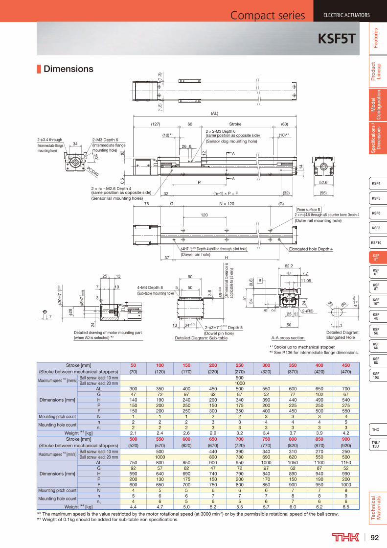
92
ELECTRIC ACTUATORSCompact series
Pro
duc
t Li
neup
Tec
hn
ica
l M
ate
ria
ls
THC
TNU/TJU
KSF4
KSF 10T
KSF10
KSF 6T
KSF 8T
KSF 10U
KSF 4U
KSF 5U
KSF 6U
KSF 8U
Spec
ifica
tions
/ D
imen
sion
sM
odel
C
onfig
urat
ion
Fea
ture
s
ELECTRIC ACTUATORSCompact series
KSF5
KSF6
ELECTRIC ACTUATORSCompact series
KSF 5T
KSF8
ELECTRIC ACTUATORSCompact series
KSF5T
Dimensions
Stroke [mm] (Stroke between mechanical stoppers)
50 (70)
100 (120)
150 (170)
200 (220)
250 (270)
300 (320)
350 (370)
400 (420)
450 (470)
Maximum speed 3 [mm/s]Ball screw lead: 10 mm 500Ball screw lead: 20 mm 1000
Dimensions [mm]
AL 300 350 400 450 500 550 600 650 700G 47 72 97 62 87 52 77 102 67H 140 190 240 290 340 390 440 490 540P 150 200 250 150 175 200 225 250 275F 150 200 250 300 350 400 450 500 550
Mounting pitch count N 1 1 1 2 2 3 3 3 4
Mounting hole countn 2 2 2 3 3 4 4 4 5n1 2 2 2 3 3 3 3 3 3
Weight 4 [kg] 2.1 2.4 2.6 2.9 3.2 3.4 3.7 3.9 4.2Stroke [mm]
(Stroke between mechanical stoppers)500 (520)
550 (570)
600 (620)
650 (670)
700 (720)
750 (770)
800 (820)
850 (870)
900 (920)
Maximum speed 3 [mm/s]Ball screw lead: 10 mm 500 440 390 340 310 270 250Ball screw lead: 20 mm 1000 890 780 690 620 550 500
Dimensions [mm]
AL 750 800 850 900 950 1000 1050 1100 1150G 92 57 82 47 72 97 62 87 52H 590 640 690 740 790 840 890 940 990P 200 130 175 150 200 170 150 190 200F 600 650 700 750 800 850 900 950 1000
Mounting pitch count N 4 5 5 6 6 6 7 7 8
Mounting hole countn 5 6 6 7 7 7 8 8 9n1 4 6 5 6 5 6 7 6 6
Weight 4 [kg] 4.4 4.7 5.0 5.2 5.5 5.7 6.0 6.2 6.53 The maximum speed is the value restricted by the motor rotational speed (at 3000 min-1) or by the permissible rotational speed of the ball screw.4 Weight of 0.1kg should be added for sub-table iron specifications.
14
Detailed drawing of motor mounting part (when A0 is selected) 2
A
A
Detailed Diagram: Sub-tableDetailed Diagram: Elongated Hole
1 Stroke up to mechanical stopper.2 See P.136 for intermediate flange dimensions.
A-A cross section
B
7
13
28
3
7
25
(1.3
)
24
30H
7+
0.02
1 0
10
8h7
0 -0.0
15
(1.3
)
37
N × 120
120
G
H
(G)
Elongated hole Depth 4
From surface B2 × n- 4.5 through 8 counter bore Depth 4(Outer rail mounting hole)
4H7 +0.012 0 Depth 4 (drilled through pilot hole)
(Dowel pin hole)
75
34
30°
PCD40
2-M3 Depth 6(Intermediate flange mounting hole)
2- 3.4 through(Intermediate flange mounting hole)
60
(10) 1 (10) 1
(63)Stroke(127)
32
P
(32)(n1-1) × P = F2 × n1 - M2.6 Depth 4 (same position as opposite side)(Sensor rail mounting holes)
(AL)
(R) (R)
1
4+
0.03
0 0
1
5
55±
0.02
(Dim
ensio
nal t
oler
ance
is
appl
icabl
e to
3
only)
50
3.6
4-M4 Depth 8(Sub-table mounting hole)
60
34±0.0213 2- 3H7 +0.0100 Depth 5
(Dowel pin hole)
26 8
12
2 × 2-M3 Depth 6 (same position as opposite side)(Sensor dog mounting hole)
52.6
(55)
12.5
50
27.7
51
662.2
11.05
47
25
34 24
2-(R3)
(0.8
)
(6)
0.5
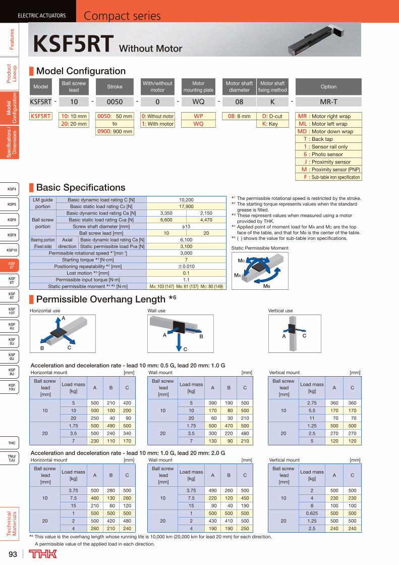
93
ELECTRIC ACTUATORS Compact seriesP
rod
uct
Line
upTe
ch
nic
al
Ma
teri
als
KSF4
KSF 10T
KSF10
KSF 6T
KSF 8T
KSF 10U
KSF 4U
KSF 5U
KSF 6U
KSF 8U
TNU/TJU
THC
Spec
ifica
tions
/ D
imen
sion
sM
odel
C
onfig
urat
ion
Fea
ture
sELECTRIC ACTUATORS Compact series
KSF5
KSF6
ELECTRIC ACTUATORS Compact series
KSF 5T
KSF8
ELECTRIC ACTUATORS Compact series
KSF5RT Without Motor
Model Configuration
ModelBall screw
leadStroke
With/without motor
Motor mounting plate
Motor shaft diameter
Motor shaft fixing method
Option
KSF5RT - 10 - 0050 - 0 - WQ - 08 K - MR-T
KSF5RT 10: 10 mm 0050: 50 mm 0: Without motor WP 08: 8 mm D: D-cut MR : Motor right wrap20: 20 mm to 1: With motor WQ K: Key ML : Motor left wrap
0900: 900 mm MD : Motor down wrap T : Back tap 1 : Sensor rail only 6 : Photo sensor J : Proximity sensor M : Proximity sensor (PNP) F : Sub-table iron specification
Basic SpecificationsLM guide portion
Basic dynamic load rating C [N] 10,200Basic static load rating C0 [N] 17,900
Ball screw portion
Basic dynamic load rating Ca [N] 3,350 2,150Basic static load rating C0a [N] 6,600 4,470
Screw shaft diameter [mm] 13Ball screw lead [mm] 10 20
Bearing portion (Fixed side)
Axial direction
Basic dynamic load rating Ca [N] 6,100Static permissible load P0a [N] 3,100
Permissible rotational speed 1[min-1] 3,000Starting torque 2 [N·cm] 7
Positioning repeatability 3 [mm] ±0.010Lost motion 3 [mm] 0.1
Permissible input torque [N·m] 1.1Static permissible moment 4 5 [N·m] MA: 103 (147) MB: 61 (137) MC: 80 (149)
Permissible Overhang Length 6
Horizontal use Wall use Vertical use
CB
A
A B
C
A C
Acceleration and deceleration rate - lead 10 mm: 0.5 G, lead 20 mm: 1.0 GHorizontal mount [mm] Wall mount [mm] Vertical mount [mm]
Ball screw lead [mm]
Load mass [kg]
A B CBall screw
lead [mm]
Load mass [kg]
A B CBall screw
lead [mm]
Load mass [kg]
A C
10
5 500 210 420
10
5 390 190 500
10
2.75 360 360
10 500 100 200 10 170 80 500 5.5 170 170
20 250 40 90 20 60 30 210 11 70 70
20
1.75 500 490 500
20
1.75 500 470 500
20
1.25 500 500
3.5 500 240 340 3.5 300 220 480 2.5 270 270
7 230 110 170 7 130 90 210 5 120 120
Acceleration and deceleration rate - lead 10 mm: 1.0 G, lead 20 mm: 2.0 GHorizontal mount [mm] Wall mount [mm] Vertical mount [mm]
Ball screw lead [mm]
Load mass [kg]
A B CBall screw
lead [mm]
Load mass [kg]
A B CBall screw
lead [mm]
Load mass [kg]
A C
10
3.75 500 280 500
10
3.75 490 260 500
10
2 500 500
7.5 460 130 260 7.5 220 120 450 4 230 230
15 210 60 120 15 90 40 190 8 100 100
20
1 500 500 500
20
1 500 500 500
20
0.625 500 500
2 500 420 480 2 430 410 500 1.25 500 500
4 260 210 240 4 190 190 250 2.5 240 2406 This value is the overhang length whose running life is 10,000 km (20,000 km for lead 20 mm) for each direction.
A permissible value of the applied load in each direction.
1 The permissible rotational speed is restricted by the stroke.2 The starting torque represents values when the standard
grease is filled.3 These represent values when measured using a motor
provided by THK.4 Applied point of moment load for MA and MC are the top
face of the table, and that for MB is the center of the table.5 ( ) shows the value for sub-table iron specifications.
MB
MA
MC
Static Permissible Moment

94
ELECTRIC ACTUATORSCompact series
Pro
duc
t Li
neup
Tec
hn
ica
l M
ate
ria
ls
THC
TNU/TJU
KSF4
KSF 10T
KSF10
KSF 6T
KSF 8T
KSF 10U
KSF 4U
KSF 5U
KSF 6U
KSF 8U
Spec
ifica
tions
/ D
imen
sion
sM
odel
C
onfig
urat
ion
Fea
ture
s
ELECTRIC ACTUATORSCompact series
KSF5
KSF6
ELECTRIC ACTUATORSCompact series
KSF 5T
KSF8
ELECTRIC ACTUATORSCompact series
KSF5RT
Dimensions
Stroke [mm] (Stroke between mechanical stoppers)
50 (70)
100 (120)
150 (170)
200 (220)
250 (270)
300 (320)
350 (370)
400 (420)
450 (470)
Maximum speed 3 [mm/s]Ball screw lead: 10 mm 500Ball screw lead: 20 mm 1000
Dimensions [mm]
AL 279 329 379 429 479 529 579 629 679G 47 72 97 62 87 52 77 102 67H 140 190 240 290 340 390 440 490 540P 150 200 250 150 175 200 225 250 275F 150 200 250 300 350 400 450 500 550
Mounting pitch count N 1 1 1 2 2 3 3 3 4
Mounting hole countn 2 2 2 3 3 4 4 4 5n1 2 2 2 3 3 3 3 3 3
Weight 4 [kg] 2.3 2.5 2.8 3.0 3.3 3.6 3.8 4.1 4.3Stroke [mm]
(Stroke between mechanical stoppers)500 (520)
550 (570)
600 (620)
650 (670)
700 (720)
750 (770)
800 (820)
850 (870)
900 (920)
Maximum speed 3 [mm/s]Ball screw lead: 10 mm 500 440 390 340 310 270 250Ball screw lead: 20 mm 1000 890 780 690 620 550 500
Dimensions [mm]
AL 729 779 829 879 929 979 1029 1079 1129G 92 57 82 47 72 97 62 87 52H 590 640 690 740 790 840 890 940 990P 200 130 175 150 200 170 150 190 200F 600 650 700 750 800 850 900 950 1000
Mounting pitch count N 4 5 5 6 6 6 7 7 8
Mounting hole countn 5 6 6 7 7 7 8 8 9n1 4 6 5 6 5 6 7 6 6
Weight 4 [kg] 4.6 4.8 5.1 5.4 5.6 5.9 6.1 6.4 6.73 The maximum speed is the value restricted by the motor rotational speed (at 3000 min-1) or by the permissible rotational speed of the ball screw.4 Weight of 0.1kg should be added for sub-table iron specifications.
A
A
Motor down wrap
Detailed Diagram: Elongated Hole
Detailed Diagram: Sub-table
1 Stroke up to mechanical stopper.2 See P.136 for motor mounting plate dimensions.
A-A cross section
B
(AL)
(106)
(60)
(Dist
ance
bet
wee
n sh
afts
)
(68)
(42)
(1.7
)11
2
28(26)
(Sensor rail mounting holes)
(n1-1) × P = F (32)
P
32
4H7 +0.012 0 Depth 4 (drilled through pilot hole)
(Dowel pin hole)
From surface B2 × n- 4.5 through 8 counter bore Depth 4(Outer rail mounting hole)
Elongated hole Depth 4
(G)
H
G
120
N × 120
37
13
60
4-M4 Depth 8(Sub-table mounting hole) 3.
650
(1.7
)
55±
0.025
Stroke (63)
(10) 1 (10) 1
60
(R)(R
)
1
4+
0.03
0 0
1
21
(42)
52.6 (3)
(1.7)118.3
(1.3
)(1
.3)
(31)
(22) 5
(20)
(60)
(Dist
ance
be
twee
n sh
afts)
2- 3H7 +0.010 0 Depth 5
(Dowel pin hole)
0.5
Motor mounting plate 226 8
2 × 2-M3 Depth 6 (same position as opposite side)(Sensor dog mounting hole)
(6)
12.5
50
27.7
51
662.2
11.05
47
25
34 24
2-(R3)
(0.8
)
2 × n1 - M2.6 Depth 4 (same position as opposite side)
(Dim
ensio
nal to
leran
ce is
ap
plica
ble to
3 o
nly)
34±0.02
12
14
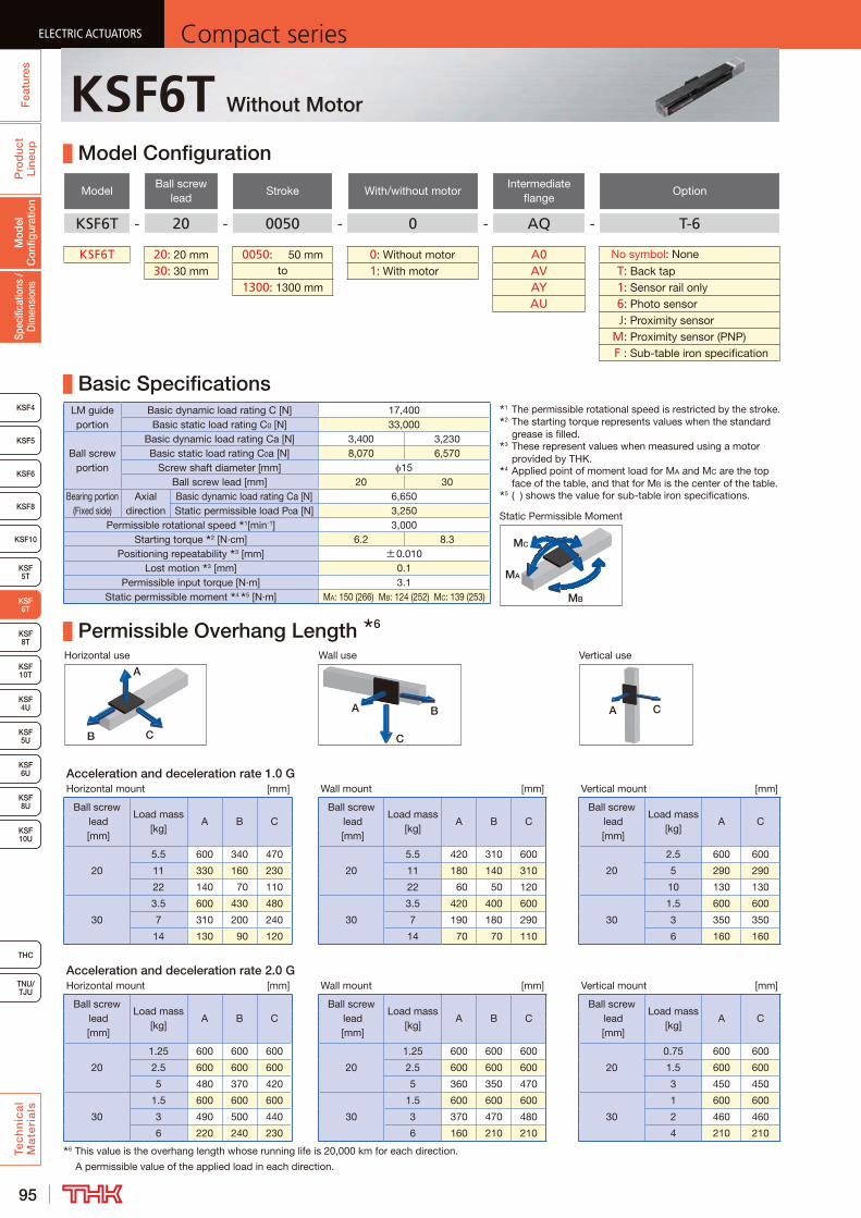
95
ELECTRIC ACTUATORS Compact seriesP
rod
uct
Line
upTe
ch
nic
al
Ma
teri
als
KSF8
KSF4
KSF 10T
KSF10
KSF 5T
KSF 8T
KSF 10U
KSF 4U
KSF 5U
KSF 6U
KSF 8U
TNU/TJU
THC
Spec
ifica
tions
/ D
imen
sion
sM
odel
C
onfig
urat
ion
Fea
ture
sELECTRIC ACTUATORS Compact series
KSF5
KSF6
ELECTRIC ACTUATORS Compact series
KSF 6T
ELECTRIC ACTUATORS Compact series
KSF6T Without Motor
Model Configuration
ModelBall screw
leadStroke With/without motor
Intermediate flange
Option
KSF6T - 20 - 0050 - 0 - AQ - T-6
KSF6T 20: 20 mm 0050: 50 mm 0: Without motor A0 No symbol: None
30: 30 mm to 1: With motor AV T : Back tap1300: 1300 mm AY 1 : Sensor rail only
AU 6 : Photo sensor J : Proximity sensor M : Proximity sensor (PNP) F : Sub-table iron specification
Basic SpecificationsLM guide portion
Basic dynamic load rating C [N] 17,400Basic static load rating C0 [N] 33,000
Ball screw portion
Basic dynamic load rating Ca [N] 3,400 3,230Basic static load rating C0a [N] 8,070 6,570
Screw shaft diameter [mm] 15Ball screw lead [mm] 20 30
Bearing portion (Fixed side)
Axial direction
Basic dynamic load rating Ca [N] 6,650Static permissible load P0a [N] 3,250
Permissible rotational speed 1[min-1] 3,000Starting torque 2 [N·cm] 6.2 8.3
Positioning repeatability 3 [mm] ±0.010Lost motion 3 [mm] 0.1
Permissible input torque [N·m] 3.1Static permissible moment 4 5 [N·m] MA: 150 (266) MB: 124 (252) MC: 139 (253)
Permissible Overhang Length 6
Horizontal use Wall use Vertical use
CB
A
A B
C
A C
Acceleration and deceleration rate 1.0 GHorizontal mount [mm] Wall mount [mm] Vertical mount [mm]
Ball screw lead [mm]
Load mass [kg]
A B CBall screw
lead [mm]
Load mass [kg]
A B CBall screw
lead [mm]
Load mass [kg]
A C
20
5.5 600 340 470
20
5.5 420 310 600
20
2.5 600 600
11 330 160 230 11 180 140 310 5 290 290
22 140 70 110 22 60 50 120 10 130 130
30
3.5 600 430 480
30
3.5 420 400 600
30
1.5 600 600
7 310 200 240 7 190 180 290 3 350 350
14 130 90 120 14 70 70 110 6 160 160
Acceleration and deceleration rate 2.0 GHorizontal mount [mm] Wall mount [mm] Vertical mount [mm]
Ball screw lead [mm]
Load mass [kg]
A B CBall screw
lead [mm]
Load mass [kg]
A B CBall screw
lead [mm]
Load mass [kg]
A C
20
1.25 600 600 600
20
1.25 600 600 600
20
0.75 600 600
2.5 600 600 600 2.5 600 600 600 1.5 600 600
5 480 370 420 5 360 350 470 3 450 450
30
1.5 600 600 600
30
1.5 600 600 600
30
1 600 600
3 490 500 440 3 370 470 480 2 460 460
6 220 240 230 6 160 210 210 4 210 2106 This value is the overhang length whose running life is 20,000 km for each direction.
A permissible value of the applied load in each direction.
1 The permissible rotational speed is restricted by the stroke.2 The starting torque represents values when the standard
grease is filled.3 These represent values when measured using a motor
provided by THK.4 Applied point of moment load for MA and MC are the top
face of the table, and that for MB is the center of the table.5 ( ) shows the value for sub-table iron specifications.
MB
MA
MC
Static Permissible Moment
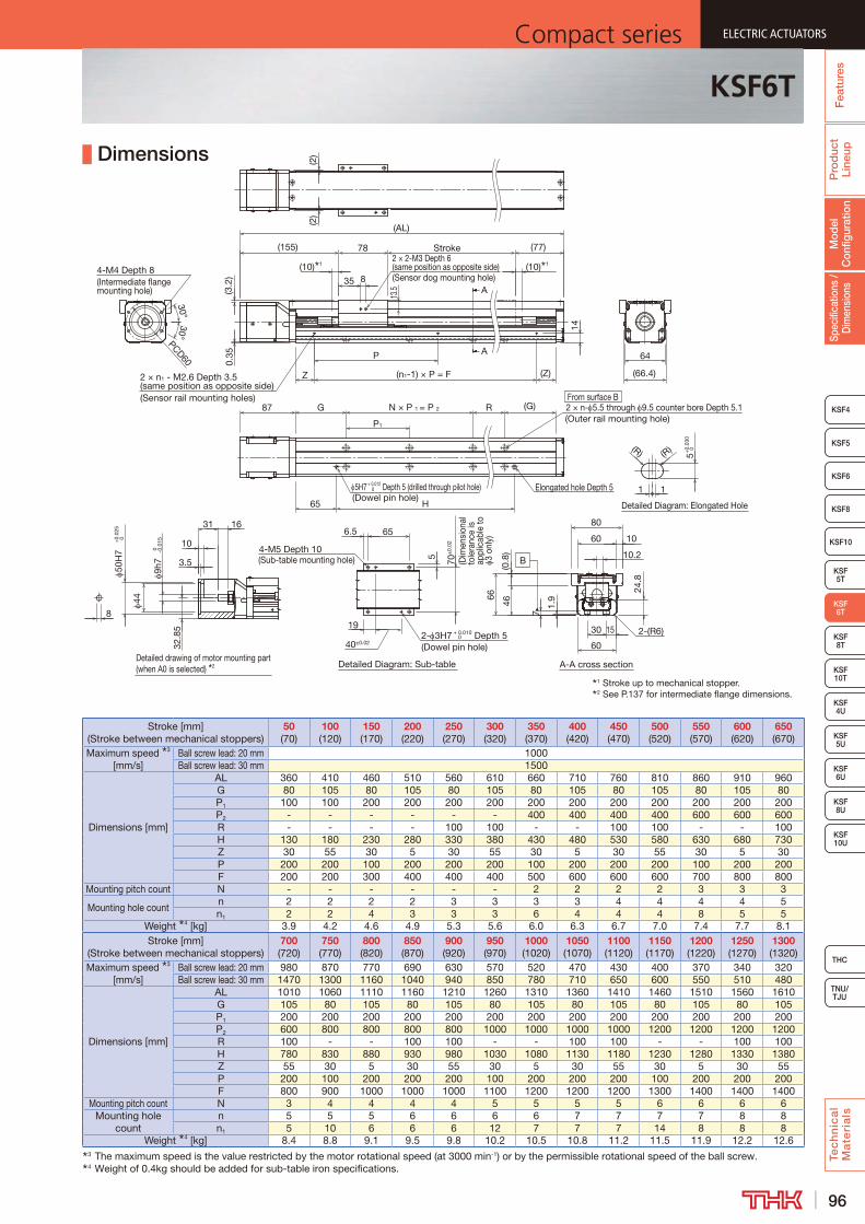
96
ELECTRIC ACTUATORSCompact series
Pro
duc
t Li
neup
Tec
hn
ica
l M
ate
ria
ls
THC
TNU/TJU
KSF8
KSF4
KSF 10T
KSF10
KSF 5T
KSF 8T
KSF 10U
KSF 4U
KSF 5U
KSF 6U
KSF 8U
Spec
ifica
tions
/ D
imen
sion
sM
odel
C
onfig
urat
ion
Fea
ture
s
ELECTRIC ACTUATORSCompact series
KSF5
KSF6
ELECTRIC ACTUATORSCompact series
KSF 6T
ELECTRIC ACTUATORSCompact series
KSF6T
Dimensions
Stroke [mm] (Stroke between mechanical stoppers)
50 (70)
100 (120)
150 (170)
200 (220)
250 (270)
300 (320)
350 (370)
400 (420)
450 (470)
500 (520)
550 (570)
600 (620)
650 (670)
Maximum speed 3 [mm/s]
Ball screw lead: 20 mm 1000Ball screw lead: 30 mm 1500
Dimensions [mm]
AL 360 410 460 510 560 610 660 710 760 810 860 910 960G 80 105 80 105 80 105 80 105 80 105 80 105 80P1 100 100 200 200 200 200 200 200 200 200 200 200 200P2 - - - - - - 400 400 400 400 600 600 600R - - - - 100 100 - - 100 100 - - 100H 130 180 230 280 330 380 430 480 530 580 630 680 730Z 30 55 30 5 30 55 30 5 30 55 30 5 30P 200 200 100 200 200 200 100 200 200 200 100 200 200F 200 200 300 400 400 400 500 600 600 600 700 800 800
Mounting pitch count N - - - - - - 2 2 2 2 3 3 3
Mounting hole countn 2 2 2 2 3 3 3 3 4 4 4 4 5n1 2 2 4 3 3 3 6 4 4 4 8 5 5
Weight 4 [kg] 3.9 4.2 4.6 4.9 5.3 5.6 6.0 6.3 6.7 7.0 7.4 7.7 8.1Stroke [mm]
(Stroke between mechanical stoppers)700 (720)
750 (770)
800 (820)
850 (870)
900 (920)
950 (970)
1000 (1020)
1050 (1070)
1100 (1120)
1150 (1170)
1200 (1220)
1250 (1270)
1300 (1320)
Maximum speed 3 [mm/s]
Ball screw lead: 20 mm 980 870 770 690 630 570 520 470 430 400 370 340 320Ball screw lead: 30 mm 1470 1300 1160 1040 940 850 780 710 650 600 550 510 480
Dimensions [mm]
AL 1010 1060 1110 1160 1210 1260 1310 1360 1410 1460 1510 1560 1610G 105 80 105 80 105 80 105 80 105 80 105 80 105P1 200 200 200 200 200 200 200 200 200 200 200 200 200P2 600 800 800 800 800 1000 1000 1000 1000 1200 1200 1200 1200R 100 - - 100 100 - - 100 100 - - 100 100H 780 830 880 930 980 1030 1080 1130 1180 1230 1280 1330 1380Z 55 30 5 30 55 30 5 30 55 30 5 30 55P 200 100 200 200 200 100 200 200 200 100 200 200 200F 800 900 1000 1000 1000 1100 1200 1200 1200 1300 1400 1400 1400
Mounting pitch count N 3 4 4 4 4 5 5 5 5 6 6 6 6Mounting hole
countn 5 5 5 6 6 6 6 7 7 7 7 8 8n1 5 10 6 6 6 12 7 7 7 14 8 8 8
Weight 4 [kg] 8.4 8.8 9.1 9.5 9.8 10.2 10.5 10.8 11.2 11.5 11.9 12.2 12.63 The maximum speed is the value restricted by the motor rotational speed (at 3000 min-1) or by the permissible rotational speed of the ball screw.4 Weight of 0.4kg should be added for sub-table iron specifications.
Elongated hole Depth 5
Detailed Diagram: Sub-table
A
A
Detailed Diagram: Elongated Hole
1 Stroke up to mechanical stopper.2 See P.137 for intermediate flange dimensions.
B
(2)
(2)
10
3.5
32.8
5
44
9h7
0 -0.0
15
31
50H
7+
0.02
5 0
16
P1
G
H65
87
5H7 + 0.012 Depth 5 (drilled through pilot hole) 0
(Dowel pin hole)
(G)RN × P 1 = P 2 2 × n- 5.5 through 9.5 counter bore Depth 5.1(Outer rail mounting hole)
(n1-1) × P = F
14
(Z)Z2 × n1 - M2.6 Depth 3.5 (same position as opposite side)(Sensor rail mounting holes)
P
78
(10) 1 (10) 1
Stroke (77)(155)
(AL)
PCD6030°
30°
4-M4 Depth 8(Intermediate flange mounting hole)
1 1
5+0.
030
0(R)(R)
5
19
6.5
4-M5 Depth 10(Sub-table mounting hole)
40±0.02
65
70±
0.02
(Dim
ensi
onal
to
lera
nce
is
appl
icab
le to
3
only
)
2- 3H7 + 0.010 Depth 5 0
(Dowel pin hole)
35
2 × 2-M3 Depth 6 (same position as opposite side)(Sensor dog mounting hole)8
0.35 64
(66.4)
8
2-(R6)
66
60
30 15
60
80
46
7
1.9
24.8
10.2
10
(0.8
)
(3.2
)
Detailed drawing of motor mounting part (when A0 is selected) 2
From surface B
A-A cross section
13.5

97
ELECTRIC ACTUATORS Compact seriesP
rod
uct
Line
upTe
ch
nic
al
Ma
teri
als
KSF8
KSF4
KSF 10T
KSF10
KSF 5T
KSF 8T
KSF 10U
KSF 4U
KSF 5U
KSF 6U
KSF 8U
TNU/TJU
THC
Spec
ifica
tions
/ D
imen
sion
sM
odel
C
onfig
urat
ion
Fea
ture
sELECTRIC ACTUATORS Compact series
KSF5
KSF6
ELECTRIC ACTUATORS Compact series
KSF 6T
ELECTRIC ACTUATORS Compact series
KSF6RT Without Motor
Model Configuration
ModelBall screw
leadStroke
With/without motor
Motor mounting plate
Motor shaft diameter
Motor shaft fixing method
Option
KSF6RT - 20 - 0050 - 0 - WV - 14 K - MR-T
KSF6RT 20: 20 mm 0050: 50 mm 0: Without motor WV 11: 11 mm D:D-cut MR : Motor right wrap30: 30 mm to 1: With motor WY 14: 14 mm K:Key ML : Motor left wrap
1300: 1300 mm M:Friction tightening MD : Motor down wrap T : Back tap 1 : Sensor rail only 6 : Photo sensor J : Proximity sensor M : Proximity sensor (PNP) F : Sub-table iron specification
Basic SpecificationsLM guide portion
Basic dynamic load rating C [N] 17,400Basic static load rating C0 [N] 33,000
Ball screw portion
Basic dynamic load rating Ca [N] 3,400 3,230Basic static load rating C0a [N] 8,070 6,570
Screw shaft diameter [mm] 15Ball screw lead [mm] 20 30
Bearing portion (Fixed side)
Axial direction
Basic dynamic load rating Ca [N] 6,650Static permissible load P0a [N] 3,250
Permissible rotational speed 1[min-1] 3,000Starting torque 2 [N·cm] 6.2 8.3
Positioning repeatability 3 [mm] ±0.010Lost motion 3 [mm] 0.1
Permissible input torque [N·m] 2.2Static permissible moment 4 5 [N·m] MA: 150 (266) MB: 124 (252) MC: 139 (253)
Permissible Overhang Length 6
Horizontal use Wall use Vertical use
CB
A
A B
C
A C
Acceleration and deceleration rate 1.0 GHorizontal mount [mm] Wall mount [mm] Vertical mount [mm]
Ball screw lead [mm]
Load mass [kg]
A B CBall screw
lead [mm]
Load mass [kg]
A B CBall screw
lead [mm]
Load mass [kg]
A C
20
4.75 600 390 540
20
4.75 490 370 600
20
2.25 600 600
9.5 390 190 270 9.5 220 160 370 4.5 330 330
19 170 90 130 19 80 60 150 9 150 150
30
2.75 600 550 600
30
2.75 550 520 600
30
1.25 600 600
5.5 410 270 310 5.5 250 240 390 2.5 430 430
11 180 120 150 11 100 100 160 5 200 200
Acceleration and deceleration rate 2.0 GHorizontal mount [mm] Wall mount [mm] Vertical mount [mm]
Ball screw lead [mm]
Load mass [kg]
A B CBall screw
lead [mm]
Load mass [kg]
A B CBall screw
lead [mm]
Load mass [kg]
A C
20
1 600 600 600
20
1 600 600 600
20
0.625 600 600
2 600 600 600 2 600 600 600 1.25 600 600
4 600 470 520 4 460 440 600 2.5 550 550
30
1 600 600 600
30
1 600 600 600
30
0.625 600 600
2 600 600 600 2 580 600 600 1.25 600 600
4 360 370 330 4 270 340 340 2.5 360 3606 This value is the overhang length whose running life is 20,000 km for each direction.
A permissible value of the applied load in each direction.
1 The permissible rotational speed is restricted by the stroke.2 The starting torque represents values when the standard
grease is filled.3 These represent values when measured using a motor
provided by THK.4 Applied point of moment load for MA and MC are the top
face of the table, and that for MB is the center of the table.5 ( ) shows the value for sub-table iron specifications.
MB
MA
MC
Static Permissible Moment
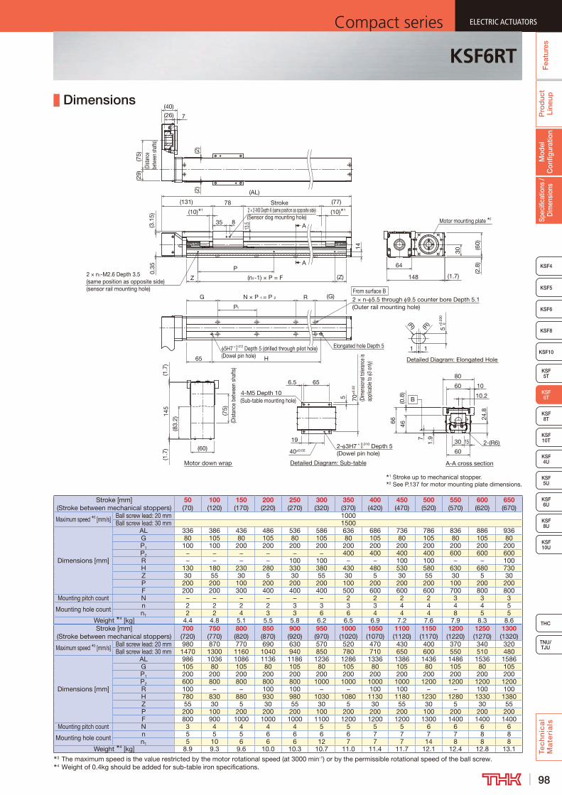
98
ELECTRIC ACTUATORSCompact series
Pro
duc
t Li
neup
Tec
hn
ica
l M
ate
ria
ls
THC
TNU/TJU
KSF8
KSF4
KSF 10T
KSF10
KSF 5T
KSF 8T
KSF 10U
KSF 4U
KSF 5U
KSF 6U
KSF 8U
Spec
ifica
tions
/ D
imen
sion
sM
odel
C
onfig
urat
ion
Fea
ture
s
ELECTRIC ACTUATORSCompact series
KSF5
KSF6
ELECTRIC ACTUATORSCompact series
KSF 6T
ELECTRIC ACTUATORSCompact series
KSF6RT
Dimensions
Stroke [mm] (Stroke between mechanical stoppers)
50 (70)
100 (120)
150 (170)
200 (220)
250 (270)
300 (320)
350 (370)
400 (420)
450 (470)
500 (520)
550 (570)
600 (620)
650 (670)
Maximum speed 3 [mm/s] Ball screw lead: 20 mm 1000Ball screw lead: 30 mm 1500
Dimensions [mm]
AL 336 386 436 486 536 586 636 686 736 786 836 886 936G 80 105 80 105 80 105 80 105 80 105 80 105 80P1 100 100 200 200 200 200 200 200 200 200 200 200 200P2 − − − − − − 400 400 400 400 600 600 600R − − − − 100 100 − − 100 100 − − 100H 130 180 230 280 330 380 430 480 530 580 630 680 730Z 30 55 30 5 30 55 30 5 30 55 30 5 30P 200 200 100 200 200 200 100 200 200 200 100 200 200F 200 200 300 400 400 400 500 600 600 600 700 800 800
Mounting pitch count N − − − − − − 2 2 2 2 3 3 3
Mounting hole count n 2 2 2 2 3 3 3 3 4 4 4 4 5n1 2 2 4 3 3 6 6 4 4 4 8 5 5
Weight 4 [kg] 4.4 4.8 5.1 5.5 5.8 6.2 6.5 6.9 7.2 7.6 7.9 8.3 8.6Stroke [mm]
(Stroke between mechanical stoppers)700 (720)
750 (770)
800 (820)
850 (870)
900 (920)
950 (970)
1000 (1020)
1050 (1070)
1100 (1120)
1150 (1170)
1200 (1220)
1250 (1270)
1300 (1320)
Maximum speed 3 [mm/s] Ball screw lead: 20 mm 980 870 770 690 630 570 520 470 430 400 370 340 320Ball screw lead: 30 mm 1470 1300 1160 1040 940 850 780 710 650 600 550 510 480
Dimensions [mm]
AL 986 1036 1086 1136 1186 1236 1286 1336 1386 1436 1486 1536 1586G 105 80 105 80 105 80 105 80 105 80 105 80 105P1 200 200 200 200 200 200 200 200 200 200 200 200 200P2 600 800 800 800 800 1000 1000 1000 1000 1200 1200 1200 1200R 100 − − 100 100 − − 100 100 − − 100 100H 780 830 880 930 980 1030 1080 1130 1180 1230 1280 1330 1380Z 55 30 5 30 55 30 5 30 55 30 5 30 55P 200 100 200 200 200 100 200 200 200 100 200 200 200F 800 900 1000 1000 1000 1100 1200 1200 1200 1300 1400 1400 1400
Mounting pitch count N 3 4 4 4 4 5 5 5 5 6 6 6 6
Mounting hole count n 5 5 5 6 6 6 6 7 7 7 7 8 8n1 5 10 6 6 6 12 7 7 7 14 8 8 8
Weight 4 [kg] 8.9 9.3 9.6 10.0 10.3 10.7 11.0 11.4 11.7 12.1 12.4 12.8 13.13 The maximum speed is the value restricted by the motor rotational speed (at 3000 min-1) or by the permissible rotational speed of the ball screw.4 Weight of 0.4kg should be added for sub-table iron specifications.
2 × n- 5.5 through 9.5 counter bore Depth 5.1
A-A cross sectionDetailed Diagram: Sub-table
5H7 + 0.012 Depth 5 (drilled through pilot hole)(Dowel pin hole)
13.5
A
A
Motor down wrap
Detailed Diagram: Elongated Hole
1 Stroke up to mechanical stopper.2 See P.137 for motor mounting plate dimensions.
B
5
1
(R)
1
N × P 1 = P 2
0.35
(n1-1) × P = F
(AL)
2 × n1-M2.6 Depth 3.5 (same position as opposite side) (sensor rail mounting hole)
(10) 1 (10) 1
Z
P
(77)Stroke(131)
(Z)
78
14
8
RFrom surface B
(Outer rail mounting hole)
G
H65
P
Elongated hole Depth 5
(75)
(Dist
ance
bet
wee
n sh
afts
)
(60)
145
(83.
2)
(1.7
)(1
.7)
(G)
(R)
2 × 2-M3 Depth 6 (same position as opposite side)(Sensor dog mounting hole)
30
148
(60)
64
(1.7)
(2.8
)
(2)
(2)
(75)
(Dist
ance
be
twee
n sha
fts)
(29)
(40)
7(26)
5
19
6.5
4-M5 Depth 10(Sub-table mounting hole)
40±0.02
65
70±
0.02
(Dim
ensio
nal to
leran
ce is
ap
plica
ble to
3 o
nly)
2- 3H7 + 0.010 Depth 5(Dowel pin hole)
35
(3.1
5)
Motor mounting plate 2
2-(R6)
66
60
30 15
60
80
46
7
1.9
24.8
10.2
10
(0.8
)
+0.
030
0
0
1
0

99
ELECTRIC ACTUATORS Compact seriesP
rod
uct
Line
upTe
ch
nic
al
Ma
teri
als
KSF8
KSF4
KSF 10T
KSF10
KSF 5T
KSF 6T
KSF 10U
KSF 5U
KSF 6U
KSF 8U
TNU/TJU
THC
Spec
ifica
tions
/ D
imen
sion
sM
odel
C
onfig
urat
ion
Fea
ture
sELECTRIC ACTUATORS Compact series
KSF5
KSF6
ELECTRIC ACTUATORS Compact series
KSF 8T
KSF 4U
ELECTRIC ACTUATORS Compact series
KSF8T Without Motor
Model Configuration
ModelBall screw
leadStroke With/without motor
Intermediate flange
Option
KSF8T - 20 - 0800 - 0 - AV - T-6
KSF8T 20: 20 mm 0100: 100 mm 0: Without motor A0 No symbol: None
40: 40 mm to 1: With motor AV T : Back tap1500: 1500 mm AY 1 : Sensor rail only
AU 6 : Photo sensor J : Proximity sensor M : Proximity sensor (PNP) F : Sub-table iron specification
Basic SpecificationsLM guide portion
Basic dynamic load rating C [N] 32,400Basic static load rating C0 [N] 63,500
Ball screw portion
Basic dynamic load rating Ca [N] 4,030 3,750Basic static load rating C0a [N] 10,540 8,870
Screw shaft diameter [mm] 20Ball screw lead [mm] 20 40
Bearing portion (Fixed side)
Axial direction
Basic dynamic load rating Ca [N] 7,600Static permissible load P0a [N] 4,000
Permissible rotational speed 1[min-1] 3,000Starting torque 2 [N·cm] 12
Positioning repeatability 3 [mm] ±0.010Lost motion 3 [mm] 0.1
Permissible input torque [N·m] 7.1Static permissible moment 4 5 [N·m] MA: 324 (730) MB: 253 (425) MC: 265 (503)
Permissible Overhang Length 6
Horizontal use Wall use Vertical use
CB
A
A B
C
A C
Acceleration and deceleration rate 1.0 GHorizontal mount [mm] Wall mount [mm] Vertical mount [mm]
Ball screw lead [mm]
Load mass [kg]
A B CBall screw
lead [mm]
Load mass [kg]
A B CBall screw
lead [mm]
Load mass [kg]
A C
20
10.75 800 500 640
20
10.75 590 470 800
20
5 800 800
21.5 500 240 320 21.5 260 210 470 10 430 430
43 220 110 150 43 100 80 190 20 200 200
40
4 800 800 800
40
4 800 800 800
40
2 800 800
8 690 530 480 8 420 500 660 4 690 690
16 320 250 240 16 180 220 290 8 320 320
Acceleration and deceleration rate 2.0 GHorizontal mount [mm] Wall mount [mm] Vertical mount [mm]
Ball screw lead [mm]
Load mass [kg]
A B CBall screw
lead [mm]
Load mass [kg]
A B CBall screw
lead [mm]
Load mass [kg]
A C
20
1.5 800 800 800
20
1.5 800 800 800
20
0.75 800 800
3 800 800 800 3 800 800 800 1.5 800 800
6 800 800 800 6 800 800 800 3 800 800
40
1.75 800 800 800
40
1.75 800 800 800
40
1.25 800 800
3.5 800 800 800 3.5 780 800 800 2.5 800 800
7 490 610 440 7 370 570 470 5 440 4406 This value is the overhang length whose running life is 20,000 km for each direction.
A permissible value of the applied load in each direction.
1 The permissible rotational speed is restricted by the stroke.2 The starting torque represents values when the standard
grease is filled.3 These represent values when measured using a motor
provided by THK.4 Applied point of moment load for MA and MC are the top
face of the table, and that for MB is the center of the table.5 ( ) shows the value for sub-table iron specifications.
MB
MA
MC
Static Permissible Moment

100
ELECTRIC ACTUATORSCompact series
Pro
duc
t Li
neup
Tec
hn
ica
l M
ate
ria
ls
THC
TNU/TJU
KSF8
KSF4
KSF 10T
KSF10
KSF 5T
KSF 6T
KSF 10U
KSF 5U
KSF 6U
KSF 8U
Spec
ifica
tions
/ D
imen
sion
sM
odel
C
onfig
urat
ion
Fea
ture
s
ELECTRIC ACTUATORSCompact series
KSF5
KSF6
ELECTRIC ACTUATORSCompact series
KSF 8T
KSF 4U
ELECTRIC ACTUATORSCompact series
KSF8T
Dimensions
Stroke [mm] (Stroke between mechanical stoppers)
100 (120)
200 (220)
300 (320)
400 (420)
500 (520)
600 (620)
700 (720)
800 (820)
900 (920)
1000 (1020)
1100 (1120)
1200 (1220)
1300 (1320)
1400 (1420)
1500 (1520)
Maximum speed 3 [mm/s]
Ball screw lead: 20 mm 1000 970 790 660 550 470 410 360 320Ball screw lead: 40 mm 2000 1940 1580 1320 1110 950 830 720 640
Dimensions 4 [mm]
AL 478 578 678 778 878 978 1078 1178 1278 1378 1478 1578 1678 1778 1887G 85 135 85 135 85 135 85 135 85 135 85 135 85 135 85H 300 400 500 600 700 800 900 1000 1100 1200 1300 1400 1500 1600 1700Z 85 35 85 35 85 35 85 35 85 35 85 35 85 35 85F 200 400 400 600 600 800 800 1000 1000 1200 1200 1400 1400 1600 1600
Mounting pitch count N 1 1 2 2 3 3 4 4 5 5 6 6 7 7 8Mounting hole
countn 2 2 3 3 4 4 5 5 6 6 7 7 8 8 9n1 2 3 3 4 4 5 5 6 6 7 7 8 8 9 9
Weight 4 [kg] 8.4 9.7 10.9 12.2 13.4 14.7 15.9 17.2 18.4 19.7 20.9 22.2 23.5 24.7 26.03 The maximum speed is the value restricted by the motor rotational speed (at 3000 min-1) or by the permissible rotational speed of the ball screw.4 Weight of 1.1kg should be added for sub-table iron specifications.
From surface B
5H7 + 0.012 Depth 5 (drilled through pilot hole)
Detailed Diagram: Elongated Hole
Detailed Diagram: Sub-tableDetailed drawing of motor mounting part (when A0 is selected) 2
1 Stroke up to mechanical stopper.2 See P.138 for intermediate flange dimensions.
A
A
A-A cross section
B
(2)
17
37
50H
7+
0.02
5 0
(2)
(R) (R) 5
+0.
030
0
11
10
12h7
0 -0.0
18
31
44
3.5
14
11
0
(Dowel pin hole)
G2 × n- 6.6 through 11 counter bore Depth 6.3(Outer rail mounting hole)
N × 200
H
Elongated hole Depth 5
93
35
200
(G)
Stroke (90)(168) 120
(10) 1 (10) 1
Z (Z)(n1-1) × P = F
P
19
2 × n1 - M2.6 Depth 3.5 (same position as opposite side)(Sensor rail mounting holes)
(AL)
4-M4 Depth 8(Intermediate flange mounting hole)
30°
PCD60
30°
70±0.02
4-M6 Depth 12(Sub-table mounting hole)
25
4-M4 Depth 8 (From the back surface)(Sensor dog mounting hole) 2- 5H7 + 0.012 Depth 10 0
(Dowel pin hole)
100
50
92±
0.02
(Dim
ensi
onal
to
lera
nce
is
app
licab
le t
o 5
only
)
120
10
20
6
1
84
(86.4)
31.2
48
104
46
(0.8
)
80
80
17
12
10 3.7
2-(R6)
80
16
(12.
7)
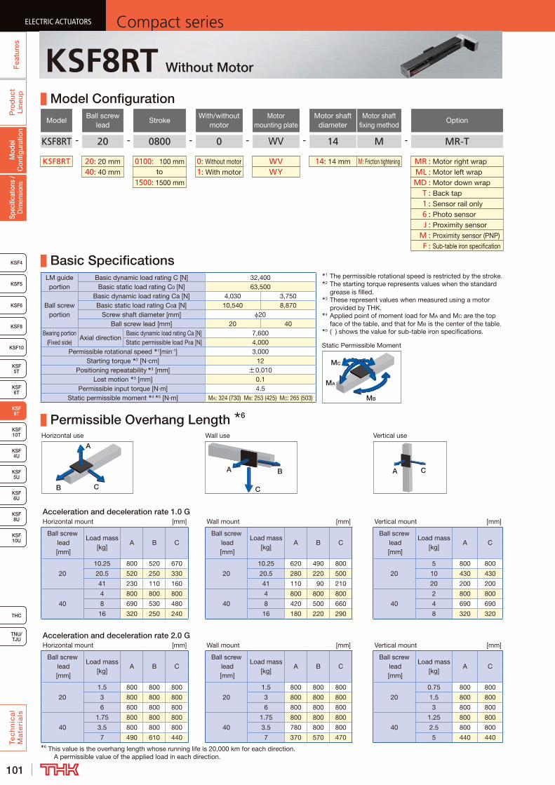
101
ELECTRIC ACTUATORS Compact seriesP
rod
uct
Line
upTe
ch
nic
al
Ma
teri
als
KSF8
KSF4
KSF 10T
KSF10
KSF 5T
KSF 6T
KSF 10U
KSF 5U
KSF 6U
KSF 8U
TNU/TJU
THC
Spec
ifica
tions
/ D
imen
sion
sM
odel
C
onfig
urat
ion
Fea
ture
sELECTRIC ACTUATORS Compact series
KSF5
KSF6
ELECTRIC ACTUATORS Compact series
KSF 8T
KSF 4U
ELECTRIC ACTUATORS Compact series
KSF8RT Without Motor
Model Configuration
ModelBall screw
leadStroke
With/without motor
Motor mounting plate
Motor shaft diameter
Motor shaft fixing method
Option
KSF8RT - 20 - 0800 - 0 - WV - 14 M - MR-T
KSF8RT 20: 20 mm 0100: 100 mm 0: Without motor WV 14: 14 mm M: Friction tightening MR : Motor right wrap40: 40 mm to 1: With motor WY ML : Motor left wrap
1500: 1500 mm MD : Motor down wrap T : Back tap 1 : Sensor rail only 6 : Photo sensor J : Proximity sensor M : Proximity sensor (PNP) F : Sub-table iron specification
Basic SpecificationsLM guide portion
Basic dynamic load rating C [N] 32,400Basic static load rating C0 [N] 63,500
Ball screw portion
Basic dynamic load rating Ca [N] 4,030 3,750Basic static load rating C0a [N] 10,540 8,870
Screw shaft diameter [mm] 20Ball screw lead [mm] 20 40
Bearing portion (Fixed side)
Axial directionBasic dynamic load rating Ca [N] 7,600Static permissible load P0a [N] 4,000
Permissible rotational speed 1[min-1] 3,000Starting torque 2 [N·cm] 12
Positioning repeatability 3 [mm] ±0.010Lost motion 3 [mm] 0.1
Permissible input torque [N·m] 4.5Static permissible moment 4 5 [N·m] MA: 324 (730) MB: 253 (425) MC: 265 (503)
Permissible Overhang Length 6
Horizontal use Wall use Vertical use
CB
A
A B
C
A C
Acceleration and deceleration rate 1.0 GHorizontal mount [mm] Wall mount [mm] Vertical mount [mm]
Ball screw lead [mm]
Load mass [kg]
A B CBall screw
lead [mm]
Load mass [kg]
A B CBall screw
lead [mm]
Load mass [kg]
A C
20
10.25 800 520 670
20
10.25 620 490 800
20
5 800 800
20.5 520 250 330 20.5 280 220 500 10 430 430
41 230 110 160 41 110 90 210 20 200 200
40
4 800 800 800
40
4 800 800 800
40
2 800 800
8 690 530 480 8 420 500 660 4 690 690
16 320 250 240 16 180 220 290 8 320 320
Acceleration and deceleration rate 2.0 GHorizontal mount [mm] Wall mount [mm] Vertical mount [mm]
Ball screw lead [mm]
Load mass [kg]
A B CBall screw
lead [mm]
Load mass [kg]
A B CBall screw
lead [mm]
Load mass [kg]
A C
20
1.5 800 800 800
20
1.5 800 800 800
20
0.75 800 800
3 800 800 800 3 800 800 800 1.5 800 800
6 800 800 800 6 800 800 800 3 800 800
40
1.75 800 800 800
40
1.75 800 800 800
40
1.25 800 800
3.5 800 800 800 3.5 780 800 800 2.5 800 800
7 490 610 440 7 370 570 470 5 440 4406 This value is the overhang length whose running life is 20,000 km for each direction.
A permissible value of the applied load in each direction.
1 The permissible rotational speed is restricted by the stroke.2 The starting torque represents values when the standard
grease is filled.3 These represent values when measured using a motor
provided by THK.4 Applied point of moment load for MA and MC are the top
face of the table, and that for MB is the center of the table.5 ( ) shows the value for sub-table iron specifications.
MB
MA
MC
Static Permissible Moment
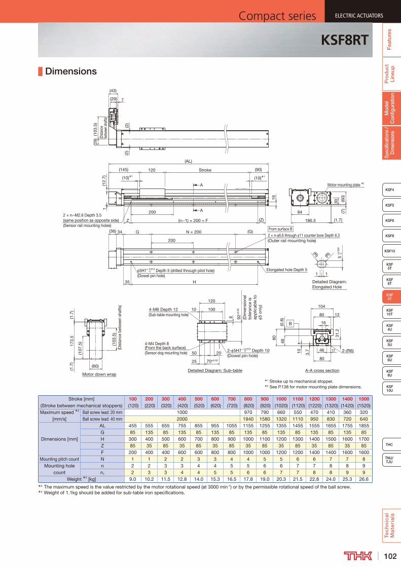
102
ELECTRIC ACTUATORSCompact series
Pro
duc
t Li
neup
Tec
hn
ica
l M
ate
ria
ls
THC
TNU/TJU
KSF8
KSF4
KSF 10T
KSF10
KSF 5T
KSF 6T
KSF 10U
KSF 5U
KSF 6U
KSF 8U
Spec
ifica
tions
/ D
imen
sion
sM
odel
C
onfig
urat
ion
Fea
ture
s
ELECTRIC ACTUATORSCompact series
KSF5
KSF6
ELECTRIC ACTUATORSCompact series
KSF 8T
KSF 4U
ELECTRIC ACTUATORSCompact series
KSF8RT
Dimensions
Stroke [mm] (Stroke between mechanical stoppers)
100 (120)
200 (220)
300 (320)
400 (420)
500 (520)
600 (620)
700 (720)
800 (820)
900 (920)
1000 (1020)
1100 (1120)
1200 (1220)
1300 (1320)
1400 (1420)
1500 (1520)
Maximum speed 3 [mm/s]
Ball screw lead: 20 mm 1000 970 790 660 550 470 410 360 320Ball screw lead: 40 mm 2000 1940 1580 1320 1110 950 830 720 640
Dimensions [mm]
AL 455 555 655 755 855 955 1055 1155 1255 1355 1455 1555 1655 1755 1855G 85 135 85 135 85 135 85 135 85 135 85 135 85 135 85H 300 400 500 600 700 800 900 1000 1100 1200 1300 1400 1500 1600 1700Z 85 35 85 35 85 35 85 35 85 35 85 35 85 35 85F 200 400 400 600 600 800 800 1000 1000 1200 1200 1400 1400 1600 1600
Mounting pitch count N 1 1 2 2 3 3 4 4 5 5 6 6 7 7 8Mounting hole
countn 2 2 3 3 4 4 5 5 6 6 7 7 8 8 9n1 2 3 3 4 4 5 5 6 6 7 7 8 8 9 9
Weight 4 [kg] 9.0 10.2 11.5 12.8 14.0 15.3 16.5 17.8 19.0 20.3 21.5 22.8 24.0 25.3 26.63 The maximum speed is the value restricted by the motor rotational speed (at 3000 min-1) or by the permissible rotational speed of the ball screw.4 Weight of 1.1kg should be added for sub-table iron specifications.
1 Stroke up to mechanical stopper.2 See P.138 for motor mounting plate dimensions.
2 × n- 6.6 through 11 counter bore Depth 6.3
Motor down wrap
Detailed Diagram: Elongated Hole
Detailed Diagram: Sub-table
A
A
A-A cross section
B
G
5H7 + 0.012 Depth 5 (drilled through pilot hole)(Dowel pin hole)
0 Elongated hole Depth 5
N × 200
H35
(G)
200
173.
5
(107
.5)
(1.7
)
(103
.5)
(Dis
tanc
e be
twee
n sh
afts
)
11
(R) (R)
5+
0.03
0 0
(Outer rail mounting hole)
(36) 34
(1.7
)
(AL)
(10) 1
Z
(10) 1
(90)
(Z)(n1-1) × 200 = F
2002 × n1-M2.6 Depth 3.5 (same position as opposite side)(Sensor rail mounting holes)
Stroke
1
19
120(145)
84
(60)
30
(7)
(1.7)186.5
(29)
(103
.5)
(Dist
ance
be
twee
n sh
afts)
7(29)
(43)
(2)
(2)
Motor mounting plate 2
70±0.02
4-M6 Depth 12(Sub-table mounting hole)
25
4-M4 Depth 8 (From the back surface)(Sensor dog mounting hole) 2- 5H7 + 0.012 Depth 10
(Dowel pin hole) 0
100
50
92±
0.02
(Dim
ensi
onal
to
lera
nce
is
app
licab
le t
o 5
only
)
120
10
20
6
(60)
(12.
7)
31.2
48
104
46
(0.8
)
80
80
17
12
10 3.7 2-(R6)
80
16
From surface B
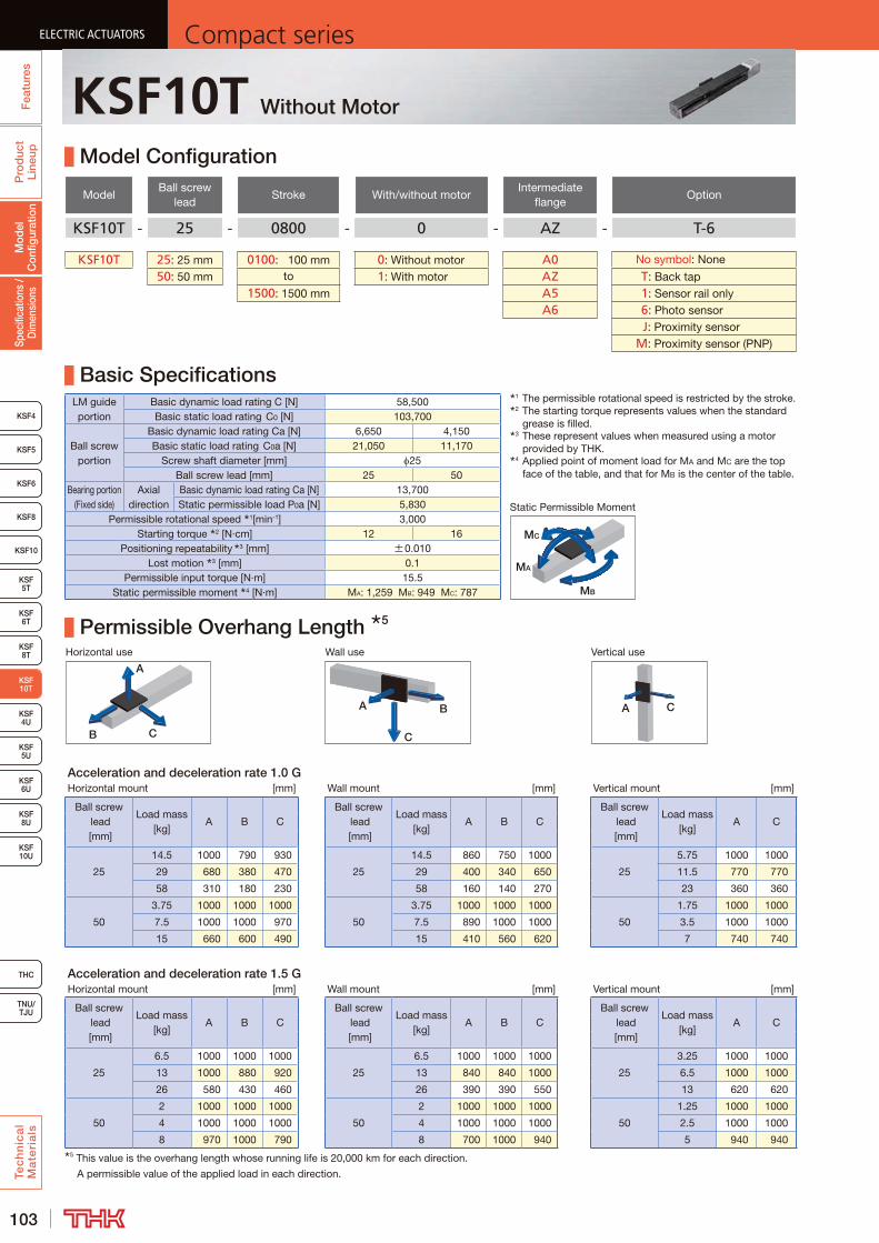
103
ELECTRIC ACTUATORS Compact seriesP
rod
uct
Line
upTe
ch
nic
al
Ma
teri
als
KSF8
KSF4
KSF10
KSF 5T
KSF 6T
KSF 8T
KSF 10U
KSF 4U
KSF 5U
KSF 6U
TNU/TJU
THC
Spec
ifica
tions
/ D
imen
sion
sM
odel
C
onfig
urat
ion
Fea
ture
sELECTRIC ACTUATORS Compact series
KSF5
KSF6
ELECTRIC ACTUATORS Compact series
KSF 10T
KSF 8U
ELECTRIC ACTUATORS Compact series
KSF10T Without Motor
Model Configuration
ModelBall screw
leadStroke With/without motor
Intermediate flange
Option
KSF10T - 25 - 0800 - 0 - AZ - T-6
KSF10T 25: 25 mm 0100: 100 mm 0: Without motor A0 No symbol: None
50: 50 mm to 1: With motor AZ T : Back tap1500: 1500 mm A5 1 : Sensor rail only
A6 6 : Photo sensor J : Proximity sensor M : Proximity sensor (PNP)
Basic SpecificationsLM guide portion
Basic dynamic load rating C [N] 58,500Basic static load rating C0 [N] 103,700
Ball screw portion
Basic dynamic load rating Ca [N] 6,650 4,150Basic static load rating C0a [N] 21,050 11,170
Screw shaft diameter [mm] 25Ball screw lead [mm] 25 50
Bearing portion (Fixed side)
Axial direction
Basic dynamic load rating Ca [N] 13,700Static permissible load P0a [N] 5,830
Permissible rotational speed 1[min-1] 3,000Starting torque 2 [N·cm] 12 16
Positioning repeatability 3 [mm] ±0.010Lost motion 3 [mm] 0.1
Permissible input torque [N·m] 15.5Static permissible moment 4 [N·m] MA: 1,259 MB: 949 MC: 787
Permissible Overhang Length 5
Horizontal use Wall use Vertical use
CB
A
A B
C
A C
Acceleration and deceleration rate 1.0 GHorizontal mount [mm] Wall mount [mm] Vertical mount [mm]
Ball screw lead [mm]
Load mass [kg]
A B CBall screw
lead [mm]
Load mass [kg]
A B CBall screw
lead [mm]
Load mass [kg]
A C
25
14.5 1000 790 930
25
14.5 860 750 1000
25
5.75 1000 1000
29 680 380 470 29 400 340 650 11.5 770 770
58 310 180 230 58 160 140 270 23 360 360
50
3.75 1000 1000 1000
50
3.75 1000 1000 1000
50
1.75 1000 1000
7.5 1000 1000 970 7.5 890 1000 1000 3.5 1000 1000
15 660 600 490 15 410 560 620 7 740 740
Acceleration and deceleration rate 1.5 GHorizontal mount [mm] Wall mount [mm] Vertical mount [mm]
Ball screw lead [mm]
Load mass [kg]
A B CBall screw
lead [mm]
Load mass [kg]
A B CBall screw
lead [mm]
Load mass [kg]
A C
25
6.5 1000 1000 1000
25
6.5 1000 1000 1000
25
3.25 1000 1000
13 1000 880 920 13 840 840 1000 6.5 1000 1000
26 580 430 460 26 390 390 550 13 620 620
50
2 1000 1000 1000
50
2 1000 1000 1000
50
1.25 1000 1000
4 1000 1000 1000 4 1000 1000 1000 2.5 1000 1000
8 970 1000 790 8 700 1000 940 5 940 9405 This value is the overhang length whose running life is 20,000 km for each direction.
A permissible value of the applied load in each direction.
1 The permissible rotational speed is restricted by the stroke.2 The starting torque represents values when the standard
grease is filled.3 These represent values when measured using a motor
provided by THK.4 Applied point of moment load for MA and MC are the top
face of the table, and that for MB is the center of the table.
MB
MA
MC
Static Permissible Moment

104
ELECTRIC ACTUATORSCompact series
Pro
duc
t Li
neup
Tec
hn
ica
l M
ate
ria
ls
THC
TNU/TJU
KSF8
KSF4
KSF10
KSF 5T
KSF 6T
KSF 8T
KSF 10U
KSF 4U
KSF 5U
KSF 6U
Spec
ifica
tions
/ D
imen
sion
sM
odel
C
onfig
urat
ion
Fea
ture
s
ELECTRIC ACTUATORSCompact series
KSF5
KSF6
ELECTRIC ACTUATORSCompact series
KSF 10T
KSF 8U
ELECTRIC ACTUATORSCompact series
KSF10T
Dimensions
Stroke [mm] (Stroke between mechanical stoppers)
100 (120)
200 (220)
300 (320)
400 (420)
500 (520)
600 (620)
700 (720)
800 (820)
900 (920)
1000 (1020)
1100 (1120)
1200 (1220)
1300 (1320)
1400 (1420)
1500 (1520)
Maximum speed 3 [mm/s]
Ball screw lead: 25 mm 1250 1050 890 760 660 580 510Ball screw lead: 50 mm 2500 2110 1790 1530 1330 1160 1030
Dimensions [mm]
AL 525 625 725 825 925 1025 1125 1225 1325 1425 1525 1625 1725 1825 1925G 120 95 70 120 95 70 120 95 70 120 95 70 120 95 70H 320 420 520 620 720 820 920 1020 1120 1220 1320 1420 1520 1620 1720Z 95 45 95 45 95 45 95 45 95 45 95 45 95 45 95F 200 400 400 600 600 800 800 1000 1000 1200 1200 1400 1400 1600 1600
Mounting pitch count N 1 2 3 3 4 5 5 6 7 7 8 9 9 10 11Mounting hole
countn 2 3 4 4 5 6 6 7 8 8 9 10 10 11 12n1 2 3 3 4 4 5 5 6 6 7 7 8 8 9 9
Weight [kg] 16.8 18.8 20.8 22.7 24.7 26.7 28.7 30.6 32.6 34.6 36.6 38.6 40.5 42.5 44.53 The maximum speed is the value restricted by the motor rotational speed (at 3000 min-1) or by the permissible rotational speed of the ball screw.
Detailed Diagram: Sub-table
Detailed Diagram: Elongated Hole
Detailed drawing of motor mounting part (when A0 is selected) 2 A-A cross section
A
A
1 Stroke up to mechanical stopper.2 See P.139 for intermediate flange dimensions.
B
(2)
H
(G)115
Elongated hole Depth 5
N × 150
(2)
From surface B
2 × n- 9 through 14 counter bore Depth 8.4(Outer rail mounting hole)
5H7 +0.012 0 Depth 5 (drilled through pilot hole)
(Dowel pin hole)1
5+
0.03
0 0
1
(R)
12
14
150
49
15
1638
(R)
G
50H
7+
0.02
5 0
15h7
0 -0.0
18
35
45°
PCD7
0
45°
4-M5 Depth 10(Intermediate flange mounting hole)
(10) 1 (10) 1
(190) Stroke (95)140
(AL)
Z (n1-1) × P = F
P
(Z)2 × n1-M2.6 Depth 3.5 (same position as opposite side)(Sensor rail mounting holes)
60
7
25
20
120
110±
0.02
(Dim
ensio
nal t
oler
ance
is
appl
icabl
e to
5
only)
4-M8 Depth 16(Sub-table mounting hole)
10
2- 5H7+0.012 0 Depth 10
(Dowel pin hole)
90±0.02
4-M4 Depth 8 (From the back surface)
(Sensor dog mounting hole)
25
100
20
50
100
41.4
(0.8
)14.595
124
63
13 4.6
0.5 104
27
(106.4)
2-(C3)
(11)
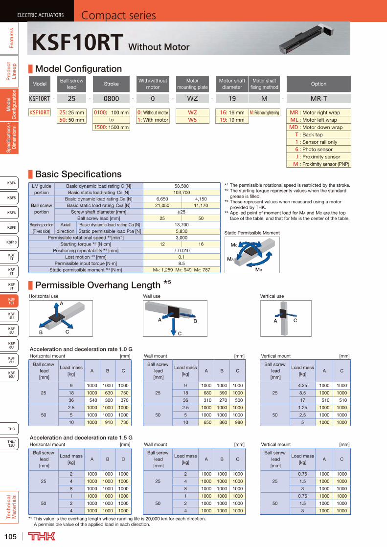
105
ELECTRIC ACTUATORS Compact seriesP
rod
uct
Line
upTe
ch
nic
al
Ma
teri
als
KSF8
KSF4
KSF10
KSF 5T
KSF 6T
KSF 8T
KSF 10U
KSF 4U
KSF 5U
KSF 6U
TNU/TJU
THC
Spec
ifica
tions
/ D
imen
sion
sM
odel
C
onfig
urat
ion
Fea
ture
sELECTRIC ACTUATORS Compact series
KSF5
KSF6
ELECTRIC ACTUATORS Compact series
KSF 10T
KSF 8U
ELECTRIC ACTUATORS Compact series
KSF10RT Without Motor
Model Configuration
ModelBall screw
leadStroke
With/without motor
Motor mounting plate
Motor shaft diameter
Motor shaft fixing method
Option
KSF10RT - 25 - 0800 - 0 - WZ - 19 M - MR-T
KSF10RT 25: 25 mm 0100: 100 mm 0: Without motor WZ 16: 16 mm M: Friction tightening MR : Motor right wrap50: 50 mm to 1: With motor W5 19: 19 mm ML : Motor left wrap
1500: 1500 mm MD : Motor down wrap T : Back tap 1 : Sensor rail only 6 : Photo sensor J : Proximity sensor M : Proximity sensor (PNP)
Basic SpecificationsLM guide portion
Basic dynamic load rating C [N] 58,500Basic static load rating C0 [N] 103,700
Ball screw portion
Basic dynamic load rating Ca [N] 6,650 4,150Basic static load rating C0a [N] 21,050 11,170
Screw shaft diameter [mm] 25Ball screw lead [mm] 25 50
Bearing portion (Fixed side)
Axial direction
Basic dynamic load rating Ca [N] 13,700Static permissible load P0a [N] 5,830
Permissible rotational speed 1[min-1] 3,000Starting torque 2 [N·cm] 12 16
Positioning repeatability 3 [mm] ±0.010Lost motion 3 [mm] 0.1
Permissible input torque [N·m] 8.5Static permissible moment 4 [N·m] MA: 1,259 MB: 949 MC: 787
Permissible Overhang Length 5
Horizontal use Wall use Vertical use
CB
A
A B
C
A C
Acceleration and deceleration rate 1.0 GHorizontal mount [mm] Wall mount [mm] Vertical mount [mm]
Ball screw lead [mm]
Load mass [kg]
A B CBall screw
lead [mm]
Load mass [kg]
A B CBall screw
lead [mm]
Load mass [kg]
A C
25
9 1000 1000 1000
25
9 1000 1000 1000
25
4.25 1000 1000
18 1000 630 750 18 680 590 1000 8.5 1000 1000
36 540 300 370 36 310 270 500 17 510 510
50
2.5 1000 1000 1000
50
2.5 1000 1000 1000
50
1.25 1000 1000
5 1000 1000 1000 5 1000 1000 1000 2.5 1000 1000
10 1000 910 730 10 650 860 980 5 1000 1000
Acceleration and deceleration rate 1.5 GHorizontal mount [mm] Wall mount [mm] Vertical mount [mm]
Ball screw lead [mm]
Load mass [kg]
A B CBall screw
lead [mm]
Load mass [kg]
A B CBall screw
lead [mm]
Load mass [kg]
A C
25
2 1000 1000 1000
25
2 1000 1000 1000
25
0.75 1000 1000
4 1000 1000 1000 4 1000 1000 1000 1.5 1000 1000
8 1000 1000 1000 8 1000 1000 1000 3 1000 1000
50
1 1000 1000 1000
50
1 1000 1000 1000
50
0.75 1000 1000
2 1000 1000 1000 2 1000 1000 1000 1.5 1000 1000
4 1000 1000 1000 4 1000 1000 1000 3 1000 10005 This value is the overhang length whose running life is 20,000 km for each direction.
A permissible value of the applied load in each direction.
1 The permissible rotational speed is restricted by the stroke.2 The starting torque represents values when the standard
grease is filled.3 These represent values when measured using a motor
provided by THK.4 Applied point of moment load for MA and MC are the top
face of the table, and that for MB is the center of the table.
MB
MA
MC
Static Permissible Moment
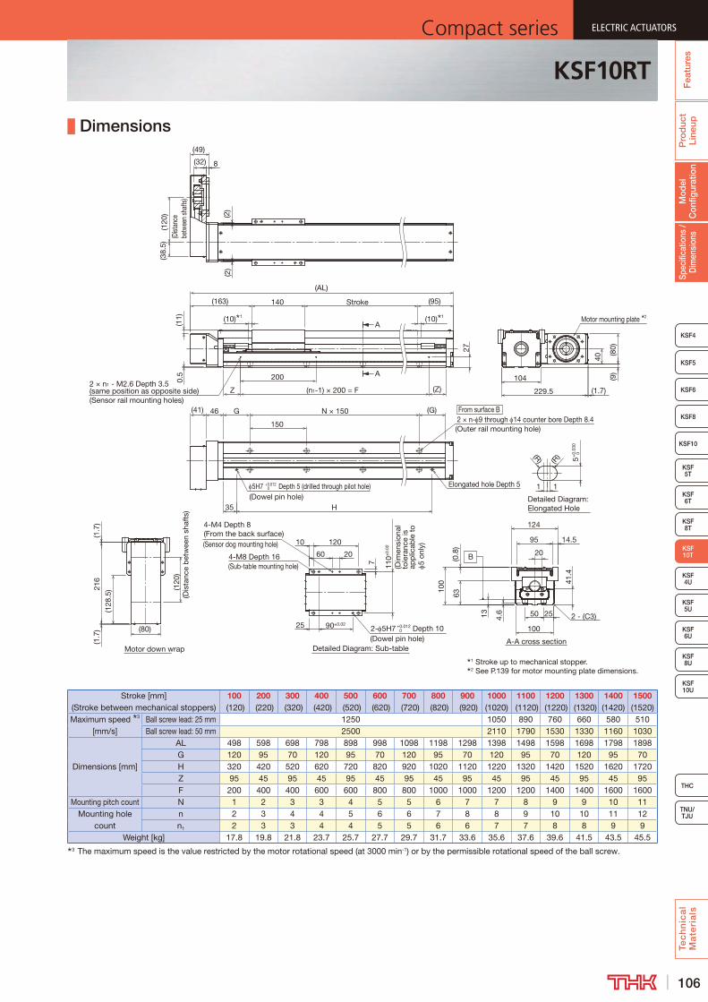
106
ELECTRIC ACTUATORSCompact series
Pro
duc
t Li
neup
Tec
hn
ica
l M
ate
ria
ls
THC
TNU/TJU
KSF8
KSF4
KSF10
KSF 5T
KSF 6T
KSF 8T
KSF 10U
KSF 4U
KSF 5U
KSF 6U
Spec
ifica
tions
/ D
imen
sion
sM
odel
C
onfig
urat
ion
Fea
ture
s
ELECTRIC ACTUATORSCompact series
KSF5
KSF6
ELECTRIC ACTUATORSCompact series
KSF 10T
KSF 8U
ELECTRIC ACTUATORSCompact series
KSF10RT
Dimensions
Stroke [mm] (Stroke between mechanical stoppers)
100 (120)
200 (220)
300 (320)
400 (420)
500 (520)
600 (620)
700 (720)
800 (820)
900 (920)
1000 (1020)
1100 (1120)
1200 (1220)
1300 (1320)
1400 (1420)
1500 (1520)
Maximum speed 3 [mm/s]
Ball screw lead: 25 mm 1250 1050 890 760 660 580 510Ball screw lead: 50 mm 2500 2110 1790 1530 1330 1160 1030
Dimensions [mm]
AL 498 598 698 798 898 998 1098 1198 1298 1398 1498 1598 1698 1798 1898G 120 95 70 120 95 70 120 95 70 120 95 70 120 95 70H 320 420 520 620 720 820 920 1020 1120 1220 1320 1420 1520 1620 1720Z 95 45 95 45 95 45 95 45 95 45 95 45 95 45 95F 200 400 400 600 600 800 800 1000 1000 1200 1200 1400 1400 1600 1600
Mounting pitch count N 1 2 3 3 4 5 5 6 7 7 8 9 9 10 11Mounting hole
countn 2 3 4 4 5 6 6 7 8 8 9 10 10 11 12n1 2 3 3 4 4 5 5 6 6 7 7 8 8 9 9
Weight [kg] 17.8 19.8 21.8 23.7 25.7 27.7 29.7 31.7 33.6 35.6 37.6 39.6 41.5 43.5 45.53 The maximum speed is the value restricted by the motor rotational speed (at 3000 min-1) or by the permissible rotational speed of the ball screw.
A-A cross section
Detailed Diagram: Elongated Hole
2 × n- 9 through 14 counter bore Depth 8.4
A
A
Motor down wrap Detailed Diagram: Sub-table1 Stroke up to mechanical stopper.2 See P.139 for motor mounting plate dimensions.
B
2 × n1 - M2.6 Depth 3.5 (same position as opposite side) (Z)Z (n1-1) × 200 = F
(AL)
200
27
(10) 1 (10) 1
Stroke
60
7
25
20
120
110±
0.02
4-M8 Depth 16(Sub-table mounting hole)
10
2- 5H7 +0.0120 Depth 10
(Dowel pin hole)
90±0.02
4-M4 Depth 8 (From the back surface)(Sensor dog mounting hole)
1
140 (95)(163)
1
5+0.
030
0
(R)(R)
(120
)(D
ista
nce
bet
wee
n sh
afts
)
(128
.5)21
6(1
.7)
(1.7
)
(80)
From surface B
(Outer rail mounting hole)
46
150
5H7 +0.012 0 Depth 5 (drilled through pilot hole)
(Dowel pin hole)
Elongated hole Depth 5
H
G (G)N × 150
35
(41)
104
229.5 (1.7)
40
(9)
(80)
(2)
(2)
8(32)
(49)
(38.
5)(1
20)
(Dist
ance
be
twee
n sh
afts
)0.
5
Motor mounting plate 2
(11)
41.4
4.6
100
100
20
(0.8
)
50 2513
14.5
63
95
124
2 - (C3)
(Sensor rail mounting holes)(D
imen
sion
al
tole
ranc
e is
ap
plic
able
to
5 on
ly)
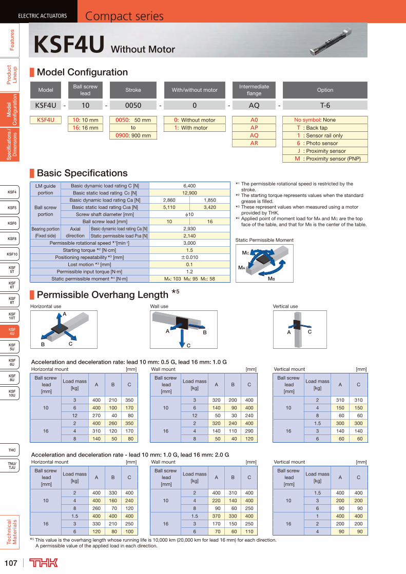
107
ELECTRIC ACTUATORS Compact seriesP
rod
uct
Line
upTe
ch
nic
al
Ma
teri
als
KSF8
KSF4
KSF 10T
KSF10
KSF 5T
KSF 6T
KSF 8T
KSF 10U
KSF 5U
KSF 6U
KSF 8U
TNU/TJU
THC
Spec
ifica
tions
/ D
imen
sion
sM
odel
C
onfig
urat
ion
Fea
ture
sELECTRIC ACTUATORS Compact series
KSF5
KSF6
ELECTRIC ACTUATORS Compact series
KSF 4U
KSF5
ELECTRIC ACTUATORS Compact series
KSF4U Without Motor
Model Configuration
ModelBall screw
leadStroke With/without motor
Intermediate flange
Option
KSF4U - 10 - 0050 - 0 - AQ - T-6
KSF4U 10: 10 mm 0050: 50 mm 0: Without motor A0 No symbol: None
16: 16 mm to 1: With motor AP T : Back tap0900: 900 mm AQ 1 : Sensor rail only
AR 6 : Photo sensor J : Proximity sensor M : Proximity sensor (PNP)
Basic SpecificationsLM guide portion
Basic dynamic load rating C [N] 6,400
Basic static load rating C0 [N] 12,900
Ball screw portion
Basic dynamic load rating Ca [N] 2,860 1,850
Basic static load rating C0a [N] 5,110 3,420
Screw shaft diameter [mm] 10
Ball screw lead [mm] 10 16
Bearing portion (Fixed side)
Axial direction
Basic dynamic load rating Ca [N] 2,930
Static permissible load P0a [N] 2,140
Permissible rotational speed 1[min-1] 3,000
Starting torque 2 [N·cm] 1.5
Positioning repeatability 3 [mm] ±0.010
Lost motion 3 [mm] 0.1
Permissible input torque [N·m] 1.2
Static permissible moment 4 [N·m] MA: 103 MB: 95 MC: 58
Permissible Overhang Length 5
Horizontal use Wall use Vertical use
CB
A
A B
C
A C
Acceleration and deceleration rate: lead 10 mm: 0.5 G, lead 16 mm: 1.0 GHorizontal mount [mm] Wall mount [mm] Vertical mount [mm]
Ball screw lead [mm]
Load mass [kg]
A B CBall screw
lead [mm]
Load mass [kg]
A B CBall screw
lead [mm]
Load mass [kg]
A C
10
3 400 210 350
10
3 320 200 400
10
2 310 310
6 400 100 170 6 140 90 400 4 150 150
12 270 40 80 12 50 30 240 8 60 60
16
2 400 260 350
16
2 320 240 400
16
1.5 300 300
4 310 120 170 4 140 110 290 3 140 140
8 140 50 80 8 50 40 120 6 60 60
Acceleration and deceleration rate - lead 10 mm: 1.0 G, lead 16 mm: 2.0 GHorizontal mount [mm] Wall mount [mm] Vertical mount [mm]
Ball screw lead [mm]
Load mass [kg]
A B CBall screw
lead [mm]
Load mass [kg]
A B CBall screw
lead [mm]
Load mass [kg]
A C
10
2 400 330 400
10
2 400 310 400
10
1.5 400 400
4 400 160 240 4 220 140 400 3 200 200
8 260 70 120 8 90 60 250 6 90 90
16
1.5 400 400 400
16
1.5 370 330 400
16
1 400 400
3 330 210 250 3 170 150 250 2 200 200
6 120 80 100 6 70 60 110 4 90 905 This value is the overhang length whose running life is 10,000 km (20,000 km for lead 16 mm) for each direction.
A permissible value of the applied load in each direction.
MB
MA
MC
Static Permissible Moment
1 The permissible rotational speed is restricted by the stroke.
2 The starting torque represents values when the standard grease is filled.
3 These represent values when measured using a motor provided by THK.
4 Applied point of moment load for MA and MC are the top face of the table, and that for MB is the center of the table.

108
ELECTRIC ACTUATORSCompact series
Pro
duc
t Li
neup
Tec
hn
ica
l M
ate
ria
ls
THC
TNU/TJU
KSF8
KSF4
KSF 10T
KSF10
KSF 5T
KSF 6T
KSF 8T
KSF 10U
KSF 5U
KSF 6U
KSF 8U
Spec
ifica
tions
/ D
imen
sion
sM
odel
C
onfig
urat
ion
Fea
ture
s
ELECTRIC ACTUATORSCompact series
KSF5
KSF6
ELECTRIC ACTUATORSCompact series
KSF 4U
KSF5
ELECTRIC ACTUATORSCompact series
KSF4U
Dimensions
Stroke [mm] (Stroke between mechanical stoppers)
50 (70)
100 (120)
150 (170)
200 (220)
250 (270)
300 (320)
350 (370)
400 (420)
450 (470)
Maximum speed 3 [mm/s]
Ball screw lead: 10 mm 500Ball screw lead: 16 mm 800
Dimensions [mm]
AL 283 333 383 433 483 533 583 633 683G 41 66 91 56 81 46 71 96 61H1 48 48 48 63 63 63 48 48 48H2 75 125 175 225 275 325 375 425 475P 150 200 250 150 175 200 225 250 275F 150 200 250 300 350 400 450 500 550
Mounting pitch count N 1 1 1 2 2 3 3 3 4
Mounting hole countn 2 2 2 3 3 4 4 4 5n1 2 2 2 3 3 3 3 3 3
Weight [kg] 1.3 1.5 1.6 1.8 2.0 2.1 2.3 2.4 2.6Stroke [mm]
(Stroke between mechanical stoppers)500 (520)
550 (570)
600 (620)
650 (670)
700 (720)
750 (770)
800 (820)
850 (870)
900 (920)
Maximum speed 3 [mm/s]
Ball screw lead: 10 mm 500 430 370 320 290 250 230 200Ball screw lead: 16 mm 800 690 600 520 460 410 360 330
Dimensions [mm]
AL 733 783 833 883 933 983 1033 1083 1133G 86 51 76 41 66 91 56 81 46H1 63 63 63 48 48 48 63 63 63H2 525 575 625 675 725 775 825 875 925P 200 130 175 150 200 170 150 190 200F 600 650 700 750 800 850 900 950 1000
Mounting pitch count N 4 5 5 6 6 6 7 7 8
Mounting hole countn 5 6 6 7 7 7 8 8 9n1 4 6 5 6 5 6 7 6 6
Weight [kg] 2.8 2.9 3.1 3.2 3.4 3.6 3.7 3.9 4.03 The maximum speed is the value restricted by the motor rotational speed (at 3000 min-1) or by the permissible rotational speed of the ball screw.
1 Stroke up to mechanical stopper.2 See P.135 for intermediate flange dimensions.
Detailed Diagram: Elongated Hole
Detailed drawing of motor mounting part (when A0 is selected) 2 A-A cross section
A
A
Detailed Diagram: Inner Block
B
342- 3.4 through
(Intermediate flange mounting hole)
G N × 120
120
From surface B2 × n- 3.4 through 6.5 counter bore Depth 3
(Outer rail mounting hole)
PCD40
2-M3 Depth 6(Intermediate flange mounting hole)
69
(R)(R)
1 1
4+0.
030
0
Elongated hole Depth 4
4H7 + 0.012 0 Depth 4 (drilled through pilot hole)
(Dowel pin hole)H1 H2
(AL)
(10) 1
25 13
3
30H
7+0.
021
0
6H7-
0.01
2 0
23.8
5
28
5.5
7
111825
15.8
40
2-(R2)
386.
85
18.9
9.2
60
10
2 (Sen
sor
dog
m
ount
ing
surf
ace)
(10) 1
(115) Stroke (58)
104
(1.5
)(1
.5)
14±
0.02
(Dim
ensi
onal
to
lera
nce
is
app
licab
le t
o
3 on
ly)
34±0.02
50
2- 3H7 Depth 5.5(Dowel pin hole)
2-M2.6 Depth 4.5 (Mouth C1)(Sensor dog mounting hole)
4-M4 Depth 8(Inner block mounting holes)
43
44.8
5
(G)
26
P
(n1-1) × P = F (26)
10.3
5
2 × n1 - M2.6 Depth 3.5 (same position as opposite side)(Sensor rail mounting holes)
30°
22
(45.4)
0+0.010
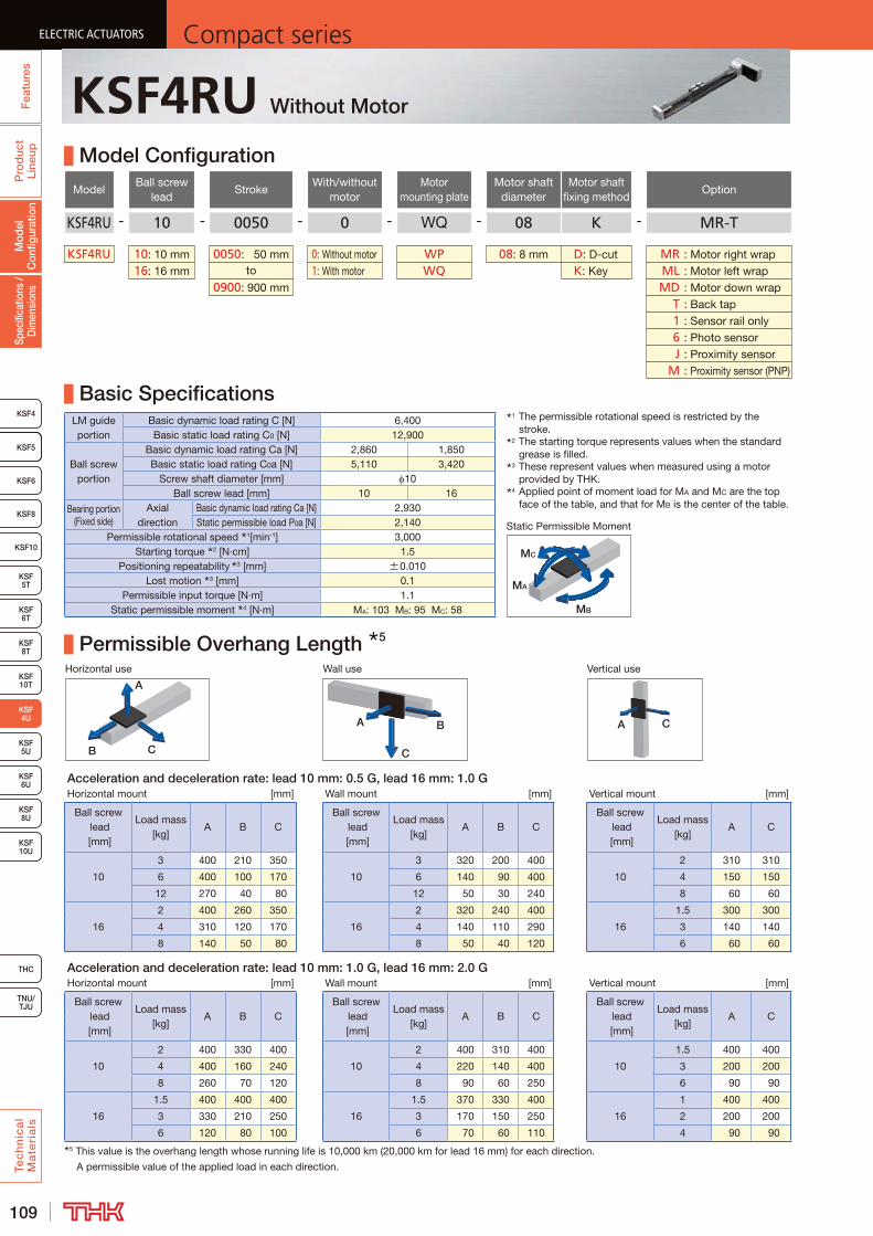
109
ELECTRIC ACTUATORS Compact seriesP
rod
uct
Line
upTe
ch
nic
al
Ma
teri
als
KSF8
KSF4
KSF 10T
KSF10
KSF 5T
KSF 6T
KSF 8T
KSF 10U
KSF 5U
KSF 6U
KSF 8U
TNU/TJU
THC
Spec
ifica
tions
/ D
imen
sion
sM
odel
C
onfig
urat
ion
Fea
ture
sELECTRIC ACTUATORS Compact series
KSF5
KSF6
ELECTRIC ACTUATORS Compact series
KSF 4U
KSF5
ELECTRIC ACTUATORS Compact series
KSF4RU Without Motor
Model Configuration
ModelBall screw
leadStroke
With/without motor
Motor mounting plate
Motor shaft diameter
Motor shaft fixing method
Option
KSF4RU - 10 - 0050 - 0 - WQ - 08 K - MR-T
KSF4RU 10: 10 mm 0050: 50 mm 0: Without motor WP 08: 8 mm D: D-cut MR : Motor right wrap16: 16 mm to 1: With motor WQ K: Key ML : Motor left wrap
0900: 900 mm MD : Motor down wrap T : Back tap 1 : Sensor rail only 6 : Photo sensor J : Proximity sensor M : Proximity sensor (PNP)
Basic SpecificationsLM guide portion
Basic dynamic load rating C [N] 6,400Basic static load rating C0 [N] 12,900
Ball screw portion
Basic dynamic load rating Ca [N] 2,860 1,850Basic static load rating C0a [N] 5,110 3,420
Screw shaft diameter [mm] 10Ball screw lead [mm] 10 16
Bearing portion (Fixed side)
Axial direction
Basic dynamic load rating Ca [N] 2,930Static permissible load P0a [N] 2,140
Permissible rotational speed 1[min-1] 3,000Starting torque 2 [N·cm] 1.5
Positioning repeatability 3 [mm] ±0.010Lost motion 3 [mm] 0.1
Permissible input torque [N·m] 1.1Static permissible moment 4 [N·m] MA: 103 MB: 95 MC: 58
Permissible Overhang Length 5
Horizontal use Wall use Vertical use
CB
A
A B
C
A C
Acceleration and deceleration rate: lead 10 mm: 0.5 G, lead 16 mm: 1.0 GHorizontal mount [mm] Wall mount [mm] Vertical mount [mm]
Ball screw lead [mm]
Load mass [kg]
A B CBall screw
lead [mm]
Load mass [kg]
A B CBall screw
lead [mm]
Load mass [kg]
A C
10
3 400 210 350
10
3 320 200 400
10
2 310 310
6 400 100 170 6 140 90 400 4 150 150
12 270 40 80 12 50 30 240 8 60 60
16
2 400 260 350
16
2 320 240 400
16
1.5 300 300
4 310 120 170 4 140 110 290 3 140 140
8 140 50 80 8 50 40 120 6 60 60
Acceleration and deceleration rate: lead 10 mm: 1.0 G, lead 16 mm: 2.0 GHorizontal mount [mm] Wall mount [mm] Vertical mount [mm]
Ball screw lead [mm]
Load mass [kg]
A B CBall screw
lead [mm]
Load mass [kg]
A B CBall screw
lead [mm]
Load mass [kg]
A C
10
2 400 330 400
10
2 400 310 400
10
1.5 400 400
4 400 160 240 4 220 140 400 3 200 200
8 260 70 120 8 90 60 250 6 90 90
16
1.5 400 400 400
16
1.5 370 330 400
16
1 400 400
3 330 210 250 3 170 150 250 2 200 200
6 120 80 100 6 70 60 110 4 90 905 This value is the overhang length whose running life is 10,000 km (20,000 km for lead 16 mm) for each direction.
A permissible value of the applied load in each direction.
MB
MA
MC
Static Permissible Moment
1 The permissible rotational speed is restricted by the stroke.
2 The starting torque represents values when the standard grease is filled.
3 These represent values when measured using a motor provided by THK.
4 Applied point of moment load for MA and MC are the top face of the table, and that for MB is the center of the table.
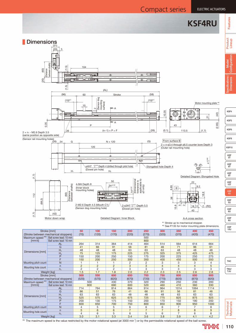
110
ELECTRIC ACTUATORSCompact series
Pro
duc
t Li
neup
Tec
hn
ica
l M
ate
ria
ls
THC
TNU/TJU
KSF8
KSF4
KSF 10T
KSF10
KSF 5T
KSF 6T
KSF 8T
KSF 10U
KSF 5U
KSF 6U
KSF 8U
Spec
ifica
tions
/ D
imen
sion
sM
odel
C
onfig
urat
ion
Fea
ture
s
ELECTRIC ACTUATORSCompact series
KSF5
KSF6
ELECTRIC ACTUATORSCompact series
KSF 4U
KSF5
ELECTRIC ACTUATORSCompact series
KSF4RU
Dimensions
Stroke [mm] (Stroke between mechanical stoppers)
50 (70)
100 (120)
150 (170)
200 (220)
250 (270)
300 (320)
350 (370)
400 (420)
450 (470)
Maximum speed 3 [mm/s]
Ball screw lead: 10 mm 500Ball screw lead: 16 mm 800
Dimensions [mm]
AL 264 314 364 414 464 514 564 614 664G 41 66 91 56 81 46 71 96 61H1 48 48 48 63 63 63 48 48 48H2 75 125 175 225 275 325 375 425 475P 150 200 250 150 175 200 225 250 275F 150 200 250 300 350 400 450 500 550
Mounting pitch count N 1 1 1 2 2 3 3 3 4
Mounting hole count n 2 2 2 3 3 4 4 4 5n1 2 2 2 3 3 3 3 3 3
Weight [kg] 1.5 1.7 1.8 2.0 2.2 2.3 2.5 2.6 2.8Stroke [mm]
(Stroke between mechanical stoppers)500 (520)
550 (570)
600 (620)
650 (670)
700 (720)
750 (770)
800 (820)
850 (870)
900 (920)
Maximum speed 3 [mm/s]
Ball screw lead: 10 mm 500 430 370 320 290 250 230 200Ball screw lead: 16 mm 800 690 600 520 460 410 360 330
Dimensions [mm]
AL 714 764 814 864 914 964 1014 1064 1114G 86 51 76 41 66 91 56 81 46H1 63 63 63 48 48 48 63 63 63H2 525 575 625 675 725 775 825 875 925P 200 130 175 150 200 170 150 190 200F 600 650 700 750 800 850 900 950 1000
Mounting pitch count N 4 5 5 6 6 6 7 7 8
Mounting hole count n 5 6 6 7 7 7 8 8 9n1 4 6 5 6 5 6 7 6 6
Weight [kg] 3.0 3.1 3.3 3.4 3.6 3.8 3.9 4.1 4.23 The maximum speed is the value restricted by the motor rotational speed (at 3000 min-1) or by the permissible rotational speed of the ball screw.
1 Stroke up to mechanical stopper.2 See P.135 for motor mounting plate dimensions.
A
A
From surface B
Detailed Diagram: Inner BlockMotor down wrap A-A cross section
B
4H7 +0.012 0 Depth 4 (drilled through pilot hole)
(Dowel pin hole)
G N × 120
120
(26)
10.3
5
(n1-1) × P = F
(58)
2 × n1 - M2.6 Depth 3.5 (same position as opposite side)
(Sensor rail mounting holes)
10
60
26
P
2
(AL)
Stroke
(10) 1 (10) 1
2 × n- 3.4 through 6.5 counter bore Depth 3(Outer rail mounting hole)
(96)
Elongated hole Depth 4
H2
4-M4 Depth 8(Inner block mounting holes)
Detailed Diagram: Elongated Hole
4+
0.03
0 0
1 1
(R) (R)
H1
50
2- 3H7 +0.010 0 Depth 5.5
(Dowel pin hole)
2-M2.6 Depth 4.5 (Mouth C1)(Sensor dog mounting hole)
34±0.02
14±
0.02
(Dim
ensi
onal
to
lera
nce
is
app
licab
le t
o 3
only
)(G)
112
(68.
2)
(60)
(Dis
tanc
e b
etw
een
shaf
ts)
104(1
.5)
(1.5
)
5(20)
(31)(6
0)(D
istan
ce
betw
een
shaf
ts)
(20)
(1.7
)(1
.7)
(42)
(1.7)113.5
(42)
43
(0.1)
(2.8
5)
21
0.35
Motor mounting plate 2
24(26)
185 2 11
15.8 2 - (R2)
9.2
18.9
386.
85
40
22
(Sen
sor d
og
mou
ntin
g su
rfac
e)
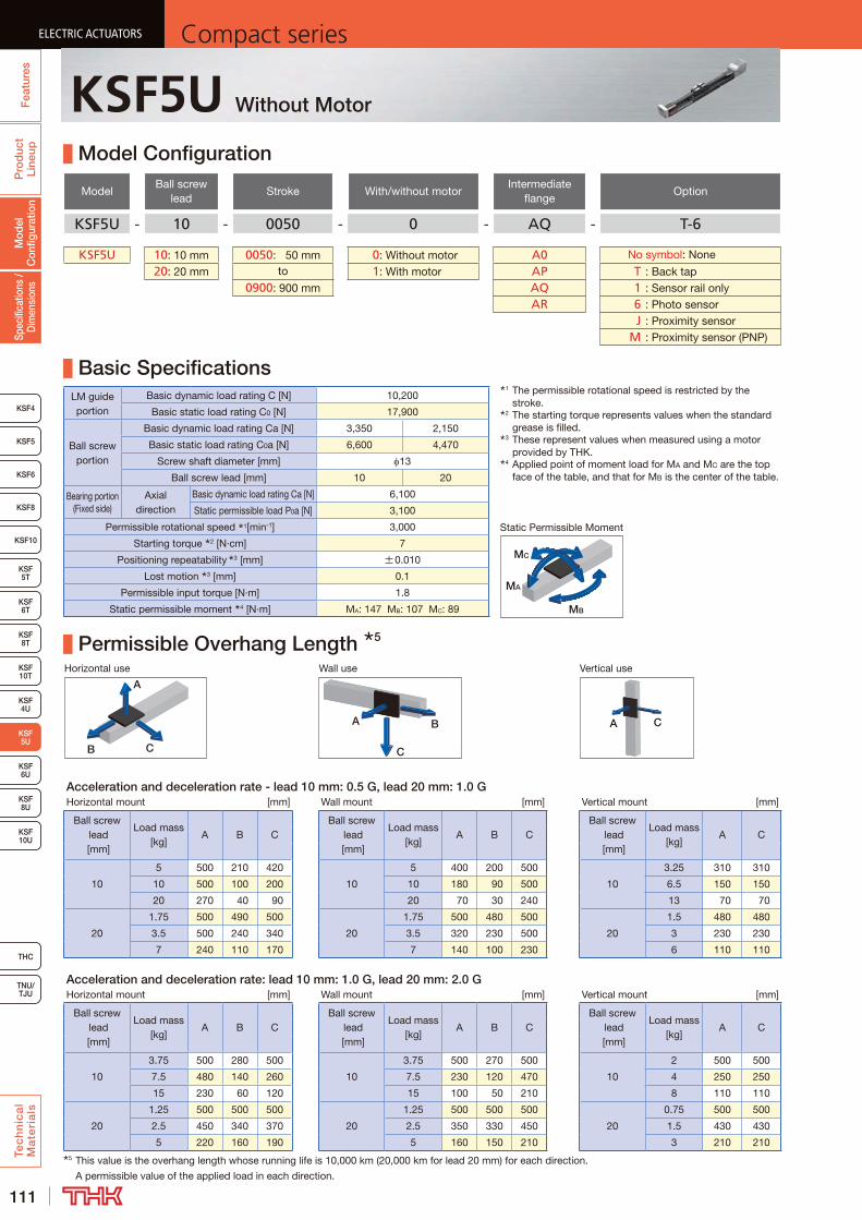
111
ELECTRIC ACTUATORS Compact seriesP
rod
uct
Line
upTe
ch
nic
al
Ma
teri
als
KSF8
KSF4
KSF 10T
KSF 5T
KSF 6T
KSF 8T
KSF 10U
KSF 4U
KSF 6U
KSF 8U
TNU/TJU
THC
Spec
ifica
tions
/ D
imen
sion
sM
odel
C
onfig
urat
ion
Fea
ture
sELECTRIC ACTUATORS Compact series
KSF5
KSF6
ELECTRIC ACTUATORS Compact series
KSF 5U
KSF10
ELECTRIC ACTUATORS Compact series
KSF5U Without Motor
Model Configuration
ModelBall screw
leadStroke With/without motor
Intermediate flange
Option
KSF5U - 10 - 0050 - 0 - AQ - T-6
KSF5U 10: 10 mm 0050: 50 mm 0: Without motor A0 No symbol: None
20: 20 mm to 1: With motor AP T : Back tap0900: 900 mm AQ 1 : Sensor rail only
AR 6 : Photo sensor J : Proximity sensor M : Proximity sensor (PNP)
Basic SpecificationsLM guide portion
Basic dynamic load rating C [N] 10,200
Basic static load rating C0 [N] 17,900
Ball screw portion
Basic dynamic load rating Ca [N] 3,350 2,150
Basic static load rating C0a [N] 6,600 4,470
Screw shaft diameter [mm] 13
Ball screw lead [mm] 10 20
Bearing portion (Fixed side)
Axial direction
Basic dynamic load rating Ca [N] 6,100
Static permissible load P0a [N] 3,100
Permissible rotational speed 1[min-1] 3,000
Starting torque 2 [N·cm] 7
Positioning repeatability 3 [mm] ±0.010
Lost motion 3 [mm] 0.1
Permissible input torque [N·m] 1.8
Static permissible moment 4 [N·m] MA: 147 MB: 107 MC: 89
Permissible Overhang Length 5
Horizontal use Wall use Vertical use
CB
A
A B
C
A C
Acceleration and deceleration rate - lead 10 mm: 0.5 G, lead 20 mm: 1.0 GHorizontal mount [mm] Wall mount [mm] Vertical mount [mm]
Ball screw lead [mm]
Load mass [kg]
A B CBall screw
lead [mm]
Load mass [kg]
A B CBall screw
lead [mm]
Load mass [kg]
A C
10
5 500 210 420
10
5 400 200 500
10
3.25 310 310
10 500 100 200 10 180 90 500 6.5 150 150
20 270 40 90 20 70 30 240 13 70 70
20
1.75 500 490 500
20
1.75 500 480 500
20
1.5 480 480
3.5 500 240 340 3.5 320 230 500 3 230 230
7 240 110 170 7 140 100 230 6 110 110
Acceleration and deceleration rate: lead 10 mm: 1.0 G, lead 20 mm: 2.0 GHorizontal mount [mm] Wall mount [mm] Vertical mount [mm]
Ball screw lead [mm]
Load mass [kg]
A B CBall screw
lead [mm]
Load mass [kg]
A B CBall screw
lead [mm]
Load mass [kg]
A C
10
3.75 500 280 500
10
3.75 500 270 500
10
2 500 500
7.5 480 140 260 7.5 230 120 470 4 250 250
15 230 60 120 15 100 50 210 8 110 110
20
1.25 500 500 500
20
1.25 500 500 500
20
0.75 500 500
2.5 450 340 370 2.5 350 330 450 1.5 430 430
5 220 160 190 5 160 150 210 3 210 2105 This value is the overhang length whose running life is 10,000 km (20,000 km for lead 20 mm) for each direction.
A permissible value of the applied load in each direction.
MB
MA
MC
Static Permissible Moment
1 The permissible rotational speed is restricted by the stroke.
2 The starting torque represents values when the standard grease is filled.
3 These represent values when measured using a motor provided by THK.
4 Applied point of moment load for MA and MC are the top face of the table, and that for MB is the center of the table.
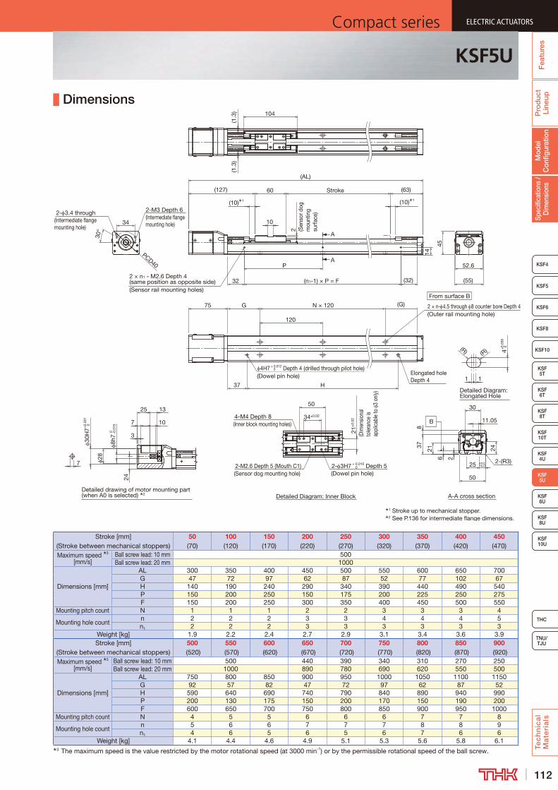
112
ELECTRIC ACTUATORSCompact series
Pro
duc
t Li
neup
Tec
hn
ica
l M
ate
ria
ls
THC
TNU/TJU
KSF8
KSF4
KSF 10T
KSF 5T
KSF 6T
KSF 8T
KSF 10U
KSF 4U
KSF 6U
KSF 8U
Spec
ifica
tions
/ D
imen
sion
sM
odel
C
onfig
urat
ion
Fea
ture
s
ELECTRIC ACTUATORSCompact series
KSF5
KSF6
ELECTRIC ACTUATORSCompact series
KSF 5U
KSF10
ELECTRIC ACTUATORSCompact series
KSF5U
Dimensions
Stroke [mm] (Stroke between mechanical stoppers)
50 (70)
100 (120)
150 (170)
200 (220)
250 (270)
300 (320)
350 (370)
400 (420)
450 (470)
Maximum speed 3 [mm/s]
Ball screw lead: 10 mm 500Ball screw lead: 20 mm 1000
Dimensions [mm]
AL 300 350 400 450 500 550 600 650 700G 47 72 97 62 87 52 77 102 67H 140 190 240 290 340 390 440 490 540P 150 200 250 150 175 200 225 250 275F 150 200 250 300 350 400 450 500 550
Mounting pitch count N 1 1 1 2 2 3 3 3 4
Mounting hole countn 2 2 2 3 3 4 4 4 5n1 2 2 2 3 3 3 3 3 3
Weight [kg] 1.9 2.2 2.4 2.7 2.9 3.1 3.4 3.6 3.9Stroke [mm]
(Stroke between mechanical stoppers)500
(520)550
(570)600
(620)650
(670)700
(720)750
(770)800
(820)850
(870)900
(920)Maximum speed 3
[mm/s]Ball screw lead: 10 mm 500 440 390 340 310 270 250Ball screw lead: 20 mm 1000 890 780 690 620 550 500
Dimensions [mm]
AL 750 800 850 900 950 1000 1050 1100 1150G 92 57 82 47 72 97 62 87 52H 590 640 690 740 790 840 890 940 990P 200 130 175 150 200 170 150 190 200F 600 650 700 750 800 850 900 950 1000
Mounting pitch count N 4 5 5 6 6 6 7 7 8
Mounting hole countn 5 6 6 7 7 7 8 8 9n1 4 6 5 6 5 6 7 6 6
Weight [kg] 4.1 4.4 4.6 4.9 5.1 5.3 5.6 5.8 6.13 The maximum speed is the value restricted by the motor rotational speed (at 3000 min-1) or by the permissible rotational speed of the ball screw.
From surface B
Detailed Diagram: Inner Block
1 Stroke up to mechanical stopper.2 See P.136 for intermediate flange dimensions.
Detailed drawing of motor mounting part (when A0 is selected) 2
Detailed Diagram: Elongated Hole
A-A cross section
A
A
B
52.6
(127)
2 (Sen
sor d
og
mou
ntin
g su
rface
)
(63)Stroke
(10) 1(10) 1
60
10
25
(AL)
50
37
N × 120
120
G
H
(G)
11.05
24
837
21
6 2
12.5
Elongated hole Depth 4
2 × n- 4.5 through 8 counter bore Depth 4(Outer rail mounting hole)
2-(R3)2-M2.6 Depth 5 (Mouth C1)(Sensor dog mounting hole)
4-M4 Depth 8(Inner block mounting holes)
(Dowel pin hole)
2- 3H7 + 0.010 Depth 5 0
(Dowel pin hole)
21±
0.02
(Dim
ensio
nal
tole
ranc
e is
appl
icab
le to
3
only)
34±0.02
50
(R) (R)
1
4+0.
030
0
1
10
30H
7+0.
021
7
24
25
7
8h7
0 -0.0
15
28
13
3
4H7 + 0.012 Depth 4 (drilled through pilot hole) 0
45
14PCD40
34
2- 3.4 through(Intermediate flange mounting hole)
2-M3 Depth 6(Intermediate flange mounting hole)
32
P
(32)(n1-1) × P = F2 × n1 - M2.6 Depth 4 (same position as opposite side)(Sensor rail mounting holes)
30
30°
(1.3
)(1
.3) 104
75
(55)
0

113
ELECTRIC ACTUATORS Compact seriesP
rod
uct
Line
upTe
ch
nic
al
Ma
teri
als
KSF8
KSF4
KSF 10T
KSF 5T
KSF 6T
KSF 8T
KSF 10U
KSF 4U
KSF 6U
KSF 8U
TNU/TJU
THC
Spec
ifica
tions
/ D
imen
sion
sM
odel
C
onfig
urat
ion
Fea
ture
sELECTRIC ACTUATORS Compact series
KSF5
KSF6
ELECTRIC ACTUATORS Compact series
KSF 5U
KSF10
ELECTRIC ACTUATORS Compact series
KSF5RU Without Motor
Model Configuration
ModelBall screw
leadStroke
With/without motor
Motor mounting plate
Motor shaft diameter
Motor shaft fixing method
Option
KSF5RU - 10 - 0050 - 0 - WQ - 08 K - MR-T
KSF5RU 10: 10 mm 0050: 50 mm 0: Without motor WP 08: 8 mm D: D-cut MR : Motor right wrap20: 20 mm to 1: With motor WQ K: Key ML : Motor left wrap
0900: 900 mm MD : Motor down wrap T : Back tap 1 : Sensor rail only 6 : Photo sensor J : Proximity sensor M : Proximity sensor (PNP)
Basic SpecificationsLM guide portion
Basic dynamic load rating C [N] 10,200Basic static load rating C0 [N] 17,900
Ball screw portion
Basic dynamic load rating Ca [N] 3,350 2,150Basic static load rating C0a [N] 6,600 4,470
Screw shaft diameter [mm] 13Ball screw lead [mm] 10 20
Bearing portion (Fixed side)
Axial direction
Basic dynamic load rating Ca [N] 6,100Static permissible load P0a [N] 3,100
Permissible rotational speed 1[min-1] 3,000Starting torque 2 [N·cm] 7
Positioning repeatability 3 [mm] ±0.010Lost motion 3 [mm] 0.1
Permissible input torque [N·m] 1.1Static permissible moment 4 [N·m] MA: 147 MB: 107 MC: 89
Permissible Overhang Length 5
Horizontal use Wall use Vertical use
CB
A
A B
C
A C
Acceleration and deceleration rate - lead 10 mm: 0.5 G, lead 20 mm: 1.0 GHorizontal mount [mm] Wall mount [mm] Vertical mount [mm]
Ball screw lead [mm]
Load mass [kg]
A B CBall screw
lead [mm]
Load mass [kg]
A B CBall screw
lead [mm]
Load mass [kg]
A C
10
5 500 210 420
10
5 400 200 500
10
2.75 380 380
10 500 100 200 10 180 90 500 5.5 180 180
20 270 40 90 20 70 30 240 11 80 80
20
1.75 500 490 500
20
1.75 500 480 500
20
1.25 500 500
3.5 500 240 340 3.5 320 230 500 2.5 280 280
7 240 110 170 7 140 100 230 5 130 130
Acceleration and deceleration rate - lead 10 mm: 1.0 G, lead 20 mm: 2.0 GHorizontal mount [mm] Wall mount [mm] Vertical mount [mm]
Ball screw lead [mm]
Load mass [kg]
A B CBall screw
lead [mm]
Load mass [kg]
A B CBall screw
lead [mm]
Load mass [kg]
A C
10
3.75 500 280 500
10
3.75 500 270 500
10
2 500 500
7.5 480 140 260 7.5 230 120 470 4 250 250
15 230 60 120 15 100 50 210 8 110 110
20
1 500 500 500
20
1 500 500 500
20
0.625 500 500
2 500 430 470 2 440 410 500 1.25 500 500
4 270 210 230 4 210 200 270 2.5 250 2505 This value is the overhang length whose running life is 10,000 km (20,000 km for lead 20 mm) for each direction.
A permissible value of the applied load in each direction.
MB
MA
MC
Static Permissible Moment
1 The permissible rotational speed is restricted by the stroke.
2 The starting torque represents values when the standard grease is filled.
3 These represent values when measured using a motor provided by THK.
4 Applied point of moment load for MA and MC are the top face of the table, and that for MB is the center of the table.
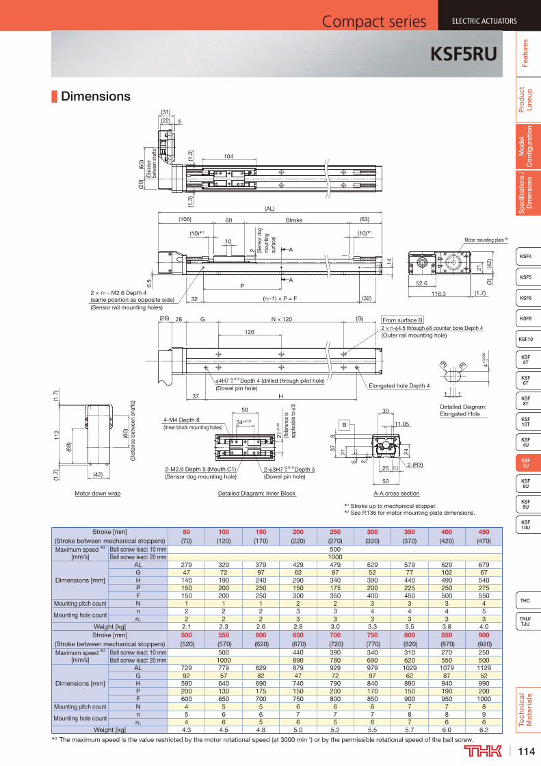
114
ELECTRIC ACTUATORSCompact series
Pro
duc
t Li
neup
Tec
hn
ica
l M
ate
ria
ls
THC
TNU/TJU
KSF8
KSF4
KSF 10T
KSF 5T
KSF 6T
KSF 8T
KSF 10U
KSF 4U
KSF 6U
KSF 8U
Spec
ifica
tions
/ D
imen
sion
sM
odel
C
onfig
urat
ion
Fea
ture
s
ELECTRIC ACTUATORSCompact series
KSF5
KSF6
ELECTRIC ACTUATORSCompact series
KSF 5U
KSF10
ELECTRIC ACTUATORSCompact series
KSF5RU
Dimensions
Stroke [mm] (Stroke between mechanical stoppers)
50 (70)
100 (120)
150 (170)
200 (220)
250 (270)
300 (320)
350 (370)
400 (420)
450 (470)
Maximum speed 3 [mm/s]
Ball screw lead: 10 mm 500Ball screw lead: 20 mm 1000
Dimensions [mm]
AL 279 329 379 429 479 529 579 629 679G 47 72 97 62 87 52 77 102 67H 140 190 240 290 340 390 440 490 540P 150 200 250 150 175 200 225 250 275F 150 200 250 300 350 400 450 500 550
Mounting pitch count N 1 1 1 2 2 3 3 3 4
Mounting hole countn 2 2 2 3 3 4 4 4 5n1 2 2 2 3 3 3 3 3 3
Weight [kg] 2.1 2.3 2.6 2.8 3.0 3.3 3.5 3.8 4.0Stroke [mm]
(Stroke between mechanical stoppers)500
(520)550
(570)600
(620)650
(670)700
(720)750
(770)800
(820)850
(870)900
(920)Maximum speed 3
[mm/s]Ball screw lead: 10 mm 500 440 390 340 310 270 250Ball screw lead: 20 mm 1000 890 780 690 620 550 500
Dimensions [mm]
AL 729 779 829 879 929 979 1029 1079 1129G 92 57 82 47 72 97 62 87 52H 590 640 690 740 790 840 890 940 990P 200 130 175 150 200 170 150 190 200F 600 650 700 750 800 850 900 950 1000
Mounting pitch count N 4 5 5 6 6 6 7 7 8
Mounting hole countn 5 6 6 7 7 7 8 8 9n1 4 6 5 6 5 6 7 6 6
Weight [kg] 4.3 4.5 4.8 5.0 5.2 5.5 5.7 6.0 6.23 The maximum speed is the value restricted by the motor rotational speed (at 3000 min-1) or by the permissible rotational speed of the ball screw.
From surface B
Depth 4 (drilled through pilot hole)
1 Stroke up to mechanical stopper.2 See P.136 for motor mounting plate dimensions.
Motor down wrap Detailed Diagram: Inner Block
A
A
A-A cross section
B
(63)60
10
2 (Sen
sor d
og
mou
ntin
g su
rface
)
Stroke
(10) 1(10) 1
(AL)
14
(1.7)
(42)
(3)
37
21
118.3
(G)
H
G
120
N × 120
Elongated hole Depth 4
2 × n- 4.5 through 8 counter bore Depth 4(Outer rail mounting hole)
2-M2.6 Depth 5 (Mouth C1)(Sensor dog mounting hole)
4-M4 Depth 8(Inner block mounting holes)
2- 3H7+0.010 0 Depth 5
(Dowel pin hole)
21±
0.02
34±0.02
50 Detailed Diagram: Elongated Hole
(R) (R)
1
4+
0.03
0 0
1
4H7+0.012 0
(Dowel pin hole)
52.6
32
P
(32)(n1-1) × P = F
(106)
28(26)
2 × n1 - M2.6 Depth 4 (same position as opposite side)(Sensor rail mounting holes)
(1.7
)11
2(1
.7)
(42)
(68)
(60)
(Dis
tanc
e be
twee
n sh
afts
)
(1.3
)(1
.3)
104
5(22)
(31)
(20)
(60)
(Dist
ance
be
twee
n sh
afts
)0.
5
Motor mounting plate 2
252-(R3)
12.5
30
2
21
378
24
11.05
6
50
(Tole
ranc
e is
appl
icab
le to
3)
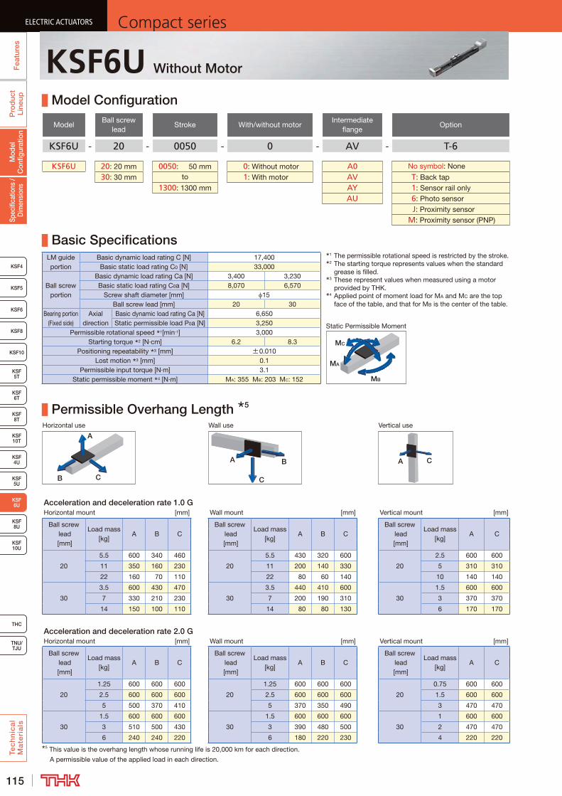
115
ELECTRIC ACTUATORS Compact seriesP
rod
uct
Line
upTe
ch
nic
al
Ma
teri
als
KSF8
KSF4
KSF 10T
KSF10
KSF 5T
KSF 6T
KSF 10U
KSF 4U
KSF 5U
KSF 8U
TNU/TJU
THC
Spec
ifica
tions
/ D
imen
sion
sM
odel
C
onfig
urat
ion
Fea
ture
sELECTRIC ACTUATORS Compact series
KSF5
KSF6
ELECTRIC ACTUATORS Compact series
KSF 6U
KSF8T
ELECTRIC ACTUATORS Compact series
KSF6U Without Motor
Model Configuration
ModelBall screw
leadStroke With/without motor
Intermediate flange
Option
KSF6U - 20 - 0050 - 0 - AV - T-6
KSF6U 20: 20 mm 0050: 50 mm 0: Without motor A0 No symbol: None
30: 30 mm to 1: With motor AV T : Back tap1300: 1300 mm AY 1 : Sensor rail only
AU 6 : Photo sensor J : Proximity sensor M : Proximity sensor (PNP)
Basic SpecificationsLM guide portion
Basic dynamic load rating C [N] 17,400Basic static load rating C0 [N] 33,000
Ball screw portion
Basic dynamic load rating Ca [N] 3,400 3,230Basic static load rating C0a [N] 8,070 6,570
Screw shaft diameter [mm] 15Ball screw lead [mm] 20 30
Bearing portion (Fixed side)
Axial direction
Basic dynamic load rating Ca [N] 6,650Static permissible load P0a [N] 3,250
Permissible rotational speed 1[min-1] 3,000Starting torque 2 [N·cm] 6.2 8.3
Positioning repeatability 3 [mm] ±0.010Lost motion 3 [mm] 0.1
Permissible input torque [N·m] 3.1Static permissible moment 4 [N·m] MA: 355 MB: 203 MC: 152
Permissible Overhang Length 5
Horizontal use Wall use Vertical use
CB
A
A B
C
A C
Acceleration and deceleration rate 1.0 GHorizontal mount [mm] Wall mount [mm] Vertical mount [mm]
Ball screw lead [mm]
Load mass [kg]
A B CBall screw
lead [mm]
Load mass [kg]
A B CBall screw
lead [mm]
Load mass [kg]
A C
20
5.5 600 340 460
20
5.5 430 320 600
20
2.5 600 600
11 350 160 230 11 200 140 330 5 310 310
22 160 70 110 22 80 60 140 10 140 140
30
3.5 600 430 470
30
3.5 440 410 600
30
1.5 600 600
7 330 210 230 7 200 190 310 3 370 370
14 150 100 110 14 80 80 130 6 170 170
Acceleration and deceleration rate 2.0 GHorizontal mount [mm] Wall mount [mm] Vertical mount [mm]
Ball screw lead [mm]
Load mass [kg]
A B CBall screw
lead [mm]
Load mass [kg]
A B CBall screw
lead [mm]
Load mass [kg]
A C
20
1.25 600 600 600
20
1.25 600 600 600
20
0.75 600 600
2.5 600 600 600 2.5 600 600 600 1.5 600 600
5 500 370 410 5 370 350 490 3 470 470
30
1.5 600 600 600
30
1.5 600 600 600
30
1 600 600
3 510 500 430 3 390 480 500 2 470 470
6 240 240 220 6 180 220 230 4 220 2205 This value is the overhang length whose running life is 20,000 km for each direction.
A permissible value of the applied load in each direction.
MB
MA
MC
Static Permissible Moment
1 The permissible rotational speed is restricted by the stroke.2 The starting torque represents values when the standard
grease is filled.3 These represent values when measured using a motor
provided by THK.4 Applied point of moment load for MA and MC are the top
face of the table, and that for MB is the center of the table.
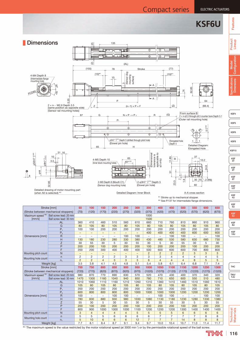
116
ELECTRIC ACTUATORSCompact series
Pro
duc
t Li
neup
Tec
hn
ica
l M
ate
ria
ls
THC
TNU/TJU
KSF8
KSF4
KSF 10T
KSF10
KSF 5T
KSF 6T
KSF 10U
KSF 4U
KSF 5U
KSF 8U
Spec
ifica
tions
/ D
imen
sion
sM
odel
C
onfig
urat
ion
Fea
ture
s
ELECTRIC ACTUATORSCompact series
KSF5
KSF6
ELECTRIC ACTUATORSCompact series
KSF 6U
KSF8T
ELECTRIC ACTUATORSCompact series
KSF6U
Dimensions
Stroke [mm] (Stroke between mechanical stoppers)
50 (70)
100 (120)
150 (170)
200 (220)
250 (270)
300 (320)
350 (370)
400 (420)
450 (470)
500 (520)
550 (570)
600 (620)
650 (670)
Maximum speed 3 [mm/s]
Ball screw lead: 20 mm 1000Ball screw lead: 30 mm 1500
Dimensions [mm]
AL 360 410 460 510 560 610 660 710 760 810 860 910 960G 80 105 80 105 80 105 80 105 80 105 80 105 80P1 100 100 200 200 200 200 200 200 200 200 200 200 200P2 − − − − − − 400 400 400 400 600 600 600R − − − − 100 100 − − 100 100 − − 100H 130 180 230 280 330 380 430 480 530 580 630 680 730Z 30 55 30 5 30 55 30 5 30 55 30 5 30P 200 200 100 200 200 200 100 200 200 200 100 200 200F 200 200 300 400 400 400 500 600 600 600 700 800 800
Mounting pitch count N − − − − − − 2 2 2 2 3 3 3
Mounting hole countn 2 2 2 2 3 3 3 3 4 4 4 4 5n1 2 2 4 3 3 3 6 4 4 4 8 5 5
Weight [kg] 3.5 3.8 4.1 4.5 4.8 5.1 5.4 5.8 6.1 6.4 6.8 7.1 7.4Stroke [mm]
(Stroke between mechanical stoppers)700 (720)
750 (770)
800 (820)
850 (870)
900 (920)
950 (970)
1000 (1020)
1050 (1070)
1100 (1120)
1150 (1170)
1200 (1220)
1250 (1270)
1300 (1320)
Maximum speed 3 [mm/s]
Ball screw lead: 20 mm 980 870 770 690 630 570 520 470 430 400 370 340 320Ball screw lead: 30 mm 1470 1300 1160 1040 940 850 780 710 650 600 550 510 480
Dimensions [mm]
AL 1010 1060 1110 1160 1210 1260 1310 1360 1410 1460 1510 1560 1610G 105 80 105 80 105 80 105 80 105 80 105 80 105P1 200 200 200 200 200 200 200 200 200 200 200 200 200P2 600 800 800 800 800 1000 1000 1000 1000 1200 1200 1200 1200R 100 − − 100 100 − − 100 100 − − 100 100H 780 830 880 930 980 1030 1080 1130 1180 1230 1280 1330 1380Z 55 30 5 30 55 30 5 30 55 30 5 30 55P 200 100 200 200 200 100 200 200 200 100 200 200 200F 800 900 1000 1000 1000 1100 1200 1200 1200 1300 1400 1400 1400
Mounting pitch count N 3 4 4 4 4 5 5 5 5 6 6 6 6
Mounting hole countn 5 5 5 6 6 6 6 7 7 7 7 8 8n1 5 10 6 6 6 12 7 7 7 14 8 8 8
Weight [kg] 7.7 8.1 8.4 8.7 9.1 9.4 9.7 10.0 10.4 10.7 11.0 11.4 11.73 The maximum speed is the value restricted by the motor rotational speed (at 3000 min-1) or by the permissible rotational speed of the ball screw.
A
A
Detailed Diagram: Elongated Hole
A-A cross sectionDetailed drawing of motor mounting part (when A0 is selected) 2 Detailed Diagram: Inner Block
B
4-M4 Depth 8(Intermediate flange mounting hole)
0.35
30°30°
(10) 1
From surface B2 × n- 5.5 through 9.5 counter bore Depth 5.1(Outer rail mounting hole)
PCD60
(155)
N × P 1 = P 2 R (G)
62.8
5
64
5H7 + 0.012 Depth 5 (drilled through pilot hole) 0
(Dowel pin hole)
Stroke
87
(10) 1
78
P
2 × n1 - M2.6 Depth 3.5 (same position as opposite side)(Sensor rail mounting holes)
Z (Z)(n1-1) × P = F
3 (Sen
sor d
og
mou
ntin
g su
rface
)
10
65 H
(AL)
G
P1
(77)
Elongated hole Depth 5
10
1 1
5+
0.03
0 0
(R)(R)
2-M3 Depth 6 (Mouth C1)(Sensor dog mounting hole)
4-M5 Depth 10(Inner block mounting holes)
2- 3H7 + 0.010 Depth 5 0
(Dowel pin hole)
27±
0.02
(Dim
ensi
onal
to
lera
nce
is
app
licab
le t
o 3
only
)40±0.02
653.5
32.8
5
44
9h7
0 -0.0
15
31
50H
7+
0.02
5 0
16
1415
1.9
11.8
5
10.237
51
30
60
24.8
7
23.5
135(2)
(2)
2-(R6)
8
(66.4)
1 Stroke up to mechanical stopper.2 See P.137 for intermediate flange dimensions.

117
ELECTRIC ACTUATORS Compact seriesP
rod
uct
Line
upTe
ch
nic
al
Ma
teri
als
KSF8
KSF4
KSF 10T
KSF10
KSF 5T
KSF 6T
KSF 10U
KSF 4U
KSF 5U
KSF 8U
TNU/TJU
THC
Spec
ifica
tions
/ D
imen
sion
sM
odel
C
onfig
urat
ion
Fea
ture
sELECTRIC ACTUATORS Compact series
KSF5
KSF6
ELECTRIC ACTUATORS Compact series
KSF 6U
KSF8T
ELECTRIC ACTUATORS Compact series
KSF6RU Without Motor
Model Configuration
ModelBall screw
leadStroke
With/without motor
Motor mounting plate
Motor shaft diameter
Motor shaft fixing method
Option
KSF6RU - 20 - 0050 - 0 - WV - 14 K - MR-T
KSF6RU 20: 20 mm 0050: 50 mm 0: Without motor WV 11: 11 mm D: D-cut MR : Motor right wrap30: 30 mm to 1: With motor WY 14: 14 mm K: Key ML : Motor left wrap
1300: 1300 mm M: Friction tightening MD : Motor down wrap T : Back tap 1 : Sensor rail only 6 : Photo sensor J : Proximity sensor M : Proximity sensor (PNP)
Basic SpecificationsLM guide portion
Basic dynamic load rating C [N] 17,400Basic static load rating C0 [N] 33,000
Ball screw portion
Basic dynamic load rating Ca [N] 3,400 3,230Basic static load rating C0a [N] 8,070 6,570
Screw shaft diameter [mm] 15Ball screw lead [mm] 20 30
Bearing portion (Fixed side)
Axial direction
Basic dynamic load rating Ca [N] 6,650Static permissible load P0a [N] 3,250
Permissible rotational speed 1[min-1] 3,000Starting torque 2 [N·cm] 6.2 8.3
Positioning repeatability 3 [mm] ±0.010Lost motion 3 [mm] 0.1
Permissible input torque [N·m] 2.2Static permissible moment 4 [N·m] MA: 355 MB: 203 MC: 152
Permissible Overhang Length 5
Horizontal use Wall use Vertical use
CB
A
A B
C
A C
Acceleration and deceleration rate 1.0 GHorizontal mount [mm] Wall mount [mm] Vertical mount [mm]
Ball screw lead [mm]
Load mass [kg]
A B CBall screw
lead [mm]
Load mass [kg]
A B CBall screw
lead [mm]
Load mass [kg]
A C
20
4.75 600 340 460
20
4.75 430 320 600
20
2.25 600 600
9.5 350 160 230 9.5 200 140 330 4.5 310 310
19 160 70 110 19 80 60 140 9 140 140
30
2.75 600 430 470
30
2.75 440 410 600
30
1.25 600 600
5.5 330 210 230 5.5 200 190 310 2.5 370 370
11 150 100 110 11 80 80 130 5 170 170
Acceleration and deceleration rate 2.0 GHorizontal mount [mm] Wall mount [mm] Vertical mount [mm]
Ball screw lead [mm]
Load mass [kg]
A B CBall screw
lead [mm]
Load mass [kg]
A B CBall screw
lead [mm]
Load mass [kg]
A C
20
1 600 600 600
20
1 600 600 600
20
0.625 600 600
2 600 600 600 2 600 600 600 1.25 600 600
4 500 370 410 4 370 350 490 2.5 470 470
30
1 600 600 600
30
1 600 600 600
30
0.625 600 600
2 510 500 430 2 390 480 500 1.25 470 470
4 240 240 220 4 180 220 230 2.5 220 2205 This value is the overhang length whose running life is 20,000 km for each direction.
A permissible value of the applied load in each direction.
MB
MA
MC
Static Permissible Moment
1 The permissible rotational speed is restricted by the stroke.2 The starting torque represents values when the standard
grease is filled.3 These represent values when measured using a motor
provided by THK.4 Applied point of moment load for MA and MC are the top
face of the table, and that for MB is the center of the table.

118
ELECTRIC ACTUATORSCompact series
Pro
duc
t Li
neup
Tec
hn
ica
l M
ate
ria
ls
THC
TNU/TJU
KSF8
KSF4
KSF 10T
KSF10
KSF 5T
KSF 6T
KSF 10U
KSF 4U
KSF 5U
KSF 8U
Spec
ifica
tions
/ D
imen
sion
sM
odel
C
onfig
urat
ion
Fea
ture
s
ELECTRIC ACTUATORSCompact series
KSF5
KSF6
ELECTRIC ACTUATORSCompact series
KSF 6U
KSF8T
ELECTRIC ACTUATORSCompact series
KSF6RU
Dimensions
Stroke [mm] (Stroke between mechanical stoppers)
50 (70)
100 (120)
150 (170)
200 (220)
250 (270)
300 (320)
350 (370)
400 (420)
450 (470)
500 (520)
550 (570)
600 (620)
650 (670)
Maximum speed 3 [mm/s]
Ball screw lead: 20 mm 1000Ball screw lead: 30 mm 1500
Dimensions [mm]
AL 336 386 436 486 536 586 636 686 736 786 836 886 936G 80 105 80 105 80 105 80 105 80 105 80 105 80P1 100 100 200 200 200 200 200 200 200 200 200 200 200P2 − − − − − − 400 400 400 400 600 600 600R − − − − 100 100 − − 100 100 − − 100H 130 180 230 280 330 380 430 480 530 580 630 680 730Z 30 55 30 5 30 55 30 5 30 55 30 5 30P 200 200 100 200 200 200 100 200 200 200 100 200 200F 200 200 300 400 400 400 500 600 600 600 700 800 800
Mounting pitch count N − − − − − − 2 2 2 2 3 3 3
Mounting hole count n 2 2 2 2 3 3 3 3 4 4 4 4 5n1 2 2 4 3 3 3 3 4 4 4 8 5 5
Weight [kg] 4.0 4.3 4.7 5.0 5.3 5.6 6.0 6.3 6.6 7.0 7.3 7.6 8.0Stroke [mm]
(Stroke between mechanical stoppers)700 (720)
750 (770)
800 (820)
850 (870)
900 (920)
950 (970)
1000 (1020)
1050 (1070)
1100 (1120)
1150 (1170)
1200 (1220)
1250 (1270)
1300 (1320)
Maximum speed 3 [mm/s]
Ball screw lead: 20 mm 980 870 770 690 630 570 520 470 430 400 370 340 320Ball screw lead: 30 mm 1470 1300 1160 1040 940 850 780 710 650 600 550 510 480
Dimensions [mm]
AL 986 1036 1086 1136 1186 1236 1286 1336 1386 1436 1486 1536 1586G 105 80 105 80 105 80 105 80 105 80 105 80 105P1 200 200 200 200 200 200 200 200 200 200 200 200 200P2 600 800 800 800 800 1000 1000 1000 1000 1200 1200 1200 1200R 100 − − 100 100 − − 100 100 − − 100 100H 780 830 880 930 980 1030 1080 1130 1180 1230 1280 1330 1380Z 55 30 5 30 55 30 5 30 55 30 5 30 55P 200 100 200 200 200 100 200 200 200 100 200 200 200F 800 900 1000 1000 1000 1100 1200 1200 1200 1300 1400 1400 1400
Mounting pitch count N 3 4 4 4 4 5 5 5 5 6 6 6 6
Mounting hole count n 5 5 5 6 6 6 6 7 7 7 7 8 8n1 5 10 6 6 6 12 7 7 7 14 8 8 8
Weight [kg] 8.3 8.6 8.9 9.3 9.6 9.9 10.3 10.6 10.9 11.2 11.6 11.9 12.23 The maximum speed is the value restricted by the motor rotational speed (at 3000 min-1) or by the permissible rotational speed of the ball screw.
1 Stroke up to mechanical stopper.2 See P.137 for motor mounting plate dimensions.
From surface B
Detailed Diagram: Elongated Hole
Detailed Diagram: Inner BlockMotor down wrap
A
A
A-A cross section
B
(R)
7
(G)
Elongated hole Depth 5
2-M3 Depth 6 (Mouth C1)(Sensor dog mounting hole)
P1
65 H
G
(Outer rail mounting hole)2 × n- 5.5 through 9.5 counter bore Depth 5.1R
5+
0.03
0 0
1
27±
0.02
(Dim
ensi
onal
to
lera
nce
is
app
licab
le t
o 3
only
)5H7+0.012
0 Depth 5 (drilled through pilot hole)(Dowel pin hole)
2- 3H7 +0.010 0 Depth 5
(Dowel pin hole)
4-M5 Depth 10(Inner block mounting holes) 40 ±0.02
65
(R)
1
78
(Z)
(131)
(10) 1(10) 1
Stroke
N × P1 = P2
(77)
(AL)
(n1 - 1) × P = F
3 (Sen
sor d
og
mou
ntin
g su
rface
)
(2)
135
(2)
P
Z
10
14
(Sensor rail mounting holes)
(75)
(Dist
ance
bet
wee
n sh
afts
)
(60)
145
(83.
2)
(1.7
)(26)
(40)
(75)
(Dist
ance
be
twee
n sh
afts)
(29)
0.35 64
148 (1.7)
(2.8
)
30
(60)
(1.7
)
62.8
5
Motor mounting plate 2
30
51
3723
.511
.85
10.21.
97
6024
.8
15 2-(R6)
2 × n1 - M2.6 Depth 3.5 (same position as opposite side)
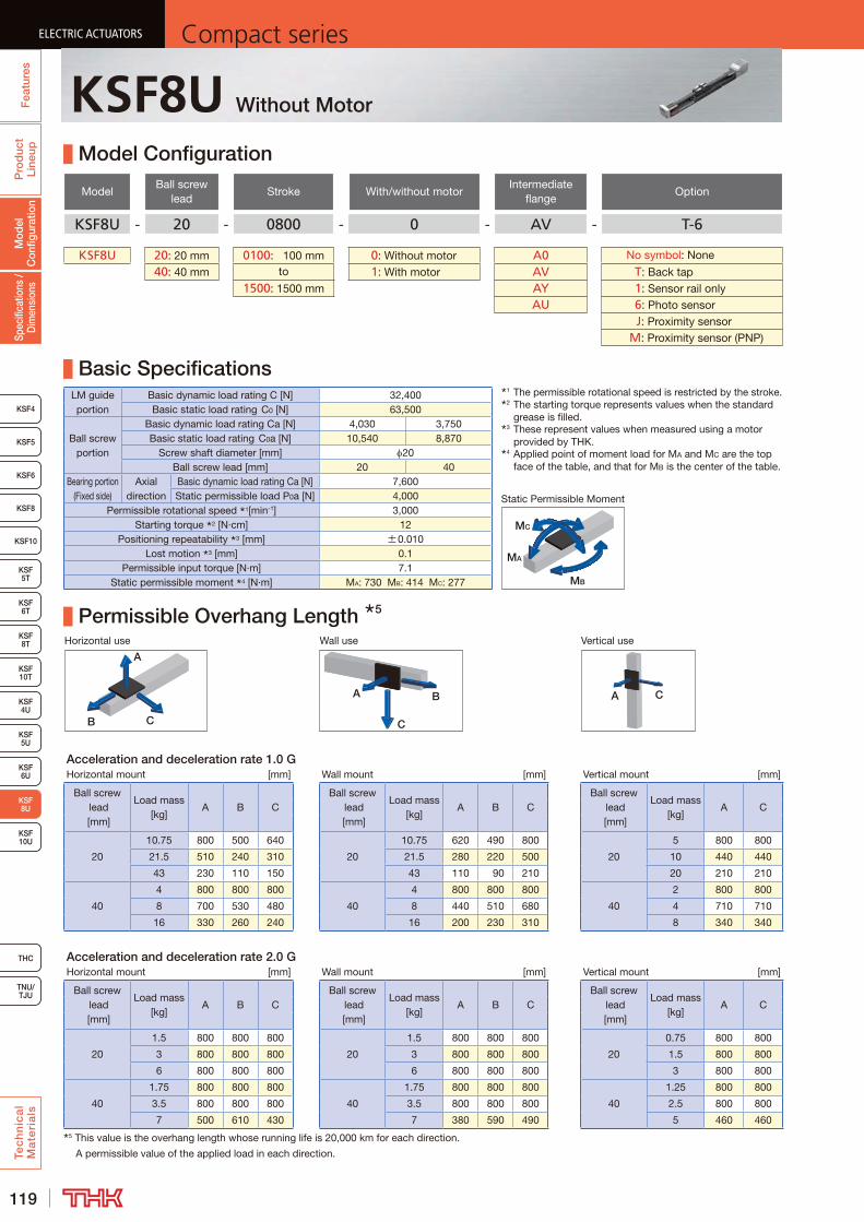
119
ELECTRIC ACTUATORS Compact seriesP
rod
uct
Line
upTe
ch
nic
al
Ma
teri
als
KSF8
KSF4
KSF 10T
KSF10
KSF 5T
KSF 6T
KSF 8T
KSF 10U
KSF 4U
KSF 6U
TNU/TJU
THC
Spec
ifica
tions
/ D
imen
sion
sM
odel
C
onfig
urat
ion
Fea
ture
sELECTRIC ACTUATORS Compact series
KSF5
KSF6
ELECTRIC ACTUATORS Compact series
KSF 8U
KSF 5U
ELECTRIC ACTUATORS Compact series
KSF8U Without Motor
Model Configuration
ModelBall screw
leadStroke With/without motor
Intermediate flange
Option
KSF8U - 20 - 0800 - 0 - AV - T-6
KSF8U 20: 20 mm 0100: 100 mm 0: Without motor A0 No symbol: None
40: 40 mm to 1: With motor AV T : Back tap1500: 1500 mm AY 1 : Sensor rail only
AU 6 : Photo sensor J : Proximity sensor M : Proximity sensor (PNP)
Basic SpecificationsLM guide portion
Basic dynamic load rating C [N] 32,400Basic static load rating C0 [N] 63,500
Ball screw portion
Basic dynamic load rating Ca [N] 4,030 3,750Basic static load rating C0a [N] 10,540 8,870
Screw shaft diameter [mm] 20Ball screw lead [mm] 20 40
Bearing portion (Fixed side)
Axial direction
Basic dynamic load rating Ca [N] 7,600Static permissible load P0a [N] 4,000
Permissible rotational speed 1[min-1] 3,000Starting torque 2 [N·cm] 12
Positioning repeatability 3 [mm] ±0.010Lost motion 3 [mm] 0.1
Permissible input torque [N·m] 7.1Static permissible moment 4 [N·m] MA: 730 MB: 414 MC: 277
Permissible Overhang Length 5
Horizontal use Wall use Vertical use
CB
A
A B
C
A C
Acceleration and deceleration rate 1.0 GHorizontal mount [mm] Wall mount [mm] Vertical mount [mm]
Ball screw lead [mm]
Load mass [kg]
A B CBall screw
lead [mm]
Load mass [kg]
A B CBall screw
lead [mm]
Load mass [kg]
A C
20
10.75 800 500 640
20
10.75 620 490 800
20
5 800 800
21.5 510 240 310 21.5 280 220 500 10 440 440
43 230 110 150 43 110 90 210 20 210 210
40
4 800 800 800
40
4 800 800 800
40
2 800 800
8 700 530 480 8 440 510 680 4 710 710
16 330 260 240 16 200 230 310 8 340 340
Acceleration and deceleration rate 2.0 GHorizontal mount [mm] Wall mount [mm] Vertical mount [mm]
Ball screw lead [mm]
Load mass [kg]
A B CBall screw
lead [mm]
Load mass [kg]
A B CBall screw
lead [mm]
Load mass [kg]
A C
20
1.5 800 800 800
20
1.5 800 800 800
20
0.75 800 800
3 800 800 800 3 800 800 800 1.5 800 800
6 800 800 800 6 800 800 800 3 800 800
40
1.75 800 800 800
40
1.75 800 800 800
40
1.25 800 800
3.5 800 800 800 3.5 800 800 800 2.5 800 800
7 500 610 430 7 380 590 490 5 460 4605 This value is the overhang length whose running life is 20,000 km for each direction.
A permissible value of the applied load in each direction.
MB
MA
MC
Static Permissible Moment
1 The permissible rotational speed is restricted by the stroke.2 The starting torque represents values when the standard
grease is filled.3 These represent values when measured using a motor
provided by THK.4 Applied point of moment load for MA and MC are the top
face of the table, and that for MB is the center of the table.

120
ELECTRIC ACTUATORSCompact series
Pro
duc
t Li
neup
Tec
hn
ica
l M
ate
ria
ls
THC
TNU/TJU
KSF8
KSF4
KSF 10T
KSF10
KSF 5T
KSF 6T
KSF 8T
KSF 10U
KSF 4U
KSF 6U
Spec
ifica
tions
/ D
imen
sion
sM
odel
C
onfig
urat
ion
Fea
ture
s
ELECTRIC ACTUATORSCompact series
KSF5
KSF6
ELECTRIC ACTUATORSCompact series
KSF 8U
KSF 5U
ELECTRIC ACTUATORSCompact series
KSF8U
Dimensions
Stroke [mm] (Stroke between mechanical stoppers)
100 (120)
200 (220)
300 (320)
400 (420)
500 (520)
600 (620)
700 (720)
800 (820)
900 (920)
1000 (1020)
1100 (1120)
1200 (1220)
1300 (1320)
1400 (1420)
1500 (1520)
Maximum speed 3 [mm/s]
Ball screw lead: 20 mm 1000 970 790 660 550 470 410 360 320Ball screw lead: 40 mm 2000 1940 1580 1320 1110 950 830 720 640
Dimensions [mm]
AL 478 578 678 778 878 978 1078 1178 1278 1378 1478 1578 1678 1778 1887G 85 135 85 135 85 135 85 135 85 135 85 135 85 135 85H 300 400 500 600 700 800 900 1000 1100 1200 1300 1400 1500 1600 1700Z 85 35 85 35 85 35 85 35 85 35 85 35 85 35 85F 200 400 400 600 600 800 800 1000 1000 1200 1200 1400 1400 1600 1600
Mounting pitch count N 1 1 2 2 3 3 4 4 5 5 6 6 7 7 8
Mounting hole countn 2 2 3 3 4 4 5 5 6 6 7 7 8 8 9n1 2 3 3 4 4 5 5 6 6 7 7 8 8 9 9
Weight [kg] 7.4 8.6 9.8 10.9 12.1 13.3 14.5 15.6 16.8 18.0 19.2 20.3 21.5 22.7 23.93 The maximum speed is the value restricted by the motor rotational speed (at 3000 min-1) or by the permissible rotational speed of the ball screw.
Detailed drawing of motor mounting part (when A0 is selected) 2 A-A cross section
Detailed Diagram: Elongated Hole
Detailed Diagram: Inner Block
1 Stroke up to mechanical stopper.2 See P.138 for intermediate flange dimensions.
A
A
B14
50H
7+
0.02
5 0
37
17
11
10
12h7
0 -0.0
18
31
44
3.5
2- 5H7 + 0.012 Depth 10 0
(Dowel pin hole)
30°
PCD60
4-M3 Depth 6 (Mouth C1)(Sensor dog mounting hole)
3.7
38±
0.02
(Dim
ensio
nal t
oler
ance
is
appl
icab
le to
5
only)
2 × n1 - M2.6 Depth 3.5 (same position as opposite side)(Sensor rail mounting holes)
1030°
Stroke120
200
(G)
100
4-M4 Depth 8(Intermediate flange mounting hole)
11
(R) (R)
5+
0.03
0 0
93
35 H
67.3
N × 200
Elongated hole Depth 55H7 + 0.012 Depth 5 (drilled through pilot hole) 0
(Dowel pin hole)
Z
G
(10) 1 (10) 1
(168)
4-M6 Depth 12(Inner block mounting holes)
From surface B2 × n- 6.6 through 11 counter bore Depth 6.3(Outer rail mounting hole)
70±0.02
(AL)
(90)
(Z)(n1-1) × 200 = F
200
589.
3
17
3252
46
31.2
16
80
10
2 (Sen
sor d
og
mou
ntin
g su
rface
)
1
193
1984
2-(R6)
(2)
(2)
84
(86.4)

121
ELECTRIC ACTUATORS Compact seriesP
rod
uct
Line
upTe
ch
nic
al
Ma
teri
als
KSF8
KSF4
KSF 10T
KSF10
KSF 5T
KSF 6T
KSF 8T
KSF 10U
KSF 4U
KSF 6U
TNU/TJU
THC
Spec
ifica
tions
/ D
imen
sion
sM
odel
C
onfig
urat
ion
Fea
ture
sELECTRIC ACTUATORS Compact series
KSF5
KSF6
ELECTRIC ACTUATORS Compact series
KSF 8U
KSF 5U
ELECTRIC ACTUATORS Compact series
KSF8RU Without Motor
Model Configuration
ModelBall screw
leadStroke
With/without motor
Motor mounting plate
Motor shaft diameter
Motor shaft fixing method
Option
KSF8RU - 20 - 0800 - 0 - WV - 14 M - MR-T
KSF8RU 20: 20 mm 0100: 100 mm 0: Without motor WV 14: 14 mm M: Friction tightening MR : Motor right wrap40: 40 mm to 1: With motor WY ML : Motor left wrap
1500: 1500 mm MD : Motor down wrap T : Back tap 1 : Sensor rail only 6 : Photo sensor J : Proximity sensor M : Proximity sensor (PNP)
Basic SpecificationsLM guide portion
Basic dynamic load rating C [N] 32,400Basic static load rating C0 [N] 63,500
Ball screw portion
Basic dynamic load rating Ca [N] 4,030 3,750Basic static load rating C0a [N] 10,540 8,870
Screw shaft diameter [mm] 20Ball screw lead [mm] 20 40
Bearing portion (Fixed side)
Axial direction
Basic dynamic load rating Ca [N] 7,600Static permissible load P0a [N] 4,000
Permissible rotational speed 1[min-1] 3,000Starting torque 2 [N·cm] 12
Positioning repeatability 3 [mm] ±0.010Lost motion 3 [mm] 0.1
Permissible input torque [N·m] 4.5Static permissible moment 4 [N·m] MA: 730 MB: 414 MC: 277
Permissible Overhang Length 5
Horizontal use Wall use Vertical use
CB
A
A B
C
A C
Acceleration and deceleration rate 1.0 GHorizontal mount [mm] Wall mount [mm] Vertical mount [mm]
Ball screw lead [mm]
Load mass [kg]
A B CBall screw
lead [mm]
Load mass [kg]
A B CBall screw
lead [mm]
Load mass [kg]
A C
20
10.25 800 520 670
20
10.25 630 500 800
20
5 800 800
20.5 540 250 330 20.5 290 230 510 10 440 440
41 240 110 160 41 120 90 220 20 210 210
40
4 800 800 800
40
4 800 800 800
40
2 800 800
8 700 530 480 8 440 510 680 4 710 710
16 330 260 240 16 200 230 310 8 340 340
Acceleration and deceleration rate 2.0 GHorizontal mount [mm] Wall mount [mm] Vertical mount [mm]
Ball screw lead [mm]
Load mass [kg]
A B CBall screw
lead [mm]
Load mass [kg]
A B CBall screw
lead [mm]
Load mass [kg]
A C
20
1.5 800 800 800
20
1.5 800 800 800
20
0.75 800 800
3 800 800 800 3 800 800 800 1.5 800 800
6 800 800 800 6 800 800 800 3 800 800
40
1.75 800 800 800
40
1.75 800 800 800
40
1.25 800 800
3.5 800 800 800 3.5 800 800 800 2.5 800 800
7 500 610 430 7 380 590 490 5 460 4605 This value is the overhang length whose running life is 20,000 km for each direction.
A permissible value of the applied load in each direction.
MB
MA
MC
Static Permissible Moment
1 The permissible rotational speed is restricted by the stroke.2 The starting torque represents values when the standard
grease is filled.3 These represent values when measured using a motor
provided by THK.4 Applied point of moment load for MA and MC are the top
face of the table, and that for MB is the center of the table.
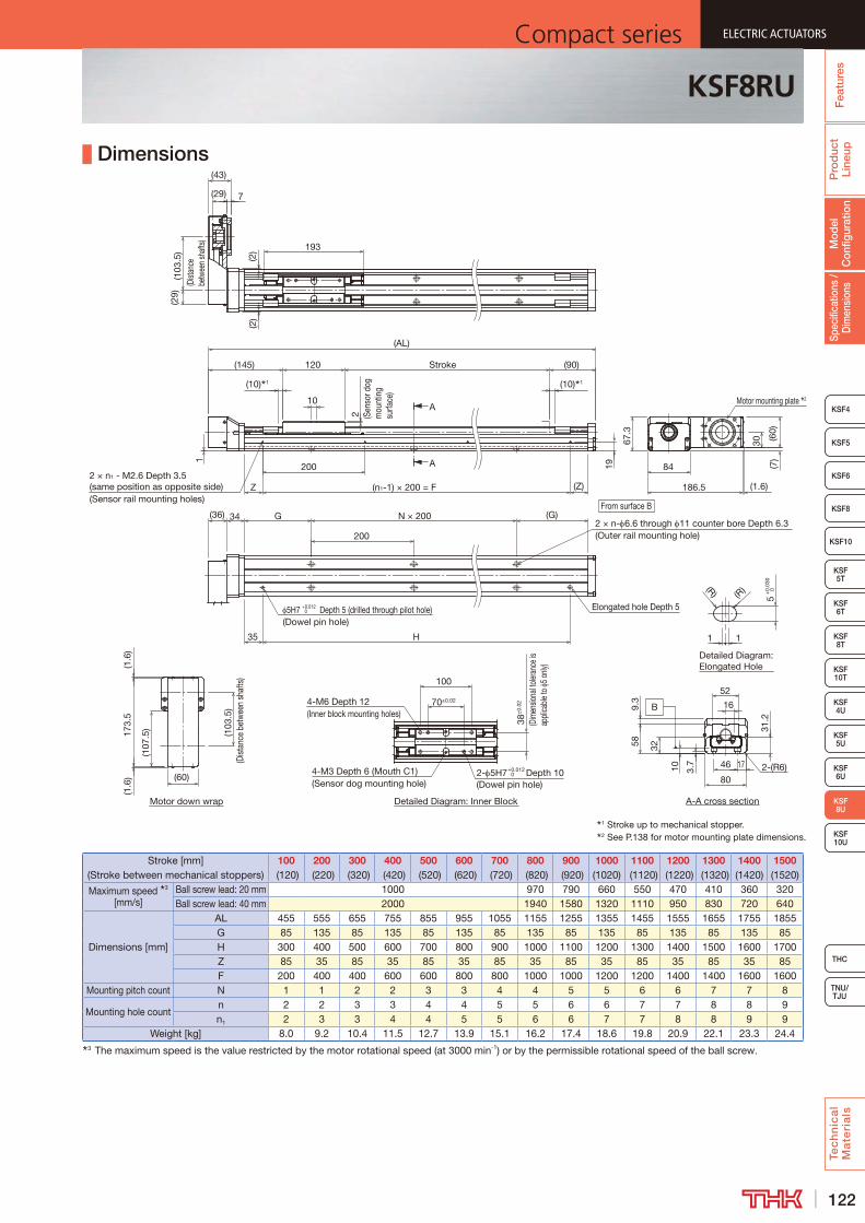
122
ELECTRIC ACTUATORSCompact series
Pro
duc
t Li
neup
Tec
hn
ica
l M
ate
ria
ls
THC
TNU/TJU
KSF8
KSF4
KSF 10T
KSF10
KSF 5T
KSF 6T
KSF 8T
KSF 10U
KSF 4U
KSF 6U
Spec
ifica
tions
/ D
imen
sion
sM
odel
C
onfig
urat
ion
Fea
ture
s
ELECTRIC ACTUATORSCompact series
KSF5
KSF6
ELECTRIC ACTUATORSCompact series
KSF 8U
KSF 5U
ELECTRIC ACTUATORSCompact series
KSF8RU
Dimensions
Stroke [mm] (Stroke between mechanical stoppers)
100 (120)
200 (220)
300 (320)
400 (420)
500 (520)
600 (620)
700 (720)
800 (820)
900 (920)
1000 (1020)
1100 (1120)
1200 (1220)
1300 (1320)
1400 (1420)
1500 (1520)
Maximum speed 3 [mm/s]
Ball screw lead: 20 mm 1000 970 790 660 550 470 410 360 320Ball screw lead: 40 mm 2000 1940 1580 1320 1110 950 830 720 640
Dimensions [mm]
AL 455 555 655 755 855 955 1055 1155 1255 1355 1455 1555 1655 1755 1855G 85 135 85 135 85 135 85 135 85 135 85 135 85 135 85H 300 400 500 600 700 800 900 1000 1100 1200 1300 1400 1500 1600 1700Z 85 35 85 35 85 35 85 35 85 35 85 35 85 35 85F 200 400 400 600 600 800 800 1000 1000 1200 1200 1400 1400 1600 1600
Mounting pitch count N 1 1 2 2 3 3 4 4 5 5 6 6 7 7 8
Mounting hole countn 2 2 3 3 4 4 5 5 6 6 7 7 8 8 9n1 2 3 3 4 4 5 5 6 6 7 7 8 8 9 9
Weight [kg] 8.0 9.2 10.4 11.5 12.7 13.9 15.1 16.2 17.4 18.6 19.8 20.9 22.1 23.3 24.43 The maximum speed is the value restricted by the motor rotational speed (at 3000 min-1) or by the permissible rotational speed of the ball screw.
1 Stroke up to mechanical stopper.2 See P.138 for motor mounting plate dimensions.
Detailed Diagram: Elongated Hole
Detailed Diagram: Inner Block
A
A
Motor down wrap A-A cross section
B
2- 5H7+0.012 0 Depth 10
(Dowel pin hole)4-M3 Depth 6 (Mouth C1)(Sensor dog mounting hole)
38±
0.02
100
11
(R) (R)
5+
0.03
0 0
4-M6 Depth 12(Inner block mounting holes)
70±0.02
120
7
19
1
193
2 (Sen
sor d
og
mou
ntin
g su
rface
)10
Stroke
2 × n1 - M2.6 Depth 3.5 (same position as opposite side)(Sensor rail mounting holes)
200
(n1-1) × 200 = F (Z)
(90)
(10) 1
Z
(103
.5)
(Dist
ance
bet
wee
n sh
afts
)
(1.6
)
(107
.5)
173.
5
(AL)
200
(G)
35 H
N × 200
Elongated hole Depth 55H7 +0.012 0 Depth 5 (drilled through pilot hole)
(Dowel pin hole)
GFrom surface B
2 × n- 6.6 through 11 counter bore Depth 6.3(Outer rail mounting hole)
(36) 34
(1.6
)
(2)
(2)
(29)
(43)
(145)
84
186.5 (1.6)
(7)
30 (60)
67.3
Motor mounting plate 2
(29)
(103
.5)
(Dist
ance
be
twee
n sh
afts)
3.7
10
589.
3
17
32
52
4631
.2
16
802-(R6)
(60)
(10) 1
(Dim
ensio
nal to
leran
ce is
ap
plica
ble to
5 o
nly)

123
ELECTRIC ACTUATORS Compact seriesP
rod
uct
Line
upTe
ch
nic
al
Ma
teri
als
KSF8
KSF4
KSF 10T
KSF10
KSF 5T
KSF 6T
KSF 8T
KSF 4U
KSF 5U
KSF 6U
KSF 8U
TNU/TJU
THC
Spec
ifica
tions
/ D
imen
sion
sM
odel
C
onfig
urat
ion
Fea
ture
sELECTRIC ACTUATORS Compact series
KSF5
KSF6
ELECTRIC ACTUATORS Compact series
KSF 10U
ELECTRIC ACTUATORS Compact series
KSF10U Without Motor
Model Configuration
ModelBall screw
leadStroke With/without motor
Intermediate flange
Option
KSF10U - 25 - 0800 - 0 - AZ - T-6
KSF10U 25: 25 mm 0100: 100 mm 0: Without motor A0 No symbol: None
50: 50 mm to 1: With motor AZ T : Back tap1500: 1500 mm A5 1 : Sensor rail only
A6 6 : Photo sensor J : Proximity sensor M : Proximity sensor (PNP)
Basic SpecificationsLM guide portion
Basic dynamic load rating C [N] 58,500Basic static load rating C0 [N] 103,700
Ball screw portion
Basic dynamic load rating Ca [N] 6,650 4,150Basic static load rating C0a [N] 21,050 11,170
Screw shaft diameter [mm] 25Ball screw lead [mm] 25 50
Bearing portion (Fixed side)
Axial direction
Basic dynamic load rating Ca [N] 13,700Static permissible load P0a [N] 5,830
Permissible rotational speed 1[min-1] 3,000Starting torque 2 [N·cm] 12 16
Positioning repeatability 3 [mm] ±0.010Lost motion 3 [mm] 0.1
Permissible input torque [N·m] 15.5Static permissible moment 4 [N·m] MA: 1,259 MB: 775 MC: 504
Permissible Overhang Length 5
Horizontal use Wall use Vertical use
CB
A
A B
C
A C
Acceleration and deceleration rate 1.0 GHorizontal mount [mm] Wall mount [mm] Vertical mount [mm]
Ball screw lead [mm]
Load mass [kg]
A B CBall screw
lead [mm]
Load mass [kg]
A B CBall screw
lead [mm]
Load mass [kg]
A C
25
15 1000 760 900
25
15 860 740 1000
25
6.25 1000 1000
30 680 370 440 30 400 350 650 12.5 730 730
60 320 170 220 60 170 150 290 25 350 350
50
4.25 1000 1000 1000
50
4.25 1000 1000 1000
50
2.25 1000 1000
8.5 1000 1000 840 8.5 810 1000 1000 4.5 1000 1000
17 600 530 420 17 380 500 570 9 960 960
Acceleration and deceleration rate 1.5 GHorizontal mount [mm] Wall mount [mm] Vertical mount [mm]
Ball screw lead [mm]
Load mass [kg]
A B CBall screw
lead [mm]
Load mass [kg]
A B CBall screw
lead [mm]
Load mass [kg]
A C
25
6.5 1000 1000 1000
25
6.5 1000 1000 1000
25
3.25 1000 1000
13 1000 880 910 13 870 860 1000 6.5 1000 1000
26 600 430 460 26 410 400 580 13 650 650
50
2 1000 1000 1000
50
2 1000 1000 1000
50
1.25 1000 1000
4 1000 1000 1000 4 1000 1000 1000 2.5 1000 1000
8 1000 1000 780 8 730 1000 990 5 970 9705 This value is the overhang length whose running life is 20,000 km for each direction.
A permissible value of the applied load in each direction.
MB
MA
MC
Static Permissible Moment
1 The permissible rotational speed is restricted by the stroke.2 The starting torque represents values when the standard
grease is filled.3 These represent values when measured using a motor
provided by THK.4 Applied point of moment load for MA and MC are the top
face of the table, and that for MB is the center of the table.
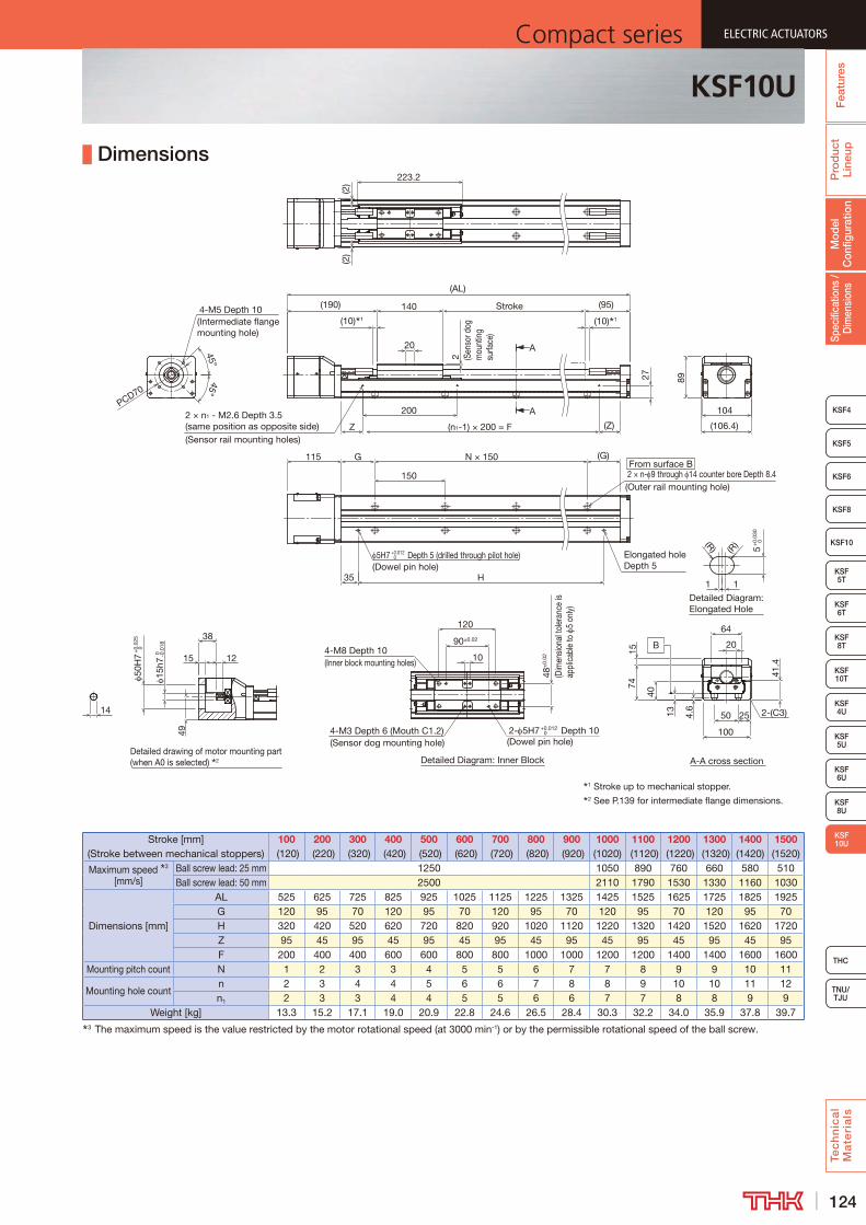
124
ELECTRIC ACTUATORSCompact series
Pro
duc
t Li
neup
Tec
hn
ica
l M
ate
ria
ls
THC
TNU/TJU
KSF8
KSF4
KSF 10T
KSF10
KSF 5T
KSF 6T
KSF 8T
KSF 4U
KSF 5U
KSF 6U
KSF 8U
Spec
ifica
tions
/ D
imen
sion
sM
odel
C
onfig
urat
ion
Fea
ture
s
ELECTRIC ACTUATORSCompact series
KSF5
KSF6
ELECTRIC ACTUATORSCompact series
KSF 10U
ELECTRIC ACTUATORSCompact series
KSF10U
Dimensions
Stroke [mm] (Stroke between mechanical stoppers)
100 (120)
200 (220)
300 (320)
400 (420)
500 (520)
600 (620)
700 (720)
800 (820)
900 (920)
1000 (1020)
1100 (1120)
1200 (1220)
1300 (1320)
1400 (1420)
1500 (1520)
Maximum speed 3 [mm/s]
Ball screw lead: 25 mm 1250 1050 890 760 660 580 510Ball screw lead: 50 mm 2500 2110 1790 1530 1330 1160 1030
Dimensions [mm]
AL 525 625 725 825 925 1025 1125 1225 1325 1425 1525 1625 1725 1825 1925G 120 95 70 120 95 70 120 95 70 120 95 70 120 95 70H 320 420 520 620 720 820 920 1020 1120 1220 1320 1420 1520 1620 1720Z 95 45 95 45 95 45 95 45 95 45 95 45 95 45 95F 200 400 400 600 600 800 800 1000 1000 1200 1200 1400 1400 1600 1600
Mounting pitch count N 1 2 3 3 4 5 5 6 7 7 8 9 9 10 11
Mounting hole countn 2 3 4 4 5 6 6 7 8 8 9 10 10 11 12n1 2 3 3 4 4 5 5 6 6 7 7 8 8 9 9
Weight [kg] 13.3 15.2 17.1 19.0 20.9 22.8 24.6 26.5 28.4 30.3 32.2 34.0 35.9 37.8 39.73 The maximum speed is the value restricted by the motor rotational speed (at 3000 min-1) or by the permissible rotational speed of the ball screw.
1 Stroke up to mechanical stopper.2 See P.139 for intermediate flange dimensions.
Detailed Diagram: Elongated Hole
A-A cross sectionDetailed drawing of motor mounting part (when A0 is selected) 2 Detailed Diagram: Inner Block
A
A
B
2 (Sen
sor d
og
mou
ntin
g su
rface
)
10
Stroke
2- 5H7+0.012 0 Depth 10
(Dowel pin hole)
140
(10) 1
(95)(190)
(AL)
20
4-M5 Depth 10(Intermediate flange mounting hole)
N × 150
(R) (R) 5+
0.03
0 0
11
From surface B2 × n- 9 through 14 counter bore Depth 8.4(Outer rail mounting hole)
5H7 +0.012 Depth 5 (drilled through pilot hole)(Dowel pin hole)
Elongated hole Depth 5
H
(G)115 G
150
35
45°
PCD70
(10) 1
4-M8 Depth 10(Inner block mounting holes)
90±0.02
120
48±
0.02
(Dim
ensio
nal t
oler
ance
is
appl
icab
le to
5
only)
4-M3 Depth 6 (Mouth C1.2)(Sensor dog mounting hole)
50H
7+
0.02
5 0
15h7
0 -0.0
18
38
13 4.6
4015
41.4
20
25
1574
100
50
12
49223.2
(2)
(2)
14 2-(C3)
64
27
200
(n1-1) × 200 = FZ (Z)2 × n1 - M2.6 Depth 3.5 (same position as opposite side)(Sensor rail mounting holes)
104
89
(106.4)
45°
0

125
ELECTRIC ACTUATORS Compact seriesP
rod
uct
Line
upTe
ch
nic
al
Ma
teri
als
KSF8
KSF4
KSF 10T
KSF10
KSF 5T
KSF 6T
KSF 8T
KSF 4U
KSF 5U
KSF 6U
KSF 8U
TNU/TJU
THC
Spec
ifica
tions
/ D
imen
sion
sM
odel
C
onfig
urat
ion
Fea
ture
sELECTRIC ACTUATORS Compact series
KSF5
KSF6
ELECTRIC ACTUATORS Compact series
KSF 10U
ELECTRIC ACTUATORS Compact series
KSF10RU Without Motor
Model Configuration
ModelBall screw
leadStroke
With/without motor
Motor mounting plate
Motor shaft diameter
Motor shaft fixing method
Option
KSF10RU - 25 - 0800 - 0 - WZ - 19 M - MR-T
KSF10RU 25: 25 mm 0100: 100 mm 0: Without motor WZ 16: 16 mm M: Friction tightening MR : Motor right wrap50: 50 mm to 1: With motor W5 19: 19 mm ML : Motor left wrap
1500: 1500 mm MD : Motor down wrap T : Back tap 1 : Sensor rail only 6 : Photo sensor J : Proximity sensor M : Proximity sensor (PNP)
Basic SpecificationsLM guide portion
Basic dynamic load rating C [N] 58,500Basic static load rating C0 [N] 103,700
Ball screw portion
Basic dynamic load rating Ca [N] 6,650 4,150Basic static load rating C0a [N] 21,050 11,170
Screw shaft diameter [mm] 25Ball screw lead [mm] 25 50
Bearing portion (Fixed side)
Axial direction
Basic dynamic load rating Ca [N] 13,700Static permissible load P0a [N] 5,830
Permissible rotational speed 1[min-1] 3,000Starting torque 2 [N·cm] 12 16
Positioning repeatability 3 [mm] ±0.010Lost motion 3 [mm] 0.1
Permissible input torque [N·m] 8.5Static permissible moment 4 [N·m] MA: 1,259 MB: 775 MC: 504
Permissible Overhang Length 5
Horizontal use Wall use Vertical use
CB
A
A B
C
A C
Acceleration and deceleration rate 1.0 GHorizontal mount [mm] Wall mount [mm] Vertical mount [mm]
Ball screw lead [mm]
Load mass [kg]
A B CBall screw
lead [mm]
Load mass [kg]
A B CBall screw
lead [mm]
Load mass [kg]
A C
25
9.5 1000 1000 1000
25
9.5 1000 1000 1000
25
4.75 1000 1000
19 1000 600 700 19 670 570 1000 9.5 970 970
38 530 290 350 38 310 260 500 19 470 470
50
3 1000 1000 1000
50
3 1000 1000 1000
50
1.75 1000 1000
6 1000 1000 1000 6 1000 1000 1000 3.5 1000 1000
12 870 760 600 12 560 730 840 7 770 770
Acceleration and deceleration rate 1.5 GHorizontal mount [mm] Wall mount [mm] Vertical mount [mm]
Ball screw lead [mm]
Load mass [kg]
A B CBall screw
lead [mm]
Load mass [kg]
A B CBall screw
lead [mm]
Load mass [kg]
A C
25
2 1000 1000 1000
25
2 1000 1000 1000
25
0.75 1000 1000
4 1000 1000 1000 4 1000 1000 1000 1.5 1000 1000
8 1000 1000 1000 8 1000 1000 1000 3 1000 1000
50
1 1000 1000 1000
50
1 1000 1000 1000
50
0.75 1000 1000
2 1000 1000 1000 2 1000 1000 1000 1.5 1000 1000
4 1000 1000 1000 4 1000 1000 1000 3 1000 10005 This value is the overhang length whose running life is 20,000 km for each direction.
A permissible value of the applied load in each direction.
MB
MA
MC
Static Permissible Moment
1 The permissible rotational speed is restricted by the stroke.2 The starting torque represents values when the standard
grease is filled.3 These represent values when measured using a motor
provided by THK.4 Applied point of moment load for MA and MC are the top
face of the table, and that for MB is the center of the table.
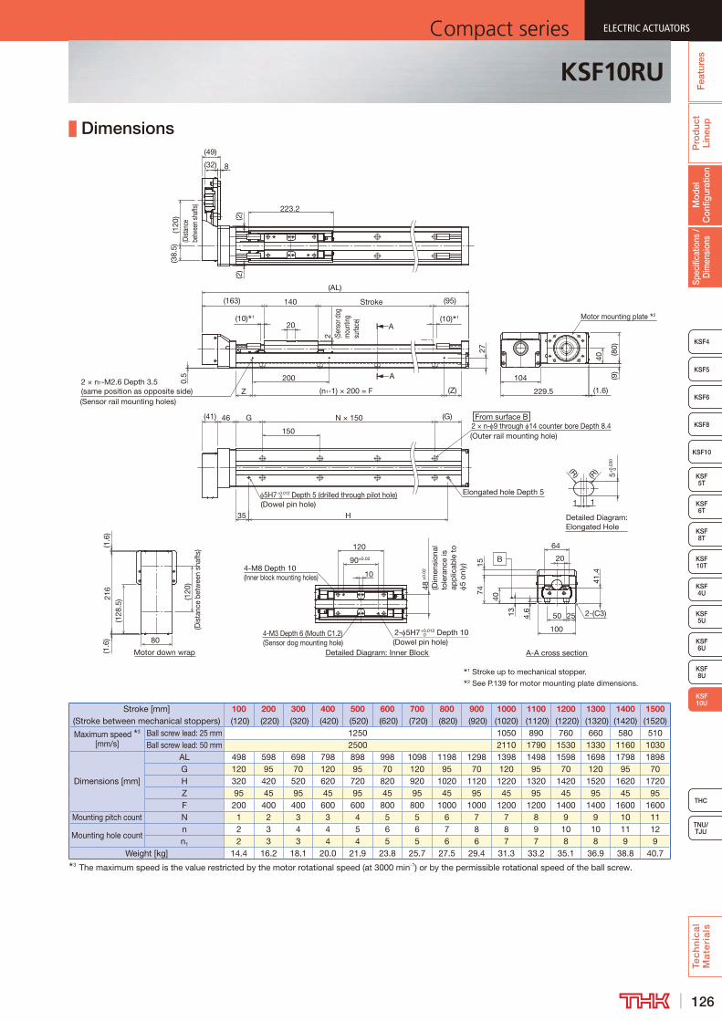
126
ELECTRIC ACTUATORSCompact series
Pro
duc
t Li
neup
Tec
hn
ica
l M
ate
ria
ls
THC
TNU/TJU
KSF8
KSF4
KSF 10T
KSF10
KSF 5T
KSF 6T
KSF 8T
KSF 4U
KSF 5U
KSF 6U
KSF 8U
Spec
ifica
tions
/ D
imen
sion
sM
odel
C
onfig
urat
ion
Fea
ture
s
ELECTRIC ACTUATORSCompact series
KSF5
KSF6
ELECTRIC ACTUATORSCompact series
KSF 10U
ELECTRIC ACTUATORSCompact series
KSF10RU
Dimensions
Stroke [mm] (Stroke between mechanical stoppers)
100 (120)
200 (220)
300 (320)
400 (420)
500 (520)
600 (620)
700 (720)
800 (820)
900 (920)
1000 (1020)
1100 (1120)
1200 (1220)
1300 (1320)
1400 (1420)
1500 (1520)
Maximum speed 3 [mm/s]
Ball screw lead: 25 mm 1250 1050 890 760 660 580 510Ball screw lead: 50 mm 2500 2110 1790 1530 1330 1160 1030
Dimensions [mm]
AL 498 598 698 798 898 998 1098 1198 1298 1398 1498 1598 1698 1798 1898G 120 95 70 120 95 70 120 95 70 120 95 70 120 95 70H 320 420 520 620 720 820 920 1020 1120 1220 1320 1420 1520 1620 1720Z 95 45 95 45 95 45 95 45 95 45 95 45 95 45 95F 200 400 400 600 600 800 800 1000 1000 1200 1200 1400 1400 1600 1600
Mounting pitch count N 1 2 3 3 4 5 5 6 7 7 8 9 9 10 11
Mounting hole countn 2 3 4 4 5 6 6 7 8 8 9 10 10 11 12n1 2 3 3 4 4 5 5 6 6 7 7 8 8 9 9
Weight [kg] 14.4 16.2 18.1 20.0 21.9 23.8 25.7 27.5 29.4 31.3 33.2 35.1 36.9 38.8 40.73 The maximum speed is the value restricted by the motor rotational speed (at 3000 min-1) or by the permissible rotational speed of the ball screw.
2 × n- 9 through 14 counter bore Depth 8.4
Motor down wrap
1 Stroke up to mechanical stopper.2 See P.139 for motor mounting plate dimensions.
Detailed Diagram: Elongated Hole
Detailed Diagram: Inner Block
A
A
A-A cross section
B
4-M3 Depth 6 (Mouth C1.2)(Sensor dog mounting hole)
48±
0.02
(Dim
ensi
onal
to
lera
nce
is
app
licab
le t
o 5
only
)
120
90±0.02
4-M8 Depth 10(Inner block mounting holes)
1 1
5+0.
030
0
(R)(R)
2- 5H7+0.012 0 Depth 10
(Dowel pin hole)
10
(120
)(D
ista
nce
betw
een
shaf
ts)
(128
.5)21
6(1
.6)
(1.6
)
80
2 (Sen
sor d
og
mou
nting
su
rface
)
Stroke140
(10) 1
(95)
20
5H7+0.012 0 Depth 5 (drilled through pilot hole)
(Dowel pin hole)
Elongated hole Depth 5
H35
(10) 1
223.2
(2)
(2)
150
G (G) From surface B
(Outer rail mounting hole)
N × 15046(41)
27
200
(n1-1) × 200 = FZ (Z)2 × n1-M2.6 Depth 3.5 (same position as opposite side)(Sensor rail mounting holes)
(163)
(AL)
104
229.5 (1.6)
40
(9)
(80)
8(32)
(49)
(38.
5)(1
20)
(Dist
ance
be
twee
n sh
afts)
Motor mounting plate 2
0.5
64
2-(C3)50
100
7415
25
20
41.4
40
4.613
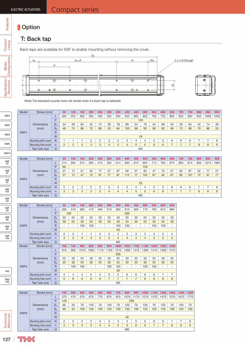
127
ELECTRIC ACTUATORS Compact series
KSF8
KSF4
KSF5
KSF6
KSF 10T
KSF10
KSF 5T
KSF 6T
KSF 8T
KSF 10U
KSF 4U
KSF 5U
KSF 6U
KSF 8U
TNU/TJU
THC
Fea
ture
sP
rod
uct
Line
upM
odel
C
onfig
urat
ion
Spec
ifica
tions
/ D
imen
sion
sTe
ch
nic
al
Ma
teri
als
Option
T: Back tap
R (G2)
W
N x P
P
G1
(L)
2 x n-Q through
Note) The standard counter bore will remain even if a back tap is selected.
Model Stroke [mm] 50 100 150 200 250 300 350 400 450 500 550 600 650 700 750 800 850 900
KSF4
Dimensions [mm]
L 202 252 302 352 402 452 502 552 602 652 702 752 802 852 902 952 1002 1052P 120G1 34 59 84 42 74 39 78 89 54 79 44 69 34 59 84 42 74 39G2 48 73 98 70 88 53 64 103 68 93 58 83 48 73 98 70 88 53R -W 18
Mounting pitch count N 1 1 1 2 2 3 3 3 4 4 5 5 6 6 6 7 7 8Mounting hole count n 2 2 2 3 3 4 4 4 5 5 6 6 7 7 7 8 8 9
Tap hole size Q M4
Model Stroke [mm] 50 100 150 200 250 300 350 400 450 500 550 600 650 700 750 800 850 900
KSF5
Dimensions [mm]
L 214 264 314 364 414 464 514 564 614 664 714 764 814 864 914 964 1014 1064P 80 120G1 27 12 27 52 77 27 67 92 57 82 47 72 27 62 87 52 77 27G2 27 12 47 72 97 77 87 112 77 102 67 92 67 82 107 72 97 77R -W 25
Mounting pitch count N 2 2 2 2 2 3 3 3 4 4 5 5 6 6 6 7 7 8Mounting hole count n 3 3 3 3 3 4 4 4 5 5 6 6 7 7 7 8 8 9
Tap hole size Q M5
Model Stroke [mm] 50 100 150 200 250 300 350 400 450 500 550 600 650
KSF6
Dimensions [mm]
L 260 310 360 410 460 510 560 610 660 710 760 810 860P 100 200G1 30 55 30 55 30 55 30 55 30 55 30 55 30G2 30 55 30 55 30 55 30 55 30 55 30 55 30R - - 100 100 - - 100 100 - - 100 100 -W 30
Mounting pitch count N 2 2 1 1 2 2 2 2 3 3 3 3 4Mounting hole count n 3 3 3 3 3 3 4 4 4 4 5 5 5
Tap hole size Q M5Model Stroke [mm] 700 750 800 850 900 950 1000 1050 1100 1150 1200 1250 1300
KSF6
Dimensions [mm]
L 910 960 1010 1060 1110 1160 1210 1260 1310 1360 1410 1460 1510P 200G1 55 30 55 30 55 30 55 30 55 30 55 30 55G2 55 30 55 30 55 30 55 30 55 30 55 30 55R - 100 100 - - 100 100 - - 100 100 - -W 30
Mounting pitch count N 4 4 4 5 5 5 5 6 6 6 6 7 7Mounting hole count n 5 6 6 6 6 7 7 7 7 8 8 8 8
Tap hole size Q M5
Model Stroke [mm] 100 200 300 400 500 600 700 800 900 1000 1100 1200 1300 1400 1500
KSF8
Dimensions [mm]
L 370 470 570 670 770 870 970 1070 1170 1270 1370 1470 1570 1670 1770P 120 200G1 65 25 70 120 70 120 70 120 70 120 70 120 70 120 70G2 65 45 100 150 100 150 100 150 100 150 100 150 100 150 100R -W 46
Mounting pitch count N 2 2 2 2 3 3 4 4 5 5 6 6 7 7 8Mounting hole count n 3 3 3 3 4 4 5 5 6 6 7 7 8 8 9
Tap hole size Q M6

128
ELECTRIC ACTUATORSCompact series
THC
TNU/TJU
KSF8
KSF4
KSF5
KSF6
KSF 10T
KSF10
KSF 5T
KSF 6T
KSF 8T
KSF 10U
KSF 4U
KSF 5U
KSF 6U
KSF 8U
Fea
ture
sP
rod
uct
Line
upM
odel
C
onfig
urat
ion
Spec
ifica
tions
/ D
imen
sion
sTe
ch
nic
al
Ma
teri
als
R (G2)
W
N x P
P
G1
(L)
2 x n-Q through
Note) The standard counter bore will remain even if a back tap is selected.
Model Stroke [mm] 100 200 300 400 500 600 700 800 900 1000 1100 1200 1300 1400 1500
KSF10
Dimensions [mm]
L 390 490 590 690 790 890 990 1090 1190 1290 1390 1490 1590 1690 1790
P 150
G1 45 80 55 105 80 55 105 80 55 105 80 55 105 80 55
G2 45 110 85 135 110 85 135 110 85 135 110 85 135 110 85
R -
W 50
Mounting pitch count N 2 2 3 3 4 5 5 6 7 7 8 9 9 10 11
Mounting hole count n 3 3 4 4 5 6 6 7 8 8 9 10 10 11 12
Tap hole size Q M8
Option
□: Sensors
Note 1) Types without motor will be shipped with the sensor and the sensor dog.Note 2) If proximity sensors are placed too close to each other, they may not work properly. In this case, the customer must provide sensors with
variant frequencies. (For specifications, contact each manufacturer.)
Note 3) Mount two sensor dogs or sensor rails for 50 mm strokes.
Description Model Accessory 1 Symbol
With sensor rail 2 - Mounting screws, sensor rail 1
Photo sensor 3[3 pieces] EE-SX674 (Omron Corp.)Mounting screw, nut, mounting plate (× 3),
connector (EE-1001, × 3), sensor dog, sensor rail6
Sensor N.O. contact [× 1] GX-F12A (Panasonic Industrial Devices SUNX Co., Ltd.)Mounting screws, nuts, sensor dog, sensor rail J
N.C. contact [x 2] GX-F12B (Panasonic Industrial Devices SUNX Co., Ltd.)
Sensors N.O. contact [x 1] (PNP output) GX-F12A-P (Panasonic Industrial Devices SUNX Co., Ltd.)Mounting screws, nuts, sensor dog, sensor rail M
N.C. contact [x 2] (PNP output) GX-F12B-P (Panasonic Industrial Devices SUNX Co., Ltd.)
N.O. contact: Normally open contact point
N.C. contact: Normally closed contact point
Sensors marked with a symbol “M”, if combined with our controller, cannot be used as a home position sensor.1 Sensor rails are included for Top Cover and Open Cover specification types only.2 Selectable only for Top Cover and Open Cover specification types.3 The photo sensors can be switched between ON when lit and ON when unlit.
KSF4 or 5
KSF6, 8 or 10Sensor dog
Sensor dogFor motor wrap type, sensors cannot be mounted on the motor side within the range of interference with the motor
The range of interference with the motor
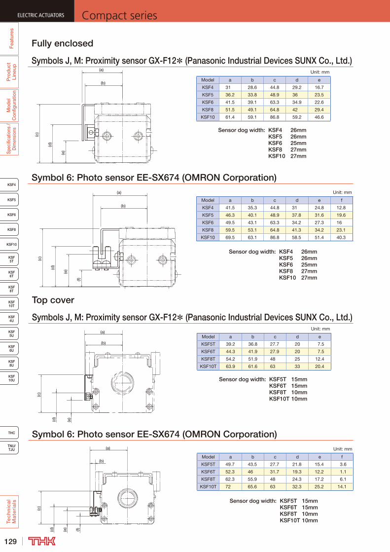
129
ELECTRIC ACTUATORS Compact series
KSF8
KSF4
KSF5
KSF6
KSF 10T
KSF10
KSF 5T
KSF 6T
KSF 8T
KSF 10U
KSF 4U
KSF 5U
KSF 6U
KSF 8U
TNU/TJU
THC
Fea
ture
sP
rod
uct
Line
upM
odel
C
onfig
urat
ion
Spec
ifica
tions
/ D
imen
sion
sTe
ch
nic
al
Ma
teri
als
Fully enclosed
Symbols J, M: Proximity sensor GX-F12* (Panasonic Industrial Devices SUNX Co., Ltd.)
Top cover
Symbols J, M: Proximity sensor GX-F12* (Panasonic Industrial Devices SUNX Co., Ltd.)
(a)
(b)
(c)
(d)
(e)
Symbol 6: Photo sensor EE-SX674 (OMRON Corporation)
Symbol 6: Photo sensor EE-SX674 (OMRON Corporation)
Unit: mm
Model a b c d e
KSF4 31 28.6 44.8 29.2 16.7
KSF5 36.2 33.8 48.9 36 23.5
KSF6 41.5 39.1 63.3 34.9 22.6
KSF8 51.5 49.1 64.8 42 29.4
KSF10 61.4 59.1 86.8 59.2 46.6
Unit: mm
Model a b c d e
KSF5T 39.2 36.8 27.7 20 7.5
KSF6T 44.3 41.9 27.9 20 7.5
KSF8T 54.2 51.9 48 25 12.4
KSF10T 63.9 61.6 63 33 20.4
(e)
(c)
(a)
(d)
(f)
(b)
Unit: mm
Model a b c d e f
KSF4 41.5 35.3 44.8 31 24.8 12.8
KSF5 46.3 40.1 48.9 37.8 31.6 19.6
KSF6 49.5 43.1 63.3 34.2 27.3 16
KSF8 59.5 53.1 64.8 41.3 34.2 23.1
KSF10 69.5 63.1 86.8 58.5 51.4 40.3
Unit: mm
Model a b c d e f
KSF5T 49.7 43.5 27.7 21.8 15.4 3.6
KSF6T 52.3 46 31.7 19.3 12.2 1.1
KSF8T 62.3 55.9 48 24.3 17.2 6.1
KSF10T 72 65.6 63 32.3 25.2 14.1
Sensor dog width: KSF4 26mm KSF5 26mm KSF6 25mm KSF8 27mm KSF10 27mm
Sensor dog width: KSF5T 15mm KSF6T 15mm KSF8T 10mm KSF10T 10mm
Sensor dog width: KSF4 26mm KSF5 26mm KSF6 25mm KSF8 27mm KSF10 27mm
Sensor dog width: KSF5T 15mm KSF6T 15mm KSF8T 10mm KSF10T 10mm
(a)
(b)
(c)
(d)
(e)
(a)
(b)
(c)
(d)
(e)
(f)
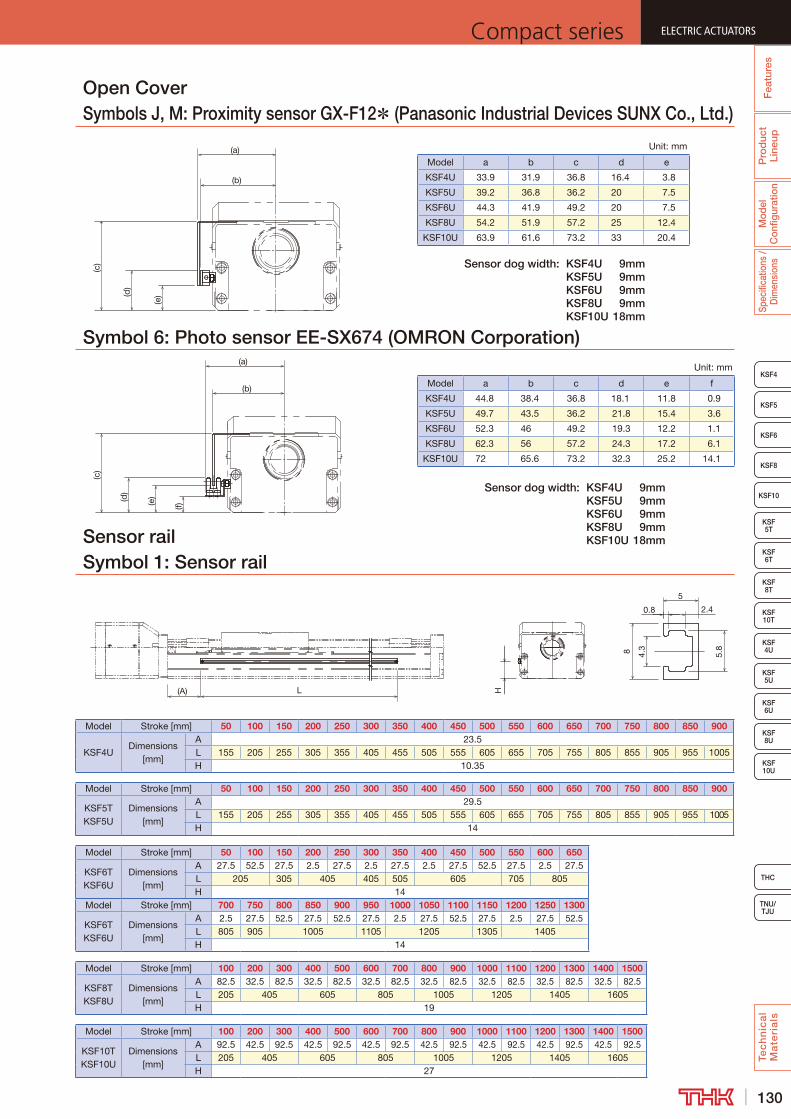
130
ELECTRIC ACTUATORSCompact series
THC
TNU/TJU
KSF8
KSF4
KSF5
KSF6
KSF 10T
KSF10
KSF 5T
KSF 6T
KSF 8T
KSF 10U
KSF 4U
KSF 5U
KSF 6U
KSF 8U
Fea
ture
sP
rod
uct
Line
upM
odel
C
onfig
urat
ion
Spec
ifica
tions
/ D
imen
sion
sTe
ch
nic
al
Ma
teri
als
Open CoverSymbols J, M: Proximity sensor GX-F12* (Panasonic Industrial Devices SUNX Co., Ltd.)
Symbol 6: Photo sensor EE-SX674 (OMRON Corporation)
Unit: mm
Model a b c d e
KSF4U 33.9 31.9 36.8 16.4 3.8
KSF5U 39.2 36.8 36.2 20 7.5
KSF6U 44.3 41.9 49.2 20 7.5
KSF8U 54.2 51.9 57.2 25 12.4
KSF10U 63.9 61.6 73.2 33 20.4
Unit: mm
Model a b c d e f
KSF4U 44.8 38.4 36.8 18.1 11.8 0.9
KSF5U 49.7 43.5 36.2 21.8 15.4 3.6
KSF6U 52.3 46 49.2 19.3 12.2 1.1
KSF8U 62.3 56 57.2 24.3 17.2 6.1
KSF10U 72 65.6 73.2 32.3 25.2 14.1
Sensor dog width: KSF4U 9mm KSF5U 9mm KSF6U 9mm KSF8U 9mm KSF10U 18mm
Sensor dog width: KSF4U 9mm KSF5U 9mm KSF6U 9mm KSF8U 9mm KSF10U 18mm
(a)
(b)
(c)
(d)
(e)
(a)
(b)
(c)
(d)
(e)
(f)
Sensor railSymbol 1: Sensor rail
(A) L H
5
2.40.8
5.8
4.38
Model Stroke [mm] 50 100 150 200 250 300 350 400 450 500 550 600 650 700 750 800 850 900
KSF4UDimensions
[mm]
A 23.5L 155 205 255 305 355 405 455 505 555 605 655 705 755 805 855 905 955 1005H 10.35
Model Stroke [mm] 50 100 150 200 250 300 350 400 450 500 550 600 650 700 750 800 850 900
KSF5TKSF5U
Dimensions [mm]
A 29.5L 155 205 255 305 355 405 455 505 555 605 655 705 755 805 855 905 955 1005H 14
Model Stroke [mm] 50 100 150 200 250 300 350 400 450 500 550 600 650
KSF6TKSF6U
Dimensions [mm]
A 27.5 52.5 27.5 2.5 27.5 2.5 27.5 2.5 27.5 52.5 27.5 2.5 27.5L 205 305 405 405 505 605 705 805H 14
Model Stroke [mm] 700 750 800 850 900 950 1000 1050 1100 1150 1200 1250 1300
KSF6TKSF6U
Dimensions [mm]
A 2.5 27.5 52.5 27.5 52.5 27.5 2.5 27.5 52.5 27.5 2.5 27.5 52.5L 805 905 1005 1105 1205 1305 1405H 14
Model Stroke [mm] 100 200 300 400 500 600 700 800 900 1000 1100 1200 1300 1400 1500
KSF8TKSF8U
Dimensions [mm]
A 82.5 32.5 82.5 32.5 82.5 32.5 82.5 32.5 82.5 32.5 82.5 32.5 82.5 32.5 82.5L 205 405 605 805 1005 1205 1405 1605H 19
Model Stroke [mm] 100 200 300 400 500 600 700 800 900 1000 1100 1200 1300 1400 1500
KSF10TKSF10U
Dimensions [mm]
A 92.5 42.5 92.5 42.5 92.5 42.5 92.5 42.5 92.5 42.5 92.5 42.5 92.5 42.5 92.5L 205 405 605 805 1005 1205 1405 1605H 27
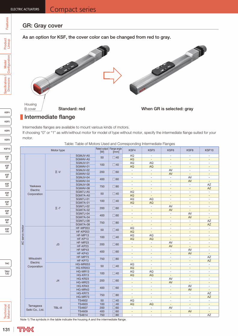
131
ELECTRIC ACTUATORS Compact series
KSF8
KSF4
KSF5
KSF6
KSF 10T
KSF10
KSF 5T
KSF 6T
KSF 8T
KSF 10U
KSF 4U
KSF 5U
KSF 6U
KSF 8U
TNU/TJU
THC
Fea
ture
sP
rod
uct
Line
upM
odel
C
onfig
urat
ion
Spec
ifica
tions
/ D
imen
sion
sTe
ch
nic
al
Ma
teri
als
Intermediate flange
Motor type Rated output [W]
Flange angle [mm] KSF4 KSF5 KSF6 KSF8 KSF10
AC
ser
vo m
otor
Yaskawa Electric
Corporation
Σ-V
SGMJV-A550 □40
AQ - - - -SGMAV-A5 AQ - - - -SGMJV-01
100 □40AQ AQ - - -
SGMAV-01 AQ AQ - - -SGMJV-02
200 □60- - AV - -
SGMAV-02 - - AV - -SGMJV-04
400 □60- - - AV -
SGMAV-04 - - - AV -SGMJV-08
750 □80- - - - AZ
SGMAV-08 - - - - AZ
Σ-7
SGM7J-A550 □40
AQ - - - -SGM7A-A5 AQ - - - -SGM7J-01
100 □40AQ AQ - - -
SGM7A-01 AQ AQ - - -SGM7J-02
200 □60- - AV - -
SGM7A-02 - - AV - -SGM7J-04
400 □60- - - AV -
SGM7A-04 - - - AV -SGM7J-08
750 □80- - - - AZ
SGM7A-08 - - - - AZ
Mitsubishi Electric
Corporation
J3
HF-MP05350 □40
AQ - - - -HF-KP053 AQ - - - -HF-MP13
100 □40AQ AQ - - -
HF-KP13 AQ AQ - - -HF-MP23
200 □60- - AV - -
HF-KP23 - - AV - -HF-MP43
400 □60- - - AV -
HF-KP43 - - - AV -HF-MP73
750 □80- - - - AZ
HF-KP73 - - - - AZ
J4
HG-MR05350 □40
AQ - - - -HG-KR053 AQ - - - -HG-MR13
100 □40AQ AQ - - -
HG-KR13 AQ AQ - - -HG-KR23
200 □60- - AV - -
HG-MR23 - - AV - -HG-KR43
400 □60- - - AV -
HG-MR43 - - - AV -HG-KR73
750 □80- - - - AZ
HG-MR73 - - - - AZ
Tamagawa Seiki Co., Ltd.
TBL-iII
TS4602 50 □40 AQ - - - -TS4603 100 □40 AQ AQ - - -TS4607 200 □60 - - AV - -TS4609 400 □60 - - - AV -TS4614 750 □80 - - - - AZ
Note 1) The symbols in the table indicate the housing A and the intermediate flange.
GR: Gray cover
As an option for KSF, the cover color can be changed from red to gray.
Standard: red When GR is selected: gray
n option for KSF, the cover color can nged from red to gray.

132
ELECTRIC ACTUATORSCompact series
THC
TNU/TJU
KSF8
KSF4
KSF5
KSF6
KSF 10T
KSF10
KSF 5T
KSF 6T
KSF 8T
KSF 10U
KSF 4U
KSF 5U
KSF 6U
KSF 8U
Fea
ture
sP
rod
uct
Line
upM
odel
C
onfig
urat
ion
Spec
ifica
tions
/ D
imen
sion
sTe
ch
nic
al
Ma
teri
als
Motor type Rated output [W]
Flange angle [mm] KSF4 KSF5 KSF6 KSF8 KSF10
AC
ser
vo m
otor
Panasonic Corporation
MINAS A5
MSMD5A50 □38
AP - - - -MSME5A AP - - - -MSMD01
100 □38AP AP - - -
MSME01 AP AP - - -MSMD02
200 □60- - AY - -
MSME02 - - AY - -MSMD04
400 □60- - - AY -
MSME04 - - - AY -MSMD08
750 □80- - - - A5
MSME08 - - - - A5
Sanyo Denki Co., Ltd.
SANMOTION R
R2AA04005 50 □40 AQ - - - -R2AA04010 100 □40 AQ AQ - - -R2AA06020 200 □60 - - AV - -R2AA06040 400 □60 - - - AV -
Omron Corporation
OMNUC G5
R88M-K05030 50 □40 AQ - - - -R88M-K10030 100 □40 AQ AQ - - -R88M-K20030 200 □60 - - AY AY -R88M-K40030 400 □60 - - - AY -R88M-K75030 750 □80 - - - - A5
Fanuc Corporation β is series
βis0.2/5000 50 □40 AQ - - - -βis0.3/5000 100 □40 AQ AQ - - -
Keyence Corporation
SV
SV-M005 50 □40 AQ - - - -SV-M010 100 □40 AQ AQ - - -SV-M020 200 □60 - - AV - -SV-M040 400 □60 - - - AV -SV-M075 750 □80 - - - - AZ
Ste
pp
er m
otor
Oriental Motor Co. Ltd.
α stepAS46, ASC46, AR46 □42 AR AR - - -AS6 , ASC66, AR6 □60 - - AU AU -AR9 , ARL9 , AS9 □85 - - - - A6
5 phase
CRKCRK54 □42 AR AR - - -CRK56 □60 - - AU AU -
CSK IICSK54 □42 AR AR - - -CSK56 □60 - - AU AU -
RK IIRKS54 □42 AR AR - - -RKS56 □60 - - AU AU -RKS59 □85 - - - - A6
2 phaseUMK UMK24 □42 AR AR - - -CSK CSK24 □42 AR AR - - -
Note 1) The symbols in the table indicate the housing A and the intermediate flange.
Note 2) See the KSF technical materials for couplings used with installing the motors listed in the table. (→P.153)
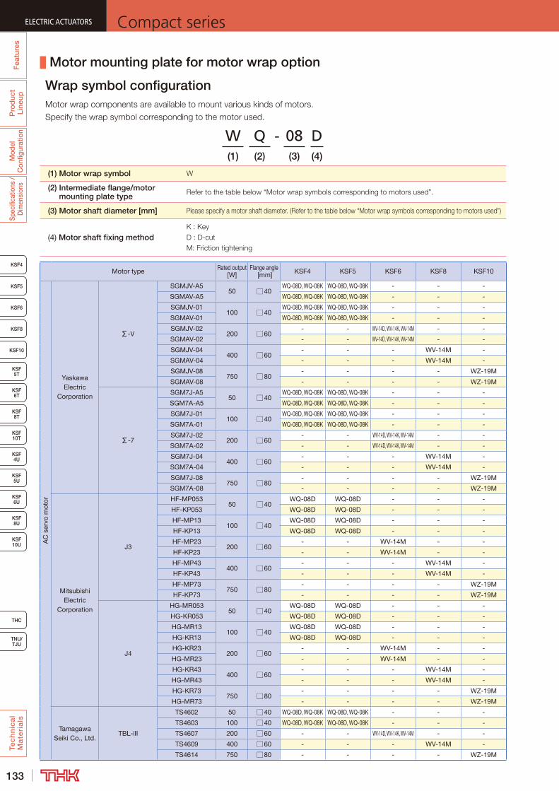
133
ELECTRIC ACTUATORS Compact series
KSF8
KSF4
KSF5
KSF6
KSF 10T
KSF10
KSF 5T
KSF 6T
KSF 8T
KSF 10U
KSF 4U
KSF 5U
KSF 6U
KSF 8U
TNU/TJU
THC
Fea
ture
sP
rod
uct
Line
upM
odel
C
onfig
urat
ion
Spec
ifica
tions
/ D
imen
sion
sTe
ch
nic
al
Ma
teri
als
Motor type Rated output [W]
Flange angle [mm] KSF4 KSF5 KSF6 KSF8 KSF10
AC
ser
vo m
otor
Yaskawa Electric
Corporation
Σ-V
SGMJV-A550 □40
WQ-08D, WQ-08K WQ-08D, WQ-08K - - -
SGMAV-A5 WQ-08D, WQ-08K WQ-08D, WQ-08K - - -
SGMJV-01100 □40
WQ-08D, WQ-08K WQ-08D, WQ-08K - - -
SGMAV-01 WQ-08D, WQ-08K WQ-08D, WQ-08K - - -
SGMJV-02200 □60
- - WV-14D, WV-14K, WV-14M - -
SGMAV-02 - - WV-14D, WV-14K, WV-14M - -
SGMJV-04400 □60
- - - WV-14M -
SGMAV-04 - - - WV-14M -
SGMJV-08750 □80
- - - - WZ-19M
SGMAV-08 - - - - WZ-19M
Σ-7
SGM7J-A550 □40
WQ-08D, WQ-08K WQ-08D, WQ-08K - - -
SGM7A-A5 WQ-08D, WQ-08K WQ-08D, WQ-08K - - -
SGM7J-01100 □40
WQ-08D, WQ-08K WQ-08D, WQ-08K - - -
SGM7A-01 WQ-08D, WQ-08K WQ-08D, WQ-08K - - -
SGM7J-02200 □60
- - WV-14D, WV-14K, WV-14M - -
SGM7A-02 - - WV-14D, WV-14K, WV-14M - -
SGM7J-04400 □60
- - - WV-14M -
SGM7A-04 - - - WV-14M -
SGM7J-08750 □80
- - - - WZ-19M
SGM7A-08 - - - - WZ-19M
Mitsubishi Electric
Corporation
J3
HF-MP05350 □40
WQ-08D WQ-08D - - -
HF-KP053 WQ-08D WQ-08D - - -
HF-MP13100 □40
WQ-08D WQ-08D - - -
HF-KP13 WQ-08D WQ-08D - - -
HF-MP23200 □60
- - WV-14M - -
HF-KP23 - - WV-14M - -
HF-MP43400 □60
- - - WV-14M -
HF-KP43 - - - WV-14M -
HF-MP73750 □80
- - - - WZ-19M
HF-KP73 - - - - WZ-19M
J4
HG-MR05350 □40
WQ-08D WQ-08D - - -
HG-KR053 WQ-08D WQ-08D - - -
HG-MR13100 □40
WQ-08D WQ-08D - - -
HG-KR13 WQ-08D WQ-08D - - -
HG-KR23200 □60
- - WV-14M - -
HG-MR23 - - WV-14M - -
HG-KR43400 □60
- - - WV-14M -
HG-MR43 - - - WV-14M -
HG-KR73750 □80
- - - - WZ-19M
HG-MR73 - - - - WZ-19M
Tamagawa Seiki Co., Ltd.
TBL-iII
TS4602 50 □40 WQ-08D, WQ-08K WQ-08D, WQ-08K - - -
TS4603 100 □40 WQ-08D, WQ-08K WQ-08D, WQ-08K - - -
TS4607 200 □60 - - WV-14D, WV-14K, WV-14M - -
TS4609 400 □60 - - - WV-14M -
TS4614 750 □80 - - - - WZ-19M
Motor mounting plate for motor wrap option
Wrap symbol configuration
W Q - 08 D(1) (2) (3) (4)
(1) Motor wrap symbol
(2) Intermediate flange/motor mounting plate type
(3) Motor shaft diameter [mm]
(4) Motor shaft fixing method
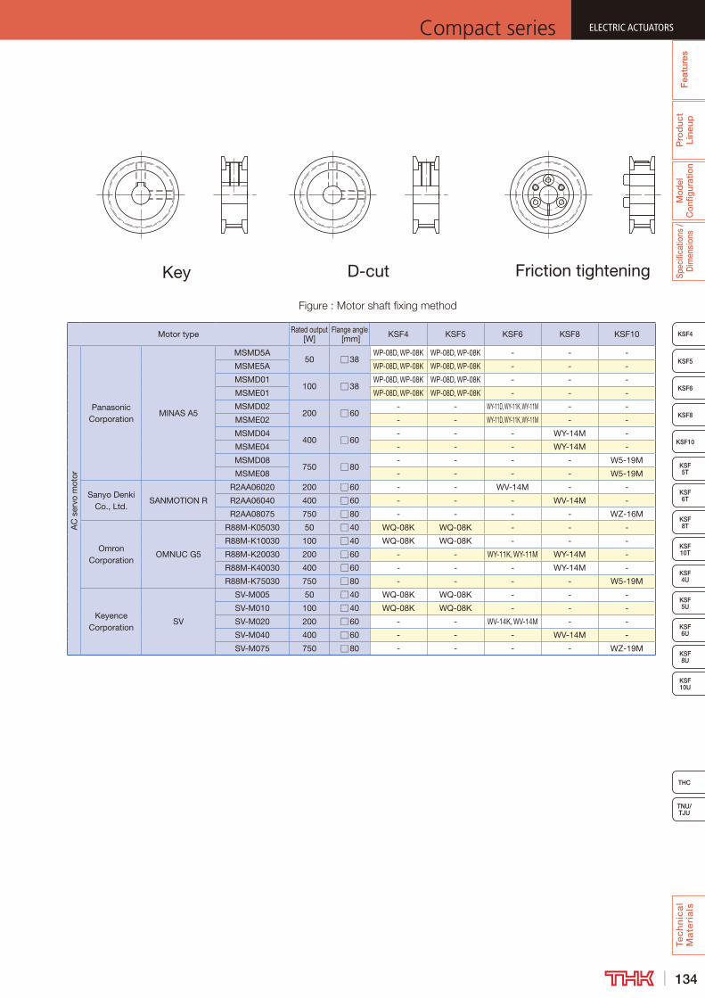
134
ELECTRIC ACTUATORSCompact series
THC
TNU/TJU
KSF8
KSF4
KSF5
KSF6
KSF 10T
KSF10
KSF 5T
KSF 6T
KSF 8T
KSF 10U
KSF 4U
KSF 5U
KSF 6U
KSF 8U
Fea
ture
sP
rod
uct
Line
upM
odel
C
onfig
urat
ion
Spec
ifica
tions
/ D
imen
sion
sTe
ch
nic
al
Ma
teri
als
Friction tighteningKey D-cut
Motor type Rated output [W]
Flange angle [mm] KSF4 KSF5 KSF6 KSF8 KSF10
AC
ser
vo m
otor
Panasonic Corporation
MINAS A5
MSMD5A50 □38
WP-08D, WP-08K WP-08D, WP-08K - - -
MSME5A WP-08D, WP-08K WP-08D, WP-08K - - -
MSMD01100 □38
WP-08D, WP-08K WP-08D, WP-08K - - -
MSME01 WP-08D, WP-08K WP-08D, WP-08K - - -
MSMD02200 □60
- - WY-11D, WY-11K, WY-11M - -
MSME02 - - WY-11D, WY-11K, WY-11M - -
MSMD04400 □60
- - - WY-14M -
MSME04 - - - WY-14M -
MSMD08750 □80
- - - - W5-19M
MSME08 - - - - W5-19M
Sanyo Denki Co., Ltd.
SANMOTION R
R2AA06020 200 □60 - - WV-14M - -
R2AA06040 400 □60 - - - WV-14M -
R2AA08075 750 □80 - - - - WZ-16M
Omron Corporation
OMNUC G5
R88M-K05030 50 □40 WQ-08K WQ-08K - - -
R88M-K10030 100 □40 WQ-08K WQ-08K - - -
R88M-K20030 200 □60 - - WY-11K, WY-11M WY-14M -
R88M-K40030 400 □60 - - - WY-14M -
R88M-K75030 750 □80 - - - - W5-19M
Keyence Corporation
SV
SV-M005 50 □40 WQ-08K WQ-08K - - -
SV-M010 100 □40 WQ-08K WQ-08K - - -
SV-M020 200 □60 - - WV-14K, WV-14M - -
SV-M040 400 □60 - - - WV-14M -
SV-M075 750 □80 - - - - WZ-19M
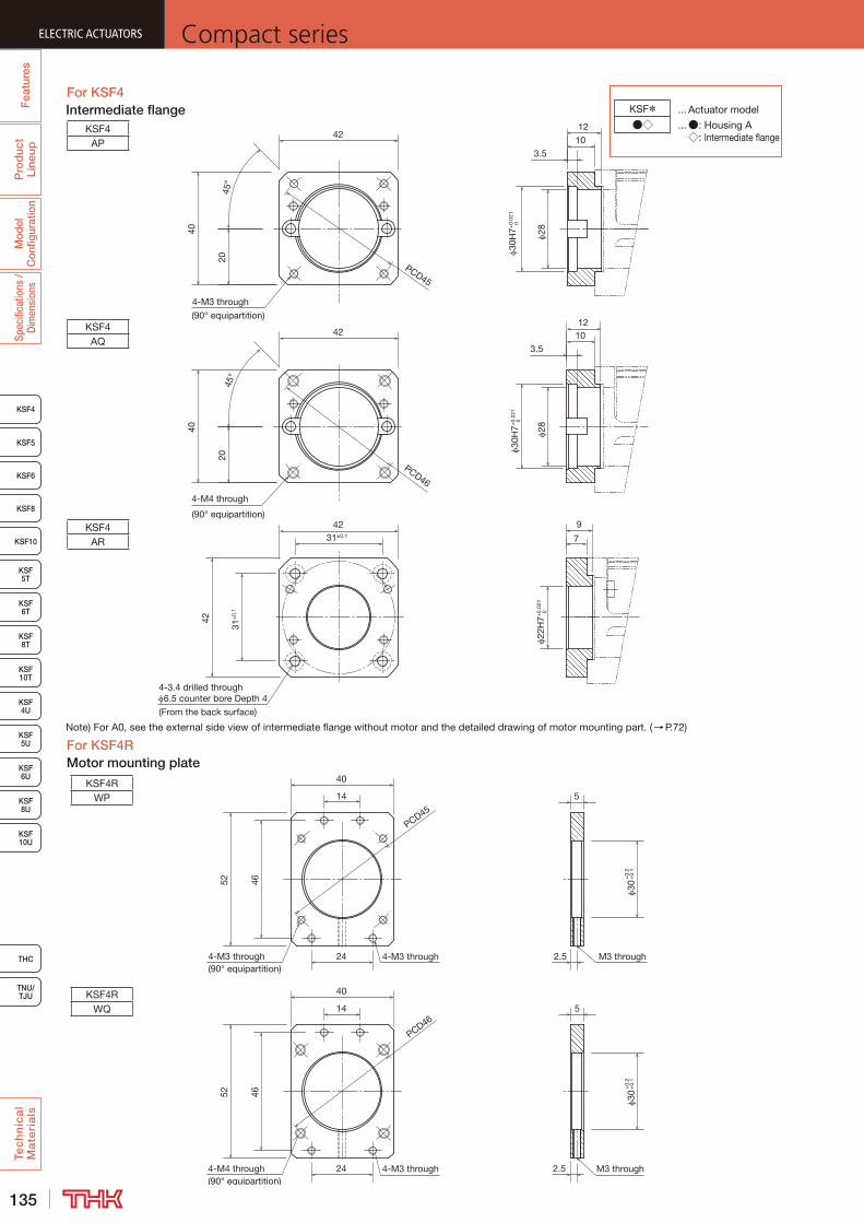
135
ELECTRIC ACTUATORS Compact series
KSF8
KSF4
KSF5
KSF6
KSF 10T
KSF10
KSF 5T
KSF 6T
KSF 8T
KSF 10U
KSF 4U
KSF 5U
KSF 6U
KSF 8U
TNU/TJU
THC
Fea
ture
sP
rod
uct
Line
upM
odel
C
onfig
urat
ion
Spec
ifica
tions
/ D
imen
sion
sTe
ch
nic
al
Ma
teri
als
For KSF4
For KSF4RMotor mounting plate
4-M3 through
(90° equipartition)
4-3.4 drilled through 6.5 counter bore Depth 4
(From the back surface)
4-M4 through
(90° equipartition)
31±
0.1
7
42
42
PCD46
42
31±0.128
28
45°
20
40
3.51012
3.51012
9
42
40
PCD45
2045
°
30H
7+0.
021
030
H7+
0.02
1 0
22H
7+0.
021
0
KSF4AP
KSF4AQ
KSF4AR
Note) For A0, see the external side view of intermediate flange without motor and the detailed drawing of motor mounting part. (→P.72)
PCD45
4-M3 through
40
52 46
24
14
4-M3 through(90° equipartition)
30+
0.2
+0.
1
5
4-M4 through(90° equipartition)
14
24
4652
5
4-M3 through
40
PCD46
M3 through2.5
2.5 M3 through
30+
0.2
+0.
1
KSF4RWP
KSF4RWQ
Intermediate flange KSF*●◇ ... ●: Housing A
◇: Intermediate flange
... Actuator model
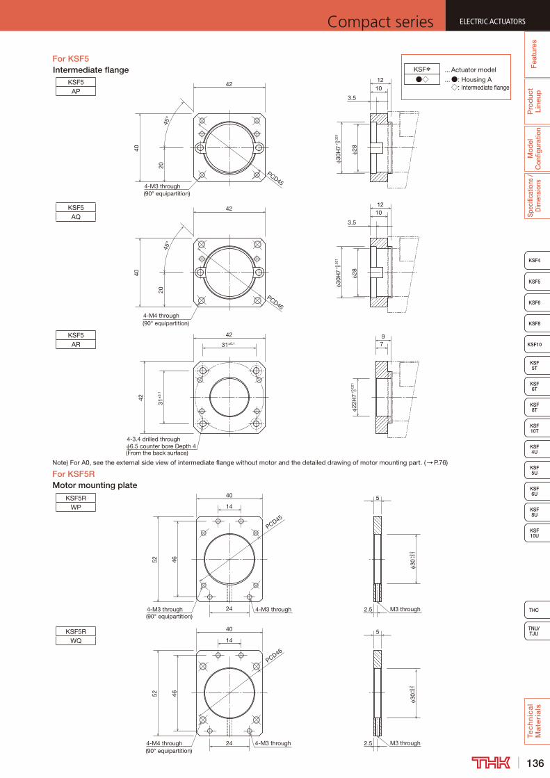
136
ELECTRIC ACTUATORSCompact series
THC
TNU/TJU
KSF8
KSF4
KSF5
KSF6
KSF 10T
KSF10
KSF 5T
KSF 6T
KSF 8T
KSF 10U
KSF 4U
KSF 5U
KSF 6U
KSF 8U
Fea
ture
sP
rod
uct
Line
upM
odel
C
onfig
urat
ion
Spec
ifica
tions
/ D
imen
sion
sTe
ch
nic
al
Ma
teri
als
Note) For A0, see the external side view of intermediate flange without motor and the detailed drawing of motor mounting part. (→P.76)
For KSF5RMotor mounting plate
14
M3 through4-M4 through(90° equipartition)
30+
0.2
+0.
1
46
5
2.5
52
4-M3 through24
PCD46
40
40
PCD45
4-M3 through
30+
0.2
+0.
1
2.5
5
M3 through
52 46
24
14
4-M3 through(90° equipartition)
KSF5RWP
KSF5RWQ
For KSF5Intermediate flange
42
4-3.4 drilled through 6.5 counter bore Depth 4
(From the back surface)
31±
0.1
4-M3 through(90° equipartition)
7
42
3.5
12
40
PCD46
42
31±0.1
4-M4 through(90° equipartition)
PCD45
30H
7+
0.02
10
22H
7+
0.02
10
28
10
2045
°45
°20
42
40
12
3.5
30H
7+
0.02
10
28
10
9
KSF5AP
KSF5AQ
KSF5AR
KSF*●◇ ... ●: Housing A
◇: Intermediate flange
... Actuator model
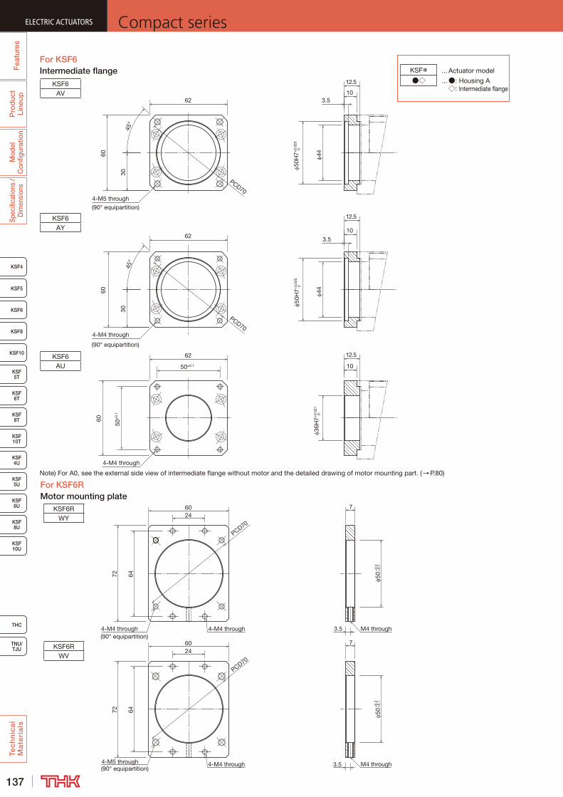
137
ELECTRIC ACTUATORS Compact series
KSF8
KSF4
KSF5
KSF6
KSF 10T
KSF10
KSF 5T
KSF 6T
KSF 8T
KSF 10U
KSF 4U
KSF 5U
KSF 6U
KSF 8U
TNU/TJU
THC
Fea
ture
sP
rod
uct
Line
upM
odel
C
onfig
urat
ion
Spec
ifica
tions
/ D
imen
sion
sTe
ch
nic
al
Ma
teri
als
Intermediate flangeFor KSF6
4-M5 through(90° equipartition)
4-M4 through
4-M4 through
(90° equipartition)
PCD70
PCD70
10
6260
60
44
3.510
30
3.5
45°
44
10
62
45°
12.5
50±0.1
12.5
60
50±
0.1
62
12.5
30
KSF6AV
KSF6AY
KSF6AU
50H
7+0.
025
050
H7+
0.02
5 0
36H
7+0.
021
0
Note) For A0, see the external side view of intermediate flange without motor and the detailed drawing of motor mounting part. (→P.80)
For KSF6RMotor mounting plate
6024
72
PCD70
4-M4 through(90° equipartition)
4-M4 through 3.5
50+
0.2
+0.
1
M4 through
64
72
2460
PCD70
4-M5 through(90° equipartition)
4-M4 through 3.5
50+
0.2
+0.
1
M4 through
64
7
7KSF6RWY
KSF6RWV
KSF*●◇ ... ●: Housing A
◇: Intermediate flange
... Actuator model
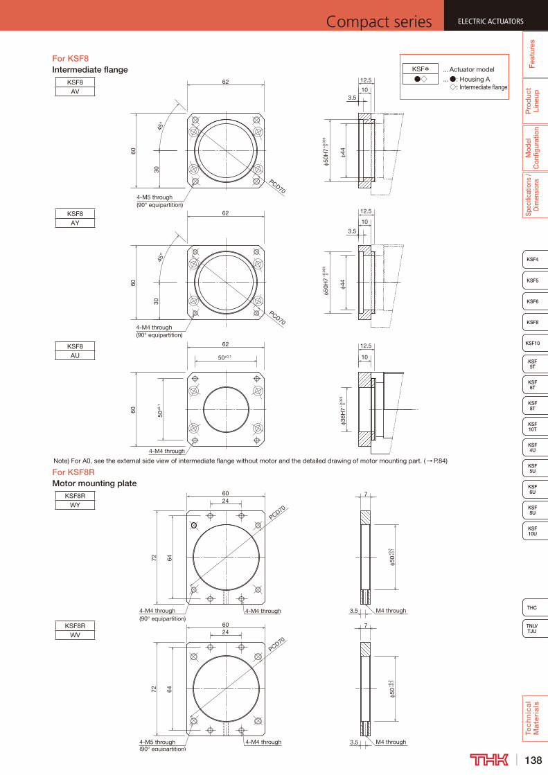
138
ELECTRIC ACTUATORSCompact series
THC
TNU/TJU
KSF8
KSF4
KSF5
KSF6
KSF 10T
KSF10
KSF 5T
KSF 6T
KSF 8T
KSF 10U
KSF 4U
KSF 5U
KSF 6U
KSF 8U
Fea
ture
sP
rod
uct
Line
upM
odel
C
onfig
urat
ion
Spec
ifica
tions
/ D
imen
sion
sTe
ch
nic
al
Ma
teri
als
Note) For A0, see the external side view of intermediate flange without motor and the detailed drawing of motor mounting part. (→P.84)
Intermediate flangeFor KSF8
For KSF8RMotor mounting plate
PCD70
36H
7+
0.02
50
10
60
3.5
44
62
50H
7+
0.02
50
4-M4 through(90° equipartition)
60
4-M4 through
50±
0.1
62
50±0.1 10
4-M5 through(90° equipartition)
3045
°
12.5
45°
PCD70
60
62
30
12.5
10
3.5
44
50H
7+
0.02
5 0
12.5
KSF8AV
KSF8AY
KSF8AU
6024
72
PCD70
4-M4 through(90° equipartition)
4-M4 through 3.5
50+
0.2
+0.
1
M4 through
64
72
2460
PCD70
4-M5 through(90° equipartition)
4-M4 through 3.5
50+
0.2
+0.
1
M4 through
64
7
7
KSF8RWY
KSF8RWV
KSF*●◇ ... ●: Housing A
◇: Intermediate flange
... Actuator model
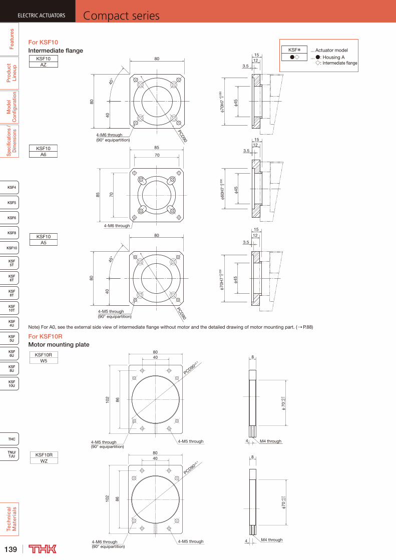
139
ELECTRIC ACTUATORS Compact series
KSF8
KSF4
KSF5
KSF6
KSF 10T
KSF10
KSF 5T
KSF 6T
KSF 8T
KSF 10U
KSF 4U
KSF 5U
KSF 6U
KSF 8U
TNU/TJU
THC
Fea
ture
sP
rod
uct
Line
upM
odel
C
onfig
urat
ion
Spec
ifica
tions
/ D
imen
sion
sTe
ch
nic
al
Ma
teri
als
Intermediate flangeFor KSF10
Note) For A0, see the external side view of intermediate flange without motor and the detailed drawing of motor mounting part. (→P.88)
For KSF10RMotor mounting plate
KSF*●◇ ... ●: Housing A
◇: Intermediate flange
... Actuator model
4-M5 through(90° equipartition)
102
86
PCD90±0.1
80
4-M5 through
40
4 M4 through
70+
0.2
+0.
1
8
4 M4 through
70+
0.2
+0.
1
8
4-M6 through(90° equipartition)
102
86
PCD90±0.1
80
4-M5 through
40
KSF10RW5
KSF10RWZ
70
85
85 70
4-M6 through
KSF10AZ
12
70H
7+
0.03
00
3.5
45
15
123.5
60H
7+
0.03
00
45
15
12
70H
7+
0.03
00
3.5
4515
4-M5 through(90° equipartition)
80
PCD
90
45°
40
80
KSF10A5
KSF10A6
80
80
PCD
90
45°
4-M6 through(90° equipartition)
40
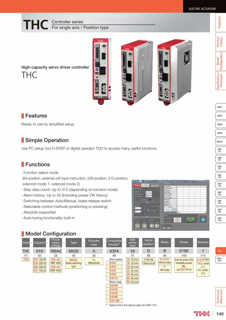
140
ELECTRIC ACTUATORSCompact series
Pro
duc
t Li
neup
Mod
el
Con
figur
atio
nSp
ecifi
catio
ns /
Dim
ensi
ons
Tec
hn
ica
l M
ate
ria
ls
TNU/TJU
KSF8
KSF4
KSF5
KSF6
KSF 10T
KSF10
KSF 5T
KSF 6T
KSF 8T
KSF 10U
KSF 4U
KSF 5U
KSF 6U
KSF 8U
THC
Fea
ture
s
ELECTRIC ACTUATORSCompact series
THC
High-capacity servo driver controller
THC
Features
Simple Operation
Functions
Controller seriesFor single axis / Position type
Model Configuration
Model - Capacity -Power supply voltage
- Type -Encoder
type-
Compatible actuator
-Ball
screw lead
-Home
position - Brake - Stroke - Sensors
THC 010 100AC MOD A KSF4 10 D B 0100 1(1) (2) (3) (4) (5) (6) (7) (8) (9) (10) (11)
THC 010: 100 W 100 AC: 100 VAC
MOD: Mode switching
type
A: Absolute
Direct coupling 10: 10 mm D: Motor side No symbol: Without brake
Enter the stroke of the compatible actuator
(6), e.g.) 0050: 50 mm
No symbol:None020: 200 W KSF4 16: 16 mm R: Reverse motor side 1: N.O. contact
[x 1]N.C. contact
[x 2]
040: 400 W 200 AC: 200 VAC
KSF5 20: 20 mm B: With brake075: 750 W KSF6 25: 25 mm
KSF8 30: 30 mmKSF10 40: 40 mmMotor wrap 50: 40 mmKSF4RKSF5RKSF6RKSF8RKSF10R
Select from the above also for KSF-T/U.
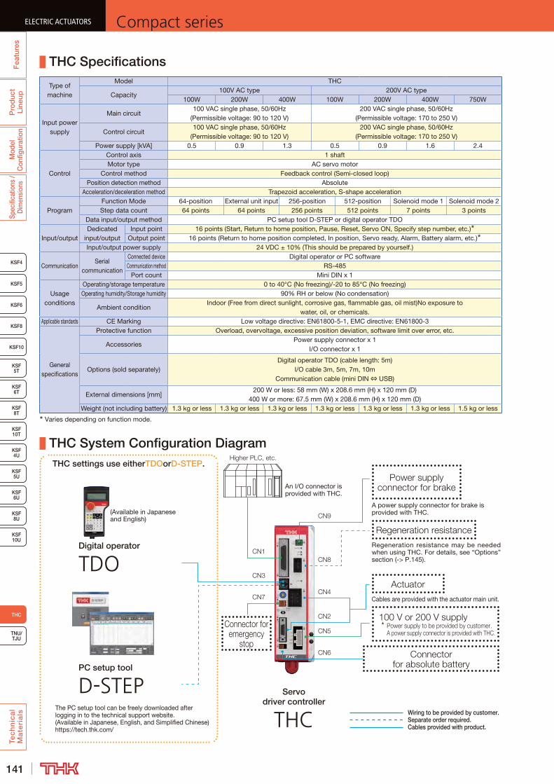
141
ELECTRIC ACTUATORS Compact seriesP
rod
uct
Line
upM
odel
C
onfig
urat
ion
Spec
ifica
tions
/ D
imen
sion
sTe
ch
nic
al
Ma
teri
als
KSF8
KSF4
KSF5
KSF6
KSF 10T
KSF10
KSF 5T
KSF 6T
KSF 8T
KSF 10U
KSF 4U
KSF 5U
KSF 6U
KSF 8U
TNU/TJU
THC
Fea
ture
sELECTRIC ACTUATORS Compact series
THC Specifications
Type of machine
Model THC
Capacity100V AC type 200V AC type
100W 200W 400W 100W 200W 400W 750W
Input power supply
Main circuit100 VAC single phase, 50/60Hz
(Permissible voltage: 90 to 120 V)200 VAC single phase, 50/60Hz
(Permissible voltage: 170 to 250 V)
Control circuit100 VAC single phase, 50/60Hz
(Permissible voltage: 90 to 120 V)200 VAC single phase, 50/60Hz
(Permissible voltage: 170 to 250 V)Power supply [kVA] 0.5 0.9 1.3 0.5 0.9 1.6 2.4
Control
Control axis 1 shaftMotor type AC servo motor
Control method Feedback control (Semi-closed loop)Position detection method Absolute
Acceleration/deceleration method Trapezoid acceleration, S-shape acceleration
ProgramFunction Mode 64-position External unit input 256-position 512-position Solenoid mode 1 Solenoid mode 2Step data count 64 points 64 points 256 points 512 points 7 points 3 points
Data input/output method PC setup tool D-STEP or digital operator TDO
Input/outputDedicated
input/outputInput point 16 points (Start, Return to home position, Pause, Reset, Servo ON, Specify step number, etc.)
Output point 16 points (Return to home position completed, In position, Servo ready, Alarm, Battery alarm, etc.)Input/output power supply 24 VDC ± 10% (This should be prepared by yourself.)
CommunicationSerial
communication
Connected device Digital operator or PC softwareCommunication method RS-485
Port count Mini DIN x 1
Usage conditions
Operating/storage temperature 0 to 40°C (No freezing)/-20 to 85°C (No freezing)Operating humidity/Storage humidity 90% RH or below (No condensation)
Ambient conditionIndoor (Free from direct sunlight, corrosive gas, flammable gas, oil mist)No exposure to
water, oil, or chemicals.Applicable standards CE Marking Low voltage directive: EN61800-5-1, EMC directive: EN61800-3
General specifications
Protective function Overload, overvoltage, excessive position deviation, software limit over error, etc.
AccessoriesPower supply connector x 1
I/O connector x 1
Options (sold separately)Digital operator TDO (cable length: 5m)
I/O cable 3m, 5m, 7m, 10m Communication cable (mini DIN ⇔ USB)
External dimensions [mm]200 W or less: 58 mm (W) x 208.6 mm (H) x 120 mm (D)
400 W or more: 67.5 mm (W) x 208.6 mm (H) x 120 mm (D)Weight (not including battery) 1.3 kg or less 1.3 kg or less 1.3 kg or less 1.3 kg or less 1.3 kg or less 1.3 kg or less 1.5 kg or less
Varies depending on function mode.
THC System Configuration Diagram
An I/O connector is provided with THC.
Wiring to be provided by customer.Separate order required.Cables provided with product.
Servo driver controller
THC
(Available in Japanese and English)
THC settings use eitherTDOorD-STEP.
Digital operator
TDO
PC setup tool
D-STEPThe PC setup tool can be freely downloaded after logging in to the technical support website. (Available in Japanese, English, and Simplified Chinese)https://tech.thk.com/
Cables are provided with the actuator main unit.
Regeneration resistance may be needed when using THC. For details, see “Options” section (-> P.145).
A power supply connector for brake is provided with THC.
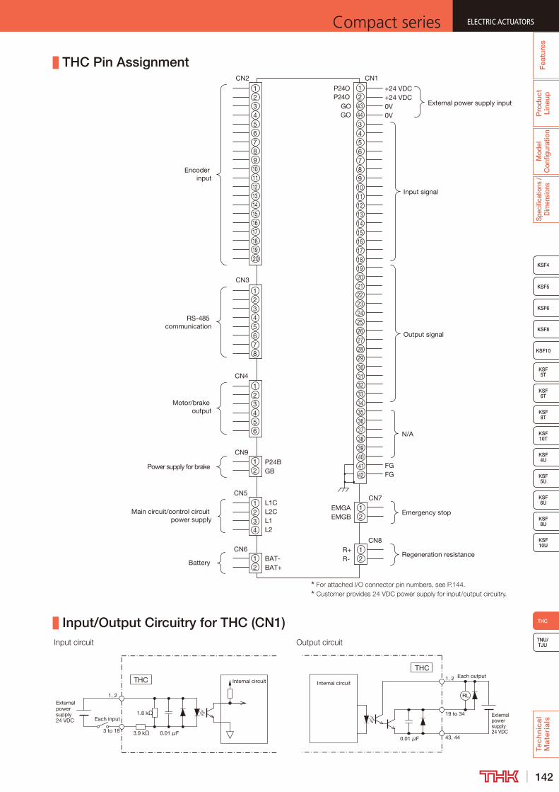
142
ELECTRIC ACTUATORSCompact series
Pro
duc
t Li
neup
Mod
el
Con
figur
atio
nSp
ecifi
catio
ns /
Dim
ensi
ons
Tec
hn
ica
l M
ate
ria
ls
TNU/TJU
KSF8
KSF4
KSF5
KSF6
KSF 10T
KSF10
KSF 5T
KSF 6T
KSF 8T
KSF 10U
KSF 4U
KSF 5U
KSF 6U
KSF 8U
THC
Fea
ture
s
ELECTRIC ACTUATORSCompact series
THC Pin Assignment
21
3456
21
3456
78
21
21
21
21
P24OP24O
GOGO
Input signal
Output signal
+24 VDC+24 VDC0V0V
External power supply input
CN2
CN3
CN4
CN5
CN1
L1CL2CL1L2
RS-485 communication
CN6BAT-BAT+
CN7EMGAEMGB
Emergency stop
CN9P24BGB
CN8R+R-
Regeneration resistance
FGFG
N/A
2021222324252627282930313233343536373839404142
444321
345678910111213141516171819
21
34567891011121314151617181920
Encoder input
Motor/brake output
Power supply for brake
Main circuit/control circuit power supply
Battery
21
34
Input/Output Circuitry for THC (CN1)
THC Internal circuit
External power supply24 VDC
3.9 kΩ
1.8 kΩ
0.01 μF
Each input
1, 2
3 to 18
RL
Internal circuit
External power supply24 VDC
0.01 μF
Each outputTHC
1, 2
19 to 34
43, 44
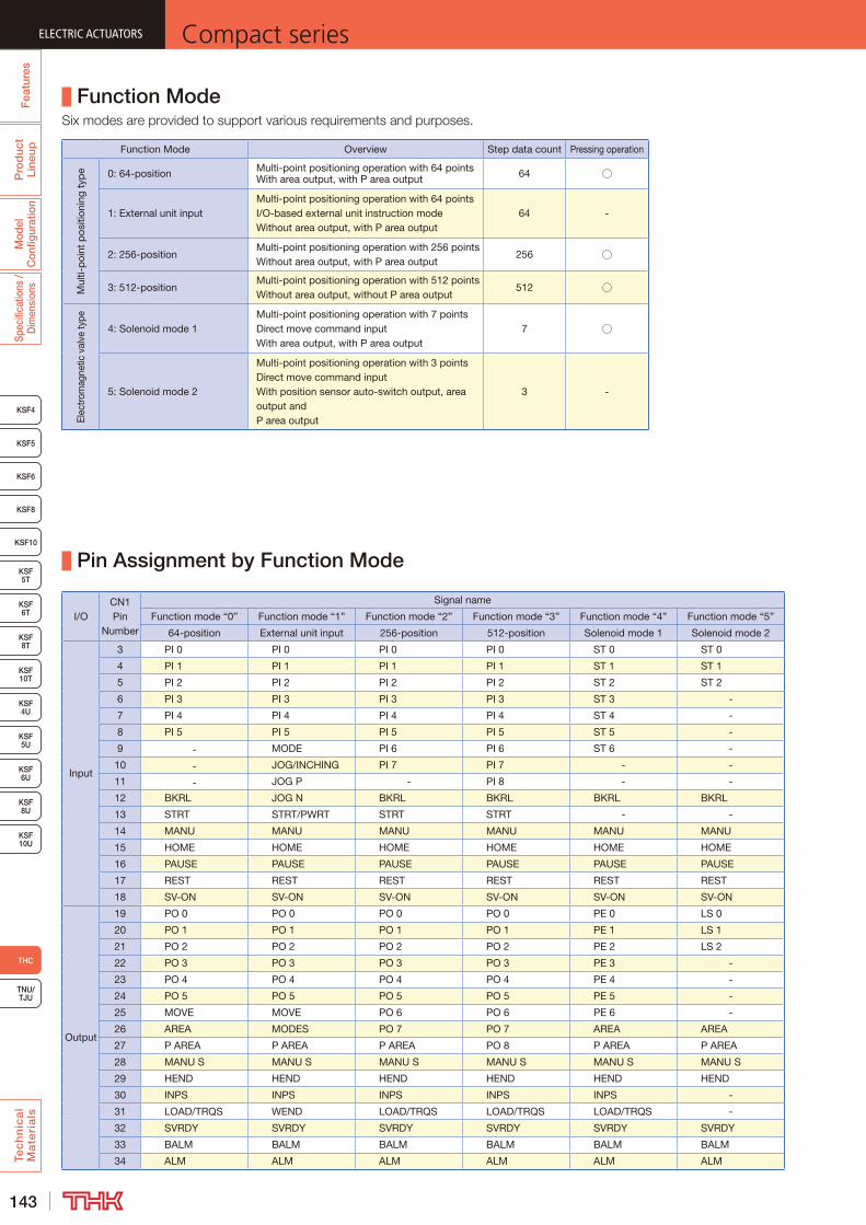
143
ELECTRIC ACTUATORS Compact seriesP
rod
uct
Line
upM
odel
C
onfig
urat
ion
Spec
ifica
tions
/ D
imen
sion
sTe
ch
nic
al
Ma
teri
als
KSF8
KSF4
KSF5
KSF6
KSF 10T
KSF10
KSF 5T
KSF 6T
KSF 8T
KSF 10U
KSF 4U
KSF 5U
KSF 6U
KSF 8U
TNU/TJU
THC
Fea
ture
sELECTRIC ACTUATORS Compact series
Function Mode
Function Mode Overview Step data count Pressing operation
Mul
ti-p
oint
pos
ition
ing
typ
e 0: 64-position Multi-point positioning operation with 64 pointsWith area output, with P area output 64 ○
1: External unit inputMulti-point positioning operation with 64 pointsI/O-based external unit instruction modeWithout area output, with P area output
64 -
2: 256-positionMulti-point positioning operation with 256 pointsWithout area output, with P area output
256 ○
3: 512-positionMulti-point positioning operation with 512 pointsWithout area output, without P area output
512 ○
Elec
trom
agne
tic v
alve
type
4: Solenoid mode 1Multi-point positioning operation with 7 pointsDirect move command inputWith area output, with P area output
7 ○
5: Solenoid mode 2
Multi-point positioning operation with 3 pointsDirect move command inputWith position sensor auto-switch output, area output and P area output
3 -
Pin Assignment by Function Mode
I/OCN1Pin
Number
Signal name
Function mode “0” Function mode “1” Function mode “2” Function mode “3” Function mode “4” Function mode “5”
64-position External unit input 256-position 512-position Solenoid mode 1 Solenoid mode 2
Input
3 PI 0 PI 0 PI 0 PI 0 ST 0 ST 0
4 PI 1 PI 1 PI 1 PI 1 ST 1 ST 1
5 PI 2 PI 2 PI 2 PI 2 ST 2 ST 2
6 PI 3 PI 3 PI 3 PI 3 ST 3 -
7 PI 4 PI 4 PI 4 PI 4 ST 4 -
8 PI 5 PI 5 PI 5 PI 5 ST 5 -
9 - MODE PI 6 PI 6 ST 6 -
10 - JOG/INCHING PI 7 PI 7 - -
11 - JOG P - PI 8 - -
12 BKRL JOG N BKRL BKRL BKRL BKRL
13 STRT STRT/PWRT STRT STRT - -
14 MANU MANU MANU MANU MANU MANU
15 HOME HOME HOME HOME HOME HOME
16 PAUSE PAUSE PAUSE PAUSE PAUSE PAUSE
17 REST REST REST REST REST REST
18 SV-ON SV-ON SV-ON SV-ON SV-ON SV-ON
Output
19 PO 0 PO 0 PO 0 PO 0 PE 0 LS 0
20 PO 1 PO 1 PO 1 PO 1 PE 1 LS 1
21 PO 2 PO 2 PO 2 PO 2 PE 2 LS 2
22 PO 3 PO 3 PO 3 PO 3 PE 3 -
23 PO 4 PO 4 PO 4 PO 4 PE 4 -
24 PO 5 PO 5 PO 5 PO 5 PE 5 -
25 MOVE MOVE PO 6 PO 6 PE 6 -
26 AREA MODES PO 7 PO 7 AREA AREA
27 P AREA P AREA P AREA PO 8 P AREA P AREA
28 MANU S MANU S MANU S MANU S MANU S MANU S
29 HEND HEND HEND HEND HEND HEND
30 INPS INPS INPS INPS INPS -
31 LOAD/TRQS WEND LOAD/TRQS LOAD/TRQS LOAD/TRQS -
32 SVRDY SVRDY SVRDY SVRDY SVRDY SVRDY
33 BALM BALM BALM BALM BALM BALM
34 ALM ALM ALM ALM ALM ALM
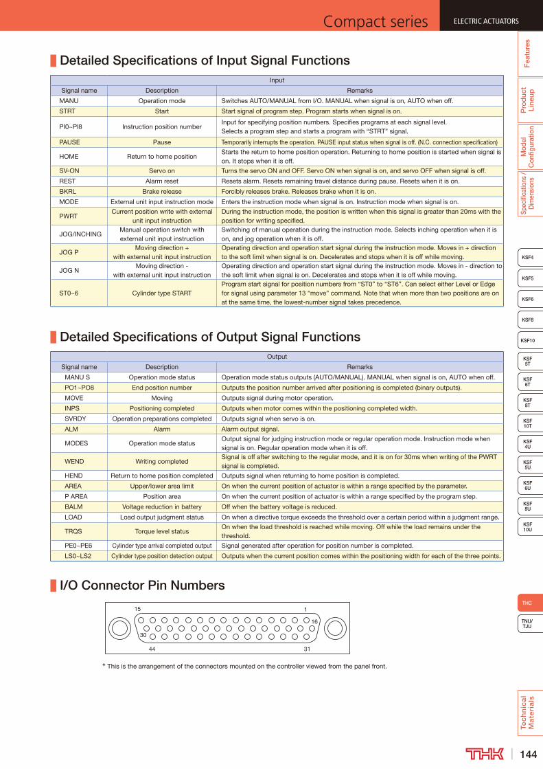
144
ELECTRIC ACTUATORSCompact series
Pro
duc
t Li
neup
Mod
el
Con
figur
atio
nSp
ecifi
catio
ns /
Dim
ensi
ons
Tec
hn
ica
l M
ate
ria
ls
TNU/TJU
KSF8
KSF4
KSF5
KSF6
KSF 10T
KSF10
KSF 5T
KSF 6T
KSF 8T
KSF 10U
KSF 4U
KSF 5U
KSF 6U
KSF 8U
THC
Fea
ture
s
ELECTRIC ACTUATORSCompact series
Detailed Specifications of Input Signal FunctionsInput
Signal name Description Remarks
MANU Operation mode Switches AUTO/MANUAL from I/O. MANUAL when signal is on, AUTO when off.
STRT Start Start signal of program step. Program starts when signal is on.
PI0~PI8 Instruction position numberInput for specifying position numbers. Specifies programs at each signal level.Selects a program step and starts a program with “STRT” signal.
PAUSE Pause Temporarily interrupts the operation. PAUSE input status when signal is off. (N.C. connection specification)
HOME Return to home positionStarts the return to home position operation. Returning to home position is started when signal is on. It stops when it is off.
SV-ON Servo on Turns the servo ON and OFF. Servo ON when signal is on, and servo OFF when signal is off.
REST Alarm reset Resets alarm. Resets remaining travel distance during pause. Resets when it is on.
BKRL Brake release Forcibly releases brake. Releases brake when it is on.
MODE External unit input instruction mode Enters the instruction mode when signal is on. Instruction mode when signal is on.
PWRTCurrent position write with external
unit input instructionDuring the instruction mode, the position is written when this signal is greater than 20ms with the position for writing specified.
JOG/INCHINGManual operation switch with external unit input instruction
Switching of manual operation during the instruction mode. Selects inching operation when it is on, and jog operation when it is off.
JOG PMoving direction +
with external unit input instructionOperating direction and operation start signal during the instruction mode. Moves in + direction to the soft limit when signal is on. Decelerates and stops when it is off while moving.
JOG NMoving direction -
with external unit input instructionOperating direction and operation start signal during the instruction mode. Moves in - direction to the soft limit when signal is on. Decelerates and stops when it is off while moving.
ST0~6 Cylinder type STARTProgram start signal for position numbers from “ST0” to “ST6”. Can select either Level or Edge for signal using parameter 13 “move” command. Note that when more than two positions are on at the same time, the lowest-number signal takes precedence.
Detailed Specifications of Output Signal FunctionsOutput
Signal name Description Remarks
MANU S Operation mode status Operation mode status outputs (AUTO/MANUAL). MANUAL when signal is on, AUTO when off.
PO1~PO8 End position number Outputs the position number arrived after positioning is completed (binary outputs).
MOVE Moving Outputs signal during motor operation.
INPS Positioning completed Outputs when motor comes within the positioning completed width.
SVRDY Operation preparations completed Outputs signal when servo is on.
ALM Alarm Alarm output signal.
MODES Operation mode statusOutput signal for judging instruction mode or regular operation mode. Instruction mode when signal is on. Regular operation mode when it is off.
WEND Writing completedSignal is off after switching to the regular mode, and it is on for 30ms when writing of the PWRT signal is completed.
HEND Return to home position completed Outputs signal when returning to home position is completed.
AREA Upper/lower area limit On when the current position of actuator is within a range specified by the parameter.
P AREA Position area On when the current position of actuator is within a range specified by the program step.
BALM Voltage reduction in battery Off when the battery voltage is reduced.
LOAD Load output judgment status On when a directive torque exceeds the threshold over a certain period within a judgment range.
TRQS Torque level statusOn when the load threshold is reached while moving. Off while the load remains under the threshold.
PE0~PE6 Cylinder type arrival completed output Signal generated after operation for position number is completed.
LS0~LS2 Cylinder type position detection output Outputs when the current position comes within the positioning width for each of the three points.
I/O Connector Pin Numbers
115
16
30
3144
This is the arrangement of the connectors mounted on the controller viewed from the panel front.
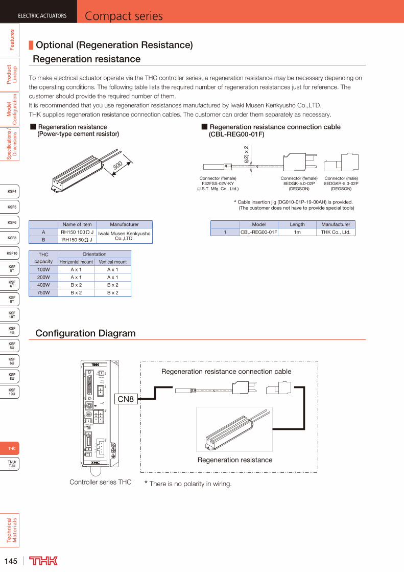
145
ELECTRIC ACTUATORS Compact seriesP
rod
uct
Line
upM
odel
C
onfig
urat
ion
Spec
ifica
tions
/ D
imen
sion
sTe
ch
nic
al
Ma
teri
als
KSF8
KSF4
KSF5
KSF6
KSF 10T
KSF10
KSF 5T
KSF 6T
KSF 8T
KSF 10U
KSF 4U
KSF 5U
KSF 6U
KSF 8U
TNU/TJU
THC
Fea
ture
sELECTRIC ACTUATORS Compact series
Optional (Regeneration Resistance)Regeneration resistance
Configuration Diagram
CN
EM
CN
GB
L2
L1
EM
A
4
5CN
L1C
4CN
8CN
L2C
9CN
2ID
P15P
BRKOFF
P24B
CHAR
SV/
P24E
P5P
MANU
OFFBRK
AUTO
GB
ALM
P5C
DF C
1 9
GA
1
CN3
CN7
CN
CN6
2
3
E B
7
0
5
8
6
OFFDBK
Regeneration resistance
CN8
Regeneration resistance connection cable
■ Regeneration resistance (Power-type cement resistor)
■ Regeneration resistance connection cable (CBL-REG00-01F)
THC capacity
Orientation
Horizontal mount Vertical mount
100W A x 1 A x 1
200W A x 1 A x 1
400W B x 2 B x 2
750W B x 2 B x 2
Name of item Manufacturer
A RH150 100Ω J Iwaki Musen Kenkyusho Co.,LTD.B RH150 50Ω J
300
Model Length Manufacturer
1 CBL-REG00-01F 1m THK Co., Ltd.
Connector (female)F32FSS-02V-KY
(J.S.T. Mfg. Co., Ltd.)
Connector (male)8EDGKR-5.0-02P
(DEGSON)
Cable insertion jig (DG010-01P-19-00AH) is provided. (The customer does not have to provide special tools)
Connector (female)8EDGK-5.0-02P
(DEGSON)
(2)
x 2
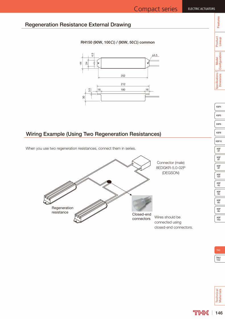
146
ELECTRIC ACTUATORSCompact series
Pro
duc
t Li
neup
Mod
el
Con
figur
atio
nSp
ecifi
catio
ns /
Dim
ensi
ons
Tec
hn
ica
l M
ate
ria
ls
TNU/TJU
KSF8
KSF4
KSF5
KSF6
KSF 10T
KSF10
KSF 5T
KSF 6T
KSF 8T
KSF 10U
KSF 4U
KSF 5U
KSF 6U
KSF 8U
THC
Fea
ture
s
ELECTRIC ACTUATORSCompact series
16
4.5
202
180
212
16 3.5
3024
4.5
44
RH150 (90W, 100Ω) / (90W, 50Ω) common
Regeneration Resistance External Drawing
Wiring Example (Using Two Regeneration Resistances)
Closed-end connectors
Regeneration resistance
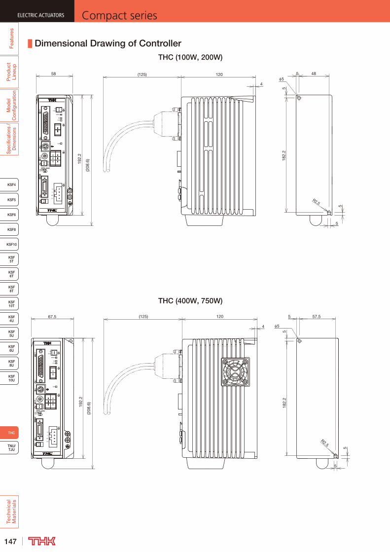
147
ELECTRIC ACTUATORS Compact seriesP
rod
uct
Line
upM
odel
C
onfig
urat
ion
Spec
ifica
tions
/ D
imen
sion
sTe
ch
nic
al
Ma
teri
als
KSF8
KSF4
KSF5
KSF6
KSF 10T
KSF10
KSF 5T
KSF 6T
KSF 8T
KSF 10U
KSF 4U
KSF 5U
KSF 6U
KSF 8U
TNU/TJU
THC
Fea
ture
sELECTRIC ACTUATORS Compact series
Dimensional Drawing of ControllerTHC (100W, 200W)
DBKOFF
6
8
5
0
7
BE
3
2
6CN
CN
7CN
3CN
1
GA
91
CF D
P5C
ALM
GB
AUTO
BRKOFF
MANU
P5P
P24E
SV/
CHAR
P24B
BRKOFF
P15P
ID2
CN9
L2C
CN8
CN4
L1C
CN5
4
A
EM
L1
L2
GB
CN
EM
CN
182.
25
5 4858
5
5
R2.5
192.
2
(208
.6)
5120
4
(125)
CN
EM
CN
GB
L2
L1
EM
A
4
5CN
L1C
4CN
8CN
L2C
9CN
2ID
P15P
BRKOFF
P24B
CHAR
SV/
P24E
P5P
MANU
OFFBRK
AUTO
GB
ALM
P5C
DF C
1 9
GA
1
CN3
CN7
CN
CN6
2
3
E B
7
0
5
8
6
OFFDBK
5
5
518
2.2
57.567.5
192.
2
5
5
R2.5
(208
.6)
120
4
(125)
THC (400W, 750W)
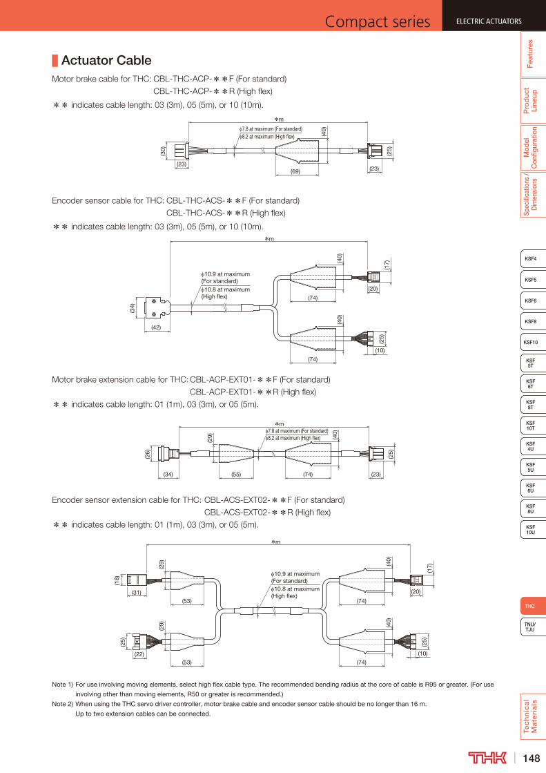
148
ELECTRIC ACTUATORSCompact series
Pro
duc
t Li
neup
Mod
el
Con
figur
atio
nSp
ecifi
catio
ns /
Dim
ensi
ons
Tec
hn
ica
l M
ate
ria
ls
TNU/TJU
KSF8
KSF4
KSF5
KSF6
KSF 10T
KSF10
KSF 5T
KSF 6T
KSF 8T
KSF 10U
KSF 4U
KSF 5U
KSF 6U
KSF 8U
THC
Fea
ture
s
ELECTRIC ACTUATORSCompact series
Actuator Cable****
***m
(69) (23)
(25)
7.8 at maximum (For standard)8.2 at maximum (High flex) (4
0)
(30)
(23)
****
**
(17)
(20)
(42)
(34)
*m
(25)
(10)
10.9 at maximum (For standard)10.8 at maximum
(High flex)
(40)
(74)
(74)
(40)
****
**
(40)
(34)
(26)
(29)
*m
(23)(74)
(25)
7.8 at maximum (For standard)8.2 at maximum (High flex)
(55)
****
**
(40)
(40)
(17)
(20)
*m
(25)
(10)
10.9 at maximum (For standard)10.8 at maximum
(High flex)(74)
(74)
(25)
(22)
(53)
(29)
(18)
(31)
(53)
(29)
Note 1) For use involving moving elements, select high flex cable type. The recommended bending radius at the core of cable is R95 or greater. (For use
involving other than moving elements, R50 or greater is recommended.)
Note 2) When using the THC servo driver controller, motor brake cable and encoder sensor cable should be no longer than 16 m.
Up to two extension cables can be connected.
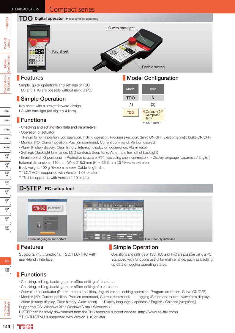
149
ELECTRIC ACTUATORS Compact seriesP
rod
uct
Line
upM
odel
C
onfig
urat
ion
Spec
ifica
tions
/ D
imen
sion
sTe
ch
nic
al
Ma
teri
als
KSF8
KSF4
KSF5
KSF6
KSF 10T
KSF10
KSF 5T
KSF 6T
KSF 8T
KSF 10U
KSF 4U
KSF 5U
KSF 6U
KSF 8U
TNU/TJU
THC
Fea
ture
sELECTRIC ACTUATORS Compact series
D-STEP PC setup tool
Key sheet
Enable switch
Three languages supported User-friendly interface
Functions
Functions
Features
Features
Simple Operation
Simple Operation
LC with backlight
Model Configuration
Model Type
TDO - N
(1) (2)
TDO N: Category 2 1
Compliant Type
1 ISO 13849-1
TDO Digital operator Please arrange separately
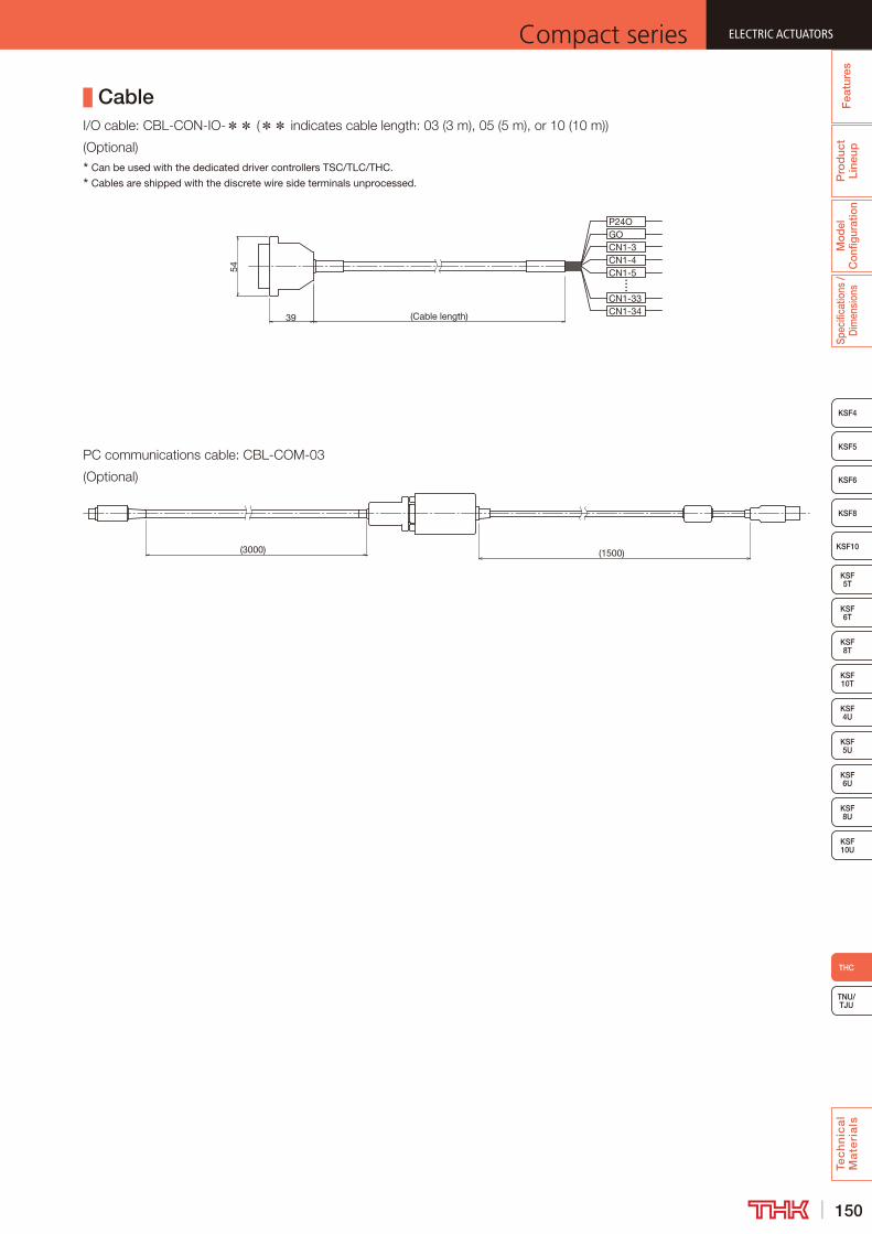
150
ELECTRIC ACTUATORSCompact series
Pro
duc
t Li
neup
Mod
el
Con
figur
atio
nSp
ecifi
catio
ns /
Dim
ensi
ons
Tec
hn
ica
l M
ate
ria
ls
TNU/TJU
KSF8
KSF4
KSF5
KSF6
KSF 10T
KSF10
KSF 5T
KSF 6T
KSF 8T
KSF 10U
KSF 4U
KSF 5U
KSF 6U
KSF 8U
THC
Fea
ture
s
ELECTRIC ACTUATORSCompact series
Cable** **
Can be used with the dedicated driver controllers TSC/TLC/THC.
Cables are shipped with the discrete wire side terminals unprocessed.
(Cable length)
54
39
P24OGOCN1-3CN1-4CN1-5
CN1-33CN1-34
(3000) (1500)
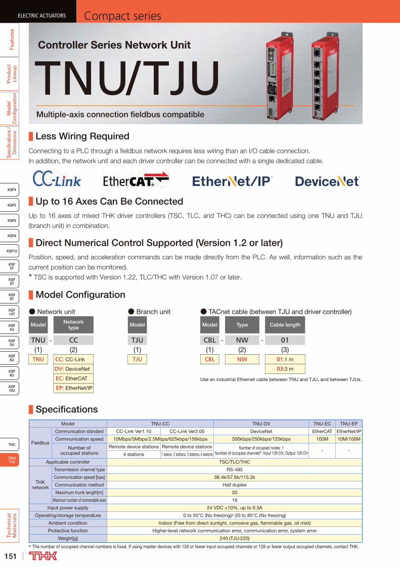
151
ELECTRIC ACTUATORS Compact seriesP
rod
uct
Line
upM
odel
C
onfig
urat
ion
Spec
ifica
tions
/ D
imen
sion
sTe
ch
nic
al
Ma
teri
als
KSF8
KSF4
KSF5
KSF6
KSF 10T
KSF10
KSF 5T
KSF 6T
KSF 8T
KSF 10U
KSF 4U
KSF 5U
KSF 6U
KSF 8U
Fea
ture
sELECTRIC ACTUATORS Compact series
TNU/TJU
THC
ELECTRIC ACTUATORS Compact series
Model Configuration
Specifications
Less Wiring Required
Direct Numerical Control Supported (Version 1.2 or later)
● Network unit
Model Network type
TNU - CC(1) (2)
TNU CC: CC-Link
DV: DeviceNet
EC: EtherCAT
EP: EtherNet/IP
● TACnet cable (between TJU and driver controller)
Model Type Cable length
CBL - NW - 01(1) (2) (3)CBL NW 01:1 m
03:3 m
● Branch unit
Model
TJU(1)TJU
TNU/TJUMultiple-axis connection fieldbus compatible
Controller Series Network Unit
Use an industrial Ethernet cable between TNU and TJU, and between TJUs.
Up to 16 Axes Can Be Connected
Model TNU-CC TNU-DV TNU-EC TNU-EP
Fieldbus
Communication standard CC-Link Ver1.10 CC-Link Ver2.00 DeviceNet EtherCAT EtherNet/IP
Communication speed 10Mbps/5Mbps/2.5Mbps/625kbps/156kbps 500kbps/250kbps/125kbps 100M 10M/100M
Number of occupied stations
Remote device stations Remote device stations Number of occupied nodes: 1Number of occupied channels : Input 128 CH, Output 128 CH - -
4 stations 1 station, 2 stations, 3 stations, 4 stations
Applicable controller TSC/TLC/THC
THK network
Transmission channel type RS-485
Communication speed [bps] 38.4k/57.6k/115.2k
Communication method Half duplex
Maximum trunk length[m] 20
Maximum number of connectable axes 16
Input power supply 24 VDC ±10%, up to 0.3A
Operating/storage temperature 0 to 55°C (No freezing)/-20 to 85°C (No freezing)
Ambient condition Indoor (Free from direct sunlight, corrosive gas, flammable gas, oil mist)
Protective function Higher-level network communication error, communication error, system error
Weight[g] 240 (TJU:220)
The number of occupied channel numbers is fixed. If using master devices with 128 or fewer input occupied channels or 128 or fewer output occupied channels, contact THK.
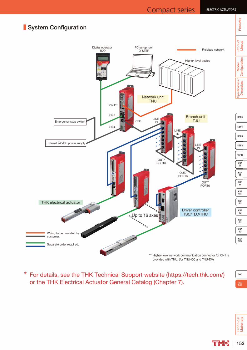
152
ELECTRIC ACTUATORSCompact series
Pro
duc
t Li
neup
Mod
el
Con
figur
atio
nSp
ecifi
catio
ns /
Dim
ensi
ons
Tec
hn
ica
l M
ate
ria
ls
KSF8
KSF4
KSF5
KSF6
KSF 10T
KSF10
KSF 5T
KSF 6T
KSF 8T
KSF 10U
KSF 4U
KSF 5U
KSF 6U
KSF 8U
Fea
ture
s
ELECTRIC ACTUATORSCompact series
TNU/TJU
THC
ELECTRIC ACTUATORSCompact series
KSF8
KSF6
KSF10
KSF5T
KSF6T
KSF8T
Branch unit TJU
Network unit TNU
Up to 16 axes
Higher-level device
CN1 1
LINE IN
OUT/PORT6
OUT/PORT6
OUT/PORT6
Driver controllerTSC/TLC/THC
Digital operator TDO
PC setup tool D-STEP
LINE IN
LINE IN
CN2
CN4
CN3Emergency stop switch
External 24 VDC power supply
THK electrical actuator
Fieldbus network
Wiring to be provided by customer.
Separate order required.
1 Higher-level network communication connector for CN1 is provided with TNU. (for TNU-CC and TNU-DV)
System Configuration
For details, see the THK Technical Support website (https://tech.thk.com/) or the THK Electrical Actuator General Catalog (Chapter 7).

153
ELECTRIC ACTUATORS Compact seriesP
rod
uct
Line
upM
odel
C
onfig
urat
ion
Spec
ifica
tions
/ D
imen
sion
s
KSF8
KSF4
KSF5
KSF6
KSF 10T
KSF10
KSF 5T
KSF 6T
KSF 8T
KSF 10U
KSF 4U
KSF 5U
KSF 6U
KSF 8U
TNU/TJU
Fea
ture
sELECTRIC ACTUATORS Compact series
Tec
hn
ica
l M
ate
ria
ls
THC
ELECTRIC ACTUATORS Compact series
KSF technical materials
Motor Selection
Model ConfigurationActuator Ball screw
Model Stroke [mm] Lead [mm] Shaft diameter [mm] Shaft length [mm] Shaft end diameter [mm]
KSF4
5010 10
257 6h7
900 1107 50
16 10257
6h7900 1107
KSF5
5010 13
274 8h7
900 1124 50
20 13274
8h7900 1124
KSF6
5020 15
328 9h7
1300 1578 50
30 15328
9h71300 1578
KSF8
10020 20
446 12h7
1500 1846 100
40 20446
12h71500 1846
KSF10
10025 25
48515h7
1500 1885100
50 25485
15h71500 1885
Weight of moving element
ModelWeight of moving element [kg]
Fully enclosed Open Cover Top coverKSF4 0.4 0.3 -KSF5 0.5 0.4 0.5 (0.6)KSF6 1.0 0.8 1.0 (1.4)KSF8 2.1 1.9 2.4 (3.5)KSF10 4.0 3.3 6.2
( ) shows the value when option "F" is selected.
Permissible input torque
ModelPermissible input torque [N·m]
Direct motor coupling Motor wrapKSF4 1.2 1.1KSF5 1.8 1.1KSF6 3.1 2.2KSF8 7.1 4.5KSF10 15.5 8.4
Recommended CouplingRecommended coupling (flat spring type)
Model Type Inertial moment [kg·cm2]
KSF4
SFC-020DA2 (Miki Pulley Co., LTD.)
0.034
XBW-25C2 (Nabeya Bi-tech Kaisha)
0.023
KSF5
SFC-020DA2 (Miki Pulley Co., LTD.)
0.034
XBW-25C2 (Nabeya Bi-tech Kaisha)
0.023
KSF6
SFC-030DA2 (Miki Pulley Co., LTD.)
0.094
XBW-34C3 (Nabeya Bi-tech Kaisha)
0.090
KSF8
SFC-030DA2 (Miki Pulley Co., LTD.)
0.116
XBW-34C3 (Nabeya Bi-tech Kaisha)
0.090
KSF10
SFC-040DA2 (Miki Pulley Co., LTD.)
0.430
XBW-44C2 (Nabeya Bi-tech Kaisha)
0.350
Timing PulleyTiming Pulley (2 pieces total)
Actuator modelInertial moment
[kg·cm2]KSF4R 0.028KSF5R 0.028KSF6R 0.398KSF8R 0.497KSF10R 2.061

154
ELECTRIC ACTUATORSCompact series
Pro
duc
t Li
neup
Mod
el
Con
figur
atio
nSp
ecifi
catio
ns /
Dim
ensi
ons
TNU/TJU
KSF8
KSF4
KSF5
KSF6
KSF 10T
KSF10
KSF 5T
KSF 6T
KSF 8T
KSF 10U
KSF 4U
KSF 5U
KSF 6U
KSF 8U
Fea
ture
s
ELECTRIC ACTUATORSCompact series
Tec
hn
ica
l M
ate
ria
ls
THC
ELECTRIC ACTUATORSCompact series
Load Ratings in All Directions and Static Permissible Moment
●
●
●
Equivalent Load (LM Guide Unit)
PE = PR(PL)+ PT
PE : Equivalent load [N] · Radial direction · Reverse radial direction · Lateral directionsPR : Radial load [N]PL : Reverse radial load [N]PT : Lateral load [N]
ModelItem
KSF4 KSF5 KSF6 KSF8 KSF10
KSF4-10 KSF4-16 KSF5-10 KSF5-20 KSF6-20 KSF6-30 KSF8-20 KSF8-40 KSF10-25 KSF10-50
LM guide Unit
Basic dynamic load rating C [N] 6,400 10,200 17,400 32,400 58,500
Basic static load rating C0[N] 12,900 17,900 33,000 63,500 103,700
Ball screw Unit
Basic dynamic load rating Ca[N] 2,860 1,850 3,350 2,150 3,400 3,230 4,030 3,750 6,650 4,150
Basic static load rating C0a[N] 5,110 3,420 6,600 4,470 8,070 6,570 10,540 8,870 21,050 11,170
Screw shaft diameter [mm] 10 13 15 20 Φ25
Ball screw lead [mm] 10 16 10 20 20 40 20 40 25 50
Bearing Unit (Fixed side)
Axial direction
Basic dynamic load rating Ca[N] 2,930 6,100 6,650 7,600 13,700
Static permissible load P0a[N] 2,140 3,100 3,250 4,000 5,830
Radial loadPR
Reverse radial loadPL
PT
Lateral loadPT
Lateral load
ModelStatic Permissible Moment
ModelStatic Permissible Moment
MA MB MC MA MB MC
KSF4 103 103 58 KSF6U 355 203 152KSF4U 103 95 58 KSF8 730 437 387KSF5 147 147 149 KSF8T 324 (730) 253 (425) 265 (503)
KSF5T 103 (147) 61 (137) 80 (149) KSF8U 730 414 277KSF5U 147 107 89 KSF10 1,049 712 671KSF6 330 216 188 KSF10T 1,259 949 787
KSF6T 150 (266) 124 (252) 139 (253) KSF10U 1,259 775 504
( ) shows the value for sub-table iron specifications.
Units: N·m
MA
MB MC
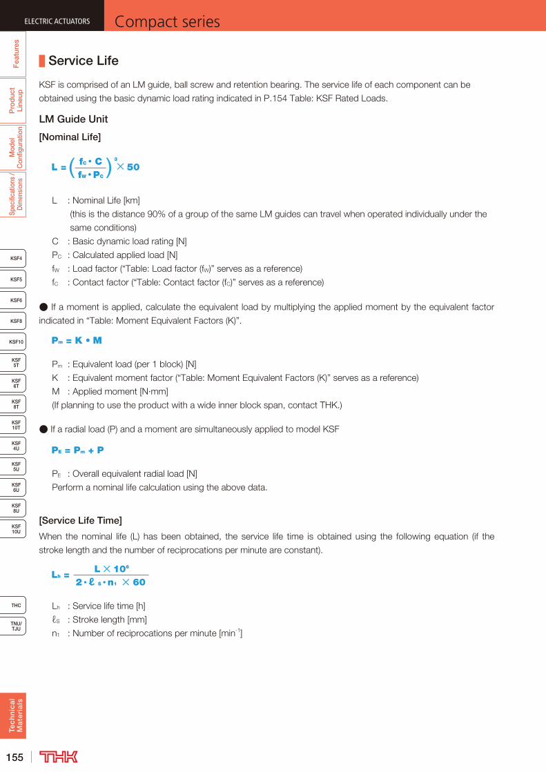
155
ELECTRIC ACTUATORS Compact seriesP
rod
uct
Line
upM
odel
C
onfig
urat
ion
Spec
ifica
tions
/ D
imen
sion
s
KSF8
KSF4
KSF5
KSF6
KSF 10T
KSF10
KSF 5T
KSF 6T
KSF 8T
KSF 10U
KSF 4U
KSF 5U
KSF 6U
KSF 8U
TNU/TJU
Fea
ture
sELECTRIC ACTUATORS Compact series
Tec
hn
ica
l M
ate
ria
ls
THC
ELECTRIC ACTUATORS Compact series
Service Life
LM Guide Unit
[Nominal Life]
fW PC
L = 3
50fC C
●
Pm = K M
●
PE = Pm + P
E
[Service Life Time]
2 ℓ S n1 60Lh =
L 106
ℓ
1
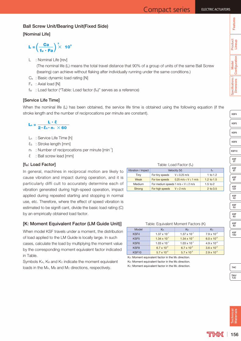
156
ELECTRIC ACTUATORSCompact series
Pro
duc
t Li
neup
Mod
el
Con
figur
atio
nSp
ecifi
catio
ns /
Dim
ensi
ons
TNU/TJU
KSF8
KSF4
KSF5
KSF6
KSF 10T
KSF10
KSF 5T
KSF 6T
KSF 8T
KSF 10U
KSF 4U
KSF 5U
KSF 6U
KSF 8U
Fea
ture
s
ELECTRIC ACTUATORSCompact series
Tec
hn
ica
l M
ate
ria
ls
THC
ELECTRIC ACTUATORSCompact series
Ball Screw Unit/Bearing Unit(Fixed Side)
[Nominal Life]
CaL = 3
106
fW Fa
[Service Life Time]
L ℓLh =
2 ℓS n1 60
1
[fW: Load Factor]Vibration / Impact Velocity (V) fw
Tiny For tiny speeds V ≤ 0.25 m/s 1 to 1.2
Weak For low speeds 0.25 m/s < V ≤ 1 m/s 1.2 to 1.5
Medium For medium speeds 1 m/s < V ≤ 2 m/s 1.5 to 2
Strong For high speeds V > 2 m/s 2 to 3.5
[K: Moment Equivalent Factor (LM Guide Unit)]Model KA KB KC
KSF4 1.37 x 10⁻¹ 1.37 x 10⁻¹ 7.9 x 10⁻²
KSF5 1.34 x 10⁻¹ 1.34 x 10⁻¹ 6.0 x 10⁻²
KSF6 1.03 x 10⁻¹ 1.03 x 10⁻¹ 4.9 x 10⁻²
KSF8 6.7 x 10⁻² 6.7 x 10⁻² 3.6 x 10⁻²
KSF10 5.7 x 10⁻² 5.7 x 10⁻² 2.9 x 10⁻²
KA: Moment equivalent factor in the MA direction.
KB: Moment equivalent factor in the MB direction.
KC: Moment equivalent factor in the MC direction.

157
ELECTRIC ACTUATORS Compact series
KSF8
KSF4
KSF5
KSF6
KSF 10T
KSF10
KSF 5T
KSF 6T
KSF 8T
KSF 10U
KSF 4U
KSF 5U
KSF 6U
KSF 8U
TNU/TJU
THC
Fea
ture
sP
rod
uct
Line
upM
odel
C
onfig
urat
ion
Spec
ifica
tions
/ D
imen
sion
sTe
ch
nic
al
Ma
teri
als
MEMO
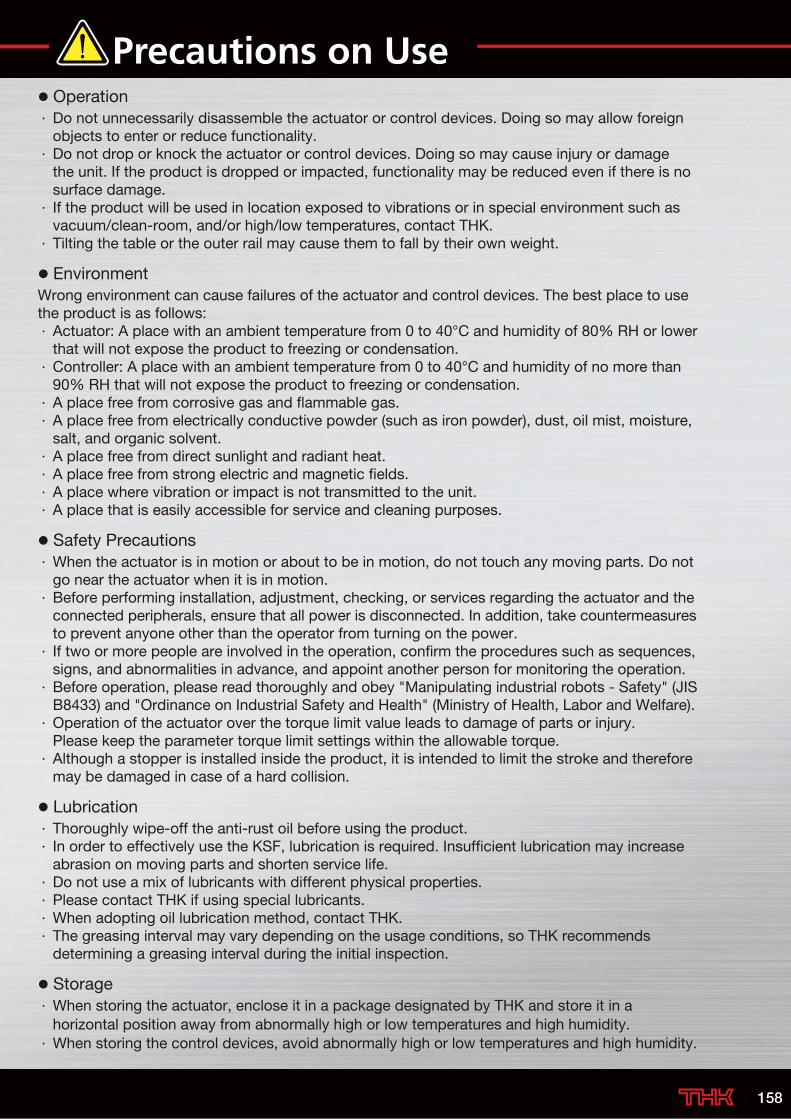
Precautions on Use Operation · Do not unnecessarily disassemble the actuator or control devices. Doing so may allow foreign objects to enter or reduce functionality.
· Do not drop or knock the actuator or control devices. Doing so may cause injury or damage the unit. If the product is dropped or impacted, functionality may be reduced even if there is no surface damage.
· If the product will be used in location exposed to vibrations or in special environment such as vacuum/clean-room, and/or high/low temperatures, contact THK.
· Tilting the table or the outer rail may cause them to fall by their own weight.
EnvironmentWrong environment can cause failures of the actuator and control devices. The best place to use the product is as follows: · Actuator: A place with an ambient temperature from 0 to 40°C and humidity of 80% RH or lower that will not expose the product to freezing or condensation.
· Controller: A place with an ambient temperature from 0 to 40°C and humidity of no more than 90% RH that will not expose the product to freezing or condensation.
· A place free from corrosive gas and flammable gas. · A place free from electrically conductive powder (such as iron powder), dust, oil mist, moisture, salt, and organic solvent.
· A place free from direct sunlight and radiant heat. · A place free from strong electric and magnetic fields. · A place where vibration or impact is not transmitted to the unit. · A place that is easily accessible for service and cleaning purposes.
Safety Precautions · When the actuator is in motion or about to be in motion, do not touch any moving parts. Do not go near the actuator when it is in motion.
· Before performing installation, adjustment, checking, or services regarding the actuator and the connected peripherals, ensure that all power is disconnected. In addition, take countermeasures to prevent anyone other than the operator from turning on the power.
· If two or more people are involved in the operation, confirm the procedures such as sequences, signs, and abnormalities in advance, and appoint another person for monitoring the operation.
· Before operation, please read thoroughly and obey "Manipulating industrial robots - Safety" (JIS B8433) and "Ordinance on Industrial Safety and Health" (Ministry of Health, Labor and Welfare).
· Operation of the actuator over the torque limit value leads to damage of parts or injury. Please keep the parameter torque limit settings within the allowable torque.
· Although a stopper is installed inside the product, it is intended to limit the stroke and therefore may be damaged in case of a hard collision.
Lubrication · Thoroughly wipe-off the anti-rust oil before using the product. · In order to effectively use the KSF, lubrication is required. Insufficient lubrication may increase abrasion on moving parts and shorten service life.
· Do not use a mix of lubricants with different physical properties. · Please contact THK if using special lubricants. · When adopting oil lubrication method, contact THK. · The greasing interval may vary depending on the usage conditions, so THK recommends determining a greasing interval during the initial inspection.
Storage · When storing the actuator, enclose it in a package designated by THK and store it in a horizontal position away from abnormally high or low temperatures and high humidity.
· When storing the control devices, avoid abnormally high or low temperatures and high humidity.
158

Compact Series KSF
All rights reserved.
� LM Guide, and are registered trademarks of THK CO., LTD.� The actual products may differ from the pictures and photographs in this catalog.
� Outward appearances and specifications are subject to change without notification for the purpose of improvement.
� Although great care has been taken in the production of this catalog, THK will not take any responsibility for damage resulting from typographical errors or omissions.
� In exporting our products and technology, or selling them for the purpose of export, THK has a basic policy of observing laws relating to foreign exchange, trade and other laws.
For export of THK products as single items, please contact THK in advance.
©THK CO., LTD. 201608000 E27 Printed in Japan
Head Office 3-11-6 Nishigotanda, Shinagawa-ku, Tokyo 141-8503 JAPANInternational Sales Department Phone:+81-3-5434-0351 Fax:+81-3-5434-0353
NORTH AMERICATHK America,Inc.
HEADQUARTERSPhone:+1-847-310-1111 Fax:+1-847-310-1271CHICAGO OFFICEPhone:+1-847-310-1111 Fax:+1-847-310-1182NORTH EAST OFFICEPhone:+1-631-244-1565 Fax:+1-631-244-1565ATLANTA OFFICEPhone:+1-770-840-7990 Fax:+1-770-840-7897LOS ANGELES OFFICEPhone:+1-949-955-3145 Fax:+1-949-955-3149SAN FRANCISCO OFFICEPhone:+1-925-455-8948 Fax:+1-925-455-8965DETROIT OFFICEPhone:+1-248-858-9330 Fax:+1-248-858-9455TORONTO OFFICEPhone:+1-905-820-7800 Fax:+1-905-820-7811
SOUTH AMERICATHK BRAZIL INDUSTRIA E COMERCIO LTDA.
Phone:+55-11-3767-0100 Fax:+55-11-3767-0101EUROPETHK GmbH
DÜSSELDORF OFFICEPhone:+49-2102-7425-0 Fax:+49-2102-7425-299
EUROPEAN HEADQUARTERSPhone:+49-2102-7425-555 Fax:+49-2102-7425-556
U.K. OFFICEPhone:+44-1384-47-1550 Fax:+44-1384-47-1551
Global site : http://www.thk.com/
STUTTGART OFFICEPhone:+49-7141-4988-500 Fax:+49-7141-4988-888
TURKEY OFFICEPhone:+90-216-362-4050 Fax:+90-216-569-7150
MOSCOW OFFICEPhone:+7-495-649-80-47 Fax:+7-495-649-80-44
SWEDEN OFFICEPhone:+46-8-445-7630 Fax:+46-8-445-7639 AUSTRIA OFFICEPhone:+43-7229-51400 Fax:+43-7229-51400-79SPAIN OFFICEPhone:+34-93-652-5740 Fax:+34-93-652-5746
EINDHOVEN OFFICETHK Europe B.V.
THK France S.A.S.Phone:+31-040-290-9500 Fax:+31-040-290-9599
PARIS OFFICEPhone:+33-1-7425-3800 Fax:+33-1-7425-3799
PRAGUE OFFICEPhone:+420-2-41025-100 Fax:+420-2-41025-199
SHANGHAI OFFICEPhone:+86-21-6219-3000 Fax:+86-21-6219-9890BEIJING OFFICEPhone:+86-10-8441-7277 Fax:+86-10-6590-3557CHENGDU OFFICEPhone:+86-28-8526-8025 Fax:+86-28-8525-6357GUANGZHOU OFFICEPhone:+86-20-8523-8418 Fax:+86-20-3801-0456
CHINATHK (CHINA) CO.,LTD.
HEADQUARTERSPhone:+86-411-8733-7111 Fax:+86-411-8733-7000
TAI ANTHK TAIWAN CO.,LTD.
TAIPEI HEAD OFFICEPhone:+886-2-2888-3818TAICHUNG OFFICEPhone:+886-4-2359-1505TAINAN OFFICEPhone:+886-6-289-7668
OREASEOUL REPRESENTATIVE OFFICE
Phone:+82-2-3468-4351SINGAPORETHK LM System Pte. Ltd.
THK (SHANGHAI) CO.,LTD.Phone:+86-21-6275-5280 Fax:+86-21-6219-9890
Fax:+886-2-2888-3819
Fax:+886-4-2359-1506
THK India Pvt. Ltd.HEADQUARTERS & Bangalore BranchPhone:+91-80-2340-9934Pune BranchPhone:+91-20-4120-8742
Fax:+91-80-2340-9937
Chennai BranchPhone:+91-44-4042-3132Ahmedabad BranchPhone:+91-79-6134-4925Delhi BranchPhone:+91-12-4676-8695
Fax:+886-6-289-7669
Fax:+82-2-3468-4353
Fax:+65-6884-5550
INDIA
Phone:+65-6884-5500THAI ANDTHK RHYTHM(THAILAND) CO., LTD. LM System Division
Bangkok BranchPhone:+66-2751-3001 Fax:+66-2751-3003
XIAN OFFICEPhone:+86-29-8834-1712 Fax:+86-29-8834-1710
ITALY OFFICEPhone:+39-02-9901-1801 Fax:+39-02-9901-1881
SHENZHEN OFFICEPhone:+86-755-2642-9587 Fax:+86-755-2642-9604
![High-temperature LM Guide Series - THK · 2010-06-04 · • 3 • Precautions on the Use of the THK High-temperature LM Guide [Operating Temperature of High-temperature LM Guide]](https://img.pdfslide.us/doc/110x75/5e737b81d316ce3fb11f5599/high-temperature-lm-guide-series-thk-2010-06-04-a-3-a-precautions-on-the.jpg)