Embed Size (px)
Citation preview

- 253 shy
New Collider Detectors and PhysicS Capabilities
- 254 shy
It-IPROVEHENT PROGRAMHE OF THE UA2 DETECTOR
The UA2 Collaboration
Bern - Cambridge - CERN - Milan - Orsay (LAL)
Pavia - Pisa - Sac lay
Presented by Jean-t-larc GAILLARD
Laboratoire de llAccelerateur Lineaire
91405 Orsay France
1 INTRODUCTION
The UA2 experiment took its first data in November 1981 and has been
operating smoothly since then The very successful performance of the SppS
collider has given us the opportunity to collect a large amount of very
fruitful data [1-7]
After a long shut-down in 1986 the SppS collider will resume operation
with a substantially higher luminosity than presently available The recently
approved Antiproton Collector (ACOL) should allow for a total integrated
luminosity of nearly 10 pb- 1 by the end of 1989 In order to make the best
use of the increased luminosity in terms of physics results the performance of
the present UA2 detector has to be simultaneously improved
The emphasis placed in the present design [891011] on high mass final
states containing parton jets electrons and neutrinos has proven to be an
excellent choice mostly because of the low transverse momentum usually given
to spectator particles (not directly involved in the short distance collision
of interest) As a result of the high quality of the UA2 calorimetry (fine
segmentation tower geometry) we were able to give the first evidence for jet
production at the Collider and for a resolved ZO ~ e+e-r decay The absence
of magnetic field in the central region turned out to be a good choice since
- 255 shy
it does not significantly deteriorate the electron identification power as
soon as the electron transverse momentum exceeds ~ 25 GeVIc and does not
preclude competitive performance on the major physics issues Similarly the
lack of muon detection dictated by the desire to avoid the use of bulky
equipment such as thick absorbers and large magnetic field volumes does not
substantially impair the physics output of the UA2 detector It is true that
the restriction of lepton detection to electrons and neutrinos precludes their
observation amid jet fragments while significantly better results might be
achieved with muons
We do not propose therefore to alter the maj or des ign opt ions of the
present UA2 detector but rather to improve its performance in the domains
where it is already effective the detection of electrons neutrinos and
hadron jets
The importance of a good missing transverse energy detection capability
was not fully recognised when UA2 was des igned in 1978 It now appears
essential not only to study final states containing an electron-neutrino
pair but also to search for possible supersymmetric particles ultimately
expected to decay into undetected photinos Dead regions such as the magnet
coils of the forward UA2 spectrometers and the lack of coverage below 20deg
preclude an accurate missing transverse energy measurement For example a
twojet event having a mass of ~ 50 GeVc 2 is det~cted as a single jet event
in ~ 2 of the cases the other jet escaping detection
The solid angle over which a hermetic coverage is necessary depends upon
the mass range to be explored a Monte Carlo study indicates that a coverage
down to ~ 10deg from the beam line should be adequate We propose therefore to
extend down to this angle the transverse energy flow measurement presently
performed in the central calorimeter by replacing the forward spectrometers
with segmented calorimeter end caps In doing so we shall lose the ability to
measure particle charges in this region but we consider the gain of improving
on neutrino detection to be more important
The ear ly discoveries of the Wplusmn and Z0 bosons through their ev and emiddot eshy
decay modes illustrate well the power of electron identification as a mean of
selecting interesting events among the bulk of hadronic collisions In the
- 256 shy
present VA2 detector jets can fake electrons at a level of the order of 10- 5
of the inclusive jet yield While this background is much lower than the
electron signal from Wand ZO decays it is higher than the expected signal
from semileptonic decays of t-quarks (m(t) lt 40 GeV) by about one order of
magnitude An improvement over the present situation implies a simultaneous
discrimination against the two major types of misidentified electrons
converted photons from nO decays and unresolved nO-n-+ pairs
2 CALORIMETER END CAPS
In order to implement the transverse energy flow measurement down to small
angles we propose to replace the present forward spectrometers with segmented
calorimeter end caps This approximately triples the longitudinal phase space
coverage of the present central calorimeter and improves accordingly the
ability of our apparatus to detect hadron jets and to provide an accurate
measurement of missing transverse energy The design provides for electron
identification down to = 20deg with a rejection power against background similar
to that achieved in the central region
We have studied the expected performance in relation to the measurement of
transverse energy by simulating with a Monte Carlo programme the r~sponse of
the detector to a set of two-jet events generated with ISAJET [12] The
detector coverage extends over a range of polar angles between 8 and m 180deg - 8 Figure 1 shows the dependence upon 8 of the average missingm m transverse energy under the assumption that one of the two jets has
PoL jetgt 25 GeVc and 20deg lt 8 t lt 160deg Figure 2 shows the distribution ofJe
the fraction of events having a missing transverse energy in excess of 20 GeV
f 20 A contribution of = 10- 3 from events containing semi leptonic decays of
heavy flavours remains in the case of an ideal detector (8 = 0 no energym
measurement errors but no muon nor neutrino detection) For a realistic
detector f levels off at = 10- 2 for any am lt 10deg one order of magnitude20 lower than in the present design The results shown in fig1 and 2 are
illustrative of the performance expected in the kinematical domain of
practical interest and suggest to extend the end cap coverage down to
a = 10deg This implies the instrumentation of the forward cones down to m a = 5deg to allow for a reasonable margin around the actual fiducial volume m
- 257 shy
The general layout is illustrated in fig3 The calorimeter end caps are
shown without their movable support structure which will allow recessing the
calorimeters from the beam pipe during machine developments with high
radiation levels
Each end cap is divided into sectors subtending 6~ = 30deg in azimuth The
absorber plates in each sector are continuous over the whole polar angle
region 56deg lt a lt 45deg the segmentation into cells (towers) is defined by the
scintillator plates The wavelength shifter (WLS) plates collect the light of
each cell at about constant azimuth with a segmentation of 6~ = 15deg for
a gt 127deg and 6~ == 30deg for a lt 127deg Each tower consists of an
electromagnetic and an hadronic calorimeter compartments For both
compartments the readout will be made by WLS plates on opposite sides of each
cell The light is channeled via a twisted strip light guide optics onto
Philips XP2012 B photomultipliers
The parameters of the end cap calorimeter are given in table 1
3 UPGRADED VERTEX DETECTOR
31 Introduction
Moving outwards from the interaction region the main components of the new
design include (figure 4)
i) A small diameter beryllium vacuum chamber to be installed in 1985
ii) A jet chamber vertex detector (JVD) providing an accurate
measurement of the longitudinal and transverse positions of the
event vertex
iii) A matrix of silicon counters with the double purpose of measuring
ionisation and helping in pattern recognition
- 258 shy
iv) A pair of transition radiation detectors (TRD) providing an
additional rejection factor of at least an order of magnitude
against fake electrons
v) A multilayer scintillating fibre detector (SFD) for tracking and for
measuring early electromagnetic showers developing after a 15
radiation length thick converter
The new design is expected to substantially reduce the two most
significant sources of backgrounds faking electrons converted photons from n D
decays and narrow nD-charged hadron pairs (overlaps)
The insertion of a transition radiation detector a key feature of the new
design is at the price of dedicating to it a major fraction of the space
available in the central region of UA2 (about half of the radial range) In
turn this implies very efficient and compact tracking devices fitting in the
remaining available space the JVD and silicon array in the inner region the
SFD in the outer region Both have the ability to measure track segments In
addition the outer cathodes of the TRD chambers are equipped with strips to
help match the two regions
While inner tracking provides direct localisation in space (charge
division on the JVD wires and silicon pads) the SFD measures three
stereoscopic projections The stereo angle has been chosen small enough to
reduce ghost tracks to a satisfactory level while retaining sufficient
localisation accuracy The outer layers of the SFD act as a preshower counter
thus providing a compact and unified design in the angular range covered by
the central UA2 calorimeter Modifications to the des ign of the extreme
electromagnetic calorimeter cells have been necessary to enlarge the space
available for the UA2 central detector
The overall dimensions of the UA2 central detector have been defined to
match the geometry of the central and end cap calorimeters and to provide
tracking capability over the solid angle in which electrons are to be
identified This implies complete coverage in azimuth (t) and a polar angle
(8) coverage from 25 0 to 155 0 allowing for vertex excursions of plusmn200 mm along
the beam direction (z) This latter constraint is forced on us by the geometry
- 259 shy
of the central calorimeter While it is perfectly adequate in the present mode
of Collider operation it would become too small if longer bunches were used as
the result of a modification of the RF system
The UA2 central detector will be supported from the central calorimeter
and the various cables (=600 cm 2 in cross-section) connected to its end plates
are channelled to the UA2 cable-rails through the space between the central
and end-cap calorimeters
32 Jet Chamber Vertex Detector (JVD)
The design of the JVD constrained to fit between the vacuum pipe
(R = 32 mm) and the silicon array (R = 140 mm) is of the jet chamber type in
order to satisfy the following requirements
i) to measure space points in order to minimize ambiguities in the
event reconstruction
ii) to sample at least 12 space points per track with S 150 pm accuracy
in R x t
iii) to separate nearby tracks in projection R x ~t S 1 mm
iv) to provide good accuracy in z both to separate double vertices and
to allow precise extrapolation to the outer tracking devices
v) to minimize photon conversions implying a good transparency
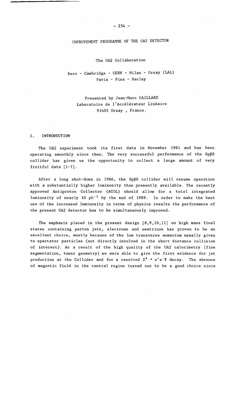
Longitudinal and transverse cross-sections are shown in fig5 The
detector has an outer radius of 135 mm an inner radius of 35 mm and a total
length of 1600 mm (excluding the electronics) The chamber is divided into 16
azimuthal sectors each equipped with 13 (staggered) sense wires 1100 mm long
at 65 mm spacing with guard wires interspersed among them (fig5) Tracks
will be measured down to 8 = 25 0 with allowance for plusmn 200 mm excursions of
the vertex along the beam To minimize the material between the beam and the
- 260 shy
sensitive region only the external cylindrical wall will carry the mechanical
tension of the wires Digitization of the drift time and readout of the z
coordinate by charge division will be provided by the 100 MHz Flash-ADC (FADC)
system developed at CERN by F Bourgeois [13] To enhance two-track
separation capability we plan to operate the chamber with a slow gas (90
CO 2 + 10 Isobutane) at a drift velocity z 1cm~s (EP = 13 kVcmatm)
To improve the accuracy of the track extrapolation to the SFD
(R 400 mm) a cathode readout of the outermost sense wires using 168
cylindrical strips perpendicular to the beam direction measures the
z-coordinate of the avalanches on every sense wire
33 Silicon Array
On a cylinder of radius 140 mm around the beam pipe we intend to construct a
matrix of 432 silicon counters each divided into seven individual readout
channels (3024 in total) This array is immediately outside the JVD It will
be used in conjunction with that detector to
i) reject photon conversions by providing with good granularity a
measurement of the ionisation of charged track~ and
ii) help track reconstructionby providing a space~point measurement
It is intended to install this array before the 1985 data taking period
and it has therefore been designed to be also compatible with the existing
vertex detector
Each silicon counter has a size of 61 x 40 x 03 mml Nine counters are
arranged on each of 48 fibreglass boards Each board covers an azimuthal
interval of 15deg and half the polar angle range By overlapping individual
counters on the board the array has a negligible inactive area On each board
low noise amplifiers are mounted behind the detectors and the signals are
subsequently transferred to the end of the detector via a multi-layer circuit
board Shaping amplifiers track-and-hold circuits and mUltiplexing
- 261 shy
electronics are mounted at the end of each board Each board is enclosed in a
box and mounted on a thin support cylinder
Twelve prototype counters of the final design specification [14] have
been extensively tested and the prototype tests are continuing Tests which
are underway include
i) long-term leakage current tests
RU 106ii) tests of pulse-height resolution using a e-source
iii) the dependence of the above on the applied bias voltage
iv) radiation damage including tests with a lmCi Sro source and with
radiation in the SPS tunnel
Within the limited statistics of present radiation damage tests the
counter deterioration (measured as an increase in leakage current) is
~ 1 nAcm 2 Gray in the UA2 environment this suggests for the present counter
design a maximum tolerable dose of 200 Gray No problem is therefore
expected apart from possible accidental beam losses (the total dose during
the 1983 running period was ~ 3 Gray at the proposed array location)
Typical pulse-height spectra for counters passing our design criteria are
shown in fig6 A rejection factor against photon conversions of 15 to 20
with 90 efficiency is expected
34 Transition Radiation Detector (TRD)
The TRD is inserted in the 210 mm of radial space between the silicon
array and the SFD It is made of two modules each consisting of a lithium
radiator to emit X-rays and a xenon proportional chamber to detect them
Each radiator is cylindrical and has a thickness of 80 mm It contains a
stack of 400 lithium foils 40 ~m thick separated by 160 ~m The spacing is
- 262 shy
maintained by corrugations in the foils The total lithium weight is 50 kg
The average number of photons produced by an electron of energy gt 5 GeV
traversing the radiator at normal incidence and subsequently absorbed in the
xenon chamber is 2 Their average energy is 6 keY
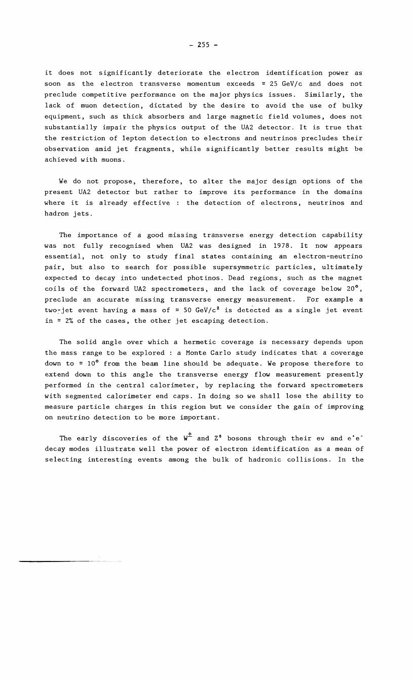
The xenon chambers consist of two layers of gas 10 and 6 mm thick
separated by a grid of wires connected to ground The gas mixture is 70
xenon 30 CO 2 In the first layer a drift velocity of 20 ~mns is obtained
with an electric field of 400 Vcm The second layer is used as an
amplification stage The signal wires are separated by 44 mm and interspersed
with field wires (fig7) The signal wires are at a voltage of 16 kV and the
two cathodes of the amplification stage are grounded This allows the outer
cathode to be made of helical strips from which the charge can be read out
Each module is about 0015 thick in both radiation length and interaction
length
The wires are connected to preamplifiers and the signals are measured in a
100 MHz FADC [13] The strips are connected to preamplifiers and the integral
of the charge induced by the avalanche is measured in ADC s Since the
signals coming from the drift space and the amplification stage arrive at
different times we plan to measure them independently
We have used a computer programme [15] to evaluate the electron detection
efficiency and the rejection against hadrons and to optimize the radiator and
chamber parameters The results of this programme have been compared to real
test measurements They show that a two-module design is more efficient than a
single-module design given the available space Using the cluster counting
method we expect a rejection of a factor 15 against hadrons with an
efficiency of 80 for electrons This performance improves by a factor 3 when
the polar angle of the electron changes from 90deg to 30deg The rejection is of
course degraded when two ion1z1ng particles hit the same wire but the
measurement of the charge induced on the strip will help to recover part of
this loss
- 263 shy
35 Scintillating Fibre Detector (SFD)
Recent developments in scintillating plastic fibres made at Saclay offer
an attractive possibility to construct a compact position detector with good
track reconstruction efficiency and adequate spatial accuracy As emphasized
above compactness is absolutely necessary to provide space within the UA2
apparatus for the TRD The present design of the SFD is based upon
i) extensive tests that we have made with fibres during the second half
of 1984
ii) Monte Carlo studies of the track reconstruction properties using
simulated pp events
iii) measurements on and investigations of the various components
(image intensifiers CCD digitizers) necessary to read and
digitize the fibre information
The SFD whose general layout is shown in fig6 has a radial thickness of 60
mm at an average radius of 410 mm It consists of about 60000 fibres with a
total length of 150 km arranged in seven groups of three layers (triplets)
In each triplet the angles of the fibres with respect to the beam axis are
-a 0 and a for the three layers respectively This provides space
coordinates from three stereoscopic proj ections Within the angular range
covered by the central UA2 calorimeter a converter (1 and 05 radiation
lengths respectively) is inserted in front of each of the two outer triplets
which are thus used as a preshower counter
The choices for the design of the detector are based on the standard
fibres which we have tested They are made of a core of polystyrene doped
with POPOP and butyl-PBD with a thin cladding (=10 ~m) and have a numerical
aperture of 062 These fibres are currently produced by Saclay (STIPE) in
lengths of 600 m with a 1 mm diameter
We plan to view the fibres from one end only and to place a reflector at
the other end We expect on average 91 efficiency per fibre for particles at
e = 90deg For other values of e the average efficiency becomes closer to 100
- 264 shy
A schematic representation of the read_out system is shown in fig8 It is
composed of three parts The light output from the fibres is amplified with a
photon gain of 10 by the image intensifiers (II) The light is then
converted by a charge coupled device (CCD) into a signal which is read by the
digitizer and stored in a memory The photon gain of the II system is chosen
such that the average signal per CCD element (pixel) within the area
corresponding to a fibre hit by a charged particle is ten times larger than
the noise level of the CCD The principle of operation is also indicated in
fig8 The gate of the II system is normally open and information accumulates
in the CCD About 1 ~s after each crossing an external trigger decision (not
using the fibre information) leads to one of the two following sequences
i) no-trigger case a fast-clear pulse is applied to the CCD draining
away the accumulated charge in S 15 ~s The II gate stays open and
new information is collected in the CCDmiddot
ii) trigger case the gate on the II system is closed to prevent
illumination from subsequent pp interactions while reading the CCD
information related to the event associated with the trigger
(=4 ms) When the CGD reading is completed the II gate is reopened
From investigations with several firms it has become clear that three
amplifying stages are necessary to meet our gain specifications a moderate
gain unit a high gain II tube with microchannel plate an other moderate
gain unit The first and the third units are demagnifying the fibers image
The fibre optic window at the exit of the II chain is directly coupled to
a CCD where the light is converted to electrical charges which are stored It
is essential that unwanted information can be cleared off from the device
during the time available between two pp crossings This can be achieved by
using the antiblooming system with which some commercial CCDts are equipped
In collaboration with the manufacturer [16] we have tested the CCD TH7852
which we plan to use and we have found that it can be fast-cleared by
applying a pulse of S 15 ~s duration to the antiblooming input
The CCD TH7852 has an optical area of 58 x 43 mm 2 with 144 x 208
sensitive elements (pixels) Each pixel has an active area of 19 x 30 ~m2 and
- 265 shy
a geometrical area of 28 x 30 pm 2 bull With the demagnification of the II chain
a 1 mrn diameter fibre may illuminate up to about 20 pixels
For events satisfying the trigger requirement the content of each CCD is
read out We consider that pulse height information is useful in pattern
recognition and necessary for the preshower part of the SFD In addition
since in a typical event particle tracks cross == 2 of the fibres the
compaction of data is essential for an efficient and economical utilization of
memory
4 END CAP TRACKING AND PRESHOWER
The compactness of the upgraded VA2 apparatus constrains the tracking and
preshower devices to be confined in a small volume inside the central
calorimeters
Taking into account the accuracy required to localize the shower it turns
out that the choice of proportional tubes with a 1 cm wire spacing using
extruded aluminium profiles allows for compactness and easy large-scale
production A proportional mode of operation is chosen for both devices in
order to cope with high particle densities which could be expected from the
higher luminoSity at the collider and the absence of magnetic field as well
as maintaining the widest possible dynamic range for measuring the total
particle multiplicity in electromagnetic showers In addition analog
measurements allow for better space localization of the electromagnetic shower
by determining the center of gravity of the charge collected in each plane of
the detector
2 0 0Stacks of three planes of tubes with a cross-section of 9 x 9 mm at
plusmn67S o stereo-angle are used as modular elements Sectors covering 4So in
azimuth are the best compromise between dead space and total number of
electronic channels (about 11500) Adjacent sectors are chosen in place of a
staggered geometry since with the construction technique considered the frame
dimensions can be minimized and the advantage of a uniform small distance
between preshowers and calorimeters largely compensates for the small losses
in sensitive area (== 8)
- 266 shy
Each sector cons ists of two stacks (each with three planes) for the
tracking part to localize the track impact point followed by a radiator and
another stack of three planes to detect and localize the electromagnetic
showers The radiator built as an iron-lead sandwich 15 rl thick is the
supporting element of the entire chamber structure thus allowing for a
uniform transparency over the full azimuth The preshower chambers will be
equipped with multiplexed analog readout
The performance of a set of aluminium proportional tubes of the type
described above was studied using hadron and electron beams at the SPS The
detector efficiencies for electrons and hadrons are shown in figure 9 as a
function of the cut on the pulse height distributions for various experimental
conditions and the correlation between the two efficiencies at 10 and
40 GeVc
The space resolution can be evaluated from the distribution of the
residuals between the detected charge centroid and the beam impact
coordinates The resulting resolution is about 3 mm on each coordinate plane
for non-showering particle tracks and 23 mm for the shower charge centroid
An extrapolation to a mUltiple-plane structure yields a space resolution of
less than 2 mm for the actual detector
5 CONCLUSIONS
We are in the process of modifying the present UA2 detector with the aim
to match its performance to that of the improved SppS Collider
The new design results from a number of choices dictated by the following
considerations
i) The upgraded UA2 must be operational in 1987 as soon as the
Collider resumes operation in order to maximise its physics output
during the period when TEV 1 with nearly three times as high a
cm energy has not yet taken over leadership
- 267 shy
ii) The upgraded VA2 must remain competitive on the major physics issues
rather than diversify its detection capabilities
iii) Priority is given to the quality of the missing transverse energy
measurement
iv) Nodifications to the vertex detector aim at ensuring that
multivertex events can be reconstructed and at improving the
detector performance in relation with electron identification
REFERENCES
1 M Banner et al Phys Lett 118B (1982) 203
2 P Bagnaia et a1 CERN-EP84-12
3 P Bagnaia et al Z Phys C 20 (1983) 117
4 VA2 Collaboration CERN 83-04 (1983) p 190
5 M Banner et al Phys Lett 122B (1983) 476
6 P Bagnaia et a1 CERN-EP84-39
7 P Bagnaia et al Phys Lett 129B (1983) 130
8 A Beer et al CERN-EP83-175 A Beer et a1 Nucl Inst Neth
224 (1984) 360
9 M Dialinas et al LAL-RT83-14
10 C Conta et a1 CERN-EP83-176
11 K Borer et al CERN-EP83-177
12 FE Paige and SD Protopescu BNL-31987
13 F Bourgeois NuclInstMeth 219 (1984) 153 F Bourgeois et a1
CERNEF 84-14 Oct 1984
14 Micron Semiconductor Ltd LancingSussexVnited Kingdom
15 Courtesy of BDolgoshein and IGavrilenkoj see also NA32 proposal
16 Thomson-CSF CCD TH7852
- 268 shy
TABLE 1 End Cap Calorimeter Parameters
Electromagnetic calorimeter
technique
material
sampling
total thickness
Pb-scintillator sandwich K-27 wavelength shifter read out
32 Pb plates 3 nun thick 33 scintillator plates 4 mm thick (Polivar)
054 to 070 Xo
171 to 244 Xo
Hadronic calorimeter
technique
material
sampling
total thickness
Fe-scintillator sandwich K-27 wavelenght shifter read out
Fe plates 25 nun thick scintillator plates 4 nun thick (Polivar)
SO lt 6 lt 200 38 plates
200 lt 6 lt 400 decreasing from 38 to 29 plates
015 to 019 AO 56 to 62 AO (06 to 08 AO in addition from the electromagnetic calorimeter)
Segmentation
structure
cell size
towers pointing to the centre of the detector
10 lt Inl lt 22 8cent x 8n = 150 x 02 22 lt In lt 25 8cent x 8n = 300
x 03 25 lt Inl lt 30 8cent x 8n = 300 x 05 (only hadronic)
depth segmentation one electromagnetic and one hadronic compartment
sector 300 in azimuth 24 sectors in total rotation angle SO mrad (see text)
number of cells electromagnetic 312 hadronic 384
number of channels 2 PMs per cell 1392 total
Approximate weight
1120t for each end cap
The thicknesses in radiation length (Xo) and absorption length (Ao) vary as a function of the polar angle e between SO and 400 with respect to the beam axis
- 269 shy
FIGURE CAPTIONS
Figure 1
Figure 2
Figure 3
Figure 4
Figure 5
Figure 6
Figure 7
Figure 8
Figure 9
Average missing transverse energy as a function of a a) ideal
detector b) new UA2 calorimeter c) present UA2 set-up
Fraction of events with a missing transverse energy in
excess of 20 Gev as a function of calorimeter coverage for the same
event sample as in fig1 and for the same cases a)b)c)
General layout of the end cap calorimeters
The movable support structures which will allow to recess the end
caps from the beam pipe are not shown
The new central detector schematic layoutlongitudinal view
The JVD a)longitudinal view b)transverse cross-section
c) layout of a cell 1beryllium pipe 2 pressure vessel
3 outer chamber wall 4 inner chamber wall 5 end plate for wire
support 6 signal and HV feed-throughs
Pulse spectra of a silicon prototype detector bias voltage of 106 I f - 60 V Ru source reso ut10ns g1ven 1n percent 0 m1n1mum
ionizing particle response resolution of signal peak evaluated
from half width at half maximum Pedestal widths are measured in
percent of the peak pulse-heights
Cross section of the inner TRD module showing the lithium
radiator and the xenon chamber
Principle of operation of the readout and digitization
system of the SFD
End cap preshower
mip cut b)
efficiency as a
electron momenta
a) Electron efficiency as a function of the
Hadron efficiency vs mip cut c) Hadron
function of the electron efficiency for various
and converter thicknesses
- 270 shy
ltgt ~
I tiltil
III III 1 Nen ~
~ bO e bO c ()--1 --1
~ U ~
J
l
- 271 shy
~___~
I gi
~I
laquo laquo
- 272 shy
a)
b) c) ~ ~ l~
~---
~
-
Fig 5
HSl 17-10
o
Fig 6
wire
Guard wire
Sense wire
- 273 shy
AMPLIFICATION
DRIFT strips
SPACE 44
~-~-~~ ~
LI THI UM S T A C K
6
( in helium)
container wall
signal and field wiresframe gr id
thin windows
Fig 7
IMAGE INTENSIFIER CCD DIGITIZER
1GATE i FAST CLEAR
Fig 8
110 ------~c-___---r~--i--~
+~A~ 1 c A~ I
2 rr (4010GeV)+~o~j 15 rr (40 GeV)
03 e- ~ ~
c ~ j I I
bull 40 GeV 2 r f ~ bullbull (c A 20 GeV 2 rF + I c lOG e v 2 r f ( a 1 r~_j gt-bull~ --shy+ 40 GeV15 r1
01 ----=-------- 4 8 12 16 40 GeV
--~~--~ --------------- ---~-
016 -------middot~l--middot--T----i~
poundrr 003
10 09014 11
012
(b +
010
F 9 008
+ 40 GeV2r
16
- 254 shy
It-IPROVEHENT PROGRAMHE OF THE UA2 DETECTOR
The UA2 Collaboration
Bern - Cambridge - CERN - Milan - Orsay (LAL)
Pavia - Pisa - Sac lay
Presented by Jean-t-larc GAILLARD
Laboratoire de llAccelerateur Lineaire
91405 Orsay France
1 INTRODUCTION
The UA2 experiment took its first data in November 1981 and has been
operating smoothly since then The very successful performance of the SppS
collider has given us the opportunity to collect a large amount of very
fruitful data [1-7]
After a long shut-down in 1986 the SppS collider will resume operation
with a substantially higher luminosity than presently available The recently
approved Antiproton Collector (ACOL) should allow for a total integrated
luminosity of nearly 10 pb- 1 by the end of 1989 In order to make the best
use of the increased luminosity in terms of physics results the performance of
the present UA2 detector has to be simultaneously improved
The emphasis placed in the present design [891011] on high mass final
states containing parton jets electrons and neutrinos has proven to be an
excellent choice mostly because of the low transverse momentum usually given
to spectator particles (not directly involved in the short distance collision
of interest) As a result of the high quality of the UA2 calorimetry (fine
segmentation tower geometry) we were able to give the first evidence for jet
production at the Collider and for a resolved ZO ~ e+e-r decay The absence
of magnetic field in the central region turned out to be a good choice since
- 255 shy
it does not significantly deteriorate the electron identification power as
soon as the electron transverse momentum exceeds ~ 25 GeVIc and does not
preclude competitive performance on the major physics issues Similarly the
lack of muon detection dictated by the desire to avoid the use of bulky
equipment such as thick absorbers and large magnetic field volumes does not
substantially impair the physics output of the UA2 detector It is true that
the restriction of lepton detection to electrons and neutrinos precludes their
observation amid jet fragments while significantly better results might be
achieved with muons
We do not propose therefore to alter the maj or des ign opt ions of the
present UA2 detector but rather to improve its performance in the domains
where it is already effective the detection of electrons neutrinos and
hadron jets
The importance of a good missing transverse energy detection capability
was not fully recognised when UA2 was des igned in 1978 It now appears
essential not only to study final states containing an electron-neutrino
pair but also to search for possible supersymmetric particles ultimately
expected to decay into undetected photinos Dead regions such as the magnet
coils of the forward UA2 spectrometers and the lack of coverage below 20deg
preclude an accurate missing transverse energy measurement For example a
twojet event having a mass of ~ 50 GeVc 2 is det~cted as a single jet event
in ~ 2 of the cases the other jet escaping detection
The solid angle over which a hermetic coverage is necessary depends upon
the mass range to be explored a Monte Carlo study indicates that a coverage
down to ~ 10deg from the beam line should be adequate We propose therefore to
extend down to this angle the transverse energy flow measurement presently
performed in the central calorimeter by replacing the forward spectrometers
with segmented calorimeter end caps In doing so we shall lose the ability to
measure particle charges in this region but we consider the gain of improving
on neutrino detection to be more important
The ear ly discoveries of the Wplusmn and Z0 bosons through their ev and emiddot eshy
decay modes illustrate well the power of electron identification as a mean of
selecting interesting events among the bulk of hadronic collisions In the
- 256 shy
present VA2 detector jets can fake electrons at a level of the order of 10- 5
of the inclusive jet yield While this background is much lower than the
electron signal from Wand ZO decays it is higher than the expected signal
from semileptonic decays of t-quarks (m(t) lt 40 GeV) by about one order of
magnitude An improvement over the present situation implies a simultaneous
discrimination against the two major types of misidentified electrons
converted photons from nO decays and unresolved nO-n-+ pairs
2 CALORIMETER END CAPS
In order to implement the transverse energy flow measurement down to small
angles we propose to replace the present forward spectrometers with segmented
calorimeter end caps This approximately triples the longitudinal phase space
coverage of the present central calorimeter and improves accordingly the
ability of our apparatus to detect hadron jets and to provide an accurate
measurement of missing transverse energy The design provides for electron
identification down to = 20deg with a rejection power against background similar
to that achieved in the central region
We have studied the expected performance in relation to the measurement of
transverse energy by simulating with a Monte Carlo programme the r~sponse of
the detector to a set of two-jet events generated with ISAJET [12] The
detector coverage extends over a range of polar angles between 8 and m 180deg - 8 Figure 1 shows the dependence upon 8 of the average missingm m transverse energy under the assumption that one of the two jets has
PoL jetgt 25 GeVc and 20deg lt 8 t lt 160deg Figure 2 shows the distribution ofJe
the fraction of events having a missing transverse energy in excess of 20 GeV
f 20 A contribution of = 10- 3 from events containing semi leptonic decays of
heavy flavours remains in the case of an ideal detector (8 = 0 no energym
measurement errors but no muon nor neutrino detection) For a realistic
detector f levels off at = 10- 2 for any am lt 10deg one order of magnitude20 lower than in the present design The results shown in fig1 and 2 are
illustrative of the performance expected in the kinematical domain of
practical interest and suggest to extend the end cap coverage down to
a = 10deg This implies the instrumentation of the forward cones down to m a = 5deg to allow for a reasonable margin around the actual fiducial volume m
- 257 shy
The general layout is illustrated in fig3 The calorimeter end caps are
shown without their movable support structure which will allow recessing the
calorimeters from the beam pipe during machine developments with high
radiation levels
Each end cap is divided into sectors subtending 6~ = 30deg in azimuth The
absorber plates in each sector are continuous over the whole polar angle
region 56deg lt a lt 45deg the segmentation into cells (towers) is defined by the
scintillator plates The wavelength shifter (WLS) plates collect the light of
each cell at about constant azimuth with a segmentation of 6~ = 15deg for
a gt 127deg and 6~ == 30deg for a lt 127deg Each tower consists of an
electromagnetic and an hadronic calorimeter compartments For both
compartments the readout will be made by WLS plates on opposite sides of each
cell The light is channeled via a twisted strip light guide optics onto
Philips XP2012 B photomultipliers
The parameters of the end cap calorimeter are given in table 1
3 UPGRADED VERTEX DETECTOR
31 Introduction
Moving outwards from the interaction region the main components of the new
design include (figure 4)
i) A small diameter beryllium vacuum chamber to be installed in 1985
ii) A jet chamber vertex detector (JVD) providing an accurate
measurement of the longitudinal and transverse positions of the
event vertex
iii) A matrix of silicon counters with the double purpose of measuring
ionisation and helping in pattern recognition
- 258 shy
iv) A pair of transition radiation detectors (TRD) providing an
additional rejection factor of at least an order of magnitude
against fake electrons
v) A multilayer scintillating fibre detector (SFD) for tracking and for
measuring early electromagnetic showers developing after a 15
radiation length thick converter
The new design is expected to substantially reduce the two most
significant sources of backgrounds faking electrons converted photons from n D
decays and narrow nD-charged hadron pairs (overlaps)
The insertion of a transition radiation detector a key feature of the new
design is at the price of dedicating to it a major fraction of the space
available in the central region of UA2 (about half of the radial range) In
turn this implies very efficient and compact tracking devices fitting in the
remaining available space the JVD and silicon array in the inner region the
SFD in the outer region Both have the ability to measure track segments In
addition the outer cathodes of the TRD chambers are equipped with strips to
help match the two regions
While inner tracking provides direct localisation in space (charge
division on the JVD wires and silicon pads) the SFD measures three
stereoscopic projections The stereo angle has been chosen small enough to
reduce ghost tracks to a satisfactory level while retaining sufficient
localisation accuracy The outer layers of the SFD act as a preshower counter
thus providing a compact and unified design in the angular range covered by
the central UA2 calorimeter Modifications to the des ign of the extreme
electromagnetic calorimeter cells have been necessary to enlarge the space
available for the UA2 central detector
The overall dimensions of the UA2 central detector have been defined to
match the geometry of the central and end cap calorimeters and to provide
tracking capability over the solid angle in which electrons are to be
identified This implies complete coverage in azimuth (t) and a polar angle
(8) coverage from 25 0 to 155 0 allowing for vertex excursions of plusmn200 mm along
the beam direction (z) This latter constraint is forced on us by the geometry
- 259 shy
of the central calorimeter While it is perfectly adequate in the present mode
of Collider operation it would become too small if longer bunches were used as
the result of a modification of the RF system
The UA2 central detector will be supported from the central calorimeter
and the various cables (=600 cm 2 in cross-section) connected to its end plates
are channelled to the UA2 cable-rails through the space between the central
and end-cap calorimeters
32 Jet Chamber Vertex Detector (JVD)
The design of the JVD constrained to fit between the vacuum pipe
(R = 32 mm) and the silicon array (R = 140 mm) is of the jet chamber type in
order to satisfy the following requirements
i) to measure space points in order to minimize ambiguities in the
event reconstruction
ii) to sample at least 12 space points per track with S 150 pm accuracy
in R x t
iii) to separate nearby tracks in projection R x ~t S 1 mm
iv) to provide good accuracy in z both to separate double vertices and
to allow precise extrapolation to the outer tracking devices
v) to minimize photon conversions implying a good transparency
Longitudinal and transverse cross-sections are shown in fig5 The
detector has an outer radius of 135 mm an inner radius of 35 mm and a total
length of 1600 mm (excluding the electronics) The chamber is divided into 16
azimuthal sectors each equipped with 13 (staggered) sense wires 1100 mm long
at 65 mm spacing with guard wires interspersed among them (fig5) Tracks
will be measured down to 8 = 25 0 with allowance for plusmn 200 mm excursions of
the vertex along the beam To minimize the material between the beam and the
- 260 shy
sensitive region only the external cylindrical wall will carry the mechanical
tension of the wires Digitization of the drift time and readout of the z
coordinate by charge division will be provided by the 100 MHz Flash-ADC (FADC)
system developed at CERN by F Bourgeois [13] To enhance two-track
separation capability we plan to operate the chamber with a slow gas (90
CO 2 + 10 Isobutane) at a drift velocity z 1cm~s (EP = 13 kVcmatm)
To improve the accuracy of the track extrapolation to the SFD
(R 400 mm) a cathode readout of the outermost sense wires using 168
cylindrical strips perpendicular to the beam direction measures the
z-coordinate of the avalanches on every sense wire
33 Silicon Array
On a cylinder of radius 140 mm around the beam pipe we intend to construct a
matrix of 432 silicon counters each divided into seven individual readout
channels (3024 in total) This array is immediately outside the JVD It will
be used in conjunction with that detector to
i) reject photon conversions by providing with good granularity a
measurement of the ionisation of charged track~ and
ii) help track reconstructionby providing a space~point measurement
It is intended to install this array before the 1985 data taking period
and it has therefore been designed to be also compatible with the existing
vertex detector
Each silicon counter has a size of 61 x 40 x 03 mml Nine counters are
arranged on each of 48 fibreglass boards Each board covers an azimuthal
interval of 15deg and half the polar angle range By overlapping individual
counters on the board the array has a negligible inactive area On each board
low noise amplifiers are mounted behind the detectors and the signals are
subsequently transferred to the end of the detector via a multi-layer circuit
board Shaping amplifiers track-and-hold circuits and mUltiplexing
- 261 shy
electronics are mounted at the end of each board Each board is enclosed in a
box and mounted on a thin support cylinder
Twelve prototype counters of the final design specification [14] have
been extensively tested and the prototype tests are continuing Tests which
are underway include
i) long-term leakage current tests
RU 106ii) tests of pulse-height resolution using a e-source
iii) the dependence of the above on the applied bias voltage
iv) radiation damage including tests with a lmCi Sro source and with
radiation in the SPS tunnel
Within the limited statistics of present radiation damage tests the
counter deterioration (measured as an increase in leakage current) is
~ 1 nAcm 2 Gray in the UA2 environment this suggests for the present counter
design a maximum tolerable dose of 200 Gray No problem is therefore
expected apart from possible accidental beam losses (the total dose during
the 1983 running period was ~ 3 Gray at the proposed array location)
Typical pulse-height spectra for counters passing our design criteria are
shown in fig6 A rejection factor against photon conversions of 15 to 20
with 90 efficiency is expected
34 Transition Radiation Detector (TRD)
The TRD is inserted in the 210 mm of radial space between the silicon
array and the SFD It is made of two modules each consisting of a lithium
radiator to emit X-rays and a xenon proportional chamber to detect them
Each radiator is cylindrical and has a thickness of 80 mm It contains a
stack of 400 lithium foils 40 ~m thick separated by 160 ~m The spacing is
- 262 shy
maintained by corrugations in the foils The total lithium weight is 50 kg
The average number of photons produced by an electron of energy gt 5 GeV
traversing the radiator at normal incidence and subsequently absorbed in the
xenon chamber is 2 Their average energy is 6 keY
The xenon chambers consist of two layers of gas 10 and 6 mm thick
separated by a grid of wires connected to ground The gas mixture is 70
xenon 30 CO 2 In the first layer a drift velocity of 20 ~mns is obtained
with an electric field of 400 Vcm The second layer is used as an
amplification stage The signal wires are separated by 44 mm and interspersed
with field wires (fig7) The signal wires are at a voltage of 16 kV and the
two cathodes of the amplification stage are grounded This allows the outer
cathode to be made of helical strips from which the charge can be read out
Each module is about 0015 thick in both radiation length and interaction
length
The wires are connected to preamplifiers and the signals are measured in a
100 MHz FADC [13] The strips are connected to preamplifiers and the integral
of the charge induced by the avalanche is measured in ADC s Since the
signals coming from the drift space and the amplification stage arrive at
different times we plan to measure them independently
We have used a computer programme [15] to evaluate the electron detection
efficiency and the rejection against hadrons and to optimize the radiator and
chamber parameters The results of this programme have been compared to real
test measurements They show that a two-module design is more efficient than a
single-module design given the available space Using the cluster counting
method we expect a rejection of a factor 15 against hadrons with an
efficiency of 80 for electrons This performance improves by a factor 3 when
the polar angle of the electron changes from 90deg to 30deg The rejection is of
course degraded when two ion1z1ng particles hit the same wire but the
measurement of the charge induced on the strip will help to recover part of
this loss
- 263 shy
35 Scintillating Fibre Detector (SFD)
Recent developments in scintillating plastic fibres made at Saclay offer
an attractive possibility to construct a compact position detector with good
track reconstruction efficiency and adequate spatial accuracy As emphasized
above compactness is absolutely necessary to provide space within the UA2
apparatus for the TRD The present design of the SFD is based upon
i) extensive tests that we have made with fibres during the second half
of 1984
ii) Monte Carlo studies of the track reconstruction properties using
simulated pp events
iii) measurements on and investigations of the various components
(image intensifiers CCD digitizers) necessary to read and
digitize the fibre information
The SFD whose general layout is shown in fig6 has a radial thickness of 60
mm at an average radius of 410 mm It consists of about 60000 fibres with a
total length of 150 km arranged in seven groups of three layers (triplets)
In each triplet the angles of the fibres with respect to the beam axis are
-a 0 and a for the three layers respectively This provides space
coordinates from three stereoscopic proj ections Within the angular range
covered by the central UA2 calorimeter a converter (1 and 05 radiation
lengths respectively) is inserted in front of each of the two outer triplets
which are thus used as a preshower counter
The choices for the design of the detector are based on the standard
fibres which we have tested They are made of a core of polystyrene doped
with POPOP and butyl-PBD with a thin cladding (=10 ~m) and have a numerical
aperture of 062 These fibres are currently produced by Saclay (STIPE) in
lengths of 600 m with a 1 mm diameter
We plan to view the fibres from one end only and to place a reflector at
the other end We expect on average 91 efficiency per fibre for particles at
e = 90deg For other values of e the average efficiency becomes closer to 100
- 264 shy
A schematic representation of the read_out system is shown in fig8 It is
composed of three parts The light output from the fibres is amplified with a
photon gain of 10 by the image intensifiers (II) The light is then
converted by a charge coupled device (CCD) into a signal which is read by the
digitizer and stored in a memory The photon gain of the II system is chosen
such that the average signal per CCD element (pixel) within the area
corresponding to a fibre hit by a charged particle is ten times larger than
the noise level of the CCD The principle of operation is also indicated in
fig8 The gate of the II system is normally open and information accumulates
in the CCD About 1 ~s after each crossing an external trigger decision (not
using the fibre information) leads to one of the two following sequences
i) no-trigger case a fast-clear pulse is applied to the CCD draining
away the accumulated charge in S 15 ~s The II gate stays open and
new information is collected in the CCDmiddot
ii) trigger case the gate on the II system is closed to prevent
illumination from subsequent pp interactions while reading the CCD
information related to the event associated with the trigger
(=4 ms) When the CGD reading is completed the II gate is reopened
From investigations with several firms it has become clear that three
amplifying stages are necessary to meet our gain specifications a moderate
gain unit a high gain II tube with microchannel plate an other moderate
gain unit The first and the third units are demagnifying the fibers image
The fibre optic window at the exit of the II chain is directly coupled to
a CCD where the light is converted to electrical charges which are stored It
is essential that unwanted information can be cleared off from the device
during the time available between two pp crossings This can be achieved by
using the antiblooming system with which some commercial CCDts are equipped
In collaboration with the manufacturer [16] we have tested the CCD TH7852
which we plan to use and we have found that it can be fast-cleared by
applying a pulse of S 15 ~s duration to the antiblooming input
The CCD TH7852 has an optical area of 58 x 43 mm 2 with 144 x 208
sensitive elements (pixels) Each pixel has an active area of 19 x 30 ~m2 and
- 265 shy
a geometrical area of 28 x 30 pm 2 bull With the demagnification of the II chain
a 1 mrn diameter fibre may illuminate up to about 20 pixels
For events satisfying the trigger requirement the content of each CCD is
read out We consider that pulse height information is useful in pattern
recognition and necessary for the preshower part of the SFD In addition
since in a typical event particle tracks cross == 2 of the fibres the
compaction of data is essential for an efficient and economical utilization of
memory
4 END CAP TRACKING AND PRESHOWER
The compactness of the upgraded VA2 apparatus constrains the tracking and
preshower devices to be confined in a small volume inside the central
calorimeters
Taking into account the accuracy required to localize the shower it turns
out that the choice of proportional tubes with a 1 cm wire spacing using
extruded aluminium profiles allows for compactness and easy large-scale
production A proportional mode of operation is chosen for both devices in
order to cope with high particle densities which could be expected from the
higher luminoSity at the collider and the absence of magnetic field as well
as maintaining the widest possible dynamic range for measuring the total
particle multiplicity in electromagnetic showers In addition analog
measurements allow for better space localization of the electromagnetic shower
by determining the center of gravity of the charge collected in each plane of
the detector
2 0 0Stacks of three planes of tubes with a cross-section of 9 x 9 mm at
plusmn67S o stereo-angle are used as modular elements Sectors covering 4So in
azimuth are the best compromise between dead space and total number of
electronic channels (about 11500) Adjacent sectors are chosen in place of a
staggered geometry since with the construction technique considered the frame
dimensions can be minimized and the advantage of a uniform small distance
between preshowers and calorimeters largely compensates for the small losses
in sensitive area (== 8)
- 266 shy
Each sector cons ists of two stacks (each with three planes) for the
tracking part to localize the track impact point followed by a radiator and
another stack of three planes to detect and localize the electromagnetic
showers The radiator built as an iron-lead sandwich 15 rl thick is the
supporting element of the entire chamber structure thus allowing for a
uniform transparency over the full azimuth The preshower chambers will be
equipped with multiplexed analog readout
The performance of a set of aluminium proportional tubes of the type
described above was studied using hadron and electron beams at the SPS The
detector efficiencies for electrons and hadrons are shown in figure 9 as a
function of the cut on the pulse height distributions for various experimental
conditions and the correlation between the two efficiencies at 10 and
40 GeVc
The space resolution can be evaluated from the distribution of the
residuals between the detected charge centroid and the beam impact
coordinates The resulting resolution is about 3 mm on each coordinate plane
for non-showering particle tracks and 23 mm for the shower charge centroid
An extrapolation to a mUltiple-plane structure yields a space resolution of
less than 2 mm for the actual detector
5 CONCLUSIONS
We are in the process of modifying the present UA2 detector with the aim
to match its performance to that of the improved SppS Collider
The new design results from a number of choices dictated by the following
considerations
i) The upgraded UA2 must be operational in 1987 as soon as the
Collider resumes operation in order to maximise its physics output
during the period when TEV 1 with nearly three times as high a
cm energy has not yet taken over leadership
- 267 shy
ii) The upgraded VA2 must remain competitive on the major physics issues
rather than diversify its detection capabilities
iii) Priority is given to the quality of the missing transverse energy
measurement
iv) Nodifications to the vertex detector aim at ensuring that
multivertex events can be reconstructed and at improving the
detector performance in relation with electron identification
REFERENCES
1 M Banner et al Phys Lett 118B (1982) 203
2 P Bagnaia et a1 CERN-EP84-12
3 P Bagnaia et al Z Phys C 20 (1983) 117
4 VA2 Collaboration CERN 83-04 (1983) p 190
5 M Banner et al Phys Lett 122B (1983) 476
6 P Bagnaia et a1 CERN-EP84-39
7 P Bagnaia et al Phys Lett 129B (1983) 130
8 A Beer et al CERN-EP83-175 A Beer et a1 Nucl Inst Neth
224 (1984) 360
9 M Dialinas et al LAL-RT83-14
10 C Conta et a1 CERN-EP83-176
11 K Borer et al CERN-EP83-177
12 FE Paige and SD Protopescu BNL-31987
13 F Bourgeois NuclInstMeth 219 (1984) 153 F Bourgeois et a1
CERNEF 84-14 Oct 1984
14 Micron Semiconductor Ltd LancingSussexVnited Kingdom
15 Courtesy of BDolgoshein and IGavrilenkoj see also NA32 proposal
16 Thomson-CSF CCD TH7852
- 268 shy
TABLE 1 End Cap Calorimeter Parameters
Electromagnetic calorimeter
technique
material
sampling
total thickness
Pb-scintillator sandwich K-27 wavelength shifter read out
32 Pb plates 3 nun thick 33 scintillator plates 4 mm thick (Polivar)
054 to 070 Xo
171 to 244 Xo
Hadronic calorimeter
technique
material
sampling
total thickness
Fe-scintillator sandwich K-27 wavelenght shifter read out
Fe plates 25 nun thick scintillator plates 4 nun thick (Polivar)
SO lt 6 lt 200 38 plates
200 lt 6 lt 400 decreasing from 38 to 29 plates
015 to 019 AO 56 to 62 AO (06 to 08 AO in addition from the electromagnetic calorimeter)
Segmentation
structure
cell size
towers pointing to the centre of the detector
10 lt Inl lt 22 8cent x 8n = 150 x 02 22 lt In lt 25 8cent x 8n = 300
x 03 25 lt Inl lt 30 8cent x 8n = 300 x 05 (only hadronic)
depth segmentation one electromagnetic and one hadronic compartment
sector 300 in azimuth 24 sectors in total rotation angle SO mrad (see text)
number of cells electromagnetic 312 hadronic 384
number of channels 2 PMs per cell 1392 total
Approximate weight
1120t for each end cap
The thicknesses in radiation length (Xo) and absorption length (Ao) vary as a function of the polar angle e between SO and 400 with respect to the beam axis
- 269 shy
FIGURE CAPTIONS
Figure 1
Figure 2
Figure 3
Figure 4
Figure 5
Figure 6
Figure 7
Figure 8
Figure 9
Average missing transverse energy as a function of a a) ideal
detector b) new UA2 calorimeter c) present UA2 set-up
Fraction of events with a missing transverse energy in
excess of 20 Gev as a function of calorimeter coverage for the same
event sample as in fig1 and for the same cases a)b)c)
General layout of the end cap calorimeters
The movable support structures which will allow to recess the end
caps from the beam pipe are not shown
The new central detector schematic layoutlongitudinal view
The JVD a)longitudinal view b)transverse cross-section
c) layout of a cell 1beryllium pipe 2 pressure vessel
3 outer chamber wall 4 inner chamber wall 5 end plate for wire
support 6 signal and HV feed-throughs
Pulse spectra of a silicon prototype detector bias voltage of 106 I f - 60 V Ru source reso ut10ns g1ven 1n percent 0 m1n1mum
ionizing particle response resolution of signal peak evaluated
from half width at half maximum Pedestal widths are measured in
percent of the peak pulse-heights
Cross section of the inner TRD module showing the lithium
radiator and the xenon chamber
Principle of operation of the readout and digitization
system of the SFD
End cap preshower
mip cut b)
efficiency as a
electron momenta
a) Electron efficiency as a function of the
Hadron efficiency vs mip cut c) Hadron
function of the electron efficiency for various
and converter thicknesses
- 270 shy
ltgt ~
I tiltil
III III 1 Nen ~
~ bO e bO c ()--1 --1
~ U ~
J
l
- 271 shy
~___~
I gi
~I
laquo laquo
- 272 shy
a)
b) c) ~ ~ l~
~---
~
-
Fig 5
HSl 17-10
o
Fig 6
wire
Guard wire
Sense wire
- 273 shy
AMPLIFICATION
DRIFT strips
SPACE 44
~-~-~~ ~
LI THI UM S T A C K
6
( in helium)
container wall
signal and field wiresframe gr id
thin windows
Fig 7
IMAGE INTENSIFIER CCD DIGITIZER
1GATE i FAST CLEAR
Fig 8
110 ------~c-___---r~--i--~
+~A~ 1 c A~ I
2 rr (4010GeV)+~o~j 15 rr (40 GeV)
03 e- ~ ~
c ~ j I I
bull 40 GeV 2 r f ~ bullbull (c A 20 GeV 2 rF + I c lOG e v 2 r f ( a 1 r~_j gt-bull~ --shy+ 40 GeV15 r1
01 ----=-------- 4 8 12 16 40 GeV
--~~--~ --------------- ---~-
016 -------middot~l--middot--T----i~
poundrr 003
10 09014 11
012
(b +
010
F 9 008
+ 40 GeV2r
16
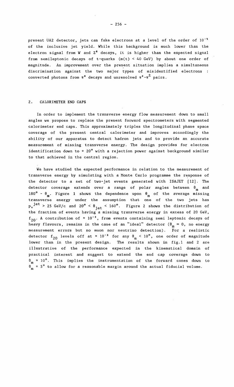
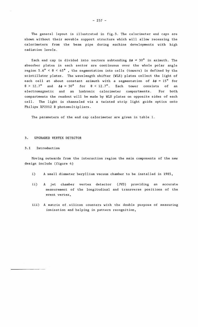
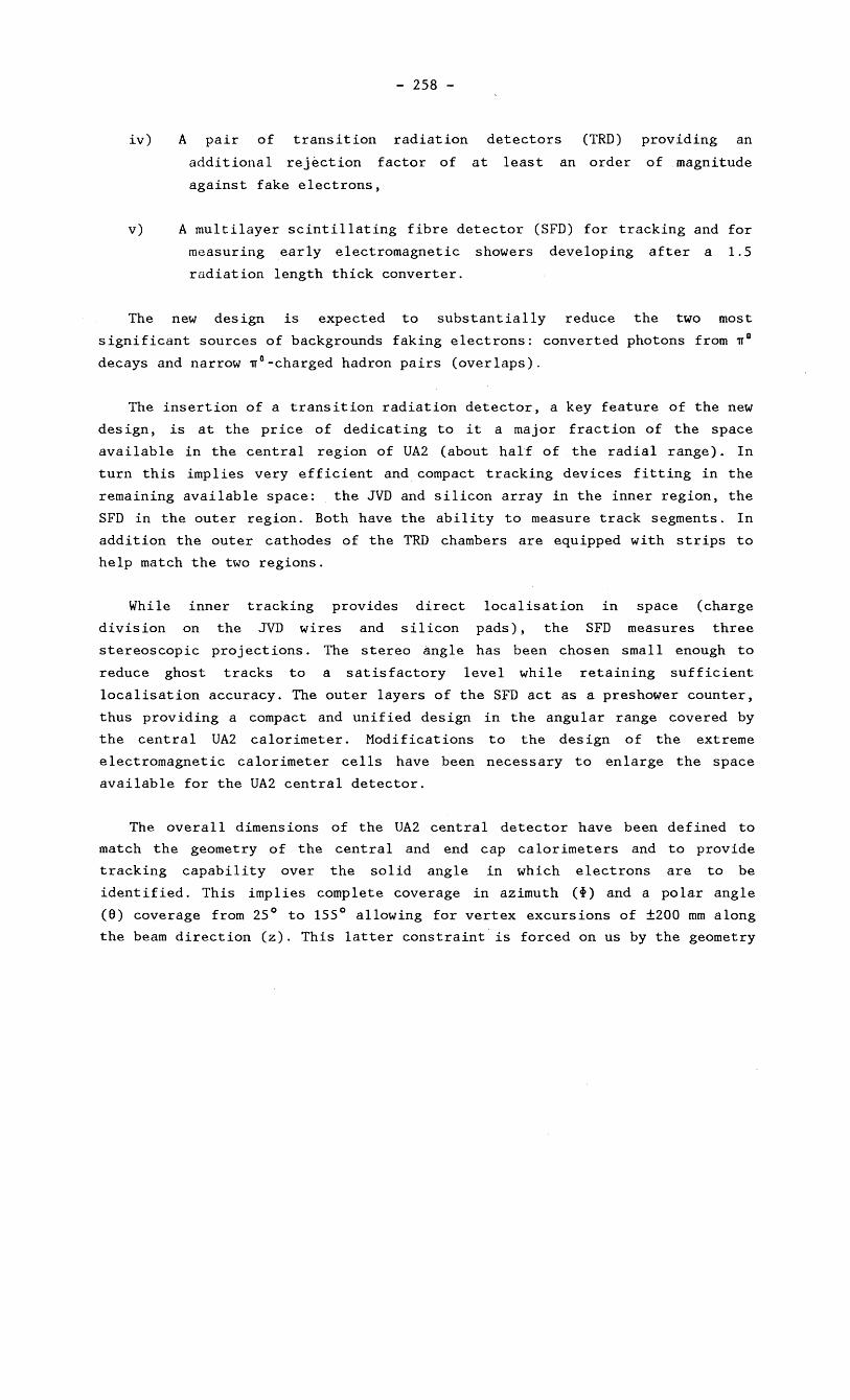
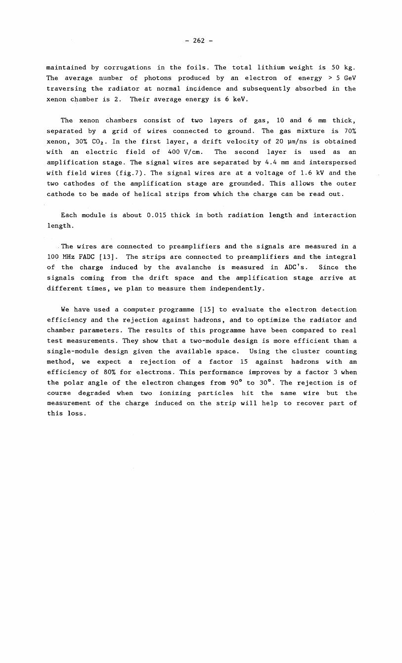
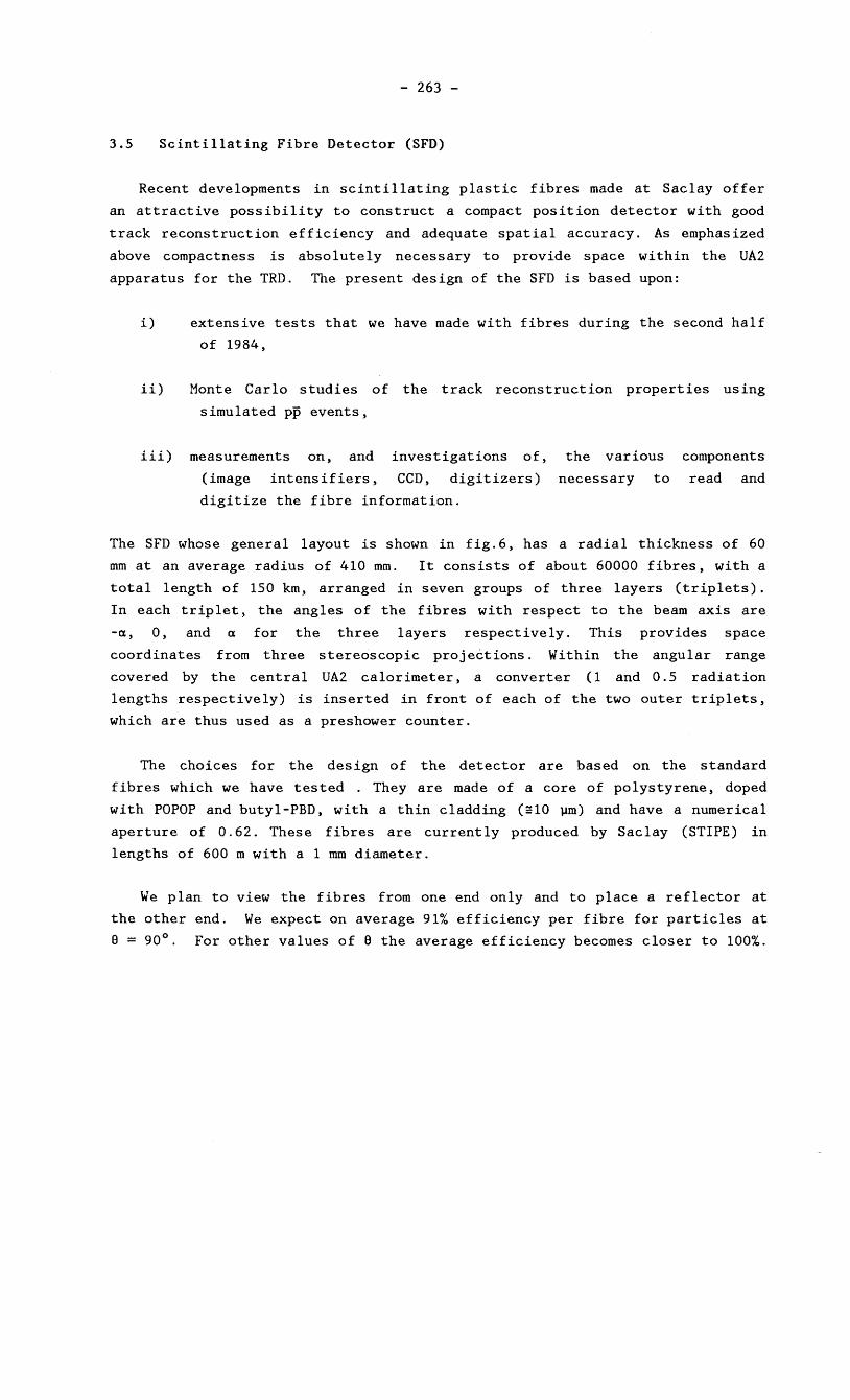
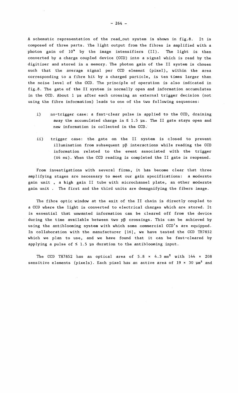
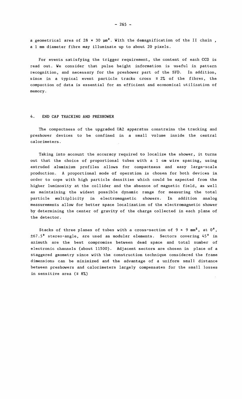
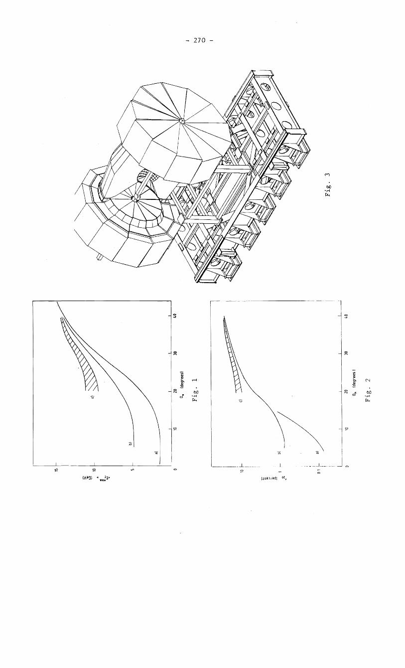
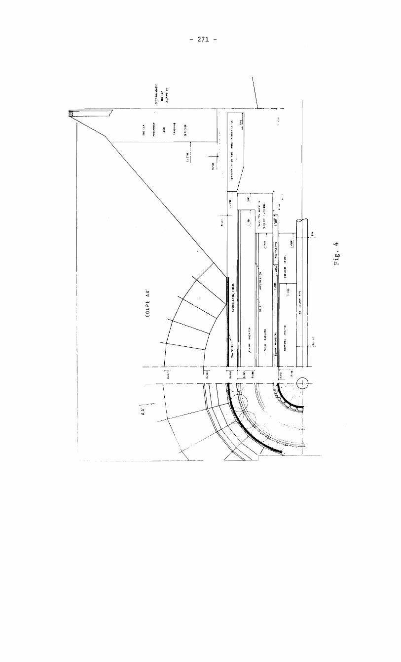
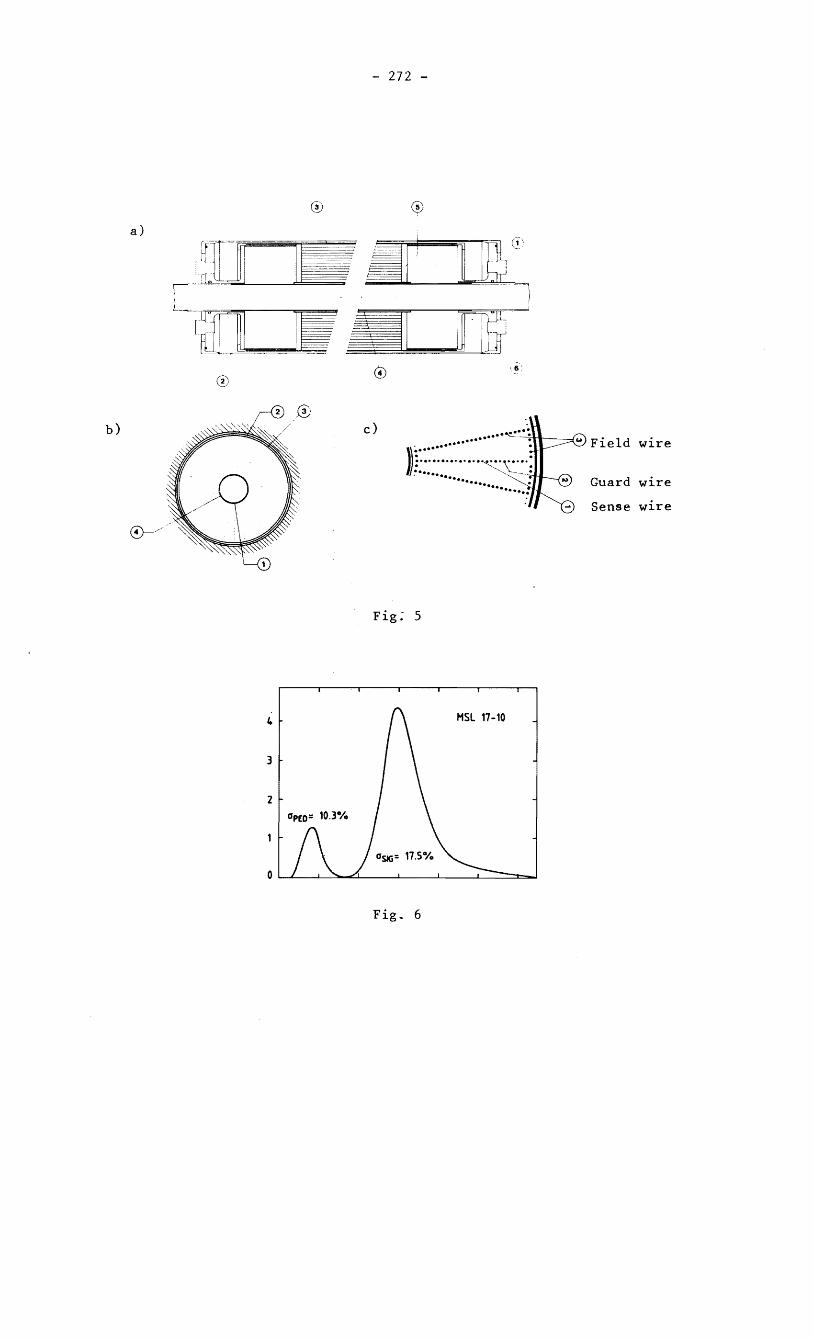
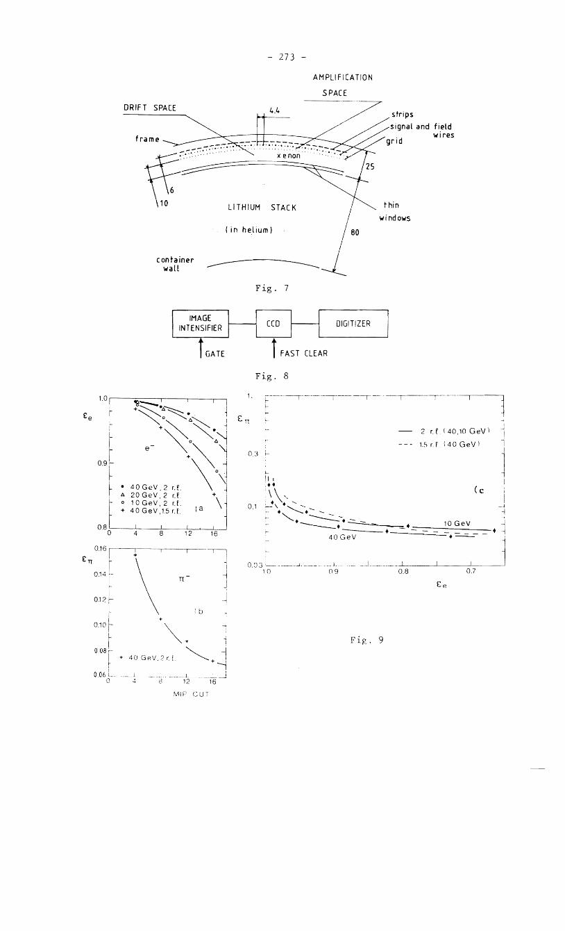