Embed Size (px)
Citation preview


NEW CATALOGUE ON ARBOR AND ADAPTER SYSTEMS
Pokolm Frästechnik GmbH & Co. KG
Adam-Opel-Straße 5 33428 Harsewinkel Germany
fon: +49 5247 9361-0 fax: +49 5247 9361-99
e-mail: [email protected]: www.pokolm.com
Imprint
© 2012 Pokolm Frästechnik GmbH & Co. KG
All rights reserved. Reproduction, modification, and any type of duplication in whole or in part is prohibited without written consent. This docu-
mentation replaces all previous issues. Dimensions and designs contained in previous documentation in digital or printed form may have chan-
ged as a result of modified standards. We reserve the explicit right to make changes based on new standards or technical advancements.
The graphical depiction of of products is for clarification purposes and does not always correspond in every case with every detail to the actual design.
Items conforming to older standards are delivered until their stocks are exhausted. NO liability is accepted for defects.
WWW.POKOLM.COM
The New Catalogue on Arbor and Adapter Systems from Pokolm
and adapter systems.
New and extremely customer-friendly: this catalogue is entirely structured around a tool-side connection!
Our arbor and adapter system product catalogue has been enhanced in order to meet the current industry requirements and also now includes important and interesting information.
catalogue structure. If you have any questions, suggestions or particular product requirements then do not hesitate to contact us! We are happy to be of service and look forward to hearing from you! Your Pokolm Team
INFORMATION AND CATALOGUE STRUCTURE
2

Being better means not just staying ahead of the competition but also scrutinising ones own products and ser-
vices looking for ways to improve and become more efficient. Pokolm is well-known for this practice. This is also
one of the reasons why successful practitioners choose Pokolm premium tools. This added value that gives Pokolm
customers a decisive edge over the competition is created by merging excellent products with outstanding technical
service advice and tailoring both entirely to the needs of the customer. The structure of the product range and the
corresponding documentation must also be 100% customer-oriented in accordance with Pokolm's standards.
The structure of the Pokolm arbor and adapter cata-
logue is customer-oriented. This is because it struc-
tured around a machine-side connection. Simply choose
the connection form and connection dimension in the
structure for the type of machine in use and all of the
corresponding tool connections will be listed thereun-
der. The arbors within this group are then categorised
according to the connection type and size.
THE STRUCTURE: 1. MACHINE , 2. TOOL
Screw-on arbors
Machine connection, e.g.
Shrinking arbors
Shell-type arbors
SK, HSK or BT in all common tappet forms
Tool connection, e.g.
Morse- taper shank Shrinking
SB
Collet chuck Drill
chuck
3

Pokolm Frästechnik GmbH & Co. KG
+49 5247 9361-0
+49 5247 9361-99
We want to make things simple for you: Take advantage of our other services!
u Order before 5:00 pm and your goods
will be sent the same day!
PURCHASE- AND INFO-HOTLINE
7:30 - 18:00 hrs (weekdays)
Electronic quotation with a „Click“
u This means that all information is just one "mouse click" away!
u By E-mail as a PDF-file
CD-ROM catalogue
u Comprehensive search functions u CAD/CAM data export u Shopping basket for enquiries and orders
u With links to detailed technical information
ORDER AND INFO-HOTLINE
4

Arbo
r and
Ada
pter
Sys
tem
s
Information and Know-How from page 2
Adapters, extensions and collet chucks from page 19
Hollow taper shanks HSK from page 33
Steep taper shanks SK / BT from page 65
Flange contact surfaces from page 111
Spindle systems / Shrink technology from page 116
Order / Request forms from page 119
Assembly instructions from page 128
Index from page 134
TABLE OF CONTENTS
Accessories from page 122
5

100,0
10,0
1,0
0,1
5.000 10.000 15.000 20.000 25.000 30.000 40.000 50.000
G 0,4
G 1
G 2,5
G 6,3
G 16
G 40
HSK 100 SK 50
HSK 80
HSK 50/HSK 63 F/SK 30/HSK 40/HSK 32
SK 40 HSK63
DIN/ISO 1940
SK/BT HSK
30 40 50 32 40 50 63 63 80 100
2,5 6,3 16 2,5 2,5 2,5 6,3 2,5 6,3 16
30.000 18.000 8.000 30.000 30.000 30.000 20.000 30.000 12.000 8.000
Deviations from this chart are possible – please tell us what your requirements are.
allo
wab
le li
mits
of b
alan
ce-e
rror
s in
[gm
m/k
g] o
rec
cent
ricity
e in
[m
]
Kind of taper
view
size
form
all all allall form Fall, except form F all
rpm
grade level
BALANCINGBalance grades of Pokolm arbors and adapters
Rpm
6
BALANCING - BALANCE QUALITY OF POKOLM ARBORS

e=U–m =
2· ·n–––––
60G=e· =
U· ·n–––––m·30
mr=e·m
––––r
Calculations and definitions
G 0,4G 1G 2,5G 6,3G 16G 40
e.g. microfinishing machinese.g. low-power motors, driving gears for grinding machinese.g. cutting tools, small arbors and adapters, electrical motors, turbinese.g. cutting tools, arbors and adapters, machine tool partse.g. big arbors, cardan shafts, drive shaftse.g. universal shafts, automotive wheels, crank gear drives
Balancing grade classifications and typical applications:
Formulas:
Calculation of remaining balance
error in [gmm/kg]
Calculation of radian frequency
in [1/s]
Calculation of balancing grade levels
in [mm/s]
Calculation of compensation mass
Definitions and dimensions:
= balancing grade level in [mm/s] = balance error [m · e] in [gmm]
= remaining balance error in [gmm/kg] or eccentricity of center in [ m]
= rotor weight in [g]
= frequency (n/60) in [1/s]= remaining balance error in [mm]
= rpm= remaining balance error
) in [N]
G U
e m
fr
nmr
F
7

Balance errors and balancing
Definition of balance error
Rotational axis mass axis Rotational axis = mass axisA balance error occurs when the rotational axis of a rotor part does not correspond to its mass axis.
Reasons for Balance Errors:
u Indexing seat for tool changer in SK and HSK u Driving slots in SK and BT u Driving slots in HSK- A, C, CE u any kinds of flats on tool shanks u Locking srews for tool shanks with flats u Non-uniform pitch on cutting tools u Collets and tightening nuts u Production tolerances
Balance errors can be eliminated either by adding mate-rial or by drilling corrective holes to remove material. See illustrations of corrective drill holes below:
Unbalanced arbor Balanced arbor with cor-rective drill hole
Balancing by drilling corrective holes. Sample
calculations and detailed illus-tration, see next page.
BALANCE ERRORS AND BALANCING
8

<==> G = U =U · 2 · · n
m · 60
G · m · 60
2 · · n
==> U = U =6,3 · 760 · 60
2 · · 20.0002,286 gmm
==> e = e =2,286
7603 μm
==> ==> mr = mr = mr =m · e
r
760 · 0,003
31,50,072g
Shrinking Arbor HSK 63A: 50 08 A63 Sweight: 760 gramsTaper radius: 31,5 mmBalance grade: G 6.3 at 20,000 rpm
By means of precision balancing, the remaining balancing error has been minimized to 0.072 g (in relation to the taper radius of the arbor of 31.5 mm).
Balancing, particularly in connection with high concentricity, prevents your spindle from damage, because it decre-ases the centrifugal forces and reduces the formation of vibrations. This results in an extremely smooth operation, which greatly increases machining and component quality. In addition, it allows higher cutting parameters – both in high-speed milling and in conventional milling.
Note to illustration: ”S” = mass axis
Example of a calculation:
Calculation of remaining balance error in example above:
Your advantages – why this is such an important subject.
9

Shrinking arbors
SK-zero reach
Plain shank shrinking
extensions
Short taper shrinking
extensions
Dense-antivibration & solid carbide
adapters for thread connections
Extensions andreductions for
thread connections
Morse taper shankadapters for thread
connections
Morse taper shank shrinking
extensions
DuoPlug®- Solid carbide
adapters
DuoPlug®- Shrinking adapters
Cutter bodiesfor round inserts
Slotworx®-Cutter bodies
Ball nose cutter bodies
Trigaworx®-Cutter bodies
Cutter bodies for rhombic inserts
Quadworx®
Cutter bodiesCorner radius and
toric end millsEnd millsBall nose
cutter bodies
Milling cutter bodies with DuoPlug®-connections Solid carbide end mills
THE POKOLM TOOL SYSTEMover 500000 combination possibilities
Pokolm short taperarbors
Morse taper adapters(Reduction sleeves SK
and HSK to MTS)SK SK SKHSK HSK HSKBT
THE POKOLM TOOL SYSTEM
10

Arbors for thread connections ER-Collet chucksarbors
Arbors for shell-type milling cutter bodies
Direct spindle mounting
Extensions and re- ductions for thread
connections
End mill bodies with thread connections Shell-type milling cutter bodies
Plain shank end mills*
*Using suitable shrinking units, you can combine all plain shank end mills, adapters and extensions with shrinking adapters and arbors.
Quadworx®Quadworx® Slotworx®Slotworx®
Shrinking combinationsShort taper combinationsMorse taper combinations
Thread combinationsShell-type combinationsER-Collet combinationsDuoPlug®-combinations
SK SK SKHSK BT BT BTHSK HSK
Shell-type-/Extensionadapters
ER-Shrinking extensions
cylindrical adap-ters for thread connections*
Shell-type extensions
for round inserts
11

TECHNOLOGICAL COMPARISONThread Connection vs. Pokolm DuoPlug® Connection
Where the difference is:
Pokolm Thread Connection –
our high-performance standard
Our patented protected DuoPlug® System –
the perfect increased performance
Pokolm Thread Connection Pokolm DuoPlug®=Shrink and Screw
The black arrows show the retention and supporting forces. end face
fit zonethread
This standard thread connection is produced with the best tolerances possible using the latest technology. We maximize the efficiency of our Pokolm thread connections by optimizing our design of arbors, adapters, and milling cutter bodies.
The black arrows show the retention and supporting forces.
flange contact surface
shrink fitfine thread
Our Pokolm DuoPlug® system offers optimum rigidity and extremely high precision and concentricity. As a supple-ment to conventional thread connections, the retention and supporting forces between cutting tool and adapter act along the entire surface of the shrink fit and a large part of the shrink thread.For more information, please see the assembling and dismantling instructions for our Duo-Plug® system in the ”Operation Data” chapter.
DuoPlug® perfects the thread connection by means of greatly increased retention forces, resulting in the highest possible precision for extremely slim dimensions.
The fact is:
12
TECHNOLOGICAL COMPARISON
Pokolm Thread Connection –
our high-performance standard
Our patent protected DuoPlug® System –
the perfect increase
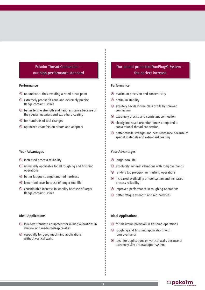
Performance
u no undercut, thus avoiding a rated break-point
u extremely precise fit zone and extremely precise flange contact surface
u better tensile strength and heat resistance because of the special materials and extra-hard coating
u for hundreds of tool changes
u optimized chamfers on arbors and adapters
Your Advantages
u increased process reliability
u universally applicable for all roughing and finishing operations
u better fatigue strength and red hardness
u lower tool costs because of longer tool life
u considerable increase in stability because of larger flange contact surface
Ideal Applications
u low-cost standard equipment for milling operations in shallow and medium-deep cavities
u especially for deep machining applications without vertical walls
Performance
u maximum precision and concentricity
u optimum stability
u absutely backlash-free class of fits by screwed connection
u extremely precise and consistant connection
u clearly increased retention forces compared to conventional thread connection
u better tensile strength and heat resistance because of special materials and extra-hard coating
Your Advantages
u longer tool life
u absolutely minimal vibrations with long overhangs
u renders top precision in finishing operations
u increased availability of tool system and increased process reliability
u improved performance in roughing operations
u better fatigue strength and red hardness
Ideal Applications
u for maximum precision in finishing operations
u roughing and finishing applications with long overhangs
u ideal for applications on vertical walls because of extremely slim arbor/adapter system
13

SK 30BT 30SK 50BT 50 SK 40BT 40
AND THERE'S STILL MORE E.G. SK/BT30 AND HSK25
As a Pokolm customer you are accustomed to a broad
range of products and a full service with regards tech-
nical matters. "Everything from a single source," is our
motto to ensure ease of purchase and optimum use of our
products. By this we do not just mean standard products.
Special items not offered by everyone enhance the ran-
ge of products for our customers - even in the area of
tool arbors. This is why you will also find designs with
SK30 and BT30 machine-side connections in the Pokolm
catalogue of arbor and adapter systems.
AND WE CAN STILL OFFER MORE
14
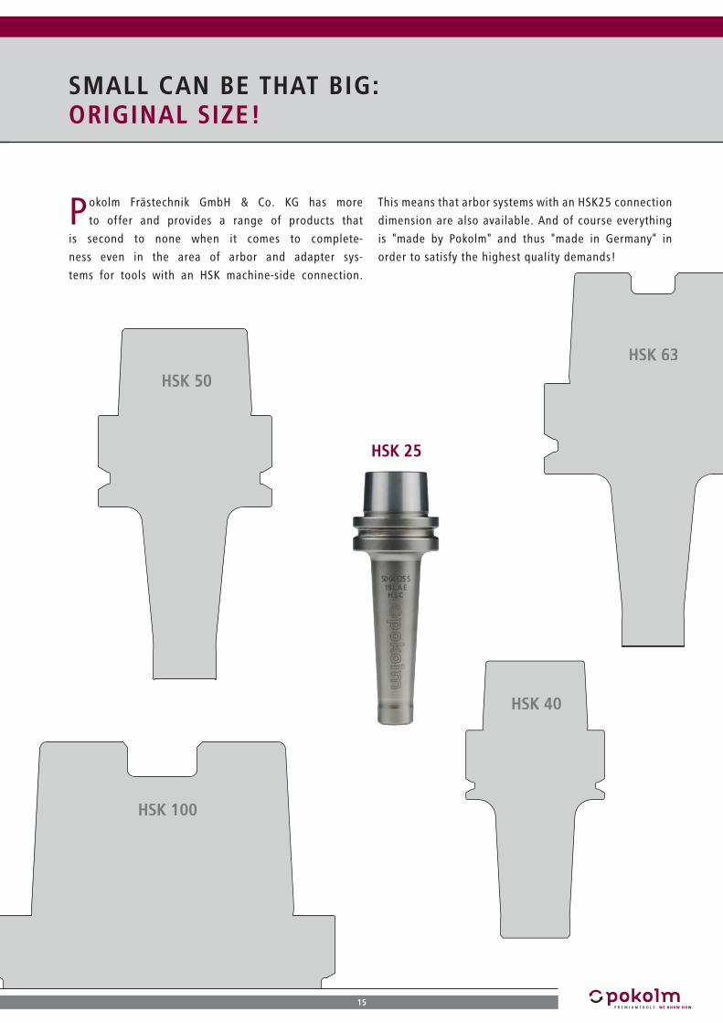
HSK 25
HSK 100
HSK 63
HSK 50
SMALL CAN BE THAT BIG: ORIGINAL SIZE!
Pokolm Frästechnik GmbH & Co. KG has more
to offer and provides a range of products that
is second to none when it comes to complete-
ness even in the area of arbor and adapter sys-
tems for tools with an HSK machine-side connection.
This means that arbor systems with an HSK25 connection
dimension are also available. And of course everything
is "made by Pokolm" and thus "made in Germany" in
order to satisfy the highest quality demands!
15
HSK 40

1
2
3
4
5
6
THE POKOLM ARBOR SYSTEM
The optimum solution for your application
ARBO
RS (T
APER
ED) f
or T
HREA
-
DED
SHA
NK
END
MIL
LS
ARBO
RS fo
r THR
EAD
-CO
N-
NEC
TIO
NS
CYLI
ND
RICA
L
RED
UCTI
ON
SLE
EVES
with
MO
RSE
TAPE
R AD
APTE
RS
ARBO
RS fo
r SHE
LL T
YPE
MIL
LIN
G C
UTTE
R BO
DIE
S
ARBO
RS w
ith D
IREC
T
SPIN
DLE
MO
UNTI
NG
SHRI
NKI
NG
ARB
ORS
STAN
DARD
STY
LE
u rigid, low-cost standard design
u large variety of types and lengths provides additional flexibility by using extensions and reductions
u gaining rigidity by avoiding unnecessary interfaces
u milling in shallow to deep profiles, for small milling cutter bodies up to 42 mm diam.
u slim shape
u additional rigidity by avoiding unnecessary interfaces
u where needed: additional flexibility with extensions and reductions
u medium machining depths, especially on deep vertical walls for small milling cutter bodies up to 42 mm diam.
u Morse taper adapters for threaded shank end mill bodies and for shrinking processes available for solid carbide tools
u fast and flexible tool change
u modular design allows machining of deep slots and cavities
u for standard milling operations with normal rigidity and accuracy requirements, for milling cutter bodies up to 42 mm diam.
u slim style with 3° draft angle in direction of collar
u direct shrink-grip of solid carbide tooling
u additional rigidity by avoiding unnecessary interfaces
u improved concentricity
u combinable with solid carbide and dense antivibration adapters (see page 22-24)
u machining situations in narrow space con-ditions for solid carbide end mills up to 25 mm diam., and when combined with solid carbide or dense antivibration adapters even for milling cutter bodies with up to 42 mm diam.
u rigid variant, in particular for roughing or pre-finishing operations with large cutter diameters and a large variety of designs
u additional rigidity by avoiding unnecessary interfaces
u shallow to deep machining situations for pre-finishing and rough machining, for milling cutter diameters from 42 mm to 125 mm and larger
u extremely rigid style through direct spindle mounting
u excellent machining conditions in deep slots or cavities
u additional rigidity by avoiding interfaces
u deep and extremely deep machining situations on SK 50 machines which require extreme rigidity, for milling cutter diame-ters from 52 to 125 mm
Arbor System Advantages Recommended applications
16
THE POKOLM ARBOR SYSTEM

7
8
9
10
11
12
SHRI
NKI
NG
ARB
ORS
, RE
INFO
RCED
DES
IGN
ARBO
R CO
MBI
NAT
ION
S w
ith
DUO
PLUG
® A
DAPT
ERS
ARBO
R CO
MBI
NAT
ION
S w
ith D
ENSE
AN
TI-
VIBR
ATIO
NAD
APTE
RS
ZERO
-REA
CH A
RBO
RSER
20 P
RECI
SIO
N
COLL
ET C
HUCK
SSH
ORT
TAP
ER S
YSTE
M
u 4.5° draft angle, reinforced shank
u direct shrink grip of solid carbide end mills
u additional rigidity by avoiding unnecessary interfaces
u improved concentricity
u milling with increased requirements for arbor rigidity for solid carbide end mills up to 20 mm diam.
u extremely long and slim arbor combina-tions
u greatest possible avoidance of vibrations by using solid carbide adapters
u DuoPlug® connection for maximum precisi-on and concentricity
u stronger retention forces
u machining in deep cavities also with verti-cal walls
u roughing operations with maximum reten-tion forces
u finishing operations with very high require-ments for surface finish
u up to cutter diam. of 25 mm
u long and slim arbor combinations
u minimal vibrations because of special den-se antivibration material
u thread connection, no shrinking process necessary
u machining in deep cavities also with verti-cal walls
u for narrow and deep moulds and dies
u machining applications with normal vibrati-on tendency
u for cutter diam. of up to 42 mm
u extra slim arbor combination
u extremely small dimensions
u especially for machining components in reduced space situations, narrow and deep slots, etc.
u for solid carbide end mills with 4 and 6 mm shank diam.
u by directly shrinking the solid carbide end mill or dense antivibration adaptor in the arbor taper, you can machine vertical walls right up to the arbor collar. This means great increase in rigidity because of the reduced distance between the spindle and tool.
u machining of extremely deep cavities with vertical walls in very limited space and with limited movement of Z-axis, and high requirements for rigidity and vibration-free milling
u universal and good value solution, direct grip of solid carbide end mills via collet without a shrinking device
u also grips unusual shank diameters and shank diameters smaller than 3 mm
u for fast changing applications
u for finishing, pre-finishing, and moderate roughing operations
Arbor System Advantages Recommended Applications
Please note: Zero-reach arbors cannot be ordered separately. We only supply them in a shrink-grip connection with a solid carbide or dense antivibration adapter. (Please indicate desired adapter on purchase order form.)
17

18
18

Page
Pokolm DuoPlug® M 7 - M 16 20
Solid carbide adapters - for screw-on end mills
M 8 - M 16 22
Dense antivibration adapters - for screw-on end mills
M 5 - M 16 23
MTK adapters - for screw-on end mills M 8 - M 16 25
Pokolm extensions - for screw-on end mills M 8 - M 16 27
Pokolm reductions - for screw-on end mills M 5 - M 12 28
Pokolm cyl. shaf t - DIN 1835 A M 5 - M 16 29
Pokolm cyl. shaf t - DIN 1835 B M 5 - M 16 30
Precision collet chucks 31
32
ADAPTERS, EXTENSIONS, AND COLLET CHUCKSADAPTERS, EXTENSIONS, AND COLLET CHUCKS
19

20
latest items! available as long as stock lasts on request stock item, subject to confirmation
POKOLM DUOPLUG®M 7 - M 16
M 7 - M 16
Catalogue n
o.
Form
/DIN
ref. a
ccesso
ries
features
d1 l3 A d3 d4 d2 l2 l1
d4
d3
d1
l 3
l 2
d2M 7
20 07 603 M 7 20 - 10.8 11.9 diam. 12
- 68 -
40 07 603 M 7 40 - 10.8 11.9 diam. 12
- 88 -
60 07 603 M 7 60 - 10.8 15.9 diam. 16
- 108 -
80 07 603 M 7 80 - 10.8 15.9 diam. 16
- 128 -
M 10
25 10 603 M 10 25 - 15 15.9 diam. 16
- 73 -
50 10 603 M 10 50 - 15 15.9 diam. 16
- 98 -
75 10 603 M 10 75 - 15 15.9 diam. 16
- 123 -
100 10 603 M 10 100 - 15 15.9 diam. 16
- 148 -
125 10 603 M 10 125 - 15 15.9 diam. 16
- 173 -
150 10 603 M 10 150 - 15 15.9 diam. 16
- 200 -
M 12
25 12 603 M 12 25 - 18.5 19.9 diam. 20
- 75 -
50 12 603 M 12 50 - 18.5 19.9 diam. 20
- 100 -
75 12 603 M 12 75 - 18.5 19.9 diam. 20
- 125 -
100 12 603 M 12 100 - 18.5 19.9 diam. 20
- 150 -
125 12 603 M 12 125 - 18.5 19.9 diam. 20
- 175 -
150 12 603 M 12 150 - 18.5 19.9 diam. 20
- 200 -
175 12 603 M 12 175 - 18.5 19.9 diam. 20
- 225 -
The solid carbide adapters which are part of the POKOLM DuoPlug®-System are especially well suited for HSC and provide absolutely backlash-free fitting and extreme precision combined with the retention force required for roughening applications.
1 / 2
ADAPTERS, EXTENSIONS, AND COLLET CHUCKS

21
M 7 - M 16
Catalogue n
o.
Form
/DIN
ref. a
ccesso
ries
features
d1 l3 A d3 d4 d2 l2 l1
d4
d3
d1
l 3
l 2
d2M 16
25 16 603 M 16 25 - 23.4 24.9 diam. 25
- 81 -
50 16 603 M 16 50 - 23.4 24.9 diam. 25
- 106 -
75 16 603 M 16 75 - 23.4 24.9 diam. 25
- 131 -
100 16 603 M 16 100 - 23.4 24.4 diam. 25
- 156 -
125 16 603 M 16 125 - 23.4 24.9 diam. 25
- 181 -
150 16 603 M 16 150 - 23.4 24.9 diam. 25
- 206 -
175 16 603 M 16 175 - 23.4 24.9 diam. 25
- 231 -
200 16 603 M 16 200 - 23.4 24.9 diam. 25
- 256 -
2 / 2

22
latest items! available as long as stock lasts on request stock item, subject to confirmation
SOLID CARBIDE ADAPTERS - FOR SCREW-ON END MILLSM 8 - M 16
M 8 - M 16
Catalogue n
o.
Form
/DIN
ref. a
ccesso
ries
features
d1 l3 A d3 d4 d2 l2 l1
d2
l 2l 3
l 1
d4d3
d1
M 8
40 08 606 M 8 40 - 14.2 15.3 diam. 16
- 88 9
60 08 606 M 8 60 - 14.2 15.3 diam. 16
- 108 9
80 08 606 M 8 80 - 14.2 15.3 diam. 16
- 128 9
100 08 606 M 8 100 - 14.2 15.3 diam. 16
- 148 9
120 08 606 M 8 120 - 14.2 15.3 diam. 16
- 168 9
M 10
60 10 606 M 10 60 - 18.5 19.3 diam. 20
- 110 9
80 10 606 M 10 80 - 18.5 19.3 diam. 20
- 130 9
100 10 606 M 10 100 - 18.5 19.3 diam. 20
- 150 9
120 10 606 M 10 120 - 18.5 19.3 diam. 20
- 170 9
140 10 606 M 10 140 - 18.5 19.3 diam. 20
- 190 9
M 12
80 12 606 M 12 80 - 23 24.3 diam. 25
- 136 9
100 12 606 M 12 100 - 23 24.3 diam. 25
- 156 9
120 12 606 M 12 120 - 23 24.3 diam. 25
- 176 9
140 12 606 M 12 140 - 23 24.3 diam. 25
- 196 9
160 12 606 M 12 160 - 23 24.3 diam. 25
- 216 9
M 16
100 16 606 M 16 100 - 31.5 34.3 diam. 36
- 160 9
150 16 606 M 16 150 - 31.5 34.3 diam. 36
- 210 9
200 16 606 M 16 200 - 31.5 34.3 diam. 36
- 260 9
250 16 606 M 16 250 - 31.5 34.3 diam. 36
- 310 9
300 16 606 M 16 300 - 31.5 34.3 diam. 36
- 360 9
POKOLM solid carbide adapters for screw-on end mills are well suited for HSC and with extreme precision provide the retention force required for roughening applica-tions. All adapters have an internal coolant supply as standard.
ADAPTERS, EXTENSIONS, AND COLLET CHUCKS NEW

23
DENSE ANTIVIBRATION ADAPTERS - FOR SCREW-ON END MILLSM 5 - M 16
POKOLM solid carbide adapters for screw-on end mills are characterised by their out-standing precision. These adapters are excellent for HSC finishing processes thanks to their vibration-reducing characteristics. Adapters are also available with an internal coolant supply upon request
M 5 - M 16
Catalogue n
o.
Form
/DIN
ref. a
ccesso
ries
features
d1 l3 A d3 d4 d2 l2 l1
d2
l 2l 3
l 1
d4d3
d1
M 5
40 05 601 M 5 40 - 9.5 11.3 diam. 12
- 85 9
60 05 601 M 5 60 - 9.5 11.3 diam. 12
- 105 9
80 05 601 M 5 80 - 9.5 11.3 diam. 12
- 125 9
M 8
40 08 601 M 8 40 - 14.2 15.3 diam. 16
- 88 9
60 08 601 M 8 60 - 14.2 15.3 diam. 16
- 108 9
80 08 601 M 8 80 - 14.2 15.3 diam. 16
- 128 9
100 08 601 M 8 100 - 14.2 15.3 diam. 16
- 148 9
120 08 601 M 8 120 - 14.2 15.3 diam. 16
- 168 9
150 08 601 M 8 150 - 14.2 15.3 diam. 16
- 198 9
M 10
60 10 601 M 10 60 - 18.5 19.3 diam. 20
- 110 9
80 10 601 M 10 80 - 18.5 19.3 diam. 20
- 130 9
100 10 601 M 10 100 - 18.5 19.3 diam. 20
- 150 9
120 10 601 M 10 120 - 18.5 19.3 diam. 20
- 170 9
140 10 601 M 10 140 - 18.5 19.3 diam. 20
- 190 9
M 12
75 12 601 M 12 75 - 23 24.3 diam. 25
- 131 9
100 12 601 M 12 100 - 23 24.3 diam. 25
- 156 9
125 12 601 M 12 125 - 23 24.3 diam. 25
- 181 9
150 12 601 M 12 150 - 23 24.3 diam. 25
- 206 9
175 12 601 M 12 175 - 23 24.3 diam. 25
- 231 9
1 / 2

24
latest items! available as long as stock lasts on request stock item, subject to confirmation
M 5 - M 16
Catalogue n
o.
Form
/DIN
ref. a
ccesso
ries
features
d1 l3 A d3 d4 d2 l2 l1
d2
l 2l 3
l 1
d4d3
d1
M 16
100 16 601 M 16 100 - 31.5 34.3 diam. 36
- 160 9
150 16 601 M 16 150 - 31.5 34.3 diam. 36
- 210 9
200 16 601 M 16 200 - 31.5 34.3 diam. 36
- 260 9
250 16 601 M 16 250 - 31.5 34.3 diam. 36
- 310 9
300 16 601 M 16 300 - 31.5 34.3 diam. 36
- 360 9
POKOLM solid carbide adapters for screw-on end mills are characterised by their out-standing precision. These adapters are excellent for HSC finishing processes thanks to their vibration-reducing characteristics. Adapters are also available with an internal coolant supply upon request
DENSE ANTIVIBRATION ADAPTERS - FOR SCREW-ON END MILLSM 5 - M 16
2 / 2
ADAPTERS, EXTENSIONS, AND COLLET CHUCKS

25
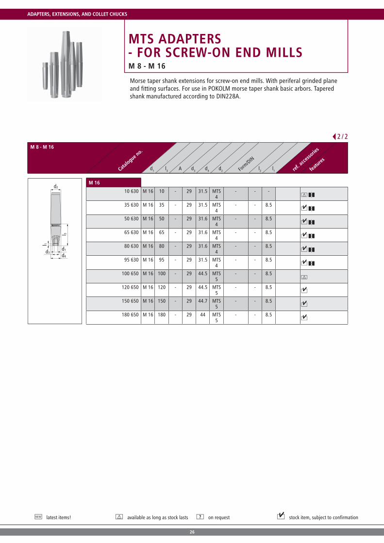
MTS ADAPTERS - FOR SCREW-ON END MILLSM 8 - M 16
Morse taper shank extensions for screw-on end mills. With periferal grinded plane and fitting surfaces. For use in POKOLM morse taper shank basic arbors. Tapered shank manufactured according to DIN228A.
M 8 - M 16
Catalogue n
o.
Form
/DIN
ref. a
ccesso
ries
features
d1 l3 A d3 d4 d2 l2 l1
d2
d4
l 3
l 1
d3d1
M 8
20 670 M 8 20 - 13.8 18 MTS 2
- - -
40 670 M 8 40 - 13.8 18 MTS 2
- - 8.5
60 670 M 8 60 - 13.8 18 MTS 2
- - 8.5
80 670 M 8 80 - 13.8 24 MTS 3
- - 8.5
100 670 M 8 100 - 13.8 24.1 MTS 3
- - 8.5
M 10
20 680 M 10 20 - 18 18 MTS 2
- - -
40 680 M 10 40 - 18 18 MTS 2
- - -
60 680 M 10 60 - 18 18 MTS 2
- - -
80 680 M 10 80 - 18 24 MTS 3
- - 8.5
100 680 M 10 100 - 18 23.6 MTS 3
- - 8.5
M 12
10 610 M 12 10 - 21 24 MTS 3
- - -
30 610 M 12 30 - 21 23.6 MTS 3
- - 8.5
45 610 M 12 45 - 21 24.1 MTS 3
- - 8.5
60 610 M 12 60 - 21 24.1 MTS 3
- - 8.5
75 610 M 12 75 - 21 24.1 MTS 3
- - 8.5
95 610 M 12 95 - 21 24.1 MTS 3
- - 8.5
120 610 M 12 120 - 21 31.6 MTS 4
- - 8.5
1 / 2
26
latest items! available as long as stock lasts on request stock item, subject to confirmation
M 8 - M 16
Catalogue n
o.
Form
/DIN
ref. a
ccesso
ries
features
d1 l3 A d3 d4 d2 l2 l1
d2
d4
l 3
l 1
d3d1
M 16
10 630 M 16 10 - 29 31.5 MTS 4
- - -
35 630 M 16 35 - 29 31.5 MTS 4
- - 8.5
50 630 M 16 50 - 29 31.6 MTS 4
- - 8.5
65 630 M 16 65 - 29 31.6 MTS 4
- - 8.5
80 630 M 16 80 - 29 31.6 MTS 4
- - 8.5
95 630 M 16 95 - 29 31.5 MTS 4
- - 8.5
100 650 M 16 100 - 29 44.5 MTS 5
- - 8.5
120 650 M 16 120 - 29 44.5 MTS 5
- - 8.5
150 650 M 16 150 - 29 44.7 MTS 5
- - 8.5
180 650 M 16 180 - 29 44 MTS 5
- - 8.5
Morse taper shank extensions for screw-on end mills. With periferal grinded plane and fitting surfaces. For use in POKOLM morse taper shank basic arbors. Tapered shank manufactured according to DIN228A.
MTS ADAPTERS - FOR SCREW-ON END MILLSM 8 - M 16
2 / 2
ADAPTERS, EXTENSIONS, AND COLLET CHUCKS

27
POKOLM EXTENSIONS - FOR SCREW-ON END MILLSM 8 - M 16
Cylindrical threaded extensions for reaching deep cavities rapidly and effectively. Manufactured according to the POKOLM standard with smoothed plane and mating surfaces as well as an internal coolant supply.
M 8 - M 16
Catalogue n
o.
Form
/DIN
ref. a
ccesso
ries
features
d1 l3 A d3 d4 d2 l2 l1
d3
l 3
d2
d4
d1
M 8
08 40 780 M 8 40 - 13.8 13.8 M 8 - - -
08 60 780 M 8 60 - 13.8 13.8 M 8 - - -
M 10
10 40 780 M 10 40 - 18 18 M 10 - - -
10 60 780 M 10 60 - 18 18 M 10 - - -
M 12
12 40 780 M 12 40 - 21 21 M 12 - - -
12 60 780 M 12 60 - 21 21 M 12 - - -
M 16
16 40 780 M 16 40 - 29 29 M 16 - - -
16 60 780 M 16 60 - 29 29 M 16 - - -

28
latest items! available as long as stock lasts on request stock item, subject to confirmation
POKOLM REDUCTIONS - FOR SCREW-ON END MILLSM 5 - M 12
M 5 - M 12
Catalogue n
o.
Form
/DIN
ref. a
ccesso
ries
features
d1 l3 A d3 d4 d2 l2 l1
d4
d2
l 3
l 1
d3
d1
M 5
08 40 781 M 5 40 - 9.5 13.8 M 8 - - 7.8
M 8
10 40 781 M 8 40 - 13.8 18 M 10 - - 6.5
12 60 781 M 8 60 - 13.8 21 M 12 - - 7.8
M 10
12 40 781 M 10 40 - 18 21 M 12 - - 7.8
16 60 781 M 10 60 - 18 29 M 16 - - 7.8
M 12
16 40 781 M 12 40 - 21 29 M 16 - - 7.8
Tapered threaded reductions for reaching deep cavities with low draft angles rapidly and effectively. Manufactured according to the POKOLM standard with smoothed plane and mating surfaces as well as an internal coolant supply.
ADAPTERS, EXTENSIONS, AND COLLET CHUCKS

29
POKOLM CYL. SHAFT - DIN 1835 AM 5 - M 16
Threaded adapters with a cylindrical shaft according to DIN 1835A. For use in collet chuck arbors or also hydraulic expansion chucks.Manufactured according to the POKOLM standard with smoothed plane and mating surfaces and an internal coolant supply option.
M 5 - M 16
Catalogue n
o.
Form
/DIN
ref. a
ccesso
ries
features
d1 l3 A d3 d4 d2 l2 l1
d2
l 2l 3
l 1
d4d3
d1
M 5
10 12 600 G M 5 10 - 9.5 11.8 diam. 12
- 55 7.8
20 12 600 G M 5 20 - 9.5 11.5 diam. 12
- 65 7.8
M 8
20 16 600 G M 8 20 - 13.8 15.8 diam. 16
- 68 7.8
40 16 600 G M 8 40 - 13.8 15.8 diam. 16
- 88 7.8
M 10
25 20 600 G M 10 25 - 18 19.8 diam. 20
- 75 7.8
45 20 600 G M 10 45 - 18 19.8 diam. 20
- 95 7.8
M 12
30 25 600 G M 12 30 - 21 24.9 diam. 25
- 86 7.8
50 25 600 G M 12 50 - 21 24.8 diam. 25
- 106 7.8
M 16
50 32 600 G M 16 50 - 29 31.8 diam. 32
- 110 7.8

30
latest items! available as long as stock lasts on request stock item, subject to confirmation
POKOLM CYL. SHAFT - DIN 1835 BM 5 - M 16
M 5 - M 16
Catalogue n
o.
Form
/DIN
ref. a
ccesso
ries
features
d1 l3 A d3 d4 d2 l2 l1
d2
l 2l 3
l 1
d4d3
d1
M 5
10 12 600 M 5 10 - 9.5 11.8 diam. 12
- 55 -
20 12 600 M 5 20 - 9.5 11.5 diam. 12
- 65 -
M 8
20 16 600 M 8 20 - 13.8 15.8 diam. 16
- 68 7.8
40 16 600 M 8 40 - 13.8 15.8 diam. 16
- 88 7.8
M 10
25 20 600 M 10 25 - 18 19.8 diam. 20
- 75 7.8
45 20 600 M 10 45 - 18 19.8 diam. 20
- 95 7.8
M 12
30 25 600 M 12 30 - 21 24.9 diam. 25
- 86 7.8
50 25 600 M 12 50 - 21 24.9 diam. 25
- 106 7.8
M 16
50 32 600 M 16 50 - 29 31.8 diam. 32
- 110 7.8
Threaded shank adapter with a cylindrical shaft and an additional Weldon collet surface according to DIN 1835B. For use in Weldon arbors.Manufactured according to the POKOLM standard with smoothed plane and mating surfaces and an internal coolant supply option.
ADAPTERS, EXTENSIONS, AND COLLET CHUCKS

31
PRECISION COLLET CHUCKS
Precision collet chucks according to DIN 6499-B Bi-conical - collet chucksslotted on both endsConcentricity 6 mRepeat accuracy 6 m
Collet chucks in other sizes and designs upon request.
Catalogue n
o.
Form
/DIN
ref. a
ccesso
ries
features
d1 l3 A d3 d4 d2 l2 l1
d2
d3-d1
ER 16
ER16 1-2 diam. 2
- - 1 - ER 16 - - - A, B
ER16 2-3 diam. 3
- - 2 - ER 16 - - - A, B
ER16 3-4 diam. 4
- - 3 - ER 16 - - - A, B
ER16 4-5 diam. 5
- - 4 - ER 16 - - - A, B
ER16 5-6 diam. 6
- - 5 - ER 16 - - - A, B
ER16 7-8 diam. 8
- - 7 - ER 16 - - - A, B
ER16 9-10 diam. 10
- - 9 - ER 16 - - - A, B
Accessories
16 501
A > Page 124
ER16 001
B > Page 125
NEW

32
latest items! available as long as stock lasts on request stock item, subject to confirmation
PRECISION COLLET CHUCKS
Catalogue n
o.
Form
/DIN
ref. a
ccesso
ries
features
d1 l3 A d3 d4 d2 l2 l1
d2
d3-d1
ER 20
ER20 0,5-1 diam. 1
- - 0.5 - ER 20 - - - A, B
ER20 1-2 diam. 2
- - 1 - ER 20 - - - A, B
ER20 2-3 diam. 3
- - 2 - ER 20 - - - A, B
ER20 3-4 diam. 4
- - 3 - ER 20 - - - A, B
ER20 4-5 diam. 5
- - 4 - ER 20 - - - A, B
ER20 5-6 diam. 6
- - 5 - ER 20 - - - A, B
ER20 7-8 diam. 8
- - 7 - ER 20 - - - A, B
ER20 9-10 diam. 10
- - 9 - ER 20 - - - A, B
ER20 11-12 diam. 12
- - 11 - ER 20 - - - A, B
Accessories
20 501
A > Page 124
ER20 001
B > Page 125
Precision collet chucks according to DIN 6499-B Bi-conical - collet chucksslotted on both endsConcentricity 6 mRepeat accuracy 6 m
Collet chucks in other sizes and designs upon request.
ADAPTERS, EXTENSIONS, AND COLLET CHUCKS

33
Page
HSK 25 form E for shrinking 34
HSC precision collet chucks 35
HSK 32 form E for shrinking 36
HSC precision collet chucks 37
HSK 40 form E for screw-on end mills 38
for shrinking 39
Drill chuck 41
HSC precision collet chucks 42
HSK 40 form EC for shrinking 43
HSK 50 form E for screw-on end mills 44
for shrinking 45
Drill chuck 47
HSC precision collet chucks 48
HSK 63 form A for screw-on end mills 49
for screw-on end mills | cylindrical 51
for shrinking 52
for shrinking | reinforced design 54
for shell-type milling 55
Drill chuck 57
for morse tappets 58
HSC precision collet chucks 59
for rotary transmission leadthrough 60
HSK 100 form A for screw-on end mills 61
for shrinking 62
for shell-type milling 63
Drill chuck 64
HOLLOW TAPER SHANK HSKHOLLOW TAPER SHANK HSK

34
latest items! available as long as stock lasts on request stock item, subject to confirmation
HSK 25 FORM Efor shrinking
for shrinking
Catalogue n
o.
Form
/DIN
ref. a
ccesso
ries
features
d1 l3 A d3 d4 d2 l2 l1
Al 3
d2
l 1
d4
d3
d1
for diam. 3
40 03 E25 S.01 diam. 3
40 50 9 14 HSK 25
form E - 7.8
for diam. 4
40 04 E25 S.01 diam. 4
40 50 10.5 13.9 HSK 25
form E - 7.8
for diam. 6
40 06 E25 S diam. 6
40 50 12 15.4 HSK 25
form E - 7.8
for diam. 8
40 08 E25 S diam. 8
40 50 16 19 HSK 25
form E - 7.8
for diam. 10
40 10 E25 S diam. 10
40 50 19 19 HSK 25
form E - -
Hollow taper shank arbors according to DIN69893 form E, maximum precisionfine balanced to G 2.5 gmm at 40,000 rpmwith internal coolant supply and bore hole for the coolant supply tube
HOLLOW TAPER SHANK HSK NEW

35
HSK 25 FORM EHSC precision collet chucks
Hollow taper shank arbors according to DIN69893 form E, maximum precisionfine balanced to G 2.5 gmm at 40,000 rpmwith internal coolant supply and bore hole for the coolant supply tube
HSC precision collet chucks
Catalogue n
o.
Form
/DIN
ref. a
ccesso
ries
features
d1 l3 A d3 d4 d2 l2 l1
A
d2
l 3l 1
d4
d3
d1
for ER 16
40 ER16 E25 ER 16 32 42 20 20 HSK 25
form E - 10.5 A, B
Accessories
16 501
A > Page 124
ER16 001
B > Page 125
NEW

36
latest items! available as long as stock lasts on request stock item, subject to confirmation
HSK 32 FORM Efor shrinking
for shrinking
Catalogue n
o.
Form
/DIN
ref. a
ccesso
ries
features
d1 l3 A d3 d4 d2 l2 l1
Al 3
d2
l 1
d4
d3
d1
for diam. 4
40 04 E32 S.01 diam. 4
40 60 10.5 13.87 HSK 32
form E - 7.8 A, B
for diam. 6
40 06 E32 S diam. 6
40 60 12 15.4 HSK 32
form E - 7.8 A, B
70 06 E32 S diam. 6
70 90 12 19 HSK 32
form E - 7.8 A, B
for diam. 8
40 08 E32 S diam. 8
40 60 16 20 HSK 32
form E - 7.8 A, B
for diam. 10
40 10 E32 S diam. 10
40 60 20 24 HSK 32
form E - 7.8 A, B
Accessories
KMR-32
A > Page 125
SCHLUESSELHSK32
B > Page 125
Hollow taper shank arbors according to DIN69893 form E, maximum precisionfine balanced to G 2.5 gmm at 30,000 rpmwith internal coolant supply and bore hole for the coolant supply tube
HOLLOW TAPER SHANK HSK

37
HSK 32 FORM EHSC precision collet chucks
Hollow taper shank arbors according to DIN69893 form E, maximum precisionfine balanced to G 2.5 gmm at 30,000 rpmwith internal coolant supply and bore hole for the coolant supply tube
HSC precision collet chucks
Catalogue n
o.
Form
/DIN
ref. a
ccesso
ries
features
d1 l3 A d3 d4 d2 l2 l1
A
d2
l 3l 1
d4
d3
d1
for ER 20
40 ER20 E32 ER 20 40 60 28 28 HSK 32
form E - 11.8 A, B, C, D
Accessories
20 501
A > Page 124
ER20 001
B > Page 125
KMR-32
C > Page 125
SCHLUESSELHSK32
D > Page 125
NEW

38
latest items! available as long as stock lasts on request stock item, subject to confirmation
HSK 40 FORM Efor screw-on end mills
for scres-on end mills
Catalogue n
o.
Form
/DIN
ref. a
ccesso
ries
features
d1 l3 A d3 d4 d2 l2 l1
A
d1
l 1
l 3
d2
d3
d4
M5
25 05 E40 M 5 25 45 9.5 12 HSK 40
form E - 12 A, B
50 05 E40 M 5 50 70 9.5 20 HSK 40
form E - 12 A, B
M8
25 08 E40 M 8 25 45 13.8 15 HSK 40
form E - 12 A, B
50 08 E40 M 8 50 70 13.8 23 HSK 40
form E - 12 A, B
75 08 E40 M 8 75 95 13.8 25 HSK 40
form E - 12 A, B
M10
25 10 E40 M 10 25 45 18 23 HSK 40
form E - 12 A, B
50 10 E40 M 10 50 70 18 25 HSK 40
form E - 12 A, B
75 10 E40 M 10 75 95 18 30 HSK 40
form E - 12 A, B
Accessories
KMR-40A
A > Page 125
SCHLUESSELHSK40
B > Page 125
Hollow taper shank arbors according to DIN69893 form E, maximum precisionfine balanced to G 2.5 gmm at 30,000 rpmwith internal coolant supply and bore hole for the coolant supply tube
HOLLOW TAPER SHANK HSK

39
HSK 40 FORM Efor shrinking
Hollow taper shank arbors according to DIN69893 form E, maximum precisionfine balanced to G 2.5 gmm at 30,000 rpmwith internal coolant supply and bore hole for the coolant supply tube
for shrinking
Catalogue n
o.
Form
/DIN
ref. a
ccesso
ries
features
d1 l3 A d3 d4 d2 l2 l1
Al 3
d2
l 1
d4
d3
d1
for diam. 3
40 03 E40 S.01 diam. 3
40 60 9 14 HSK 40
form E - 7.8 A, B
70 03 E40 S.01 diam. 3
70 90 9 18.79 HSK 40
form E - 7.8 A, B
for diam. 4
40 04 E40 S.01 diam. 4
40 60 10.5 13.9 HSK 40
form E - 7.8 A, B
70 04 E40 S.01 diam. 4
70 90 10.5 17.02 HSK 40
form E - 7.8 A, B
for diam. 6
40 06 E40 S diam. 6
40 60 12 15.4 HSK 40
form E - 7.8 A, B
70 06 E40 S diam. 6
70 90 12 18.5 HSK 40
form E - 7.8 A, B
100 06 E40 S diam. 6
100 120 12 22 HSK 40
form E - 7.8 A, B
for diam. 8
40 08 E40 S diam. 8
40 60 16 19 HSK 40
form E - 7.8 A, B
70 08 E40 S diam. 8
70 90 16 23 HSK 40
form E - 7.8 A, B
for diam. 10
40 10 E40 S diam. 10
40 60 20 23.4 HSK 40
form E - 7.8 A, B
70 10 E40 S diam. 10
70 90 20 26.5 HSK 40
form E - 7.8 A, B
100 10 E40 S diam. 10
100 120 20 30 HSK 40
form E - 7.8 A, B
for 12
40 12 E40 S diam. 12
40 60 24 27.4 HSK 40
form E - 7.8 A, B
70 12 E40 S diam. 12
70 90 24 30.5 HSK 40
form E - 7.8 A, B
100 12 E40 S diam. 12
100 120 24 32 HSK 40
form E - 7.8 A, B
Accessories
KMR-40A
A > Page 125
SCHLUESSELHSK40
B > Page 125
1 / 2

40
latest items! available as long as stock lasts on request stock item, subject to confirmation
for shrinking
Catalogue n
o.
Form
/DIN
ref. a
ccesso
ries
features
d1 l3 A d3 d4 d2 l2 l1
Al 3
d2
l 1
d4
d3
d1
for diam. 16
40 16 E40 S diam. 16
40 60 32 32 HSK 40
form E - - A, B
Accessories
KMR-40A
A > Page 125
SCHLUESSELHSK40
B > Page 125
Hollow taper shank arbors according to DIN69893 form E, maximum precisionfine balanced to G 2.5 gmm at 30,000 rpmwith internal coolant supply and bore hole for the coolant supply tube
HSK 40 FORM Efor shrinking
2 / 2
HOLLOW TAPER SHANK HSK

41
HSK 40 FORM EDrill chuck
Hollow taper shank arbor CNC precision drill chuck according to DIN69893 form E, maximum precisionapproved for up to max. 7,000 rpmWe can supply higher balance quality according to the balance classes upon requestwith internal coolant supply and bore hole for the coolant supply tubeindependent of rotating directionextremely short and slim design Scope of delivery includes small and large seal ring
Drill chuck
Catalogue n
o.
Form
/DIN
ref. a
ccesso
ries
features
d1 l3 A d3 d4 d2 l2 l1
Al 3
d2
d3/d4
d1
diam. 0.3 - 8 mm
BF 0.3-8 E40 IC diam. 8
74 94 - 36 HSK 40
form E - - A, B, C, D, E, F
Accessories
INBUS 4T
A > Page 125
KMR-40A
B > Page 125
SCHLUESSELHSK40
C > Page 125
BF08DS04
D > Page 126
BF08DS08
E > Page 126
BF08MW
F > Page 126
NEW

42
latest items! available as long as stock lasts on request stock item, subject to confirmation
HSK 40 FORM EHSC precision collet chucks
HSC precision collet chucks
Catalogue n
o.
Form
/DIN
ref. a
ccesso
ries
features
d1 l3 A d3 d4 d2 l2 l1
A
d2
l 3l 1
d4
d3
d1
for ER 20
50 ER20 E40 ER 20 50 70 28 32 HSK 40
form E - 33.8 A, B, C, D
Accessories
20 501
A > Page 124
ER20 001
B > Page 125
KMR-40A
C > Page 125
SCHLUESSELHSK40
D > Page 125
Hollow taper shank arbors according to DIN69893 form E, maximum precisionfine balanced to G 2.5 gmm at 30,000 rpmwith internal coolant supply and bore hole for the coolant supply tube
HOLLOW TAPER SHANK HSK
43
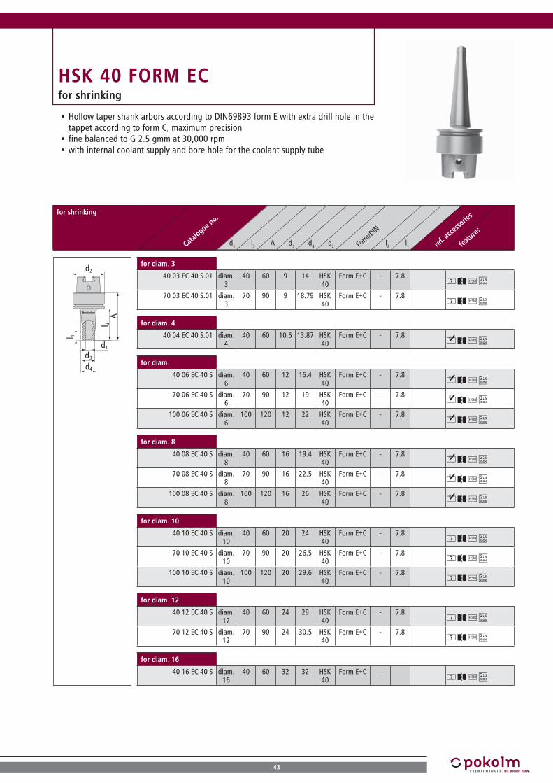
HSK 40 FORM ECfor shrinking
Hollow taper shank arbors according to DIN69893 form E with extra drill hole in the tappet according to form C, maximum precisionfine balanced to G 2.5 gmm at 30,000 rpmwith internal coolant supply and bore hole for the coolant supply tube
for shrinking
Catalogue n
o.
Form
/DIN
ref. a
ccesso
ries
features
d1 l3 A d3 d4 d2 l2 l1
Al 3
l 1
d2
d4
d3
d1
for diam. 3
40 03 EC 40 S.01 diam. 3
40 60 9 14 HSK 40
Form E+C - 7.8
70 03 EC 40 S.01 diam. 3
70 90 9 18.79 HSK 40
Form E+C - 7.8
for diam. 4
40 04 EC 40 S.01 diam. 4
40 60 10.5 13.87 HSK 40
Form E+C - 7.8
for diam.
40 06 EC 40 S diam. 6
40 60 12 15.4 HSK 40
Form E+C - 7.8
70 06 EC 40 S diam. 6
70 90 12 19 HSK 40
Form E+C - 7.8
100 06 EC 40 S diam. 6
100 120 12 22 HSK 40
Form E+C - 7.8
for diam. 8
40 08 EC 40 S diam. 8
40 60 16 19.4 HSK 40
Form E+C - 7.8
70 08 EC 40 S diam. 8
70 90 16 22.5 HSK 40
Form E+C - 7.8
100 08 EC 40 S diam. 8
100 120 16 26 HSK 40
Form E+C - 7.8
for diam. 10
40 10 EC 40 S diam. 10
40 60 20 24 HSK 40
Form E+C - 7.8
70 10 EC 40 S diam. 10
70 90 20 26.5 HSK 40
Form E+C - 7.8
100 10 EC 40 S diam. 10
100 120 20 29.6 HSK 40
Form E+C - 7.8
for diam. 12
40 12 EC 40 S diam. 12
40 60 24 28 HSK 40
Form E+C - 7.8
70 12 EC 40 S diam. 12
70 90 24 30.5 HSK 40
Form E+C - 7.8
for diam. 16
40 16 EC 40 S diam. 16
40 60 32 32 HSK 40
Form E+C - -

44
latest items! available as long as stock lasts on request stock item, subject to confirmation
HSK 50 FORM Efor screw-on end mills
for screw-on end mills
Catalogue n
o.
Form
/DIN
ref. a
ccesso
ries
features
d1 l3 A d3 d4 d2 l2 l1
A
d1
l 1
l 3
d2
d3
d4
M8
25 08 E50 M 8 25 51 13.8 15 HSK 50
form E - 12 A, B
50 08 E50 M 8 50 76 13.8 23 HSK 50
form E - 12 A, B
75 08 E50 M 8 75 101 13.8 25 HSK 50
form E - 12 A, B
100 08 E50 M 8 100 126 13.8 30 HSK 50
form E - 12 A, B
M10
25 10 E50 M 10 25 51 18 23 HSK 50
form E - 12 A, B
50 10 E50 M 10 50 76 18 25 HSK 50
form E - 12 A, B
75 10 E50 M 10 75 101 18 30 HSK 50
form E - 12 A, B
100 10 E50 M 10 100 126 18 35 HSK 50
form E - 12 A, B
M12
25 12 E50 M 12 25 51 21 24 HSK 50
form E - 12 A, B
50 12 E50 M 12 50 76 21 30 HSK 50
form E - 12 A, B
75 12 E50 M 12 75 101 21 35 HSK 50
form E - 12 A, B
100 12 E50 M 12 100 126 21 38 HSK 50
form E - 12 A, B
M16
25 16 E50 M 16 25 51 29 29 HSK 50
form E - - A, B
50 16 E50 M 16 50 76 29 34 HSK 50
form E - 12 A, B
75 16 E50 M 16 75 101 29 35 HSK 50
form E - 12 A, B
Accessories
KMR-50A
A > Page 125
SCHLUESSELHSK50
B > Page 125
Hollow taper shank arbors according to DIN69893 form E, maximum precisionfine balanced to G 2.5 gmm at 30,000 rpmwith internal coolant supply and bore hole for the coolant supply tube
HOLLOW TAPER SHANK HSK

45
HSK 50 FORM Efor shrinking
Hollow taper shank arbors according to DIN69893 form E, maximum precisionfine balanced to G 2.5 gmm at 30.000 rpmwith internal coolant supply and bore hole for the coolant supply tube
for shrinking
Catalogue n
o.
Form
/DIN
ref. a
ccesso
ries
features
d1 l3 A d3 d4 d2 l2 l1
Al 3
d2
l 1
d4
d3
d1
for diam. 3
50 03 E50 S.01 diam. 3
50 76 9 15.6 HSK 50
form E - 7.8 A, B
100 03 E50 S.01 diam. 3
100 126 9 23.51 HSK 50
form E - 7.8 A, B
for diam. 4
50 04 E50 S.01 diam. 4
50 76 10.5 14.92 HSK 50
form E - 7.8 A, B
100 04 E50 S.01 diam. 4
100 126 10.5 20.1 HSK 50
form E - 7.8 A, B
150 04 E50 S diam. 4
150 176 9 24 HSK 50
form E - 7.8 A, B
for diam. 6
50 06 E50 S diam. 6
50 76 12 16.4 HSK 50
form E - 7.8 A, B
100 06 E50 S diam. 6
100 126 12 21.6 HSK 50
form E - 7.8 A, B
150 06 E50 S diam. 6
150 176 12 27 HSK 50
form E - 7.8 A, B
for diam. 8
50 08 E50 S diam. 8
50 76 16 20.3 HSK 50
form E - 7.8 A, B
100 08 E50 S diam. 8
100 126 16 25.7 HSK 50
form E - 7.8 A, B
150 08 E50 S diam. 8
150 176 16 30.9 HSK 50
form E - 7.8 A, B
for diam. 10
50 10 E50 S diam. 10
50 76 20 24.4 HSK 50
form E - 7.8 A, B
100 10 E50 S diam. 10
100 126 20 30 HSK 50
form E - 7.8 A, B
for diam. 12
50 12 E50 S diam. 12
50 76 24 28.4 HSK 50
form E - 7.8 A, B
100 12 E50 S diam. 12
100 126 24 34 HSK 50
form E - 7.8 A, B
Accessories
KMR-50A
A > Page 125
SCHLUESSELHSK50
B > Page 125
1 / 2

46
latest items! available as long as stock lasts on request stock item, subject to confirmation
for shrinking
Catalogue n
o.
Form
/DIN
ref. a
ccesso
ries
features
d1 l3 A d3 d4 d2 l2 l1
Al 3
d2
l 1
d4
d3
d1
for diam. 16
50 16 E50 S diam. 16
50 76 32 36.4 HSK 50
form E - 7.8 A, B
100 16 E50 S diam. 16
100 126 32 40 HSK 50
form E - 7.8 A, B
for diam. 20
60 20 E50 S diam. 20
60 86 40 40 HSK 50
form E - - A, B
100 20 E50 S diam. 20
100 126 40 40 HSK 50
form E - - A, B
Accessories
KMR-50A
A > Page 125
SCHLUESSELHSK50
B > Page 125
Hollow taper shank arbors according to DIN69893 form E, maximum precisionfine balanced to G 2.5 gmm at 30,000 rpmwith internal coolant supply and bore hole for the coolant supply tube
HSK 50 FORM Efor shrinking
2 / 2
HOLLOW TAPER SHANK HSK

47
HSK 50 FORM EDrill chuck
Hollow taper shank arbor CNC precision drill chuck according to DIN69893 form E, maximum precisionapproved for up to max. 7,000 rpmWe can supply higher balance quality according to the balance classes upon requestwith internal coolant supply and bore hole for the coolant supply tubeindependent of rotating directionextremely short and slim design Scope of delivery includes small and large seal ring
Drill chuck
Catalogue n
o.
Form
/DIN
ref. a
ccesso
ries
features
d1 l3 A d3 d4 d2 l2 l1
Al 3
d2
d3/d4
d1
diam. 0.3 - 8 mm
BF 0.3-8 E50 IC diam. 8
72 98 - 36 HSK 50
form E - - A, C, D, E, F, K
diam. 0.5 - 13 mm
BF 0.5-13 E50 IC diam. 13
96 122 - 50 HSK 50
form E - - B, C, D, G, H, L
diam. 2.5 - 16 mm
BF 2.5-16 E50 IC diam. 16
101 127 - 57 HSK 50
form E - - B, C, D, I, J, L
Accessories
INBUS 4T
A > Page 125
INBUS 6T
B > Page 125
KMR-50A
C > Page 125
SCHLUESSELHSK50
D > Page 125
BF08DS04
E > Page 126
BF08DS08
F > Page 126
BF13DS06
G > Page 126
BF13DS13
H > Page 126
BF16DS06
I > Page 126
BF16DS16
J > Page 126
BF08MW
K > Page 126
BF13MW
L > Page 126
NEW

48
latest items! available as long as stock lasts on request stock item, subject to confirmation
HSK 50 FORM EHSC precision collet chucks
HSC precision collet chucks
Catalogue n
o.
Form
/DIN
ref. a
ccesso
ries
features
d1 l3 A d3 d4 d2 l2 l1
A
d2
l 3l 1
d4
d3
d1
for ER 20
50 ER20 E50 ER 20 50 76 28 32 HSK 50
form E - 33.8 A, B, C, D
Accessories
20 501
A > Page 124
ER20 001
B > Page 125
KMR-50A
C > Page 125
SCHLUESSELHSK50
D > Page 125
Hollow taper shank arbors according to DIN69893 form E, maximum precisionfine balanced to G 2.5 gmm at 30,000 rpmwith internal coolant supply and bore hole for the coolant supply line
HOLLOW TAPER SHANK HSK

49
HSK 63 FORM Afor screw-on end mills
Hollow taper shank arbors according to DIN69893 form A, maximum precisionfine balanced to G 6.3 gmm at 20,000 rpmwith internal coolant supply and bore hole for the coolant supply tube
for screw-on end mills
Catalogue n
o.
Form
/DIN
ref. a
ccesso
ries
features
d1 l3 A d3 d4 d2 l2 l1
A
l 1
d3
d1
l 3
d2
d4
M8
25 08 A63 M 8 25 51 13.8 15 HSK 63
form A - 12 A, B
50 08 A63 M 8 50 76 13.8 23 HSK 63
form A - 12 A, B
75 08 A63 M 8 75 101 13.8 25 HSK 63
form A - 12 A, B
100 08 A63 M 8 100 126 13.8 30 HSK 63
form A - 12 A, B
M10
25 10 A63 M 10 25 51 18 23 HSK 63
form A - 12 A, B
50 10 A63 M 10 50 76 18 25 HSK 63
form A - 12 A, B
75 10 A63 M 10 75 101 18 30 HSK 63
form A - 12 A, B
100 10 A63 M 10 100 126 18 35 HSK 63
form A - 12 A, B
125 10 A63 M 10 125 151 18 38 HSK 63
form A - 12 A, B
150 10 A63 M 10 150 176 18 45 HSK 63
form A - 12 A, B
M12
25 12 A63 M 12 25 51 21 24 HSK 63
form A - 12 A, B
50 12 A63 M 12 50 76 21 30 HSK 63
form A - 12 A, B
75 12 A63 M 12 75 101 21 35 HSK 63
form A - 12 A, B
100 12 A63 M 12 100 126 21 38 HSK 63
form A - 12 A, B
125 12 A63 M 12 125 151 21 43 HSK 63
form A - 12 A, B
150 12 A63 M 12 150 176 21 45 HSK 63
form A - 12 A, B
175 12 A63 M 12 175 201 21 50 HSK 63
form A - 12 A, B
Accessories
KMR-63A
A > Page 125
SCHLUESSELHSK63
B > Page 125
1 / 2

50
latest items! available as long as stock lasts on request stock item, subject to confirmation
for screw-on end mills
Catalogue n
o.
Form
/DIN
ref. a
ccesso
ries
features
d1 l3 A d3 d4 d2 l2 l1
A
l 1
d3
d1
l 3
d2
d4
M16
25 16 A63 M 16 25 51 29 29 HSK 63
form A - - A, B
50 16 A63 M 16 50 76 29 34 HSK 63
form A - 12 A, B
75 16 A63 M 16 75 101 29 35 HSK 63
form A - 12 A, B
100 16 A63 M 16 100 126 29 40 HSK 63
form A - 12 A, B
125 16 A63 M 16 125 151 29 44 HSK 63
form A - 12 A, B
150 16 A63 M 16 150 176 29 48 HSK 63
form A - 12 A, B
175 16 A63 M 16 175 201 29 50 HSK 63
form A - 12 A, B
200 16 A63 M 16 200 226 29 50 HSK 63
form A - 12 A, B
250 16 A63 M 16 250 276 29 50 HSK 63
form A - 12 A, B
Accessories
KMR-63A
A > Page 125
SCHLUESSELHSK63
B > Page 125
Hollow taper shank arbors according to DIN69893 form A, maximum precisionfine balanced to G 6.3 gmm at 20,000 rpmwith internal coolant supply and bore hole for the coolant supply tube
HSK 63 FORM Afor screw-on end mills
2 / 2
HOLLOW TAPER SHANK HSK

51
HSK 63 FORM Afor screw-on end mills | cylindrical
Hollow taper shank arbors according to DIN69893 form A, maximum precisionfine balanced to G 6.3 gmm at 20,000 rpmwith internal coolant supply and bore hole for the coolant supply tube
for screw-on end mills | cylindrical
Catalogue n
o.
Form
/DIN
ref. a
ccesso
ries
features
d1 l3 A d3 d4 d2 l2 l1
d2
d4
l 3
d3
d1
A
M8
50 08 A63 ZYL M 8 50 76 13.8 13.8 HSK 63
form A - - A, B
M10
50 10 A63 ZYL M 10 50 76 18 18 HSK 63
form A - - A, B
100 10 A63 ZYL M 10 100 126 18 18 HSK 63
form A - - A, B
M12
50 12 A63 ZYL M 12 50 76 21 21 HSK 63
form A - - A, B
100 12 A63 ZYL M 12 100 126 21 21 HSK 63
form A - - A, B
M16
50 16 A63 ZYL M 16 50 76 29 29 HSK 63
form A - - A, B
100 16 A63 ZYL M 16 100 126 29 29 HSK 63
form A - - A, B
Accessories
KMR-63A
A > Page 125
SCHLUESSELHSK63
B > Page 125

52
latest items! available as long as stock lasts on request stock item, subject to confirmation
HSK 63 FORM Afor shrinking
for shrinking
Catalogue n
o.
Form
/DIN
ref. a
ccesso
ries
features
d1 l3 A d3 d4 d2 l2 l1
A
l 1
d3
l 3
d2
d1
d4
for diam. 3
50 03 A63 S.01 diam. 3
50 76 9 15.6 HSK 63
form A - 7.8 A, B
100 03 A63 S.01 diam. 3
100 126 9 23.5 HSK 63
form A - 7.8 A, B
for diam. 4
50 04 A63 S.01 diam. 4
50 76 10.5 14.92 HSK 63
form A - 7.8 A, B
75 04 A63 S.01 diam. 4
75 101 10.5 17.54 HSK 63
form A - 7.8 A, B
100 04 A63 S.01 diam. 4
100 126 10.5 20.16 HSK 63
form A - 7.8 A, B
for diam. 6
50 06 A63 S diam. 6
50 76 12 16.4 HSK 63
form A - 7.8 A, B
75 06 A63 S diam. 6
75 101 12 19 HSK 63
form A - 7.8 A, B
100 06 A63 S diam. 6
100 126 12 21.7 HSK 63
form A - 7.8 A, B
for diam. 8
50 08 A63 S diam. 8
50 76 16 20.4 HSK 63
form A - 7.8 A, B
75 08 A63 S diam. 8
75 101 16 23 HSK 63
form A - 7.8 A, B
100 08 A63 S diam. 8
100 126 16 25.7 HSK 63
form A - 7.8 A, B
for diam. 10
50 10 A63 S diam. 10
50 76 20 24.4 HSK 63
form A - 7.8 A, B
75 10 A63 S diam. 10
75 101 20 27 HSK 63
form A - 7.8 A, B
100 10 A63 S diam. 10
100 126 20 30 HSK 63
form A - 7.8 A, B
150 10 A63 S diam. 10
150 176 20 35 HSK 63
form A - 7.8 A, B
200 10 A63 S diam. 10
200 226 20 40.1 HSK 63
form A - 7.8 A, B
Hollow taper shank arbors according to DIN69893 form A, maximum precisionfine balanced to G 6.3 gmm at 20,000 rpmwith internal coolant supply and bore hole for the coolant supply tube
1 / 2
HOLLOW TAPER SHANK HSK

53
for shrinking
Catalogue n
o.
Form
/DIN
ref. a
ccesso
ries
features
d1 l3 A d3 d4 d2 l2 l1
A
l 1
d3
l 3
d2
d1
d4
for diam. 12
50 12 A63 S diam. 12
50 76 24 28.4 HSK 63
form A - 7.8 A, B
75 12 A63 S diam. 12
75 101 24 31 HSK 63
form A - 7.8 A, B
100 12 A63 S diam. 12
100 126 24 33.7 HSK 63
form A - 7.8 A, B
for diam. 16
50 16 A63 S diam. 16
50 76 32 36.4 HSK 63
form A - 7.8 A, B
75 16 A63 S diam. 16
75 101 32 39 HSK 63
form A - 7.8 A, B
100 16 A63 S diam. 16
100 126 32 41.7 HSK 63
form A - 7.8 A, B
150 16 A63 S diam. 16
150 176 32 46.9 HSK 63
form A - 7.8 A, B
for diam. 20
60 20 A63 S diam. 20
60 86 40 45.5 HSK 63
form A - 7.8 A, B
100 20 A63 S diam. 20
100 126 40 49.7 HSK 63
form A - 7.8 A, B
for diam. 25
60 25 A63 S diam. 25
60 86 46 46 HSK 63
form A - - A, B
Accessories
KMR-63A
A > Page 125
SCHLUESSELHSK63
B > Page 125
2 / 2

54
latest items! available as long as stock lasts on request stock item, subject to confirmation
HSK 63 FORM Afor shrinking | reinforced design
for shrinking | reinforced design
Catalogue n
o.
Form
/DIN
ref. a
ccesso
ries
features
d1 l3 A d3 d4 d2 l2 l1
A
l 1
d3
l 3
d2
d1
d4
for diam. 6
50 06 A63 SB diam. 6
50 76 21 27.6 HSK 63
form A - 7.8 A, B
100 06 A63 SB diam. 6
100 126 21 35.5 HSK 63
form A - 7.8 A, B
for diam. 8
50 08 A63 SB diam. 8
50 76 21 27.6 HSK 63
form A - 7.8 A, B
100 08 A63 SB diam. 8
100 126 21 35.5 HSK 63
form A - 7.8 A, B
for diam. 10
50 10 A63 SB diam. 10
50 76 24 30.6 HSK 63
form A - 7.8 A, B
100 10 A63 SB diam. 10
100 126 24 38.5 HSK 63
form A - 7.8 A, B
Accessories
KMR-63A
A > Page 125
SCHLUESSELHSK63
B > Page 125
Hollow taper shank arbors according to DIN69893 form A, maximum precisionfine balanced to G 6.3 gmm at 20,000 rpmwith internal coolant supply and bore hole for the coolant supply tube
HOLLOW TAPER SHANK HSK

55
HSK 63 FORM Afor shell-type milling
Hollow taper shank arbors according to DIN69893 form A, maximum precisionfine balanced to G 6.3 gmm at 20,000 rpmwith internal coolant supply and bore hole for the coolant supply tube
for shell-type milling
Catalogue n
o.
Form
/DIN
ref. a
ccesso
ries
features
d1 l3 A d3 d4 d2 l2 l1
A
l 1
d4
d3
l 3
d1
d1
bore diam. 16
25 16 A63 Z diam. 16
25 51 38 40 HSK 63
form A - 7.8 C, D, G, H
50 16 A63 Z diam. 16
50 76 38 42 HSK 63
form A - 7.8 C, D, G, H
75 16 A63 Z diam. 16
75 101 38 45 HSK 63
form A - 7.8 C, D, G, H
100 16 A63 Z diam. 16
100 126 38 50 HSK 63
form A - 7.8 C, D, G, H
125 16 A63 Z diam. 16
125 151 38 50 HSK 63
form A - 7.8 C, D, G, H
150 16 A63 Z diam. 16
150 176 38 50 HSK 63
form A - 7.8 C, D, G, H
175 16 A63 Z diam. 16
175 201 38 50 HSK 63
form A - 7.8 C, D, G, H
200 16 A63 Z diam. 16
200 226 38 50 HSK 63
form A - 7.8 C, D, G, H
25 22 A63 diam. 22
25 51 40 40 HSK 63
form A - - B, E, G, H
50 22 A63 diam. 22
50 76 40 40 HSK 63
form A - - B, E, G, H
75 22 A63.01 diam. 22
75 101 48 50 HSK 63
form A - 7.8 B, E, G, H
100 22 A63.01 diam. 22
100 126 48 50 HSK 63
form A - 7.8 B, E, G, H
150 22 A63 diam. 22
150 176 48 48 HSK 63
form A - - B, E, G, H
Accessories
M5X12
A > Page 124
M4X10
B > Page 124
M3X10
C > Page 124
NUTEN8X8
D > Page 125
NUTEN10X8 E > Page 125
NUTEN12X8 F > Page 125
KMR-63A
G > Page 125
SCHLUESSELHSK63
H > Page 125
1 / 2

56
latest items! available as long as stock lasts on request stock item, subject to confirmation
for shell-type milling
Catalogue n
o.
Form
/DIN
ref. a
ccesso
ries
features
d1 l3 A d3 d4 d2 l2 l1
A
l 1
d4
d3
l 3
d1
d1
bore diam. 27
25 27 A63 diam. 27
25 51 48 48 HSK 63
form A - - A, F, G, H
50 27 A63 diam. 27
50 76 48 48 HSK 63
form A - - A, F, G, H
75 27 A63 diam. 27
75 101 48 48 HSK 63
form A - - A, F, G, H
100 27 A63 diam. 27
100 126 48 48 HSK 63
form A - - A, F, G, H
Accessories
M5X12
A > Page 124
M4X10
B > Page 124
M3X10
C > Page 124
NUTEN8X8
D > Page 125
NUTEN10X8 E > Page 125
NUTEN12X8 F > Page 125
KMR-63A
G > Page 125
SCHLUESSELHSK63
H > Page 125
Hollow taper shank arbors according to DIN69893 form A, maximum precisionfine balanced to G 6.3 gmm at 20,000 rpmwith internal coolant supply and bore hole for the coolant supply line
HSK 63 FORM Afor shell-type milling
2 / 2
HOLLOW TAPER SHANK HSK

57
HSK 63 FORM ADrill chuck
Hollow taper shank arbors CNC precision drill chuck according to DIN69893 form E, maximum precisionapproved for up to max. 7,000 rpmWe can supply higher balance quality according to the balance classes upon requestwith internal coolant supply and bore hole for the coolant supply tubeindependent of rotating directionextremely short and slim design Scope of delivery includes small and large seal ring
Drill chuck
Catalogue n
o.
Form
/DIN
ref. a
ccesso
ries
features
d1 l3 A d3 d4 d2 l2 l1
Al 3
d2
d3/d4
d1
diam. 0.3 - 8 mm
BF 0,3-8 A63 IC diam. 8
73 99 - 36 HSK 63
form A - - A, C, D, E, F, K
diam. 0.5 - 13 mm
BF 0,5-13 A63 IC diam. 13
84 110 - 50 HSK 63
form A - - B, C, D, G, H, L
diam. 2.5 - 16 mm
BF 2,5-16 A63 IC diam. 16
89 115 - 57 HSK 63
form A - - B, C, D, I, J, L
Accessories
INBUS 4T
A > Page 125
INBUS 6T
B > Page 125
KMR-63A
C > Page 125
SCHLUESSELHSK63
D > Page 125
BF08DS04
E > Page 126
BF08DS08
F > Page 126
BF13DS06
G > Page 126
BF13DS13
H > Page 126
BF16DS06
I > Page 126
BF16DS16
J > Page 126
BF08MW
K > Page 126
BF13MW
L > Page 126
NEW

58
latest items! available as long as stock lasts on request stock item, subject to confirmation
HSK 63 FORM Afor morse tappets
for morse tappets
Catalogue n
o.
Form
/DIN
ref. a
ccesso
ries
features
d1 l3 A d3 d4 d2 l2 l1
d2
l 3
l 1
d4
d3d1
A
MTS 2
100 MK2 AL A63 MTS 2
100 126 30 44 HSK 63
form A - 7.8 A, B
MTS 3
120 MK3 AL A63 MTS 3
120 146 35 46 HSK 63
form A - 7.8 A, B
Accessories
KMR-63A
A > Page 125
SCHLUESSELHSK63
B > Page 125
Hollow taper shank arbors according to DIN69893 form A, maximum precisionfine balanced to G 6.3 gmm at 20,000 rpmwith internal coolant supply and bore hole for the coolant supply tube
HOLLOW TAPER SHANK HSK

59
HSK 63 FORM AHSC precision collet chucks
Hollow taper shank arbors according to DIN69893 form A, maximum precisionfine balanced to G 6.3 gmm at 20,000 rpmwith internal coolant supply and bore hole for the coolant supply tube
HSC precision collet chucks
Catalogue n
o.
Form
/DIN
ref. a
ccesso
ries
features
d1 l3 A d3 d4 d2 l2 l1
A
d2
l 3l 1
d4
d3
d1
for ER 20
50 ER20 A63 ER 20 50 76 28 32 HSK 63
form A - 33.8 A, B, C, D
100 ER20 A63 ER 20 100 126 28 40 HSK 63
form A - 33.8 A, B, C, D
Accessories
20 501
A > Page 124
ER20 001
B > Page 125
KMR-63A
C > Page 125
SCHLUESSELHSK63
D > Page 125

60
latest items! available as long as stock lasts on request stock item, subject to confirmation
HSK63 FORM Afor rotary transmission leadthrough
for rotary transmission leadthrough
Catalogue n
o.
Form
/DIN
ref. a
ccesso
ries
features
d1 l3 A d3 d4 d2 l2 l1
A d4
d2
l 1 l 3
d3
d1
A
l 3l 1
d4
d3
d2
d1
for threaded shank milling
30 16 A63 DDLS M 16 30 56 29 32 HSK 63
form A - 8 A, B
30 12 A63 DDLS M 12 30 56 21 25 HSK 63
form A - 8 A, B
for shell-type milling
30 22 A63 DDLS diam. 22
30 56 48 50 HSK 63
form A - - A, B
Accessories
KMR-63A
A > Page 125
SCHLUESSELHSK63
B > Page 125
Hollow taper shank arbor rotary transmission leadthrough DIN69893 form Aapproved for up to max. 6,000 rpmsuitable for oiled compressed air and minimum quantity lubricationindependent of rotating direction
HOLLOW TAPER SHANK HSK NEW

61
HSK 100 FORM Afor screw-on end mills
Hollow taper shank arbors according to DIN69893 form A, maximum precisionfine balanced to G 16 gmm at 8,000 rpmwith internal coolant supply and bore hole for the coolant supply tube
for screw-on end mills
Catalogue n
o.
Form
/DIN
ref. a
ccesso
ries
features
d1 l3 A d3 d4 d2 l2 l1
A
l 1
d3
d1
l 3
d2
d4
M8
50 08 A100 M 8 50 79 13.8 23 HSK 100
form A - 12 A, B
100 08 A100 M 8 100 129 13.8 30 HSK 100
form A - 12 A, B
M10
50 10 A100 M 10 50 79 18 25 HSK 100
form A - 12 A, B
75 10 A100 M 10 75 104 18 30 HSK 100
form A - 12 A, B
100 10 A100 M 10 100 129 18 35 HSK 100
form A - 12 A, B
150 10 A100 M 10 150 179 18 45 HSK 100
form A - 12 A, B
M12
50 12 A100 M 12 50 79 21 30 HSK 100
form A - 12 A, B
100 12 A100 M 12 100 129 21 38 HSK 100
form A - 12 A, B
150 12 A100 M 12 150 179 21 52 HSK 100
form A - 12 A, B
200 12 A100 M 12 200 229 21 58 HSK 100
form A - 12 A, B
M16
50 16 A100 M 16 50 79 29 34 HSK 100
form A - 12 A, B
100 16 A100 M 16 100 129 29 40 HSK 100
form A - 12 A, B
150 16 A100 M 16 150 179 29 58 HSK 100
form A - 12 A, B
200 16 A100 M 16 200 229 29 58 HSK 100
form A - 12 A, B
250 16 A100 M 16 250 279 29 66 HSK 100
form A - 12 A, B
300 16 A100 M 16 300 329 29 66 HSK 100
form A - 12 A, B
Accessories
KMR-100A
A > Page 125
SCHLUESSELHSK100
B > Page 125

62
latest items! available as long as stock lasts on request stock item, subject to confirmation
HSK 100 FORM Afor shrinking
for shrinking
Catalogue n
o.
Form
/DIN
ref. a
ccesso
ries
features
d1 l3 A d3 d4 d2 l2 l1
A
l 1
d3
l 3
d2
d1
d4
for diam. 6
100 06 A100 S diam. 6
100 129 12 22 HSK 100
form A - 7.8 A, B
for diam. 8
100 08 A100 S diam. 8
100 129 16 25.7 HSK 100
form A - 7.8 A, B
for diam. 10
100 10 A100 S diam. 10
100 129 20 29.7 HSK 100
form A - 7.8 A, B
for diam. 12
100 12 A100 S diam. 12
100 129 24 33.7 HSK 100
form A - 7.8 A, B
for diam. 16
60 16 A100 S diam. 16
60 89 32 37.5 HSK 100
form A - 7.8 A, B
for diam. 20
60 20 A100 S diam. 20
60 89 40 45.5 HSK 100
form A - 7.8 A, B
for diam. 25
60 25 A100 S diam. 25
60 89 46 46 HSK 100
form A - 7.8 A, B
Accessories
KMR-100A
A > Page 125
SCHLUESSELHSK100
B > Page 125
Hollow taper shank arbors according to DIN69893 form A, maximum precisionfine balanced to G 16 gmm at 8,000 rpmwith internal coolant supply and bore hole for the coolant supply tube
HOLLOW TAPER SHANK HSK NEW

63
HSK 100 FORM Afor shell-type milling
Hollow taper shank arbors according to DIN69893 form A, maximum precisionfine balanced to G 16 gmm at 8,000 rpmwith internal coolant supply and bore hole for the coolant supply tube
for shell-type milling
Catalogue n
o.
Form
/DIN
ref. a
ccesso
ries
features
d1 l3 A d3 d4 d2 l2 l1
A
l 1
d4
d3
l 3
d1
d1
bore diam. 22
50 22 A100 diam. 22
50 79 40 40 HSK 100
form A - - A, C, F, G
75 22 A100 diam. 22
75 104 48 48 HSK 100
form A - - A, C, F, G
100 22 A100 diam. 22
100 129 48 50 HSK 100
form A - 7.8 A, C, F, G
150 22 A100 diam. 22
150 179 48 50 HSK 100
form A - 7.8 A, C, F, G
200 22 A100 diam. 22
200 229 48 50 HSK 100
form A - 7.8 A, C, F, G
bore diam. 27
50 27 A100 diam. 27
50 79 62 62 HSK 100
form A - - B, D, F, G
100 27 A100 diam. 27
100 129 62 71 HSK 100
form A - 7.8 B, D, F, G
150 27 A100 diam. 27
150 179 62 80 HSK 100
form A - 7.8 B, D, F, G
200 27 A100 diam. 27
200 229 62 80 HSK 100
form A - 7.8 B, D, F, G
bore diam. 32
50 32 A100 diam. 32
50 79 85 85 HSK 100
form A - - B, E, F, G
100 32 A100 diam. 32
100 129 85 85 HSK 100
form A - - B, E, F, G
150 32 A100 diam. 32
150 179 85 85 HSK 100
form A - - B, E, F, G
Accessories
M4X10
A > Page 124
M5X16
B > Page 124
NUTEN10X8
C > Page 125
NUTEN12X12/2 D > Page 125
NUTEN14X14 E > Page 125
KMR-100A
F > Page 125
SCHLUESSELHSK100
G > Page 125

64
latest items! available as long as stock lasts on request stock item, subject to confirmation
HSK 100 FORM ADrill chuck
Drill chuck
Catalogue n
o.
Form
/DIN
ref. a
ccesso
ries
features
d1 l3 A d3 d4 d2 l2 l1
Al 3
d2
d3/d4
d1
diam. 0.5 - 13 mm
BF 0,5-13 A100 IC diam. 13
89 118 - 50 HSK 100
form A - - A, B, C, D, E, H
diam. 2.5 - 16 mm
BF 2,5-16 A100 IC diam. 16
83 112 - 57 HSK 100
form A - - A, B, C, F, G, H
Accessories
INBUS 6T
A > Page 125
KMR-100A
B > Page 125
SCHLUESSELHSK100
C > Page 125
BF13DS06
D > Page 126
BF13DS13
E > Page 126
BF16DS06
F > Page 126
BF16DS16
G > Page 126
BF13MW
H > Page 126
Hollow taper shank arbor CNC precision drill chuck according to DIN69893 form E, maximum precisionapproved for up to max. 7,000 rpmWe can supply higher balance quality according to the balance classes upon requestwith internal coolant supply and bore hole for the coolant supply tubeindependent of rotating directionextremely short and slim design Scope of delivery includes small and large seal ring
HOLLOW TAPER SHANK HSK NEW

65
Page
SK 30 DIN 69871 AD for screw-on end mills 66
for shrinking 67
for shrinking | zero reach adapters 68
HSC precision collet chucks 69
BT 30 JIS B 6339 AD for screw-on end mills 70
for shrinking 71
for shrinking | zero reach adapters 72
HSC precision collet chucks 73
SK 40 DIN 69 871 AD for screw-on end mills 74
for screw-on end mills | cylindrical 76
for shrinking 77
for shrinking | reinforced design 79
for shrinking | zero reach adapters 80
for shell-type milling 81
Drill chuck 83
HSC precision collet chucks 84
for rotary transmission leadthrough 85
BT 40 JIS B 6339 AD for screw-on end mills 86
for screw-on end mills | cylindrical 87
for shrinking 88
for shrinking | zero reach arbors 90
for shell-type milling 91
HSC precision collet chucks 92
for rotary transmission leadthrough 93
SK 50 DIN 69 871 AD for screw-on end mills 94
For shrinking 95
for shrinking | zero reach arbors 97
for shell-type milling 98
Drill chucks 100
for more tappets 101
for rotary transmission leadthrough 103
BT 50 JIS B 6339 AD for screw-on end mills 104
for shrinking 105
for shrinking | zero reach arbors 107
for shell-type milling 108
for rotary transmission leadthrough 109
STEEP TAPER SHANKS SK / BTSTEEP TAPER SHANKS SK / BT

66
latest items! available as long as stock lasts on request stock item, subject to confirmation
SK 30 DIN 69871 ADfor screw-on end mills
for screw-on end mills
Catalogue n
o.
Form
/DIN
ref. a
ccesso
ries
features
d1 l3 A d3 d4 d2 l2 l1
d1
l 1
l 3
d2
d3
d4
A
M8
25 08 730 M 8 25 44.1 13.8 15 SK 30 DIN 69871 AD
- 12
M10
25 10 730 M 10 25 44.1 18 23 SK 30 DIN 69871 AD
- 12
M12
25 12 730 M 12 25 44.1 21 24 SK 30 DIN 69871 AD
- 12
M16
25 16 730 M 16 25 44.1 29 29 SK 30 DIN 69871 AD
- -
Steep taper shanks DIN 69871 AD, maximum precisionbalanced to G 2.5 ggm at 30,000 rpm
STEEP TAPER SHANKS SK / BT NEW

67
SK 30 DIN 69871 ADfor shrinking
Steep-angle tappet arbors DIN 69871 AD, maximum precisionbalanced to G 2.5 gmm at 30,000 rpm
for shrinking
Catalogue n
o.
Form
/DIN
ref. a
ccesso
ries
features
d1 l3 A d3 d4 d2 l2 l1
l 1
d1
d3
l 3A
d2
d4
for diam. 3
50 03 730 S.01 diam. 3
50 69.1 9 15.7 SK 30 DIN 69871 AD
- 7.8
for diam. 4
50 04 730 S.01 diam. 4
50 69.1 10.5 14.9 SK 30 DIN 69871 AD
- 7.8
for diam. 6
50 06 730 S diam. 6
50 69.1 12 16.4 SK 30 DIN 69871 AD
- 7.8
for diam. 8
50 08 730 S diam. 8
50 69.1 16 20.4 SK 30 DIN 69871 AD
- 7.8
for diam. 10
50 10 730 S diam. 10
50 69.1 20 24.4 SK 30 DIN 69871 AD
- 7.8
for diam. 12
50 12 730 S diam. 12
50 69.1 24 28.4 SK 30 DIN 69871 AD
- 7.8
for diam. 16
50 16 730 S diam. 16
50 69.1 32 36.4 SK 30 DIN 69871 AD
- 7.8
NEW

68
latest items! available as long as stock lasts on request stock item, subject to confirmation
SK 30 DIN 69871 ADfor shrinking | zero reach adapters
for shrinking | zero reach adapters
Catalogue n
o.
Form
/DIN
ref. a
ccesso
ries
features
d1 l3 A d3 d4 d2 l2 l1
A
d1
d3/d4
d2
for diam. 16
15 16 730 S diam. 16
15 34.1 32 32 SK 30 DIN 69871 AD
- -
for diam. 20
15 20 730 S diam. 20
15 34.1 40 40 SK 30 DIN 69871 AD
- -
Steep taper shanks DIN 69871 AD, maximum precisionbalanced to G 2.5 gmm at 30,000 rpm
Please note: Zero reach adapters cannot be ordered separately. We only supply in a shrink-grip connection with a solid carbide or dense antivibration adap-ters. (starting on page 19)
STEEP TAPER SHANKS SK / BT NEW

69
SK 30 DIN 69871 ADHSC precision collet chucks
Steep taper shanks DIN 69871 AD, maximum precisionbalanced to G 2.5 gmm at 30,000 rpm
HSC precision collet chucks
Catalogue n
o.
Form
/DIN
ref. a
ccesso
ries
features
d1 l3 A d3 d4 d2 l2 l1
A
d2
l 3l 1
d4
d3
d1
for ER 20
50 ER20 730 ER 20 50 69.1 28 32 SK 30 DIN 69871 AD
- 19.3 A, B
Accessories
20 501
A > Page 124
ER20 001
B > Page 125
NEW

70
latest items! available as long as stock lasts on request stock item, subject to confirmation
BT 30 JIS B 6339 ADfor threaded shank milling
for threaded shank milling
Catalogue n
o.
Form
/DIN
ref. a
ccesso
ries
features
d1 l3 A d3 d4 d2 l2 l1
A
d1
d3
d2
l 1
l 3
d4
M8
25 08 734 M 8 25 47 13.8 15 BT 30 JIS B 6339 AD
- 12
M10
25 10 734 M 10 25 47 18 23 BT 30 JIS B 6339 AD
- 12
M12
25 12 734 M 12 25 47 21 24 BT 30 JIS B 6339 AD
- 12
M16
25 16 734 M 16 25 47 29 29 BT 30 JIS B 6339 AD
- 12
Steep-angle tappet arbors form BT / JIS B 6339 AD, maximum precisionbalanced to G 2.5 gmm at 30,000 rpm
STEEP TAPER SHANKS SK / BT NEW

71
BT 30 JIS B 6339 ADfor shrinking
Steep taper shanks form BT / JIS B 6339 AD, maximum precisionbalanced to G 2.5 gmm at 30,000 rpm
for shrinking
Catalogue n
o.
Form
/DIN
ref. a
ccesso
ries
features
d1 l3 A d3 d4 d2 l2 l1
A
l 1
l 3
d2
d3
d1
d4
for diam. 3
50 03 734 S.01 diam. 3
50 72 9 15.6 BT 30 JIS B 6339 AD
- 7.8
for diam. 4
50 04 734 S.01 diam. 4
50 72 10.5 14.9 BT 30 JIS B 6339 AD
- 7.8
for diam. 6
50 06 734 S diam. 6
50 72 12 16 BT 30 JIS B 6339 AD
- 7.8
for diam. 8
50 08 734 S diam. 8
50 72 16 21 BT 30 JIS B 6339 AD
- 7.8
for diam. 10
50 10 734 S diam. 10
50 72 20 24.4 BT 30 JIS B 6339 AD
- 7.8
for diam. 12
50 12 734 S diam. 12
50 72 24 29 BT 30 JIS B 6339 AD
- 7.8
for diam. 16
50 16 734 S diam. 16
50 72 32 36.4 BT 30 JIS B 6339 AD
- 7.8
NEW

72
latest items! available as long as stock lasts on request stock item, subject to confirmation
BT 30 JIS B 6339 ADfor shrinking | zero reach adapters
for shrinking | zero reach adapters
Catalogue n
o.
Form
/DIN
ref. a
ccesso
ries
features
d1 l3 A d3 d4 d2 l2 l1
A
d3/d4
l 3
d2
d1
for diam. 16
10 16 734 S diam. 16
10 32 32 32 BT 30 JIS B 6339 AD
- -
for diam. 20
15 20 734 S diam. 20
15 37 40 40 BT 30 JIS B 6339 AD
- -
Steep taper shanks form BT / JIS B 6339 AD, maximum precisionbalanced to G 2.5 gmm at 30,000 rpm
Please note: Zero reach adapters cannot be ordered separately. We only supply in a shrink-grip connection with a solid carbide or dense antivibration adap-ters. (starting on page 19)
STEEP TAPER SHANKS SK / BT NEW

73
BT 30 JIS B 6339 ADHSC precision collet chucks
Steep taper shanks form BT / JIS B 6339 AD, maximum precisionbalanced to G 2.5 gmm at 30,000 rpm
HSC precision collet chucks
Catalogue n
o.
Form
/DIN
ref. a
ccesso
ries
features
d1 l3 A d3 d4 d2 l2 l1
A
d2
l 3l 1
d3
d4
d1
for ER 20
50 ER20 734 ER 20 50 72 28 32 BT 30 JIS B 6339 AD
- 19.3 A, B
Accessories
20 501
A > Page 124
ER20 001
B > Page 125
NEW

74
latest items! available as long as stock lasts on request stock item, subject to confirmation
SK 40 DIN 69 871 ADfor screw-on end mills
for screw-on end mills
Catalogue n
o.
Form
/DIN
ref. a
ccesso
ries
atures
d1 l3 A d3 d4 d2 l2 l1
d1
l 1
l 3
d2
d3
d4
A
M8
25 08 750 M 8 25 44.1 13.8 15 SK 40 DIN 69871 AD
- 12 A, B
50 08 750 M 8 50 69.1 13.8 23 SK 40 DIN 69871 AD
- 12 A, B
75 08 750 M 8 75 94.1 13.8 25 SK 40 DIN 69871 AD
- 12 A, B
100 08 750 M 8 100 119.1 13.8 30 SK 40 DIN 69871 AD
- 12 A, B
M10
25 10 750 M 10 25 44.1 18 23 SK 40 DIN 69871 AD
- 12 A, B
50 10 750 M 10 50 69.1 18 25 SK 40 DIN 69871 AD
- 12 A, B
75 10 750 M 10 75 94.1 18 30 SK 40 DIN 69871 AD
- 12 A, B
100 10 750 M 10 100 119.1 18 35 SK 40 DIN 69871 AD
- 12 A, B
125 10 750 M 10 125 144.1 18 40 SK 40 DIN 69871 AD
- 12 A, B
150 10 750 M 10 150 169.1 18 45 SK 40 DIN 69871 AD
- 12 A, B
M12
25 12 750 M 12 25 44.1 21 24 SK 40 DIN 69871 AD
- 12 A, B
50 12 750 M 12 50 69.1 21 30 SK 40 DIN 69871 AD
- 12 A, B
75 12 750 M 12 75 94.1 21 35 SK 40 DIN 69871 AD
- 12 A, B
100 12 750 M 12 100 119.1 21 38 SK 40 DIN 69871 AD
- 12 A, B
125 12 750 M 12 125 144.1 21 44 SK 40 DIN 69871 AD
- 12 A, B
150 12 750 M 12 150 169.1 21 48 SK 40 DIN 69871 AD
- 12 A, B
Steep taper shanks DIN 69871 AD, maximum precisionbalanced to G 6.3 gmm at 18,000 rpm
1 / 2
STEEP TAPER SHANKS SK / BT

75
for screw-on end mills
Catalogue n
o.
Form
/DIN
ref. a
ccesso
ries
atures
d1 l3 A d3 d4 d2 l2 l1
d1
l 1
l 3
d2
d3
d4
AM16
25 16 750 M 16 25 44.1 29 29 SK 40 DIN 69871 AD
- - A, B
50 16 750 M 16 50 69.1 29 34 SK 40 DIN 69871 AD
- 12 A, B
75 16 750 M 16 75 94.1 29 35 SK 40 DIN 69871 AD
- 12 A, B
100 16 750 M 16 100 119.1 29 40 SK 40 DIN 69871 AD
- 12 A, B
125 16 750 M 16 125 144.1 29 44 SK 40 DIN 69871 AD
- 12 A, B
150 16 750 M 16 150 169.1 29 48 SK 40 DIN 69871 AD
- 12 A, B
200 16 750 M 16 200 219.1 29 48 SK 40 DIN 69871 AD
- 12 A, B
250 16 750 M 16 250 269.1 29 48 SK 40 DIN 69871 AD
- 12 A, B
Accessories
KBSK40-69872A
A > Page 125
KBSK40-69872B
B > Page 126
2 / 2

76
latest items! available as long as stock lasts on request stock item, subject to confirmation
SK 40 DIN 69 871 ADfor screw-on end mills | cylindrical
for screw-on end mills | cylindrical
Catalogue n
o.
Form
/DIN
ref. a
ccesso
ries
features
d1 l3 A d3 d4 d2 l2 l1
d4
l 3
d1
d3
d2
A
M8
50 08 750 ZYL M 8 50 69.1 13.8 13.8 SK 40 DIN 69871 AD
- - A, B
M10
50 10 750 ZYL M 10 50 69.1 18 18 SK 40 DIN 69871 AD
- - A, B
75 10 750 ZYL M 10 75 94.1 18 18 SK 40 DIN 69871 AD
- - A, B
100 10 750 ZYL M 10 100 119.1 18 18 SK 40 DIN 69871 AD
- - A, B
M12
50 12 750 ZYL M 12 50 69.1 21 21 SK 40 DIN 69871 AD
- - A, B
75 12 750 ZYL M 12 75 94.1 21 21 SK 40 DIN 69871 AD
- - A, B
100 12 750 ZYL M 12 100 119.1 21 21 SK 40 DIN 69871 AD
- - A, B
M16
50 16 750 ZYL M 16 50 69.1 29 29 SK 40 DIN 69871 AD
- - A, B
75 16 750 ZYL M 16 75 94.1 29 29 SK 40 DIN 69871 AD
- - A, B
100 16 750 ZYL M 16 100 119.1 29 29 SK 40 DIN 69871 AD
- - A, B
Accessories
KBSK40-69872A
A > Page 125
KBSK40-69872B
B > Page 126
Steep taper shanks DIN 69871 AD, maximum precisionbalanced to G 6.3 gmm at 18,000 rpm
STEEP TAPER SHANKS SK / BT

77
SK 40 DIN 69 871 ADfor shrinking
Steep taper shanks DIN 69871 AD, maximum precisionbalanced to G 6.3 gmm at 18,000 rpm
for shrinking
Catalogue n
o.
Form
/DIN
ref. a
ccesso
ries
features
d1 l3 A d3 d4 d2 l2 l1
l 1
d1
d3
l 3A
d2
d4
for diam. 3
50 03 750 S.01 diam. 3
50 69.1 9 15.6 SK 40 DIN 69871 AD
- 7.8 A, B
100 03 750 S.01 diam. 3
100 119.1 9 23.5 SK 40 DIN 69871 AD
- 7.8 A, B
for diam. 4
50 04 750 S.01 diam. 4
50 69.1 10.5 14.9 SK 40 DIN 69871 AD
- 7.8 A, B
75 04 750 S.01 diam. 4
75 94.1 10.5 17.54 SK 40 DIN 69871 AD
- 7.8 A, B
100 04 750 S.01 diam. 4
100 119.1 10.5 20.16 SK 40 DIN 69871 AD
- 7.8 A, B
for diam. 6
50 06 750 S diam. 6
50 69.1 12 16.4 SK 40 DIN 69871 AD
- 7.8 A, B
75 06 750 S diam. 6
75 94.1 12 19 SK 40 DIN 69871 AD
- 7.8 A, B
100 06 750 S diam. 6
100 119.1 12 21.7 SK 40 DIN 69871 AD
- 7.8 A, B
for diam. 8
50 08 750 S diam. 8
50 69.1 16 20.4 SK 40 DIN 69871 AD
- 7.8 A, B
75 08 750 S diam. 8
75 94.1 16 23 SK 40 DIN 69871 AD
- 7.8 A, B
100 08 750 S diam. 8
100 119.1 16 25.7 SK 40 DIN 69871 AD
- 7.8 A, B
for diam. 10
50 10 750 S diam. 10
50 69.1 20 24.4 SK 40 DIN 69871 AD
- 7.8 A, B
75 10 750 S diam. 10
75 94.1 20 27 SK 40 DIN 69871 AD
- 7.8 A, B
100 10 750 S diam. 10
100 119.1 20 29.7 SK 40 DIN 69871 AD
- 7.8 A, B
Accessories
KBSK40-69872A
A > Page 125
KBSK40-69872B
B > Page 126
1 / 2

78
latest items! available as long as stock lasts on request stock item, subject to confirmation
for shrinking
Catalogue n
o.
Form
/DIN
ref. a
ccesso
ries
features
d1 l3 A d3 d4 d2 l2 l1
l 1
d1
d3
l 3A
d2
d4
for diam. 12
50 12 750 S diam. 12
50 69.1 24 28.4 SK 40 DIN 69871 AD
- 7.8 A, B
75 12 750 S diam. 12
75 94.1 24 31 SK 40 DIN 69871 AD
- 7.8 A, B
100 12 750 S diam. 12
100 119.1 24 33.6 SK 40 DIN 69871 AD
- 7.8 A, B
for diam. 16
50 16 750 S diam. 16
50 69.1 32 36.4 SK 40 DIN 69871 AD
- 7.8 A, B
75 16 750 S diam. 16
75 94.1 32 39 SK 40 DIN 69871 AD
- 7.8 A, B
100 16 750 S diam. 16
100 119.1 32 41.7 SK 40 DIN 69871 AD
- 7.8 A, B
for diam. 20
50 20 750 S diam. 20
50 69.1 40 44.4 SK 40 DIN 69871 AD
- 7.8 A, B
75 20 750 S diam. 20
75 94.1 40 47 SK 40 DIN 69871 AD
- 7.8 A, B
100 20 750 S diam. 20
100 119.1 40 49 SK 40 DIN 69871 AD
- 7.8 A, B
for diam. 25
60 25 750 S diam. 25
60 79.1 45 45 SK 40 DIN 69871 AD
- - A, B
Accessories
KBSK40-69872A
A > Page 125
KBSK40-69872B
B > Page 126
Steep taper shanks DIN 69871 AD, maximum precisionbalanced to G 6.3 gmm at 18,000 rpm
SK 40 DIN 69 871 ADfor shrinking
2 / 2
STEEP TAPER SHANKS SK / BT

79
SK 40 DIN 69 871 ADfor shrinking | reinforced design
Steep taper shanks DIN 69871 AD, maximum precisionbalanced to G 6.3 ggm at 18,000 rpm
for shrinking | reinforced design
Catalogue n
o.
Form
/DIN
ref. a
ccesso
ries
features
d1 l3 A d3 d4 d2 l2 l1
l 1 l 3A
d2
d3
d1
d4
for diam. 6
50 06 750 SB diam. 6
50 69.1 21 27.6 SK 40 DIN 69871 AD
- 7.8 A, B
100 06 750 SB diam. 6
100 119.1 21 35.5 SK 40 DIN 69871 AD
- 7.8 A, B
for diam. 8
50 08 750 SB diam. 8
50 69.1 21 27.6 SK 40 DIN 69871 AD
- 7.8 A, B
100 08 750 SB diam. 8
100 119.1 21 35.5 SK 40 DIN 69871 AD
- 7.8 A, B
for diam. 10
50 10 750 SB diam. 10
50 69.1 24 30.6 SK 40 DIN 69871 AD
- 7.8 A, B
100 10 750 SB diam. 10
100 119.1 24 38.5 SK 40 DIN 69871 AD
- 7.8 A, B
for diam. 12
50 12 750 SB diam. 12
50 69.1 24 30.6 SK 40 DIN 69871 AD
- 7.8 A, B
100 12 750 SB diam. 12
100 119.1 24 38.5 SK 40 DIN 69871 AD
- 7.8 A, B
Accessories
KBSK40-69872A
A > Page 125
KBSK40-69872B
B > Page 126

80
latest items! available as long as stock lasts on request stock item, subject to confirmation
SK 40 DIN 69 871 ADfor shrinking | zero reach adapters
for shrinking | zero reach adapters
Catalogue n
o.
Form
/DIN
ref. a
ccesso
ries
features
d1 l3 A d3 d4 d2 l2 l1
A
d2
d1
A
d1
d3/d4
d2
for diam. 16
00 16 750 S diam. 16
0 19.1 - - SK 40 DIN 69871 AD
- - A, B
for diam. 20
00 20 750 S diam. 20
0 19.1 - - SK 40 DIN 69871 AD
- - A, B
for diam. 25
00 25 750 S diam. 25
10 29.1 44 44 SK 40 DIN 69871 AD
- - A, B
Accessories
KBSK40-69872A
A > Page 125
KBSK40-69872B
B > Page 126
Steep taper shanks DIN 69871 AD, maximum precisionbalanced to G 6.3 gmm at 18,000 rpm Please note: Zero reach adapters cannot be ordered separately. We only supply in a shrink-grip connection with a solid carbide or dense antivibration adapters. (starting on page 19)
STEEP TAPER SHANKS SK / BT

81
SK 40 DIN 69 871 ADfor shell-type milling
Steep taper shanks DIN 69871 AD, maximum precisionbalanced to G 6.3 gmm at 18,000 rpm
for shell-type milling
Catalogue n
o.
Form
/DIN
ref. a
ccesso
ries
features
d1 l3 A d3 d4 d2 l2 l1
A
d1
d4
d3
l 1 l 3
d1
bore diam. 16
25 16 750 Z diam. 16
25 44.1 38 40 SK 40 DIN 69871 AD
- 7.8 C, D, G, H
50 16 750 Z diam. 16
50 69.1 38 42 SK 40 DIN 69871 AD
- 7.8 C, D, G, H
75 16 750 Z diam. 16
75 94.1 38 45 SK 40 DIN 69871 AD
- 7.8 C, D, G, H
100 16 750 Z diam. 16
100 119.1 38 48 SK 40 DIN 69871 AD
- 7.8 C, D, G, H
125 16 750 Z diam. 16
125 144.1 38 50 SK 40 DIN 69871 AD
- 7.8 C, D, G, H
150 16 750 Z diam. 16
150 169.1 38 50 SK 40 DIN 69871 AD
- 7.8 C, D, G, H
175 16 750 Z diam. 16
175 194.1 38 50 SK 40 DIN 69871 AD
- 7.8 C, D, G, H
200 16 750 Z diam. 16
200 219.1 38 50 SK 40 DIN 69871 AD
- 7.8 C, D, G, H
bore diam. 22
25 22 750 diam. 22
25 44.1 40 40 SK 40 DIN 69871 AD
- - B, E, G, H
50 22 750 diam. 22
50 69.1 40 48 SK 40 DIN 69871 AD
- 7.8 B, E, G, H
75 22 750 diam. 22
75 94.1 48 48 SK 40 DIN 69871 AD
- - B, E, G, H
100 22 750 diam. 22
100 119.1 48 48 SK 40 DIN 69871 AD
- - B, E, G, H
150 22 750 diam. 22
150 169.1 48 48 SK 40 DIN 69871 AD
- - B, E, G, H
200 22 750 diam. 22
200 219.1 48 48 SK 40 DIN 69871 AD
- - B, E, G, H
Accessories
M5X12
A > Page 124
M4X10
B > Page 124
M3X10
C > Page 124
NUTEN8X8
D > Page 125
NUTEN10X8 E > Page 125
NUTEN12X8 F > Page 125
KBSK40-69872A
G > Page 125
KBSK40-69872B
H > Page 126
1 / 2

82
latest items! available as long as stock lasts on request stock item, subject to confirmation
for shell-type milling
Catalogue n
o.
Form
/DIN
ref. a
ccesso
ries
features
d1 l3 A d3 d4 d2 l2 l1
A
d1
d4
d3
l 1 l 3
d1
bore diam. 27
15 27 750 diam. 27
15 34.1 48 48 SK 40 DIN 69871 AD
- - A, F, G, H
50 27 750 diam. 27
50 69.1 48 48 SK 40 DIN 69871 AD
- - A, F, G, H
75 27 750 diam. 27
75 94.1 48 48 SK 40 DIN 69871 AD
- - A, F, G, H
100 27 750 diam. 27
100 119.1 48 48 SK 40 DIN 69871 AD
- - A, F, G, H
Accessories
M5X12
A > Page 124
M4X10
B > Page 124
M3X10
C > Page 124
NUTEN8X8
D > Page 125
NUTEN10X8 E > Page 125
NUTEN12X8 F > Page 125
KBSK40-69872A
G > Page 125
KBSK40-69872B
H > Page 126
Steep taper shanks DIN 69871 AD, maximum precisionbalanced to G 6.3 gmm at 18,000 1/min
SK 40 DIN 69 871 ADfor shell-type milling
2 / 2
STEEP TAPER SHANKS SK / BT

83
SK 40 DIN 69 871 ADDrill chuck
Steep taper shanks DIN 69871 AD, maximum precisionapproved for up to max. 7,000 rpmWe can supply higher balance quality according to the balance classes upon requestwith internal coolant supply and bore hole for the coolant supply lineindependent of rotating directionextremely short and slim design
Scope of delivery includes small and large seal ring
Drill chuck
Catalogue n
o.
Form
/DIN
ref. a
ccesso
ries
features
d1 l3 A d3 d4 d2 l2 l1
Al 3
d3/d4
d2
d1
diam. 0.3 - 8 mm
BF 0,3-8 750 IC diam. 8
57 76.1 - 36 SK 40 DIN 69871 AD
- - A, C, D, E, F, K
diam. 0.5 - 13 mm
BF 0,5-13 750 IC diam. 13
97 116.1 - 50 SK 40 DIN 69871 AD
- - B, C, D, G, H, L
diam. 2.5 - 16 mm
BF 2,5-16 750 IC diam. 16
82 101.1 - 57 SK 40 DIN 69871 AD
- - B, C, D, I, J, L
Accessories
INBUS 4T
A > Page 125
INBUS 6T
B > Page 125
KBSK40-69872A
C > Page 125
KBSK40-69872B
D > Page 126
BF08DS04
E > Page 126
BF08DS08
F > Page 126
BF13DS06
G > Page 126
BF13DS13
H > Page 126
BF16DS06
I > Page 126
BF16DS16
J > Page 126
BF08MW
K > Page 126
BF13MW
L > Page 126
NEW

84
latest items! available as long as stock lasts on request stock item, subject to confirmation
SK 40 DIN 69 871 ADHSC precision collet chucks
HSC precision collet chucks
Catalogue n
o.
Form
/DIN
ref. a
ccesso
ries
features
d1 l3 A d3 d4 d2 l2 l1
A
d2
l 3l 1
d4
d3
d1
for ER 20
50 ER20 750 ER 20 50 69.1 28 33 SK 40 DIN 69871 AD
- 33.8 A, B, C, D
100 ER20 750 ER 20 100 119.1 28 40 SK 40 DIN 69871 AD
- 33.8 A, B, C, D
Accessories
20 501
A > Page 124
ER20 001
B > Page 125
KBSK40-69872A
C > Page 125
KBSK40-69872B
D > Page 126
Steep taper shanks DIN 69871 AD, maximum precisionbalanced to G 6.3 gmm at 18,000 rpm
STEEP TAPER SHANKS SK / BT

85
SK 40 DIN 69 871 ADfor rotary transmission leadthrough
Steep-angle rotary transmission leadthrough DIN 69871 ADapproved for up to max. 6,000 rpmsuitable for oiled compressed air and minimum quantity lubricationindependent of rotating direction
for rotary transmission leadthrough
Catalogue n
o.
Form
/DIN
ref. a
ccesso
ries
features
d1 l3 A d3 d4 d2 l2 l1
A
d3
d4
l 1
d2
l 3
d1
A
l 1l 3
d4
d3
d2
d1
for threaded shank milling
30 12 750 DDLS M 12 30 49.1 21 25 SK 40 DIN 69871 AD
- 8 A, B
30 16 750 DDLS M 16 30 49.1 29 32 SK 40 DIN 69871 AD
- 8 A
for shell-type milling
30 22 750 DDLS diam. 22
30 49.1 48 50 SK 40 DIN 69871 AD
- - A, B
Accessories
KBSK40-69872A
A > Page 125
KBSK40-69872B
B > Page 126
NEW

86
latest items! available as long as stock lasts on request stock item, subject to confirmation
BT 40 JIS B 6339 ADfor screw-on end mills
for screw-on end mills
Catalogue n
o.
Form
/DIN
ref. a
ccesso
ries
features
d1 l3 A d3 d4 d2 l2 l1
A
d1
d3
d2
l 1
l 3
d4
M8
25 08 754 M 8 25 52 13.8 15 BT 40 JIS B 6339 AD
- 12
50 08 754 M 8 50 77 13.8 23 BT 40 JIS B 6339 AD
- 12
75 08 754 M 8 75 102 13.8 25 BT 40 JIS B 6339 AD
- 12
M10
25 10 754 M 10 25 52 18 23 BT 40 JIS B 6339 AD
- 12
50 10 754 M 10 50 77 18 25 BT 40 JIS B 6339 AD
- 12
75 10 754 M 10 75 102 18 30 BT 40 JIS B 6339 AD
- 12
100 10 754 M 10 100 127 18 35 BT 40 JIS B 6339 AD
- 12
M12
25 12 754 M 12 25 52 21 24 BT 40 JIS B 6339 AD
- 12
50 12 754 M 12 50 77 21 30 BT 40 JIS B 6339 AD
- 12
75 12 754 M 12 75 102 21 35 BT 40 JIS B 6339 AD
- 12
100 12 754 M 12 100 127 21 38 BT 40 JIS B 6339 AD
- 12
M16
25 16 754 M 16 25 52 29 29 BT 40 JIS B 6339 AD
- -
50 16 754 M 16 50 77 29 34 BT 40 JIS B 6339 AD
- 12
75 16 754 M 16 75 102 29 35 BT 40 JIS B 6339 AD
- 12
100 16 754 M 16 100 127 29 40 BT 40 JIS B 6339 AD
- 12
125 16 754 M 16 125 152 29 44 BT 40 JIS B 6339 AD
- 12
150 16 754 M 16 150 177 29 48 BT 40 JIS B 6339 AD
- 12
Steep taper shanks form BT / JIS B 6339 AD, maximum precisionbalanced to G 6.3 gmm at 18,000 rpm
STEEP TAPER SHANKS SK / BT

87
BT 40 JIS B 6339 ADfor screw-on end mills | cylindrical
Steep taper shanks form BT / JIS B 6339 AD, maximum precisionbalanced to G 6.3 gmm at 18,000 rpm
for screw-on end mills | cylindrical
Catalogue n
o.
Form
/DIN
ref. a
ccesso
ries
features
d1 l3 A d3 d4 d2 l2 l1
A
d1
d3
d2
l 1 l 3
d4
M8
50 08 754 ZYL M 8 50 77 13.8 13.8 BT 40 JIS B 6339 AD
- -
M10
50 10 754 ZYL M 10 50 77 18 18 BT 40 JIS B 6339 AD
- -
75 10 754 ZYL M 10 75 102 18 18 BT 40 JIS B 6339 AD
- -
100 10 754 ZYL M 10 100 127 18 18 BT 40 JIS B 6339 AD
- -
M12
50 12 754 ZYL M 12 50 77 21 21 BT 40 JIS B 6339 AD
- -
75 12 754 ZYL M 12 75 102 21 21 BT 40 JIS B 6339 AD
- -
100 12 754 ZYL M 12 100 127 21 21 BT 40 JIS B 6339 AD
- -
M16
50 16 754 ZYL M 16 50 77 29 29 BT 40 JIS B 6339 AD
- -
75 16 754 ZYL M 16 75 102 29 29 BT 40 JIS B 6339 AD
- -
100 16 754 ZYL M 16 100 127 29 29 BT 40 JIS B 6339 AD
- -
NEW
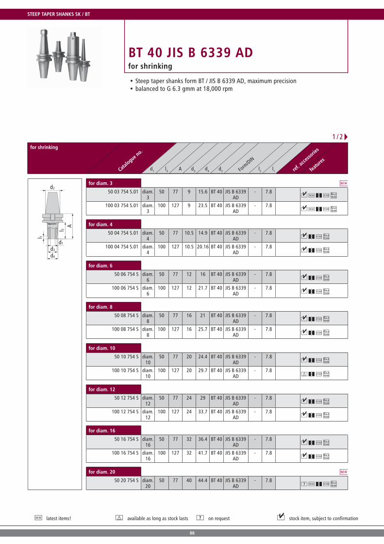
88
latest items! available as long as stock lasts on request stock item, subject to confirmation
BT 40 JIS B 6339 ADfor shrinking
for shrinking
Catalogue n
o.
Form
/DIN
ref. a
ccesso
ries
features
d1 l3 A d3 d4 d2 l2 l1
A
l 1
l 3
d2
d3
d1
d4
for diam. 3
50 03 754 S.01 diam. 3
50 77 9 15.6 BT 40 JIS B 6339 AD
- 7.8
100 03 754 S.01 diam. 3
100 127 9 23.5 BT 40 JIS B 6339 AD
- 7.8
for diam. 4
50 04 754 S.01 diam. 4
50 77 10.5 14.9 BT 40 JIS B 6339 AD
- 7.8
100 04 754 S.01 diam. 4
100 127 10.5 20.16 BT 40 JIS B 6339 AD
- 7.8
for diam. 6
50 06 754 S diam. 6
50 77 12 16 BT 40 JIS B 6339 AD
- 7.8
100 06 754 S diam. 6
100 127 12 21.7 BT 40 JIS B 6339 AD
- 7.8
for diam. 8
50 08 754 S diam. 8
50 77 16 21 BT 40 JIS B 6339 AD
- 7.8
100 08 754 S diam. 8
100 127 16 25.7 BT 40 JIS B 6339 AD
- 7.8
for diam. 10
50 10 754 S diam. 10
50 77 20 24.4 BT 40 JIS B 6339 AD
- 7.8
100 10 754 S diam. 10
100 127 20 29.7 BT 40 JIS B 6339 AD
- 7.8
for diam. 12
50 12 754 S diam. 12
50 77 24 29 BT 40 JIS B 6339 AD
- 7.8
100 12 754 S diam. 12
100 127 24 33.7 BT 40 JIS B 6339 AD
- 7.8
for diam. 16
50 16 754 S diam. 16
50 77 32 36.4 BT 40 JIS B 6339 AD
- 7.8
100 16 754 S diam. 16
100 127 32 41.7 BT 40 JIS B 6339 AD
- 7.8
for diam. 20
50 20 754 S diam. 20
50 77 40 44.4 BT 40 JIS B 6339 AD
- 7.8
Steep taper shanks form BT / JIS B 6339 AD, maximum precisionbalanced to G 6.3 gmm at 18,000 rpm
1 / 2
STEEP TAPER SHANKS SK / BT

89
for shrinking
Catalogue n
o.
Form
/DIN
ref. a
ccesso
ries
features
d1 l3 A d3 d4 d2 l2 l1
A
l 1
l 3
d2
d3
d1
d4
for diam. 25
60 25 754 S diam. 25
60 87 45 45 BT 40 JIS B 6339 AD
- -
2 / 2

90
latest items! available as long as stock lasts on request stock item, subject to confirmation
BT 40 JIS B 6339 ADfor shrinking | zero reach arbors
for shrinking | zero reach arbors
Catalogue n
o.
Form
/DIN
ref. a
ccesso
ries
features
d1 l3 A d3 d4 d2 l2 l1
A
d2
d1
A
d3/d4
l 3
d2
d1
for diam. 16
00 16 754 S diam. 16
0 27 - - BT 40 JIS B 6339 AD
- -
for diam. 20
00 20 754 S diam. 20
0 27 - - BT 40 JIS B 6339 AD
- -
for diam. 25
00 25 754 S diam. 25
10 37 46 46 BT 40 JIS B 6339 AD
- -
Steep taper shanks form BT / JIS B 6339 AD, maximum precisionbalanced to G 6.3 gmm at 18,000 rpm Please note: Zero reach adapters cannot be ordered separately. We only supply in a shrink-grip connection with a solid carbide or dense antivibration adapters. (starting on page 19)
STEEP TAPER SHANKS SK / BT NEW

91
BT 40 JIS B 6339 ADfor shell-type milling
Steep taper shanks form BT / JIS B 6339 AD, maximum precisionbalanced to G 6.3 gmm at 18,000 rpm
for shell-type milling
Catalogue n
o.
Form
/DIN
ref. a
ccesso
ries
features
d1 l3 A d3 d4 d2 l2 l1
Al 3
d1
d3
d4
d2bore diam. 16
25 16 754 Z diam. 16
25 52 38 40 BT 40 JIS B 6339 AD
- 7.8 C, D
50 16 754 Z diam. 16
50 77 38 42 BT 40 JIS B 6339 AD
- 7.8 C, D
75 16 754 Z diam. 16
75 102 38 45 BT 40 JIS B 6339 AD
- 7.8 C, D
100 16 754 Z diam. 16
100 127 38 48 BT 40 JIS B 6339 AD
- 7.8 C, D
150 16 754 Z diam. 16
150 177 38 50 BT 40 JIS B 6339 AD
- 7.8 C, D
bore diam. 22
25 22 754 diam. 22
25 52 40 40 BT 40 JIS B 6339 AD
- 7.8 B, E
50 22 754 diam. 22
50 77 40 40 BT 40 JIS B 6339 AD
- 7.8 B, E
75 22 754 diam. 22
75 102 48 48 BT 40 JIS B 6339 AD
- 7.8 B, E
100 22 754 diam. 22
100 127 48 48 BT 40 JIS B 6339 AD
- 7.8 B, E
150 22 754 diam. 22
150 177 48 48 BT 40 JIS B 6339 AD
- 7.8 B, E
200 22 754 diam. 22
200 227 48 48 BT 40 JIS B 6339 AD
- 7.8 B, E
bore diam. 27
15 27 754 diam. 27
15 42 48 48 BT 40 JIS B 6339 AD
- - A, F
50 27 754 diam. 27
50 77 48 48 BT 40 JIS B 6339 AD
- - A, F
75 27 754 diam. 27
75 102 48 48 BT 40 JIS B 6339 AD
- - A, F
100 27 754 diam. 27
100 127 48 48 BT 40 JIS B 6339 AD
- - A, F
150 27 754 diam. 27
150 177 48 48 BT 40 JIS B 6339 AD
- - A, F
Accessories
M5X12
A > Page 124
M4X10
B > Page 124
M3X10
C > Page 124
NUTEN8X8
D > Page 125
NUTEN10X8 E > Page 125
NUTEN12X8 F > Page 125

92
latest items! available as long as stock lasts on request stock item, subject to confirmation
BT 40 JIS B 6339 ADHSC precision collet chucks
HSC precision collet chucks
Catalogue n
o.
Form
/DIN
ref. a
ccesso
ries
features
d1 l3 A d3 d4 d2 l2 l1
A
d2
l 3l 1
d3
d4
d1
for ER 20
50 ER20 754 ER 20 50 77 28 32 BT 40 JIS B 6339 AD
- 33.8 A, B
100 ER20 754 ER 20 100 127 28 40 BT 40 JIS B 6339 AD
- 33.8 A, B
Accessories
20 501
A > Page 124
ER20 001
B > Page 125
Steep taper shanks form BT / JIS B 6339 AD, maximum precisionbalanced to G 6.3 gmm at 18,000 rpm
STEEP TAPER SHANKS SK / BT

93
BT 40 JIS B 6339 ADfor rotary transmission leadthrough
Steep-angle rotary transmission leadthrough JIS B 6339approved for up to max. 6,000 rpm suitable for oiled compressed air and minimum quantity lubricationindependent of rotating direction
for rotary transmission leadthrough
Catalogue n
o.
Form
/DIN
ref. a
ccesso
ries
features
d1 l3 A d3 d4 d2 l2 l1
A
d3
d4
l 1
d2
l 3
d1
A
l 1l 3
d4
d3
d2
d1
for threaded shank milling
30 12 754 DDLS M 12 30 57 21 25 BT 40 JIS B 6339 AD
- 8
30 16 754 DDLS M 16 30 57 29 30 BT 40 JIS B 6339 AD
- 8
for shell-type milling
30 22 754 DDLS diam. 22
30 57 48 50 BT 40 JIS B 6339 AD
- - A, B
Accessories
KBSK40-69872A
A > Page 125
KBSK40-69872B
B > Page 126
NEW

94
latest items! available as long as stock lasts on request stock item, subject to confirmation
SK 50 DIN 69 871 ADfor screw-on end mills
for screw-on end mills
Catalogue n
o.
Form
/DIN
ref. a
ccesso
ries
features
d1 l3 A d3 d4 d2 l2 l1
d1
l 1
l 3
d2
d3
d4
A
M12
50 12 710 M 12 50 69.1 21 30 SK 50 DIN 69871 AD
- 12 A, B
100 12 710 M 12 100 119.1 21 38 SK 50 DIN 69871 AD
- 12 A, B
150 12 710 M 12 150 169.1 21 52 SK 50 DIN 69871 AD
- 12 A, B
200 12 710 M 12 200 219.1 21 68 SK 50 DIN 69871 AD
- 12 A, B
250 12 710 M 12 250 269.1 21 63 SK 50 DIN 69871 AD
- 12 A, B
300 12 710 M 12 300 319.1 21 68 SK 50 DIN 69871 AD
- 12 A, B
M16
50 16 710 M 16 50 69.1 29 34 SK 50 DIN 69871 AD
- 12 A, B
100 16 710 M 16 100 119.1 29 40 SK 50 DIN 69871 AD
- 12 A, B
150 16 710 M 16 150 169.1 29 48 SK 50 DIN 69871 AD
- 12 A, B
200 16 710 M 16 200 219.1 29 50 SK 50 DIN 69871 AD
- 12 A, B
250 16 710 M 16 250 269.1 29 62 SK 50 DIN 69871 AD
- 12 A, B
300 16 710 M 16 300 319.1 29 68 SK 50 DIN 69871 AD
- 12 A, B
Accessories
KBSK50-69872A
A > Page 125
KBSK50-69872B
B > Page 126
Steep taper shanks DIN 69871 AD, maximum precisionbalanced to G 16 gmm at 8,000 rpm
STEEP TAPER SHANKS SK / BT

95
SK 50 DIN 69 871 ADfor shrinking
Steep taper shanks DIN 69871 AD, maximum precisionbalanced to G 16 gmm at 8,000 rpm
for shrinking
Catalogue n
o.
Form
/DIN
ref. a
ccesso
ries
features
d1 l3 A d3 d4 d2 l2 l1
l 1
d1
d3
l 3A
d2
d4
for diam. 6
50 06 710 S diam. 6
50 69.1 12 17 SK 50 DIN 69871 AD
- 7.8 A, B
100 06 710 S diam. 6
100 119.1 12 21.7 SK 50 DIN 69871 AD
- 7.8 A, B
150 06 710 S diam. 6
150 169.1 12 27 SK 50 DIN 69871 AD
- 7.8 A, B
200 06 710 S diam. 6
200 219.1 12 32 SK 50 DIN 69871 AD
- 7.8 A, B
for diam. 8
50 08 710 S diam. 8
50 69.1 16 21 SK 50 DIN 69871 AD
- 7.8 A, B
100 08 710 S diam. 8
100 119.1 16 26 SK 50 DIN 69871 AD
- 7.8 A, B
150 08 710 S diam. 8
150 169.1 16 30.9 SK 50 DIN 69871 AD
- 7.8 A, B
200 08 710 S diam. 8
200 219.1 16 36 SK 50 DIN 69871 AD
- 7.8 A, B
for diam. 10
50 10 710 S diam. 10
50 69.1 20 25 SK 50 DIN 69871 AD
- 7.8 A, B
100 10 710 S diam. 10
100 119.1 20 30 SK 50 DIN 69871 AD
- 7.8 A, B
150 10 710 S diam. 10
150 169.1 20 35 SK 50 DIN 69871 AD
- 7.8 A, B
200 10 710 S diam. 10
200 219.1 20 40 SK 50 DIN 69871 AD
- 7.8 A, B
for diam. 12
50 12 710 S diam. 12
50 69.1 24 28.4 SK 50 DIN 69871 AD
- 7.8 A, B
100 12 710 S diam. 12
100 119.1 24 33.7 SK 50 DIN 69871 AD
- 7.8 A, B
150 12 710 S diam. 12
150 169.1 24 39 SK 50 DIN 69871 AD
- 7.8 A, B
Accessories
KBSK50-69872A
A > Page 125
KBSK50-69872B
B > Page 126
1 / 2

96
latest items! available as long as stock lasts on request stock item, subject to confirmation
for shrinking
Catalogue n
o.
Form
/DIN
ref. a
ccesso
ries
features
d1 l3 A d3 d4 d2 l2 l1
l 1
d1
d3
l 3A
d2
d4
for diam. 16
50 16 710 S diam. 16
50 69.1 32 36.4 SK 50 DIN 69871 AD
- 7.8 A, B
100 16 710 S diam. 16
100 119.1 32 41.7 SK 50 DIN 69871 AD
- 7.8 A, B
150 16 710 S diam. 16
150 169.1 32 46.9 SK 50 DIN 69871 AD
- 7.8 A, B
200 16 710 S diam. 16
200 219.1 32 52 SK 50 DIN 69871 AD
- 7.8 A, B
for diam. 20
50 20 710 S diam. 20
50 69.1 40 44.4 SK 50 DIN 69871 AD
- 7.8 A, B
100 20 710 S diam. 20
100 119.1 40 50 SK 50 DIN 69871 AD
- 7.8 A, B
for diam. 25
60 25 710 S diam. 25
60 79.1 46 46 SK 50 DIN 69871 AD
- - A, B
100 25 710 S diam. 25
100 119.1 46 56 SK 50 DIN 69871 AD
- 7.8 A, B
Zubehör
KBSK50-69872A
A > Page 125
KBSK50-69872B
B > Page 126
Steep taper shanks DIN 69871 AD, maximum precisionbalanced to G 16 gmm at 8,000 rpm
SK 50 DIN 69 871 ADfor shrinking
2 / 2
STEEP TAPER SHANKS SK / BT

97
SK 50 DIN 69 871 ADfor shrinking | zero reach arbors
Steep taper shanks DIN 69871 AD, maximum precisionbalanced to G 16 gmm at 8,000 rpm Please note: Zero reach adapters cannot be ordered separately. We only supply in a shrink-grip connection with a solid carbide or dense antivibration adapters. (starting on page 19)
for shrinking | zero reach arbors
Catalogue n
o.
Form
/DIN
ref. a
ccesso
ries
features
d1 l3 A d3 d4 d2 l2 l1
A
d2
d1
A
d1
d3/d4
d2
for diam. 20
00 20 710 S diam. 20
0 19.1 - - SK 50 DIN 69871 AD
- - A, B
for diam. 25
00 25 710 S diam. 25
0 19.1 - - SK 50 DIN 69871 AD
- - A, B
for diam. 36
00 36 710 S diam. 36
10 29.1 50 50 SK 50 DIN 69871 AD
- - A, B
Accessories
KBSK50-69872A
A > Page 125
KBSK50-69872B
B > Page 126

98
latest items! available as long as stock lasts on request stock item, subject to confirmation
SK 50 DIN 69 871 ADfor shell-type milling
for shell-type milling
Catalogue n
o.
Form
/DIN
ref. a
ccesso
ries
features
d1 l3 A d3 d4 d2 l2 l1
A
d1
d4
d3
l 1 l 3
d1
bore diam. 16
50 16 710 Z diam. 16
50 69.1 38 42 SK 50 DIN 69871 AD
- 7.8 B, D, H, I
100 16 710 Z diam. 16
100 119.1 38 50 SK 50 DIN 69871 AD
- 7.8 B, D, H, I
150 16 710 Z diam. 16
150 169.1 38 50 SK 50 DIN 69871 AD
- 7.8 B, D, H, I
200 16 710 Z diam. 16
200 219.1 38 50 SK 50 DIN 69871 AD
- 7.8 B, D, H, I
250 16 710 Z diam. 16
250 269.1 38 50 SK 50 DIN 69871 AD
- 7.8 B, D, H, I
300 16 710 Z diam. 16
300 319.1 38 50 SK 50 DIN 69871 AD
- 7.8 B, D, H, I
bore diam. 22
50 22 710 diam. 22
50 69.1 40 40 SK 50 DIN 69871 AD
- - A, E, H, I
100 22 710.01 diam. 22
100 119.1 48 50 SK 50 DIN 69871 AD
- 7.8 A, E, H, I
150 22 710 diam. 22
150 169.1 48 62 SK 50 DIN 69871 AD
- 7.8 A, E, H, I
200 22 710 diam. 22
200 219.1 48 78 SK 50 DIN 69871 AD
- 7.8 A, E, H, I
bore diam. 27
50 27 710 diam. 27
50 69.1 62 62 SK 50 DIN 69871 AD
- - C, F, H, I
100 27 710 diam. 27
100 119.1 62 70 SK 50 DIN 69871 AD
- 7.8 C, F, H, I
150 27 710 diam. 27
150 169.1 62 76 SK 50 DIN 69871 AD
- 7.8 C, F, H, I
200 27 710 diam. 27
200 219.1 62 76 SK 50 DIN 69871 AD
- 7.8 C, F, H, I
250 27 710 diam. 27
250 269.1 62 76 SK 50 DIN 69871 AD
- 7.8 C, F, H, I
Steep taper shanks DIN 69871 AD, maximum precisionbalanced to G 16 gmm at 8,000 rpm
1 / 2
STEEP TAPER SHANKS SK / BT

99
for shell-type milling
Catalogue n
o.
Form
/DIN
ref. a
ccesso
ries
features
d1 l3 A d3 d4 d2 l2 l1
Ad1
d4
d3
l 1 l 3
d1
bore diam. 32
50 32 710 diam. 32
50 69.1 95 78 SK 50 DIN 69871 AD
- 7.8 C, G, H, I
100 32 710 diam. 32
100 119.1 95 78 SK 50 DIN 69871 AD
- 7.8 C, G, H, I
150 32 710 diam. 32
150 169.1 95 78 SK 50 DIN 69871 AD
- 7.8 C, G, H, I
200 32 710 diam. 32
200 219.1 95 78 SK 50 DIN 69871 AD
- 7.8 C, G, H, I
Accessories
M4X10
A > Page 124
M3X10
B > Page 124
M5X16
C > Page 124
NUTEN8X8
D > Page 125
NUTEN10X8 E > Page 125
NUTEN12X12/2 F > Page 125
NUTEN14X14 G > Page 125
KBSK50-69872A
H > Page 125
KBSK50-69872B
I > Page 126
2 / 2
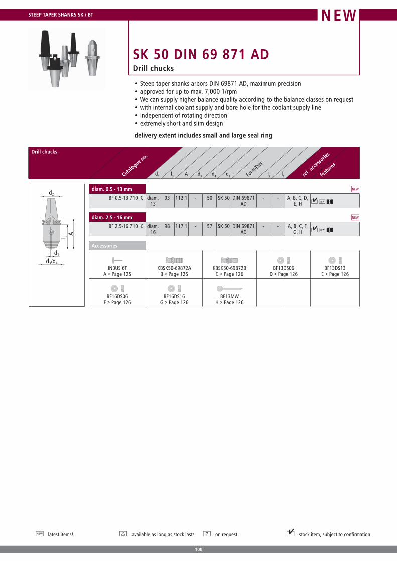
100
latest items! available as long as stock lasts on request stock item, subject to confirmation
SK 50 DIN 69 871 ADDrill chucks
Drill chucks
Catalogue n
o.
Form
/DIN
ref. a
ccesso
ries
features
d1 l3 A d3 d4 d2 l2 l1
Al 3
d3/d4
d2
d1
diam. 0.5 - 13 mm
BF 0,5-13 710 IC diam. 13
93 112.1 - 50 SK 50 DIN 69871 AD
- - A, B, C, D, E, H
diam. 2.5 - 16 mm
BF 2,5-16 710 IC diam. 16
98 117.1 - 57 SK 50 DIN 69871 AD
- - A, B, C, F, G, H
Accessories
INBUS 6T
A > Page 125
KBSK50-69872A
B > Page 125
KBSK50-69872B
C > Page 126
BF13DS06
D > Page 126
BF13DS13
E > Page 126
BF16DS06
F > Page 126
BF16DS16
G > Page 126
BF13MW
H > Page 126
Steep taper shanks arbors DIN 69871 AD, maximum precisionapproved for up to max. 7,000 1/rpmWe can supply higher balance quality according to the balance classes on requestwith internal coolant supply and bore hole for the coolant supply lineindependent of rotating directionextremely short and slim design
delivery extent includes small and large seal ring
STEEP TAPER SHANKS SK / BT NEW

101
SK 50 DIN 69 871 ADfor morse taper shanks
Steep taper shanks DIN 69871 AD, maximum precisionbalanced to G 16 gmm at 8,000 rpm
for morse taper shanks
Catalogue n
o.
Form
/DIN
ref. a
ccesso
ries
features
d1 l3 A d3 d4 d2 l2 l1
A
d3
d2
l 3
d4
d1
MTS 2
40 2 710 MTS 2
50 69.1 30 36 SK 50 DIN 69871 AD
- - A, J, K, N, O, P
90 2 710 MTS 2
90 109.1 30 46 SK 50 DIN 69871 AD
- - B, J, K, N, O, P
140 2 710 MTS 2
140 159.1 30 56 SK 50 DIN 69871 AD
- - C, J, K, N, O, P
MTS 3
50 3 710 MTS 3
50 69.1 38 46 SK 50 DIN 69871 AD
- - D, J, K, N, O, P
100 3 710 MTS 3
100 119.1 38 56 SK 50 DIN 69871 AD
- - E, J, K, N, O, P
150 3 710 MTS 3
150 169.1 38 62 SK 50 DIN 69871 AD
- - F, J, K, N, O, P
200 3 710 MTS 3
200 219.1 38 70 SK 50 DIN 69871 AD
- - G, J, K, N, O, P
MTS 4
80 4 710 MTS 4
80 99.1 44 56 SK 50 DIN 69871 AD
- - H, J, L, N, O, Q
130 4 710 MTS 4
130 149.1 44 70 SK 50 DIN 69871 AD
- - H, J, L, N, O, Q
180 4 710 MTS 4
180 199.1 44 70 SK 50 DIN 69871 AD
- - H, J, L, N, O, Q
250 4 710 MTS 4
250 269.1 44 70 SK 50 DIN 69871 AD
- - H, J, L, N, O, Q
Accessories
M10X40
A > Page 124
M10X90
B > Page 124
M10X140
C > Page 124
M12X40
D > Page 124
M12X90
E > Page 124
M12X135
F > Page 124
M12X185
G > Page 124
M16X50
H > Page 124
M20X50
I > Page 124
GWST-M5X8-914
J > Page 124
1003
K > Page 124
1004
L > Page 124
1005
M > Page 124
KBSK50-69872A
N > Page 125
KBSK50-69872B O > Page 126
ZGHM2414
P > Page 126
ZGHM2414L Q > Page 126
ZGHM3316L R > Page 126
1 / 2

102
latest items! available as long as stock lasts on request stock item, subject to confirmation
for morse taper shanks
Catalogue n
o.
Form
/DIN
ref. a
ccesso
ries
features
d1 l3 A d3 d4 d2 l2 l1
A
d3
d2
l 3
d4
d1
MTS 5
100 5 710 MTS 5
100 119.1 56 70 SK 50 DIN 69871 AD
- - I, J, M, N, O, R
150 5 710 MTS 5
150 169.1 56 70 SK 50 DIN 69871 AD
- - I, J, M, N, O, R
200 5 710 MTS 5
200 219.1 56 75 SK 50 DIN 69871 AD
- - I, J, M, N, O, R
Accessories
M10X40
A > Page 124
M10X90
B > Page 124
M10X140
C > Page 124
M12X40
D > Page 124
M12X90
E > Page 124
M12X135
F > Page 124
M12X185
G > Page 124
M16X50
H > Page 124
M20X50
I > Page 124
GWST-M5X8-914
J > Page 124
1003
K > Page 124
1004
L > Page 124
1005
M > Page 124
KBSK50-69872A
N > Page 125
KBSK50-69872B O > Page 126
ZGHM2414
P > Page 126
ZGHM2414L Q > Page 126
ZGHM3316L R > Page 126
Steep taper shanks DIN 69871 AD, maximum precisionbalanced to G 16 gmm at 8,000 rpm
SK 50 DIN 69 871 ADfor morse taper shanks
2 / 2
STEEP TAPER SHANKS SK / BT

103
SK 50 DIN 69 871 ADfor rotary transmission leadthrough
steep-angle rotary transmission leadthrough DIN 69871 ADapproved for up to max. 6,000 rpmsuitable for oiled compressed air and minimum quantity lubricationindependent of rotating direction
for rotary transmission leadthrough
Catalogue n
o.
Form
/DIN
ref. a
ccesso
ries
features
d1 l3 A d3 d4 d2 l2 l1
A
d3
d4
l 1
d2
l 3
d1
for shell-type milling
50 27 710 DDLS diam. 27
50 69.1 62 65 SK 50 DIN 69871 AD
- - A, B
Accessories
KBSK50-69872A
A > Page 125
KBSK50-69872B
B > Page 126
NEW

104
latest items! available as long as stock lasts on request stock item, subject to confirmation
BT 50 JIS B 6339 ADfor screw-on end mills
for screw-on end mills
Catalogue n
o.
Form
/DIN
ref. a
ccesso
ries
features
d1 l3 A d3 d4 d2 l2 l1
A
d1
d3
d2
l 1
l 3
d4
M12
50 12 714 M 12 50 88 21 30 BT 50 JIS B 6339 AD
- 12
100 12 714 M 12 100 138 21 38 BT 50 JIS B 6339 AD
- 12
150 12 714 M 12 150 188 21 52 BT 50 JIS B 6339 AD
- 12
200 12 714 M 12 200 238 21 58 BT 50 JIS B 6339 AD
- 12
250 12 714 M 12 250 288 21 63 BT 50 JIS B 6339 AD
- 12
300 12 714 M 12 300 338 21 68 BT 50 JIS B 6339 AD
- 12
M16
50 16 714 M 16 50 88 29 34 BT 50 JIS B 6339 AD
- 12
100 16 714 M 16 100 138 29 40 BT 50 JIS B 6339 AD
- 12
150 16 714 M 16 150 188 29 48 BT 50 JIS B 6339 AD
- 12
200 16 714 M 16 200 238 29 58 BT 50 JIS B 6339 AD
- 12
250 16 714 M 16 250 288 29 62 BT 50 JIS B 6339 AD
- 12
300 16 714 M 16 300 338 29 68 BT 50 JIS B 6339 AD
- 12
Steep taper shanks form BT / JIS B 6339 AD, maximum precisionbalanced to G 16 gmm at 8,000 rpm
STEEP TAPER SHANKS SK / BT

105
BT 50 JIS B 6339 ADfor shrinking
Steep taper shanks form BT / JIS B 6339 AD, maximum precisionbalanced to G 16 gmm at 8,000 rpm
for shrinking
Catalogue n
o.
Form
/DIN
ref. a
ccesso
ries
features
d1 l3 A d3 d4 d2 l2 l1
A
l 1
l 3
d2
d3
d1
d4
for diam. 6
50 06 714 S diam. 6
50 88 12 17 BT 50 JIS B 6339 AD
- 7.8
100 06 714 S diam. 6
100 138 12 21.7 BT 50 JIS B 6339 AD
- 7.8
150 06 714 S diam. 6
150 188 12 27 BT 50 JIS B 6339 AD
- 7.8
200 06 714 S diam. 6
200 238 12 32 BT 50 JIS B 6339 AD
- 7.8
for diam. 8
50 08 714 S diam. 8
50 88 16 21 BT 50 JIS B 6339 AD
- 7.8
100 08 714 S diam. 8
100 138 16 26 BT 50 JIS B 6339 AD
- 7.8
150 08 714 S diam. 8
150 188 16 30.9 BT 50 JIS B 6339 AD
- 7.8
200 08 714 S diam. 8
200 238 16 36 BT 50 JIS B 6339 AD
- 7.8
for diam. 10
50 10 714 S diam. 10
50 88 20 25 BT 50 JIS B 6339 AD
- 7.8
100 10 714 S diam. 10
100 138 20 30 BT 50 JIS B 6339 AD
- 7.8
150 10 714 S diam. 10
150 188 20 35 BT 50 JIS B 6339 AD
- 7.8
200 10 714 S diam. 10
200 238 20 40 BT 50 JIS B 6339 AD
- 7.8
for diam. 12
50 12 714 S diam. 12
50 88 24 28.4 BT 50 JIS B 6339 AD
- 7.8
100 12 714 S diam. 12
100 138 24 33.7 BT 50 JIS B 6339 AD
- 7.8
150 12 714 S diam. 12
150 188 24 39 BT 50 JIS B 6339 AD
- 7.8
for diam. 16
50 16 714 S diam. 16
50 88 32 36.4 BT 50 JIS B 6339 AD
- 7.8
100 16 714 S diam. 16
100 138 32 41.7 BT 50 JIS B 6339 AD
- 7.8
150 16 714 S diam. 16
150 188 32 46.9 BT 50 JIS B 6339 AD
- 7.8
200 16 714 S diam. 16
200 238 32 52 BT 50 JIS B 6339 AD
- 7.8
1 / 2

106
latest items! available as long as stock lasts on request stock item, subject to confirmation
for shrinking
Catalogue n
o.
Form
/DIN
ref. a
ccesso
ries
features
d1 l3 A d3 d4 d2 l2 l1
A
l 1
l 3
d2
d3
d1
d4
for diam. 20
50 20 714 S diam. 20
50 88 40 44.4 BT 50 JIS B 6339 AD
- 7.8
100 20 714 S diam. 20
100 138 40 50 BT 50 JIS B 6339 AD
- 7.8
for diam. 25
60 25 714 S diam. 25
60 98 46 46 BT 50 JIS B 6339 AD
- -
100 25 714 S diam. 25
100 138 46 56 BT 50 JIS B 6339 AD
- 7.8
for diam. 36
60 36 714 S diam. 25
60 98 72 72 BT 50 JIS B 6339 AD
- -
Steep taper shanks form BT / JIS B 6339 AD, maximum precisionbalanced to G 16 gmm at 8,000 rpm
BT 50 JIS B 6339 ADfor shrinking
2 / 2
STEEP TAPER SHANKS SK / BT

107
BT 50 JIS B 6339 ADfor shrinking | zero reach arbors
Steep taper shanks form BT / JIS B 6339 AD, maximum precisionbalanced to G 16 gmm at 8,000 rpm Please note: Zero reach arbors cannot be ordered separately. We only supply in a shrink-grip connection with a solid carbide or dense antivibration adap-ters. (starting on page 19)
for shrinking | zero reach arbors
Catalogue n
o.
Form
/DIN
ref. a
ccesso
ries
features
d1 l3 A d3 d4 d2 l2 l1
A
d2
d1
A
d3/d4
l 3
d2
d1
for diam. 20
00 20 714 S diam. 20
0 38 - - BT 50 JIS B 6339 AD
- -
for diam. 25
00 25 714 S diam. 25
0 38 - - BT 50 JIS B 6339 AD
- -
for diam. 36
10 36 714 S diam. 36
10 48 50 50 BT 50 JIS B 6339 AD
- -
NEW

108
latest items! available as long as stock lasts on request stock item, subject to confirmation
BT 50 JIS B 6339 ADfor shell-type milling
for shell-type milling
Catalogue n
o.
Form
/DIN
ref. a
ccesso
ries
features
d1 l3 A d3 d4 d2 l2 l1
Al 3
d1
d3
d4
d2bore diam. 16
50 16 714 Z diam. 16
50 88 38 42 BT 50 JIS B 6339 AD
- 7.8 C, E
100 16 714 Z diam. 16
100 138 38 50 BT 50 JIS B 6339 AD
- 7.8 C, E
150 16 714 Z diam. 16
150 188 38 50 BT 50 JIS B 6339 AD
- 7.8 C, E
bore diam. 22
50 22 714 diam. 22
50 88 40 40 BT 50 JIS B 6339 AD
- 7.8 B, F
100 22 714 diam. 22
100 138 48 50 BT 50 JIS B 6339 AD
- 7.8 B, F
150 22 714 diam. 22
150 188 48 62 BT 50 JIS B 6339 AD
- 7.8 B, F
200 22 714 diam. 22
200 238 48 78 BT 50 JIS B 6339 AD
- 7.8 B, F
bore diam. 27
50 27 714 diam. 27
50 88 62 62 BT 50 JIS B 6339 AD
- 7.8 A, G
100 27 714 diam. 27
100 138 62 70 BT 50 JIS B 6339 AD
- 7.8 A, G
150 27 714 diam. 27
150 188 62 76 BT 50 JIS B 6339 AD
- 7.8 A, G
200 27 714 diam. 22
200 238 62 76 BT 50 JIS B 6339 AD
- 7.8 A, G
bore diam. 32
50 32 714 diam. 32
50 88 95 78 BT 50 JIS B 6339 AD
- 7.8 D, H
100 32 714 diam. 32
100 138 95 78 BT 50 JIS B 6339 AD
- 7.8 D, H
150 32 714 diam. 32
150 188 95 78 BT 50 JIS B 6339 AD
- 7.8 D, H
200 32 714 diam. 32
200 238 95 78 BT 50 JIS B 6339 AD
- 7.8 D, H
Accessories
M5X12
A > Page 124
M4X10
B > Page 124
M3X10
C > Page 124
M5X16
D > Page 124
NUTEN8X8
E > Page 125
NUTEN10X8 F > Page 125
NUTEN12X12/2 G > Page 125
NUTEN14X14 H > Page 125
Steep taper shanks form BT / JIS B 6339 AD, maximum precisionbalanced to G 16 gmm at 8,000 rpm
STEEP TAPER SHANKS SK / BT

109
BT 50 JIS B 6339 ADfor rotary transmission leadthrough
steep-angle rotary transmission leadthrough JIS B 6339approved for up to max. 6,000 rpmsuitable for oiled compressed air and minimum quantity lubricationindependent of rotating direction
for rotary transmission leadthrough
Catalogue n
o.
Form
/DIN
ref. a
ccesso
ries
features
d1 l3 A d3 d4 d2 l2 l1
A
l 1l 3
d4
d3
d2
d1
for shell-type milling
50 27 714 DDLS diam. 27
50 88 62 65 BT 50 JIS B 6339 AD
- -
NEW

110110

Page
SK 50 for shell type milling 112
centering arbor / adapter 114
DIRECT SPINDLE MOIUNTINGDIRECT SPINDLE MOUNTING
111

112
latest items! available as long as stock lasts on request stock item, subject to confirmation
SK 50for shell-type milling
for shell-type milling
Catalogue n
o.
Form
/DIN
ref. a
ccesso
ries
features
d1 l3 A d3 d4 d2 l2 l1
A
l 1
d3
d1
d4
l 3
d2
Ø 17
45°
Ø 101,6
bore diam. 22
200 22 740 diam. 22
200 233 48 78 diam. 50
direct spindle mounting
- 38 B, D, H
250 22 740 diam. 22
250 283 48 82 diam. 50
direct spindle mounting
- 38 B, D, H
300 22 740 diam. 22
300 333 48 86 diam. 50
direct spindle mounting
- 38 B, D, H
350 22 740 diam. 22
350 383 48 90 diam. 50
direct spindle mounting
- 38 B, D, H
400 22 740 diam. 22
400 433 48 95 diam. 50
direct spindle mounting
- 38 B, D, H
bore diam. 27
200 27 740 diam. 27
200 233 62 78 diam. 50
direct spindle mounting
- 38 C, E, H
250 27 740 diam. 27
250 283 62 82 diam. 50
direct spindle mounting
- 38 C, E, H
300 27 740 diam. 27
300 333 62 86 diam. 50
direct spindle mounting
- 38 C, E, H
350 27 740 diam. 27
350 383 62 90 diam. 50
direct spindle mounting
- 38 C, E, H
400 27 740 diam. 27
400 433 62 95 diam. 50
direct spindle mounting
- 38 C, E, H
bore diam. -Ø 32
100 32 740 diam. 32
100 133 85 98 diam. 50
direct spindle mounting
- 38 C, F, H
150 32 740 diam. 32
150 183 85 98 diam. 50
direct spindle mounting
- 38 C, F, H
200 32 740 diam. 32
200 233 85 98 diam. 50
direct spindle mounting
- 38 C, F, H
250 32 740 diam. 32
250 283 90 105 diam. 50
direct spindle mounting
- 38 C, F, H
300 32 740 diam. 32
300 333 90 110 diam. 50
direct spindle mounting
- 38 C, F, H
350 32 740 diam. 32
350 383 90 117 diam. 50
direct spindle mounting
- 38 C, F, H
400 32 740 diam. 32
400 433 90 124 diam. 50
direct spindle mounting
- 38 C, F, H
flange contact surfaces for direct mounting on the machine spindleanchor points made according to DIN 1830 for attaching to milling spindle heads according to DIN 2079highest degree of stability and rigidity with long projections or difficult machining tasks
1 / 2
DIRECT SPINDLE MOUNTING

113
for shell-type milling
Catalogue n
o.
Form
/DIN
ref. a
ccesso
ries
features
d1 l3 A d3 d4 d2 l2 l1
A
l 1
d3
d1
d4
l 3
d2
Ø 17
45°
Ø 101,6
bore diam. 40
100 40 740 diam. 40
100 133 100 124 diam. 50
direct spindle mounting
- 38 A, G, H
150 40 740 diam. 40
150 183 100 124 diam. 50
direct spindle mounting
- 38 A, G, H
200 40 740 diam. 40
200 233 100 124 diam. 50
direct spindle mounting
- 38 A, G, H
Accessories
M6X16
A > Page 124
M4X10
B > Page 124
M5X16
C > Page 124
NUTEN10X8
D > Page 125
NUTEN12X12/2 E > Page 125
NUTEN14X14 F > Page 125
NUTEN16X16 G > Page 125
Z 00038
H > Page 126
2 / 2

114
latest items! available as long as stock lasts on request stock item, subject to confirmation
SK 50centering arbor/ adapter
centering arbor/ adapter
Catalogue n
o.
Form
/DIN
ref. a
ccesso
ries
features
d1 l3 A d3 d4 d2 l2 l1
SK 50 DIN 2080
50 742 diam. 50
- - - - SK 50 DIN 2080 - -
SK 50 DIN 69 871 AD
50 743 diam. 50
- - - - SK 50 DIN 69871 AD
- - E, F
HSK 100 form A
40 740 A100 diam. 50
14.5 43.5 126 126 HSK 100
form A - - A, B, C, D
Accessories
M12X35
A > Page 124
GWST-M6X10-914
B > Page 124
KMR-100A
C > Page 125
SCHLUESSELHSK100
D > Page 125
KBSK50-69872A
E > Page 125
KBSK50-69872B
F > Page 126
flange contact surfaces for direct mounting on the machine spindleanchor points made according to DIN 1830 for attaching to milling spindle heads according to DIN 2079highest degree of stability and rigidity with long projections or difficult machining tasks
l 3
d3/d4
d1
d2
d1
d1
114
DIRECT SPINDLE MOUNTING

115

kW Nm
60000 U/min
1,40,23
0
0,3
0,6
0,9
1,2
1,5
0 5000 10000 15000 20000 30000 40000 50000 60000 70000 80000Drehzahl/RPM
kW
0
0,1
0,2
0,3
Dauerleistung
000000000000 UUUU////mmmiiiiinnnnnnnnn
00000000
0000,0,0,0,0,0,,,,,33333333333333
0,0,0,0,,666666
0,9
1,2
1,5
000 5050505000000000 10101010000000000000000000000000000000000000000000000 15151515155155151515151515151155150000000000000000000000 0 200
kW
Daueeeeeeeeeeeeerrrrrrrrrrrrrrrrrllllllleeeeeeeeeeeeeeeeeeiiiiiiiiiiiiiiissssssssssssssssssttttttttttttttttttuuuuuuuuuuuuuuuuuunnnnnnnnnnnnnnnnnngggggggggggggggggg
HIGH-SPEED SPINDLE SYSTEMS
MODERN SPINDLE UNITS FOREFFECTIVE MILLINGS RESULTS
Many milling machines – both old and new – have a relatively low maximum speed. Low maximum speed does have advanta-ges in roughing operations, but are a big drawback for achie-ving effective feed rates.Low speed also greatly limits the ad-vantages of modern CNC applications. The results: much longer machining times and loss of valuable production capacities.
We offer a convincing solution for this situation:Pokolm high-speed spindle systems for the most profitable machining re-sults.
u spare parts u repairs u inspection u maintenance
u swivel devices u CNC machine
connection
Ask our service centre about spindles:
Please contact us!
BETTER SURFACE FINISH RESULTS AND GREATLY IM-PROVED CYCLE TIME
The advantages are impressive: higher cutting speeds, uti-lization of maximum feed rates – even with the smallest end mills – better surface finish and a great reduction in the need for EDM. Results: much shorter machining times and full utilization of the CNC advantages.
Pokolm-Voha provides various spindle systems for indivi-dual adaptation to existing machines and operation re-quirements. When you mill with an action angle of the A + C axes, you increase the variety of applications of your milling machine with our swivel device.
Get the maximum speed from your machines with Pokolm spindle systems. The result: You save time!
TOOLING SYSTEMS PROCESS OPTIMIZATION CONSULTING IN MILLNG STRATEGIES
BETTER SURFACE FINISH RESULTS AND GREATLY IM-PROVED CYCLE TIME
The advantages are impressive: higher cutting speeds, uti-lization of maximum feed rates – even with the smallest end mills – better surface finish and a great reduction in the need for EDM. Results: much shorter machining times and full utilization of the CNC advantages.
Pokolm-Voha provides various spindle systems for indivi-dual adaptation to existing machines and operation re-quirements. When you mill with an action angle of the A + C axes, you increase the variety of applications of your milling machine with our swivel device.
Get the maximum speed from your machines with Pokolm spindle systems. The result: You save time!
High-Speed Spindle Systems
HIGH-SPEED SPINDLE SYSTEMS
116

FIRST OPERATION: SHRINKING, THEN MILLING
Shrinking Technology convinces everybody compared with conventional chucking methods from the past. What counts? Absolute concentricity and highest precision with extensive extended tool life. Shrinking technology offers a safe friction-locked connection between tool and tool holder and povides an increased transferable torque. And the qualification for maximum revolutions is the best pre-condition for an optimum surface finish and for reducing costs for expensive finishing processes.
Compared to coventional milling chucks, shrinking arbors allow the use of distinctly slim adaptors for machining components with narrow situations, which would be unexecutable with other tool-holding sys-tems.
Pokolm offers a substantial range of tooling for shrinking technology: several top-class Induction Shrinking Units, shrinking arbors for all possible machine connections and our patent-protected connection system DuoPlug® in combination with our „zero-reach“-shrinking arbors.(Additional information about the Pokolm DuoPlug® Sys-tem can be found in the catalogue about „Milling Cutter Bodies“.)
INDUCTIVE SHRINKING TECHNOLOGY
SHRINKING TECHNOLOGY
TOOLING SYSTEMS PROCESS OPTIMIZATION CONSULTING IN MILLNG STRATEGIES
117

PURCHASE / INQUIRY FORMCustomized Arbors
Inquiry No./P.O. No.: Date:
Company:
Address:
Department:
Field service
Person in charge:
indoor service
Phone: Fax: Email:
Please fax to:
POKOLM: +49 5247 9361-99u(please copy prior to completion)
Arbor for threaded shank end mill bodies
Arbor for Shell-type Milling Cutter Bodies
Shrinking Arbor
Qty.
Qty.
Qty.
HRC
HRC
HRC
balance grade required
balance grade required
balance grade requiredManufactured from material
Manufactured from material
Manufactured from material
Requested delivery date
angle
angle
angle
d4
d4
d4
d3
d3
d3
d1
d1
d1
l1
l1
r
r
l3
l3
SK/BT
Surface treatment
(size)
(size)
(size)
Nickel
Nickel
(DIN/JIS)
browned
browned
HSK
HSK
HSK
Internal Coolant Supply
(size)
(size)
(size)
(form)
(form)
(form)
central bore
central bore
central bore
through the collar
through the collar
through the collar
Internal Coolant Supply
Internal Coolant Supply
Note: For cylindrical design please fill in d3 and d4. 4 calendar weeks delivery time with browned surface.
l1 r
l3
browned
SK/BT
SK/BT
(DIN/JIS)
(DIN/JIS)
118
PURCHASE / INQUIRY FORM

PURCHASE / INQUIRY FORMCustomized Adapters
Inquiry No./P.O. No.: Date:
Company:
Address:
Department:
Indoor service
Person in charge:
Field service
Phone: Fax: Email:
Please fax to:
POKOLM: +49 5247 9361-99u(please copy prior to completion)
Dense Antivibration Material Adapters for Threaded Shank End Mill Bodies
Solid Carbide Adapters for DuoPlug® System
Morse Taper Adapters for Threaded Shank End Mill Bodies
Requested delivery date
Requested delivery date
Requested delivery date
with clamping flats
Internal Coolant Supply
Internal Coolant Supply
Qty.
Qty.
l1
l1
l3
l3
d4
d4
d4
d1
d1
d3
d3
d2
d2
Internal Coolant SupplyQty.Material:
HRC
l1
l3
d1d3
Surface treatment
Nickel
MTS size
browned
Note: For cylindrical design please fill in d3 and d4. 4 Calendar weeks delivery time with browned surface.
119

PURCHASE
Please fax to:
POKOLM: +49 5247 9361-99u(please copy prior to completion)
You can of course also place your order with one of our applications engineers.
Your purchase order by fax
Address:
Company:
Catalogue no. Description of item Quantity Price per item
Total
Total price
Department:
name
Our terms of sale are valid for this faxed purchase order.
Different delivery address
Company:
street
zip code, city
customer number (if known)
street
zip code, city
120
PURCHASE ORDER

NOTES
121
that's a must!High-quality original accessories.
In case, you decide to purchase high quality Pokolm too-ling, you should also set the same high standards, when purchasing accessories - just to be on the safe side.
Pokolm is using quality screws, screwdrivers and other accessories made by leading manufacturers. It is always optimally coordinated with the high-performance capabi-lities of our own products.
ACCESSORIES
122
ACCESSORIES

Page
Cylindrical screws with hexagon socket for drive blocks 124
for MTS-reduction sleeves 124
Additional screws and washers Setscrew 124
Spanners / screwdrivers Spanner for tightning nut of ER20-collet chucks 124
Spanners for reduction sleeves 124
Spanners for drill chucks 125
Union nuts 125
Drive blocks 125
Accessories for HSK tooling Coolant supply tube for HSK tooling 125
Spanners for coolant supply tube 125
Retention knobs without seal ring groove 125
Retention knobs with seal ring groove 126
Threaded bushes 126
Drill chuck accessoires Seal gasket 126
Hexagon key 126
Tightening bold Tightening bold 126
ACCESSORIESACCESSORIES
123

Accessories
Catalogue n
o.
Dimen
sions
Description
Cylindrical screws with hexagon socket | for drive blocks
M6X16 screw for drive block 16 x 16 M 6 | L 16 | DIN 912 M 6 L 16 DIN 912
M5X12 screw for drive block 12 x 8 M 5 | L 12 | DIN 912 M 5 L 12 DIN 912
M4X10 screw for drive block 10 x 8 M 4 | L 10 | DIN 912 M 4 L 10 DIN 912
M3X10 screws for drive block 8 x 8 M 3 | L 10 | DIN 912 M 3 L 10 DIN 912
M5X16 screw for drive blocks 12 x 12 and 14 x 14 M 5 | L 16 | DIN 912
M 5 L 16 DIN 912
M12X35 screw M 12 | L 20 | DIN 912 M 12 L 20 DIN 912
Cylindrical screws with hexagon socket | for MTS-reduction sleeves
M10X40 screws for MTS-reduction sleeve M 10 | L 40 | DIN 912 M 10 L 40 DIN 912
M10X90 screws for MTS-reduction sleeve M 10 | L 90 | DIN 912 M 10 L 90 DIN 912
M10X140 screws for MTS-reduction sleeve M 10 | L 140 | DIN 912 M 10 L 140 DIN 912
M12X40 screws for MTS-reduction sleeve M 12 | L 40 | DIN 912 M 12 L 40 DIN 912
M12X90 screws for MTS-reduction sleeve M 12 | L 90 | DIN 912 M 12 L 90 DIN 912
M12X135 screws for MTS-reduction sleeve M 12 | L 135 | DIN 912 M 12 L 135 DIN 912
M12X185 screws for MTS-reduction sleeve M 12 | L 185 | DIN 912 M 12 L 185 DIN 912
M16X50 screws for MTS-reduction sleeve M 16 | L 50 | DIN 912 M 16 L 50 DIN 912
M20X50 screws for MTS-reduction sleeve M 20 | L 50 | DIN 912 M 20 L 50 DIN 912
Additional screws and washers | setscrew
GWST-M5X8-914 setscrew DIN551 with hole M 5 | L 8 | hexa. size 2.5 | DIN 914
M 5 L 8 hexa. size 2.5
DIN 914
GWST-M6X10-914 setscrew M 6 | L 10 | hexa. size 3 | DIN 914 M 6 L 10 hexa. size 3
DIN 914
Spanners / screwdrivers | Spanner for tightning nut of ER20-collet chucks
16 501 spanner for ER 16 collet chuck tightening nut for M 19x1 for M 19x1
20 501 spanner for ER 20 collet chuck tightening nut for M 24 for M 24
Spanners / screwdrivers | Spanners for reduction sleeves
1003 spanner for reduction sleeve for MTS 2 | for MTS 3 for MTS 2 for MTS 3
1004 spanner for reduction sleeve for MTS 4 for MTS 4
1005 spanner for reduction sleeve for MTS 5 for MTS 5
124
ACCESSORIES

Accessories
Catalogue n
o.
Dimen
sions
Description
Spanners / Screwdrivers | Spanners for drill chucks
INBUS 4T INBUS 4T SW4 SW4
INBUS 6T INBUS 6T SW6 SW6
Union nuts
ER16 001 tightning nut ER 16 M19 | 1,0 M19 1,0
ER20 001 tightening nut ER 20 M 24 | 1.0 M 24 1.0
Drive blocks
NUTEN8X8 drive block 8 x 8 8 | 8 | L 12 8 8 L 12
NUTEN10X8 drive block 10 x 8 10 | 8 | L 18 10 8 L 18
NUTEN12X8 drive block 12 x 8 12 | 8 | L 20 12 8 L 20
NUTEN12X12/2 drive block 12 x 12 12 | 12 | L 20 12 12 L 20
NUTEN14X14 drive block 14 x 14 14 | 14 | L 24 14 14 L 24
NUTEN16X16 drive block 16 x 16 16 | 16 | L 24 16 16 L 24
Accessories for HSK tooling | Coolant supply tube for HSK tooling
KMR-32 coolant supply tube for HSK-tooling for HSK 32 | form A + E for HSK 32
form A + E
KMR-40A coolant supply tube for HSK-tooling for HSK 40 | form A + E for HSK 40
form A + E
KMR-50A coolant supply tube for HSK-tooling for HSK 50 | form A + E for HSK 50
form A + E
KMR-63A coolant supply tube for HSK-tooling for HSK 63 | form A + E for HSK 63
form A + E
KMR-100A coolant supply tube for HSK-tooling for HSK 100 | form A for HSK 100
form A
Accessories for HSK tooling | Spanners for coolant supply tube
SCHLUESSELHSK32 spanner for coolant tube HSK 32 HSK 32
SCHLUESSELHSK40 spanner for coolant tube HSK 40 HSK 40
SCHLUESSELHSK50 spanner for coolant tube HSK 50 HSK 50
SCHLUESSELHSK63 spanner for coolant tube HSK 63 HSK 63
SCHLUESSELHSK100 spanner for coolant tube HSK 100 HSK 100
Retention knobs without seal ring groove
KBSK40-69872A retention knob with through hole SK 40 | DIN 69 872 A without seal ring groove
SK 40 DIN 69 872 A
KBSK50-69872A retention knob with through hole SK 50 | DIN 69 872 B without seal ring groove
SK 50 DIN 69 872 B
125

Accessories
Catalogue n
o.
Dimen
sions
Description
Retention knobs with seal ring groove
KBSK40-69872B retention bolt without through-hole SK 40 | DIN 69 872 B with seal ring groove
SK 40 DIN 69 872 B
KBSK50-69872B retention bolt without through-hole SK 50 | DIN 69 872 B with seal ring groove
SK 50 DIN 69 872 B
Threaded bushes
ZGHM2414 threaded bush, right hand thread M 24 M 24
ZGHM2414L threaded bush, left hand thread M 24 M 24
ZGHM3316L threaded bush, left hand thread M 33 M 33
Drill chuck accessoires | seal gasket
BF08DS04 seal gasket 08DS04
BF08DS08 seal gasket 08DS08
BF13DS06 seal gasket 08DS08
BF13DS13 seal gasket13DS13
BF16DS06 seal gasket16DS06
BF16DS16 seal gasket 16DS16
Drill chuck accessoires | hexagon key
BF08MW hexagon key 08MW
BF13MW hexagon key 13MW
Tightening bold
Z 00038 Tightening bolt for direct spindle
126
ACCESSORIES

127

ASSEMBLING INSTRUCTIONSfor Coolant supply tubes for HSK Form A
When using HSK-A arbors with internal coolant supply, it is necessary to assemble these arbors with a coolant supply tube. To assemble, please follow the instructions below. The required accessories are mentioned for every arbor size.
Usually, the seal ring (2) is already assembled in the coolant supply
tube (3). If it has come loose, please put it back to the sealing
groove (3a) of the supply tube (3).
Step 1 Step 3
Step 2
Insert the narrow end of the tube (3) into the spanner (4).
Screw the tube (3) into the arbor (1) from the bottom up and make
sure that the seal ring (2) is not off-centre or squeezed. Otherwise it
loses its sealing function.
Arbor HSK-A (1)
Seal ring (2)(integrated in coolant supply tube)
Coolant supply tube (3)with sealing groove for seal rings (3a)
Assembling spanner (4)
128
ASSEMBLING INSTRUCTIONS

60 22 Mxx 783 Ø 22 60 Ø 35 20 25 M 6 x 25
100 22 Mxx 783 Ø 22 100 Ø 35 20 25 M 6 x 25
60 27 Mxx 783 Ø 27 60 Ø 44,5 20 25 M 8 x 25
100 27 Mxx 783 Ø 27 100 Ø 44,5 20 25 M 8 x 25
50 22 782 Ø 22 50 Ø 35 20 25 M 6 x 55
100 22 782 Ø 22 100 Ø 35 20 25 M 6 x 55
50 27 782 Ø 27 50 Ø 44,5 20 25 M 8 x 55
100 27 782 Ø 27 100 Ø 44,5 20 25 M 8 x 55
OUR POKOLM BAG OF TRICKSShell-type Extensions
Reduction adapters - shell type to thread connections
You have to machine an extensive deep component? The requested arbor-extension is not available as a standard item? The production of customized arbors is too ex-pensive? There is no time left for any special action?
SPECIAL SITUATIONS REQUIRE SPECIAL SOLUTIONS.
Our latest shell-type extensions and the thread-connections/shell-type combi adapters al-low to achieve a possibility of assembling tool beyond our standard range.
1. an existing standard arbor has to be equipped with supplement bore holes according to our adjoining sketch.2. screw on your selected adapter.3. start your job.
THIS RESULTS IN EXTENSIONS BETWEEN 50 AND 100 MM
Extension - top view
Extension - side view
Tool
Diamet
er o
f
Spig
ot
Exte
nsio
ns
lengt
h
A B C Screw
s*
Catalogue No.
Thread connection – Shell-type Combi Adapters
Thread connection – Shell-type Combi Adapters
Thread connection – Shell-type Combi Adapters
Thread connection – Shell-type Combi Adapters
Shell-type Extensions
Shell-type Extensions
Shell-type Extensions
Shell-type Extensions
M x length
*for fixing an adapter, you need 4 screws each, included in extent of supply.
129

ASSEMBLING INSTRUCTIONSDuoPlug®
To guarantee optimum results and safe operation of our DuoPlug® system, please follow the instructions below carefully.
Assembling:
Preparations
Step 1
Step 2
Step 3
Step 4
Step 5
Step 6
Step 7
Get all the accessories and equipment ready at the workstation
before starting heating procedure! (appropriate spanner, safety
glasses, protective gloves)
Heat this connection now with the Pokolm
Inductive Shrinking Unit TSI 3510 for 6 to
15 seconds, depending on diameter, then
start Step 4 immediately.
Do not shock cool your shrunk combination;
use the air-cooling equipment of your Shrin-
king Unit TSI 3510 to cool it evenly. During
cooling, the DuoPlug® cutter body contracts
and you get a safe load transmission.
Perform these steps with only
moderate strength.
Remove inserts and their screws from the milling cutter body.
Attention: All surfaces carry-
ing special fits must
be absolutely grease-free and
dust-free. Please screw the DuoPlug®
milling cutter body onto the DuoPlug®
adaptor by hand up to the fit zone. Do
not use a tool or too much strength.
Attention: Adaptor and mil-
ling cutter body are very hot
after this process! Danger of burning
hands or fingers! Protective gloves MUST be worn!
Inductive heating expands the fitted bore in the cutter
body. Only then can you totally screw the body onto the
end face of your adaptor with the appropriate
spanner. This step must be possible without
using too much strength.If there is still some
resistance, please heat the DuoPlug®
cutter body once more for a few seconds
and try again.
Make sure that the body and
adaptor fit together perfectly. There
should be no gap.
Mount the desired inserts onto the body
with their screws. After checking the
diameter and length of your tool, you
can start your operation.
130
ASSEMBLING INSTRUCTIONS DUOPLUG
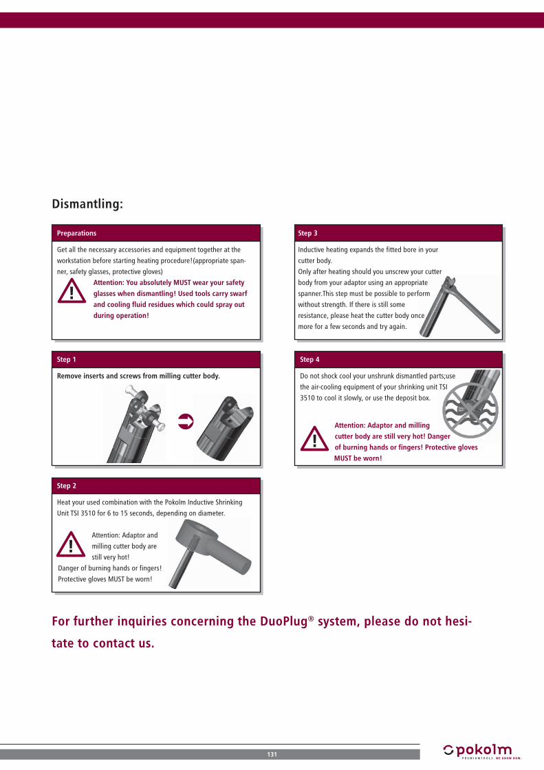
Dismantling:
Preparations
Step 1
Step 2
Step 3
Step 4
Get all the necessary accessories and equipment together at the
workstation before starting heating procedure!(appropriate span-
ner, safety glasses, protective gloves)
Heat your used combination with the Pokolm Inductive Shrinking
Unit TSI 3510 for 6 to 15 seconds, depending on diameter.
Attention: Adaptor and
milling cutter body are
still very hot!
Danger of burning hands or fingers!
Protective gloves MUST be worn!
Remove inserts and screws from milling cutter body.
Attention: Adaptor and milling
cutter body are still very hot! Danger
of burning hands or fingers! Protective gloves
MUST be worn!
Inductive heating expands the fitted bore in your
cutter body.
Only after heating should you unscrew your cutter
body from your adaptor using an appropriate
spanner.This step must be possible to perform
without strength. If there is still some
resistance, please heat the cutter body once
more for a few seconds and try again.
Do not shock cool your unshrunk dismantled parts;use
the air-cooling equipment of your shrinking unit TSI
3510 to cool it slowly, or use the deposit box.
For further inquiries concerning the DuoPlug® system, please do not hesi-
tate to contact us.
Attention: You absolutely MUST wear your safety
glasses when dismantling! Used tools carry swarf
and cooling fluid residues which could spray out
during operation!
131

ASSEMBLING INSTRUCTIONSSeal ring for CNC precision drill chuck
Two seal rings for different drill diameters are generally included in the scope of delivery of all Pokolm CNC precision drill chucks. Please observe the instructions when exchanging the seal rings or replacing them with a corresponding spare part.
Open the clamping jaws of the drill chuck with an Allen key.
Dismantle the drill chuck on the machine side until the spindle can
be freely accessed.
Insert the assembly tool in the middle of the drill chuck on the side
of the spindle until it meets resistance from the seal ring. By applying
light pressure the seal ring can now be removed by pushing it for-
ward and out through the clamping jaws.
Place the new seal ring with the hollow side facing the tool onto the
assembly tool and insert from the front through the clamping jaw up
to the seat of the seal ring.
The seal ring is held in place with an O-ring.
Seal ringAssembly tool
Disassembly:
Step 1
Assembly:
Seal ring Assembly tool
Step 2
Step 1
132
ASSEMBLING INSTRUCTIONS

ASSEMBLING INSTRUCTIONSCentering arbor and flange contact surface
In order to ensure a trouble-free insertion into the machine during centering and screwing-on the flange contact surface make sure that the centering arbor and the flange contact surface are not screwed together tightly. The fastening screw that is pro-vided is constructed in such a way that it prevents the centering arbor and the flange contact surface from becoming tightly screwed together. Please observe the following instructions:
Insert the centering arbor into the corresponding fitting of the flange
contact surface.
Insert the tightening bolt that is provided into the centering arbor
and screw into the threading of the flange contact surface with an
Allen key (10 mm) and then tighten by hand. Now the centering
arbor and the flange contact surface are connected to each other.
Screw the retaining bolt into the inside thread of the centering arbor
and tighten by hand.
The flange contact surface can now be inserted and screwed to the
machine.
Flange contact surfaceTightening bold
Assembly of the centering arbor:
Step 1
Assembly of the retaining bolt:
Centering arbor
Flange contact surfaceRetaining bolt Centering arbor
Step 2
Schritt 1
133

134
PagePage
PageCatalogue No.
Catalogue No.
Catalogue No.
NUMERICAL INDEX
INDEX
000 16 750 S 8000 16 754 S 9000 20 710 S 9700 20 714 S 10700 20 750 S 8000 20 754 S 9000 25 710 S 9700 25 714 S 10700 25 750 S 8000 25 754 S 9000 36 710 S 9708 40 780 2708 40 781 2808 60 780 27
110 12 600 3010 12 600 G 2910 16 734 S 7210 36 714 S 10710 40 780 2710 40 781 2810 60 780 2710 610 2510 630 26100 03 750 S.01 77100 03 754 S.01 88100 03 A63 S.01 52100 03 E50 S.01 45100 04 750 S.01 77100 04 754 S.01 88100 04 A63 S.01 52100 04 E50 S.01 45100 06 710 S 95100 06 714 S 105100 06 750 S 77100 06 750 SB 79100 06 754 S 88100 06 A100 S 62100 06 A63 S 52100 06 A63 SB 54100 06 E40 S 39100 06 E50 S 45100 06 EC 40 S 43100 08 601 23100 08 606 22100 08 710 S 95
100 08 714 S 105100 08 750 74100 08 750 S 77100 08 750 SB 79100 08 754 S 88100 08 A100 61100 08 A100 S 62100 08 A63 49100 08 A63 S 52100 08 A63 SB 54100 08 E50 44100 08 E50 S 45100 08 EC 40 S 43100 10 601 23100 10 603 20100 10 606 22100 10 710 S 95100 10 714 S 105100 10 750 74100 10 750 S 77100 10 750 SB 79100 10 750 ZYL 76100 10 754 86100 10 754 S 88100 10 754 ZYL 87100 10 A100 61100 10 A100 S 62100 10 A63 49100 10 A63 S 52100 10 A63 SB 54100 10 A63 ZYL 51100 10 E40 S 39100 10 E50 44100 10 E50 S 45100 10 EC 40 S 43100 12 601 23100 12 603 20100 12 606 22100 12 710 94100 12 710 S 95100 12 714 104100 12 714 S 105100 12 750 74100 12 750 S 78100 12 750 SB 79100 12 750 ZYL 76100 12 754 86
100 12 754 S 88100 12 754 ZYL 87100 12 A100 61100 12 A100 S 62100 12 A63 49100 12 A63 S 53100 12 A63 ZYL 51100 12 E40 S 39100 12 E50 44100 12 E50 S 45100 16 601 24100 16 603 21100 16 606 22100 16 710 94100 16 710 S 96100 16 710 Z 98100 16 714 104100 16 714 S 105100 16 714 Z 108100 16 750 75100 16 750 S 78100 16 750 Z 81100 16 750 ZYL 76100 16 754 86100 16 754 S 88100 16 754 Z 91100 16 754 ZYL 87100 16 A100 61100 16 A63 50100 16 A63 S 53100 16 A63 Z 55100 16 A63 ZYL 51100 16 E50 S 46100 20 710 S 96100 20 714 S 106100 20 750 S 78100 20 A63 S 53100 20 E50 S 46100 22 710.01 98100 22 714 108100 22 750 81100 22 754 91100 22 A100 63100 22 A63.01 55100 25 710 S 96100 25 714 S 106100 27 710 98

135
PageCatalogue No.
PageCatalogue No.
PageCatalogue No.
100 27 714 108100 27 750 82100 27 754 91100 27 A100 63100 27 A63 56100 3 710 101100 32 710 99100 32 714 108100 32 740 112100 32 A100 63100 40 740 113100 5 710 102100 650 26100 670 25100 680 25100 ER20 750 84100 ER20 754 92100 ER20 A63 59100 MK2 AL A63 581003 1241004 1241005 12412 40 780 2712 40 781 2812 60 780 2712 60 781 28120 08 601 23120 08 606 22120 10 601 23120 10 606 22120 12 606 22120 610 25120 650 26120 MK3 AL A63 58125 10 603 20125 10 750 74125 10 A63 49125 12 601 23125 12 603 20125 12 750 74125 12 A63 49125 16 603 21125 16 750 75125 16 750 Z 81125 16 754 86125 16 A63 50125 16 A63 Z 55130 4 710 101140 10 601 23140 10 606 22
140 12 606 22140 2 710 10115 16 730 S 6815 20 730 S 6815 20 734 S 7215 27 750 8215 27 754 91150 04 E50 S 45150 06 710 S 95150 06 714 S 105150 06 E50 S 45150 08 601 23150 08 710 S 95150 08 714 S 105150 08 E50 S 45150 10 603 20150 10 710 S 95150 10 714 S 105150 10 750 74150 10 A100 61150 10 A63 49150 10 A63 S 52150 12 601 23150 12 603 20150 12 710 94150 12 710 S 95150 12 714 104150 12 714 S 105150 12 750 74150 12 A100 61150 12 A63 49150 16 601 24150 16 603 21150 16 606 22150 16 710 94150 16 710 S 96150 16 710 Z 98150 16 714 104150 16 714 S 105150 16 714 Z 108150 16 750 75150 16 750 Z 81150 16 754 86150 16 754 Z 91150 16 A100 61150 16 A63 50150 16 A63 S 53150 16 A63 Z 55150 22 710 98150 22 714 108
150 22 750 81150 22 754 91150 22 A100 63150 22 A63 55150 27 710 98150 27 714 108150 27 754 91150 27 A100 63150 3 710 101150 32 710 99150 32 714 108150 32 740 112150 32 A100 63150 40 740 113150 5 710 102150 650 2616 40 780 2716 40 781 2816 501 12416 60 780 2716 60 781 28160 12 606 22175 12 601 23175 12 603 20175 12 A63 49175 16 603 21175 16 750 Z 81175 16 A63 50175 16 A63 Z 55180 4 710 101180 650 26
220 07 603 2020 12 600 3020 12 600 G 2920 16 600 3020 16 600 G 2920 501 12420 670 2520 680 25200 06 710 S 95200 06 714 S 105200 08 710 S 95200 08 714 S 105200 10 710 S 95200 10 714 S 105200 10 A63 S 52200 12 710 94200 12 714 104200 12 A100 61

136
PageCatalogue No.
PageCatalogue No.
PageCatalogue No.
INDEX
200 16 601 24200 16 603 21200 16 606 22200 16 710 94200 16 710 S 96200 16 710 Z 98200 16 714 104200 16 714 S 105200 16 750 75200 16 750 Z 81200 16 A100 61200 16 A63 50200 16 A63 Z 55200 22 710 98200 22 714 108200 22 740 112200 22 750 81200 22 754 91200 22 A100 63200 27 710 98200 27 714 108200 27 740 112200 27 A100 63200 3 710 101200 32 710 99200 32 714 108200 32 740 112200 40 740 113200 5 710 10225 05 E40 3825 08 730 6625 08 734 7025 08 750 7425 08 754 8625 08 A63 4925 08 E40 3825 08 E50 4425 10 603 2025 10 730 6625 10 734 7025 10 750 7425 10 754 8625 10 A63 4925 10 E40 3825 10 E50 4425 12 603 2025 12 730 6625 12 734 7025 12 750 7425 12 754 86
25 12 A63 4925 12 E50 4425 16 603 2125 16 730 6625 16 734 7025 16 750 7525 16 750 Z 8125 16 754 8625 16 754 Z 9125 16 A63 5025 16 A63 Z 5525 16 E50 4425 20 600 3025 20 600 G 2925 22 750 8125 22 754 9125 22 A63 5525 27 A63 56250 12 710 94250 12 714 104250 16 601 24250 16 606 22250 16 710 94250 16 710 Z 98250 16 714 104250 16 750 75250 16 A100 61250 16 A63 50250 22 740 112250 27 710 98250 27 740 112250 32 740 112250 4 710 101
330 12 750 DDLS 8530 12 754 DDLS 9330 12 A63 DDLS 6030 16 750 DDLS 8530 16 754 DDLS 9330 16 A63 DDLS 6030 22 750 DDLS 8530 22 754 DDLS 9330 22 A63 DDLS 6030 25 600 3030 25 600 G 2930 610 25300 12 710 94300 12 714 104300 16 601 24300 16 606 22
300 16 710 94300 16 710 Z 98300 16 714 104300 16 A100 61300 22 740 112300 27 740 112300 32 740 11235 630 26350 22 740 112350 27 740 112350 32 740 112
440 03 E25 S.01 3440 03 E40 S.01 3940 03 EC 40 S.01 4340 04 E25 S.01 3440 04 E32 S.01 3640 04 E40 S.01 3940 04 EC 40 S.01 4340 05 601 2340 06 E25 S 3440 06 E32 S 3640 06 E40 S 3940 06 EC 40 S 4340 07 603 2040 08 601 2340 08 606 2240 08 E25 S 3440 08 E32 S 3640 08 E40 S 3940 08 EC 40 S 4340 10 E25 S 3440 10 E32 S 3640 10 E40 S 3940 10 EC 40 S 4340 12 E40 S 3940 12 EC 40 S 4340 16 600 3040 16 600 G 2940 16 E40 S 4040 16 EC 40 S 4340 2 710 10140 670 2540 680 2540 740 A100 11440 ER16 E25 3540 ER20 E32 37400 22 740 112400 27 740 112400 32 740 112

137
PageCatalogue No.
PageCatalogue No.
PageCatalogue No.
45 20 600 3045 20 600 G 2945 610 25
550 03 730 S.01 6750 03 734 S.01 7150 03 750 S.01 7750 03 754 S.01 8850 03 A63 S.01 5250 03 E50 S.01 4550 04 730 S.01 6750 04 734 S.01 7150 04 750 S.01 7750 04 754 S.01 8850 04 A63 S.01 5250 04 E50 S.01 4550 05 E40 3850 06 710 S 9550 06 714 S 10550 06 730 S 6750 06 734 S 7150 06 750 S 7750 06 750 SB 7950 06 754 S 8850 06 A63 S 5250 06 A63 SB 5450 06 E50 S 4550 08 710 S 9550 08 714 S 10550 08 730 S 6750 08 734 S 7150 08 750 7450 08 750 S 7750 08 750 SB 7950 08 750 ZYL 7650 08 754 8650 08 754 S 8850 08 754 ZYL 8750 08 A100 6150 08 A63 4950 08 A63 S 5250 08 A63 SB 5450 08 A63 ZYL 5150 08 E40 3850 08 E50 4450 08 E50 S 4550 10 603 2050 10 710 S 9550 10 714 S 10550 10 730 S 67
50 10 734 S 7150 10 750 7450 10 750 S 7750 10 750 SB 7950 10 750 ZYL 7650 10 754 8650 10 754 S 8850 10 754 ZYL 8750 10 A100 6150 10 A63 4950 10 A63 S 5250 10 A63 SB 5450 10 A63 ZYL 5150 10 E40 3850 10 E50 4450 10 E50 S 4550 12 603 2050 12 710 9450 12 710 S 9550 12 714 10450 12 714 S 10550 12 730 S 6750 12 734 S 7150 12 750 7450 12 750 S 7850 12 750 SB 7950 12 750 ZYL 7650 12 754 8650 12 754 S 8850 12 754 ZYL 8750 12 A100 6150 12 A63 4950 12 A63 S 5350 12 A63 ZYL 5150 12 E50 4450 12 E50 S 4550 16 603 2150 16 710 9450 16 710 S 9650 16 710 Z 9850 16 714 10450 16 714 S 10550 16 714 Z 10850 16 730 S 6750 16 734 S 7150 16 750 7550 16 750 S 7850 16 750 Z 8150 16 750 ZYL 7650 16 754 86
50 16 754 S 8850 16 754 Z 9150 16 754 ZYL 8750 16 A100 6150 16 A63 5050 16 A63 S 5350 16 A63 Z 5550 16 A63 ZYL 5150 16 E50 4450 16 E50 S 4650 20 710 S 9650 20 714 S 10650 20 750 S 7850 20 754 S 8850 22 710 9850 22 714 10850 22 750 8150 22 754 9150 22 A100 6350 22 A63 5550 25 600 3050 25 600 G 2950 27 710 9850 27 710 DDLS 10350 27 714 10850 27 714 DDLS 10950 27 750 8250 27 754 9150 27 A100 6350 27 A63 5650 3 710 10150 32 600 3050 32 600 G 2950 32 710 9950 32 714 10850 32 A100 6350 630 2650 742 11450 743 11450 ER20 730 6950 ER20 734 7350 ER20 750 8450 ER20 754 9250 ER20 A63 5950 ER20 E40 4250 ER20 E50 48
660 05 601 2360 07 603 2060 08 601 23

138
PageCatalogue No.
PageCatalogue No.
PageCatalogue No.
60 08 606 2260 10 601 2360 10 606 2260 16 A100 S 6260 20 A100 S 6260 20 A63 S 5360 20 E50 S 4660 25 710 S 9660 25 714 S 10660 25 750 S 7860 25 754 S 8960 25 A100 S 6260 25 A63 S 5360 36 714 S 10660 610 2560 670 2560 680 2565 630 26
770 03 E40 S.01 3970 03 EC 40 S.01 4370 04 E40 S.01 3970 06 E32 S 3670 06 E40 S 3970 06 EC 40 S 4370 08 E40 S 3970 08 EC 40 S 4370 10 E40 S 3970 10 EC 40 S 4370 12 E40 S 3970 12 EC 40 S 4375 04 750 S.01 7775 04 A63 S.01 5275 06 750 S 7775 06 A63 S 5275 08 750 7475 08 750 S 7775 08 754 8675 08 A63 4975 08 A63 S 5275 08 E40 3875 08 E50 4475 10 603 2075 10 750 7475 10 750 S 7775 10 750 ZYL 7675 10 754 8675 10 754 ZYL 8775 10 A100 6175 10 A63 49
75 10 A63 S 5275 10 E40 3875 10 E50 4475 12 601 2375 12 603 2075 12 750 7475 12 750 S 7875 12 750 ZYL 7675 12 754 8675 12 754 ZYL 8775 12 A63 4975 12 A63 S 5375 12 E50 4475 16 603 2175 16 750 7575 16 750 S 7875 16 750 Z 8175 16 750 ZYL 7675 16 754 8675 16 754 Z 9175 16 754 ZYL 8775 16 A63 5075 16 A63 S 5375 16 A63 Z 5575 16 E50 4475 20 750 S 7875 22 750 8175 22 754 9175 22 A100 6375 22 A63.01 5575 27 750 8275 27 754 9175 27 A63 5675 610 25
880 05 601 2380 07 603 2080 08 601 2380 08 606 2280 10 601 2380 10 606 2280 12 606 2280 4 710 10180 630 2680 670 2580 680 25
990 2 710 10195 610 2595 630 26
A-ZBF 0,3-8 750 IC 83BF 0,3-8 A63 IC 57BF 0,3-8 E40 IC 41BF 0,3-8 E50 IC 47BF 0,5-13 710 IC 100BF 0,5-13 750 IC 83BF 0,5-13 A100 IC 64BF 0,5-13 A63 IC 57BF 0,5-13 E50 IC 47BF 2,5-16 710 IC 100BF 2,5-16 750 IC 83BF 2,5-16 A100 IC 64BF 2,5-16 A63 IC 57BF 2,5-16 E50 IC 47BF08DS04 126BF08DS08 126BF08MW 126BF13DS06 126BF13DS13 126BF13MW 126BF16DS06 126BF16DS16 126ER16 001 125ER16 1-2 31ER16 2-3 31ER16 3-4 31ER16 4-5 31ER16 5-6 31ER16 7-8 31ER16 9-10 31ER20 0,5-1 32ER20 001 125ER20 1-2 32ER20 11-12 32ER20 2-3 32ER20 3-4 32ER20 4-5 32ER20 5-6 32ER20 7-8 32ER20 9-10 32GWST-M5X8-914 124GWST-M6X10-914 124INBUS 4T 125INBUS 6T 125KBSK40-69872A 125KBSK40-69872B 126KBSK50-69872A 125KBSK50-69872B 126KMR-100A 125
INDEX
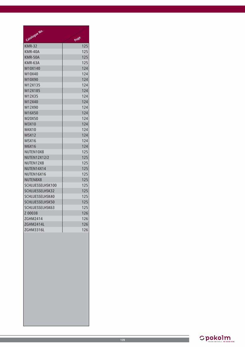
139
PageCatalogue No.
KMR-32 125KMR-40A 125KMR-50A 125KMR-63A 125M10X140 124M10X40 124M10X90 124M12X135 124M12X185 124M12X35 124M12X40 124M12X90 124M16X50 124M20X50 124M3X10 124M4X10 124M5X12 124M5X16 124M6X16 124NUTEN10X8 125NUTEN12X12/2 125NUTEN12X8 125NUTEN14X14 125NUTEN16X16 125NUTEN8X8 125SCHLUESSELHSK100 125SCHLUESSELHSK32 125SCHLUESSELHSK40 125SCHLUESSELHSK50 125SCHLUESSELHSK63 125Z 00038 126ZGHM2414 126ZGHM2414L 126ZGHM3316L 126

140
PagePage
ALPHABETICAL INDEX
INDEX
Aadditional rigidity 16-17angular frequency 7applications, recommended 16-17arbors, for morse taper adapters
58, 101-102
arbors, for shell-type milling cutters
11, 16, 55-56, 60, 63, 81-82, 85, 91, 93, 98-99, 103, 108-109, 112-113, 118
arbors, for shrinking purpo-ses
34, 36, 39-40, 43, 45-46, 52-54, 62, 67-68, 71-72, 77-80, 88-90, 95-97, 105-107
Arbors, for threaded shank end mills
11, 22-26, 38, 44, 49-51, 60-61, 66, 70, 74-76, 85-87, 93-94, 104, 118-119
arbors, HSK 100 15, 61-64, 114, 125arbors, HSK 25 14, 34-35, 125arbors, HSK 32 36-37, 125arbors, HSK 40 15, 38-43, 125arbors, HSK 50 15, 44-48, 125arbors, HSK 63 15, 49-60, 125arbors, SK 30 14, 66-69arbors, SK 40 14, 74-85, 125-126
arbors, SK 5014, 94-103, 112, 114, 125-126
arbors for thread connec-tions
11, 16, 22-26, 38, 44, 49-51, 60-61, 66, 70, 74-76, 85-87, 93-94, 104, 118-119
arbor systems for Pokolm DuoPlug®
119
assembling instructions, coolant supply tubes
128
assembling instructions, DuoPlug®
12, 130-131
Bbalance error 7-9balancing 6, 8-9
balancing grade6, 9, 41, 47, 57, 64, 83, 100, 118
ball nose end mills 10Bohrungsdurchmesser 70-73BT 30-arbors 14, 70-73BT 40-arbors 14, 86-93BT 50-arbors 14, 104-109
Ccalculation, balancing grade 7calculation example 9
cap nut 124-125cap screw 124cavities, deep 17, 27-28CD-ROM 4centering arbor 114, 133centrifugal force 7, 9
characteristics, summary
20, 22-25, 27-32, 34-39, 41-45, 47-49, 51-52, 54-55, 57-64, 66-74, 76-77, 79-81, 83-88, 90-95, 97-98, 100-101, 103-105, 107-109, 112, 114
clamping flats 8
collet chucks35, 37, 42, 48, 59, 69, 73, 84, 92
combination possibilities 10compensation mass 7component quality 9computer quotation 4concentricity 9, 12, 17, 31-32, 117
coolant supply22-24, 27-30, 34-52, 54-59, 61-64, 83, 100, 118-119
coolant supply, internal22-24, 27-30, 34-52, 54-59, 61-64, 83, 100, 119
coolant supply tubes, HSK 125, 128corrective drill hole 8customized arbors 129cutting speed 116
Ddata export 4
dense antivibration material10, 17, 68, 72, 80, 90, 97, 107
depths, large 16-17dies, small 17dimensions, slim 12dimensions, small 17DIN/ISO 1940 6DIN 2080 114DIN 6499-B 31-32DIN 69 871 66-69, 74-85, 94-103, 114DIN 912 124DIN 914 124directory 5direct spindle mounting 5, 11, 16, 112-114, 126, 133Drill Chuck 41, 47, 57, 64, 83, 100, 125drive blocks 124-125

141
PagePage
DuoPlug®10-13, 17, 20, 117, 119, 130-131
DuoPlug®, assembling 130E
eccentricity 6eccentricity of centre gravity 7end mills 10-11
ER 2032, 37, 42, 48, 59, 69, 73, 84, 92, 124
ER-collets 11
extension5, 10-11, 16, 20, 22-23, 25, 27-32, 68, 72, 80, 90, 97, 107, 129
extra hard coating 13F
fatigue strength 13fax purchase order 120fine thread 12finishing end mills 23-24finishing operations 13, 17fits, backlash-free 13, 20flange contact surface 12flange contact surface, high accuracy
13
form A, HSK 8, 49-64, 114, 125, 128form C, HSK 43form E, HSK 34-48, 57, 64, 128formulas 7frequency 7
Hheat resistance 13
high-speed machining9, 20, 22-24, 35, 37, 42, 48, 59, 69, 73, 84, 92
hollow taper shank (HSK)3, 5-6, 8-11, 15, 34-64, 114, 118, 125, 128
HSK 100 15, 61-64, 114, 125HSK 25 15, 34-35HSK 32 36-37, 125HSK 40 15, 38-43, 125HSK 50 15, 44-48, 125HSK 63 15, 49-60, 125HSK-accessories 125HSK forms & designs, over-view
8, 128
Iincorporated insert 11, 130indexable inserts 130-131indexable inserts, incorpo-rated
11, 130
inquiry form 120
insert seat, reproducible 13inspection 116
internal coolant supply22-24, 27-30, 34-52, 54-59, 61-64, 83, 100, 119
J
JIS-standard68, 70-73, 80, 86-93, 97, 104-109
L
latest items
2, 22, 31, 34-35, 37, 41, 47, 57, 60, 62, 64, 66-73, 83, 85, 87, 90, 93, 100, 103, 107, 109, 116, 132
long overhangs 13, 112, 114long series 13, 17, 112, 114, 116
M
M 10-connection20, 22-23, 25, 27-30, 38, 44, 49, 51, 61, 66, 70, 74, 76, 86-87, 124
M 12-connection20, 22-23, 25, 27-30, 44, 49, 51, 60-61, 66, 70, 74, 76, 85-87, 93-94, 104, 124
M 16-connection20-30, 44, 50-51, 60-61, 66, 70, 75-76, 85-87, 93-94, 104, 124
M 5-connection 23-24, 28-30, 38, 124M 7-connection 20-21
M 8-connection22-23, 25-30, 38, 44, 49, 51, 61, 66, 70, 74, 76, 86-87, 129
machine building 116machine joints 3, 117machine spindle 9, 112, 114machining situations, deep 129machining time 116machining time, reduced 116mass axis 8-9milling feed rates, effective 116model making 116modification 2morse taper adapters 58, 101-102morse taper shank 10-11, 58, 101-102mould making 116MTS 2-adapters 25, 58, 101, 124MTS 3-adapters 25, 58, 101, 124MTS 4-adapters 25-26, 101, 124MTS 5-adapters 26, 102, 124
Ooperational life time, longer 13optimization 12overhang, long 13, 112, 114

142
PagePage
INDEX
P
precision
12-13, 17, 20, 22-24, 31-32, 34-52, 54-59, 61-64, 66-74, 76-84, 86-88, 90-92, 94-98, 100-102, 104-108, 117
precision-collets 31-32pre-finishing operations 16processing, conventional 9process reliability 13profiles, deep 16purchase order form 118-120
QQuadworx® 10-11quality 122quality characteristics 6
Rreduction 10-11, 16, 28reinforced design 54, 79remaining balance value 6-7reproduction 2retention forces 12-13, 17, 20, 22retention knob 125-126revolution 6-7, 116-117rigidity 12-13, 16-17, 112, 114rigidity requirements, extreme
16
rotary transmission leadt-hrough
60, 85, 93, 103, 109
rotational axis 8rotor weight 7roughing 13, 16roughing operations 13, 17round inserts 10
Sscrews 12, 124, 128-129screws for drive blocks 124
seal ring41, 47, 57, 64, 83, 100, 125-126, 128
service 4, 129set screw 124shank, reinforced 17
shape, slim12, 16, 41, 47, 57, 64, 83, 100
shell-type combinations 11shell-type extensions 11, 129
shell-type milling cutters11, 55-56, 60, 63, 81-82, 85, 91, 93, 98-99, 103, 108-109, 112-113, 118
short taper 10, 17short taper connection 11
shrink connection 11, 13shrink fit-zone 12
shrink-grip
16-17, 34, 36, 39-40, 43, 45-46, 52-54, 62, 67-68, 71-72, 77-80, 88-90, 95-97, 105-107
shrinking adapters 10
shrinking arbors
9-11, 16-17, 34, 36, 39-40, 43, 45-46, 52-54, 62, 67-68, 71-72, 77-80, 88-90, 95-97, 105-107, 117-118
shrinking technology 5, 116-117shrink thread 12SK 30 14, 66-69, 124.125SK 40 14, 74-85, 125-126
SK 5014, 94-103, 112, 114, 125-126
slots, deep 17Slotworx® 10-11
solid carbide10, 16-17, 68, 72, 80, 90, 97, 107, 119
solid carbide adapters 20, 22solutions 16-17, 116, 129space, limited 17space availability, narrow 16Spanner 125-126spanner for ER 20-collet-chuck-tightning nut
124
spare parts 116, 132special materials 13spigot-diam. 16 55, 81, 91, 98, 108spigot-diam. 22 55, 63, 81, 91, 98, 108, 112spigot-diam. 27 56, 63, 82, 91, 98, 108, 112spigot-diam. 32 63, 99, 108, 112spigot-diam. 40 113spindle systems 5, 116
steep taper (SK)3, 5-6, 8, 10-11, 14, 66-88, 90-109, 112, 114, 118, 125-126
surface finish 17, 116-117T
tapered 16, 28technical data 12technology 12-13tensile strength 13threaded bushes 126threaded combinations 11-13
threaded shank end mill bodies
11, 22-26, 38, 44, 49-51, 60-61, 66, 70, 74-76, 85-87, 93-94, 104, 118-119

143
Page
thread socket-shell type adapters
129
tolerances 12tool costs, reduced 13tool diameter 16-17tool making 116tool system 10-11, 13toric end mills 10torque 117Trigaworx® 10TSI 3510 130-131
UUniworx® 10
VVc 116vertical walls 13, 16-17vibrations 9, 13, 17vibrations avoidance 17
Wwalls, vertical 13, 16-17Weldon 8
Zzero-reach arbors 17, 68, 72, 80, 90, 97, 107z-travel, limited 17

NOTES
144
NOTES

NOTES
145

NOTES
146
NOTES

QUICKFINDER
M 5 M 8 M 10 M 12 M 16
5,5 8,5 10,5 12,5 17,0
7 15 30 50 100
16 22 27 32 40
M 8 M 10 M 12 M 16 M 20
d1 d2 r
h8 h6 f8
2 - 5 6 + 8 10 12 + 14 16 + 18
28 36 40 45 48
20 25 32 + 36
50 56 60
The arbor dimensions d4 and l3 (see illustration at left) are calculated up to the theoretical point of intersection between arbor taper and collar.Please take the radius R (5-8 mm depending on arbor type) into account for practical use.
Thread size
Pilot diameter in mm
diam. of shank (DIN 6535) d2 h6
diam. of shank (DIN 6535) d2 h6
Length fit zone in mm
Fixing screw
length of shank (DIN 6535) l2
length of shank (DIN 6535) l2
incorporated inserttoric tool
dense antivibration material
clamping flat
arbors with zero reach
7° positive axial rake angle DuoPlug®
17° positive axial rake angle
12° positive axial rake angle shimconcave moulding
stainless- acid- and heat resistant
internal coolant supplyworking depthSolid Carbide especially suitable f. non-ferr. materialssuitable for high-speed machiningchamfer on requestwet machining possible2-point contact milling stock item, subject to confirmationdry machining possiblewet machining required available as long as stock lastsfor direct spindle mountingdry machining required new itemlong seriesbalance grade
Starting torque in Nm
*this usable length appears through deduction of the DIN-shank-length (l2 according to DIN 6535) from the overall length l1 of the end mill or of the solid carbide adapters. See table above.
Fit zone diam. of threaded shank end mill bodies:
Thread sizes for Shell-type arbors:
Theoretical d4 and l3:
Tolerances for Solid carbide end mills:
Theoretical usable end mill length of Solid carbide end mills in mm*:
Features:
+2
- 0
+2
- 0
147