Embed Size (px)
Citation preview
© 2012. S. Vasileiadis, Z. Ziaka, M. Tsimpa & E. M. Vasileiadou. This is a research/review paper, distributed under the terms of the Creative Commons Attribution-Noncommercial 3.0 Unported License http://creativecommons.org/licenses/by-nc/3.0/), permitting all non commercial use, distribution, and reproduction in any medium, provided the original work is properly cited.
Global Journal of Researches in Engineering Chemical Engineering Volume 12 Issue 1 Version 1.0 Year 2012 Type: Double Blind Peer Reviewed International Research Journal Publisher: Global Journals Inc. (USA) Online ISSN: 2249-4596 Print ISSN:0975-5861
New Biogas Renewable System for Combined Sofc-Electricity Generation with a Membrane Reactor
By S. Vasileiadis, Z. Ziaka, M. Tsimpa & E. M. Vasileiadou Hellenic Open University, Patras
Abstract - This paper presents and analyzes a new biogas based catalytic reforming-processing system for the conversion of gaseous hydrocarbons (coming from manure type anaerobic digesters) such as methane into hydrogen and carbon oxide mixtures. The exit
synthesis gas (syn-gas) is introduced to
power effectively high temperature fuel cells such as SOFC types for combined efficient electricity generation.
Keywords : Biogas reforming, fuel cell, membrane reactor, catalytic reactor, SOFC, renewable energy.
GJRE-C Classification : FOR Code
: 090405
New Biogas Renewable System for Combined Sofc-Electricity Generation with a Membrane Reactor
Strictly as per the compliance and regulations of:
New Biogas Renewable System for Combined Sofc-Electricity Generation with a Membrane
Reactor
Abstract - This paper presents and analyzes a new biogas based catalytic reforming-processing system for the conversion of gaseous hydrocarbons (coming from manure type anaerobic digesters) such as methane into hydrogen and carbon oxide mixtures. The exit synthesis gas (syn-gas) is introduced to power effectively high temperature fuel cells such as SOFC types for combined efficient electricity generation.
Moreover, this research targets on the description and design aspects of permreactors (permeable reformers) carrying the same type of renewable-biogas reforming reactions. The goals of such a research include turnkey system and process development for the biogas based power generation and fuel cell industries. The proper utilization of biogas and waste type resources (coming from manure type anaerobic digesters) for green-type/renewable power generation with increased processing capacity and efficiency via SOFCs is introduced as well. Pollution reduction is under additional design benefit in the described catalytic processors-fuel cell systems, at the same time. Three different reactor configurations are examined and compared. The use of a membrane reformer and of a catalytic membrane reformer offer better hydrogen and syngas yields and methane conversions than the corresponding non-membrane plug flow reactor. Keywords : biogas reforming, fuel cell, membrane reactor, catalytic reactor, SOFC, renewable energy.
I. Introduction
n our earlier IASTED and ACS presentations (PGRES ’02, Marina Del Ray, CA; Modeling and Simulation, ‘03, Palm Springs, CA; ACS-Fuel Chemistry ’02,
Boston, MA) we discussed about preliminary findings and results of catalytic processors for the steam reforming of methane, natural gas, and biogas, for use in fuel cell systems such as SOFC types [1].
The recent communication continues this research introducing the so-called “Biogas power” and “Bio-Energy” systems. The use of biogas mixtures (manure based generated feedstocks) as sources for electricity and heat generation using fuel cells of the SOFC type are studied here. Use of manure based gases rich in methane coming from anaerobic digesters, for the production of intermediate synthesis gas is an
Author σ
:
International Hellenic University, Thermi-Thessaloniki, GR, 57001.
E-mail : [email protected]
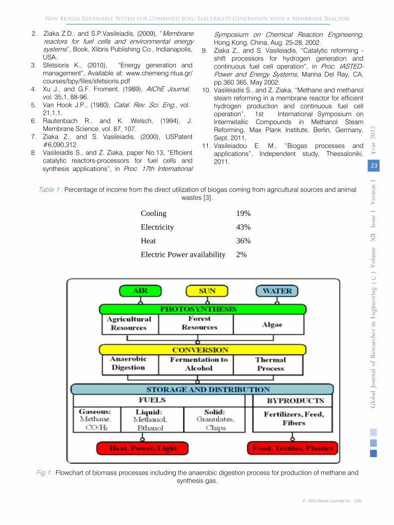
attractive route in “green power” and “biogas/manure energy” based systems [2]. There is a recent emphasis on the development and commercialization of such SOFC systems for electricity and heat generation applications. Such installations begin to exist currently mainly in US, Europe, Japan, China and other developing countries. Fig.1 below, shows the itemized distribution of biogas energy-applications which is coming from various renewable sources [3].
Fig.1 shows the products that are coming from the biomass treatment process, especially those coming from the anaerobic digestion. In our case however the feedstock is animal wastes and not agricultural or forest biomass.
Such biomass-energy systems require the development and use of an effective catalytic reformer utilizing active metals such as Ni, Rh, Cr, or bimetallic combinations of those. Earth metal enrichment in the catalyst such as with Ca, Mg, La and K promotes the catalyst stability on stream and minimizes deactivation from carbon deposition, especially in the reactor inlet [1,2,4,5].
The reformer used can be a fixed bed catalysis- reactor or a permreactor using membrane type materials as reactor walls. Use of a permreactor creates a two outlet reaction system which carries the synthesis gas product at different compositions. The permeate stream is richer in hydrogen and less rich in carbon oxides, by the use of hydrogen selective membranes such as microporous inorganics (e.g., alumina, titania based) or metal alloys (Pd/Ag, Pd/Cu). One or both of the outlet gas streams can be used as feed in the accompanied fuel cell/SOFC. Use of the permreactor increases the conversion of the reactant biogases in the reactor due to the separation of products. This increased shift in conversion yields the required quantity of synthesis gas product for the fuel cell at a lower operation temperature than the counterpart fixed bed (impermeable) reactor [2].Process operation at a lower temperature is beneficial for increasing the reactor and catalyst life time and for reducing the endothermic heating load (Btu/hr) of the endothermic reformer. Below, we give design emphasis in both reformer configurations for the generation and delivery of hydrogen rich synthesis gas into the accompanied solid oxide fuel cell.
I Globa
l Jo
urna
l of R
esea
rche
s in E
nginee
ring
Volum
e X
II Issue
vvvvI
Versio
n I
19
(DDDD
)c
© 2012 Global Journals Inc. (US)
ea
r 20
12
Y
S. Vasileiadis α, Z. Ziaka σ, M. Tsimpa ρ & E. M. VasileiadouѠ
Author α ρ : Hellenic Open University, Patras, GR, 26335,
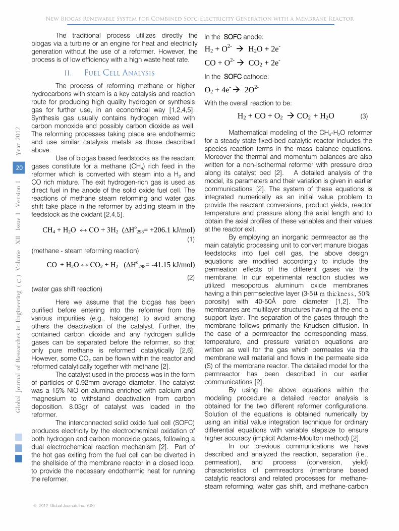
The traditional process utilizes directly the biogas via a turbine or an engine for heat and electricity generation without the use of a reformer. However, the process is of low efficiency with a high waste heat rate.
II.
Fuel Cell Analysis The process of reforming methane or higher
hydrocarbons with steam is a key catalysis and reaction route for producing high quality hydrogen or synthesis gas for further use, in an economical way [1,2,4,5]. Synthesis gas usually contains hydrogen mixed with carbon monoxide and possibly carbon dioxide as well. The reforming processes taking place are endothermic and use similar catalysis metals as those described above.
Use of biogas based feedstocks as the reactant gases constitute for a methane (CH4) rich feed in the reformer which is converted with steam into a H2
and CO rich mixture. The exit hydrogen-rich gas is used as direct fuel in the anode of the solid oxide fuel cell. The reactions of methane steam reforming and water gas shift take place in the reformer by adding steam in the feedstock as the oxidant [2,4,5].
CH4 + H2O ↔ CO + 3H2 (∆Ho298= +206.1 kJ/mol)
(1) (methane - steam reforming reaction)
CO + H2O ↔ CO2 + H2 (∆Ho298= -41.15 kJ/mol)
(2) (water gas shift reaction)
Here we assume that the biogas has been purified before entering into the reformer from the various impurities (e.g., halogens) to avoid among others the deactivation of the catalyst. Further, the contained carbon dioxide and any hydrogen sulfide gases can be separated before the reformer, so that only pure methane is reformed catalytically [2,6]. However, some CO2 can be flown within the reactor and reformed catalytically together with methane [2].
The catalyst used in the process was in the form of particles of 0.92mm average diameter. The catalyst was a 15% NiO on alumina enriched with calcium and magnesium to withstand deactivation from carbon deposition. 8.03gr of catalyst was loaded in the reformer.
The interconnected solid oxide fuel cell (SOFC) produces electricity by the electrochemical oxidation of both hydrogen and carbon monoxide gases, following a dual electrochemical reaction mechanism [2]. Part of the hot gas exiting from the fuel cell can be diverted in the shellside of the membrane reactor in a closed loop, to provide the necessary endothermic heat for running the reformer.
H2 + O2- H2O + 2e-
CO + O2- CO2 + 2e-
In the SOFC cathode:
O2 + 4e- 2O2-
With the overall reaction to be:
H2 + CO + O2 CO2 + H2O (3)
Mathematical modeling of the CH4-H2O reformer
for a steady state fixed-bed catalytic reactor includes the species reaction terms in the mass balance equations. Moreover the thermal and momentum balances are also written for a non-isothermal reformer with pressure drop along its catalyst bed [2]. A detailed analysis of the model, its parameters and their variation is given in earlier communications [2]. The system of these equations is integrated numerically as an initial value problem to provide the reactant conversions, product yields, reactor temperature and pressure along the axial length and to obtain the axial profiles of these variables and their values at the reactor exit.
By employing an inorganic permreactor as the main catalytic processing unit to convert manure biogas feedstocks into fuel cell gas, the above design equations are modified accordingly to include the permeation effects of the different gases via the membrane. In our experimental reaction studies we utilized mesoporous aluminum oxide membranes having a thin permselective layer (3-5 m thicknes s , 50% porosity) with 40-50Å pore diameter [1,2]. The membranes are multilayer structures having at the end a support layer. The separation of the gases through the membrane follows primarily the Knudsen diffusion. In the case of a permreactor the corresponding mass, temperature, and pressure variation equations are written as well for the gas which permeates via the membrane wall material and flows in the permeate side (S) of the membrane reactor. The detailed model for the permreactor has been described in our earlier communications [2].
By using the above equations within the modeling procedure a detailed reactor analysis is obtained for the two different reformer configurations. Solution of the equations is obtained numerically by using an initial value integration technique for ordinary differential equations with variable stepsize to ensure higher accuracy (implicit Adams-Moulton method) [2].
In our previous communications we have described and analyzed the reaction, separation (i.e., permeation), and process (conversion, yield) characteristics of permreactors (membrane based catalytic reactors) and related processes for methane-steam reforming, water gas shift, and methane-carbon
New Biogas Renewable System for Combined Sofc-Electricity Generation with a Membrane ReactorGloba
l Jo
urna
l of R
esea
rche
s in E
nginee
ring
Volum
e X
II Issue
vv v I V
e rsio
n I
20
(DDDD
)c
© 2012 Global Journals Inc. (US)
ea
r 20
12
Y
In the SOFC anode:
µ
dioxide reforming reactions including catalysis and membrane materials characteristics [2]. These effective and versatile catalytic systems were applied for pure hydrogen (H2), H2
and CO2, and H2
and CO
(syn-gas) generation to be used as fuel gas for power generation or as synthesis gas for production of specialty chemicals (such as methanol and higher hydrocarbons) [1,2].
The interconnected or integrated solid oxide fuel cell is fed directly by the fuel gas generated by the described reformers. The focus of our studies includes solutions in a number of problems associated with the installation, operation, and mass, energy conservation of the entire fuel cell and membrane-processing unit. The economic feasibility of the overall fuel cell installation is correlated with high efficiency (e.g., 50%-75% for advanced units) and high current density output (A/cm2), increased system reliability for continuous dispersed power generation, and reduced plant installation, operation and maintenance cost. These targets combined with virtual elimination of pollution by use of fuel cells in stationary (e.g., central and remote power stations) and mobile/transportation (e.g., automobile) sources make this technology highly applicable and attractive. Clean fuel cell power minimizes NOx, CO, and hydrocarbon species in the emissions [2].
III.
Results and Discussion
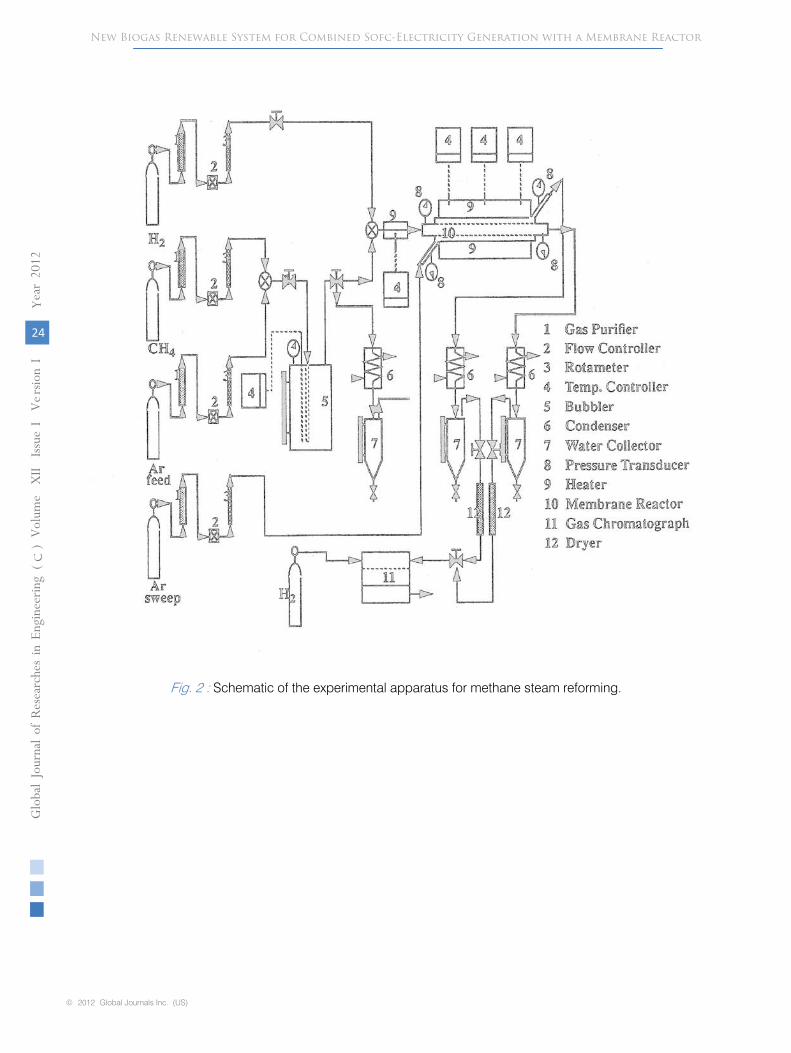
The apparatus used in the experiments consists
of mass flow controllers, a bubbler to generate steam for the reaction, the reactor housing wherein the plug flow reactor or the membrane reactor was placed. The apparatus with its details is shown in Fig 2. The reactor is equipped with thermocouples to read the temperature and with pressure transducers to read the pressure. At the exit of the reactor the apparatus consists of steam traps and a gas chromatograph to analyze the exit stream. The gas chromatograph operates in the TCD mode and is equipped with a porapack Q column for the gas analysis.
The idea of biogases utilization, coming from manure-type anaerobic digesters, within the reformer, constitutes an innovative approach in previous attempts for direct use of those feedstocks for power generation [6]. There are important renewable resources of biogas feedstocks today generated from the large herds of farm animals grown in local and remote farms.
The gas that exits from the proper treatment of manure in anaerobic digesters is rich in methane and carbon dioxide, and constitutes the proper mixture for direct conversion into the described reformer/SOFC system. As the flowrate of the manure biogases increases (for larger sites and treatment systems) a larger capacity reformer and fuel cell are required to handle the conversion; consecutively, the final SOFC power output (kW/cm2) increases as well.
The table 1 shows the percentage of income from the direct utilization of biogases coming from
agricultural and farm animal waste sources. It shows the different energy utilization of used biogas in terms of percentage [3].
Fig.1 is a useful flowchart of the biomass conversion process. It includes the anaerobic digestion process which yields methane and synthesis gas products.
The schematic of the experimental apparatus wherein the conversion to synthesis gas is taking place is shown in details in Fig.2.
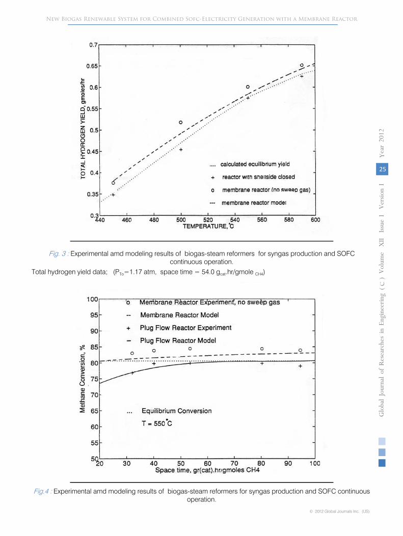
The performance of two types of reformers for the specific reactions is described. Hence, Fig.3 shows the total hydrogen yield produced from these reactions within the reformer and specifically at the reformer exit as function of the reaction temperature. We report results from a membrane type reformer and from a conventional (non-membrane) plug flow type reformer. The membrane reformer exceeds the non-membrane reformer in the total hydrogen yield and this is also shown by the accompanied modeling results which simulate well the experimental membrane reformer data. Moreover, the plug flow type reformer produces
results that are very close to the calculated equilibrium hydrogen yields which are calculated at the tubeside (T) reaction conditions. Hydrogen produced under these conditions is directed in the fuel cell anode to drive the electrochemical reactions discussed above. The feed composition in the tubeside of the membrane reformer was maintained at CH4:
H2O:
Ar:
H2
= 1:
7:
1:
0.75 . Ar gas was added initially in the feed as a diluent to examine the effect of diluting the methane/biogas feed. The space time of
the reactor tubeside was maintained at 54.0 grcat.hr/gmoleCH4. The reaction temperature range examined in the two reactors was varied from 450-590oC. The pressure in the tubeside of the reformers where the catalyst lies was maintained at about 2-3 psig (1.17atm) during the course of the experiments.
Methane conversion data at various reactor space times are included as well. This data is indicative of the performance of the catalytic methane steam reforming reaction within the reformers. The reaction conditions remained the same as with the above plot (hydrogen yield data). Thus, Fig.4 below, shows
methane conversion versus space time data for the production of H2
and CO syngas (fuel gas). The operation took place at a constant temperature of 550oC. The data is referred to two types of reformers and it is accompanied by simulation fittings by the numerical models developed and described above. It is interesting to notice that the membrane reactor data exceeds both the plug flow reactor and the equilibrium conversion data. The membrane reactor therefore produces more hydrogen and syngas for the joint fuel cell system (SOFC) at various methane inlet flowrates.
New Biogas Renewable System for Combined Sofc-Electricity Generation with a Membrane Reactor
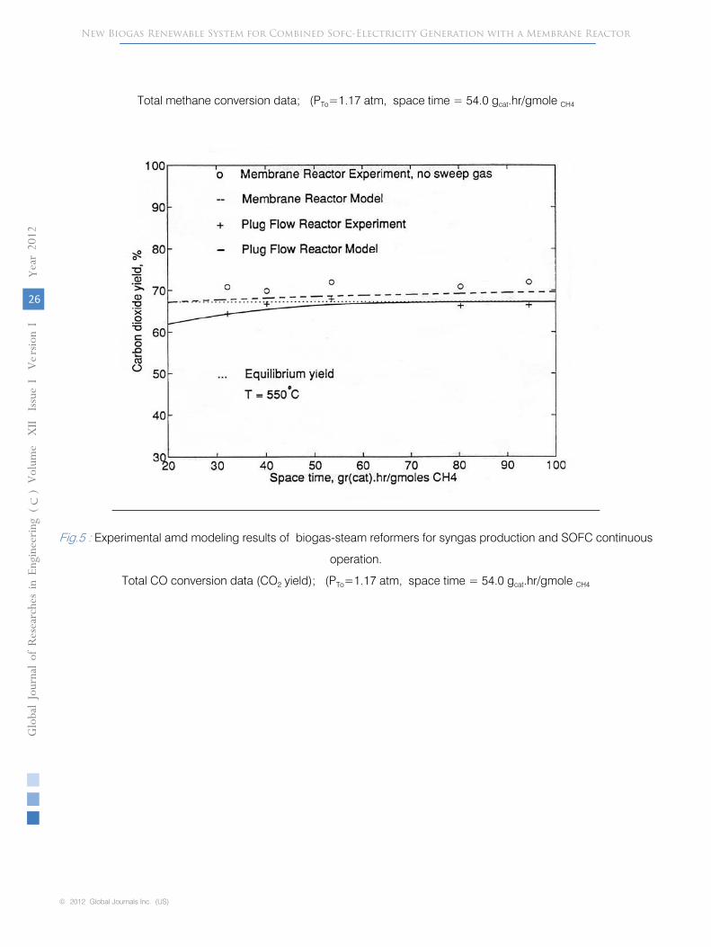
The beneficial increase in CO2 yield with the use of the membrane reformer is shown in Fig.5 below, in comparison with the other data. The CO2 yield is
Globa
l Jo
urna
l of R
esea
rche
s in E
nginee
ring
Volum
e X
II Issue
vvvvI
Versio
n I
21
(DDDD
)c
© 2012 Global Journals Inc. (US)
ea
r 20
12
Y
indicative of the extent of the water gas shift reaction (reaction (2)). The CO2
yield also corresponds to the CO conversion according to reaction (2). As one can observe, there is a good agreement by the modeling results (simulation lines) to the experimental CO2
yield data. The reaction conditions are the same with those described above. The above plots (Figs. 3, 4, 5) are shown the type of syngas (in terms of composition) which is entering into the SOFC system for electricity generation according to reactions (3), [1,2].
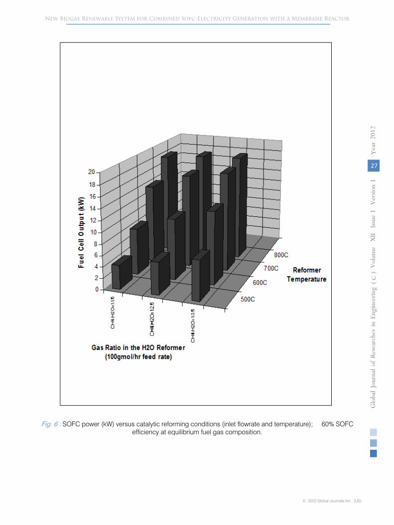
The included data shows that fuel gas rich in H2
and CO compounds can be produced from the described reformers and especially from the membrane reformer for the continuous operation and electricity generation of the SOFC. Another related plot is shown in Fig.6. It shows the generated power by the SOFC for various feed ratios and reforming conditions (i.e., reaction temperature, inlet feed composition). The plot assumes a 60% fuel cell efficiency at equilibrium fuel gas composition according to reactions (1) and (2). As the steam to methane ratio is increased in the inlet the power output is increased as well. Higher power outputs (kW) can be achieved usually between 600-800∙C.
Finally, Table 2 below presents a summary of specifications from a medium biogas processing plant (farm-animal wastes plant) for energy cogeneration. The table shows details on the energetic distribution outcome of the entire plant (e.g., 60% electricity generation efficiency for the SOFC). Τhe data refers to 4,420 swines as the total number of farm animals. This table is included for comparison purposes, in order to provide the potential of the newly described biogas to SOFC unit. It is important to
say that the electricity generated by the SOFC (assuming a 60% efficiency) can cover the needs of the farm and any excess electricity can be sold in the nearby electrical network. Moreover, the useful heat from the SOFC can cover the heating needs of the
farm (e.g., via a boiler) and those of the endothermic reformer.
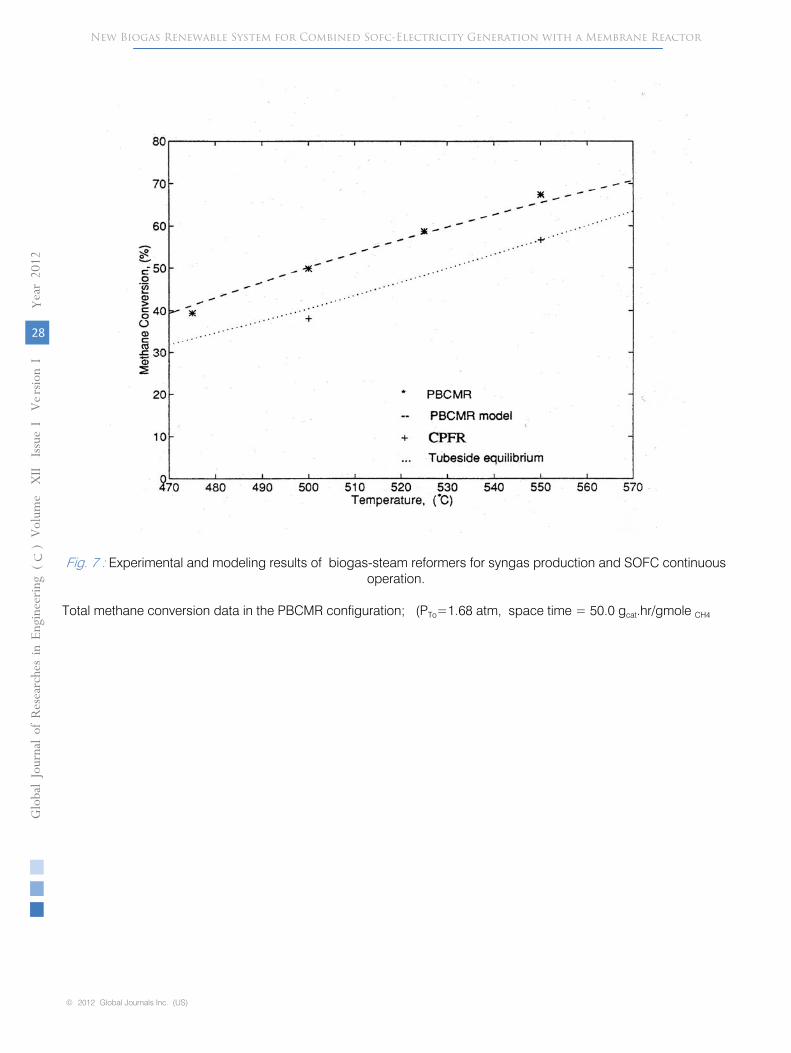
Two more figures are also shown below for the socalled PBCMR configuration. In these plots the membrane was also rendered catalytic by the incipient wetness method. A solution of NiNO3
was used to impregnate the ceramic membrane tube. The data shown in Figs. 7 and 8 was taken under these conditions. It is important that the PBCMR (packed bed catalytic membrane reactor) exceeds substantially in both conversion and yield the CPFR (catalytic plug flow reactor) data. The PBCMR data are also higher than the equilibrium calculated conversions and yields. These facts are attributed to the use of the catalytically impregnated membrane as the reactor of the system. The feed composition in the tubeside
of the membrane reformer was maintained at CH4:
H2O:
H2
= 1:
4:
0.20. The space time of the reactor tubeside was maintained at about 50.0 grcat.hr/gmoleCH4. The reaction temperature range examined in the two reactors was varied from
475-550∙C. The pressure in the tubeside of the reformers where the catalyst lies was maintained at about 10 psig (1.68atm) during the course of the experiments. The developed computational model for the PBCMR shows a pretty good agreement with the experimental membrane reactor data. Thus, the catalytic impregnation of the membrane is an additional advantage of the described system by offering higher hydrogen yields and methane conversions.
IV.
Conclusions
In this paper, it is shown that the operation of high temperature SOFCs/fuel cells can be coupled with reforming reactors of biogases. The SOFCs can operate in series or integrated with a catalytic reformer or a membrane reformer which convert biogas into fuel gas at various operating conditions. Biogases are rich in CH4
and are converted catalytically into a H2
and CO mixture suitable for the continuous operation of the SOFC unit. Our reactors have been also simulated by computational models which account for the reaction and hydrogen separation in the permeable reformers. Various operating conditions in the permeable reformers have been tested by these models. The membrane based permreactor has shown to offer better hydrogen yields and better methane conversions than the counterpart fixed bed based reactor. Among the membrane reactors examined the PBCMR found to perform superior than the simple (non-catalytic) membrane reactor. This happens most probably due to the catalytic membrane contribution as well.
Essential distributed power generation within a wider power grid can be accomplished through this design, which can cover the local needs of municipal and remote areas. Fuel cell power relates to the reformer conversion and the efficient utilization of the syngas by the fuel cell. In addition, the waste heat from the conversion of syngas to electricity can be decreased with the fuel cell operation, especially with this of high efficiency SOFCs. Moreover, fuel cell/SOFC continuous operation and power generation from biogases contribute to the pollution minimization, higher power density and efficiency in comparison with conventional power operations. With the use of clean SOFC power, we can also minimize NOx, CO, and hydrocarbon species from the emissions of such stationary biogas power construction.
References Références Referencias
1.
Vasileiadis S., and Z. Ziaka, (2002), “Catalytic reactor configurations for hydrogen generation and inline fuel cell operation”, in Proc.: Advances in Hydrogen Energy, American Chemical Society, Fuel
New Biogas Renewable System for Combined Sofc-Electricity Generation with a Membrane Reactor
Chemistry Division, Vol.47, No.2, Boston, MA, Aug.18-24.
Globa
l Jo
urna
l of R
esea
rche
s in E
nginee
ring
Volum
e X
II Issue
vv v I V
e rsio
n I
22
(DDDD
)c
© 2012 Global Journals Inc. (US)
ea
r 20
12
Y
systems”, Book, Xlibris Publishing Co., Indianapolis, USA.
3.
Sfetsioris K., (2010), “Energy generation and management”, Available at:
www.chemeng.ntua.gr/
courses/bpy/files/sfetsioris.pdf
4.
Xu J., and G.F. Froment, (1989), AIChE Journal, vol. 35,1, 88-96.
5.
Van Hook J.P., (1980), Catal. Rev. Sci. Eng.,
vol. 21,1,1.
6.
Rautenbach R., and K. Welsch, (1994), J. Membrane Science, vol. 87, 107.
7.
Ziaka Z., and S. Vasileiadis, (2000), USPatent #6,090,312.
8.
Vasileiadis S., and Z. Ziaka, paper No.13, “Efficient catalytic reactors-processors for fuel cells and synthesis applications”, in Proc.
17th International
Symposium on Chemical Reaction Engineering, Hong Kong, China, Aug. 25-28, 2002.
9.
Ziaka Z., and S. Vasileiadis, “Catalytic reforming -shift processors for hydrogen generation and continuous fuel cell operation”, in Proc. IASTED-Power and Energy Systems, Marina Del Ray, CA, pp.360 365, May 2002.
Table 1 : Percentage of income from the direct utilization of biogas coming from agricultural sources and animal
wastes [3].
New Biogas Renewable System for Combined Sofc-Electricity Generation with a Membrane Reactor
2. Ziaka Z.D., and S.P.Vasileiadis, (2009), “Membrane reactors for fuel cells and environmental energy
Electric Power availability 2%
Cooling 19%
Electricity 43%
Heat 36%
Fig.1 : Flowchart of biomass processes including the anaerobic digestion process for production of methane and synthesis gas.
Globa
l Jo
urna
l of R
esea
rche
s in E
nginee
ring
Volum
e X
II Issue
vvvvI
Versio
n I
23
(DDDD
)c
© 2012 Global Journals Inc. (US)
ea
r 20
12
Y
10. Vasileiadis S., and Z. Ziaka, “Methane and methanol steam reforming in a membrane reactor for efficient hydrogen production and continuous fuel cell operation”, 1st International Symposium on Intermetallic Compounds in Methanol Steam Reforming, Max Plank Institute, Berlin, Germany, Sept. 2011.
11. Vasileiadou E. M., “Biogas processes and applications”, Independent study, Thessaloniki, 2011.
New Biogas Renewable System for Combined Sofc-Electricity Generation with a Membrane Reactor
Fig. 2 : Schematic of the experimental apparatus for methane steam reforming.
Globa
l Jo
urna
l of R
esea
rche
s in E
nginee
ring
Volum
e X
II Issue
vv v I V
e rsio
n I
24
(DDDD
)c
© 2012 Global Journals Inc. (US)
ea
r 20
12
Y
New Biogas Renewable System for Combined Sofc-Electricity Generation with a Membrane Reactor
I V
ersio
n I
25
© 2012 Global Journals Inc. (US)
ea
r 20
12
Y
Fig. 3 : Experimental amd modeling results of biogas-steam reformers for syngas production and SOFC continuous operation.
Total hydrogen yield data; (PTo=1.17 atm, space time = 54.0 gcat.hr/gmole CH4)
Globa
l Jo
urna
l of R
esea
rche
s in E
nginee
ring
Volum
e X
II Issue
vvvv(DDDD
)c
Fig.4 : Experimental amd modeling results of biogas-steam reformers for syngas production and SOFC continuous operation.
Globa
l Jo
urna
l of R
esea
rche
s in E
nginee
ring
Volum
e X
II Issue
v I V
e rsio
n I
26
()
c
© 2012 Global Journals Inc. (US)
ear 20
12
YNew Biogas Renewable System for Combined Sofc-Electricity Generation with a Membrane Reactor
Total methane conversion data; (PTo=1.17 atm, space time = 54.0 gcat.hr/gmole CH4
Fig.5 : Experimental amd modeling results of biogas-steam reformers for syngas production and SOFC continuous
operation.
Total CO conversion data (CO2 yield); (PTo=1.17 atm, space time = 54.0 gcat.hr/gmole CH4
New Biogas Renewable System for Combined Sofc-Electricity Generation with a Membrane Reactor
Fig. 6 : SOFC power (kW) versus catalytic reforming conditions (inlet flowrate and temperature); 60% SOFC efficiency at equilibrium fuel gas composition.
Globa
l Jo
urna
l of R
esea
rche
s in E
nginee
ring
Volum
e X
II Issue
vvvvI
Versio
n I
27
(DDDD
)c
© 2012 Global Journals Inc. (US)
ea
r 20
12
Y
New Biogas Renewable System for Combined Sofc-Electricity Generation with a Membrane Reactor
Fig. 7 : Experimental and modeling results of biogas-steam reformers for syngas production and SOFC continuous operation.
Total methane conversion data in the PBCMR configuration; (PTo=1.68 atm, space time = 50.0 gcat.hr/gmole CH4
Globa
l Jo
urna
l of R
esea
rche
s in E
nginee
ring
Volum
e X
II Issue
vv v I V
e rsio
n I
28
(DDDD
)c
© 2012 Global Journals Inc. (US)
ea
r 20
12
Y
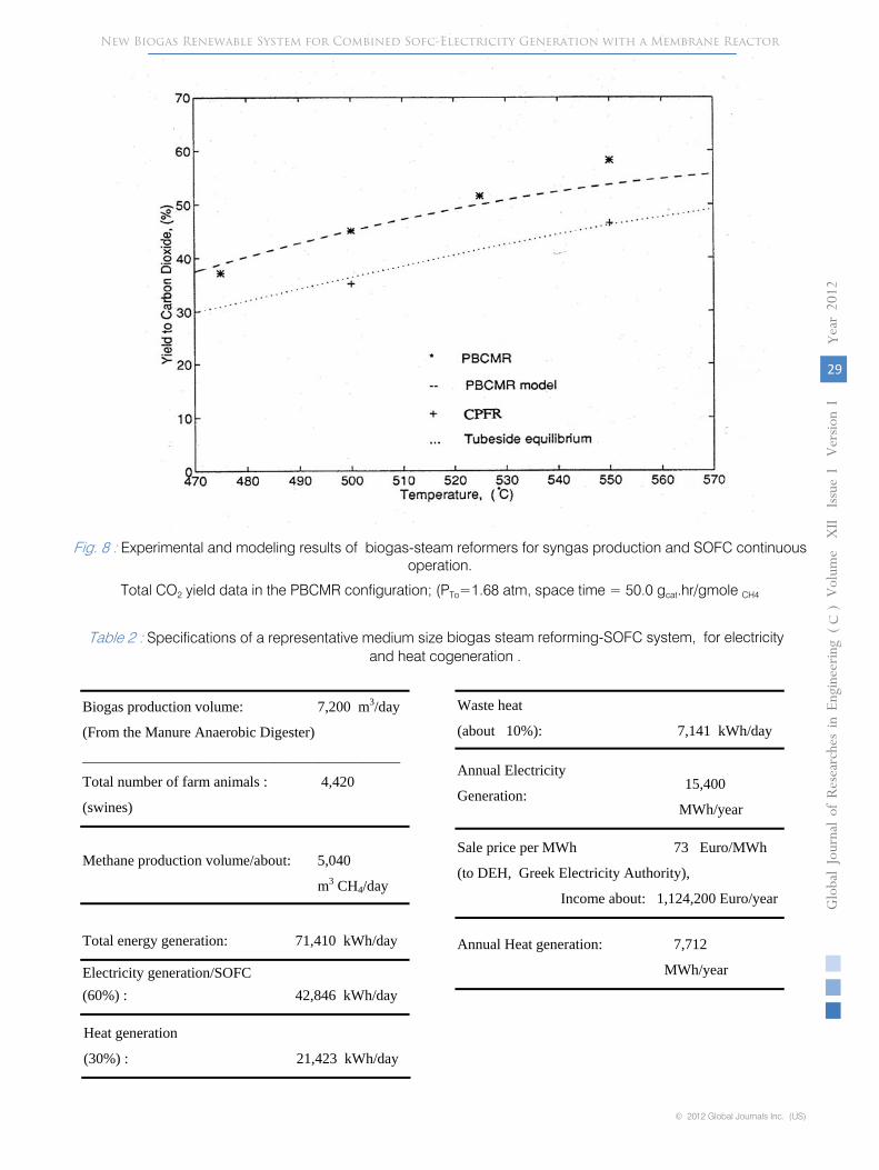
Fig. 8 : Experimental and modeling results of biogas-steam reformers for syngas production and SOFC continuous operation.
New Biogas Renewable System for Combined Sofc-Electricity Generation with a Membrane Reactor
Table 2 : Specifications of a representative medium size biogas steam reforming-SOFC system, for electricity and heat cogeneration .
Biogas production volume: 7,200 m3/day
(From the Manure Anaerobic Digester)___________________________________________
Total number of farm animals : 4,420
(swines)
Methane production volume/about: 5,040
m3 CH4/day
Total energy generation: 71,410 kWh/day
Electricity generation/SOFC (60%) : 42,846 kWh/day
Heat generation
(30%) : 21,423 kWh/day
Waste heat
(about 10%): 7,141 kWh/day
Annual Electricity
Generation: 15,400
MWh/year
Sale price per MWh 73 Euro/MWh
(to DEH, Greek Electricity Authority),
Income about: 1,124,200 Euro/year
Annual Heat generation: 7,712
MWh/year
Globa
l Jo
urna
l of R
esea
rche
s in E
nginee
ring
Volum
e X
II Issue
vvvvI
Versio
n I
29
(DDDD
)c
© 2012 Global Journals Inc. (US)
ea
r 20
12
Y
Total CO2 yield data in the PBCMR configuration; (PTo=1.68 atm, space time = 50.0 gcat.hr/gmole CH4

This page is intentionally left blank
New Biogas Renewable System for Combined Sofc-Electricity Generation with a Membrane ReactorGloba
l Jo
urna
l of R
esea
rche
s in E
nginee
ring
Volum
e X
II Issue
vv v I V
e rsio
n I
30
(DDDD
)c
© 2012 Global Journals Inc. (US)
ea
r 20
12
Y