Embed Size (px)
Citation preview

New Advances in CT Dosimetry
John M. Boone, Ph.D., FAAPM, FSBI, FACR
Professor and Vice Chairman of RadiologyProfessor of Biomedical EngineeringUniversity of California, Davis
Chairman, AAPM Science Council
Chairman, ICRU committee on CT Image Quality and Patient Dosimetry

New Advances in CT Dosimetry
IntroductionCTDI100
-based metricsImage Quality and CT Dosimetry PhantomCT Dose versus Scan LengthCorrection for Patient SizeCT Scanner OutputSummary
ICRU perspectives
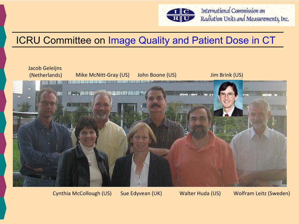
ICRU Committee on Image Quality and Patient Dose in CT
Jacob Geleijns(Netherlands) Mike McNitt‐Gray (US) John Boone (US)
Walter Huda (US)Cynthia McCollough (US) Sue Edyvean
(UK) Wolfram Leitz
(Sweden)
Jim Brink (US)

Use of CT: USA & UC Davis Trends
Boone, J M et al J Am Col Radiology, 2008;5(2): 132–138Brenner, D J et New Eng J Med, 2007;357: 2277-2284
1990: Helical CT
1998: Multi-Slice CT

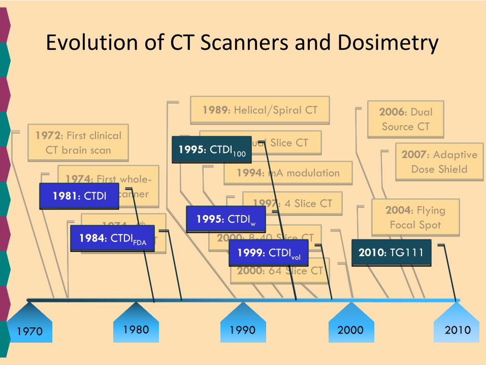
Evolution of CT Scanners and Dosimetry
19901970 1980 2000 2010
1994: mA
modulation1994: mA
modulation
2006: Dual Source CT
2006: Dual Source CT
1989: Helical/Spiral CT1989: Helical/Spiral CT
1972: First clinical CT brain scan 1972: First clinical
CT brain scan
1974: 4th
generation CT
1974: 4th
generation CT
1974: First whole-
body CT scanner 1974: First whole-
body CT scanner
1992: Dual Slice CT1992: Dual Slice CT
1997: 4 Slice CT1997: 4 Slice CT
2000: 8-40 Slice CT2000: 8-40 Slice CT
2000: 64 Slice CT2000: 64 Slice CT
2007: Adaptive Dose Shield
2007: Adaptive Dose Shield
2004: Flying Focal Spot
2004: Flying Focal Spot
1981: CTDI1981: CTDI
1984: CTDIFDA
1984: CTDIFDA
1995: CTDI100
1995: CTDI100
1995: CTDIw
1995: CTDIw
1999: CTDIvol
1999: CTDIvol 2010: TG1112010: TG111

New Advances in CT Dosimetry
IntroductionCTDI100
-based metricsImage Quality and CT Dosimetry PhantomCT Dose versus Scan LengthCorrection for Patient SizeCT Scanner OutputSummary
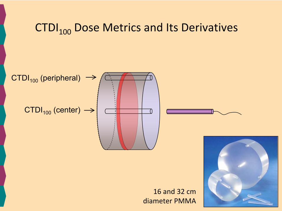
CTDI100
(peripheral)
CTDI100
Dose Metrics and Its Derivatives
CTDI100
(center)
16 and 32 cm diameter PMMA

CTDIw
= 1/3 CTDI100,center
+ 2/3 CTDI100,periphery
CTDIvol
= CTDIw
/ pitch
Dose Length Product (DLP) = L × CTDIvol
Effective Dose ≈
DLP ×
k
scan location k
Head
Chest
Body
Abd-Pelvis
Pelvis
0.0023
0.017
0.015
0.017
0.019

32 cm
ρ
= 1.19
47”
119 cmwaistline
28 cm≈
CTDIvol

New Advances in CT Dosimetry
IntroductionCTDI100
-based metricsImage Quality and CT Dosimetry PhantomCT Dose versus Scan LengthCorrection for Patient SizeCT Scanner OutputSummary
Monte Carlo modeling is the most accurate
method for determining organ doses in CT IntroductionCTDI100
-based metricsImage Quality and CT Dosimetry PhantomCT Dose versus Scan LengthCorrection for Patient SizeCT Scanner OutputSummary
Proposed methods are designed to support and promote MC methods, and to facilitate the integration of MC‐based dosimetry
into clinical patient CT dosimetry

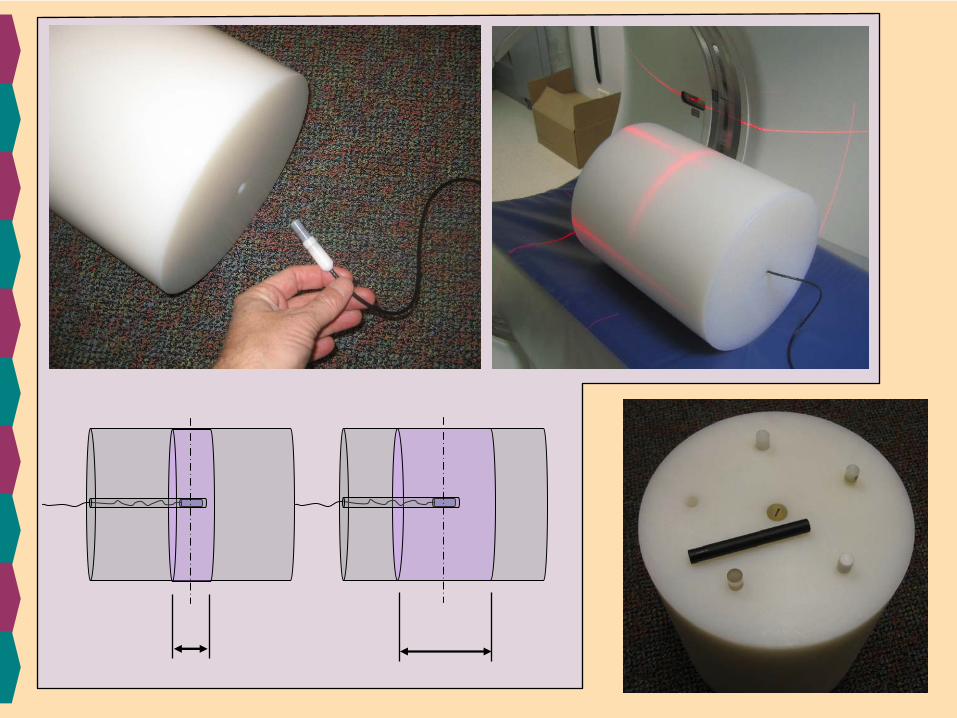
ICRU CT phantom
spatialresolution
dosimetry
contrast resolution
contrast

polyethylene phantom30 cm diameter30 cm length~14 kg
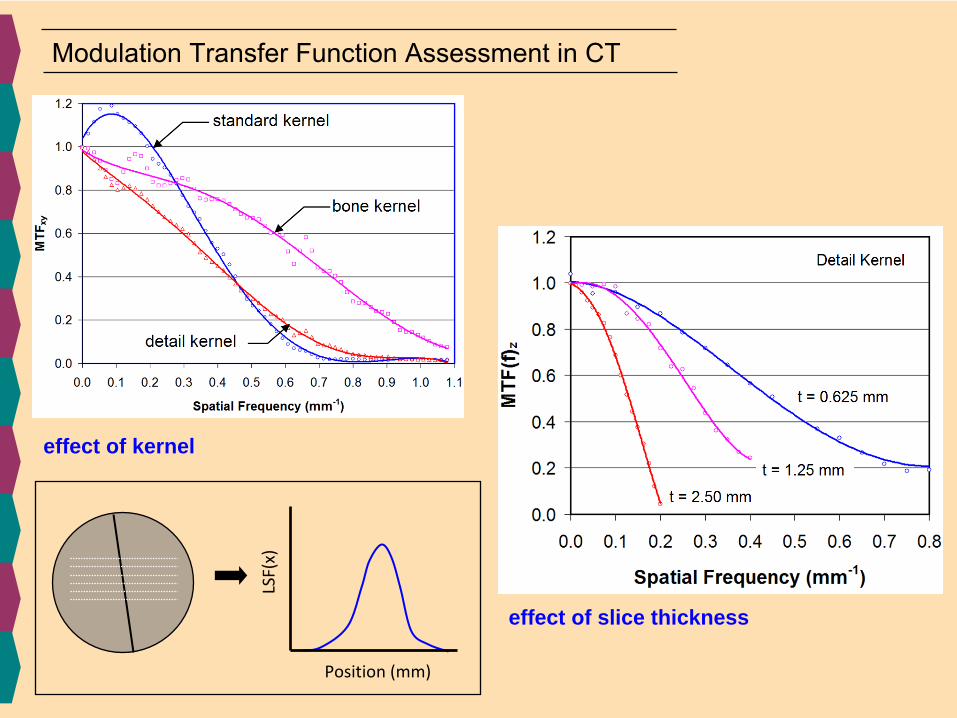
Modulation Transfer Function Assessment in CT
effect of kernel
effect of slice thickness
LSF(x)
Position (mm)

Noise Assessment
noise power spectrum (NPS)
120 kVp200 mA, 0.5 s, 100 mAsPitch = 1.0
13.33 mGy
120 kVp200 mA, 0.5 s, 150 mAsPitch = 1.0
20.0 mGy
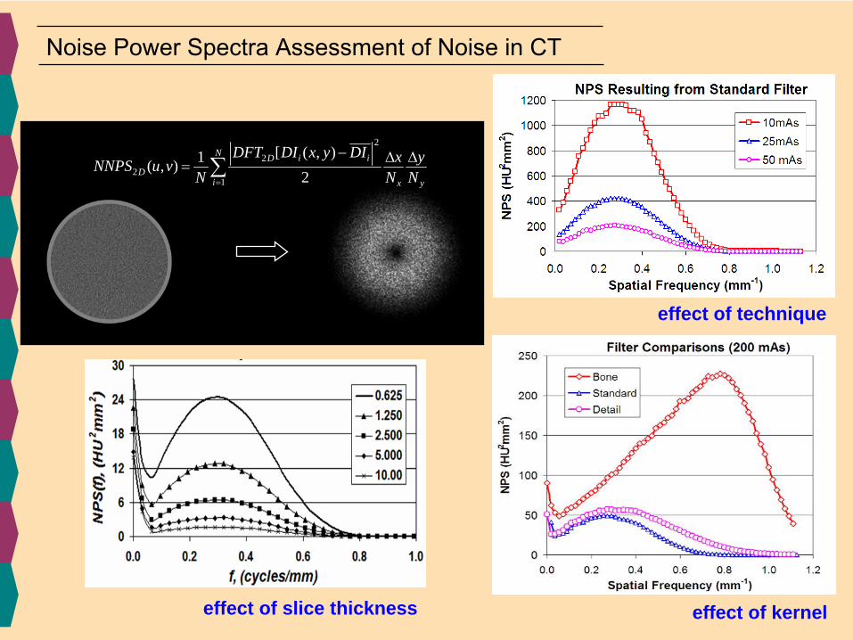
Noise Power Spectra Assessment of Noise in CT
effect of technique
effect of kerneleffect of slice thickness
2
22
1
[ ( , )1( , )2
N i iDD
i x y
DFT DI x y DI x yNNPS u vN N N=
− Δ Δ= ∑
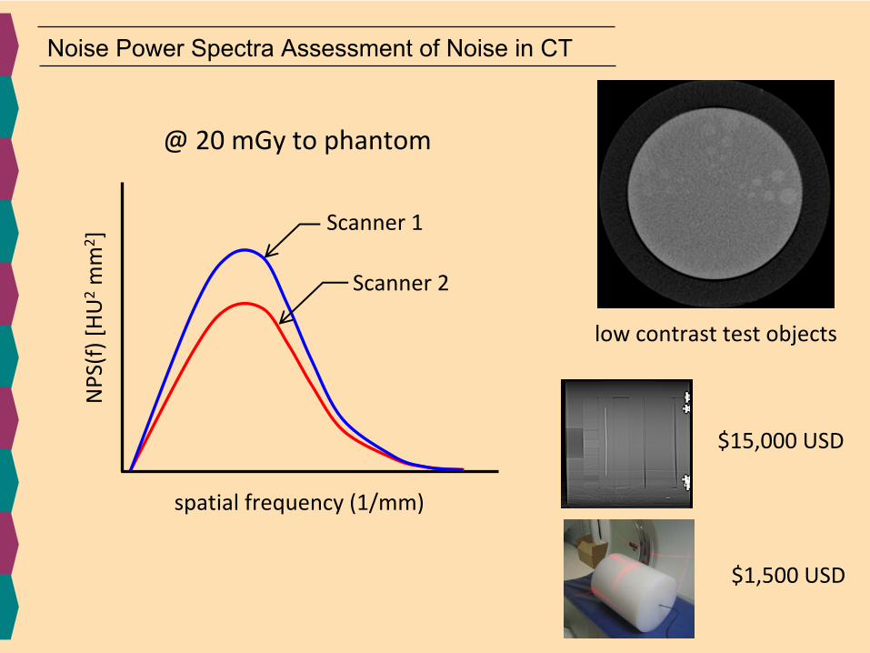
spatial frequency (1/mm)
NPS(f) [HU2mm
2 ]
@ 20 mGy to phantom
Scanner 1
Scanner 2
low contrast test objects
$15,000 USD
$1,500 USD
Noise Power Spectra Assessment of Noise in CT

CT image quality evaluationOld Era New Era
phantom
analysis
results
simple more sophisticated
2( )( )
( )
ifxLSF x e dxMTF f
LSF x dx
π∞
−
−∞∞
−∞
=∫
∫
complicated basic
useful & quantitativeperfunctory

New Advances in CT Dosimetry
IntroductionCTDI100
-based metricsImage Quality and CT Dosimetry PhantomCT Dose versus Scan LengthCorrection for Patient SizeCT Scanner OutputSummary
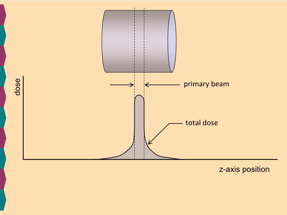
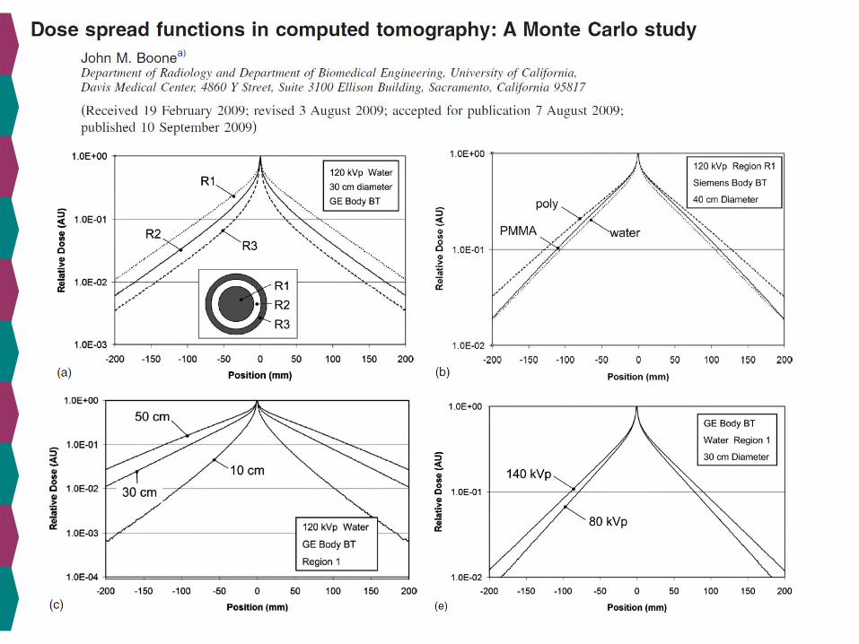
dose
z-axis position
primary beam
total dose

total dose
dose
z-axis position
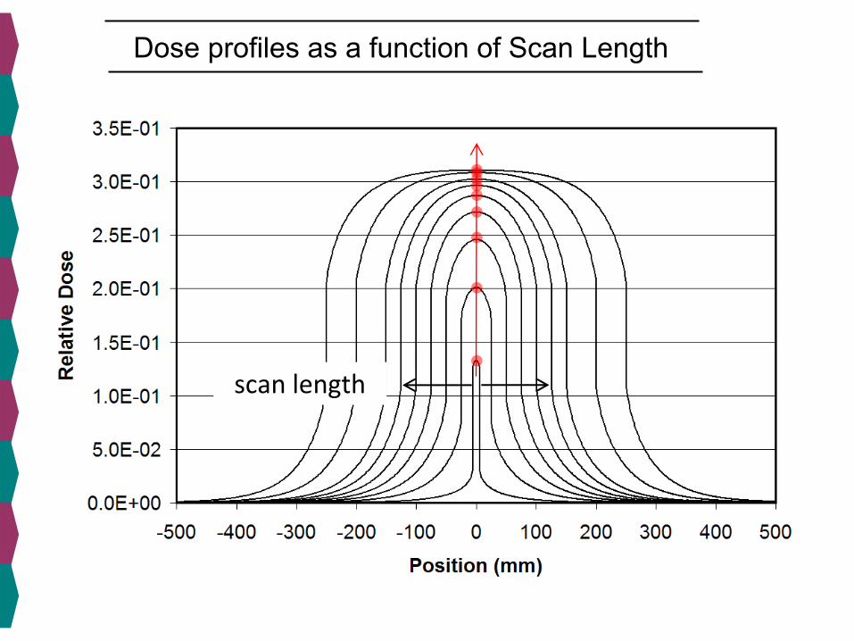
Dose profiles as a function of Scan Length
scan length

Equilibrium Dose as a function of Scan Length
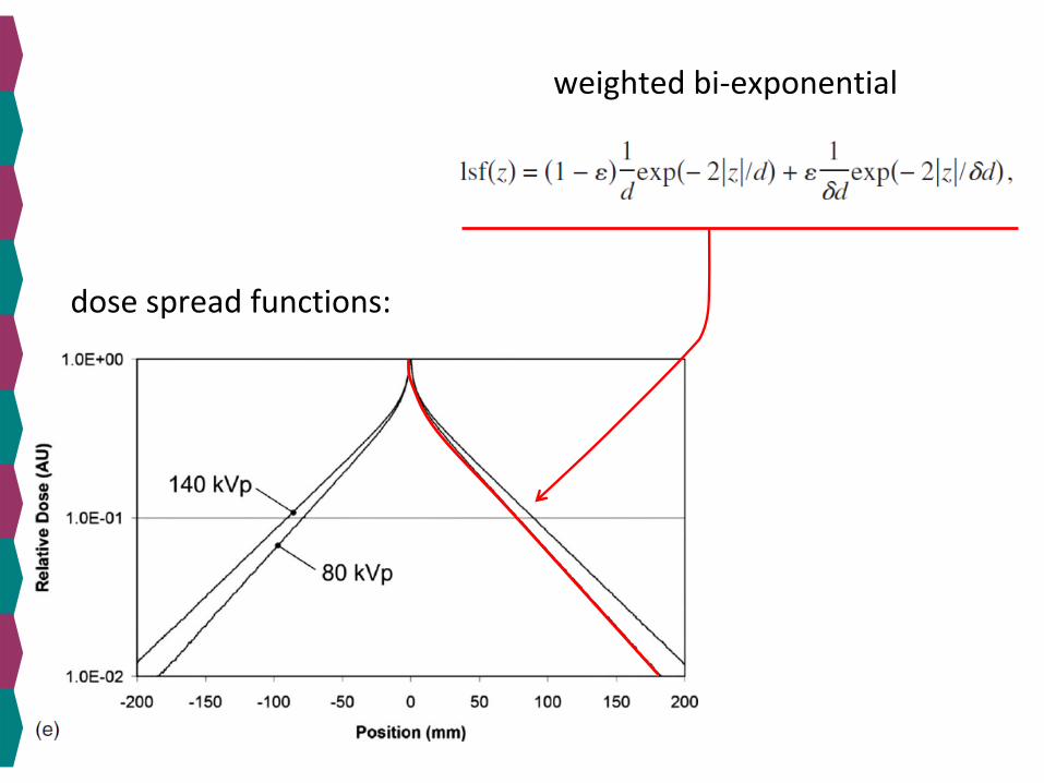
weighted bi‐exponential
dose spread functions:
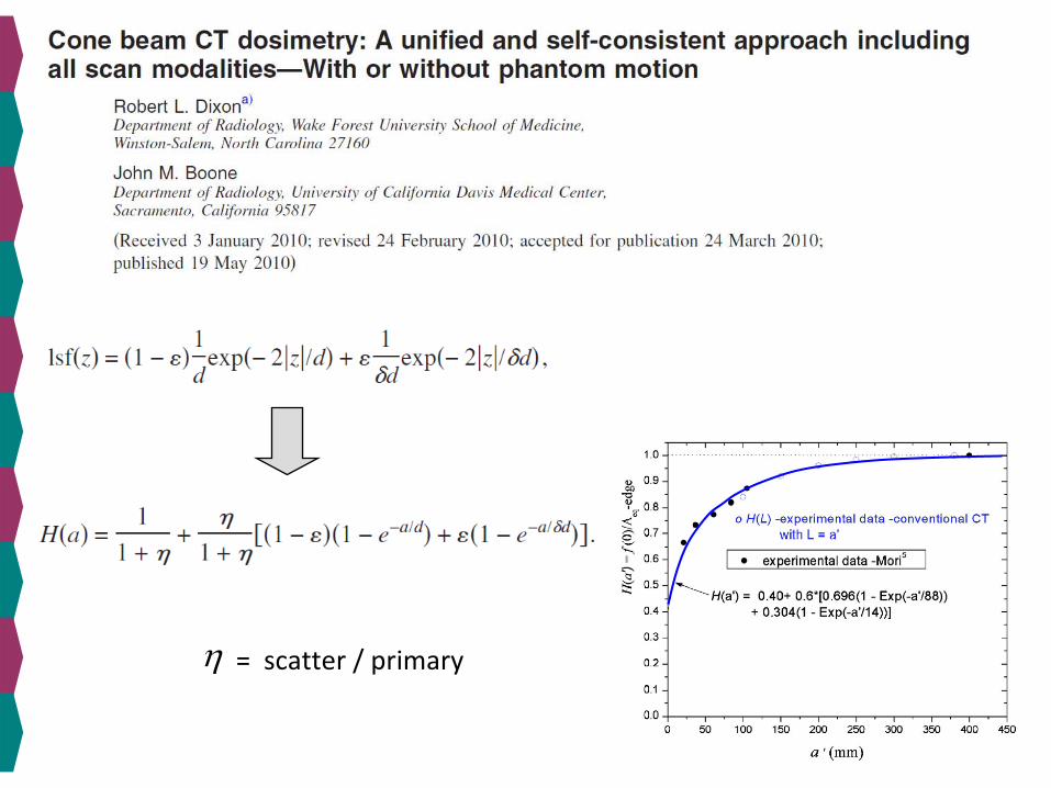
η = scatter / primary

Gd2
O2
S scintillator
fiber optic bundle
photodiode
electronics
Real Time X‐ray Probe
time
volta
ge

ICRU Method
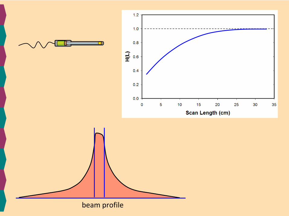
beam profile

Correction
Factor

New Advances in CT Dosimetry
IntroductionCTDI100
-based metricsImage Quality and CT Dosimetry PhantomCT Dose versus Scan LengthCorrection for Patient SizeCT Scanner OutputSummary

effective diameter
Relativ
e do
se
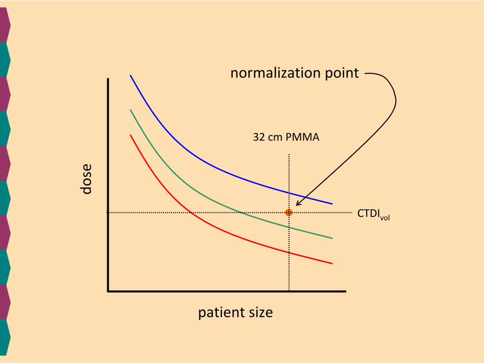
patient size
dose
CTDIvol
32 cm PMMA
normalization point

correctio
n factor
CTDIvol
32 cm
after normalization
1.0
patient size
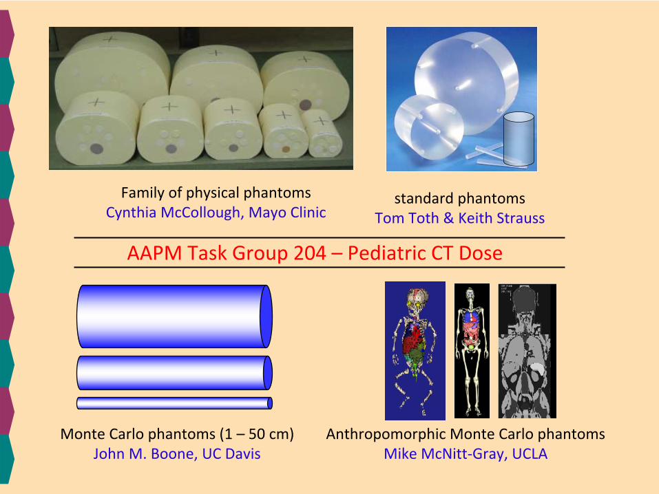
Family of physical phantomsCynthia McCollough, Mayo Clinic
standard phantomsTom Toth & Keith Strauss
Monte Carlo phantoms (1 – 50 cm)John M. Boone, UC Davis
Anthropomorphic Monte Carlo phantomsMike McNitt‐Gray, UCLA
AAPM Task Group 204 –
Pediatric CT Dose

120 kVp
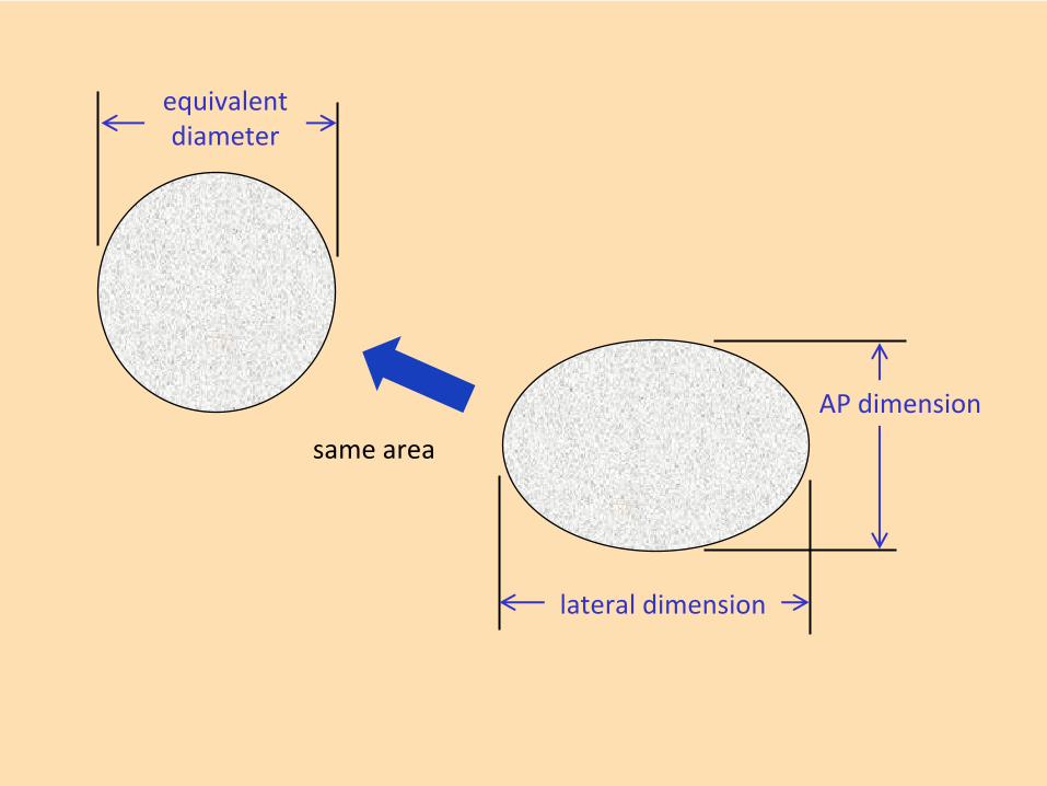
lateral dimension
AP dimension
equivalentdiameter
same area
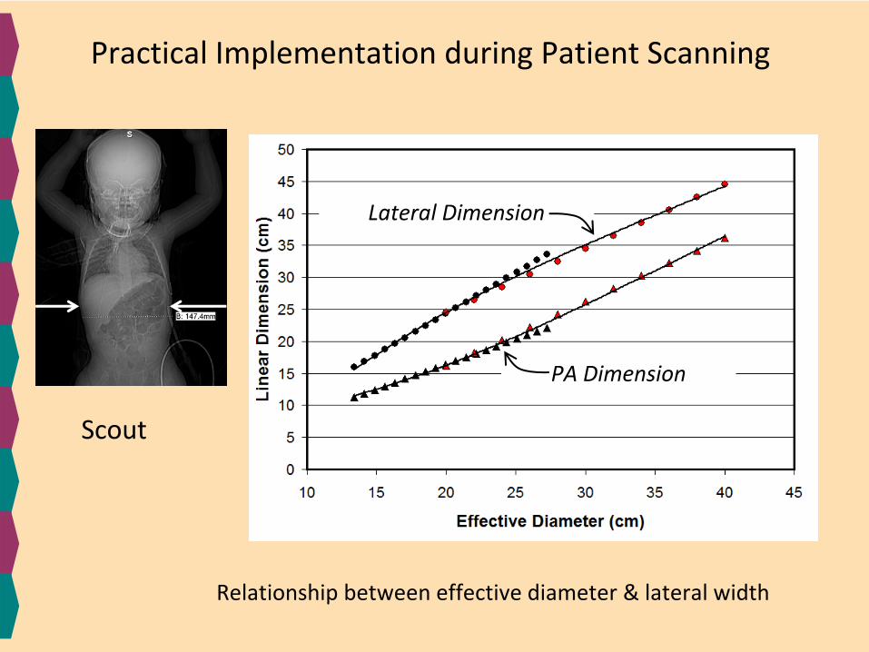
Scout
Practical Implementation during Patient Scanning
Relationship between effective diameter & lateral width
Lateral Dimension
PA Dimension

Dose Index value (CTDIvol
) is on most scanners…..
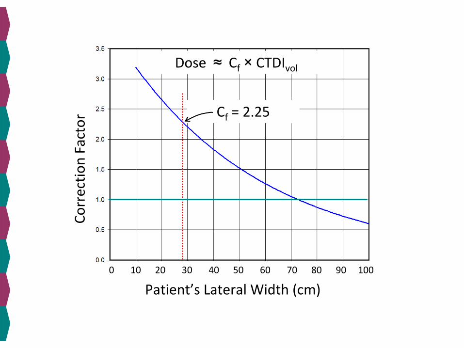
Correctio
n Factor
Patient’s Lateral Width (cm)0 10 20 30 40 50 60 70
80 90 100
Dose ≈
Cf
×
CTDIvol
Cf
= 2.25
New Advances in CT Dosimetry
IntroductionCTDI100
-based metricsImage Quality and CT Dosimetry PhantomCT Dose versus Scan LengthCorrection for Patient SizeCT Scanner OutputSummary

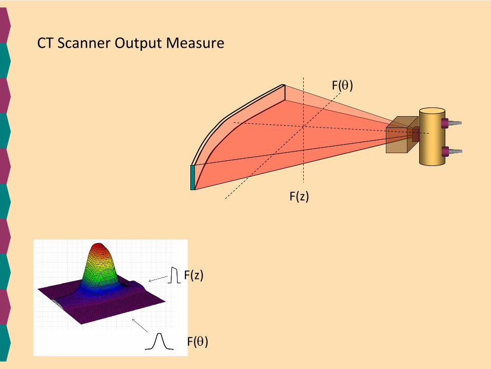
F(θ)
F(z)
CT Scanner Output Measures along z‐axis
Influence of beam width / collimation / penumbra

dose
z-axis position
CT Scanner Output Measures
(in phantom with scatter tails)

32 cm diameter • 15 cm long14.3 kg •
31.6 pounds
16 cm diameter • 15 cm long3.6 kg • 7.8 pounds
proposed ICRU phantoms30 cm long
25 cm dia14.0 kg
30.8 pounds
30 cm dia20.1 kg
44.3 pounds
30 cm dia10 kg
22.2 pounds
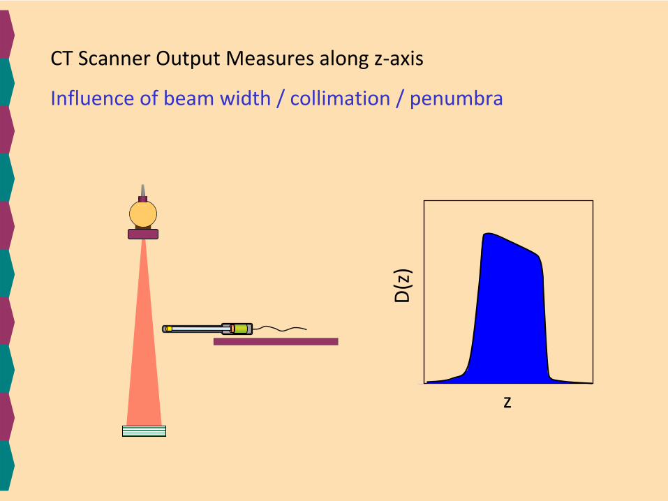
D(z)
z
CT Scanner Output Measures along z‐axis
Influence of beam width / collimation / penumbra

dose
(z)
CT Scanner Output Measures
z
with phantom
in air
QC / QA recommendations acceptance testing
acceptance testing& periodically
z
F(θ)
F(z)
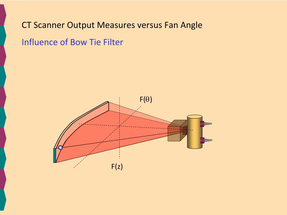
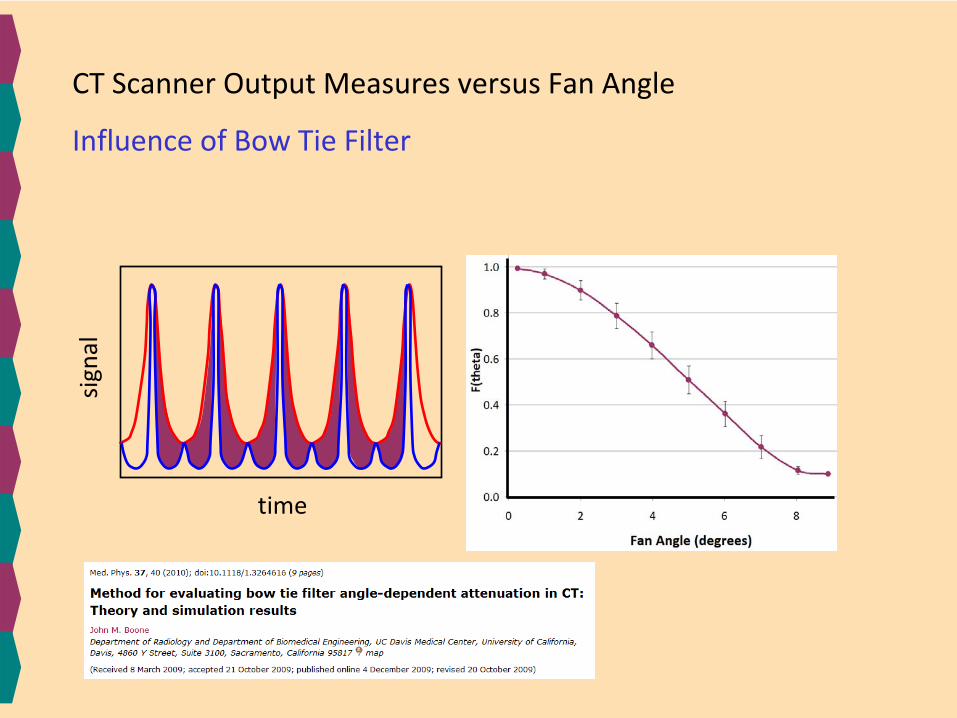
CT Scanner Output Measures versus Fan Angle
Influence of Bow Tie Filter

time
signal
CT Scanner Output Measures versus Fan Angle
Influence of Bow Tie Filter
time
signal
CT Scanner Output Measures versus Fan Angle
Influence of Bow Tie Filter
F(θ)
F(z)
F(θ)
F(z)
CT Scanner Output Measure

New Advances in CT Dosimetry
IntroductionCTDI100
-based metricsImage Quality and CT Dosimetry PhantomCT Dose versus Scan LengthCorrection for Patient SizeCT Scanner OutputSummary

organ dosesCT scan & patient parameters
Monte Carlo modeling should be
the basis for patient CT dosimetry
Monte Carlo
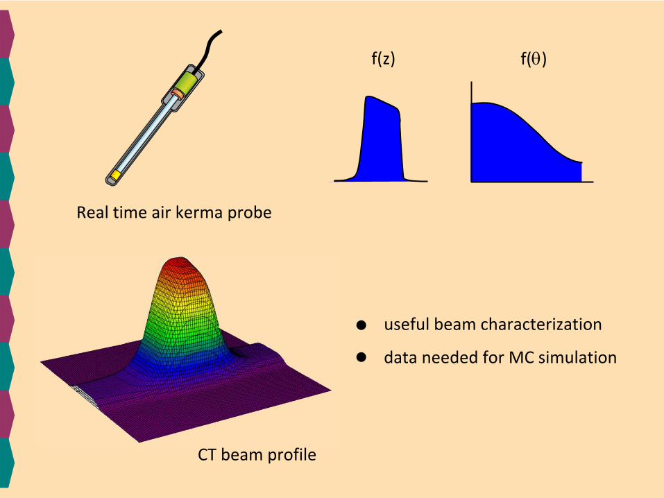
Real time air kerma probe
CT beam profile
f(z) f(θ)
useful beam characterization
data needed for MC simulation
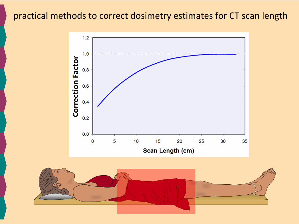
practical methods to correct dosimetry estimates for CT scan length
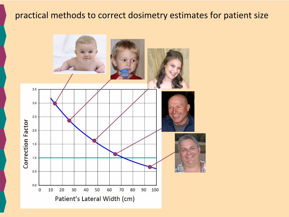
practical methods to correct dosimetry estimates for patient size
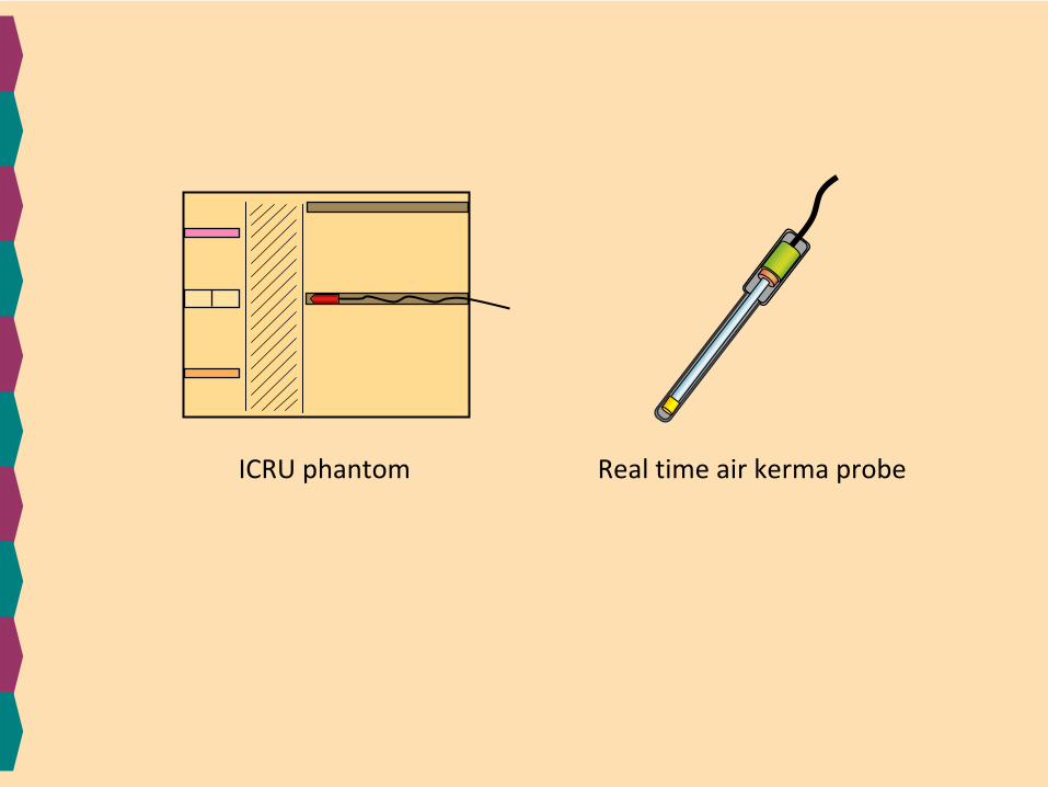
ICRU phantom Real time air kerma probe
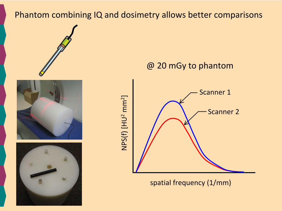
spatial frequency (1/mm)
NPS(f) [HU2mm
2 ]
@ 20 mGy to phantom
Scanner 1
Scanner 2
Phantom combining IQ and dosimetry allows better comparisons

New Advances in CT Dosimetry
IntroductionCTDI100
-based metricsImage Quality and CT Dosimetry PhantomCT Dose versus Scan LengthCorrection for Patient SizeCT Scanner OutputSummary


![Radiation dosimetry in CT: the role of the manufacturer · Radiation dosimetry in CT: the role of the manufacturer PERSPECTIVE the CTDI vol on current CT scanners [21,101]. The liver](https://img.pdfslide.us/doc/110x75/5fa0fb2e14d1e9179a40de08/radiation-dosimetry-in-ct-the-role-of-the-manufacturer-radiation-dosimetry-in-ct.jpg)