Embed Size (px)
Citation preview
NOV. 191932 NEW 59 TUBE 15c
Per Copy
REG. U.S. PAT. OFF.
The First and Only National Radio Weekly
Eleventh Year 556th Year
How to Make a Simple
Tangent Galvanometer
What IntermediateFrequency Is Best?
I The ALL-WAVE DRAGONP-224 2t.tis DETECTOR TUBE
PRE -SELECTOR TRIMMER
F TRIMMER
P- 247 POWER TUBE
P-280 RECTIFIER TUBE
POWER TRANSFORMER
VOLUME CONTROL
ON -OFF SWITCt-I
WAVE -BAND SELECTOR
IF SEC. TRIMMERIF PRI. TRIMMER
2No. 1. F TRAN5FORMERP-235 L F. TUBE
F SEC, TRIMMERPRLTRIMMER
PRE-5ELECTOR COIL
3T. I. F TRANSFORMER
DETECTOR TRIMMER
P- 2 35 B.C7 R F TUBE
P-224 I sr DETECTOR TUBE
B.C. DETECTOR COIL
B, C OSC I L L ATOR COIL
P-227 OSCILLATOR TUBE
View of the Pilot Dragon. See Detailed Article Beginning on Page 10.
STROMBERG - CARLSON CIRCUITS

RADIO WORLD November 19, 1932
PADDING CONDENSERS
700.1.000 mmfd. (Cat.710) 55 50e net.
350-450 mmfd. (Cat.3545) a 50e net.
AHIGH-CLASS padding condenser is required for asuperheterodyne's oscillator, one that will hold itscapacity setting and will not introduce losses in the
circuit, for losses create frequency instability. TheHammarlund padding condensers are of single -condenserconstruction on Isolantite base, with set -screw easily ac-
pc- cessible, and non -stripping thread. For 175 kc. intermediatefrequency use the 700-1,000 mmfd. model.. For i.-f. fromPo"460 to 365 kc., use the 350-450 mmfd. (General Motors models).
0.0005 HAMMARLUND S. F. L. at 98cA sturdy, precision straight frequency line condenser, with end stops.The removable shaft protrudes front and rear and permits ganging withcoupling device, also use of clockwise or anti -clockwise dials, or twoeither side of drum dial. Front panel and chassis -top mounting facilities.True straight line. This rugged condenser has Hanamariund's highquality workmanship and is suitable for precision work. It is a mostexcellent condenser for calibrated radio frequency test oscillators, any fre-quency region, 100 to 60,000 kc., short-wave converters and adaptersand TRF or Superheterodyne broadcast receivers. Lowest loss construc-tion, rigidity; Hammarlund's perfection throughout.Order Cat. H05 @ 98c net
Guaranty Radio Goods Co., 143 West 45th Street, New York, N. Y.
RADIO AND OTHERTECHNICAL BOOKS
At a Glance"The Electric Word," by Shubert 2.50
"Elements of Radio Communication," byMorecroft 3.00
"Experimental Radio," by Ramsey 2.75
"Foothold on Radio," by Anderson andBernard 1.00
"Fundamentals of Radio," by Ramsey 3.50
"Mathematics of Radio," by Rider 2.00"Practical Radio," by Moyer & Wastrel 2.50
"Practical Radio Construction and Repairing,by Moyer & Wostrel 2.50
"Principles of Radio," by Henney 3.50"Principles of Radio Communication," by
Morecroft 7.50"Absolute Measurements in Electricity and
Magnetism," by Gray 14.50"The Radio Manual," by Sterling"Radio Receiving Tubes," by Moyer &Wastrel 2.50
"Radio Telegraphy & Telephony," by Duncan 7.50"Radio Trouble Shooting," by Haan 3.00"The Superheterodyne," by Anderson &Bernard 1.50
TELEVISION"A B C of Television," by Yates 3.00
AUTOMOBILES"Ford Model 'A' Car and 'AA' Truck, new edi-tion, by Maj. Page 2.50
AVIATION"A B C of Aviation," by Maj. Page 1.00"Aerial Navigation and Meteorology," by Capt.
Yancy 4.00"Everybody's Aviation Guide," by Maj. Page 4.00"Modern Aircraft," by Maj. Page 5.00"Modern Aviation Engines," by Maj. Page 9.00
RADIO WORLD145 West 45th Street
New York, N. Y.
Your Choice of NINE Meters!To do your radio work properly you need me-
ters. Here is your opportunity to get them at noextra cost. See the list of nine meters below.Heretofore we have offered the choice of any oneof these meters free with an 8 -weeks' subscriptionfor RADIO WORLD, at $1, the regular price forsuch subscription. Now we extend this offer.For the first time you are permitted to obtainany one or more or all of these meters free, bysending in $1 for 8 -weeks' subscription, entitlingyou to one meter; $2 for 16 weeks, entitling youto two meters; $3 for 26 weeks, $6 for 52 weeks,entitling you to six meters. Return coupon withremittance, and check off desired meters insquares below.
RADIO WORLD. 145 West 4511 snot, New York. N. Y.(Just Soot of Sreadaroy)
Enclosed please fled $ for weekssubscription for RADIO WORLD and please mead as frupremium the meters shacked off below.
0 I am a subscriber, 11Usd my subserint`u. (Cheekoff If true.)o 0-0 Voltmeter D.O. No. 321CI 0.50 Voltmeter 0.0o 0 -Volt Charge Tester D.0 No. 11O 1-10 Amperes D.C. No. 334O 0-25 511111am D.O. No. 320I:3 5-50 PAIlllemperes D.C. Ns. 315o 0-100 MIlllarri D.O. No. $50CI 0-300 511111ani D.O. No. 315In 0-405 MIllls 13.0 No. 354
NAME
ADDRESS
CITY STATE
SOLDERING IRONF R E EWorks on 110-120 volts AC or DC, power,50 watts. A serviceable iron, with coppertip, 5 ft. cable and male plug. Send $1.50for 13 weeks' subscription for Radio Worldand get these free! Please state if you arerenewing existing subscription.
RADIO WORLD145 West 45th St. N. Y. City
Two for theprice of One
Get, EXTRA, one-year subscription for any One of these magazines:Q.S.T. (monthly, 12 issues; official amateur organ).POPULAR SCIENCE MONTHLY.RADIO -CRAFT (monthly, 12 issues).RADIO INDEX (monthly, 12 issues), stations, programs, etc.RADIO (monthly, 12 issues; exclusively trade magazine).EVERYDAY SCIENCE AND MECHANICS (monthly).RADIO LOG AND LORE. Bi-monthly; 5 issues. Full station lists, cress indexed, etc.AMERICAN BOY -YOUTH'S COMPANION (monthly, 12 issues; popular magazine).BOYS' LIFE (monthly, 12 issues; popular magazine).OPEN ROAD FOR BOYS (monthly, 12 issues).Select any one of these magazines and get it free for an entire year by sending in a year's sub-scription for RADIO WORLD at the regular price, $6.00. Cash in now on this opportunity to getRADIO WORLD WEEKLY, 52 weeks at the standard price for such subscription, plus a full year'ssubscription for any ONE of the other enumerated magazines FREE. Put a cross in the square nextto the magazine of your choice, in the above list, fill out the coupon below, and mail $6 check,money order or stamps to RADIO WORLD, 145 West 45th Street, New York, N. Y. (Add $1.50, making$7.50 in all, for extra foreign or Canadian postage for both publications.)
Your Name
Your Street Address
City State0 If renewing an existing or expiring subscription for RADIO WORLD, please put a cross in squareat beginning of this sentence.0 If renewing an existing or expiring subscription for other magazines, please put a cross in squareat the beginning of this sentence.RADIO WORLD, 145 West 45th Street, New York. (Just East of Broadway)
DOUBLEVALUE!
SAVE YOUR TUBES!Protect against coil and tube burn out, short circuit andflue hazards due to antenna circuit becoming groundedthrough fallen or crossed aerials.
THE SILENT WATCHMANShould Bo Used on Every Electric Radio
FREDRICK'S SAFETY PROTECTOR, $1.50, prepaid mall.Time tested and fully guaranteed.
P. R. FREDRICK'S RADIO STUDIO345 W. 23rd St. (Tel. CH elsea 3-1144) New York City
,Located on same block nearly 10 years)
RIDER'S PERPETUALTROUBLE SHOOTER'S
MANUALVol. 1 and Vol. 2
Having assembled 2,000 diagrams of com-mercial receivers, power amplifiers, con-verters, etc., in 1,200 pages of Volume No.1 of his Perpetual Trouble Shooter's Manual,John F. Rider, noted radio engineer, hasprepared Volume No. 2 on an even moredetailed scale, covering all the latest re-ceivers. Volume No. 2 does not duplicatediagrams in Volume No. 1, but containsonly new, additional diagrams, and a newall-inclusive information on the circuitscovered.Volume No. 2 -Perpetual Trouble Shooter's
Manual, by John F. Rider. Shippingweight II lbs. Order Cat. RM-VT t $5.1111
Volume No. 1 (5 lbs.). Order Cat. RM-VO$4.55
We pay postage in United States on re-ceipt of purchase price with order. Canadian,Mexican and other foreign remittances mustbe in funds payable in New York.
RADIO WORLD145 WEST 45th ST., NEW YORK, N. Y.
115 DIAGRAMS FREE115 Urals Diagrams at Commercial seesiveri usePower Supplies supplementing the diagrams is John P.lider's "Trouble Shooter's Manual." These schematadiagrams of factory -made resolvers, Using the mane -runner's name and model Number op oath diagram, laelude the MOST IMPORTANT SCRILIN GRID 11-CEITIRS.The 115 diagrams, each is black and whits, en @buts0', 11 inches, punched with three standard holes teeloose-leaf binding, constitute s supplement that mast beobtained by all possessors of "Trouble Shooter's Manual,"to make the manual complete. We guarantee es duplieadon of the diagrams that appear in the "Manual."Cireulti include Bosch 54 D. siren grid; BsikiteModel P, Crosloy 10, 21. 21 series grid; lvereadY eerie'II acreen grid; iris 124 A. C. screen grid; Purism!lean:static series; Philco TO ruses grid.Subscribe for Radio World for 1 mouths as the routs,subscription rate of Ill 50, and have these diagrams de-livered I. you TRIllProssatt subseribsto sway kit foolvontoso of Muafar. PIO 0.TO rut a cress lure 0 to osOoditoo.rtendilso your osfrirotioss date.Radio World, 145 West 45th St., New York, N. Y.
Quick -ActionClassified
Advertisements7c a Word - $1.00 Minmium
Cash With Order77 MILES ON 1 GALLON! Car owners save10% to 50% by using our gas saver. Agentsprofit 266%. One free. Scientific Gas Saver,B 160 St. Wheaton, Illinois.
BARGAINS IN FINEST PARTS! - Highestgrade, new parts, few of each on hand. Nationaldial, flat type, modernistic escutcheon, type G,clockwise, $2.19; Pilot drum dial No. 1285 @ $1.89;a -c toggle switch, 19c; triple pole, four -throwBest switch, insulated shaft, $1.62; double pole,four throw, $1.08. Direct Radio Co., 145 West45th St., N. Y. City.THE FORD MODEL -"A" Car and Model "AA"Truck -Construction, Operation and Repair -Re-vised New Edition. Ford Car authority. VictorW. Page. 708 pages, 318 illustrations. Price $2.50.Radio World, 145 W. 45th St., New York."THE CHEVROLET SIX CAR AND TRUCK"(Construction -Operation -Repair) by Victor W.Page, author of "Modern Gasoline Automobile,""Ford Model A Car and AA Truck," etc., etc.450 pages, price $2.00. Radio World, 145 W. 45thSt., N. Y. City.
THE FIVE NEW TUBES, 46, 56. 57, 58 and 82,characteristics, installation data, uses, fully de-scribed and illustrated in the April 30th issue (7pages) and in the May 7th issue. Send 30c forthese two copies. Radio World 145 West 45thStreet, New York, N. Y.
OFFICERS: Roland BurkeHennessy, President a a AiTreasurer; M. B. Hennessy.Vice -President; HermanBernard, Seeretae,-
ROLAND BURKE HENNESSYEditor
HERMAN BERNARDManaging Editor
The First and Only National Radio WeeklyELEVENTH YEAR
J. E. ANDERSONTechnical Editor
J. MURRAY BARRONAdvertising Manager
Vol. XXXII NOVEMBER 19, 1932 No. 10, Whole No. 556Published weekly by Hennessy Radio Publications Corporation, 145 West 45th Street, New York, N. Y.
Editorial and Executive Offices : 145 West 45th Street, New YorkTelephone: BR-yant 9.0558
Entered as second-class matter March, 1922, at the Post Office at NewYork, N. Y., under Act of March 3, 1879. Title registered in U. S.Patent Office. Printed in the United States of America. We do notassume any responsibility for unsolicited manuscripts, photographs,drawings, etc., although we are careful with them.
Price, 15c per Copy; $6.00 perYear by maiL $1.00 extraper year in foreign countries.Subscribers' change of addressbecomes effective two weeksafter receipt of notice.
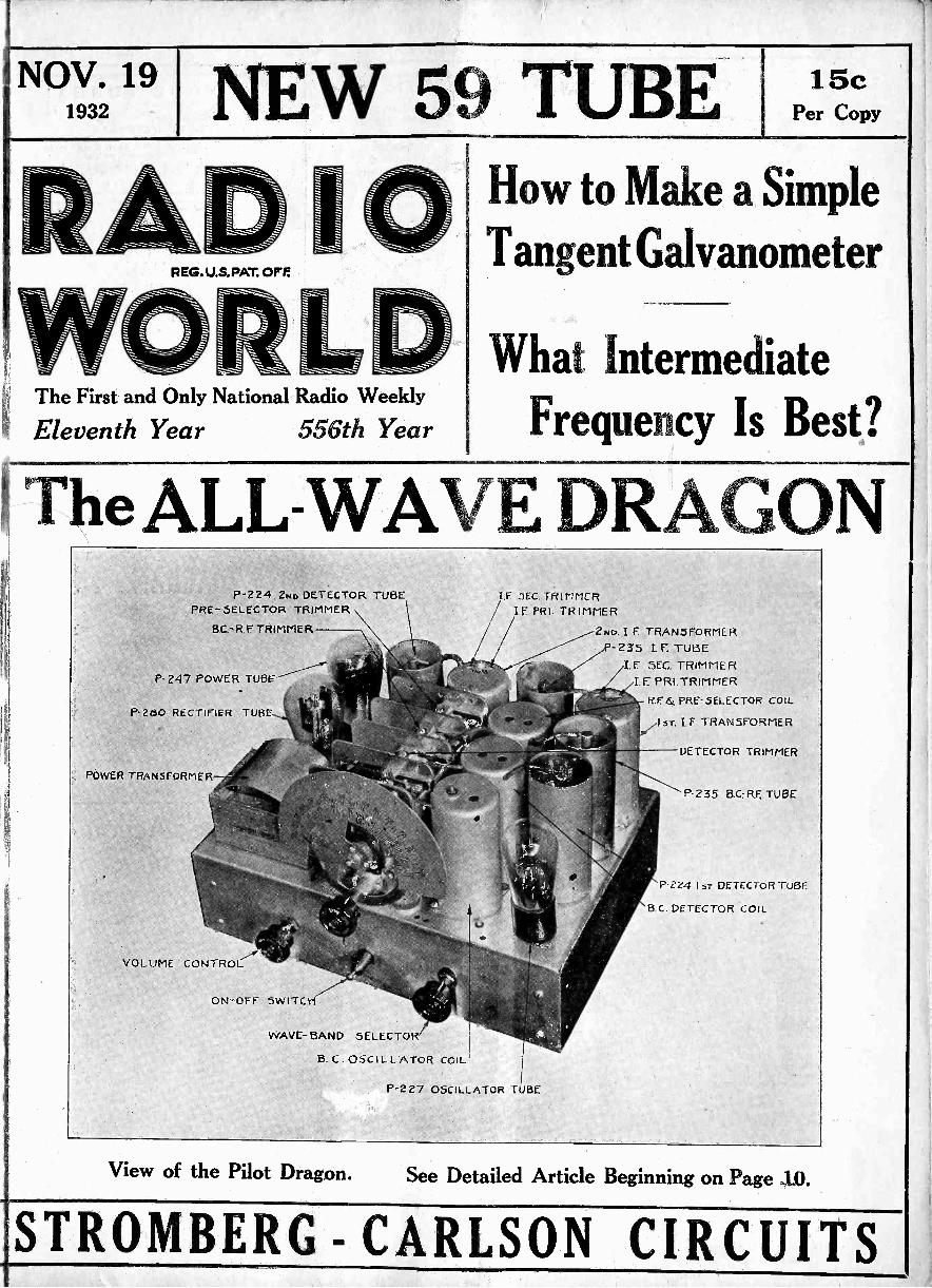
FULL DATAON NEW 59 TUBE
Output Valve Has Heater and IndependentCathode
The following is the contents of "Pre-liminary Technical Information on the NewTriple -Grid Power Amplifier Tube, Unipo-tential Cathode Type, RCA -59, CunninghamC-59," and is published by permission ofthe two companies.
THE 59 is a triple -grid power ampli-fier tube of the heater -cathode typerecommended for use in the output
stage of a -c operated receivers. Thetriple -grid construction of this tube, withexternal connections for each grid, makespossible its application as
(1) a Class A Power Amplifier Triode,(2) a Class A Power Amplifier Pentode,
and(3) a Class B Power Amplifier Triode.The three -fold application of the 59 to
audio power -amplifier circuits is accom-plished by different connections of thethree grids incorporated in the tube'sstructure. Thus, one arrangement of gridelectrodes provides a triode for Class Aservice with a relatively low amplificationfactor, a low plate resistance, and a highmutual conductance; while another pro-vides a triode with an amplification factorso high that negative grid bias is not re-quired for its operation as a Class Bpower amplifier. A pair of 59's so con-nected in a Class B output stage is cap-able of supplying an exceptionally largeamount of power ; while a single 59 oper-ated in the driver stage as a Class A am-plifier, will deliver sufficient power to drivethe pair of 59's in the output stage. Athird arrangement of the grids makes pos-sible the use of the 59 as a Class A poweroutput pentode capable of delivering alarge amount of power with relativelysmall signal vpltage input.
The heater -cathode construction em-ployed in the 59 is another step forward inobtaining uniformly low hum -level inhigh quality power amplifier design. Theadvantages to be gained by the use ofheater -cathode tubes in the power outputstage cannot, of course, be realized unlessall preceding stages are coordinated indesign to the same high quality per-formance.
In appearance, the 59 is characterized
by the dome -top bulb, the rugged elec-trode assembly, and the 7 -pin base toprovide terminals for each electrode.
Class A vs. Class B AmplificationIn Class A service the grid of the tube
is maintained negative with respect to thecathode by an amount such that someplate current flows at all times, and suchthat the grid takes no appreciable cur-rent during the most positive swing ofthe signal voltage. These operating con-ditions are obtained when the normal biaswithout signal gives sufficient operatingplate current to permit the application ofa peak signal having twice the bias valuewithout reducing the plate current belowa certain predetermined minimum valueunder the load conditions employed, orwithout swinging the grid positive. Thus,the value of grid signal voltage whichcan be applied to any given type of tubeis limited and this results in limited poweroutput. Theoretically, the maximum platecircuit efficiency for Class A operation is50%, assuming a sine wave input signal.The actual plate circuit efficiencies, how-ever, are of the order of 20% for triodesand 40% for pentodes.
Distinguishing features of this class ofservice are that no appreciable power isrequired by the grid and that essentiallyundistorted power output may be ob-tained either with a single tube or withtwo tubes in a push-pull circuit, the latterbeing the nearest approach to distortion -less amplification known. However, com-paratively low power output is obtained atlow efficiency. Furthermore, rated platecurrent is required from the power supplyregardless of whether or not signal vol-tage is applied to the grid.
In Class B service the tube is operatedso that the plate current is practicallyzero with no grid excitation. When asignal of sufficient magnitude is appliedto the grid, there will be no plate cur-rent flow over a substantial part of thenegative excursions of the signal voltage.A considerable amount of second andhigher even -ordered harmonic distortionis thus introduced into the power output
of a single tube. However, with two tubesin a balanced push-pull circuit, the evenharmonics are eliminated from the poweroutput. In such a circuit, therefore, twotubes may be employed as Class B am -output.
Class B Service
In Class B service it is possible to drivethe grids of the two amplifier tubes posi-tive to a certain amount and still obtainreasonably undistorted output, providedthat sufficient input power is available tosupply the grid current required by thepositive grids. This power is convenientlysupplied by a Class A power amplifierfeeding the grids of the output tubesthrough a push-pull transformer havingproper characteristics. Usually this trans-former has a step-down ratio.
By designing Class B amplifier tubeswith a sufficiently high mufactor, it ispossible to operate them with zero gridbias, and so dispense with biasing resis-tors whose effect would be to produceconsiderable loss in sensitivity because ofdegenerative effects. Since provision torgrid bias is unnecessary with such tubes,the entire voltage of the rectifier is avail-able for plate supply.
Distinguishing features of this class ofservice are that very high output of goodquality may be obtained with fairly smalltubes operating at relatively low plate vol-tage; and that unusual overall economy ofpower consumption is possible becausethe plate current is very low when nosignal is applied to the grid. To givethese adYi:ntages, the Class B amplifiercircuit requires the use of two tubes in abalanced output stage preceded by adriver stage capable of supplying consid-erable undistorted power and the use of apower supply capable of maintaining goodvoltage regulation regardless of the va-riation of average plate current with sig-nal intensity. It should be noted that thedistortion present in the high power out-put of Class B amplifiers is usually neg-ligible but is always somewhat higher for
(Continued on next page)
4 RADIO WORLD November 19, 1932
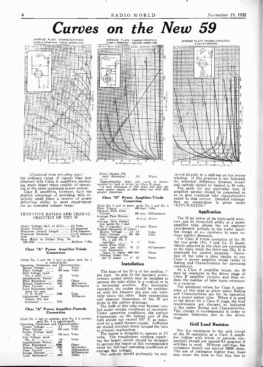
Curves on the New 59AVERAGE PLATE CHARACTERISTICS
' CLASS A OPERATION -TRIODE CONNECTION
E f =2.5 -R-;t .
;:-;
ki
elPLATE M1aIL LIAMPERES
2 °
(Continued from preceding page)the ordinary range of signals than thatobtained with Class A amplifiers employ-ing much larger tubes capable of operat-ing at the same maximum power output.
Class B amplifiers, however, have thedistinct advantage of providing with re-latively small tubes a reserve of powerdelivering ability to meet requirementfor art extended volume range.
TENTATIVE RATING AND CHARAC-TERISTICS OF THE 59
Heater CurrentMaximum Overall LengthMaximum DiameterBulbBase (Refer to Outline Dwg. No.
92S-4196) Medium 7 -Pin
Heater Voltage (A.C. or D.C.) 2.5 Volts2 0 Amperes5 3.8 Amperes21-16 AmperesST -16
Class "A" Power Amplifier -TriodeConnection
(Grids No. 2 and No. 3 tied to plate; grid No. 1is control -grid)
Operating Conditions and Characteristics:Heater Voltage 2.5 VoltsPlate Voltage 250 max. VoltsGrid Voltage (grid
No. 1 only) -28 VoltsAmplification Factor 6.0Plate Resistance 2400 OhmsMutual Conductance 2600 MicromhosPlate Current 26 MilliamperesLoad Resistance (opti-
mum for max.U. P. 0.),A,* 5000 Volts
Undistorted Power MilliwattsOutput (5% 2ndharmonic) 1250
Class "A" Power Amplifier -PentodeConnection
(Grid No. 3 tied to cathode; grid No. 2 is screen;grid No. 1 is control -grid)
Operating Conditions and Characteristics:Heater Voltage 2.5 VoltsPlate Voltage 250 max. VoltsScreen Voltage (grid
No. 2) 250 max. VoltsGrid Voltage (grid
No. 1) -18 VoltsAmplification Factor 100Plate Resistance 40000 OhmsMutual Conductance 2500 MicromhosPlate Current 35 MilliamperesScreen Current 9 MilliamperesLoad Resistance* 6000 Ohms
AVERAGE PLATE CHARACTERISTICSCLASS A OPERATION - PENTODE CONNECTION
111.11E.
mEdEEEEMEMEEUEMIEEEREBI Epignimmiimma:giiimaiNEE EEE" T;;EIFEWEEEEN
....AIREEEEN;MEE. KIIMIfflWilEEEMEffl
111EMEEEEINEEEli
AESEEMEEEP:....11MEEERAM E
MEEMEEPE1111111EIRE1MIIIINEEZ
7.411EREMEIE42.EELIMESEIER
4.1EEMENEEElliP
WAVERVINUOINIP ;41posinmaimall*.z.LEEEKEWEIlli. :tiogaftrillikERMENA
. .
=WU
8
SCREEN VOLTS .250
PLATE MILLIAMPERES(1b)
Power Output (7%total distortion) .. 3.0 Watts
0
0
9
*Approximately twice this value is recom-mended for load of driver for Class B stage.
*A load resistance of 7000 ohms will give thesame power output as 6000 ohms but with 20%greater distortion.
Class "B" Power Amplifier -TriodeConnection
(Grid No. 3 tied to plate; grids No. 2 andPlate Voltage 400 max. VoltsDynamic Peak Plate
CurrentAverage Plate Dissipa-
tion 10 max. WattsAverage Grid Dissipa-
tion (grids No. 1 andNo. 2 together) 1.5 max. Watts
Typical Operation (2 tubes):Heater Voltage ... 2.5 2.5Plate Voltage 300 400Grid Voltage (grids
No. 1 and No. 2together) 0 0
Static Plate (Cur-rent (per tube) 10 13
Load Resistance(plate to plate) 4600 6000
Nominal Power Out-put (2 tubes) 15 20
Installation
No. 1
200 max. Milliamperes
VoltsVolts
Volts
Milliamperes
Ohms
Watts
The base of the 59 is of the medium 7 -pin type. Its pins fit the standard seven -contact socket which may be installed tooperate the tube either in a vertical or ina horizontal position. For horizontaloperation, the socket should be position-ed with the filament pin pins one verti-cally above the other. Base connectionsand external dimensions of the 59 aregiven in the outline drawings.
The bulb of this tube may become veryhot under certain conditions of operation.Under operating conditions, the surfacetemperature on the hottest part of thebulb should not exceed 150° F. as meas-ured by a small thermo-copule. Sufficientair should circulate freely around the tubeto prevent overheating.
The heater is designed to operate at 2.5volts. The transformer winding supply-ing the heater circuit should be designedto operate the heater at this recommendedvalue for full -load operating conditions ataverage line voltage.
The cathode should preferably be con -
0
AVERAGE PLATE CHARACTERISTICSCLASS B OPERATION
2.5 VOLTS
I3 -C PLATE OR D -C GRID M L- LIAMPERES(Ib OR lc!)
nected directly to a mid -tap on the heaterwinding. If this practice is not followed,the potential difference between heaterand cathode should be limited to 45 volts.
The grids for any particular type ofamplifier service should be connected soas to give resultant tube characteristicssuited to that service. Detailed informa-tion on connections is given under"APPLICATION."
ApplicationThe 59 by virtue of its triple -grid struc-
ture and its three -fold utility as a poweramplifier tube, allows the set engineerconsiderable latitude in the 'audio ampli-fier design of a -c receivers to meet va-rious market demands.
For Class A triode operation of the 59,the two grids (No. 3 and No. 2) imme-diately adjacent to the plate are connectedto the plate, while the third one (No. 1) isemployed for control purposes. Opera-tion of the tube is then similar to anyClass A power amplifier triode (refer toRating and Characteristics for operatingconditions).
As a Class A amplifier triode, the 59may be employed in the driver stage ofClass B amplifier circuits, and thus re-duce the number of tube types necessaryin a receiver.
The tabulated values for Class A oper-ation of this type as given under Ratingand Characteristics are for its operationas a power output tube. When it is usedas the driver for a Class B stage, the loadrequirements are changed as indicatedin the under Rating and Characteristics.This change is recommended in order tominimize distortion due to the driverstage.
Grid Load ResistorThe d -c resistance in the grid circuit
of the 59 operating as a Class A ampli-fier (either with triode or _pentode con-nection) should not exceed 0.5 megohm ifself -bias is used. Without self -bias, theresistance should not exceed 10000 ohms.The use of resistance higher than thesemay cause the tube to lose bias due to

November 19, 1932
grid current with the result that the platecurrent will rise to a value sufficientlyhigh to damage the tube.
For Class A Pentode operation of the59, the grid (No. 3) adjacent to the plateis tied to the cathode and thus serves asthe suppressor, while the other two grids(No. 2 and No. 1) serve as the screen -grid and control -grid respectively. Oper-ation of the tube is then similar to anyClass A power output pentode (refer toRating and Characteristics for operatingconditions).
For Class B triode operation of the 59,the grid (No. 3) adjacent to the plate istied to the plate, while the other two grids(No. 2 and No. 1) are connected togetherto serve as a single control -grid. No gridbias is necessary with this connection.This feature is particularly important be-cause it prevents the variation of bias withapplied signal which would otherwise existif any self -bias arrangement were em-ployed.
Grid Circuit PowerDuring operation of this tube as a Class
B amplifier, the interconnected grids No.1 and No. 2 are swung positive each halfcycle. Considerable power is required todo this under ordinary conditions. If,however, the secondary emissivity of thegrids were made nearly equal to unity,the required power to swing the gridscould be appreciably decreased. Tubespossessing this feature have been con-structed, but the secondary emissivity isnot independent of signal voltage and fre-quently causes negative grid current. Fur.thermore, secondary emission behaves er-ratically during the life of the tube. Thus,to have a Class B tube which will giveuniform results throughout its life, it ispreferable from the tube design stand-point, as in the case of the 59 with ClassB connections, to eliminate secondaryemission insofar as possible even at theexpense of greater driving power. Unlesstubes for use as Class B amplifiers arecapable of producing uniform resultsthroughout their life, it is practically im-possible to design circuits to use them.
Power from Driver StageThe direct current requirements of
Class B circuits are subject to fluctuationunder operating conditions. The powersupply, therefore, should have as goodregulation as possible to maintain properoperating voltages regardless of the cur-rent drain. For thN purpose, a suitablydesigned B -eliminator may be employed.A rectifier tube of the mercury-vaportype is recommended because it has alow and practically constant space -charge -voltage drop within its operatinglimitations. As a further means of ob-taining good regulation, the filter chokesand transformer windings of the B -elim-inator should have as low resistance aspossible. In the design of a power supplyfor a Class B amplifier, consideration
RADIO WORLD 5
should be given to the peak current de-mand of the amplifier.
As previously pointed out, the grid (No.1 and No. 2) of the 59 is operated suf-ficiently positive to cause grid current toflow in its input circuit. This feature im-poses a further requirement on the pre-ceding amplifier stage. It must supplynot only the necessary input voltage, butit must be capable of doing so under con-ditions where appreciable power is takenby the grid of the Class B amplifier tube.Since the power necessary to swing thegrid positive is partially dependent on theplate load of the Class B tube, and sincethe efficiency of power transfer from thepreceding stage is dependent on trans-former design, it is apparent that the de-sign of a Class B audio power amplifierrequires that more than ordinary atten-tion be given to the effects produced bythe component parts of the circuit. Theseeffects may be produced in the first -stageamplifier by the design factors of thepower -output stage. For this reason, thedesign of a Class B audio amplifier withits driver stage is somewhat more involvedthan for a Class A system, and must bechecked for each change in the com-ponent parts.
A complete discussion of design featuresfor Class B amplifier would be rather ex-tensive, but certain outstanding pointsmay be mentioned. The interstage trans-former is the link interconnecting thedriver and the Class B stage. It is usuallyof the step-down type, that is, the primaryinput voltage is higher than the secondaryvoltage supplied to the grids of the poweroutput tubes. Depending upon conditions,the ratio of the primary of the interstagetransformer to one-half its secondarymay range between 1.5/1 and 5.5/1.
The transformer step-down ratio is de-pendent on the following factors :-
1. Type of driver tube2. Type of power tube3. Load on power tube4. Permissible distortion5. Transformer efficiency (peak power)
Practical Non -Reactance
The primary impedance of the inter -stage transformer should be essentiallythe same as if the transformer were to beoperated with no load, that is, into anopen grid. Since power is transferred, thetransformer should have reasonable powerefficiency. It should be noted that thepower output and distortion are often crit-ically dependent upon the circuit con-stants which should, therefore, be madeas near independent of frequency as pos-sible. This applies particularly to the in-terstage coupling transformer and to theloudspeaker. Since it is difficult to com-pensate for leakage reactance of thecoupling transformer without excessiveloss of h -f response, the leakage reactanceof this transformer should be as low aspossible.
The type of driver tube chosen should
be capable of handling sufficient powerto operate the Class B amplifier stage.Allowance should be made for trans-former efficiency. It is most important,if low distortion is desired, that the drive'rtube be worked into a load resistancehigher than the normal value for optimumpower output as a Class A power ampli-fier, since distortion produced by thedriver stage _and the power stage will bepresent in the output.
The following notes on Class B Ampli-fier circuits are of value from the designstandpoint :-
The load on the driver tube or tubes ischosen higher than for undistorted powerrating to hold overall distortion to aminimum. For a single triode driver, itsminimum plate load should be approxi-mately 2 to 4 times the plate resistance ofthe driver tube. For a push -null triodedriver stage, its minimum plate load pertube should be approximately equal tothe plate resistance of an individual tube.This ratio for push-pull operation is per-missible principally because of eliminationof second harmonic distoition. This mini-mum plate load is the value used for cal-culating peak power transformer effi-ciency.
An interstage transformer with highstep-down ratio causes low distortion inthe Class B input circuit, but limits theavailable signal. A satisfactory trans-former design makes use of grid distor-tion to cancel a part of the distortion pro-duced in the plate circuit of a Class Bstage. For this reason, the transformerstep-down ratio must not be too great.Resistance losses of the primary and ec-ondary may be diitribiited on the basis ofthe most economical design. It is impor-tant to consider that only one-half of thesecondary furnishes power at a time.
The load values for the Class B ampli-fier stage given under Rating and Charac-teristics will change slightly with avail-able input if maximum output and lowdistortion are desired. It is important toconsider that only one-half of the primaryof the output transformer furnishes powerat one time.
Tube List PricesType
ListPrice Type
ListPrice
Type PriceList
11 $3.00 '32 2.35 57 1.6512 3.00 '33 2.80 58 1.65112-A 1.55 '34 2.80 59 2.50'20 300 '35 1.65 1.05'71-A 05 2.80 '81 5.20UV -'99 2.75 37 1.80 82 1.30UX-'99 2.55 '38 2.80 83 1.55'100-A 4.00 '39 2.80 '74 4.90'01-A .80 ,40
3.00 '76 6.70'10 725 '45 1.15 '41 10.40'22 3.15 46 1.55 ,68 7.50'24-A 1.65 47 1.60 ,64 2.10'26 .85 48 2.80 tsg 28.00'27 1.05 '50 6.20 '65 15.00'30 1.65 55 1.60 '66 10.50'31 1.65 56 1.30
In Preparation! Radio Woriers Holiday Issue!ROCKEFELLER CENTER NUMBER
(Including RADIO CITY)Progress and Development of
Vorld's Greatest Commercial and Amusement Achievement
RADIO WORLD November 19, 1932
STROMBERG-CARLSON'SLATEST CIRCUITS
44 AR
F658
/.6 58 TU458RF AMPLIFIER
I
5e. TUBEMIXER
600'7'
1
SA. OOI MP 7-
-YAW65004/4, 6300//'
vISOAL 44A31145META
56 TUBE.OSCILLATOR
513 TUBE.I.F. gMPUF1E'.t
MIL
56 TUBEDEMODuLATOR A -V. C
TAD 71JBC.1St A4910
.PILOT LAMP
4S TUBESAUDIO OUTPUT
80 71.19CPCT in ER
1.0
4
SPEAKER 5/ELO2.000s.-
4ME4408'.
170".'
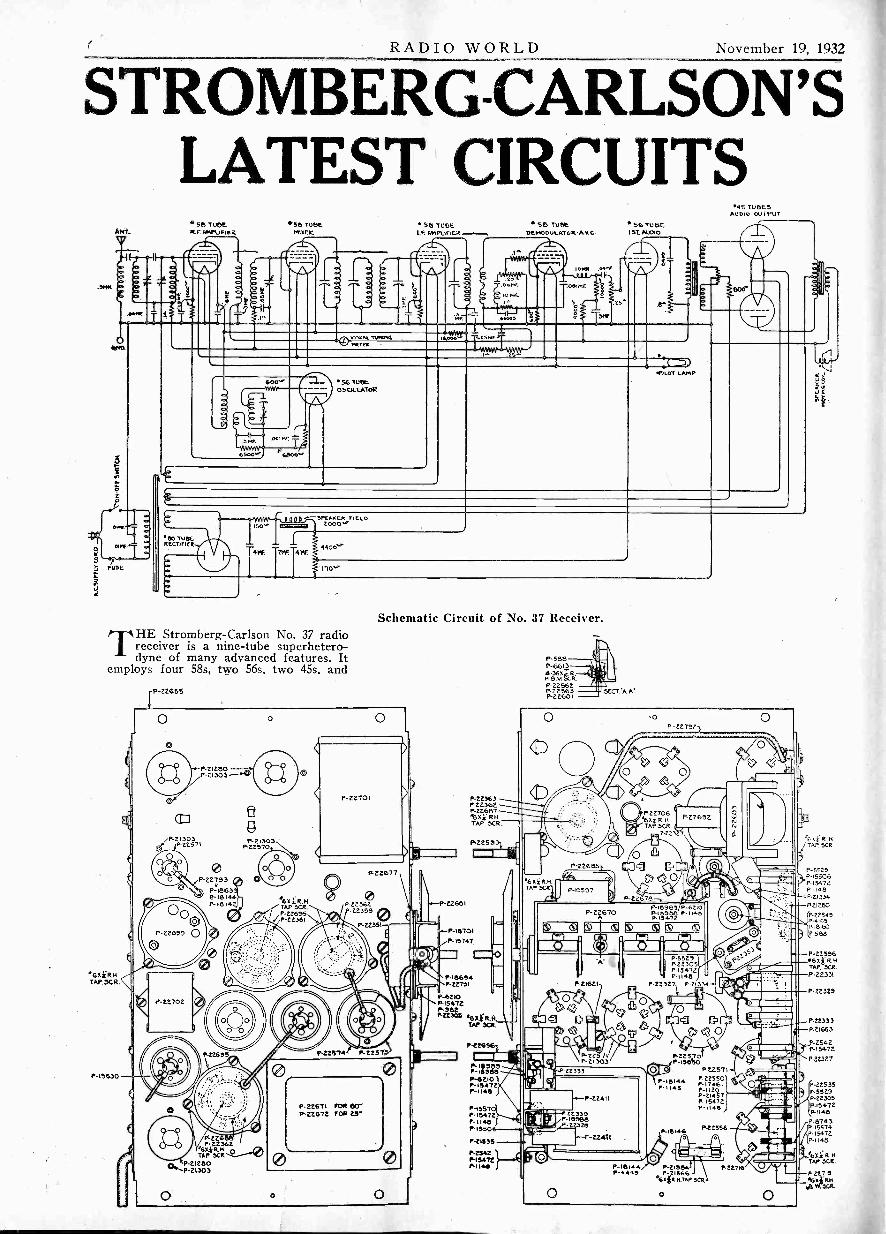
Schematic Circuit of No. 37 Receiver.THE Stromberg-Carlson No. 37 radio
receiver is a nine -tube superhetero-dyne of many advanced features. It
employs four 58s, two 56s, two 45s. and
.6X;R.HTAP.CR
P-15630
i-P-22656
P.212130P -Z1303 --NR
P-22793
P-18639P-18144P- 18142
P- 2270 2
0-41172.2.`
P-21303P22570
'1T1''11P-22695P-22361
0P 22362.
2.2355 0
P -22351-4-
P 225/4 14..
P22677
P.22363P223R-2p-22687
R HTAP 3CR.
PL22553
A-P-22661
P-18701
P -t5747
P-11365P.22751
p--6210P-15472
rz-eitz, 6Xilt.H,TAP 3CR.
P-226
MM.PilUeP-6210P-15472P-,1415
P-155-70IA 15478
1148P - I5
P-21535
142542P-15472P-1146
P-588P-66134364ER
Ft_.1.1
P -2256ZP.22563p-zzeot
3
SECT..A. A.
O
T6 4}RKTAP SCR
P-2266
P- 2 £670
22782-i
O
9,..,z7.6SRP223
A
O
P22692
P -I59/33 P-67108-1/35013 P-117,
5472
ts)
P. 21 62 I
P-22 71P 21303
22333
P.224 II
78330P-18888
ze
-22411
WO a ha
P.5521 IP.22305P 15472P 1148
P 22327 P21314
P-16144P-4449
P-18144P -I145
Q 0
P 22550P-17461P-1123P-21457A 15472P-1145,
1522556
P-2155414,2156E.
61111 4.44P SCR
O
P22716
O
(z3
ALA-'
WO
WE48 FT.
U K.TAP SCR
2-5525P-155068.15472P.1148P 21334
821280
P-22545P-
6,16,11,58.8
P-22556x 1.R H
TAP. 3CR8.22331
P 22323
P-22333821653
P-2542P-15471
P 22327
P-22535P.5525P-22305P13472AI148
P-8743i5514
P.15472p.I145
.65114TAP SCR.
P 12

November 19, 1932 RADIO WORLDone '80. The output tubes are Class Apush-pull.
The four 58 triple -grid tubes are usedas r -f amplifier, mixer, i-f amplifier anddemodulator -a. v. c. The two 56 tubes areused as oscillator and first audio amplifier,and the two 45 tubes are used in the push-pull output stage. The '80 is used asrectifier in the B supply.
A bi-resonator is used to couple theantenna to the r -f amplifier to preventany cross modulation. The r -f amplifieris coupled to the mixer by an ordinarytuned r -f transformer. This gives threetuning circuits (four gang tuning capaci-tor) for r -f selectivity ahead of the mixertube, thus the image response ratio isexceedingly high. The oscillator iscoupled to the cathode circuit of themixer tube in the regular manner. Thei-f output of the mixer tube is fed intoa tri-resonator (three -tuned circuit trans-former) and thence to the i-f amplifiertube. This tube is coupled to the diode -triode demodulator and a. v. c. tube by asingle tuned circuit transformer.
The a. v. c. voltage and the rectifiedaudio voltage are built up across thediode load resistor. The a. v. c. voltageis fed back to the grids of the first twotubes through a suitable filter. The audiovoltage is fed to the first potentiometerof the dual volume control and from thereapplied through the movable 'contact tothe grid of the triode portion of the diode -triode. The screen of the tube acts asthe plate of the triode nortion of the sys-tem, thus forming a triode audio amplifierin conjunction with the diode rectifier.
The output of this "plate" circuit iscoupled to the second unit of the dualvolume control which feeds the grid ofthe first audio tube. The output of thisfirst audio stage is coupled to the push-pull output triodes. The adjustable auto-matic clarifier system is connected acrossthe primary of the push-pull input trans-former. The output transformer feedsthe signal from the power triodes to thehigh quality electro-dynamic speaker.
The power supply system employs twostages of filter, the first being of the re-sistance type and the second using thefield of the speaker as a choke. The platesupply for the output tubes is tapped offbetween these filter sections, while theremainder of the voltages are suppliedfrom the voltage divider resistor.
A visual tuning meter is inserted in thecommon plate lead to the first two tubes,
ANT.
CaND.
Lel
I 115C
R r.ARTRAL O_R 56 TolsE
FINER
Ld
0 ( 0 0
0 00 0
one of which is the mixer. Thus themeter responds to the rectified compo-nent of the plate currents of these tubesand that component is greatest at exactresonance.
For all the many unusual features inthis circuit it is extremely simple. Thereis nothing superfluous in it, which cannotbe said of all receivers. Yet nothing thatgood design calls for is omitted.
The most unusual part, perhaps, is thesecond detector. The automatic volumecontrol circuit includes the plate as anodeand the plate is returned directly to thecathode. The automatic voltage, there-fore, starts at the positive value deter-mined by the bias on the second detectortube. This voltage is compensated for inthe controlled tubes, for they have fixedbias resistors higher than usual. The de-tector tube is used as an audio frequencyamplifier by utilizing the control grid inthe usual manner and the screen grid asthe plate. There will be a considerableaudio gain in the 58 and the following56, but this gain is completely controlledby means of two 0.25 megohm potentiome-ters, both acting as grid leaks and bothcontrolled by the same knob.
Another feature is the design of the
56 TUBE.IF AMPLIFIER
O
VP'METER
Ll
oscillator. In the first place, it is biasedby means of a resistor in the cathode lead.The grid connects through a 600 -ohmresistor to a tap on the tuned coil.Excessive oscillation is eliminated bythese devices.
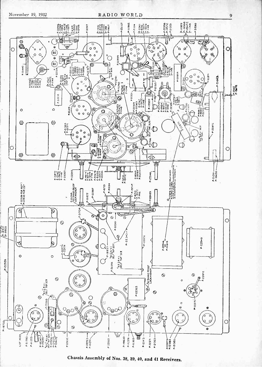
THE Stromberg-Carlson Models Nos.38, 39, 40 and 41 receivers are 10 -tube superheterodynes utilizing three
58s, one 57, one 56, two 55s, two 45s andone '80 tubes. They require 110 watts ofpower to operate and they give out anundistorted electrical power output of3.2 watts.
The three 58 tubes are used as r -famplifier, mixer 'and i-f amplifier. The 57tube is used as the "relay" tube in the"Q" circuit. The 56 is used as oscillatorand the two 55s are used as a. v. c., detec-tor and audio amplifier. The two 45 tubesare used in a push-pull output stage andthe '80 as a rectifier in the power supply.
The "relay" tube in the "Q" circuitmeans that the tube functions as a noisesuppression tube.
There are many similarities betweenthis circuit and that of the No. 37. Thepower supply is virtually the same from
(Contnued on ne.vt page)
1.5 fl)DUAOCA..A 10F. 0.11r
icirRaoZ 4
we.=
45 TUBE.,AVM oU T POT
551URT
56 TUBE09CRIATOR,
-WALOOV--WN. 6500"
000."
!,/ TURF_t..1.taY
PILOT
OTOHM5 MEGOI-IM5
RETA5TANCC3 OF AUDIO TRAN5roEmEt.)ARE. APPROXIMATE
ui
Schematic Circuit of Nos. 38, 39, 40, and 41 Receivers.

8 RADIO WORLD November 19, 1932
A POWER TRAN5E.
PRI
\ zeoPLATE
\noriL245
'T tHL:BLK-WH.
-HEATERS-5 CAPACITOR BLOCK
OR
1.1_
5L.- RED.
4 tHAF.L_51 -K -RED
(Continued from preceding page)the a -c plug to the voltage divider. Thefirst bi-resonator, the oscillator, the inter-stage coil, and the first detector are alsothe same except in a few minor details.The tri-resonator in the i-f amplifier,however, is of the band pass type.
BLUE
ORANGEORANGE --
81:1414 -E.' INPUT T AN5F.
BR DLK RED
BLK-14$4.
BLKIZED1R - RE()OUT PUT T ANSE 'et
3 .
"C: CAPACITOR BLOCK
Wiring Diagram of Nos. 38, 39, 40, and 41 Receivers.
The i-f amplifier is coupled to the 55demodulator by a single tuned circuittransformer. The resistor unit of the firstpotentiometer of the dual volume controlforms part of the load of the diode ofthis No. 55 tube. The audio voltage isapplied to the control grid of the triode
portion of this tube through the movablecontact of the potentiometer. The outputof this triode is connected to the grid ofthe triode of the first audio a. v. c. tubethrough a resistance coupling which in-cludes the second potentiometer of thevolume control.
November 19, 1932 RADIO WORLD
0
or
-:. 0-
N
N0-ti
0
7
0 N 0g VI; .)s? c, sti,^4302-n? ;cp.
ce. a a:
.1'C-7'1`4',".3 1'5
en.nr,-,1: ' Nra
a: a. is ei. ci-
r-
ON F NONI?
, ,II WI. 0- 0.
=Do
N
C.1
IA
NN N
T.1:0,I,,';.,';0 3))
W. 6, 6. O. a d.
O
'4)
.111,112_
to 0N 0
°ONOtr. A toN
N 2- V1') ° u,i III
4 P. a cLa
.
el t.10 0 0tr,
0. 0.
r -
2 ,r; 0mn
'1
1,1
ipakAILleraiMblor_d.
esJII:11..416.700,00weisomp
fJ0
d.
No e,N 10 010 ht rf
d. LC. ci
Ngsa-44.
Chassis Assembly of Nos. 38, 39, 40, and 41 Receivers.
10 RADIO WORLD November 19, 1932
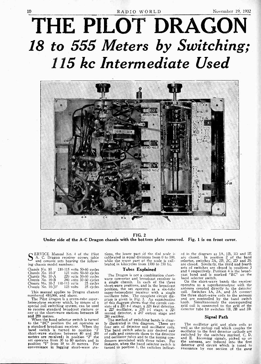
THE PILOT DRAGON18 to 555 Meters by Switching;
115 kc Intermediate Used
FIG. 2Under side of the A -C Dragon chassis with the bot tom plate removed. Fig. 1 is on front cover.
SERVICE Manual No. 4 of the PilotA. C. Dragon receiver covers tableand console sets bearing the follow-
ing chassis model numbers :Chassis No. 10 110-115 volts 50-60 cyclesChassis No. 10-F 125 volts 50-60 cyclesChassis No. 10-A 220 volts 50-60 cyclesChassis No. 10-B 240 volts 50-60 cyclesChassis No. 10-J 110-115 volts 25 cyclesChassis No. 10-JF 125 volts 25 cycles
This manual applies to Dragon chassesnumbered 410,000, and above.
The Pilot Dragon is a seven -tube super-heterodyne receiver which, by means of aspecial coil switching system, can be usedto receive standard broadcast stations orany of the short-wave stations between 18and 200 meters.
When the band selector switch is turnedto the "BC" position the set operates asa standard broadcast receiver. When theband switch is turned to position "3'short-wave stations between 80 and 200meters are received; in position "2" theset operates from 30 to 80 meters and inposition "1" from 18 to 30 meters. Forconvenience in logging short-wave sta-
tions, the lower part Of the dial scale iscalibrated in equal divisions from 0 to 100,while the upper part of the scale is cali-brated in, kilocycles from 1500 to 550 kc.
Tubes ExplainedThe Dragon is not a combination short-
wave converter and broadcast receiver ina single chassis. In each of the threeshort-wave positions, and in the broadcastposition, the set operates as a six -tubesuper -heterodyne receiver with a singleoscillator tube. The complete circuit dia-gram is given in Fig. 3. An examinationof this diagram shows that the circuit con-sists of a 235 r -f stage, a 224 first detector,a 227 oscillator, a 235 i-f stage, a 224second detector, a 247 output stage and280 rectifier.
The method of switching bands is clear-ly illustrated in this diagram. There arefour sets of detector and oscillator coils.The band switch selects any desired pairof coils and connects them to the detectorand oscillator tubes and to the tuning con-densers associated with these tubes. Forinstance, when the band selector switch isturned to position 1, the switches indicat-
ed in the diagram as 1A, 1B, 1D and 1Eare closed. In position 2 of the bandselector, switches 2A, 2B, 2C, 2D and 2Eare closed. Similarly, the third and fourthsets of switches are closed in positions 3and 4 respectively. Position 4 is the broad-cast band and is marked "BC" on theband selector switch.
On the short-wave bands the receiveroperates as a superheterodyne with theantenna coupled directly to the detectorcoil. Switches 1A, 2A, and 3A connectthe three short-wave coils to the antennaand are controlled by the band switchknob. Simultaneously the correspondinggrid coil is connected to the grid of thedetector tube by switches 1B, 2B and 3B.
Signal Path
The oscillator grid and plate coils aswell as the pickup coil which couples theoscillator to the first detector cathode areswitched by the switches marked, C, D,and E. Incoming signals, picked up onthe antenna, are induced into the firstdetector grid circuit which is tuned toresonance by one section of the gang

November 19, 1932 RADIO WORLD 11
RA' 235 15t. DET. 224 -A 2.35 2ND. DET 224A C-17 POWER 247
C18 PRE -SELECTOR
-16:1000
13 138 158 ;ElDET tiCOI LS
2-A
4-C 3-C
05C. GRIDC45
2-C
COILS
1-C
OSC. 227
C-9
R -I2
Tc-z R. R.
R2 C1 C-4
R- 5
I C-8
R-8
05 C LAT E § COILS
4-D § -D 2-D
R - I5
R-16 .r_fft
C-16
CATHODE
\13-E
COI L5
2-E
CONDENSERSC 1 - 25 mfd.C2 -.0005C3 -.0005G4 - .01C5 - 25C6-2.5C7 - 25CO - .1
C9 -.0001C10-3C11-8C12 -035C13-.25C14-.1C15-.001480C16-.1C17-.01C 18-.1
RESISTORSR1- 10 000 ern.,R2- 40000 - -R3-250000R4- 50000 -R5-500000R6-Cen+er."rap 11.1,0 -orR7- 10 000 ohms. VG.R 0- 250 - SW.
Schematic diagram of the A -C
condenser. The combination of the in-coming signal and the locally generatedoscillation produce a beat frequency of115 kc, which is amplified by the i-f ampli-fier. A trimmer condenser, connectedacross the grid coil of the first detector isadjusted at the factory to track the detec-tor and oscillator circuit.
When the band selector switch is turnedto the broadcast position, switches 4A, 4B,4C, 4D and 4E are closed and completethe same circuits as the correspondingswitches in the short wave bands. Asbefore, the gang condenser tunes the os-cillator grid circuit and the grid circuitof the first detector. Unlike the shortwave bands, however, the antenna is notcoupled directly to the grid circuit of thefirst detector. As shown in Fig. 3, incom-ing signals on the broadcast band firstpass through the pre -selector and the r -fstage before reaching the first detector.This arrangement of pre -selector andtuned r -f stage eliminates image interfer-ence on the broadcast band and providesextreme sensitivity.
Antenna Switching System
To make sure that broadcast signalspass through the pre -selector and r -fstage before reaching the first detector,it is necessary to eliminate any capacitybetween the antenna and the first detectorgrid circuit. To eliminate this capacity,the antenna is brought into a shieldedcompartment in which the broadcast an-tenna switch 4A and a special short waveantenna switch are enclosed. The latterconnects the antenna to the short waveband switches 1A, 2A and 3A when theband selector is in any of the three short
R 9 - 10000 ohms hwRIO- 10000R11- 14000 3WR12- 40000 AWR13-500000R14-120000R15- 10000R16- '.500R17- 300
.6. C-7
C-5
R.10
C-6
I4
R -i1
RE CT. 280
To ALLFIL.5.
DUAL VOLUME CONT ROLEACH SECTION 10,000 OHMSPART X . 100 OHMS
R-17
C-10 C-1.1
R13
R-14
SPEAKER SOCKET
SPEAKER PLUG
FIELD
SCHEMATIC DIAGRAMDRAGON MODEL 10 SUPER HET
FIG. 3Dragon for 18 to 555 meters. This is a seven -tube superheterodyne
(Model 10).
wave positions. In the broadcast positionthe short wave antenna switch is openand switch 4F is closed. The lattergrounds contacts 1A, 2A and 3A, togetherwith the wire connecting these contactstogether. All undesired capacity in thewiring of the switch is thus eliminated.
The i-f amplifier is tuned to 115 kc,with a total of four tuned circuits. Thetwo trimmers in each i-f transformer areadjusted through holes in the top of thecan.
The second detector operates as a self -biased power detector and is resistance-coupled to the pentode output stage. The50,000 ohm resistor, between the plate ofthe 224 and the coupling condenser, pre-vents r -f signals from reaching the gridof the pentode, the r -f component beingby-passed by two fixed condensers.
Power Supply and Volume ControlThe plate voltages of all tubes, except
the oscillator, are supplied directly fromthe positive side of the line. The plate ofthe oscillator, together with the screengrids of the first detector and i-f tubes,are supplied from the 90 volt tap on thebleeder across the power supply. Thescreen grid of the second detector is con-nected to the 45 volt tap.
Volume is controlled by varying thegrid bias of the 235 i-f amplifying tube.On the broadcast band, the volume con-trol also varies the r -f tube bias and theresistance from antenna to ground, thisadditional control being necessary to re-duce strong local stations to complete in-audibility.
At the rear of the chassis, a phonographpick-up jack is provided. When the pick-up is plugged in, it connects between the
low side of the i-f transformer andground. A high impedance pick-upshould be used. The radio volume controlshould be turned to its minimum position.
A jack is also provided for those whowish to tune in stations with headphones.The phones connect across the output ofthe second detector. No direct currentflows through the phones and there is nodanger of shock. High impedance head-phones should be used.
Re -AlignmentThe sensitivity and selectivity of the
Pilot Dragon largely depend upon theproper adjustment of the various trimmercondensers. Before sets leave the factory,these trimmers are carefully tuned andevery precaution is taken to insure thepermanence of the adjustments.
If a set appears to be insensitive, it ispossible that rough handling in transithas changed the position of some of thetrimmers. In this case, the sensitivity canbe restored by re -aligning the set. It isunderstood, of course, that the tubes havebeen checked and other tests made, assuggested in the foregoing sections, tomake sure that the insensitivity is not dueto other causes.
The best method of adjusting the i-ftrimmers is by means of a signal genera-tor (or modulated oscillator) tuned to 115kc. The output of the oscillator is con-nected across the grid circuit of the firstdetector and the two i-f transformers arelined, up to resonance with the 115 kc sig-nal. Many service stations, however, maynot be equipped with a 115 kc oscillator,in which case the i-f transformers can beadjusted at the same time as the broad -
(Continued on page 14)
12 RADIO WORLD November 19, 1932
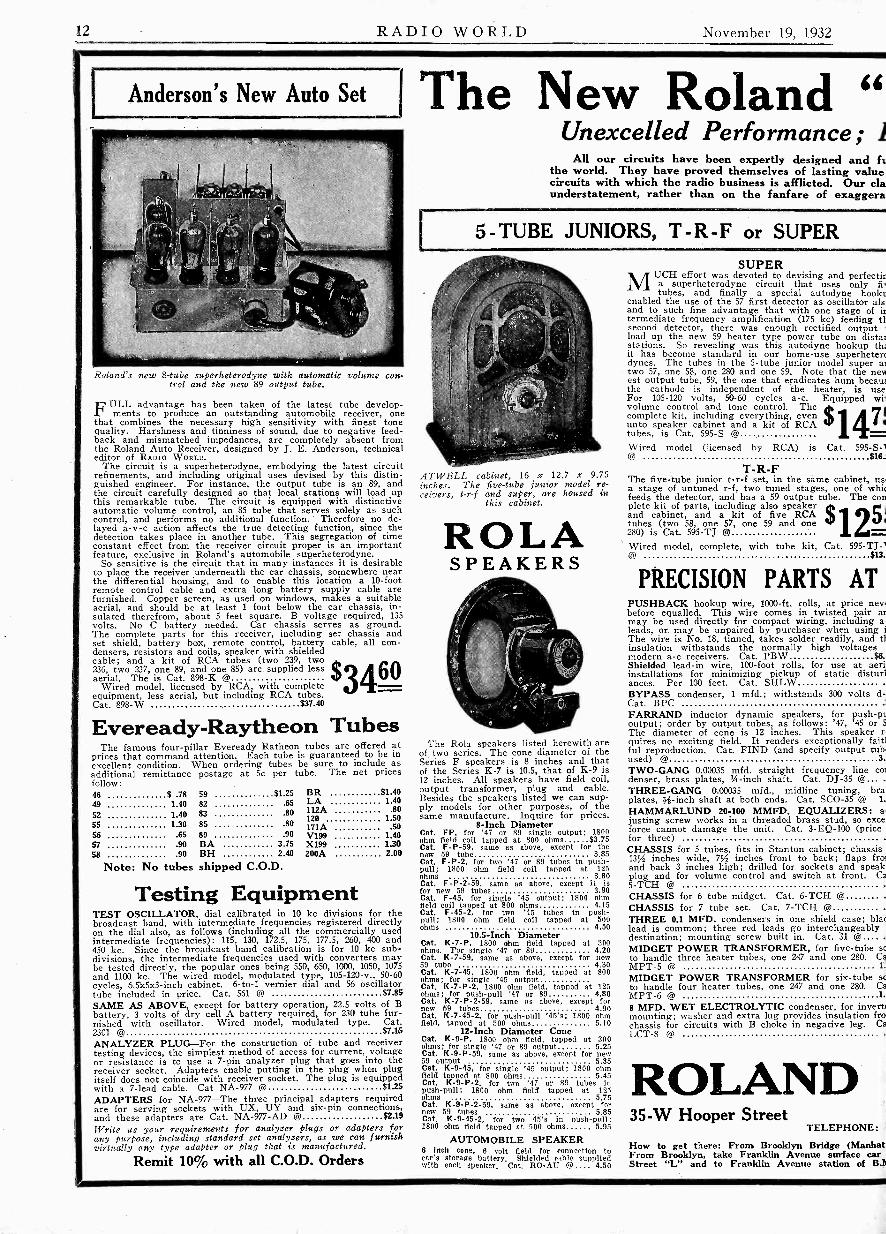
Anderson's New Auto Set
Roland's new 8 -tube superheterodyne with automatic volume con-trol and the new 89 output tube.
ULL advantage has been taken of the latest tube develop-!' ments to produce an outstanding automobile receiver, onethat combines the necessary high sensitivity with finest tonequality. Harshness and tinniness of sound, due to negative feed-back and mismatched impedances, are completely absent fromthe Roland Auto Receiver, designed by J. E. Anderson, technicaleditor of RADIO WORLD.
The circuit is a superheterodyne, embodying the latest circuitrefinements, and including original uses devised by this distin-guished engineer. For instance, the output tube is an 89, andthe circuit carefully designed so that local stations will load upthis remarkable tube. The circuit is equipped with distinctiveautomatic volume control, an 85 tube that serves solely as suchcontrol, and performs no additional function. Therefore no de-layed a -v -c action affects the true detecting function, since thedetection takes place in another tube. This segregation of timeconstant effect from the receiver circuit proper is an importantfeature, exclusive in Roland's automobile superheterodyne.
So sensitive is the circuit that in many instances it is desirableto place the receiver underneath the car chassis, somewhere nearthe differential housing, and to enable this location a 10 -footremote control cable and extra long battery supply cable arefurnished. Copper screen, as used on windows, makes a suitableaerial, and should be at least 1 foot below the car chassis, in-sulated therefrom, about 5 feet square. B voltage required, 135volts. No C battery needed. Car chassis serves as ground.The complete parts for this receiver, including set chassis andset shield, battery box, remote control, battery cable, all con-densers, resistors and coils, speaker with shieldedcable; and a kit of RCA tubes (two 239, two236, two 237, one 89, and one 85) are supplied lessaerial. The is Cat. 898-K @ 3460
Wired model, licensed by RCA, with completeequipment, less aerial, but including RCA tubes.Cat. 898-W $37.40
Eveready-Raytheon TubesThe famous four -pillar Eveready Ratheon tubes are offered at
prices that command attention. Each tube is guaranteed to be inexcellent condition. When ordering tubes be sure to include asadditional remittance postage at 5c per tube. The net pricesfollow:46 $ .78 59 $1.25 BR $1.40
49 1.40 82 .65 LA 1.40
52 1.40 83 .80 112A .80
SS 1.30 85 .80120 1.50171A
.S056 .65 89 -90 V199 1.4057 .90 BA 3.75 X199 1.3058 .90 BH 2.40 200A 2.00
Note: No tubes shipped C.O.D.
Testing EquipmentTEST OSCILLATOR, dial calibrated in 10 kc divisions for thebroadcast band, with intermediate frequencies registered directlyon the dial also, as follows (including all the commercially usedintermediate frequencies): 115, 130, 172.5, 175, 177.5, 260, 400 and450 kc. Since the broadcast band calibration is for 10 kc sub-divisions, the intermediate frequencies used with converters maybe tested directly, the popular ones being 550, 650, 1000, 1050, 1075and 1100 kc. The wired model, modulated type, 105-120-v., 50-60cycles, 6.5x5x3-inch cabinet. 6 -to -1 vernier dial and 56 oscillatortube included in price. Cat. 561 @ $7.85
SAME AS ABOVE, except for battery operation, 22.5 volts of Bbattery, 3 volts of dry cell A battery required, for 230 tube fur-nished with oscillator. Wired model, modulated type. Cat.2301 @ $7.15
ANALYZER PLUG-For the construction of tube and receivertesting devices, the simplest method of access for current, voltageor resistance is to use a 7 -pin analyzer plug that goes into thereceiver socket. Adapters enable putting in the plug when plugitself does not coincide with receiver socket. The plug is equippedwith a 7 -lead cable. Cat NA -977 @ $1.25
ADAPTERS for NA-977-The three principal adapters requiredare for serving sockets with UX, UY and six -pin connections,and these adapters are Cat. NA -977 -AD @ $2.19
Write us your requirements for analyzer plugs or adapters forany purpose, including standard set analyzers, as we can furnishvirtually any type adapter or plug that is manufactured.
Remit 10% with all C.O.D. Orders
The New Roland "Unexcelled Performance;
All our circuits have been expertly designed and ftthe world. They have proved themselves of lasting valuecircuits with which the radio business is afflicted. Our claunderstatement, rather than on the fanfare of exaggera
5 - TUBE JUNIORS, T -R-F or SUPER
ATWELL cabinet, 16 x 12.7 x 9.75inches. The five -tube junior model re-ceivers, t -r -f and super, are housed in
this cabinet.
ROLASPEAKERS
The Rola speakers listed herewith areof two series. The cone diameter of theSeries F speakers is 8 inches and thatof the Series K-7 is 10.5, that of K-9 is12 inches. All speakers have field coil,output transformer, plug and cable.Besides the speakers listed we can sup-ply models for other purposes, of thesame manufacture. Inquire for prices.
8 -Inch DiameterCat. FP, for '47 or 89 single output; 1800ohm field coil tapped at 300 ohms $3.75Cat. F -P -59, same as above, except for thenew 59 tube 3.85Cat. F -P-2, for two '47 or 89 tubes in push-pull; 1800 ohm Held coil tapped at 125ohms 3.80Cat. F -P -2 -59, same as above, except it isfor new 59 tubes 3.90Cat. F-45, for single '45 output; 1800 ohmfield coil tapped at 800 ohms 4.15Cat. F-45.2, for two '45 tubes in push-pull; 1800 ohm field coil tapped at 500ohms 4.50
10.5 -Inch DiameterCat. K -7-P. 1800 dim field tapped at 300ohms. For single '47 or 89 4.20Cat. K-7-59, same as above, except for new59 tube 4.30Cat. K-7-45, 1800 ohm field, tapped at 800ohms; for single '45 outputCat. K -7- P-2, 1800 ohm field, tapped at 125ohms; for push-pull '47 or 89 4.80Cat. K -7-P-2-59, same as above, except fornew 59 tubes 4.90Cat. K-7-45-2, for push-pull '45's; 1800 ohmfield, tapped at 500 ohms 5.10
12 -Inch Diameter ConeCat. K -9-P, 1800 ohm field, tapped at 300ohms; for single '47 or 89 output 5.25Cat. K -9-P-59, same as above, except for new59 output 5.35Cat. K-9-45, for single '45 output; 1800 ohmfield tapped at 800 ohms 5.45Cat. K -9-P-2. for two '47 or 89 tubes inpush-pull; 1800 ohm field tapped at 125ohms 5.75Cat. K -9-P-2-59, same as above, except fornew 59 tubes 5.85Cot, K-9-45-2, for two 45's in push-pull:1800 ohm field tapped at 500 ohms 5.95
AUTOMOBILE SPEAKER6 Inch cone, 6 volt field for connection tocar's storage battery. Shielded cable suppliedwith each speaker. Cat. RO-AU 4.50
SUPERMUCH effort was devoted to devising and perfectir
a superheterodyne circuit that uses only fi
tubes, and finally a special autodyne hooktenabled the use of the 57 first detector as oscillator als,and to such fine advantage that with one stage of istermediate frequency amplification (175 kc) feeding tlsecond detector, there was enough rectified output I
load up the new 59 heater type power tube on distalstations. So revealing was this autodyne hookup theit has become standard in our home -use superheteredynes. The tubes in the 5 -tube junior model super aitwo 57, one 58, one 280 and one 59. Note that the nesiest output tube, 59, the one that eradicates hum becau:the cathode is independent of the heater, is useFor 105-120 volts, 50-60 cycles a -c. Equipped witvolume control and tone control. Thecomplete kit, including everything, even 471unto speaker cabinet and a kit of RCAtubes, is Cat. 595-S @Wired model (licensed by RCA) is Cat. 595-S-1
$16.1
T -R -FThe five -tube junior t -r -f set, in the same cabinet, us,a stage of untuned r -f, two tuned stages, one of whitfeeds the detector, and has a 59 output tube. The conplete kit of parts, including also speakerand cabinet, and a kit of five RCA
251tubes (two 58, one 57, one 59 and one280) is Cat. 595-TJ @Wired model, complete, with tube kit, Cat. 595-TJ-1
$13.
PRECISION PARTS ATPUSHBACK hookup wire, 1000 -ft. rolls, at price nevibefore equalled. This wire comes in twisted pair asmay be used directly for compact wiring, including a.leads, or may be unpaired by purchaser when using iThe wire is No. 18, tinned, takes solder readily, and tlinsulation withstands the normally high voltagesmodern a -c receivers. Cat. PBW $6.:Shielded lead-in wire, 100 -foot rolls, for use at aeriinstallations for minimizing pickup of static disturlances. Per 100 feet. Cat. SHLWBYPASS condenser, 1 mfd.; withstands 300 volts d -Cat. BPCFARRAND inductor dynamic speakers, for push -ptoutput; order by output tubes, as follows: '47, '45 or 5The diameter of cone is 12 inches. This speaker nquires no exciting field. It renders exceptionally faitlful reproduction. Cat. FIND (and specify output tubused) @ 3'TWO -GANG 0.00035 mfd. straight frequency line co:denser, brass plates, 14 -inch shaft. Cat. DJ -35 @... .1THREE -GANG 0.00035 mfd., midline tuning, braplates, ;i-inch shaft at both ends. Cat. SCO-35 @ 1.
HAMMARLUND 20-100 MMFD. EQUALIZERS: a:justing screw works in a threaded brass stud, so exce,
force cannot damage the unit. Cat. 3-EQ-100 (pricefor three)CHASSIS for 5 tubes, fits in Stanton cabinet; chassis1314 inches wide, 7.f inches front to back; flaps fro:and back 3 inches high; drilled for sockets and speakplug and for volume control and switch at front. Ca5-TCH @CHASSIS for 6 tube midget. Cat. 6-TCH @CHASSIS for 7 tube set. Cat. 7-TCH @THREE 0.1 MFD. condensers in one shield case; blaclead is common; three red leads go interchangeably I
destination; mounting screw built in. Cat. 3I @....MIDGET POWER TRANSFORMER, for five -tube seto handle three heater tubes, one 247 and one 280. CaMPT-5 @ 1.
MIDGET POWER TRANSFORMER for six -tube seto handle four heater tubes, one 247 and one 280. CaMPT- 6 @8 MFD. WET ELECTROLYTIC condenser, for invert:mounting; washer and extra lug provides insulation frochassis for circuits with B choke in negative leg. CaLCT -8 @
ROLAND35-W Hooper Street
TELEPHONE:
How to get there: From Brooklyn Bridge (ManhatlFrom Brooklyn, take Franklin Avenue surface carStreet "L" and to Franklin Avenue station of B.11

November 19, 1932 RADIO WORLD 13
lower Plus" Circuitsyes Lower Than Ever Beforecsted not only in our laboratories but also in the markets ofare by no means to be confused with experimental or giddy
performance are modest, and we rely on the strength ofRoland is a name that stands for reliability.
4 -TUBE T -R -F RECEIVERHE accomplishment of real results, including notonly the enjoyable reception of local stations butconsiderable distance reception as well, under fav-
'able conditions, is possible with the Roland 594-Tceiver. The tuned r -f stage has a 58 tube, the detec-r a 57, the rectifier is a 280, while the output tube ise new 59. This receiver is stable in operation, pro-
nces good tone, and has a sensitivity far in excess ofthat would normally be expected of a 4 -tube t -r -ffceiver. Every precaution has been taken to safeguardgainst radio frequency losses, so that the fullestssible sensitivity and selectivity would result. Thereno room for losses in so modest a set, and we have
iminated them very successfully. The result is atube t -r -f receiver that has been acclaimed the leaderits class. Moreover, the price is at such a reduced
vel that no one can say he can't afford a good,ceiver. This is indeed a good one and we recommendhighly, despite its few tubes and low cost.
This receiver is sold in wired form only, and isensed by RCA. Moreover, despite the very low price,comes complete in all respects, including also the
t of four RCA tubes (one 58, one 57, one 280 and one). Speaker of course is included.
quipped with volume control and tonepntrol. Cat. 594-T @
or 105-120 volts, 50-60 cycles a -c $ 195
.his four -tube set is, in our opinion, the best four -tubet made to sell in the $25 to $37 price range of com-titors.
IKINGLY LOW PRICES(Coil shields, 2 -inch diem., 2.5 inches high.)
5 kc, shielded intermediate coils, primary and second -y tuned by Hammarlund condensers built in,
oscillator, where4Nab
around
Oscillatorommodulator
attached,
1.391ro
m-
kc, same as above, except for difference in fre-ency. For short-wave supers. Cat. INT-1500 .97
t, three shielded t -r -f coils for 0.00035 mfd. T -r -fils have 80 -meter tap (lug inside coil), which need not
used if not desired. Cat. TRF-L 1.19TURN HONEYCOMB coil, total diameter, 1% inches;
ill tune to 175 kc. with 0.0001 mfd. (or 20-100 mmfd.3ualizer). Cat. HC -800 @ .3080 TURN HONEYCOMB coil, same style, tunes to 400c. with 0.0001 mfd. Also may be used without con-enser as antenna input coil, screen and plate choking,
two used inductively coupled for evening the ampli-. cation of t -r -f sets, in untuned stage feeding detector.`at. HC -300 (each) @ .20
TURN HONEYCOMBN coil, 34 millihenry, for all shortave purposes. Cat. HC -50 @ .15WATT PIGTAIL RESISTORS, all resistance values.
fention Cat. PGTR and state resistance in ohms there -ter. Price .07OTENTIOMETERS: 400 ohms at 27c; 5,000 ohms @
; 25.000 ohms @ 75c; 50,000 ohms @ 75c; 100,000ms @ 80c; 500,000 ohms @ 80c.OTENTIOMETER with a -c switch attached, 10,000ms, for variable mu grid bias as volume control.
'at. POT -10 -SW @ .79ALNUT FINISH, EITHER DORSET OR STANTON
ABINET for midget sets, cut for 7 -inch cone. Cat.DCB @ 4.50
REE GANG .0005 MFD. Cat. DJA-35 @ 1.2SELFORD 30 henry choke; stands up to 100 ma; inlack shield case. Cat. KEL-30 @ .93i.5 VOLT center -tapped fil. trans., 2 amperes Cat.LT @ .79
ADIO CO.Brooklyn, N. Y.
14.MSBURG 5-0043
eke Graham Avenue surface car to Classon Avenue.Koper Street. Franklin Avenue car connects to Fultontighton line.
BOSWORTH cabinet, 14 x 11.5 x 9.5inches, housing the 4 -tube t -r -f set.
SIX - TUBED -C CIRCUIT
For 110 -volt d -c locations we have an ex-cellent 6 -tube set. Parts include speakerand Stanton cabinet, and kit of RCA tubes(two 239, one 236, one 237 and. two 238's inpush-pull). Cat. 386-T $21.75
Wired model, with cabinet, speaker,tubes. Cat. 386 -T -W ' , 23.50
SHORTWAVESOne set of four special plug-in
coils $1.25One HamMarlund 0.00014 mfd. tuning
condenser 1.15One Hammarlund 0.0002 mfd, feed-
back condenser 1.25Three UX sockets .18One audio transformer .50One 50,000 -ohm resistor .08
7 -Tube SuperTHE best chassisthat we make,
housed in our mostluxurious table modelStanton cabinet, is theseven -tube superhetero-dyne. This receiver isnoted not only for itsmost exceptionally ex-quisite tone but alsofor its extraordinaryability at bringing infar -distant stations, in-cluding stations of ex-tremely low power. Un-der normal conditionsthe night-time range ofthis receiver is estimat-ed to be 3000 miles. SoDX fans will get theirfull measure of delightfrom the 597-S receiver,the most sensitive andmost selective of theRoland line of receiversand kits.
The set is for a -c op-eration, uses the newestand best tubes, withtwo 59 tubes in the out-put. These new output tubes eradicatecathode is independent of the a -c heater.
The circuit completely suppresses forms of interferencepeculiar to superheterodynes, including image reception. Thissuppression is due to the high' selectivity developed, includingthe selectivity ahead of the ntermediate channel. All toldthere are seven tuned circuits, although only three are con-trolled by the three -gang tuning condenser. The stations arefar enough separated on the dial on a frequency basis to maketuning easy despite the high selectivity. Care has been takento avoid sideband suppression. Tone is one of the first con-siderations in all Roland Receivers and .has been most care-fully protected in our seven -tube quintessence of excellence.
The intermediate frequncy is 175 kc, the mixer has a stageof t -r -f ahead of it, modulator and oscillator are tuned, andthe sensitivity built up so high that the average is betterthan 2 microvolts per meter, and at the high frequency endthe sensitivity attains levels approximating 0.25 microvoltsper meter. For the man or woman who knows his or herradio this is the receiver par excellence.
The Roland autodyne circuit is used, whereby oscillator andmodulator are combined in one tube, and in a manner that,far from being less desirable than where two separate tubesare used, is, if anything, more desirable, because of electroncoupling. The receiver is available l either in kit form or wired.
Complete kit, including cabinet and speaker, and alsoincluding a kit of RCA tubes (two 58, two 57,two 280 and two 59), for 105-120 volts, 50-60 22 95cycles a -c. Equipped with volume controland tone control. Cat. 597-SWired model, with tubes, including cabinetand speaker. Cat. 9 597 -S -W $26.95
THE STANTON cabinet intowhich are put the 7 -tube a -c
super or the 6 -tube d -c set.
hum because the
TWO -TUBE BATTERY MODELOur two -tube 15 -200 -meter circuit for earphone work is excel-
lent one and has proved its popularity for many years. The 2 -volttubes (237) are used, in detector and one stage of transformer audio,with Hammarlund tuning condenser of 0.00014 mfd. and a Hammar-lund feedback condenser of 0.0002 mfd. capacity. This hookup isvirtually standard with short-wave enthusiasts, especially those keenon European reception.
The complete kit of parts, with picture diagram of the wiring, isobtainable at only $7,95 (Cat. SWBAT-K), and a wired model at only$1 extra (Cat. SWBAT-W). Herewith is the list of parts and prices:
honeycomb choke.. .25 li EL vernier dial .70One 0.00025 mfd. grid condenser with Two knobs .10.08 One 7x10 inch front panel, bake -One 6.5 ohm filament resistor .12 1.20
One equalizer
lite.
One 20 -ohm rheostat One baseboard 25
One battery switchOne blueprint -Six binding posts
Binding post strip
Economical ConverterA. short-wave converter, 20 to 200 meters, that also may tunesomewhat into the broadcast band, depending on what intermediate
frequency is used, can be built economically. While the appear-ance is not the best possible to attain, due to economical cost,the converter is nevertheless good on performance, especially asmodulator and oscillator are separately tubed. The wave bands arechanged by plugging tipped leads into each of the band sockets,at corresponding positions. Many users of this converter, whichthey themselves built, have expressed their delight at its per-formance. And it works on superheterodynes as well as on t -r -tsets, which is not true of all converters. A plain wooden box,stained, is used for Cabinet, and is supplied with the rest of theparts. The tubes used are three 237's. For a -c operation, 105-120v, 50-60 c. The complete kit of parts, including cabinet, allresistors, condensers and coils, and a kit of three tubes, isCat. ECONV $7.95Wiring diagram ss furnished free with each kit.
Short -Wave PartsHAMMARLUND 0.0002 mfd. junior midline condenser, popular forfeedback control in short-wave circuits. Isoltantite base. Cat,11-20 (0) $1.25HAMMARLUND 0.00014 mfd. Junior midline tuning condenser,the capacity used for virtually all short:wave tuning. Isolantitebase. Cat. H-14 (§ 1.15HAMMARLUND 0.00014 mfd. dual condenser (two sections) ,Isolantite base. Cat. IL -14 -DUO Q 2.05Set of four plug -in -coils, two windings, UX bases; for use ofUX tube sockets as coil receptacles. Gripping Range on each, alsodifferent color code on each flange for each coil. Cat.SWL-UX. 1.30Set of four plug-in roils, three windings, six -pin bases; for useof six -pin tube sockets as coil receptacles. Third winding is forfeedback. Useful for single tube sot or for regenerative detectorwhere set has stage of t -r -f. Cat. SWL-SXP 1.65Short-wave r -f choke, inductance 14 millihenry, Honeycomb type.Cat, HC -50 .15Blueprint of two -tube battery -operated short-wave earphone set andof four -tube set, same as two -tube, except for two stages of audio.(Both.) Cat. BP -SW -2-4 Q .15
.25
.15.10.24 Cat. SWEAT- K (complete kit, less.10 tubes, cabinet) $7.95
Blueprint furnished free with each kit
The Economical converter is a -c operated andhas its own power supply built in, includingtwo 8 mfd. condensers and a suitable B choke.The two dials tune in short waves when theconverter is connected to the antenna post ofthe receiver. Aerial then goes to converterinstead of to set.
Remit 10% with all C.O.D. Orders
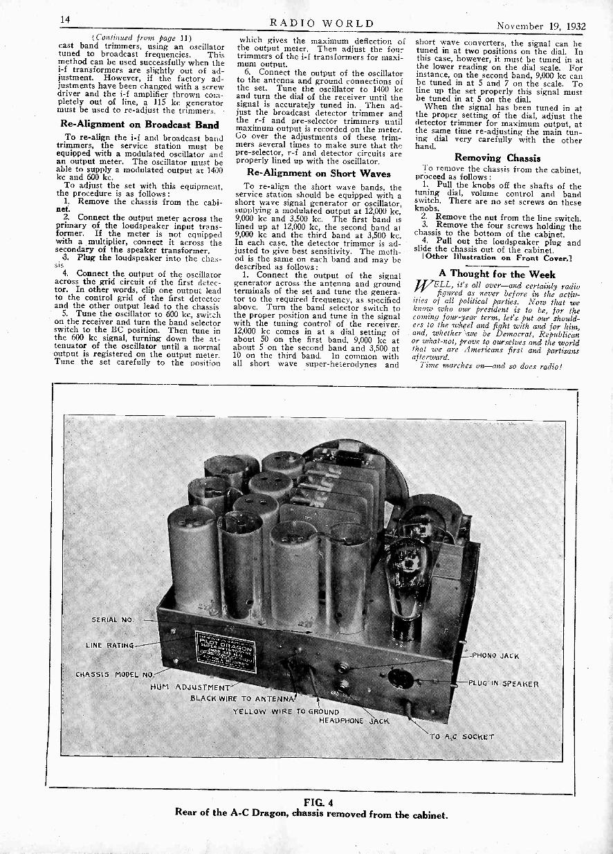
14 RADIO WORLD November 19, 1932(Continued from page 11)
cast band trimmers, using an oscillatortuned to broadcast frequencies. Thismethod can be used successfully when thei-f transformers are slightly out of ad-justment. However, if the factory ad-justments have been changed with a screwdriver and the i-f amplifier thrown com-pletely out of line, a 115 kc generatormust be used to re -adjust the trimmers.
Re -Alignment on Broadcast BandTo re -align the i-f and broadcast band
trimmers, the service station must beequipped with a modulated oscillator andan output meter. The oscillator must beable to supply a modulated output at 1400kc and 600 kc.
To adjust the set with this equipment,the procedure is as follows:
1. Remove the chassis from the cabi-net.
2. Connect the output meter across theprimary of the loudspeaker input trans-former. If the meter is not equippedwith a multiplier, connect it across thesecondary of the speaker transformer.
3. Plug the loudspeaker into the chas-sis
4. Connect the output of the oscillatoracross the grid circuit of the first detec-tor. In other words, clip one output leadto the control grid of the first detectorand the other output lead to the chassis
5. Tune the oscillator to 600 kc, switchon the receiver and turn the band selectorswitch to the BC position. Then tune inthe 600 kc signal, turning down the at-tenuator of the oscillator until a normaloutput is registered on the output meter.Tune the set carefully to the position
which gives the maximum deflection ofthe output meter. Then adjust the fourtrimmers of the i-f transformers for maxi-mum output.
6. Connect the output of the oscillatorto the antenna and ground connections ofthe set. Tune the oscillator to 1400 kcand turn the dial of the receiver until thesignal is accurately tuned in. Then ad-just the broadcast detector trimmer andthe r -f and pre -selector trimmers untilmaximum output is recorded on the meter.Go over the adjustments of these trim-mers several times to make sure that thepre -selector, r -f and detector circuits areproperly lined up with the oscillator.
Re -Alignment on Short WavesTo re -align the short wave bands, the
service station should be equipped with ashort wave signal generator or oscillator,supplying a modulated output at 12,000 kc,9,000 kc and 3,500 kc. The first band islined up at 12,000 kc, the second band at9,000 kc and the third band at 3,500 kc.In each case, the detector trimmer is ad-justed to give best sensitivity. The meth-od is the same on each band and may bedescribed as follows :
1. Connect the output of the signalgenerator across the antenna and groundterminals of the set and tune the genera-tor to the required frequency, as specifiedabove. Turn the band selector switch tothe proper position and tune in the signalwith the tuning control of the receiver.12,000 kc comes in at a dial setting ofabout 50 on the first band, 9,000 kc atabout 5 on the second band and 3,500 at10 on the third band. In common withall short wave super -heterodynes and
short wave converters, the signal can betuned in at two positions on the dial. Inthis case, however, it must be tuned in atthe lower reading on the dial scale. Forinstance, on the second band, 9,000 kc canbe tuned in at 5 and 7 on the scale. Toline up the set properly this signal mustbe tuned in at 5 on the dial.
When the signal has been tuned in atthe proper setting of the dial, adjust thedetector trimmer for maximum output, atthe same time re -adjusting the main tun-ing dial very carefully with the otherhand.
Removing ChassisTo remove the chassis from the cabinet,
proceed as follows :1. Pull the knobs off the shafts of the
tuning dial, volume control and bandswitch. There are no set screws on theseknobs.
2. Remove the nut from the line switch.3. Remove the four screws holding the
chassis to the bottom of the cabinet.4. Pull out the loudspeaker plug and
slide the chassis out of the cabinet.[Other Illustration on Front Cover.]
A Thought for the WeekjJELL, it's all over-and certainly radio
figured as never before in the activ-ities of all political parties. Now that weknow who our president is to be, for thecoming four-year term, lees. put our should-ers to the wheel and fight with and for him,and, whether we be Democrat, Republicanor what -not, prove to ourselves and the worldthat we are Americans first and partisansafterward.
Time marches on and so does radio!
SERIAL NO.
LINE RATING
CHASSIS MODEL NO.
HUM ADJUSTMENTBLACK WIRE TO ANTENNA
YELLOW WIRE TO GROUNDHEADPHONE J GK
PHONO JACK
PLUG IN SPEAKER
TO A.S. SOCKET
FIG. 4Rear of the A -C Dragon, chassis removed from the cabinet.

November 19, 1932 RADIO WORLD 15
Circuit Analysis of Philco 15
/i.optcuitCC/ /44 /44
I
A
[The general service information on theModel 15 Philco was published in the Octo-ber 29th issue. All resistance and capacityvalues were given. Herewith is an analysisof the circuit.-EDIToR.]
THEModel 15. Receiver is an 11 tubesuperheterodyne embodying all thebest features known in radio set
designing.The analysis of the circuit should be
followed on the wiring diagram.The antenna is connected to Coil No. 2.
which is shunted by Resistor No. 1. CoilNo. 2 and No. 7 comprise what is actuallytermed a "Pre -Selector Circuit," fhat is,the signal which is applied .to the first 44Tube is very carefully selected from un-wanted signals by means of two tunedcircuits. These two circuits are coupledby means of the small coil at the bottomof No. 7. The signal being applied to the44 Tube is very carefully selected fromunwanted signals by means of two tunedcircuits. These two circuits are coupledby means of the small coil at the bottomof No. 7. The signal being applied to the44 Tube is amplified and the signal in theplate circuit is coupled to the secondaryof Coil No. 15 by means of two primaries.
Why Two Primaries Are UsedThe top primary in the diagram is tuned
by Condenser No. 11. These two primariesare used in order to secure uniformamplification throughout the range offrequencies covered by this set. Alsocoupled to Transformer No. 15 is theOscillator Coil No. 19. At this point thesignal is heterodyned against the localoscillator in the set to produce the hetero-dyne frequency which will be amplifiedby the I. F. system.
In this receiver, the oscillator willalways be tuned to 175 kilocycles higherthan the incoming signal. This oscillatorcircuit is rather unique, in that it gives auniform output over the broadcast fre-quency band. This is accomplished by thefact that the circuit combines both induc-tive and capacitive coupling by means ofthe Plate Coil and Series CondensersNos. 20 and 22. By using this circuit, nodanger of overloading the first detectoris encountered by having too strong oscil-lator voltage at one end of the band. Thisoscillator is also of the fixed bias type,thereby keeping harmonics generated inthe oscillator to a very low order.
The Intermediate FrequencyThe resultant frequency, which is
44
By David EarnshawPhilco Research Department
2" I F.
44
DET. RECTIFIER
37
A
I., MOM37
NOTE: SWITENES 6AN6ED AS SHOWN2 --J
generated when the signal and the oscil-lator beat together, appears in the platecircuit of the first detector and is ampli-fied by the first I.F. amplifier stage. Thetransformer feeding this first I.F. Tubeis a double tuned transformer in order toobtain a very high order of selectivity. Itis tuned both primary and secondary sothat none other than the desired fre-quency can he amplified by the first tube.
A pure signal thus being obtained in theI.F. Amplifier, this signal is amplified bythe two succeeding stages which aretuned only in their secondary circuit. Bytuning only the secondary circuit andproperly designing the transformer, anI.F. system can be made which does notcut as many side bands as would be cutby an I. F. system in which both primaryand secondary coils are tuned. The ques-tion as to whether all transformers musthe tuned both primary and secondary,must be answered by the amount of totalselectivity required in the set.
Second DetectionThe signal has now reached the stage
where it must be converted into its audiomodulation, that is, demodulated. This isaccomplished in the Type 37 DetectorRectifier. This tube, when connected inthe manner shown, is a Diode Rectifier,that is, any signal which is impressedupon it is directly proportional to theoutput. This means that when receivinga given signal and the modulation is in-creased, the audio output will go up indirect proportion. This is a very impor-tant feature which is very difficult to ob-tain except by using a diode type recti-fier.
At the same time that this signal isrectified, two components are developedin Resistors Nos. 40 and 43. One is theD.C. component and the other isthe audio
impressedupon
envelope which wasupon the carrier. This D.C., which isgenerated, is proportional to the strengthof the carrier voltage which is beingdeveloped on the diode rectifier. There-fore, if this D.C. voltage is fed back andallowed to control the grids of the R.F.and I.F. Amplifiers, it will tend to makethe voltage which is developed across thediode constant for all signal levels im-pressed between antenna and ground. Ofcourse this voltage, which is generated inthe diode, contains a certain amount ofthe intermediate frequency which must befiltered out before it is applied to thesetubes.
2. AUDIO
37
OUP, -PULE
OUTPUTMEN
.-6Rf ENS WHITE
This filtering is accomplished by meansof Resistor No. 40 and Condensers Nos.41 and 42, also by Resistor Nos. 28, 17and 9 with their asociated by-pass con-densers.
Audio AmplifierWith the perfection of the exponen-
tial tube, the Type 44, it is possible todesign a set such as this model which iscapable of handling the extremes of allsignal strength which may be applied tothe antenna.
The audio frequency, which is developedacross Resistor No. 43, is now applied tothe grid of the first audio amplifierthrough Condenser No. 44. Resistor No.43 is the volume control which determinesthe desired volume level of the signals.This audio frequency is amplified by thefirst and second audio tubes which areresistance coupled in order to secure goodfrequency characteristics. It is thenapplied through the push-pull transformerto the grids of the push-pull 42 Tubes.and thence to the speakers.
The tone control on this set is accom-plished by placing various capacity con-densers (53) across the plate of thesecond audio tube.
On this model there is incorporatedshadow tuning, that is, an indicator whichwill show when the set is correctly tuned.This is accomplished by placing the deviceso that it receives the plate current of thefirst I.F. and the first detector circuits.
As can be seen from the previous dis-cussion regarding the action of the auto-matic volume control, a variable voltageis applied to the grids of these tubes inorder to accomplish automatic volumecontrol. This causes the variation in gainin these circuits which is accompanied bya variation in plate current. Therefore,as the signal is tuned through when tun-ing the gang condenser, the voltagedeveloped in the diode circuit reaches amaximum when the signal is correctlytuned. Consequently this means that theplate current in the first detector andI.F. Tubes will reach a minimum for thatgiven signal when the carrier is correctlytuned. This is indicated by the width ofthe shadow in the shadow tuning box;the smaller the shadow, the lower is thecurrent in these tubes.
Proportional DifferenceAs can be seen from this explanation,
the width of the shadow is dependent(Continued on next page)
16 RADIO WORLD November 19, 1932
WHAT INTERMEDIATE?Importance of the Frequency Discussed
By Einar AndrewsWHAT intermediate frequency isbest in a superheterodyne? The
best frequency is one that is higherthan the highest modulation frequencyand lower than the lowest signal fre-quency that is to be received with thesuperheterodyne. For broadcast receptionthis leaves a choice of almost anyfrequency between 30 and 500 kc.
There are certain principles that mustbe kept in mind in selecting the fre-quency. First, it must not be too low, orthe circuit is likely to be so selective thatonly low audio frequencies can be re-ceived without tone correction in theaudio amplifier. Second, it must not beso low as to make it impossible to elimi-nate image interference. Third, it mustnot be so high as to make close paddingdifficult. Fourth, it must not be so highthat it lies near the lowest frequency towhich the radio tuner is adjustable. Fifth,it must not lie within the radio frequencytuning range, for if it is, there will be acertain band of frequencies that is notreceivable because of heterodynes.
It is permissible, however, to select afrequency that is considerably higherthan the highest frequency to which theradio frequency tuner reaches. Whensuch a frequency is chosen it is not logi-cal to call it an intermediate frequency,but rather a fixed frequency. The circuitdoes not cease to be a superheterodynewhen the fixed frequency is higher thanany of the signal frequencies, because wecan still select an oscillator frequency thatis higher than the signal frequency by anamount equal to the fixed frequency, al-though the difference is higher than anyof the signal frequencies.
Avoiding Images
At first superheterodynes used rela-tively low intermediate frequencies, begin-ning at 30 kc, then going up to 45 kc, andfinally to a value around 90 kc. All super -heterodynes using these low frequenciessuffered from one common defect, imageinterference. There are two ways ofminimizing such interference. One is toincrease the selectivity of the radio fre-quency tuner, and the other is to increasethe intermediate frequency. Both have thesame effect, namely, the reduction of theundesired frequencies in comparison withthe signal frequency desired. Increasingthe selectivity of the radio tuner increasesthe suppression of the frequencies thatmight cause image interference and atthe same time increases the strength ofthe desired frequency. Increasing theintermediate frequency removes thosefrequencies that might cause image inter-ference° so far from the desired fre-quency that the radio tuner can suppressthem adequately with the selectivity thatit has.
Futility of Odd Endings
At this time the most popular inter-mediate frequency is 175 kc, but otherfrequencies are used quite extensively.The tendency is to use higher frequencies,and 465 kc is coming into wide use. Pos-sibly the best range of intermediatefrequencies for broadcast reception isthat between 175 and 465 kc, althoughthese limits are by no means fixed. There
is no strong argument in favor of usingany particular frequency within thisrange, or outside it either, for that matter.
Frequencies ending in 2.5, 5 and 7.5have been favored on the theory thatbecause they are not multiples of thechannel separation, namely, 10- kc, theywill not give rise to as much heterodyneinterference as frequencies that are exactmultiples of 10 kc. The theory does notseem to work out in practice. The inter-mediate frequency itself cannot beat witheither the signal or the oscillator frequen-cies to cause audible heterodynes, but itis possible that some harffionic of theintermediate frequency will beat witheither of these high frequencies, providedthat the order of the harmonic is highenough. If the intermediate frequencyends in 5, the even harmonics will beexact multiples of 10 kc and these har-monics will coincide with signal frequen-cies. Hence audible heterodyning is pos-sible. The odd harmonics will fall halfway between channel frequencies and theheterodyne will be 5,000 cycles, which iscertainly audible. Therefore the odd har-monics may also cause interference.
If we use an intermediate frequencyending in 2.5 or 7.5, all harmonics theorder of which is divisible by 4 will endin 10 and will therefore coincide withchannel frequencies. All the other har-monics will end in 2.5, 5, or 7.5 and there-fore will give rise to heterodynes of 2,500,5,000 or 7,500 cycles, all of which areaudible. Therefore the necessary conclu-sion seems to be that we cannot avoidheterodynes by selecting any particularintermediate frequency. If we are toeliminate such interference it must bedone by shielding, filtering and by design-ing the circuit so that the harmonics ofthe intermediate frequency are weak.
Heterodyning may occur between liar-monics of the intermediate frequency andoscillator frequency. Suppose, for ex-ample, that we have a superheterodynewith an intermediate frequency of 400 kcand that we wish to receive a frequencyof 800 kc. The oscillator is set at 1,200kc. In this case the second harmonic ofthe intermediate is equal to the signalfrequency and the third harmonic isequal to the oscillator frequency. We canexpect heterodyning with both. But wewould not gain anything by making theintermediate frequency 395 or 405 kc., atleast not in a practical sense.
Most Favored Case
Let us examine a case of the mostfavored frequency, namely, 175 kc. Thisends in 5 and should be quite free ofheterodyning. Let it be required toreceive 700 kc. The oscillator is set at875 kc. Both are harmonics of 175 kc.Hence we must expect heterodyning.There is one point in favor of the lowintermediate frequency. In this particularcase the harmonics involved are thefourth and the fifth, and since the in-tensity of the harmonics decreases withincreasing order, we can expect theheterodyning to be weak. But this is notbecause the intermediate frequency endsin 5, but because it is relatively low. Thisshould not be interpreted as an argumentfor using a low intermediate frequency.There is also an advantage in using ahigh intermediate frequency in that thehigher it is the fewer the chances of
heterodyning, for there will be fewer har-monics of the intermediate frequency inthe broadcast band and in the tuningrange of the oscillator.
I -F for Other RangesWhen the superheterodyne is to receive
frequencies other than those in theregular broadcast band it is necessary toselect an intermediate frequency to fitthe particular circumstances. For ex-ample, if it is to receive the long wavesemployed for broadcasting in Europe,which range from about 150 to 435 kc, theintermediate must not fall within thisrange, nor must it come very close toeither limit. The frequency chosen maybe either higher than 435 kc or lowerthan 150 kc. If in addition the circuit isto receive the regular broadcast band, thefixed frequency must not be higher thanabout 500 kc. It would be quite feasibleto select a frequency of 465 kc, but it iscustomary to select a frequency leSs than150 kc. In fact, most dual range super -heterodynes now constructed use 115 kc,which is satisfactory for both ranges.
If the circuit is to be used for receivingsignals of higher frequencies than thoseof the regular broadcast band the inter-mediate frequency should be much higher,and it may be in the broadcast band pro-vided the amplifier is shielded so that itwill not pick up broadcast signals directly.In short wave converters the intermediatefrequency lies in the broadcast bandbecause the broadcast band tuner is .usedas the intermediate selector. The 465 kcfrequency has been used in many success-ful short wave receivers, but this fre-quency has no particular advantage overother frequencies, except that it is lowenough to be used if the receiver is tocover broadcast frequencies as well.
PHILCO SET(Continued from preceding page)
entirely upon the strength of the carrierof the transmitting station. When a dis-tant station is tuned in, the carrier voltageis much lower than when a local stationis tuned. Therefore, when the set is cor-rectly tuned for either signal, that is,when it is tuned to a minimum shadowwidth for that signal, the two widths willbe different in proportion to their signalstrength.
There is also embodied in this receivera two position sensitivity control. Thisis Switch No. 18. The first position inthe rotation of this switch closes the lineswitch but leaves the switch in the ca-thode of the first detector and first I.F.open. When this switch is open, it allowsthe voltage on the cathodes of these tubesto remain quite high. This means thatthe tubes will be operated at a consider-ably reduced gain. When the switch isturned still further on, this cathode switchcloses, the voltage is reduced to ratedvalue, three volts, and the full gain isreleased from these two stages. Thisgives a set which has available two rangesof sensitivity. The first, the low sensi-tivity position, will pick up less static andgeneral noise than the more sensitiveposition. The high sensitivity positioncan be used in such locations as thosewhere extremely distant stations aredesirable and where there is a low staticlevel.

November 19, 1932 RADIO WORLD 17
SIMPLE GALVANOMETERTangent Type Measures Small Current
By Paul ErwinTHE TANGENT galvanometer is
one of the principal means of meas-uring electric current in physical
laboratories. It is called the tangentgalvanometer because the current causingthe deflection is proportional to the tan-gent of the angle of deflection.
While the simple instrument depictedin Fig. 1 is not exactly a tangent gal-vanometer its construction is similar, andit can be used for detecting minute directcurrents. It is also so simple that anyone can make it without trouble and atvery little cost. The large circle is ofwood with a groove for wires on theoutside. Its diameter is one foot. Thesimplest way of getting such a form isto take an embroidery hoop and removethe felt "tire," leaving a groove just suf-ficient for the turns.
The coil consists of 30 turns of No. 30enameled copper wire. The terminals ofthis coil are brought to the two clipsmounted on two wooden cleats glued tothe side of the hoop.
Compass as IndicatorThe indicator is an ordinary compass
which may be obtained for about a dime.This compass is mounted at the exactcenter of the hoop in a horizontal posi-tion on two wooden cross pieces, one oneach side of the hoop.
When a current is passed through thecoil a magnetic field is set up inside thecoil and this field is very nearly uniformnear the center of the coil. The magneticneedle will tend to align "itself in thedirection of the field.
So far there is no way in which cur-rent can be measured because there isno restoring force that tends to resistthe action of the current. In order tomeasure current it is necessary to bal-ance the effect of that current againstsome restoring force. That holds trueof all deflection instruments. In theordinary ammeter or voltmeter the effectof the current is balanced against therestoring force of the spring. With nocurrent the spring holds the needle atthe zero position.
In the compass there is no spring andthere is no other restoring force pro-vided. However, we have at hand anatural restoring force, that of the earth'smagnetic field. When there is no currentthrough the coil the magnetic needle willpoint north and south. If therefore weturn the loop so that the needle pointsto north on the compass dial we notonly have a zero position for the needlebut we also have a restoring force. Thisforce is extremely weak and for thatreason the instrument is exceedinglysensitive. If we first orient the loop sothat the needle points to north on thedial when no current is flowing and thenturn on the current the needle will turnfrom its original position by an amountdepending on the strength of the current.Therefore we have a means of measur-ing the current. Of course, it is neces-sary to calibrate the instrument.
Right -Angle FieldIn order to get the proper effect, how-
ever, it is necessary to set the compassin the proper relation to the form of thecoil. The magnetic field due to the cur-rent will be at right angles to the planeof the coil. Obviously, therefore, thecompass must, he set so that the needle
lies in the plane of the loop when nocurrent is flowing. That is, the northand south points on the compass mustbe along the two cross pieces and theplane of the coil itself must point northand south. Thus deflections will bemeasured from the plane of the coil.
If the compass needle is a magnet ofstrength M and the field of the earth isHy the force tending to pull a pole paral-lel to the loop is MHy. If the field dueto the current is Hx the force tendingto pull the pole so as to align the needleat right angles to the plane of the loopis MHx. These two magnetic forces willresult in a field which is the vector sumof the two forces. The magnitude ofthe resultant is the square root of thesum of the squares, or R = M(Hx2+Hy2)%. The needle will assume the di-rection of the resultant. If the equilibri-um position of the needle makes an angleo with the plane of the loop we haverelation Hx = Hy tan 0.
Accuracy Limited
Hx is proportional to the current flow-ing in the coil and Hv is the force ofthe earth's magnetic field. Hy is a con-stant at any one place for the earth'sfield does not change much. Thereforewe have a relation between the currentflowing in the coil and the deflectionproduted by it. The relation may bewritten I = K tan 0, in which .I is thecurrent flowing in the coil, K is thegalvanometer constant, and a is the angleof deflection from the plane of the loop.
For small deflections the angle is pro-portional to the tangent but this pro-portionality does not hold accurately forgreater angles than about 5 degrees.
An instrument of this type is not suit-able for routine or accurate current meas-urement of current but it is valuable asa laboratory instrument for studying theelectrical and magnetic principles.
Clockwise?Counter -Clockwise?
All too oftensome one whoorders a dial ordials gets thetype he does notwant, althoughhe gets what heordered. Thetrouble lies inthe confusing de-sciription "clock-wise" and "coun-ter -clockwise." Sobad has the situa-tion become that some dial manufac-turers, who deal mostly with set manu-facturers, request that the two words benot used in attempting to describe thedial, but that the type of dial be identifiedby the condenser action. Thus the buyeris asked to state whether the condensercloses to the right or closes to the left.
It is doubtful whether any completelysatisfactory and foolproof definition canbe given of clockwise and counter -clock-wise (or anti -clockwise) as applying todials. As to the hands of a clock, ofcourse clockwise means the direction inwhich the hands turn when the clock isgoing, from left to right at the uppersemicircle of descriptive arc, from rightto left at the lower.
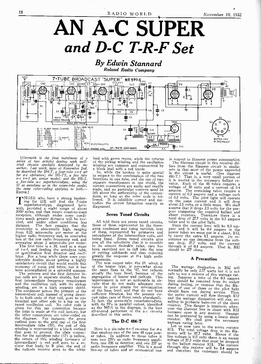
18 RADIO WORLD November 19, 1932
AN A -C SUPERand D -C T -R -F Set
By Edwin StannardRoland Radio Company
7.=TUBE BROADCAST "SUPER" N9. 597-S.F. C.r- 1(175 N.C.) (175 N.C.) C7(56) (57) E LOW
I
I. F. GREEN (58) L F. (57)
voin-E,"RaGREEN -
MARK ,RED TkRoca.
P 10,000 OHMS (TAPER)Ri - 300R2- 350053- 2000R4- 40,000R5- 30,000 WATT)R6- 15,000 )R7- 0.25 MEG.
R9- 0.25255- 1.0
C. Co- .006 PAMCi - 0.1C2.-.002C3 - O. tC4 - 0.5 ..05 - 0.25C6 -.0005C7 -.05 -06 - 0.1C9 - 8 MFC1 - ELECTROLYTICC11- 0.1 s.
G - 3 GANG .000365 MFO.
CS g3
,00.00, 5 xT113
t100)
CP TOOTS WOO MM.
S.Y4C L t
A.G.
Ge
4 kBOTTOM VIEWor (59) SOCKET
[Herewith is the final instalment of aseries of two articles dealing with well-tried circuits specially developed by theauthor. Last week, issue of November 2nd,he described the 594-T, a four -tube t -r -f setfor a -c opiration; the 595 -TS, a five tubea -c t -r -f set, senior model; and the 595-S,a five -tube a -c superheterodyne, using the57 as autodyne as in the seven -tube model,the same color -coding applying to both. -EDITOR.]
THOSE who have a strong hanker-ing for DX will find the 7 -tubesuperheterodyne, diagramed here-
with, provided a night range of about3000 miles, and that means coast -to -coastreception, although under some condi-tions much greater distance will be cov-ered, and under other conditions lessdistance. The fact remains that thesensitivity is abnormally high, rangingfrom 0.25 microvolts per meter at thehigher radio frequency end, to somewhatless at the low radio frequency end, andaveraging about 2 microvolts per meter.
The first tube is a 58, used as a stageof t -r -f, and feeding the autodyne tube,or combination first detector and oscil-lator. For a long while there were con-siderable doubts about getting a highlysatisfactory circuit that would enable thiseconomy of room and tubes, but it hasbene accomplished in a splendid manner.
The antenna and the first detector in-put coils are in separate shields, but thefirst intermediate frequency transformerand the oscillation coil, with its pickupwinding, are in a high separate shield.The condenser across the primary of theintermediate coil, instead of going direct-ly to both ends of that coil, goes to oneterminal and other side to a tap on thetuned oscillation coil, No color code isgiven for this tap connection becausethe joint is made at the coil factory, butthe other connections are color -coded onthe diagram. For instance, the greenoutlead goes to the grid cap of the firstitnermediate tube (58), the end of thiswinding is represented by a black outleadthat goes to ground, the plate connec-tion for the autodyne tube (57) is yellow,the return of this winding (primacy ofintermediate) is red and goes to a re-sistor that leads to B plus, the end ofthe cathode resistor goes to the white
lead with green tracer, while the returnsof the pickup winding and the oscillationwinding are common and represented bya black lead with a red tracer.
So, while the hookup is quite specialin respect to the combination of the twofunctions in one tube, and the use of twoseparate transformers in one shield, thecorrect connections are easily and readilymade, and no particular concern need befelt about the authenticity of the connec-tions, so long as the color code is fol-lowed. It is infallibly correct and em-bodies the circuit formation exactly asdiagramed.
Seven Tuned Circuits
All told there are seven tuned circuits,three of them represented by the three -gang condenser and being variable, fourof them represented by primaries andsecondaries of the intermediate coils, andbeing fixed. Seven tuned circuits giveyou all the selectivity that it is possibleto its utmost desirable value, care hasbeen exercised not to fall into the trapof cutting sidebands and thus reducinggreatly the response at the high audiofrequencies.
The new output tube, the 59, which isof the heater type, is somewhat alongthe same lines as the '47, but reducesgreatly the hum level, because of thesegregation of heater and cathode. Thisimprovement is not so noticeable in cir-cuits that do not make adequate pro-vision in prior stages for minimizationof the hum level, and that do not havesufficient filtration, but the present cir-cuit takes care of those needs abundantly.In fact, the seven -tube superheterodyne,with its 59's in parallel output, identifiedas the 597-S in the diagram, is the bestall-around performer of the a -c circuitsdescribed in this series.
The D -C 486-T
Here is a six -tube t -r -f receiver for d -cthat employs two of the new 48 type pow-er tubes. In addition to these tubes ituses two 239's as radio frequency ampli-fiers, one 236 as detector, and one 237 asaudio frequency amplifier. This is a goodline-up of tubes and an economical one
in respect to filament power consumption.The filament circuit in this receiver dif-
fers from the filament circuit in similarsets in that most of the power expendedin the circuit is useful. (See diagram486-T.) That is, a very small portion ofit is wasted in the necessary ballast re-sistor. Each of the 48 tubes requires avoltage of 30 volts and a current of 0.4ampere. The remaining tubes require acurrent of 0.3 ampere and a voltage eachof 6.3 volts. The pilot light will operateon the same current and it will dropabout 2.5 volts, or a little more. We shallassume that it drops 2.5 volts for the pur-pose computing the required ballast andshunt resistors. Therefore there is atotal drop of 27.7 volts in the 0.3 amperetubes and in the pilot light.
Since the current here will be 0.3 am-pere and it will be 0.4 ampere in thepower tubes we must put in a shunt, R12,to carry the extra 0.1 ampere. Its re-sistance we can determine from the volt-age drop, 27.7 volts, and the currentthrough it of 0.1 ampere. That is, R12should be 277 ohms.
A Precaution
The wattage dissipation in R12 willnormally be only 2.77 watts but it is notsafe to use a resistor of this wattage rat-ing. Suppose a tube of the 0.3 amperetype should be removed from its socketduring testing, or suppose that the fila-ment of one of them or the pilot lightshould burn out during service. Thenthe entire current will flow through R12and the wattage dissipation will rise, re-sulting in probable burn -out of the shuntresistor. This danger is imminent when-ever the filament line in shunt with R12becomes open in any manner. Damagecan be prevented by using a heavy shuntresistor. We shall give the necessarywattage rating later.
Let us now turn to the series resistorR11. The total voltage drop in the fila-ments will be 87.7 volts. Hence if theline voltage is 115 volts there is an excessvoltage of 27.3 volts that must be droppedin the ballast resistor R11. The currentthrough this resistor will be 0.4 ampereand therefore the resistance should be

November 19, 1932 RADIO WORLD 19
SIX TUBE D -C T -R -F SET W° 486-T
AERIAL COntacTioNTO SET
c;_ 239
CL
RI.
CU
CIO
PL
239 236
a
3
C4
R7
CS
C6 232
Tc.f,
4 R5
C7.)R6
Gi, 48
RIO
BOTTOM VIEWOF (48) SOCKET
Gz
Gil 48
R-12
+
wit0Y.DCRB R9
CHASSIS
-4\ GROUND
CONNECTION705E7
MFD.THREE GAHG0.0003651A,D.
C4 0.25 MFO.C5 0.0005 mFO.
CC
56 .0.0 MG..7-8.9-16.04 owl)F.
C17.13- 8MFo-
RS 3 0 0 4.R2 0.0 MEGA.R3 - - - 0.04MEo 454 0.25meo-&R6 0.6 MEG,-R6-8-- - -.0.002 MEGA.R.7- - - - -LME6 A-
R9 - - _ _6026 MEGA.RLO I 70,-R I I _ _ _ _ 68 25WAT7R 12 _ _ _ _ _27 74. !O WATTPL.__ _2,5y.
68 ohms. It is so specified in the list ofparts. The wattage dissipation will be10.9 watts. Hence we should use a re-sistor of about 25 watt rating to have anample margin of safety.
Now we can return to the shunt re-sistance. We have the ballast resistanceof 68 ohms. The resistance in the fila-ments of the two 48 tubes will be 150ohms and the shunt resistance is 277ohms. Hence we have a total of 495ohms in series with 115 volts when the0.3 ampere circuit is open. The currehtthen will be 0232 ampere. At this ratethe power dissipated in R12 will be veryclose to 15 watts. A ten watt resistorwill be safe enough if the open is of shortduration but it would be better to usea 15 or 25 watt resistor for R11. In thelist of parts it is given as 10 watts.
While we have specified R11 and R12at 68 and 277 ohms, respectively, neitheris extremely critical because the filamentcurrent of the tubes is not critical. Afew ohms more or less would make nopractical difference.
Since all the tubes in the circuit are of
the heater type we can use the full volt-age of the line on the plates of all thetubes, except for such voltage as is takenfor the grid bias. The plates and thescreens of the two power tubes are con-nected directly to the positive side of theline so that no voltage is dropped in thefilter choke. This connection is allowablein view of the facts that the line voltageis partly filtered, that the power stage ispush-pull, and that a large condenser isconnected across the line. The effectivevoltage on the plates is only about 100volts, however, because there is a dropof about 17 volts in the bias resistor R10,which has a value of 170 ohms.
While the by-pass condensers C12 andC13 in the B supply circuit are specifiedat 8 mfd. each, 4 mfd. condenser wouldbe all right. Of course, the larger thecapacity the better. It is preferable touse paper dielectric condensers ratherthan electrolytics because with dry con-densers it is not necessary to observe anypolarity.
The speaker used in this set should bespecially designed for the 48 tubes be-
cause the optimum load resistance islower for these tubes than for any otherpower tube. It is only 2,000 ohms pertube. Suitable speakers are now avail-able.
The 48 tube requires a six -contactsocket and the connections are to be madeas shown in the insert at the upper righthand corner of the drawing. It will benoticed that the grid next to the plateon the socket should be connected to thehigh voltage and the grid next to thecathode is to be connected to the highvoltage side of the transformer. That is,G1 is the control grid.
The volume control R2 is a 10,000 ohmpotentionmeter and it should be of thetapered type. The slow rate of changeend of the resistance should be connectedto the antenna. It may be difficult to tellwhich is the slow -tapered end but it canbe discovered experimentally. If the re-sistance is connected in the wrong waythe volume change will be abrupt but ifit is right, the change in volume will begradual. The test should be made on astrong signal.
Fading and Weather ConnectedObservation on radio fading promises
to aid meteorologists in predictingweather conditions, according to con-clusions reached independently by Pro-fessor R. C. Colwell, of the Departmentof Physics of West Virginia University,and Professor Ivo Ranzi, of the Uni-versity of Camerino, Italy.
Although these observers worked inzones of widely different climatic condi-tions and made their observations ondifferent waves their conclusions arepractically identical. Professor Colwellmade his observations on the 309 -meterwave of KDKA, Pittsburgh, and Pro-fessor Ranzi made his on a 100 -meterwave.
Transferred ReflectionBoth observers believe that fading is
due to reflection in the E stratum of theKennelly -Heaviside layer. This is a layerof strongly ionized gas, the ionizationbeing produced by radiation from thesun. When the effect of the sun ceasesabout sun -down the ionization densitydecreases and the reflection is transferred
to the F stratum of the Kennelly -Heavi-side layer, which is higher up.
The two professors have observed thatwhen a cyclone advances from the norththe ionic density of the E stratum greatlydecreases and that when an anticycloneadvances from the north or when a cy-clone exists to the south, ionization in-creases rapidly.
Disturbances at High AltitudesA cyclone is what is usually known
as a general storm. It is characterizedby a whirling motion of air over a widearea, with a low barometric pressure inthe center. On the front the wind isfrom the southwest, in the northernhemisphere, and is accompanied Bycloudiness or precipitation. An anti-cyclone is just the reverse. In the cen-ter the barometric pressure is high, thewinds blow outward, and the weather isclear.
The connection between radio fadingand weather seems to indicate that theair disturbances known as cyclones andanticyclones extend to great altitudes.
Amyl acetate on a wire brush removesfrom radio wire.
enamel
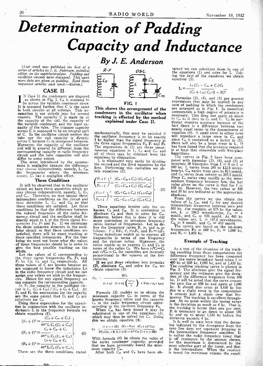
20 RADIO WORLD November 19, 1932
Determination of PaddingCapacity and Inductance
[Last week was published the first of aseries of articles by J. E. Anderson, technicaleditor, on the superheterodyne. Padding andoscillator circuits were discussed. This weekmore data are given on padding. Read theseimportant articles each week.-Emoal
CASE IIIN Case II the condensers are disposed
as shown in Fig. 1. Cm is assumed tobe across the variable condenser alone.
It is assumed further that C is the samein both circuits at all settings. This as-sumption is not strictly true for severalreasons. The capacity C is made up ofthe capacity of the coil, the capacity ofthe variable condenser, and the input ca-pacity of the tube. The trimmer capacityacross C is supposed to be an integral partof C. In the oscillator circuit neither thetube nor the coil capacity is directlyacross C because Cs is interposed between.Moreover, the capacity of the oscillatorcoil will in general be different from thecorresponding capacity in radio frequencycircuit and the tube capacities will alsodiffer to some extent.
The error introduced by the assump-tions is negligible because the differencemay choose independently, namely, L, C.,the frequencies where the minimumcounts, Cs has a negligible effect.
Three ConditionsIt will be observed that in the oscillator
circuit we have three quantities which wemay choose independently, namely, L. Cs,and Co.. Therefore, we may impose threeindependent conditions on the circuit andthen determine L, C., and Cm so thatthese conditions are satisfied. Let theseconditions be that the difference betweenthe natural {regencies of the radio fre-quency circuit and the oscillator shall beexactly equal to f, at the three signal fre-quencies Fo, Fi and F2. If we determinethe three unknown elements in the oscil-lator circuit so that these conditions aresatisfied, there will be exact tracking atthese specified frequencies. For the timebeing we need not know what the valuesof these frequencies should be in order togive the best possible tracking on thewhole.
Let the values of C corresponding tothe three signal frequencies Fo, Fl, andF. be Co, CI, and C2, respectively. Allthese values of C are known because weare supposed to know the inductance Loin the radio frequency circuit and we canassign any values we wish to the frequen-cies. Hence for any signal frequency wecan compute the corresponding capacity.
At F. the capacity in the oscillator cir-cuit is C. (Co + Cm) / (C. + G + Cm). AtF1 and F. the expressions for the capacityare the same except that C1 and C2 aresubstitute for Co.
Using these expressions for the capaci-ties in conjunction with the oscillator in-ductance L in the frequency formula weobtain equations (1).
(C. + Cm + C.)(F. -I- -
48LC.(Co+Cm)C1 + Cm + C.
(Fi + 02-472 L C. (C3. -I- Cm)
C2 ± Cin + CS(F2 + 0 -
472 L C. (C2 + Cm)These are the three conditions stated
(1)
By J. E. AndersonR -F 05G.
FIG. 1This shows the arrangement of thecondensers in the oscillator whentracking is effected by the method
explained under Case II.
mathematically, that must be satisfied ifthe oscillator frequency is to be exactlyf kc higher than the signal frequency atthe three signal frequencies Fo, F2 and F2.The expressions in (1) are three simul-taneous equations in L, C. and Cm andall of these may be obtained from theequations by elimination.
L is eliminated very easily by dividingthe second and the third equations by thefirst. Performing this operation we ob-tain equations (2).
(+ fl2(G. + Cm + C.) (Co +Cm)- =
F. + f (G + Cm + C.) (C2. +Cm)
f l 2(C2+ Cm + C.) (Co +Cm)=Fo+ f (C0+ Cm+ C.) (C.+ Cm)
These equations involve only the un-known C. and Cm. It is convenient toeliminate C. and then to solve for Cm.However, before this is done it is stillmore convenient to introduce frequencyratios instead of frequencies. Let us de-fine the frequency ratios R, r1, and r2 asfollows: f = RFo, F1 =r,Fo, and F2 =These definitions enable us to express allfrequencies in terms of one frequencyand the various ratios. Moreover, theratios enable us to express C2 and C2 interms of the ratios Co. We have r22C2=-Coand r.T.= C., for capacities are inverselyproportional to the squares of the fre-quencies.
If we put these relations into formulas(2), eliminate C., and solve for Cm weobtain equation (3).
Cm =RC.
o- (2)
rri r2(1 + ri) (1 + rs)
2
(3)
+R(ri+ r2+ rirs)
Formula (3) enables us to obtain theminimum capacity Cm in terms of theknown frequency ratios and the capacityC. in the radio frequency circuit corre-sponding to the tie -down frequency Fo.
When C. has been found it may besubstituted in one of the equations (2),
which may then be solved for C.. Doingthis we obtain equation (4).
(i + r, + 2R) (Co + Cm) (Cs + ri2 Cm)Cs - (4)RC. 2ri + R (1 + ri)] - ri2 Cm (1 + + 2R)
With formula (4) be obtain the value ofthe series condenser capacity, providedthat we have previously found the mini-mum capacity Cm.
After both Cm and C. have been ob-
tained we can substitute them in one ofthe equations (1) and solve for L. Tak-ing the first of the equations we obtainequation (5).
(CoIN Cm + COGL - (5)
(C. -I- Cm) C. (1 +
Formulas (3), (4), and (5) are generalexpressions that may be applied to anycase of padding in which the condensersare arranged as in Fig. 1. In numericalcomputation a high degree of accuracy isnecessary. This does not apply so muchto Cm as it does to C. and L. C. in par-ticular requires accuracy because of thefact there is a difference between twonearly equal terms in the denominator ofequation (4). A small error in either termwill introduce a large error in C., andsince C. is contained as a factor in (5),there will also be a large error in L. Ithas been found that the accuracy requiredis at least that obtainable with five -placelogarithms.
The curves in Fig. 2 have been com-puted with formulas (3), (4), and (5) atintervals 50 kilocycles from f = 0 to f =600 kc. L varies from 245 to 122.8 micro -henries, Cm varies from zero to10.1 mmfd.,and C. varies from infinity to 255.5 mmfd.Since C. varies very rapidly as the inter-mediate frequency becomes low, the lastvalue given on the curve is that for f =150 kc. However, the two values at 100and 50 kc are indicated at the appropriateabscissas.
From the curves we can obtain thevalues of L, Cm, and C. for any desiredintermediate frequency between zero and600 kc. For example, at 175 kc the valuesare, L = 190.5 microhenries, Cm = 4mmfd., and C. = 920 mmfd. At 400 kcthe values are, L = 147.5 microhenries,Cm = 8 mmfd., and C. = 410 mmfd.
The curves are based on the tie -downfrequencies Fo = 600 kc, F1 = 1,000 kc,and F2 = 1,450 kc.
Example of Tracking
As a test of the closeness of the track-ing resulting from these computations thedifference frequency has been computedover the entire broadcast band when f =400 kc at 600 kc, 1,000 kc, and at 1,450 kc.The resulting tracking curve is plotted inFig. 3. The abscissas give the signal fre-quency and the ordinates give the devia-tion of the difference frequency from 400kc. It will be noted that the curve crossesthe zero line at 600 kc and again at 1,000kc. It should also cross at 1,450 kc butdue to a slight error in the computationit crosses just a shade over that fre-quency. The tracking i's excellent through-out. At no point within the tuning rangeis the deviation as much as 4 kc. That is,the tracking is better than one per cent.It is necessary to go down to about 540kc and up to about 1,530 kc before thedeviation exceeds 4 kc.
It is well to state here that the detun-ing indicated by the divergence from thezero line does not represent detuning inthe intermediate frequency amplifier. Itis rather the radio frequency tuner thatis off resonance by the amount shown,for the maximum is determined by themost selective part of the tuner, and thatis the intermediate. When the receiveris tuned for maximum volume the result

November 19, 1932 RADIO WORLD 21
as1111111 MINI I
hilili .11 ' I r... ....... .. .......................... . .............. 4 imumuummulimmimmmummin0. I. 11111111111111111MIMIIMIIIIIIIIIMINIIIIIIIIIIM11111111111111111111M1111111111M
MIN M
nilMIIIIIMIN 0
KIN
mom
2 6 0 III Q . ffillilliallii hiliiiIIIIIIIIIMIN
2 2 0
240 11111111FI: ;:k1K-CC 1111101111111
illikk ii " : /2411'C 1111111111111
1111111161111111191111111111,111111111111
2 00. 1111111111111011111011 11111111 I !Fill / °
INEllinhallialliBMIPMFAIIIHINI kL' 8
/ 6 0 I 11111111111111111111111111t11101111111111111111111 I11111111111111111111111111111111
11111111111111111111111/1110111101111111111111111
IIIIIIIIIIIIINNIMPININNIIIIII IMON
1" 1111111111.111illIMIMINIIIIMPIIIIIIIIIMIIIIMMIIMIUIWAIIEIIIIMMIIIMMIIIIIMIIIM 111111111111111M11111111M111.....a.........................................IIIIMIIIIIIIIIMIIIVAIMIIIMIIMMIIIIIMMIIMMINIIIIM1111111MIIIIMIIIIIMIIIIVAMIIMIIIIIMIMIIMINIMMIIIMENIIMIIIIMUmmIIIIIIMMIIIMIIMMIIIIMIIIIIIIIERIMMIMIIIIIIIIMMIllailk.
..,,....,...,9,...............,...........AIWA IIIIIIMINAMMIAMINEMIIIIMIIMINE 1111111511111MWirninnlnualffinuri . Nur miniiirim urnammumimmomm MEM ma
600 /00 200 300 400 sop1,vriRkapmrE FREQUENCY (KC)
FIG. 2These curves give the minimum capacity Cm, the series capacity Cs, and the oscillator inductance L for variousintermediate frequencies between zero and 600 kc. Values are based on an inductance of 245 microhenries in
the radio frequency circuit.
1/00
/004
900
/2 800
700
600 6)
6 500
4 400
2 300
200
is really a compromise between the twotuners so that actually both are detuned,in opposite directions, but the intermedi-ate has by far the greater influence be-cause it has the greater relative selectiv-ity.
Even if all the detuning should occurin the radio frequency amplifier the per-centage of detuning is small. Suppose itamounts to 4 kc as in this case. At 550kc this would amount to about 0.7 nercent. of the signal frequency and at 1,500kc it would amount to only about 1/4 ofone per cent.
It was stated previously that the point of
of inflection of the tracking curve, that is,the point where the curvature changesdirection, should fall below the zero lineby a small amount. The encircled pointin Fig. 3 is that point, and it falls just alittle below the zero line. It will be noted,however, that at 750 kc the deviation isgreater than it is at 1,250 kc. A slight im-provement, therefore, could have beenmade in the tracking if F1 had beenchosen slightly below 1,000 kc rather thanexactly 1,000 kc. The point of inflectionwould then have been closer to the zeroline and the curve would have been morenearly symmetrical. The difference is so
slight, however, that it was not consideredworth while to select a lower value forF1 in view of the simplicity of computa-tion with 1,000 kc.
We mentioned the possibility of findingthe frequency at which the point of in-flection occurs. The point may be foundas soon as C. and C. have been found,for the relation determining it is C = C.[1 (4 -I- 3C. / C.)1/41. The frequencyis obtained from C thus determined andfrom the inductance Lo in the radio fre-quency circuit. Sometimes the relation isuseful in estimating the closeness of thetracking. (Continued next week)

22 RADIO WORLD November 19, 1932
Radio Universityj QUESTION and Answer Department. Only questions from Radio Uni-A7 versity members are answered. Such membership is obtained bysending subscription order direct to RADIO WORLD for one year (52 issues)at $6, without any other premium.
RADIO WORLD, 145 WEST 45th STREET, NEW YORK, N. Y.
VARIOUS circuits I have built, re-quiring an oscillator, have included themodification of the Hartley, as developedby Shiepe, and as first shown in yourcolumns. That it is an excellent anddependable oscillator there is no doubt.Now I am ready to try my hand at ashort-wave super, but it musn't consistof more than five tubes. Therefore themodulator is also the oscillator. I havetried various methods of obtaining thesignal input, but find that it has to beto the control grid circuit, otherwise nextto nothing doing. That leaves me upa tree as to the oscillation combination,and I don't want to give up this excel-lent oscillator. A few helpful sugges-tions will be appreciated.-C. J.
The circuit is shown in its entiretyherewith, and those experimentally in-clined my try their luck with this auto -dyne. After the autodyne, of course,everything is. more or less standard, andno experimentation is necessary. Thecircuit .shows a coil switching system.The grid to the left, in the 57, is thecontrol grid, and into this the signal isput. The oscillation circuit is the sup-pressor grid, which may be returned tothe taps on the coils or to cathode itself,as you prefer. The desire is to have asmuch signal input as practical, and aslow an oscillation voltage as is consistentwith adequate mixing. The two circuits-control grid and suppressor grid-arebut loosely united, so far as electron flowis concerned, and therefore the two dif-ferent frequencies are combined in thesame tube by electron coupling. Thereis no reason, so far as we can see, thatthe oscillator should not work as shown,although this particular feature (of os-cillation in the suppressor circuit) isnovel and experimental, and we makeno claims for it nor any guarantees ofany kind. We do say it is well worthtrying, as some engineers of standinghave obtained results that way. Someother experimenters have failed.
20 000e- Niro 0.000225WC,
On Cr.
0.0sMot
0.0 M02FD
0.04MA
HAVING BUILT the 4 -tube a -c 1933Diamond of the Air, I am suffering thefollowing troubles: (1) Sensitivity is notas high as I expected; (2) there is atunable hum, in that the hum is greatestat maximum volume position of the vol-ume control, and least at minimum posi-tion; (3) the set squeals, and I don'tknow just what to do to stop it; (4) thepentode plate current is not around 38milliamperes but around 63. A little helpis needed.-L. V. G.
Answering your questions in their or-der: (1) Low sensitivity may be due toso many causes in any set that it is notpossible to locate the exact trouble fromthe information given, but since you en-counter squealing it is obvious that thetuner itself is keenly alive and that thereis some defect in subsequent coupling.Whenever a set squeals it is at least agood sign that there's plenty of life. Get-ting rid of squealing is not difficult.(2) What you refer to as tunable humis not that at all, for tunable hum hasto do with hum heard when tuning ina station, and not heard when no stationis tuned in, hence has nothing to dowith the volume control. Your troubleevidently. is (a) that the detector tubegets no plate current, because cathodereturn is open, or no B voltage is ap-plied; (b) no voltage on screen; or (c)resistor between cathode of detector andcathode of r -f is too low, so try a re-sistance of 10,000 ohms. (3) Squealingmay be cured by removing turns fromprimary of interstage coupler, or by put-ting a resistor across antenna -groundposts, of such value as stops the squeal-ing, but not of any lower value thannecessary; or instead a resistor acrossdetector tuned circuit, where around20,000 ohms may be tried. (4) the highplate current is commonly due to thewrong bias on the power tube, which inturn may result from a defect in thepower tube itself. Usually, however, itis because of the wrong value in the
4500C
0.15MA
5o.
450 kr.
bias -apportioning resistors for the pen-tode tube. Carbon resistors, by the way,do not stay put enough to be serviceablein this position. Put a 0-100 or 0-50milliammeter in the plate circuit of theoutput tube and put in higher resistancevalues between joint of the two biasingresistors and ground until the plate cur-rent does not exceed ma in this circuit.You did not mention it, but if the platecurrent runs that high, then the maxi-mum voltage must be down to about200 volts. It is quite likely you failed toinsulate the first 8 mfd., next to rectifier,and that is the full cause of all yourtroubles. When you have corrected thedefects as stated you will have an ex-tremely delightful little receiver.
* * *
SOME TIME this Winter I intendto build a television receiver and wouldlike a few hints on (1) what kind ofa tuner to use; (2) what kind of audio;(3) whether the output tube or tubesshould be of the heavy or light platecurrent types. I amn prepared to go upto 400 ma if you say the word.-L. E. T.(1) You do not say how far from thereception points are the stations to bebrought in, but if you are not close tothem, build a superheterodyne consistingof a simple mixer, two stages of i-f withvery tight coupling between plate andgrid circuits, using additional condensersfrom plate to grid if standard coils areused; full -wave 55 second detector. triodeunit as a stage of resistance audio, anduse an output tube that under normalreceiver operating conditions would drawplate current about three times the maxi-mum current recommended for the neonlamp. Don't forget to have the scan-ning system the best that is obtainable.
* * *
WHAT IS the object of having a lowresistance B choke for better regulationwhen the high -voltage secondary of thepower transformer, through which thesame current flows, has a high resistance?-E. J. N.
No object consistent with good prac-tice. While in the case stated the totalresistance is lower than it would be ifthe choke were of high resistance, stillthe purpose is defeated when the powertransformer secondary has a high re-sistance. About the best recommenda-tion to make under the circumstances,supposing the power transformer re-mains, is to introduce a heavy bleeder.
* * *
WHAT IS a good type of broadcasthookup for single tube mixing?-A. L.See Edwin Stannard's hookup on page18.
0.01.cro 55
0.00
II
rlHa0005
0.1501^
500A
TMREr0.4 FD.
0.02MA
THREE
0.im," 4 000
140 NO
0.55
I1
80
SW...prarrn
FIG. 1037Design of a five -tube superheterodyne, wherein the first 57 is used in autodyne fashion, and an experimentalmethod shown for separation of the signal and oscillation inputs.

November 19, 1932 RADIO WORLD 23
STATION SPARKSBy Alice Remsen
WanderlustFor "Savannah Liners"WJZ Tuesdays, 6:30 p.m.
Roaming the byways of the world,Healthy, and broke, and free;
Knowing the feel of a heather couch,Knowing the smell of the sea.
Tramping the cobbles of Amsterdam,.Coaling a ship at Rangoon,
Making love to a brown skinned lass,Under a tropical moon.
Scrubbing the decks of a P and O,Mediterranean bound;
Wandering through a thousand ports,Covering plenty of ground.
Treading the streets of London town,Drinking beer in a pub;
Knowing the fear of a cornered rat,First time down in a sub.
Owning a pair of feet that itchEach time they stop for a while;
Owning a soul which longs for rest,-Away on a lonely isle.
Longing to stop, yet bound to go,Through storm, or fire, or flood.
What is a sailor -man to doWith wanderlust in his blood!
-A. R.* * *
AND IF YOU LISTEN IN TO THESAVANNAH LINERS PROGRAM tin-der the direction of Bob Armbruster,you'll get wanderlust and want to gowandering around the world in ships.Listen in; you'll like it!
* * *
The Radio RialtoIndian summer is with us, so we shan't
mind our rambles today. . . . The oldrialto is flooded with sunshine . . . there'sa pleasant tang in the air which seems togive zest to what ever we do. . . In spiteof the vague whispering campaign nowgoing the rounds as to what may happenif so-and-so, or so-and-so gets in, therialto ramblers are in an optimistic mood.. . . We meet Bob Haring, the well-known orchestra leader, at the corner of47th and Broadway. Bob hasn't had aprogram for weeks, but he's still grinning,still smoking a cigar, and still optimisticfor the future. Great guy, Bob ! . . .
There's Harold Van Emburgh, the singingsaxophonist, carrying a music case weigh-ing thirty-five pounds. Harold was heardon the air plenty last year, with Rolfe'sLucky Strike program and the Club Val -spar, but this year he's had no luck; hehas just opened at the fashionable nightclub, the Place Pigalle, where he singsand plays until the wee sma' hours, buthe doesn't grumble, for he has a wife andbaby to take care of; but Harold is veryoptimistic today; says he thinks thingswill pick up after election. Let's hope so.
There's Irving Berlin, a dapper littleman; we say "hello" and tell him he's get-ting fat. We're quite close to his musicemporium, so supposing we stop up andsee Georgie Joy. . . . Well, well! Whaton earth has happened to you, Georgie?There the poor lad sits behind his desk,his arm in a sling, and we find out thathe thought he would like to join FrankParker's polo club, and took a ride on ahorse; the horse didn't like it, cut uprough, threw him off, and left Georgiewith a broken shoulder; but even withthat handicap, Georgie, like everyone elsewe have met today, is smiling. . . . LittleBenny Bloom, Irving Berlin's publicity
man, is in the same mood, grinning fromear to ear. Gee, what a wonderful worldit is today! . . .
WLW, Cincinnati's wonderful station,has sent representatives in to New Yorkto search for radio talent. We had theprivilege of meeting their Mr. Nichols, acharming English gentleman, and Mr.Perazz, equally charming and courteous ;these gentlemen have listened to .hundredsof radio artists and would-be radio artistsduring their short stay at the Hotel NewYorker ; they have not yet decided on thelucky one . . . they are in the market fora girl who can sing torch songs, balladsand rhythm numbers . . . it will be a verypleasant engagement. . . . Ran into MollyKlinger up there, and she was obliging asusual, playing for some of the singers....June Pursell and Billie Dauscha wereamong those heard....
Well, let's toddle up to Feist's. . . .
Johnny White, the professional managerand my very good friend, lost his dearold dad a few days ago and is feelingpretty blue. Buck up Johnny lad l . . .
Sitting with Johnny is that clever leader,Joe Furst, who conducts the smoothrhythmic band heard over WABC andemanating from the Village Barn. JoeFurst is a nice fellow and a good musician,tells us that he has a harp in his band,and also invites us down to the VillageBarn to give it the once over; we hear itis an unique place, so we'll go one ofthese fine nights and then perhaps tellyou all about it. . . . There's handsomeJim Brennan, who, together with BillHansen and Howard Howe, makes up thetrio known as the Three Little Sachs; hetells me they are back on the air overWMCA; this is good news, for theywere always a snappy and entertainingtrio. . . . A little farther up Broadway isthe WMCA building in which HowardLanin has his office; we haven't seenHoward since the Bourjois summer pro-gram went off the air, so let us gallivantup to the seventh floor and say "Hello.". . . The office is humming with activity.Jimmy Lanin greets us with a smile andushers us into the private office of thejovial maestro, Howard. . . . He's pleasedto see us ; we sit down and chat, andlearn that the boys are all excited be-cause a protege of theirs, one Jose San-tiago -Font, has become the primo-bassoof the Scala Milano.. . . While under themanagement of the Lanin Brothers, hewon the Caruso Memorial prize and es-tablished a precedent by winning a re-newal of the scholarship for an extrayear. During his first year in Italy hechanged his voice from a baritone to abasso-profundo. . . . We also learn thatHoward Lanin now has a mixed quartettefor his family, two boys and two girls; thelast little girl was born on October 3rd.. . . Met up with Tommy Weir, of theswell tenor voice; we both worked on theEnglish synchronization of a German filmat the Standard Sound Studios; he's nonethe worse for his ferry trip twice a dayto and from Staten Island; in fact, I thinkit does him good. . . . Ivy Scott lives overthere too and likes it. - . Ivy, by the way,is in the new musical produced by PeggyFears. . . .
Well, we'll taxi over to WABC and lookaround. . . .Here we are .- . . 22nd flooragain. . . . Righ off the reel we learn 'thata new series of dramatic programs arenow being heard daily at 7:15 p.m., withthe exception of Saturday and Sunday ;called "Buck Rogers in the year 2432."Highlyimaginative series; better listen inand find out what may be happening five
hundreds years from now.. . . Also, theFitch Professor has returned to CBS, withthe Three Brothers Trio, and Helen Mors,platinum -haired torch singer; Wednesdaysat 11:30 a.m. . . . An optimistic tone per-vades CBS also. . . . Perhaps there issomething in the air. . Maybe pros-perity is tired of hiding just around thecorner and has decided to come right outin the open; certainly sounds like it.
Well, we'll meander over to NBC andsee how they feel about it.... Caine alongnow, step out smartly, over to Fifth Ave-nue and don't linger by the way to lookat all the pretties in the shops. . Yes,I know window-shopping is fascinating,but our time is limited, so eyes front, for-ward march. . . . Here we are at 711....Let's take a look in some of the studios.
. Studio A on the 13th floor.... There'sHugo Mariani, rehearsing his orchestra;he always sits on a titlted chair on top ofa little platform, and while he is directingyou always expect to see him fall over,but he's got a wonderful sense of balance.. . . There's Kelvin Keech at the micro-phone; watch him, he smiles, standing ontiptoe, not because he's so short; just ahabit, that's all. . . and there's RobertSimmons, with his eyes glued to theclock; he always watches it while hesings. . . . NOt much news around here.. . . Of course yOU know that Eddie Can-tor is back on the air with Rubinoff forthe Chase and Sanborn Sunday programs.. . . Oh, by the way; I nearly forgot avery interesting bit of information; myold pal, Arthur Behim, is on the air now,every morning except Sunday, with BudCollyer, for Kruschen Salts, 7.45WABC. . . . Listen in to this program asyou eat your breakfast ; it'll put you rightfor the day. . . . And another thing; Igave an audition myself for StationWLW; came to terms with their affablemanager, Mr. Clark, and I leave thisweek for Cincinnati. . . . Shall let youknow time and day of programs and hopeyou'll listen in to your girl friend. . . .WLW is a big station, 50,000 watts, whichwill soon be changed to 500,000 watts, soyou won't be able to miss me. . . . It'sabout time to be on my way home toOctavia's roast beef and Yorkshire pud-ding, and the next time you hear from meI'll probably be on my way to Cincy anda new environment.
* * *
ANSWERS TO CORRSPONDENTSM. Ivkovich, Powhattan Point, Ohio.
. . . Glad you like Stations Sparks; "Myrtand Marge," are mother and daughter.. . . "Myrt" is Myrtle Vail, who marriedGeorge J. Dameral, the original Princein The Merry Widow; "Marge" is DonnaDameral, their daughter. . . . Tito Guitaris from Mexico. Studied at the MexicanNational University in Mexico City..Studied voice in Italy. Came to NewYork in 1929 to make records of Spanishand Mexican songs. Signed with CBSin 1930. . . . Arthur Tracy was born inPhiladelphia. . . . Played small time vau-deville. . . . Was discovered for big timeradio by Eddie Wolfe, who built him upinto "The Street Singer" you know today.Tracy had some experience in dramaticstock and opera before tackling radio... .Harry Richman spent his boyhood inCincinnati. Began his career in Chicago,as piano player in a music factory (songpublishers). Went into vaudeville with aviolinist. Act flopped. Then played pianofor Mae West; ditto the Dolly Sisters.Had a lot .of bumps until the late FloZiegfeld booked him for the MidnightFrolics ; this made him and he has neverlooked back. Has written quite a fewbest selling popular songs.
A. E. M., Albany, N. Y.-Am sorry;have no data at present on Richard Max-well, except that he wears a Phi BetaKappa key. Shall probably get some in-formation about him for you in the nearfuture.

RADIO WORLD November 19, 193?
RADIO KNIFEFREEDandy two -bladedradio knife, one-third larger than il-lustrated, excellentfor cutting wire toNo. 20 with "onepull" and for scrap-ing off insulation.A general utilityknife, too. Send $1for 8 weeks trialsubscription (regularprice); get this knifefree. If already asubscriber, 8 weekswill be added toYour subscription.
RADIO WORLD145 WEST 45th STREET NEW YORK CITY
TWO -SPEED MOTOR33-1/3 and 78 revolutions per minute. Press alever to change from one to the ether.Green Flyer Motor $10.85Direct Radio Co., 143 W. 45th St., N. Y City
BOOKS AT A PRICE"The Superheterodyne," by J. E. Anderson and
Herman Bernard. A treatise on the theory andpractice of the outstanding circuit of the day.Special problems of euperheterodynes treated au-thoritatively. Per copy. (Cat. AB-SH), postpaid -50e
"Foothold on Radio," by Anderson and Bernard. Asimple and elementary exposition of how broad-casting is conducted, with some receiver circuitsand an explanation of their functioning. (Cat.AB-FH), postpaid 25e
Guaranty Radio Goods Co., 145 W. 45th St., N. Y. city
WAFER SOCKETS6/32 mounting holes, 1-11/16 inches apart;central socket hole recommended, 134 inches,although lyi inches may be used.UX, with insulator 100UY, with insulator 10cSix -pin, with insulator lieSeven -pin, with insulator 12c
DIRECT RADIO CO.145 WEST 45th STREET, N. Y. CITY
"FORD MODEL -'A' Car and 'AA' Truck,' oyPage. $2.50. Radio World, 145 W. 45th St., N. Y. C.
ANALYZERPlugs and AdaptersRECEIVER
END964 D5460770n, 6 ToP
906 IN CC
965055- Born:we-Top
967 SS7 -BOTTOM, 6-70P
906-WLC--Finest Analyzer Plug, smaller diameter thanthat of smallest tube, so fits into tightest places in re-ceivers. Seven -lead 5 -ft. cable, six -pin base with studsocket at bottom center. Two grid caps Interconnected (usehandier one), and they also connect with stud socket, whichis a latch lock, and with seventh cable lead, and with con-trol grid of 7 -pin tubes. Adapters (at right) all have sixhole tops to receive Analyzer plug base, and have projectingstud that connects to Analyzer plug's stud socket. Latchin Analyzer Plug base grips adapter studs so adapter isalways pulled out with Analyzer Plug (adapter can't stickin set socket). Pressing latch lever at hottom of Analyzerplug releases adapter $3.23
964 DS -Six -hole top, with stud, four -pin bottom .73965 DS -Six -hole top with stud, Eve -pin bottom .73967 SS -Six -hole top with stud, seven -pin bottom .73
The four devices described above enable access to allUX, UY, six -pin and seven -pin tube sockets in receivers.Additional adapters for all unusual tubes are obtainable.Write your requirements.
On the analyzer there must be socketANALYZERaccommodation for the tube removed
from receiver. One universal socketand one adapter permit putting allUX, UY, six -pin and seven -Din tubesin Analyzer.
456 is a 9 -hole "universal" socket into which will fit,with automatically errorless connection, any UX, UY orsix -pin tube $ .62976 -SL. To enable putting 7 -pin tubes into the uni-
versal socket, an adapter with seven -hole top and six -pinbottom is used. A 6 -inch lead with phone tip is eyelotedto the side. A pin jack on Analyzer, connected to seventhlead of 906-WLC cable, picks up control grid of 7 -pintube through the eyeletted lead $ .73
Additional adapters for all unusual tubes are obtainable.Write your requirements.
437-E. Those preferring two different sockets (universaland a separate 7 -hole socket) rather than one socket andan adapter, may obtain a 7 -hole socket to match the uni-versal in size and mounting holes $ .62
END
MULTIPLE SWITCH2NS9-K-P9. For switching to nine different positions,
enabling current, voltage and other readings. Any oneposition opens a circuit and closes another. Thus theopener, ny interruption, gives access to plate, cathode. etc.,earls, for current readings, while the closer puts the cur-ent meter in the otherwise open circuit. Switch has de -
tent for "snappy" action $2.65
JUNIOR OUTFITFor Receiver End
7 -pin plain analyzer plug, 7 -lead cable attached(977) $1.25
Three adapters for UX, UY and 6 -Din sockets inreceiver (976, 975, 974) 2.19
DIRECT RADIO CO.145 West 45th Street, New York City
BLUEPRINTS OF8 -TUBE AUTO SET
Sensitivity of 10 microvolts per meter charac-terizes the 8 -tube auto receiver designed byJ. E. Anderson, technical editor of RadioWorld, and therefore stations come in withonly six feet of wire for aerial, and withoutground. Mont cars will afford greater aerialpickup, and besides the car chassis will beused as ground, so with this receiver you willget results. The blueprint for construction ofthis set covers all details, including directionsfor cars with negative A or positive Agrounded. The circuit features are: (1) highsensitivity , (2), tones through powerful localsand gets DX stations, 10 kc either side; (3),Latest tubes, two 239 pentode r -f, two 236 screengrid, two 237 and two 238; push-pull pentodes,all of 6 -volt automotive series; (4), remotetuning and volume control on steering post,plus automatic volume control due to lowscreen voltage on first detector; (5), runningboard aerial. The best car set we've published.This circuit was selected as the most highlyprized after tests made on several and is anoutstanding design by a recognized authority.Send for Blueprint 631, ft Situ
SHORT-WAVE CONVERTERIf you want to build a short-wave converterthat costs only a very few dollars, yet givesgood results, furnishing all its own power from110 volts a -c, and uses no plug-in coils, voucan do so from Blueprint 630. Price 1Se
STAR CIRCUITS5 -TUBE AC, T -R -F
Five -tube a -c receivers, using variablemu r -f, power detector, pentode out-put and 280 rectifier, are not all alikeby any means. Forty circuits werecarefully tested and one selected asfar superior to the others. This prizedcircuit was the 627, and if you builtit, you will always be glad you fol-lowed our authentic Blueprint, No.627. This is the best 5 -tube a -c t -r -fbroadcast circuit we have ever pub-lished. Price 21.
A -C ALL -WAVE SETAn all -wave set is admittedly whatmany persons want, and we have acircuit that gives excellent broadcastresults, and is pretty good (not great)on short waves. No plug-in coilsused. Cost of parts is low. Send forBlueprint, No. 628-B, @ 25c.In preparation, an 8 -tube broadcast super-keteroelyne.for 110v d -c. Write for particulars.
RADIO WORLD, 145 West 45th Street, New York, N. Y.
SPEAKERHEADQUARTERS!
F your dynamic speaker suffers lost insensitivityIor develops rattling or buzzing sounds, it usually
needs a new cone and voice coil. We have theunit cone -and -voice -coil assemblies for all thepopular speakers, some listed below. Others areavailable. Inquire for prices.
Service men can make the cone and voice coilreplacements but any who desire that the instal-lation and adjustment be made for them onprecision jigs, in the same manner as in thespeaker factories, may send their speakers to usfor repair. There is a 75c extra charge for thislabor.
The name of the speaker is listed under thecaption, "Speaker," the outside diameter in inchesof the frame that holds the cone is given underthe initials "O.D.," and the price of cone -voicecoil combination unit is given next.Speaker O.D. PriesAtwater Kent 11 $2.75Bosch 11 2.75Bosch 10 1.90Brunswick D 944 2/5Brunswick B 1434 2.75Brunswick E 14% 2.75Colonial. 33 12% 2.25Decatur 91/2 1.90Eveready 1254 2.25Eveready 10 1.90Earl Inductor 10 .95Farrand 7 2.25Farrand
Inductor 11 1.35First Nat'l 10 1.90Freed-Eismann
NR 80-87 10 2.75Majestic Gl 9 1.80Majestic G2 9 1.80Majestic G3 11 1.80Majestic G5 14 2,75Jensen
D9, D15 81/4 1.50D4 9% 2.2.5D7 Concert 1134 2.25Auditorium 13 4.50
Magnavox 9 2.25Newcomb -
Hawley 9 2.25Oxford 9 1.95Oxford 8;4 2.25Peerless
copper coil. 854
Speaker O.D. PricePeerless
copper coil. log 1.95copper coil. 12 2.10copper coil. 14% 2.85
Peerless wire -wound coil. 8%wound coil. 1034wound coil. 14%
Philco 65-90 11Philco 20RCA 106 1054RCA 105RCA 104 SSymington 10Symington 1254Sterling 9Stromberg-
Carlson 12% 2.75Carlson 9 2.25
Sparton 737 9 2.25Steinite 10 1.90Temple 9 2.75Temple 11 2.75Temple
Auditorium 14 3,75Utah 9 1.90Utah Stadium 12 2.75Victor
RE32-45 9 1..35Wright -
De Costa 10 2.25De Costa 12 2.75
1.60 Zenith 52.... 1254 2.25
2.851.652.751.501,502.002.002.001.902.252.25
MAGNETIC SPEAKERSReady to Play, but Not Including Cabinet or BaffleFarrand 9" O.D., burtex cone $1.50Timmons (as used in Philco sets) 9" O.D ,
burtex cone $1.80Auto speaker, 9" O.D., burtex cone $1.50
DIRECT RADIO CO.143 West 45th Street
New York, N. Y.
THREE -IN -ONETESTER FREE!
EVERYBODY who does any radio workwhatsoever, whether for fun or for pay
or for both, needs a continuity tester, so hecan discover opens or shorts when testing.
A mere continuity tester is all right, but -Often it is desired
to determine the re-sistance value of aunit, to determine ifit is correct, or tomeasure a low volt-age, and then a con-tinuity tester thatis also a direct -read-ing ohmmeter anda DC oltnitrcomes in triplyhandy.
So here is the combination of all three:A 0 -454 -volt DC voltmeter, a 0 -10,00S -oho)hnimeter and a continuity tester. A rheinstat is built in for correct zero resistanceadjustment or maximum voltage adjustment.The unit contains a three -cell flashlightbattery. Supplied with two 5 -foot- longwire leads with tip plugs. Case is 4-inckdiameter baked enamel. Weight, 1 lb.Sent you with an order for one year'ssubscription for RADIO WORLD (51weeks) at the regular rate of $6. OrderCat. PR -500. Use Coupon below.
Radio Wadi, 145 W. 45th Street, New York. N. Y.Enclosed please find $6 for one year's subscrip.
tion for Radio World (one copy a week, 52 issues).Send Cat. PR -500 as premium.NameAddress
City State