Embed Size (px)
Citation preview
NGRM700_D00292_03_D_XXEN/07.2019
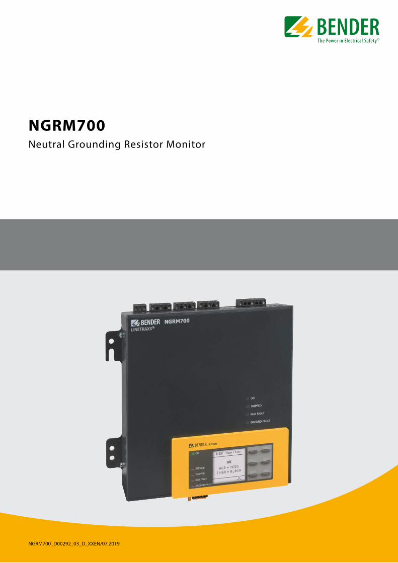
NGRM700 Neutral Grounding Resistor Monitor
2 NGRM700_D00292_03_D_XXEN/07.2019
Product descriptionThe NGRM700 is only intended for use in high-resistance grounded systems. In these systems, the NGRM700 monitors
• the current through the neutral-grounding resistor (NGR),
• the voltage between the star point of the transformer and earth (voltage drop across the NGR),
• the condition of the NGR,
• line-to-line and line-to-earth voltages.
i Systems with a high-resistance grounded star point can be used when an interruption of the power supply would involve excessive costs due to production stoppage (e.g. automotive production, chemical industry). The ground fault that occurs between a phase and earth does not lead to a failure of the power supply in these systems. A ground fault must be detected and eliminated as quickly as possible, since the occurrence of another ground fault in a second phase would lead to a tripping of the overcurrent protective device.
In order to meet the requirements of applicable standards, the equipment must be adjusted to local equipment and operating conditions by means of customised parameter settings. Please heed the limits of the range of application indicated in the technical data.
Any other use than that described in this manual is regarded as improper. Intended use includes following all the instructions in the operating manual.
FunctionThe NGRM700 monitors NGR resistance RNGR, neutral voltage UNGR and current INGR. NGR resistance is monitored using an active and a passive procedure:
active The device generates an active test pulse and measures RNGR even if the installation is de-energised.
passive Only for energised installations: The resistance RNGR is determined when INGR or UNGR exceeds an internal threshold. The device measures the existing current and voltage and calculates RNGR.
In the case of the “auto” method, monitoring switches automatically between “active” and “passive” when the measured value exceeds or falls below the internal threshold.
The threshold is 15 % of the nominal value and can be adjusted by Bender service if re-quired. A short circuit or interruption of the NGR is reliably detected in an energised as well as a de-energised installation with the active measurement method.
When the “passive” method is selected, no switching of the monitoring takes place. No monitoring of the NGR occurs while the installation is de-energised.
The NGR relay switches from alarm state to operating state when the measured resist-ance RNGR is within the configured thresholds.
A ground fault is signalled via the corresponding ground-fault relay when INGR or UNGR exceeds the selectable thresholds. After the adjustable delay time has elapsed, the instal-lation can be shut down by means of the trip relay.
A connection to installations ranging from 400 V…25 kV is possible via the appropriate CD-series coupling device. The INGR is measured via (universal) measuring current transformers for 5 A or 50 mA secondary. With the conversion ratio of the used measuring current transformer the current measurement is internally set in such a way that it adjusts best to INGR.
The phase-voltage monitoring function can be used to indicate which phase has the ground fault. Direct coupling is possible up to a system voltage of 690 V. For higher volt-ages use potential transformers (PT). The conversion ratio is adjustable.
Certifications
NGRM700 Neutral Grounding Resistor Monitor
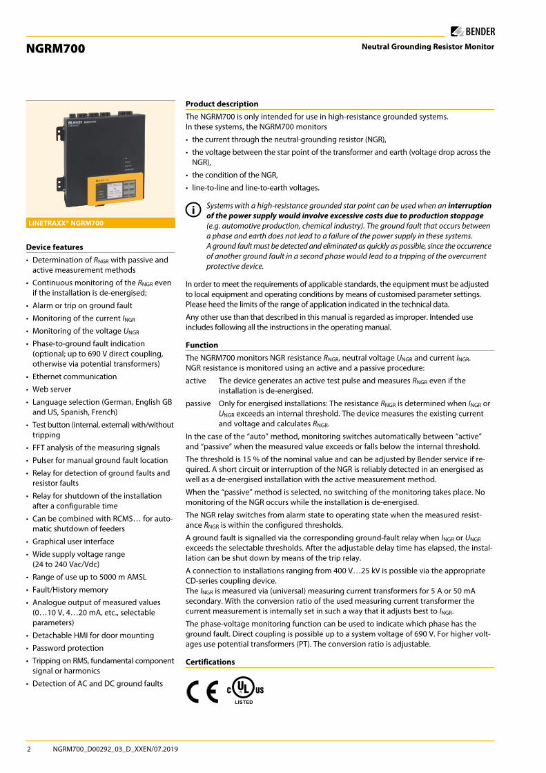
LINETRAXX® NGRM700
Device features• Determination of RNGR with passive and
active measurement methods
• Continuous monitoring of the RNGR even if the installation is de-energised;
• Alarm or trip on ground fault
• Monitoring of the current INGR
• Monitoring of the voltage UNGR
• Phase-to-ground fault indication (optional; up to 690 V direct coupling, otherwise via potential transformers)
• Ethernet communication
• Web server
• Language selection (German, English GB and US, Spanish, French)
• Test button (internal, external) with/without tripping
• FFT analysis of the measuring signals
• Pulser for manual ground fault location
• Relay for detection of ground faults and resistor faults
• Relay for shutdown of the installation after a configurable time
• Can be combined with RCMS… for auto-matic shutdown of feeders
• Graphical user interface
• Wide supply voltage range (24 to 240 Vac/Vdc)
• Range of use up to 5000 m AMSL
• Fault/History memory
• Analogue output of measured values (0…10 V, 4…20 mA, etc., selectable parameters)
• Detachable HMI for door mounting
• Password protection
• Tripping on RMS, fundamental component signal or harmonics
• Detection of AC and DC ground faults
NGRM700_D00292_03_D_XXEN/07.2019 3
NGR monitor NGRM
SERVICE
TRIPPED
NGR FAULT
GROUND FAULT
ON MENU
RESET
DATAINFO
*<
<
<
<
OK
ESC
TEST
FP200
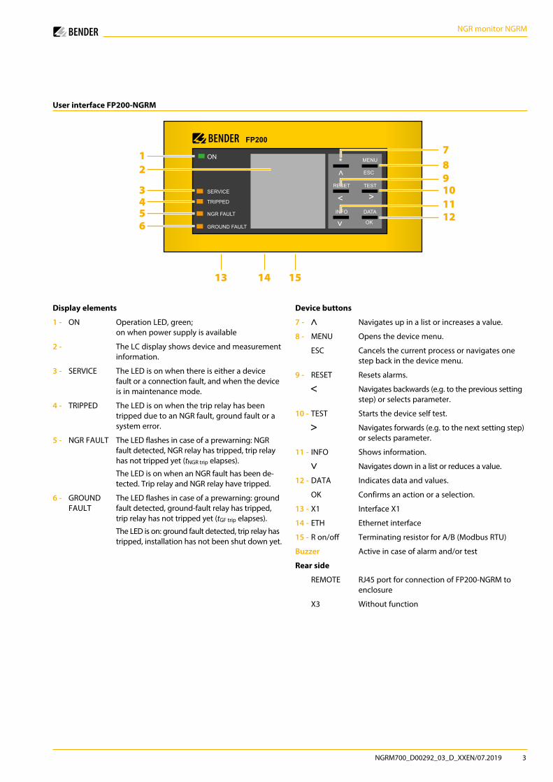
User interface FP200-NGRM
1 7
39
4101112
13 14 15
56
2 8
Display elements
1 - ON Operation LED, green; on when power supply is available
2 - The LC display shows device and measurement information.
3 - SERVICE The LED is on when there is either a device fault or a connection fault, and when the device is in maintenance mode.
4 - TRIPPED The LED is on when the trip relay has been tripped due to an NGR fault, ground fault or a system error.
5 - NGR FAULT The LED flashes in case of a prewarning: NGR fault detected, NGR relay has tripped, trip relay has not tripped yet (tNGR trip elapses).
The LED is on when an NGR fault has been de-tected. Trip relay and NGR relay have tripped.
6 - GROUND FAULT
The LED flashes in case of a prewarning: ground fault detected, ground-fault relay has tripped, trip relay has not tripped yet (tGF trip elapses).
The LED is on: ground fault detected, trip relay has tripped, installation has not been shut down yet.
Device buttons
7 - Navigates up in a list or increases a value.
8 - MENU Opens the device menu.
ESC Cancels the current process or navigates one step back in the device menu.
9 - RESET Resets alarms.
Navigates backwards (e.g. to the previous setting step) or selects parameter.
10 - TEST Starts the device self test.
Navigates forwards (e.g. to the next setting step) or selects parameter.
11 - INFO Shows information.
Navigates down in a list or reduces a value.
12 - DATA Indicates data and values.
OK Confirms an action or a selection.
13 - X1 Interface X1
14 - ETH Ethernet interface
15 - R on/off Terminating resistor for A/B (Modbus RTU)
Buzzer Active in case of alarm and/or test
Rear side
REMOTE RJ45 port for connection of FP200-NGRM to enclosure
X3 Without function
4 NGRM700_D00292_03_D_XXEN/07.2019
NGR monitor NGRM
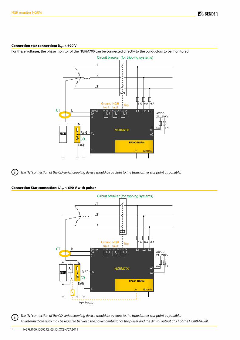
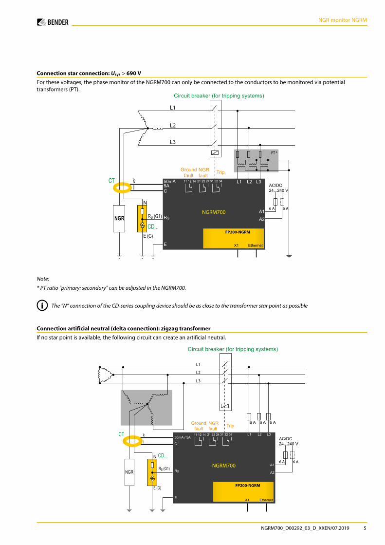
Connection star connection: Usys ≤ 690 VFor these voltages, the phase monitor of the NGRM700 can be connected directly to the conductors to be monitored.
Connection Star connection: Usys ≤ 690 V with pulser
kl AC/DC
24...240 V
6 A6 AA1
A2
L1 L2 L3
RS
E
C
50mA5A
NGRNGRM700
CT
Rs (G1)
E (G)
N
CD...
31 32 3421 22 2411 12 14
FP200-NGRM
X1 Ethernet
6 A 6 A 6 A
L1
L2
L3
NGRfault
Groundfault
Trip
Circuit breaker (for tripping systems)
kl AC/DC
24...240 V
6 A6 AA1
A2
L1 L2 L3
RS
E
C
50mA5A
NGRNGRM700
CT
Rs (G1)
E (G)
N
CD...
31 32 3421 22 2411 12 14
FP200-NGRM
X1 Ethernet
6 A 6 A 6 A
L1
L2
L3
NGRfault
Groundfault
Trip
Circuit breaker (for tripping systems)
RP
RP = RPulser
i The “N” connection of the CD-series coupling device should be as close to the transformer star point as possible.
i The “N” connection of the CD-series coupling device should be as close to the transformer star point as possible.
An intermediate relay may be required between the power contactor of the pulser and the digital output at X1 of the FP200-NGRM.
NGRM700_D00292_03_D_XXEN/07.2019 5
NGR monitor NGRM
Connection star connection: Usys > 690 VFor these voltages, the phase monitor of the NGRM700 can only be connected to the conductors to be monitored via potential transformers (PT).
kl AC/DC
24...240 V
6 A6 AA1
A2
L1 L2 L3
RS
E
C
50mA5A
NGRNGRM700
CT
Rs (G1)
E (G)
N
CD...
31 32 3421 22 2411 12 14
FP200-NGRM
X1 Ethernet
PT *
L1
L2
L3
NGRfault
Groundfault
Trip
Circuit breaker (for tripping systems)
Note:
* PT ratio "primary: secondary" can be adjusted in the NGRM700.
i The “N” connection of the CD-series coupling device should be as close to the transformer star point as possible
Connection artificial neutral (delta connection): zigzag transformerIf no star point is available, the following circuit can create an artificial neutral.
kl
AC/DC24...240 V
6 A6 AA1
A2
L1 L2 L3
RS
E
C
50mA / 5A
NGRM700
CT
CD...
31 32 3421 22 2411 12 14
FP200-NGRM
X1 Ethernet
6 A 6 A 6 A
Rs (G1)
E (G)
N
NGR
L1
L2
L3
NGRfault
Groundfault Trip
Circuit breaker (for tripping systems)
6 NGRM700_D00292_03_D_XXEN/07.2019
NGR monitor NGRM
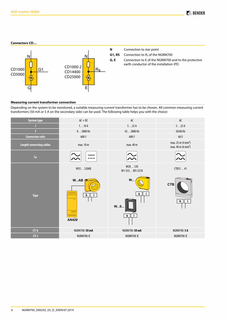
Measuring current transformer connectionDepending on the system to be monitored, a suitable measuring current transformer has to be chosen. All common measuring current transformers (50 mA or 5 A on the secondary side) can be used. The following table helps you with the choice:
System type AC + DC AC AC
I 1…10 A 5…25 A 5…25 A
f 0…3800 Hz 42…3800 Hz 50/60 Hz
Conversion ratio 600:1 600:1 60:5
Length connecting cables max. 10 m max. 40 mmax. 25 m (4 mm²) max. 40 m (6 mm²)
IΔn
Type
W35…120ABW20…120
W1-S35…W5-S210CTB31…41
k l
W...AB
AN420
W...
W...S...
k l
k l
k l
CTB
CT: k NGRM700: 50 mA NGRM700: 50 mA NGRM700: 5 A
CT: l NGRM700: C NGRM700: C NGRM700: C
Connectors CD…
Rs
E
N
CD1000-2CD14400CD25000
G1
G
N
CD1000CD5000
N Connection to star point
G1, RS Connection to RS of the NGRM700
G, E Connection to E of the NGRM700 and to the protective earth conductor of the installation (PE)
NGRM700_D00292_03_D_XXEN/07.2019 7
NGR monitor NGRM
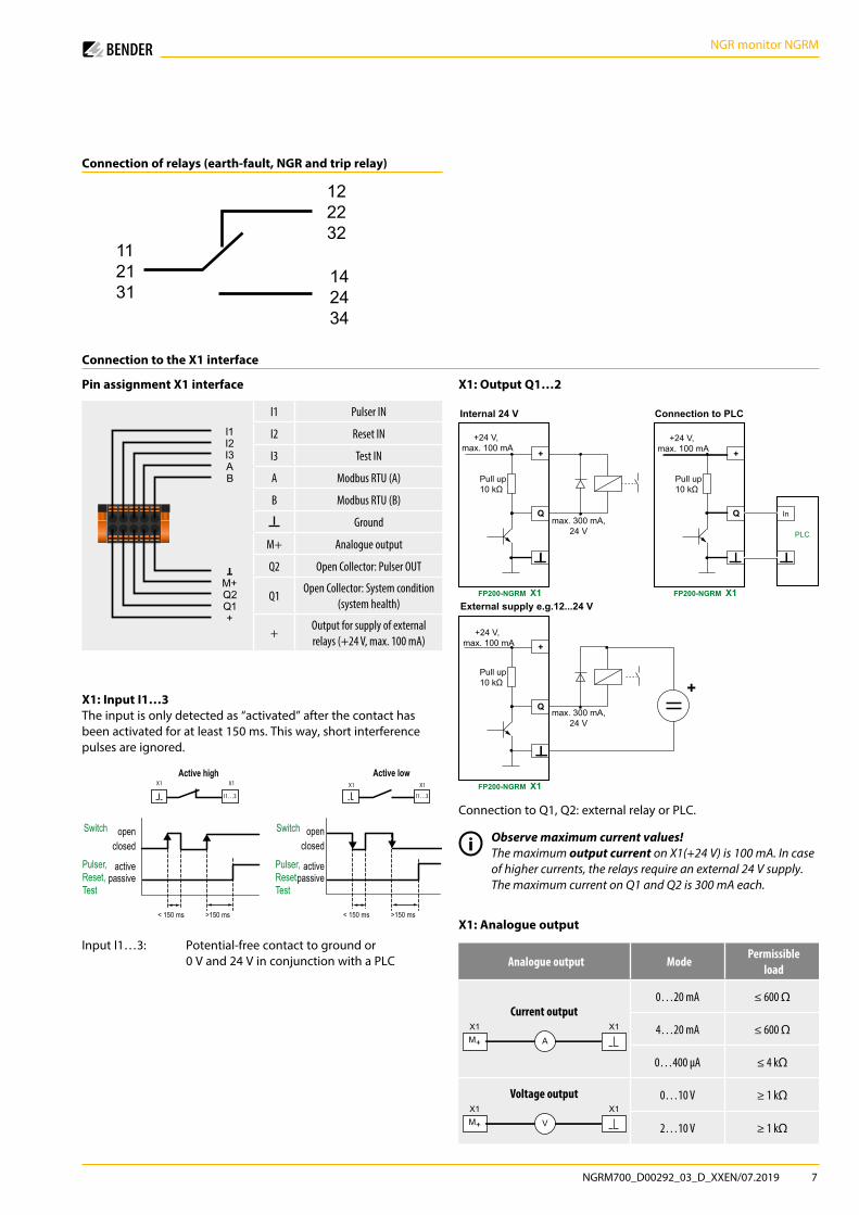
Connection to the X1 interface
X1: Input I1…3The input is only detected as “activated” after the contact has been activated for at least 150 ms. This way, short interference pulses are ignored.
X1: Output Q1…2
X1: Analogue output
Connection of relays (earth-fault, NGR and trip relay)
I1 I2I3AB
M+Q2Q1+
I1 Pulser IN
I2 Reset IN
I3 Test IN
A Modbus RTU (A)
B Modbus RTU (B)
Ground
M+ Analogue output
Q2 Open Collector: Pulser OUT
Q1Open Collector: System condition
(system health)
+Output for supply of externalrelays (+24 V, max. 100 mA)
112131
122232
142434
Pull up10 kΩ
FP200-NGRM X1
+24 V, max. 100 mA +
Qmax. 300 mA,
24 V
Pull up10 kΩ
FP200-NGRM X1
+24 V, max. 100 mA +
Qmax. 300 mA,
24 V
+
Pull up10 kΩ
FP200-NGRM X1
+24 V, max. 100 mA +
Q In
Internal 24 V
External supply e.g.12...24 V
Connection to PLC
PLC
Connection to Q1, Q2: external relay or PLC.
< 150 ms >150 ms
I1…3
X1 X1
I1…3
X1 X1
< 150 ms >150 ms
openSwitchclosed
activepassive
openclosed
activepassive
Switch
Active lowActive high
Pulser, Reset,Test
Pulser, Reset,Test
Analogue output ModePermissible
load
Current output
M+ A
X1 X1
0…20 mA ≤ 600 Ω
4…20 mA ≤ 600 Ω
0…400 μA ≤ 4 kΩ
Voltage output
M+ V
X1 X10…10 V ≥ 1 kΩ
2…10 V ≥ 1 kΩ
Pin assignment X1 interface
Input I1…3: Potential-free contact to ground or 0 V and 24 V in conjunction with a PLC
i Observe maximum current values!
The maximum output current on X1(+24 V) is 100 mA. In case of higher currents, the relays require an external 24 V supply. The maximum current on Q1 and Q2 is 300 mA each.
8 NGRM700_D00292_03_D_XXEN/07.2019
NGR monitor NGRM
Technical Data
Insulation coordination according to IEC 60664-1/IEC 60664-3/DIN EN 50187Definitions Measuring circuit 1 (IC1) (L1, L2, L3)
Supply circuit (IC2) (A1, A2) Measuring circuit/Control circuit (IC3) (RS, E, CT), (X1, Ethernet) Output circuit 1 (IC4) (11, 12, 14) Output circuit 2 (IC5) (21, 22, 24) Output circuit 3 (IC6) (31, 32, 34)
Rated voltage 690 VOvervoltage category IIIRated impulse voltage IC1/(IC2…6) 8 kV
IC2/(IC3…6) 4 kV IC3/(IC4…6) 4 kV IC4/(IC5…6) 4 kV IC5/(IC6) 4 kV
Rated insulation voltage IC1/(IC2…6) 800 V
IC2/(IC3…6) 250 V IC3/(IC4…6) 250 V IC4/(IC5…6) 250 V IC5/(IC6) 250 V
Pollution degree exterior 3Safe isolation (reinforced insulation) between IC1/(IC2…6) overvoltage category III, 800 V
IC2/(IC3…6) overvoltage category III, 300 V IC3/(IC4…6) overvoltage category III, 300 V IC4/(IC5…6) overvoltage category III, 300 V IC5/(IC6) overvoltage category III, 300 V
Voltage tests (routine test) acc. to IEC 61010-1 IC2/(IC3…6) AC 2.2 kV
IC3/(IC4…6) AC 2.2 kV IC4/(IC5…6) AC 2.2 kV IC5/(IC6) AC 2.2 kV
Supply voltageNominal supply voltage Us ≤ 2000 m AC/DC, 24…240 V
≤ 2000 m (for UL applications) AC/DC, 48…240 V ≤ 2000 m (for AS/NZS 2081) AC/DC, 48…230 V > 2000…≤ 5000 m AC/DC, 24…120 V > 2000…≤ 5000 m (for UL applications, AS/NZS 2081) AC/DC, 48…120 V
Tolerance Us ±15 %Tolerance Us (for UL applications) -50…+15 %Tolerance Us (for AS/NZS 2081) -25…+20 %Frequency range – DC, 40…70 HzPower consumption (typ. 50/60 Hz) ≤ 6.5 W/13 VA
Phase monitoringNominal measuring voltage Un 3 AC 100…690 V, CAT IIIMeasuring range 1.2 x Un
Measurement accuracy ±1 % of Un
Power consumption per phase ≤ 0.5 WOverload capacity 2 x Un continuousInput resistance 1,76 MΩPT ratio primary 1…10,000PT ratio secondary 1…10,000Measuring range with PT 100 V…25 kV
Monitoring RNGR
Measuring input RS < 33 V RMSMeasuring range NGR (with RS = 20 kΩ) active 0…10 kΩ Measurement uncertainty for T = 0…+40 °C ±20 Ω Measurement uncertainty for T = -40…+70 °C ±40 ΩMeasuring range NGR (with RS = 100 kΩ) active 0…10 kΩ Measurement uncertainty for T = 0…+40 °C ±30 Ω Measurement uncertainty for T = -40…+70 °C ±80 ΩSetting range RNGR nom 15 Ω…5 kΩResponse value RNGR nom 10…90 % RNGR nom 110…200 % RNGR nom
Response delay NGR relay 7 s (±2.5 s)Response delay trip relay 0…60 s
Monitoring INGR
Measuring circuit 5 A Nominal measuring current In DC/50/60 Hz/50…3200 Hz 5 A
Maximum continuous current 2 x In Overload capacity 10 x In for 2 s Measurement accuracy ±2 % of In Load 10 mΩ
Measuring circuit 50 mA Nominal measuring current In DC/50/60 Hz/50…3200 Hz 50 mA
Maximum continuous current 2 x In Overload capacity 10 x In for 2 s Measurement accuracy ±2 % of In Load 68 Ω
Measuring circuits 5 A and 50 mA Response value INGR 10…90 % INGR nom
Response delay ground-fault relay ≤ 40 ms (±10 ms) Response delay trip relay (configurable) 100 ms…24 h, ∞
Tolerance ttrip when set to RMS -20…0 ms
Fundamental 0…+150 ms (filter time) Harmonics 0…+150 ms (filter time)
Measuring current transformer ratio primary 1…10,000Measuring current transformer ratio secondary 1…10,000Measuring range 2 x INGR nom
CouplingRS for Usys ≤ 4.3 kV CD1000, CD1000-2, CD5000 (20 kΩ)RS for Usys > 4.3 kV CD14400, CD25000 (100 kΩ)
Monitoring UNGR
UNGR with RS = 20 kΩ DC/50/60 Hz/50…3200 Hz; (400/√3) … ≤ (4300/√3) VUNGR with RS = 100 kΩ DC/50/60 Hz/50…3200 Hz; > (4.3 /√3) …(25/√3) kVMeasuring range 1.2 x UNGR nom
Overload capacity 2 x UNGR for 10 sMeasurement accuracy 2 % of UNGR nom with UNGR nom = (Usys (L-L)/√3)Voltage response value 0…100 % UNGR nom
Response delay ground-fault relay ≤ 40 ms (±10 ms)Response delay trip relay (configurable) 100 ms…24 h, ∞Tolerance ttrip when set to RMS -20…0 ms
Fundamental 0…+150 ms (filter time) Harmonics 0…+150 ms (filter time)
PT ratio primary 1…10,000PT ratio secondary 1…10,000DC immunity in case of active RNGR measurement with RS = 20 kΩ DC ±12 V
with RS = 100 kΩ DC ±60 V
NGRM700_D00292_03_D_XXEN/07.2019 9
NGR monitor NGRM
Digital inputsGalvanic separation noLength connecting cables max. 10 mUin DC 0 V, 24 VOverload capacity -5…32 V
Digital outputsGalvanic separation noLength connecting cables max. 10 mCurrents (sink) for each output max. 300 mAVoltage 24 VOverload capacity -5…32 V
Analogue output (M+)Operating mode LinearFunctions INGR, RNGR
Current 0…20 mA (≤ 600 Ω), 4…20 mA (≤ 600 Ω), 0…400 μA (≤ 4 kΩ)Voltage 0…10 V (≥ 1 kΩ), 2…10 V (≥ 1 kΩ)Tolerance related to the current/voltage end value ±20 %
Ground-fault, NGR, trip relaySwitching elements changeover contactsOperating mode configurable fail-safe/non-fail-safeElectrical endurance, number of cycles 10,000Switching capacity 2000 VA/150 W
Contact data acc. to IEC 60947-5-1Rated operational voltage AC 250 V/250 VUtilisation category AC-13/AC-14Rated operational current AC 5 A/3 ARated operational current AC (for UL applications) 3 A/3 ARated operational voltage DC 220/110/24 VUtilisation category DC12Rated operational current DC 0.1/0.2/1 AMinimum current 1 mA at AC/DC > 10 V
Environment/EMCEMC immunity (IEC 6100-6-2/IEC 60255-26 Ed. 3.0) DIN EN 61000-6-2EMC emission (IEC 6100-6-2/IEC 60255-26 Ed. 3.0) DIN EN 61000-6-4Operating temperature -40…+70 °C -40…+60 °C (for UL applications)Humidity ≤ 98 %
Classification of climatic conditions acc. to IEC 60721Stationary use (IEC 60721-3-3) 3K5 (except condensation and formation of ice)Transport (IEC 60721-3-2) 2K3 (-40…+85 °C) (except condensation and formation of ice)Long-term storage (IEC 60721-3-1) 1K4 (-40…+70 °C) (except condensation and formation of ice)
Classification of mechanical conditions acc. to IEC 60721/IEC 60255-21/DIN EN 60068-2-6Stationary use 3M7Transport 2M2Long-term storage 1M3
Connection
Screw-type terminalsTightening torque 0.5…0.6 Nm (5…7 lb-in)Conductor sizes AWG 24-12Stripping length 7 mmrigid/flexible 0.2…2.5 mm²flexible with ferrule with/without plastic sleeve 0.25…2.5 mm²Multiple conductor, rigid 0.2…1 mm²Multiple conductor flexible 0.2…1.5 mm²Multiple conductor flexible with ferrule without plastic sleeve 0.25…1 mm²Multiple conductor, flexible with TWIN ferrule with plastic sleeve 0.5…1.5 mm²
Push-wire terminals X1Conductor sizes AWG 24-16Stripping length 10 mmrigid/flexible 0.2…1.5 mm²flexible with ferrule without plastic sleeve 0.25…1.5 mm²flexible with ferrule with plastic sleeve 0.25…0.75 mm²
OtherOperating mode continuous operationMounting display-orientedAltitude 5000 m AMSLDegree of protection, internal components (DIN EN 60529) IP30Flammability class UL 94V-0Protective coating measurement equipment SL1307, UL file E80315Documentation number D00292Weight 1050 g
10 NGRM700_D00292_03_D_XXEN/07.2019
NGR monitor NGRM
Supply voltage US / Frequency range Hz Type Art. No.
AC DC24…240 V, 40…70 Hz 24…240 V NGRM700 B94013700
Ordering information
Description Art. No.
Accessory for FP200-NGRM:Transparent front cover 144x72 (for IP65)1) B98060005
1) When using the "transparent front cover 144x72 (IP 65)" the cutout in the switchboard cabinet must be extended in height from 66 mm to 68 mm (+0.7/-0 mm).
The degree of protection IP65 applies only to the user interface FP200-NGRM when using the front cover. The degree of protection for the complete device is still IP30.
Accessories
Suitable system components
DescriptionSupply voltage
TypeArt. No.
AC DCScrew-type
terminalPush-wire terminal
Voltage supply for measuring
current transformers
100…250 V, 50/60 Hz
100…250 V AN420 B94053100 B74053100
Description Voltage Usys Type Art. No.
CD-series coupling device
400…690 V CD1000 B98039010
400…1000 V CD1000-2 B98039053
1000…4200 V CD5000 B98039011
4300…14550 V CD14400 On request
14551…25000 V CD25000 On request
Description Voltage/Current Type Art. No.
Measuring current transformer
AC up to 10 A W20 B98080003
AC up to 25 A
W35 B98080010
W60 B98080018
W0-S20 B911787
W1-S35 B911731
W2-S70 B911732
AC/DC up to 10 AW35AB B98080016
W60AB B98080026
W120AB B98039011
NGRM700_D00292_03_D_XXEN/07.2019 11
NGR monitor NGRM
a
kji
hgf
e
d
cb
l
af
e
dc
b
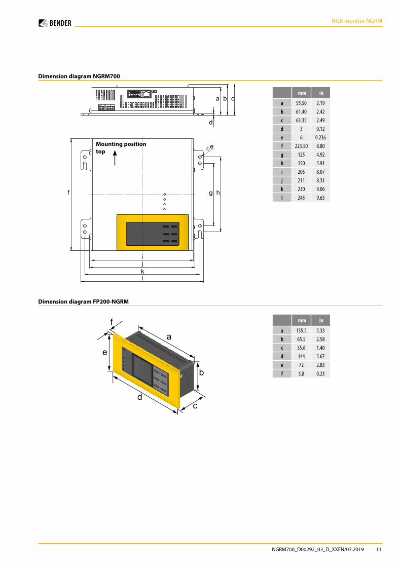
Dimension diagram NGRM700
Dimension diagram FP200-NGRM
mm in
a 55.50 2.19b 61.40 2.42c 63.35 2.49d 3 0.12e 6 0.236f 223.50 8.80g 125 4.92h 150 5.91i 205 8.07j 211 8.31k 230 9.06l 245 9.65
mm in
a 135.5 5.33b 65.5 2.58c 35.6 1.40d 144 5.67e 72 2.83f 5.8 0.23
Mounting position top

Bender GmbH & Co. KGPostfach 1161 • 35301 Grünberg • GermanyLondorfer Straße 65 • 35305 Grünberg • GermanyTel.: +49 6401 807-0 • Fax: +49 6401 807-259E-Mail: [email protected] • www.bender.de
NG
RM70
0_D
0029
2_03
_D_X
XEN
/ 07
.201
9 / p
df /
© B
ende
r Gm
bH &
Co.
KG
, Ger
man
y –
Subj
ect t
o ch
ange
! The
spe
cifie
d st
anda
rds
take
into
acc
ount
the
editi
on v
alid
unt
il 07
.201
9 un
less
oth
erw
ise
indi
cate
d.
BENDER Group