Embed Size (px)
Citation preview
NetworXTM NX-8E Alarm PanelN
etworX
NX
-8EA
pplication Note
The PXL-510 tiger controller can be connected with the NetworX1 NX-8E Alarm panel to allow arming and disarming of the alarm system by using the alarm panel keypad, using a wireless Wiegand device, or simply presenting an access card. This document covers the necessary information for configuring the NX-8E Alarm panel so that communication between the alarm panel and the PXL-510 may occur. For instructions on installing the PXL-510 Tiger Controller refer to the PXL-500/PXL-510 Quick Start Guide (P/N 01918-001). For detailed instructions on installing the NetworX NX-8E Alarm Panel refer to the instructions provided by NetworX.
1.0 The NetworX NX-8E Alarm PanelIn order for communication to take place between the PXL-510 master controller and the NetworX NX-8E Alarm Control Panel, the alarm control panel must be configured to use the NetworX NX584 protocol. The following steps will take you through that process. For detailed information concerning the function of the alarm panel, see the NX-8E Installation Manual.
Figure 1: NetworX NX-8E Alarm Panel
1. NetworX is a trademark of GE Interlogix.
1530 Old Oakland Road, Suite 100 01919-001 Rev. 2.0San Jose, CA 95112 USA(800) 260-5265 (408) 451-2520 FAX (408) 441-0309Web: http://www.kerisys.com E-mail: [email protected] Page 1 of 14
NetworXTM NX-8E Alarm PanelA
pplic
atio
n N
ote
Net
wor
X N
X-8
E
2.0 Configure the NX-8E Alarm Panel1. When the alarm control panel is first powered up, the LCD shows the following message (see Figure 2).Figure 2: Alarm Panel - System Ready
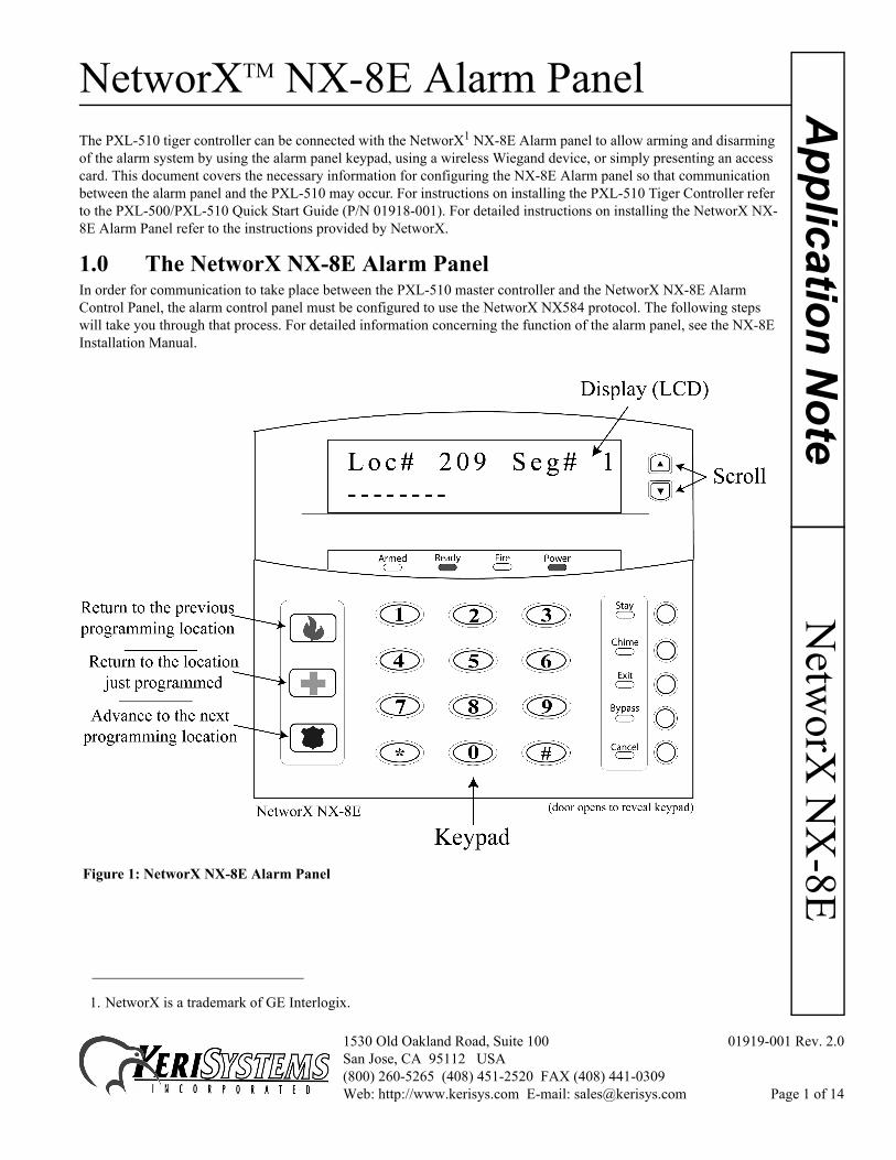
2. To enter the alarm panel programming mode, select the keys. The alarm panel keypad will beep three times then prompt for the programming code (see Figure 3).
Figure 3: Alarm Panel - Enter Code
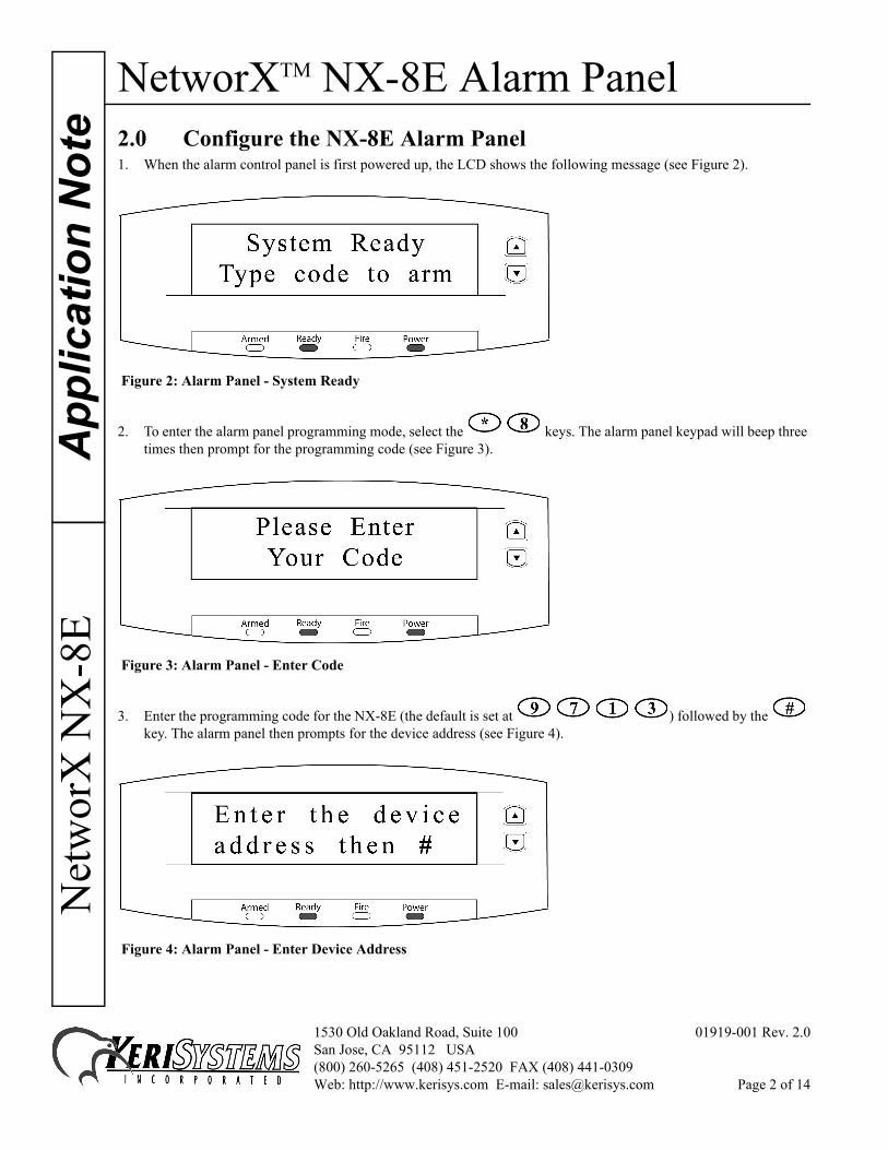
3. Enter the programming code for the NX-8E (the default is set at ) followed by the key. The alarm panel then prompts for the device address (see Figure 4).
Figure 4: Alarm Panel - Enter Device Address
1530 Old Oakland Road, Suite 100 01919-001 Rev. 2.0San Jose, CA 95112 USA(800) 260-5265 (408) 451-2520 FAX (408) 441-0309Web: http://www.kerisys.com E-mail: [email protected] Page 2 of 14
NetworXTM NX-8E Alarm PanelN
etworX
NX
-8EA
pplication Note
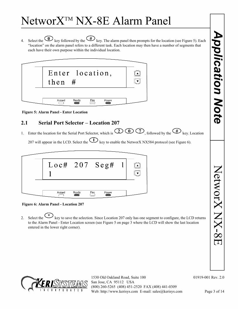
4. Select the key followed by the key. The alarm panel then prompts for the location (see Figure 5). Each “location” on the alarm panel refers to a different task. Each location may then have a number of segments that each have their own purpose within the individual location.
Figure 5: Alarm Panel - Enter Location
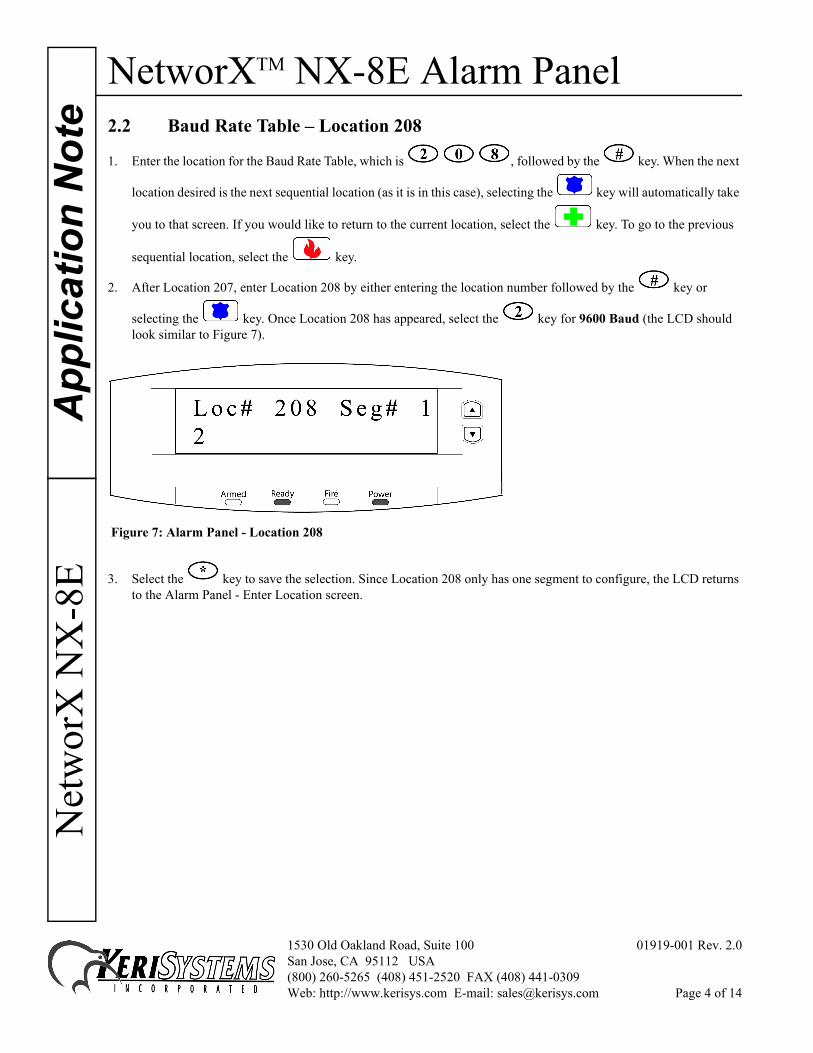
2.1 Serial Port Selector – Location 207
1. Enter the location for the Serial Port Selector, which is , followed by the key. Location
207 will appear in the LCD. Select the key to enable the NetworX NX584 protocol (see Figure 6).
Figure 6: Alarm Panel - Location 207
2. Select the key to save the selection. Since Location 207 only has one segment to configure, the LCD returns to the Alarm Panel - Enter Location screen (see Figure 5 on page 3 where the LCD will show the last location entered in the lower right corner).
1530 Old Oakland Road, Suite 100 01919-001 Rev. 2.0San Jose, CA 95112 USA(800) 260-5265 (408) 451-2520 FAX (408) 441-0309Web: http://www.kerisys.com E-mail: [email protected] Page 3 of 14
NetworXTM NX-8E Alarm PanelA
pplic
atio
n N
ote
Net
wor
X N
X-8
E
2.2 Baud Rate Table – Location 2081. Enter the location for the Baud Rate Table, which is , followed by the key. When the next
location desired is the next sequential location (as it is in this case), selecting the key will automatically take
you to that screen. If you would like to return to the current location, select the key. To go to the previous
sequential location, select the key.
2. After Location 207, enter Location 208 by either entering the location number followed by the key or
selecting the key. Once Location 208 has appeared, select the key for 9600 Baud (the LCD should look similar to Figure 7).
Figure 7: Alarm Panel - Location 208
3. Select the key to save the selection. Since Location 208 only has one segment to configure, the LCD returns to the Alarm Panel - Enter Location screen.
1530 Old Oakland Road, Suite 100 01919-001 Rev. 2.0San Jose, CA 95112 USA(800) 260-5265 (408) 451-2520 FAX (408) 441-0309Web: http://www.kerisys.com E-mail: [email protected] Page 4 of 14
NetworXTM NX-8E Alarm PanelN
etworX
NX
-8EA
pplication Note
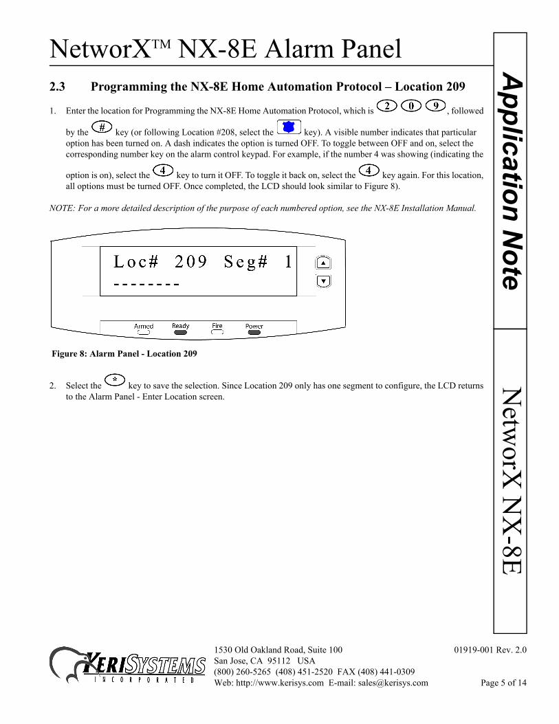
2.3 Programming the NX-8E Home Automation Protocol – Location 209
1. Enter the location for Programming the NX-8E Home Automation Protocol, which is , followed
by the key (or following Location #208, select the key). A visible number indicates that particular option has been turned on. A dash indicates the option is turned OFF. To toggle between OFF and on, select the corresponding number key on the alarm control keypad. For example, if the number 4 was showing (indicating the
option is on), select the key to turn it OFF. To toggle it back on, select the key again. For this location, all options must be turned OFF. Once completed, the LCD should look similar to Figure 8).
NOTE: For a more detailed description of the purpose of each numbered option, see the NX-8E Installation Manual.
Figure 8: Alarm Panel - Location 209
2. Select the key to save the selection. Since Location 209 only has one segment to configure, the LCD returns to the Alarm Panel - Enter Location screen.
1530 Old Oakland Road, Suite 100 01919-001 Rev. 2.0San Jose, CA 95112 USA(800) 260-5265 (408) 451-2520 FAX (408) 441-0309Web: http://www.kerisys.com E-mail: [email protected] Page 5 of 14
NetworXTM NX-8E Alarm PanelA
pplic
atio
n N
ote
Net
wor
X N
X-8
E
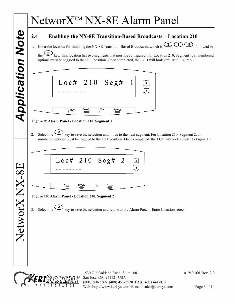
2.4 Enabling the NX-8E Transition-Based Broadcasts – Location 2101. Enter the location for Enabling the NX-8E Transition-Based Broadcasts, which is , followed by
the key. This location has two segments that must be configured. For Location 210, Segment 1, all numbered options must be toggled to the OFF position. Once completed, the LCD will look similar to Figure 9.
Figure 9: Alarm Panel - Location 210, Segment 1
2. Select the key to save the selection and move to the next segment. For Location 210, Segment 2, all numbered options must be toggled to the OFF position. Once completed, the LCD will look similar to Figure 10.
Figure 10: Alarm Panel - Location 210, Segment 2
3. Select the key to save the selection and return to the Alarm Panel - Enter Location screen.
1530 Old Oakland Road, Suite 100 01919-001 Rev. 2.0San Jose, CA 95112 USA(800) 260-5265 (408) 451-2520 FAX (408) 441-0309Web: http://www.kerisys.com E-mail: [email protected] Page 6 of 14
NetworXTM NX-8E Alarm PanelN
etworX
NX
-8EA
pplication Note
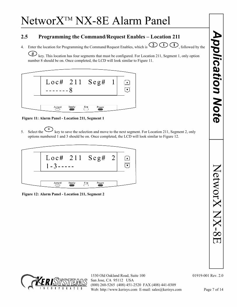
2.5 Programming the Command/Request Enables – Location 211
4. Enter the location for Programming the Command/Request Enables, which is , followed by the
key. This location has four segments that must be configured. For Location 211, Segment 1, only option number 8 should be on. Once completed, the LCD will look similar to Figure 11.
Figure 11: Alarm Panel - Location 211, Segment 1
5. Select the key to save the selection and move to the next segment. For Location 211, Segment 2, only options numbered 1 and 3 should be on. Once completed, the LCD will look similar to Figure 12.
Figure 12: Alarm Panel - Location 211, Segment 2
1530 Old Oakland Road, Suite 100 01919-001 Rev. 2.0San Jose, CA 95112 USA(800) 260-5265 (408) 451-2520 FAX (408) 441-0309Web: http://www.kerisys.com E-mail: [email protected] Page 7 of 14
NetworXTM NX-8E Alarm PanelA
pplic
atio
n N
ote
Net
wor
X N
X-8
E
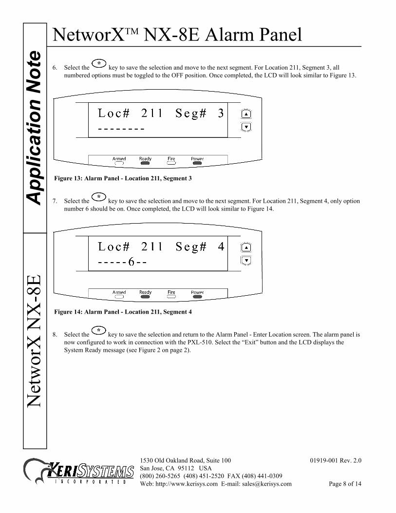
6. Select the key to save the selection and move to the next segment. For Location 211, Segment 3, allnumbered options must be toggled to the OFF position. Once completed, the LCD will look similar to Figure 13.
Figure 13: Alarm Panel - Location 211, Segment 3
7. Select the key to save the selection and move to the next segment. For Location 211, Segment 4, only option number 6 should be on. Once completed, the LCD will look similar to Figure 14.
Figure 14: Alarm Panel - Location 211, Segment 4
8. Select the key to save the selection and return to the Alarm Panel - Enter Location screen. The alarm panel is now configured to work in connection with the PXL-510. Select the “Exit” button and the LCD displays the System Ready message (see Figure 2 on page 2).
1530 Old Oakland Road, Suite 100 01919-001 Rev. 2.0San Jose, CA 95112 USA(800) 260-5265 (408) 451-2520 FAX (408) 441-0309Web: http://www.kerisys.com E-mail: [email protected] Page 8 of 14
NetworXTM NX-8E Alarm PanelN
etworX
NX
-8EA
pplication Note
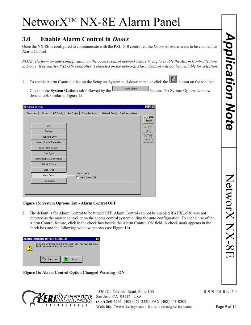
3.0 Enable Alarm Control in DoorsOnce the NX-8E is configured to communicate with the PXL-510 controller, the Doors software needs to be enabled for Alarm Control.
NOTE: Perform an auto configuration on the access control network before trying to enable the Alarm Control feature in Doors. If no master PXL-510 controller is detected on the network, Alarm Control will not be available for selection.
1. To enable Alarm Control, click on the Setup ⇒ System pull-down menu or click the button on the tool bar.
Click on the System Options tab followed by the button. The System Options window should look similar to Figure 15.
Figure 15: System Options Tab - Alarm Control OFF
2. The default is for Alarm Control to be turned OFF. Alarm Control can not be enabled if a PXL-510 was not detected as the master controller on the access control system during the auto configuration. To enable use of the Alarm Control feature, click in the check box beside the Alarm Control ON field. A check mark appears in the check box and the following window appears (see Figure 16).
Figure 16: Alarm Control Option Changed Warning - ON
1530 Old Oakland Road, Suite 100 01919-001 Rev. 2.0San Jose, CA 95112 USA(800) 260-5265 (408) 451-2520 FAX (408) 441-0309Web: http://www.kerisys.com E-mail: [email protected] Page 9 of 14
NetworXTM NX-8E Alarm PanelA
pplic
atio
n N
ote
Net
wor
X N
X-8
E
3. To enable Alarm Control, click on the button. A “Saved Configuration” window flashes on the screen.4. Now click on the button on the tool bar and update the access control network with the new information. For details on the update process refer to the Doors Users Guide (P/N 01914-100).
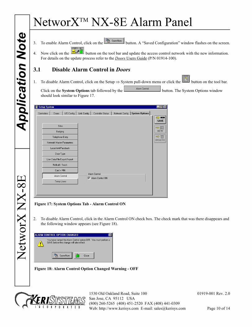
3.1 Disable Alarm Control in Doors
1. To disable Alarm Control, click on the Setup ⇒ System pull-down menu or click the button on the tool bar.
Click on the System Options tab followed by the button. The System Options window should look similar to Figure 17.
Figure 17: System Options Tab - Alarm Control ON
2. To disable Alarm Control, click in the Alarm Control ON check box. The check mark that was there disappears and the following window appears (see Figure 18).
Figure 18: Alarm Control Option Changed Warning - OFF
1530 Old Oakland Road, Suite 100 01919-001 Rev. 2.0San Jose, CA 95112 USA(800) 260-5265 (408) 451-2520 FAX (408) 441-0309Web: http://www.kerisys.com E-mail: [email protected] Page 10 of 14
NetworXTM NX-8E Alarm PanelN
etworX
NX
-8EA
pplication Note
3. Click the button. A “Saved Configuration” window flashes on the screen.
4. Now click on the button on the tool bar and update the access control network with the new information. For details on the update process refer to the Doors Users Guide (P/N 01914-100).
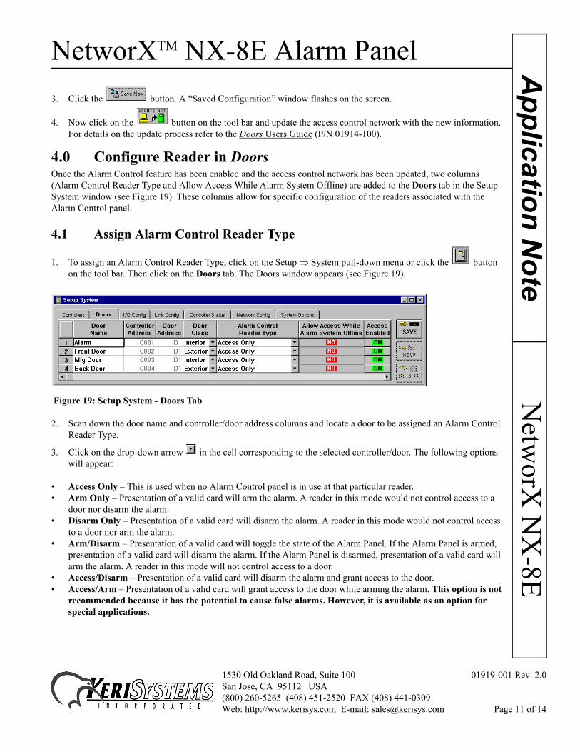
4.0 Configure Reader in DoorsOnce the Alarm Control feature has been enabled and the access control network has been updated, two columns (Alarm Control Reader Type and Allow Access While Alarm System Offline) are added to the Doors tab in the Setup System window (see Figure 19). These columns allow for specific configuration of the readers associated with the Alarm Control panel.
4.1 Assign Alarm Control Reader Type
1. To assign an Alarm Control Reader Type, click on the Setup ⇒ System pull-down menu or click the button on the tool bar. Then click on the Doors tab. The Doors window appears (see Figure 19).
Figure 19: Setup System - Doors Tab
2. Scan down the door name and controller/door address columns and locate a door to be assigned an Alarm Control Reader Type.
3. Click on the drop-down arrow in the cell corresponding to the selected controller/door. The following options will appear:
• Access Only – This is used when no Alarm Control panel is in use at that particular reader.• Arm Only – Presentation of a valid card will arm the alarm. A reader in this mode would not control access to a
door nor disarm the alarm.• Disarm Only – Presentation of a valid card will disarm the alarm. A reader in this mode would not control access
to a door nor arm the alarm.• Arm/Disarm – Presentation of a valid card will toggle the state of the Alarm Panel. If the Alarm Panel is armed,
presentation of a valid card will disarm the alarm. If the Alarm Panel is disarmed, presentation of a valid card will arm the alarm. A reader in this mode will not control access to a door.
• Access/Disarm – Presentation of a valid card will disarm the alarm and grant access to the door.• Access/Arm – Presentation of a valid card will grant access to the door while arming the alarm. This option is not
recommended because it has the potential to cause false alarms. However, it is available as an option for special applications.
1530 Old Oakland Road, Suite 100 01919-001 Rev. 2.0San Jose, CA 95112 USA(800) 260-5265 (408) 451-2520 FAX (408) 441-0309Web: http://www.kerisys.com E-mail: [email protected] Page 11 of 14
NetworXTM NX-8E Alarm PanelA
pplic
atio
n N
ote
Net
wor
X N
X-8
E
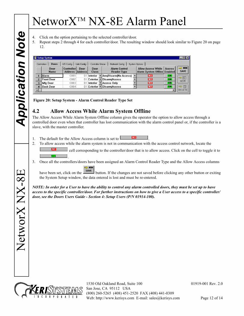
4. Click on the option pertaining to the selected controller/door.5. Repeat steps 2 through 4 for each controller/door. The resulting window should look similar to Figure 20 on page12.
Figure 20: Setup System - Alarm Control Reader Type Set
4.2 Allow Access While Alarm System OfflineThe Allow Access While Alarm System Offline column gives the operator the option to allow access through a controlled door even when that controller has lost communication with the alarm control panel or, if the controller is a slave, with the master controller.
1. The default for the Allow Access column is set to .2. To allow access while the alarm system is not in communication with the access control network, locate the
cell corresponding to the controller/door that is to allow access. Click on the cell to toggle it to
. 3. Once all the controllers/doors have been assigned an Alarm Control Reader Type and the Allow Access columns
have been set, click on the button. If the changes are not saved before clicking any other button or exiting the System Setup window, the data entered is lost and must be re-entered.
NOTE: In order for a User to have the ability to control any alarm controlled doors, they must be set up to have access to the specific controller/door. For further instructions on how to give a User access to a specific controller/door, see the Doors Users Guide - Section 4: Setup Users (P/N 01914-100).
1530 Old Oakland Road, Suite 100 01919-001 Rev. 2.0San Jose, CA 95112 USA(800) 260-5265 (408) 451-2520 FAX (408) 441-0309Web: http://www.kerisys.com E-mail: [email protected] Page 12 of 14
NetworXTM NX-8E Alarm PanelN
etworX
NX
-8EA
pplication Note
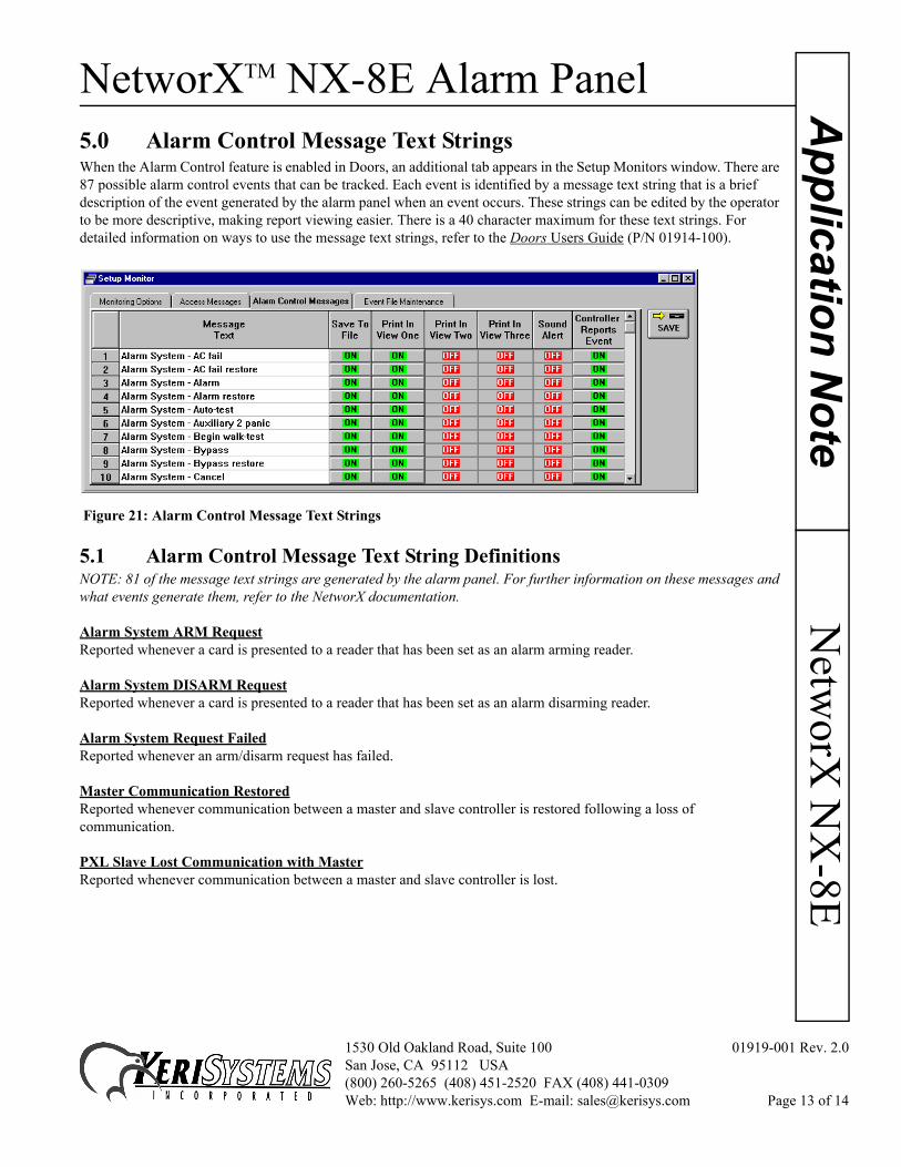
5.0 Alarm Control Message Text StringsWhen the Alarm Control feature is enabled in Doors, an additional tab appears in the Setup Monitors window. There are 87 possible alarm control events that can be tracked. Each event is identified by a message text string that is a brief description of the event generated by the alarm panel when an event occurs. These strings can be edited by the operator to be more descriptive, making report viewing easier. There is a 40 character maximum for these text strings. For detailed information on ways to use the message text strings, refer to the Doors Users Guide (P/N 01914-100).
Figure 21: Alarm Control Message Text Strings
5.1 Alarm Control Message Text String DefinitionsNOTE: 81 of the message text strings are generated by the alarm panel. For further information on these messages and what events generate them, refer to the NetworX documentation.
Alarm System ARM RequestReported whenever a card is presented to a reader that has been set as an alarm arming reader.
Alarm System DISARM RequestReported whenever a card is presented to a reader that has been set as an alarm disarming reader.
Alarm System Request FailedReported whenever an arm/disarm request has failed.
Master Communication RestoredReported whenever communication between a master and slave controller is restored following a loss of communication.
PXL Slave Lost Communication with MasterReported whenever communication between a master and slave controller is lost.
1530 Old Oakland Road, Suite 100 01919-001 Rev. 2.0San Jose, CA 95112 USA(800) 260-5265 (408) 451-2520 FAX (408) 441-0309Web: http://www.kerisys.com E-mail: [email protected] Page 13 of 14
NetworXTM NX-8E Alarm PanelA
pplic
atio
n N
ote
Net
wor
X N
X-8
E
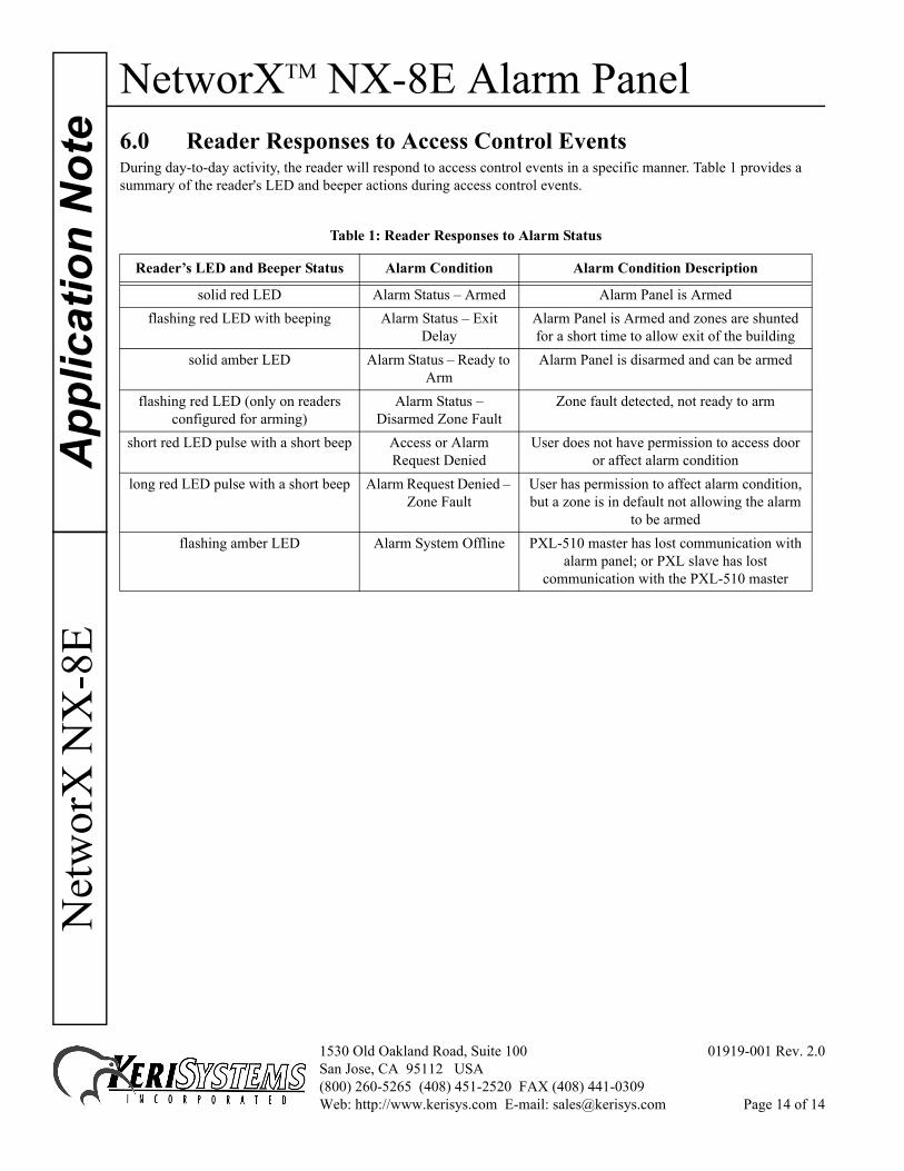
6.0 Reader Responses to Access Control EventsDuring day-to-day activity, the reader will respond to access control events in a specific manner. Table 1 provides a summary of the reader's LED and beeper actions during access control events.Table 1: Reader Responses to Alarm Status
Reader’s LED and Beeper Status Alarm Condition Alarm Condition Description
solid red LED Alarm Status – Armed Alarm Panel is Armedflashing red LED with beeping Alarm Status – Exit
Delay Alarm Panel is Armed and zones are shunted for a short time to allow exit of the building
solid amber LED Alarm Status – Ready to Arm
Alarm Panel is disarmed and can be armed
flashing red LED (only on readers configured for arming)
Alarm Status – Disarmed Zone Fault
Zone fault detected, not ready to arm
short red LED pulse with a short beep Access or Alarm Request Denied
User does not have permission to access door or affect alarm condition
long red LED pulse with a short beep Alarm Request Denied – Zone Fault
User has permission to affect alarm condition, but a zone is in default not allowing the alarm
to be armedflashing amber LED Alarm System Offline PXL-510 master has lost communication with
alarm panel; or PXL slave has lost communication with the PXL-510 master
1530 Old Oakland Road, Suite 100 01919-001 Rev. 2.0San Jose, CA 95112 USA(800) 260-5265 (408) 451-2520 FAX (408) 441-0309Web: http://www.kerisys.com E-mail: [email protected] Page 14 of 14