Embed Size (px)
Citation preview

Networks 2005 A Brave New Networked World of Broadcasting organized with the EBU Network Technology Management Committee (NMC) EBU Headquarters, Geneva 21 and 22 June 2005
Report by Rhys Lewis, Head of Technology Strategy, Technology Direction, BBC, United
Kingdom & Jean-Nöel Gouyet, Trainer, technical writer, France
EBU/UER EBU International Training L'Ancienne-Route 17A CH-1218 Grand-Saconnex GE Switzerland / Suisse
Tel.: +41 (0) 22 717 21 46 Fax: +41 (0) 22 747 41 46 e-mail: [email protected] http://www.ebu.ch/training

1
Networks 2005 report
Introduction ............................................................................................................... 2
1 Real-time networks .......................................................................................... 2 1.1 IP-based networks ..........................................................................................................2 1.1.1 IP ‘light’ refresher ...................................................................................................................... 2 1.1.2 SVT Contribution Network......................................................................................................... 3 1.1.3 BBC’s plans for one ‘good network’ .......................................................................................... 4 1.2 Non-IP networks .............................................................................................................5 1.2.1 Techno primer (NG-SDH, DTM)................................................................................................ 5 1.2.2 EBU Contribution networks ....................................................................................................... 6 1.2.3 Evolution of RAI Contribution & Distribution network towards NG-SDH................................... 6 1.2.4 WDR RegioNet network ............................................................................................................ 7 1.3 To be IP or not to be? .....................................................................................................8 1.4 Services ..........................................................................................................................9 1.4.1 MusiPOP (Point of Presence): Downloading concerts over networks ...................................... 9 1.4.2 HDTV - Distribution & Broadcasting........................................................................................ 10 2 Controlling & Monitoring............................................................................... 10 2.1 For an integrated approach ..........................................................................................10 2.2 SNMP Primer................................................................................................................12 2.3 Common Control Standard for network connected equipment .....................................12 2.4 VRT - Monitoring & controlling Broadcast equipment ...................................................13 2.5 TDF - End-to-end QoS monitoring...............................................................................14
3 Security........................................................................................................... 14 3.1 Network Security Primer ...............................................................................................14 3.2 TCP/IP & Security Primer .............................................................................................15 3.2.1 General IP/UDP security issues.............................................................................................. 15 3.2.2 TCP specific security issues ................................................................................................... 16 3.2.3 Other TCP/IP security issues .................................................................................................. 16 3.2.4 Solutions to TCP/IP’s problems .............................................................................................. 17 3.2.5 Conclusions............................................................................................................................. 17 3.3 Secured Network Performance & firewalls tests...........................................................18 3.4 Protecting DRnet ..........................................................................................................19 3.5 Security at the EBU ......................................................................................................20 3.5.1 IT network................................................................................................................................ 20 3.5.2 Eurovision Control Centre ....................................................................................................... 20
Annex* * All the figures are in the Annex * All the abbreviations and acronyms are explained in the list of at the end of this report.
EBU NMC & International Training / Rhys LEWIS & Jean-Noel GOUYET / Networks 2005 / 21-22 June 2005

2
Introduction Rhys LEWIS Chairman of EBU Network Technology Management Committee As Information and Communications Technology (ICT) continues its unrelenting growth in capability and performance, broadcasters need to be evermore aware of the opportunities offered by ICT for making improvements and changes to their businesses – whether that be content creation, management or distribution. But one man’s opportunity is another man’s constraint and both of these aspects were admirably demonstrated at June’s EBU Networks 2005 seminar – subtitled “A brave new networked world of broadcasting”. The opportunities were admirably demonstrated in presentations from the BBC, EBU, RAI, SVT and WDR looking at new broadcast TV and Radio applications enabled by new network technologies. By way of addressing the constraints, the second day was devoted to security concerns and issues. DR, EBU and IRT looked at how the integrity of broadcast networks and systems could be maintained in the “everyone connected to everything” world of ICT. To aid the uninitiated there were also a number of well-received tutorial sessions covering High Definition TV, Internet Protocol (IP) and Quality of Service issues. The BBC and VRT also presented some of their work on improving the monitoring and control of broadcast equipment using ICT techniques and protocols such as the Simple Network Monitoring Protocol (SNMP). At the end of the final day, I conducted a quick straw-poll to try and find out what proportion of the audience considered themselves to be ICT specialists as against broadcast specialists. My conclusion was that the distinction is fast disappearing and that broadcasters cannot any longer consider their technology to live in splendid isolation from the turbulent world of ICT! That conclusion is more than borne out in this report which is intended to serve as a reminder of the presentations for those who came or as an introduction for those unable to be there.
1 Real-time networks
1.1 IP-based networks
1.1.1 IP ‘light’ refresher Andy Leigh, BBC Technology Direction The core of the technology (Figure 1 - Annex) is the Internet Protocol IP, which sits at ISO layer 3 (end-to-end protocol). But it’s a very ‘dumb’ protocol, a ‘postcard-like’ protocol: you drop an IP packet on the network and somehow it gets to its destination. It has 2 companions who run at the transport Layer 4: TCP and UDP. TCP is the smarter of the two, it is a more advanced protocol and includes some handshaking. UDP is very dumb and is ‘postcard-like’ (up to 50 % of application traffic runs on UDP). These protocols run protocols inside themselves (HTTP , POP3 …): there are 1023 "fixed" service protocols (e.g. HTTP port=80) named "well known" ports. There are also some extra ports (1024-65 535) often known as "high ports". Every TCP pipe has 65 535 potential connections (imagine a 65 000-pin connector !) which could be utilised by a piece of software. UDP has just the same number of 1023 well-known ports (e.g. SNMP port=161) plus 1024 to 65 535 high ports. High ports can be used by any user, but a number of them (from 1024 to 49 151) are known as "registered" ports. The remainder are known as "dynamic" or "private" ports. Supporting this core are also some helper protocols: examples include ARP which maps an IP address into a physical address (such as an Ethernet address), ICMP used for some managerial tasks, supporting packets containing error, control, and informational messages (such as the ‘ping’ command to test an Internet connection).
EBU NMC & International Training / Rhys LEWIS & Jean-Noel GOUYET / Networks 2005 / 21-22 June 2005

3
IP itself sits on a lot of networks at Level 2: Ethernet, WAN links, point-to-point protocols, SDH (IP over Sonet), Carrier Pigeon protocol,… When one looks at the packet heading towards its destination, it looks a little bit like a Russian doll (Figure 2): data iside data inside…It’s a layered structure. An IP network (Figure 3) consists of: end systems, on the edge of the network; intermediate systems usually installed and run by the network managers, ISP, etc.
When the user presses a button on an application, it hands over the data and the destination address and UDP /or TCP port number to the OS and IP stack (in practice, a set of compiled drivers), which then hands it to the network card. In the diagram's case, the packet is then going to a far end server via 2 boxes. The router (a multi-port device in this case) reads the packet and makes a decision on the destination of the packet (which incidentally could have come from anywhere… - the router doesn't check the source address). How does it know where to send the packet? Betweeen the 2 boxes is an Inter-Router Protocol that manages how the routers talk to each other. Examples include RIP, OSPF and BGP. In the simplest case, all the routers need to know about all the other routers, making the whole solution effectively a distributed database (in practice, a hierarchical model is needed for scalability and manageability). Router 1 drops the packet onto the network where it goes to the next Router - number 2, which makes a decision on the destination address, not the source address (so, again, it could come from anywhere). Note that in this case the data packet travels on exactly the same network and through the same connectors as the inter-router protocol. Also running on this network is an SNMP protocol for managing the routers. This is known as “in-band” management. The packet appears on the stack of the server which reads the header and realises that ‘I’ve got to hand this over to port 80 and to my Web server’. The only device in all of this computing mesh which knows whether this data is valid, is the end computer. The intermediate systems can check if a packet is corrupt, but the destination system can check whether it’s expecting the data.
1.1.2 SVT Contribution Network Anders Nyberg, Corporate Developmnt, Sveriges Television
Strategy behind the choice of technology In 1999 SVT launched a 24 hours News channel with regional contributions. Each regional centre output was recorded in a server at the location, and was later automatically file-transferred to the national centre in Stockholm. With more than 80% of material being non real-time, the use of file transfer for recorded material prevailed over the need for real-time contribution circuits. But it was expensive to maintain a separate network for live contribution links - the contract with the national broadcasting transmitters network operator ending in December 2003. The project was developed and implemented in the year 2003, on the following arguments: one common technology for all communications, DVB over IP meets flexibility and bandwidth criteria (with a 1½ year experimental 500 km link), use of existing Ethernet/IP-based infrastructure, economically viable using standard well proven equipment.
The solution A 3-level WAN network (Figure 4), provided by the Swedish Railway company, and made of: A dark fiber 2.5 Gbit/s (red) core ring, based on a wavelength raw SDH (STM-16), not managed,
connecting the 3 main centres, with a main router in each and a Gigabit Ethernet interfacing with the centre IT infrastructure.
A 155 Mbit/s SDH double (yellow) metropolitan ring, managed, covering 9 regional centres. Point-to-point 34 Mbit/s SDH (white) rural links connecting 15 small rural offices to the nearest regional
production centre. The Railways company manages the network at the SDH ‘tube’ level : guarantees the bandwidth between 2 points, does the redundancy switching, but not the IP switching. From the most northern to the most southern place there is a 40 ms ‘ping’.
EBU NMC & International Training / Rhys LEWIS & Jean-Noel GOUYET / Networks 2005 / 21-22 June 2005

4
Managing the QoS The special network connects locations over point-to-point links. The network segments are physically separated at each location from the office IT network and from other networks. The real-time data only co-exists with other traffic in the WAN links, but the router will give priority to the real-time data, up to a decided 80 % limit of the WAN-link capacity of 155 Mbit/s, leaving 20 % to other use. No packets are lost, unless real-time data exceeds the bandwidth of the WAN-link. Three levels of prioritised services: real-time service / office work / traffic inbetween the file transfer service (???). A dedicated computer manages the bookings, calculates the path through the network and so knows which way the traffic will go, records current and future booked bandwidth utilization in a SQL database, denies a booking if the bandwidth will be exceeded on a point-to-point WAN-link segment. The booking software has been developed in 3 months (end 2003). The booking and the management system is implemented on a Linux server running a Web service (the bookings are made through clients using a conventional Web browser) and the SQL database. The network equipment is controlled via SNMP. 3 levels of transmission bit-rates: High: 22 Mbit/s, MPEG-2 , 4:2:2, @ML, with no FEC - Total delay: 450ms Interview: 18 Mbit/s, MPEG-2 , 4:2:0, @ML ; with very low video encoding delay (shorter than the
shortest audio encoding delay !); the receiver needs a buffer to equalize; the jitter tolerated is +/- 20 ms – Total delay: 250 ms
Low: 9 Mbit/s, MPEG-2 , 4:2:0, @ML – Total delay: 720 ms
1.1.3 BBC’s plans for one ‘good network’ Steve Westlake, BBC
The requirements This network was designed to provide a shared infrastructure as a cheapest overall solution for all user requirements: BBC Distribution Services, for the real time carriage of video and audio (multiple platforms to be
connected to the interchange points with the transmission provider, where other contracts come into play).
BBC Contribution Services, for the real time carriage of video and audio (studio to studio). Packet network for business applications. Packet network for media applications. Packet network for monitoring and control. Storage Area networking. Telephony.
This ‘good network’ has also to: Migrate seamlessly from the current network(s) - no break to change the network over ! Meet “expected” growth in network traffic as working practices change (shift to file exchange). Meet the “unexpected” ! (e.g. HDTV… and beyond !). Enable transformation of the business processes rather than reacting to traffic growth, so that the
network does not get in the way. Meet or exceed the current network availability targets – the new network must be more reliable than
the old one. And most importantly, do it all less expensively than the present one !
The solution The results of a 2003 network trial (Figure 5) showed that: SDH was the reliable “no-problem” network; IP problems; most could be potentially sorted out - however some issues of legacy transformation
would have very high associated costs. Also increased latency associated with compression and
EBU NMC & International Training / Rhys LEWIS & Jean-Noel GOUYET / Networks 2005 / 21-22 June 2005

5
packetisation would be less worse than current expectations and only affect some critical real-time activities such as 'two-way interviews'. High bit rates associated with uncompressed SDI carried over IP caused significant traffic management issues;
At the time of the trial 2.5 Gbit/s would be the most commonly available optical links in the UK, however the actual build network will utilise 10Gbit/s.
The network is an hybrid network composed of a Raman core and of regional sites clusters (Figure 6): Raman name comes from the optical amplication technology which provides on each fiber 240 DWDM
wavelengths (=channels) x 10 Gbit/s each, on each ‘Raman Arc’ between the two RIPs. The double star topology offershigh geo-resilience, allowing each site to be connected through two routes (Figure 7).
The regional sites clusters, with “all IP”, is the most cost effective solution as the required digging fiber solution: the bandwidth of the sites are much smaller, the video traffic is minimum, and the traffic management is made easier. Only exception: the London metropolitan area with a double fiber.
The implementation of the network has started with Siemens Business Services (to which BBC Technology was sold): first Raman Arc trial in septemeber 2005, completion and migration expected end 2007.
1.2 Non-IP networks
1.2.1 Techno primer (NG-SDH, DTM)
1.2.1.1 SDH, NG-SDH, GFP Giuseppe Abbatepaolo & Davide Milanesio, RAI The Synchronous Digital Hierarchy SDH defines a standard rate of Nx155 Mbit/s (N x STM-1 , N varying from 1 to 64 according to the link capacity). Each Synchronous Transport Module STM-1 is composed of up to 3 Virtual Containers VC-3 ( x 45 Mbit/s) which can, for example, transport compressed TV signals, multiplexed in a single MPEG-2 TS. For example, each VC-3 can carry (Figure 8 and Figure 14-a): Contribution services: 2 TV signals coded at 19 Mbit/s (MPEG 4:2:2 Profile) multiplexed in one MPEG-
2 TS. Distribution services: 3 TV signals coded at 12 Mbit/s (MPEG Main Profile) multiplexed in one MPEG-
2 TS. 21 VC-12 containers (2 Mbit/s) for audio (radio and telephony) and data streams
The signal switching is carried out by ADMs (Add-Drop Multiplexer) or DXCs (Digital Cross Connect) at the VC-3 or at the VC-12 level. But this limits the network flexibility: one can only switch VC-3 containers at 45 Mbit/s. It is therefore not possible to route independently video signals carried in the same VC-3 to different destinations (or one has to use 2 different VC-3 containers if the network bandwidth is available). Flexibility could be increased by adding an intermediate switching layer to the network. A certain number of technologies have been evaluated in laboratory and on real links: ATM, IP DTM over SDH (1.2.1.2). Unfortunately, these solutions – while bringing the required flexibility - would require heavy interventions on the existing and operational SDH network, for replacing or upgradingmost the nodes, and suspending the traffic on a whole trunk at the same time. A new solution (ITU-T G.707), based on NG-SDH (Next Generation - SDH), allows to improve the SDH network in a gradual and cost-effective way, and guarantees the same QoS as with present SDH network. With NG-SDH, the payload is mapped into N x VC-12 virtually concatenated (Figure 9). The switching granularity is now of 2 Mbit/s. Any bit-rate can be transported with minimum overhead. The Generic Framing Procedure, GFP, is a new advanced encapsulation mechanism (ITU-T G.7041) allowing the transport of various payload types over NG-SDH, and the interoperability among equipment from different manufacturers. There are 2 types:
EBU NMC & International Training / Rhys LEWIS & Jean-Noel GOUYET / Networks 2005 / 21-22 June 2005

6
GFP-T (Transparent): transport of 8B/10B block-coded client data, making no operation on the payload, which is one-to-one mapped on the GFP data stream. This offers a limited bandwidth efficiency but a low latency.
GFP-F (Frame mapped): adaptation of client payload using a frame-by-frame mapping. Higher bandwidth efficiency.
For example, using GFP-F one can map (G.7041, May 2005) only the useful part of a DVB-ASI data transport stream into N x VC-12 virtually concatenated (Figure 10). Current TV contribution and distribution networks based on SDH can easily and gradually evolve towards NG-SDH. Video data streams can be set-up as virtually concatenated circuits (VCAT ) using a number of VC-12 containers. Only (some of) the terminal nodes (video insertion and extraction) have to be replaced (Figure 11) The existing trunk ADMs are transparent with respect to virtually concatenated streams, switched as standard VC-12 streams. New services can be efficiently transported by the same network: for example,. video-file transfer over IP can be transported with NG-SDH technology, because IP packets can also be mapped into GFP-F (Figure 12).
1.2.1.2 DTM (Dynamic synchronous Transfer Mode)
DTM is a technology developed by a Swedish company Net Insight1. It allows to share the lines capacity using 512 kbit/s channel slices, mapping SDI / DVB-ASI / Ethernet / E1 / STM-1 onto trunk dark fiber / STM-1 / STM-4 / STM-16…(Figure 13). It offers an absolute quality of service, since it allocates the bandwidth and the resources end to end, at each node within the network. DTM offers the same flexibility as ATM, while being simpler and less expensive.
1.2.2 EBU Contribution networks Didier Debellemanière, Head of Technical Development, EBU Eurovision
2 complementary physical networks
Satellite: o Ideal for the wide distribution of programs, such as sports o Easy to initiate: most of broadcasters have satellite antenna already (or easily ready to be )
pointed. o From anywhere (up-link easy to install) to anywhere in the world. o The only solution for news gathering and global coverage.
Fiber: o Bi-directional point-to-point connection. o High capacity (up to 10s of Gbit/s versus 35-70 Mbit/s for the satellite). o Low cost once the links have been implemented: competition between operators of now available
huge telecoms networks; e.g. 5 000 €/month for STM-1+DTM2 over fiber versus 3 millions € /year for 2 satellite transponders !)
o Increasingly used for sports (e.g., Winter Olympics 2006 in Torino, 100% use of fiber)
1.2.3 Evolution of RAI Contribution & Distribution network towards NG-SDH Davide Milanesio, RAI To deal with the evolution of the services carried by its network (DTT multiplexes, migration to video-file transfer), the RAI has opted for the NG-SDH plus GFP technology (§ 1.2.1.1), to the development of which the RAI engineers have contributed. With the current network capacity allocation (Figure 14a): 1DTM technology and its merits. 2001 http://www.netinsight.net/pdf/011106dtmanditsmerits.pdf DTM for dummies http://www.netinsight.net/word/DTM_for_dummies_eng.docDTM - Lighting the way with quality of service. 2003-02 http://www.netinsight.net/pdf/eng_dtmfolder.pdf Net Insight media network solutions. 2001 http://www.netinsight.net/pdf/011106medianetworksolutions.pdf Net Insight’s Professional media solutions http://www.netinsight.net/pdf/040319PMI_final.pdf 2 FiNE – Fiber Network Eurovision. http://www.netinsight.net/pdf/040823_Casestudy_EBU_2.pdf
EBU NMC & International Training / Rhys LEWIS & Jean-Noel GOUYET / Networks 2005 / 21-22 June 2005

7
Video A and Video B have to share source and destination ; a whole VC-3 container has to be dedicated to 2 Mbit/s circuits, if needed ; a whole VC-3 has to be dedicated in case of DTT distribution. Using virtual concatenation, the capacity allocation benefits of a far greater flexibility (Figure 14b): Video A and Video B can be routed independently ; DTT distribution and 2 Mbit/s streams use only the needed portion of the bandwidth ; part of the bandwidth can be dedicated to IP (Ethernet) ; VC3 switching can still be used, if needed. The trials on real connections will take place 1st quarter of 2006. Remark (Giuseppe Abbatepaolo, RAI WAY): In IP or ATM networks there are two layers to manage: ATM+SDH or IP+SDH. In this solution there is only the SDH layer to manage. There is no problem of high bit-rate bandwidth and of latency (typical: 10 ms). It’s a cheap solution because in only one NG-SDH equipment there are many types of cards with different interfaces Ethernet, IP, DVB-ASI, FC, PDH.
1.2.4 WDR RegioNet network Andreas Wehr, Head of Contribution Network Planning, WDR From May 2002 to November 2004, the West Deutscher Rundfunk (Aachen-Cologne-Düsseldorf-Essen-Dortmund-Bielefeld region) developed a regional digital network aiming to offer: All services such as:
o Contribution SDI video link on demand, or fixed between 2 main studios, or point-to-multipoint (DSC270 Mbit/s interface)
o Analogue TV distribution (MPEG-2 15 Mbit/s ; PAL coding at the transmitter site) o DVB-S and DVB-T (MPEG-2, 8 or 3.8 Mbit/s over15 Mbit/s DVB-ASI interface) to a central point
for the assembly of the multiplexes ; distribution to the DVB-T transmitters via fiber or microwave links.
o Audio contribution (E1 interface) o Audio FM distribution with audio codecs 240 kbit/s (E1 interface) o Telephony transmission (E1 interface) o LAN coupling (Gigabit and Fast Ethernet transmission, 10 / or 50 / or 200 Mbit/s IT links)
Higher capacity in order to cover the demand, even for exceptional events (e.g. elections, future HDTV production…), and of course for less money.
High flexibility and scalability, allowing the migration from linear to non-linear production technique. The technical system consists of 3 parts (Figure 15): The physical network is dark fiber (Arcor national carrier) The active system with the C/DWDM Layer 2 (5 transponder channel modules x 2,5 Gbit/s each), the
DTM (§ 1.2.1.2) layer (Nimbra platform3), and the SDI / E1 /Ethernet interfaces for the services. The control terminals with touch-screen
Remark on non-IP networks (Anders Nyberg, SVT): All the available bandwidth on the fiber links cannot be filled with e-mails, .doc files, camera pictures, but with video streams and file transfer. The statistical behaviour of these connections is totally different from the random, ‘burst-like’ one when sending an e-mail, where there is a burst half a second and then nothing. The video streams will take several hours continuously demanding bandwidth. So the traffic statistics have to be recalculated for this type of network. So, this new technology with the highest bandwidth, not dealing burst-like traffic anymore can offer Gbit/s switching easier than IP switching, don’t needing a lot a computing to trace the route.
3 http://www.netinsight.net/pdf/040823_Casestudy_WDR_2.pdf
EBU NMC & International Training / Rhys LEWIS & Jean-Noel GOUYET / Networks 2005 / 21-22 June 2005

8
1.3 To be IP or not to be? Didier Debellemanière, Head of Technical Development, EBU Eurovision
IP on contribution networks ?
IP is now everywhere in the media world: o LANs and WANs o ‘Triple play’ networks: integration on one cable providing real-time (TV-Radio + telephony)and
non-real time (Internet) services. o 3G mobile networks o Backbone infrastructure for Telcos.
IP is not (yet) perfectly suited for contribution networks o Packet routing structure causes problems with real-time connections. It introduces delays (by
using buffers, error-correction mechanisms) complicating the terminal equipment and being an handicap for interactive applications.
o Security is a critical issue for sensitive and expansive content – the question will always remain: is any backdoor open ? (refer to § 3.2).
o Complex management is needed to handle high quality video. Management systems have to take care of packet routing. For example, it is difficult to get a precise figure of the packet jitter on the network, a parameter which is critical for real-time services.
However IP impacts contribution networks o Internet offers connections, file transfer and streaming, for (almost) free…(about 1 minute of
Eurovision connection pays for 1 month ADSL subscription !) o Flexible infrastructures have been built everywhere. “Triple play” networks are a perfect example.
They carry telephone, TV and connections to the Internet. o As such structures are amortised through a wide range of services, they are more cost effective
compared to “specialised” networks for a narrow market. o The requirement for transport of real time service (telephone&voice, TV) pushes development of
IP technology for a very large market (big/medium/small-size companies + consumers) Therefore, in the middle-term, IP based telecom networks will (almost) replace dedicated contribution networks.
‘Classic’ contribution networks strike back…
Many specific requirements are not yet satisfied by IP: o • QoS for high bitrate video o • Low network latency o • Guaranteed security (99,95 % ??? availability time on the EBU satellite network)
Many places cannot be reached at short notice with traditional networks: remote places, developing countries with no economic model to implement the required infrastructure, disasters sites …
Specific solutions have to be provided for News coverage During special events, broadcasters require a single gateway for all media content and services…and
ask for dedicated expertise: they have spent a lot of money to acquire the rights and have to be sure of the QoS.
Questions & Answers + Session Discussion Q: British Telecom (BT) has started to move its backbone infrastructure to IP/MPLS and supplies
major broadcasters ! A (Didier Debellemanière): BT has achieved real-time transmission by careful planning of the network,
using high-level systems, software and controllers for booking resources. So they can guarantee the availability of the resources. They take a big overhead. It’s a point-to-point connection. It is not native routing of IP, it’s just mapping of video over IP. But you don’t yet reach the performances of point-to-point non-IP networks, in terms of delay, cost of solutions, interactivity.
EBU NMC & International Training / Rhys LEWIS & Jean-Noel GOUYET / Networks 2005 / 21-22 June 2005

9
A (Anders Nyberg, SVT): Some companies offer IP at ‘low’ level, but usually also offer Layer 3 services, providing the switching inside the network. IP is a protocol, not a transfer technology; As a basic transport mechanism you will have IP on Ethernet, or IP over SDH, or IP over ‘raw’ data pipe (dark fiber, for example).
A (Markus Berg, IRT): IP is still depending on a ‘good’ Layer 2 technology. All the measurements we have made on the networks show that the better the Layer 2 technology was, the better the IP QoS was.
Q: A few years ago ATM was to be THE future. But most people seem to be suggesting that while
being fantastically clever and working fine, it’s too complex and too expensive. Does it mean the people are now considering ATM to be dead in the Broadcasting world ?
A (Markus Berg, IRT): ATM Forum forgot to stimulate applications on ATM ! But even now broadcasters build ATM networks (we have just finished one project in Italy), and existing ATM facilities have still a valid opportunity to live for quite a time. Nevertheless DTM, which is something similar, can be cheaper. A (Anders Nyberg, SVT): ATM was perhaps a little too much “telecoms-oriented”. ATM is just another packet system. The final choice will be between packet and non-packet systems, and not between IP and non-IP. We should have the possibility to transmit easily continuous services in the non-packetised world, and we should also have real-time services over IP packet technology for burst-like communication. So, I think, we need both.
1.4 Services
1.4.1 MusiPOP (Point of Presence): Downloading concerts over networks Marco De Giorgi, EBU EuroRadio The operational needs to develop a new distribution system were:
o Get rid of the old expensive tapes workflow (with time consuming real-time recording, tape handling and distribution).
o Centralize the sharing mechanism in EBU to be able to monitor every exchange. o Offer additional services (metadata shared). o Avoid extra workload (re-recording, …) o Make things move, by finding an IT solution for the business.
The EBU's Eurovision Technical Developments (ETD) solution, an EuroRadio file contribution system4 (Figure 16): o Files are sent once by the members to Geneva (via satellite, on CD, or via FTP) and broadcast
once to all members (via satellite) or transferred to affiliates (via Internet). The XTRADIO HUB is the converging point.
o The files are encoded with FLAC5 (free lossless audio codec) and automatically converted if necessary into locally used audio format (WAV, MPEG 1 L2, BWF, OggVorbis). New codecs, using sideband replication (AAC+SBR) or parametric localization, and allowing greater bit-rate reduction and multichannel, may be used in the future for streaming (but never for delivery, which will remain lossless).
o Information about the content is sent encapsulated (XML format) in the FLAC audio file in a standard ID3v2 tag. These associated metadata can be accessed on a specific Web interface or simply through metadata fields.
o The local MusiPOP server solution: a mini file server (1 000 concerts = 400 GB) allowing also fast News delivery and on-demand services.There are 50 such servers all around Europe, and they are the new 'little sisters' optimized for the Euroradio workflow of the Xtranet POP servers (150) installed in TV stations and based on the same technology.
4 http://musipop.ebu.ch/info/introduction.htm 5 http://flac.sourceforge.net/
EBU NMC & International Training / Rhys LEWIS & Jean-Noel GOUYET / Networks 2005 / 21-22 June 2005

10
The management of the requested concert is easily handled through the client Web interface. A concert can be seen as requested, expected, or delivered. The user can check if the requested concert in the MusiPOP has been successfully pushed into his local storage server. In case of dispatch problems (red envelopes) he may manually reschedule a push.
2 redundant MusiPOP servers push audio files through the Internet all over the world to Affiliate EBU Members not covered by Eutelsat Satellite footprint (up to 3 Mbit/s transfer bit-rate).
A support and maintenance service is efficiently managed by the private company Zenon Media. EuroRadio also plans to implement a Trouble Ticketing procedure to track faulty FLAC files and to alert people when the new version is on its way.
1.4.2 HDTV - Distribution & Broadcasting Hans Hoffmann, EBU Technical Department Distributing HDTV data to the consumers depends on Advanced Video Coding (AVC) / H.264 or VC-1
(proposed SMPTE 421) o First initial information show that AVC hardware implementations still need optimization: at present
to achieve a reasonable image quality one needs 12-15 Mbit/s ; the hope is to reach 8-10 Mbit/s. o DVB-T potential for HDTV depends on this new compression algorithm.
Satellite offers the bandwidth but you need to pay for it (150 000 €/year per satellite channel). Some Pay-TV offer services already (HD-1) or in 2006 (Premiere, BSkyB, TF-1, Canal+).
DVB-S2 will become “state of the art”. The consumer needs to invest in an HDTV-compatible set-top box. There are initiatives for a “HDTV
Receiver Label”: German National Forum, Astra, EBU… “Progressive” EBU position on HDTV emission: 720p/50 as optimum solution now, and 1080p/50 as
an attractive option for the future (EBU R112-2004).
2 Controlling & Monitoring
2.1 For an integrated approach Chris Chambers, BBC R&D The modern broadcast and production systems need an integrated system approach to their control and monitoring, and this requires: Understanding the processes and workflow by modelling. Interconnecting products, sub-systems and user interfaces together. ‘Middleware’ can provide a key
method to interface processes together into a cohesive overall business structure (refer to EBU Tech 3300 and Tech 3300s6).
The key issues in supporting flexible integration are: o Open media file standards such as MXF, AAF, BWF for example as well as data file standards as
used by IT. o Common and well understood audio and video structural formats such as those developed by
SMPTE, MPEG and the AES. o Open and well understood media and data connectivity such as physical audio and video
interfaces as well as network based standards. o Open and well understood metadata definitions, particularly those used for exchange between
products, separated processes and originations. o Open and well understood standards for managing our business processes throughout our
production structures. Managing Production processes either used to make recorded programmes or supporting Live
6 http://www.ebu.ch/en/technical/publications/tech3000_series/index.php
EBU NMC & International Training / Rhys LEWIS & Jean-Noel GOUYET / Networks 2005 / 21-22 June 2005

11
broadcasting, and managing integrated business and resource management. Especially the management of live production on IT network based systems needs standardisation work. A common control standard for monitoring and controlling the systems and resources used in the live production path has to be produced. One requires a way of controlling across the broadcast plant the essential routing and potentially all the devices which could be connected to a network to some point in the future. One wants to be able to connect together different manufacturers’ kits in different areas with different interfaces, in order to manage the hardware. So having an open standard to which all the equipment can conform will mean one gets flexibility and choice within broadcast centres. EBU N/CNCS group (Common Network Control Strategy) is working on it, IEC standardisation is in process (PT62379) and BBC is developing and implementing a project (§ 2.3). This work currently centres around the SNMP protocol.
Questions & Answers Q: What would be the best advice to give to someone trying to use a formal approach to establish
workflows in an area where people are just not accepting this kind of approach, or where users are not very well connected to the whole process and don’t know the whole process?
A: One of the best way of starting off is to get some of the experience of the operational staff, to write down in plain text what they do and the (different) way(s) they do it. Once you have collected these descriptions, you can then get a professional model or somebody who is used to producing models. Going through these descriptions, you can start using a class diagram, by taking on the nouns, the actions, the relationships between the processes …And show that again to the operators. It’s a continuous loop until you get some agreement. ‘Yes ! That’s what we do !’ or ‘Do we do that ?’ – ‘Well that’s what you said… or what somedy else said’. If somebody employed in one of our organisations cannot write down in a general way what he does, that’s a bit worrying - and this is the argument we use when we try to get that out of them. It’s a hard and lengthy process, but it’s very rewarding in the end, because you get an understanding end-to-end.
Q: Is there any plan to use SNMP as an interbroadcaster control mechanism ? A: No - What we might end up thinking about is some kind of interpreter, of port manager that takes
potentially SNMP (it could be something else too), wraps that into some form of secure connection, which you might use wide area in a public network, and then connect that to its equivalent in the other organisation and re-interprete. You might have to have some device or box which specifies this mapping - some kind of secure socket. But I don’t want a ‘wide area’ SNMP. That would be scary and too ‘hacky’ (somebody turning off your transmitter !).
Q: … there is nevertheless the requirement for wide area control. For example, the Eurovision infrastructure implies some sort of protocol sytem, which enables to achieve this level of control.
A: DREAMS2 tends to achieve it. In the UK ther is an ‘electronic offering’ system passing information between production houses (‘I’ve got this material’…’You want this material…’). (Marco De Giorgi, EBU): DREAMS1 was a simple application talking with the DVB equipment. That application had the drivers and the database and all the communication protocols integrated in the software, and leaved us with absolutely no flexibility in adding a new equipment. DREAMS2 is designed as modules completely independent: 1 module with the polling system + modules which are drivers. Every driver in OpenScript, which can be modified and adjusted according to a new firmware. These drivers are developed by a company outside the broadcasting business.
Q: How does one convince financial managers in an organisation of the benefits of system
integration? A: It’s a short-term versus long-term (system integration) thinking problem. Short term: saving money,
launching new services in the next 18 months. But anyway in a large organisation you have to bear the long-term cost of a short-term fix.
EBU NMC & International Training / Rhys LEWIS & Jean-Noel GOUYET / Networks 2005 / 21-22 June 2005

12
2.2 SNMP Primer Luke Sluman, BBC R&D Short for Simple Network Management Protocol, SNMP is a set of protocols for managing complex networks. The first versions of SNMP were developed in the early 80s within the Internet community (RFC11577). SNMP becomes the de facto control protocol of devices on the Internet. It typically uses UDP over an IP network (§1.1.1), but it’s completely network agnostic. It works on many transport layers of many different networks and it’s quite flexible (you can run it on a serial cable…). SNMP works by sending messages, called protocol data units (PDUs), to different parts of a network. SNMP-compliant devices, called agents, store data about themselves in Management Information Bases (MIBs) and return this data to the SNMP requesters (Figure 17). The agent collects data from the device that it manages, an it allows the interfacing between the manager and the individual device. Typically the agent block will sit in the device to be managed. But one may have a separate SNMP agent in a stand-alone PC and connect it to a legacy kit not supporting SNMP. The MIB is effectively the centre of the protocol. The MIB is a collection of objects. For each object a value is associated with. Setting this value to a particular instance causes the unit to do something. And one can find out what the configuration of the unit is by getting these values. The SNMP manager queries them through the agent software, and that how he finds out what’s going on. There are 4 main operations within SNMP: GET request to find out configuration details. GET NEXT for looking at tables of information. Within the structure one can arrange the information in
a logical table, so this will let the manager step through and find out what it’s going on. It also allows a certain amount of flexibility.
GET RESPONSE message, used by the agent to reply to the manager. TRAPS, enabling an agent to notify the management station of significant events by way of an
unsolicited SNMP message, for example in case of failure. But this trap message can only be sent to 2 or 3 managers.
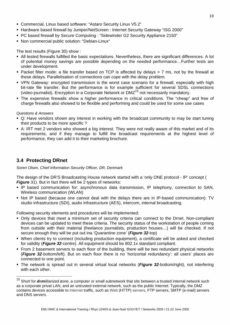
The MIB is organised in a tree structure and every object in this tree is uniquely identified with an object identifier (Figure 18). At the ‘identified organization (3)’ level, any enterprise can have its own object ID . And anything beneath, for example, the ‘BBC (2333) level’ is entirely up to the BBC how to define the objects ID, so that through these unique objects ID one can control the end kit.
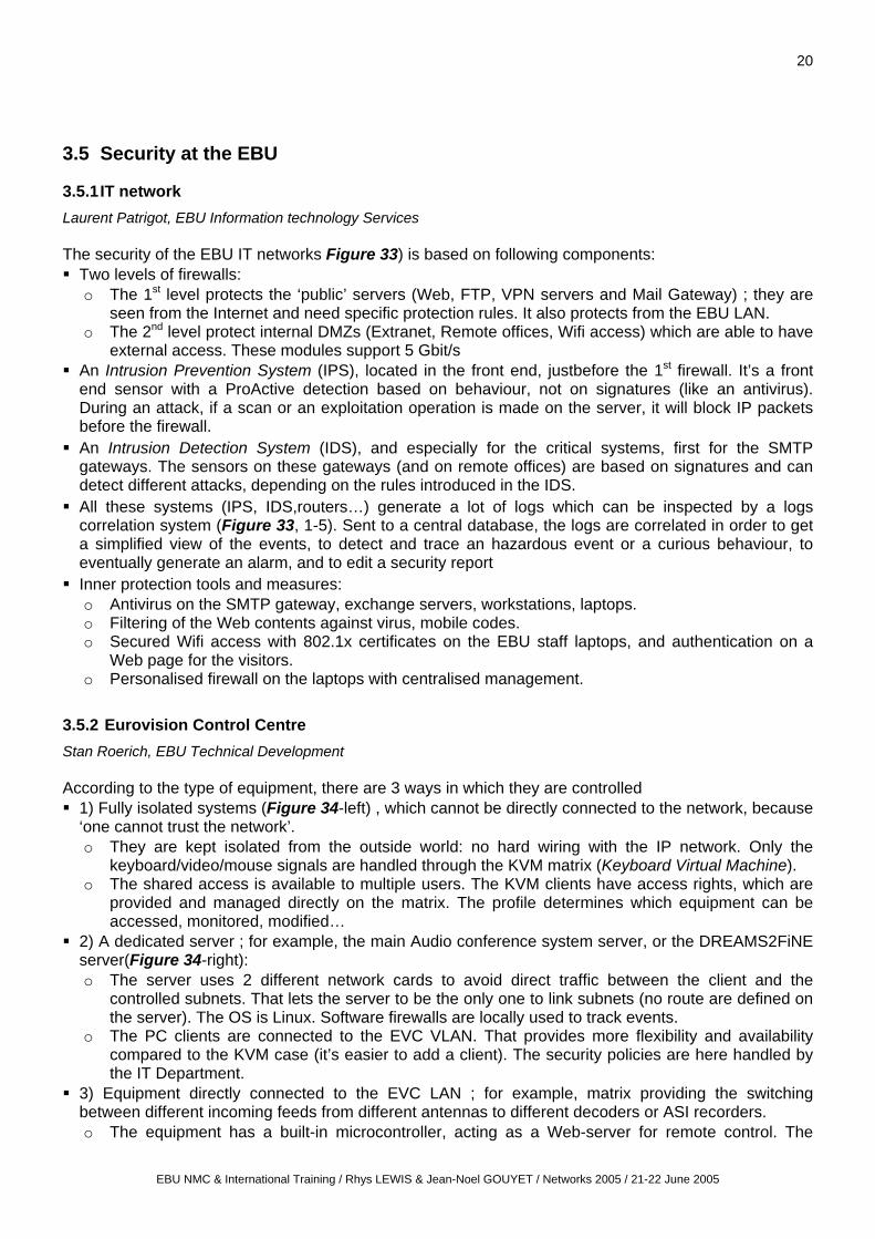
2.3 Common Control Standard for network connected equipment Luke Sluman, BBC R&D The BBC project concerns the replacement in Brodcasting House of the entire traditional live audio structure with a network technology based on ATM and AES 47. This is where the SNMP solution (§ 2.1) comes in to control the end kit, a “BBC radio station in a box” (Figure 19-top). There is one of this box for each radio network and one per output channel (FM, DAB, D-Sat). The Common Control Standard has to define keys covering all the functions to be controlled. So a table lists individually each block of the unit and index it on a simple count (Figure 19-bottom left). An object ID points to another part of the MIB (Figure 19-bottom centre) where the particular functionality to control or monitor is defined (by IEC, EBU, manufacturer). A second table show the imputs for each block (Figure 19-bottom right). For security reasons, SNMP3 offering user authentication, is used. The management calls may then be distinguished according to 4 privilege levels (with a 8-bit number for granularity and avoiding conflicts): Listener (monitoring audio & signals) / Operator (controlling the units) / Supervisor / Maintenance. In order to avoid a lot of network traffic, the BBC project does not use SNMP ‘TRAPS’ to inform thousands of users about the status of the end equipment. Each device broadcasts once its status (like a 7 http://www.ietf.org
EBU NMC & International Training / Rhys LEWIS & Jean-Noel GOUYET / Networks 2005 / 21-22 June 2005

13
teletext page - Figure 20), and it’s up to the network to replicate it (through IP Multicast, for example) to the right control terminal. Questions & Answers Q: To what extent are the manufacturers of broadcast equipment integrating SNMP into their
equipment. If they are not how are you pressuring them to do so ? A: It was easy with small manufacturers for the ATM pilot project. Standard may actually help them.
It’s harder and slower with big manufacturers wanting to sell a complete close system, even if some actually use SNMP to control their network attached suit of products, without telling you. (Markus Berg, IRT): ARD + Deutsche Telekom decided to standardise the control of the DVB-T and DAB transmitters. Main manufacturers joined the group seeing interested in using it (+ ‘We will not buy your equipment if you don’t use it’ !). (Chris Chambers, BBC): Transmitter is a fairly straightforward control mechanism, because it has been well established in the past. There are only 70 functions. Production structure is something else, but there are elements we get in common.
2.4 VRT - Monitoring & controlling Broadcast equipment Marnix Van de Kauter, VRT, Belgium VRT wanted 1 central system manageable by 1 operator to control and monitor all the equipment on its contribution/distribution networks and transmitter sites, with its exotic mixture of elements, interfaces and protocols, in order to get rid of a diversity of management tools with its negative consequences: the difficulty for the operator to work with the different systems; the absence of correlation between events on separate management and monitoring sytems, and the
absence of a central database; the difficulty of maintenance, with the necessity for the maintenance engineers to build up a detailed
knowledge in a broad spectrum of technological specialization. So, during 1,5 years the project was conducted by VRT, assisted by Siemens Belgium8 (time & material contract). The VRT managed this project inspired by the Project Management Institute9 rules and standards. The solution is a management system, being currently implemented, based on 3 engines (Figure 21): The Probe Engine : collects and polls all the states of the parameters on the monitored site,
published then in a MIB table (§ 2.1). Combinations of parameters can define events, and events can trigger actions (e.g., starting timers, the generation of an alarm using SNMP traps, etc…). Interfaces have been implemented to simple relay contacts and digital I/O, field buses (e.g. MODBUS), to serial devices (e.g. SA-Bus, RMCP and other open ASCII-protocols), to TCP/IP protocols (e.g. IIOP) and SNMP proxying.
The GUI Engine: from the topological overview of the country map (Figure 22-left top) one can zoom in and display the block diagram of a site (Figure 22-right). Only the data needed will be collected in real-time from the corresponding probe engine by the SNMP GETs, and immediately translated in updated SVG (scalable vector graphics) objects.
The Alarm Engine: it is based on the Network Node Manager (HP OpenView) and IP Manager (Siemens) for alarm monitoring and handling (Figure 22-left bottom).
Questions & Answers Q: How is the EBU DREAMS control system integrated in your own global control sytem? It is not yet implemented. In the future, we want to get all the DREAMS information in our central
database. Q: What was the purpose for using the PMI rules and standards ?
8 In 2005, Siemens Belgium proposed the commercial product version. Info: [email protected] Tel: +32 14 25 27 32 9 http://www.pmi.org/info/default.asp
EBU NMC & International Training / Rhys LEWIS & Jean-Noel GOUYET / Networks 2005 / 21-22 June 2005

14
A: As we worked closely with a second external partner it was necessary for both project organisations to use common rules and standards for succesful execution of this project. PMI ensures a very high quality of project management.
2.5 TDF - End-to-end QoS monitoring Denis Abraham, Télédiffusion de France Several European projects (Ardor, Danae, Enthrone10, E-Next, Instinct, Wcam…) are working to implement subjective tests and methodologies in order to identify as closely as possible the user satisfaction of Quality, which is the reference of QoS (Figure 23). In a first implementation example, measurement points (MP) are placed in a network at any location where the signal will change of responsibility. All the measurements are connected to a supervision network in order for the network operator to have an overview of the QoS from end-to-end. (Figure 24). A correlation is then established between, for example, Bit Error Rate - Transport Stream (TS) analysis and Video Quality measurements results, in order to monitor and if possible foresee the evolution of the QoS. In order to simplify the management of QoS, 3 parameters representative of the Service performance, directly correlated to the user perception, and derived from the TS analysis have been defined (ETSI ETR290 revision 1 - 9/2000): Service Availability Error, Service Degradation Error, Service Impairments Error11.
3 Security
3.1 Network Security Primer Andy Leigh, Information Security Strategy manager, BBC For most IT security issues, elements more important than TCP/IP security (§ 3.2) need to be considered: Badly specified, designed, installed or operated technologies such as:
o Misconfigured Intermediate Systems (routers, firewalls) o Weak network-glue (DNS, authentication systems) o ‘Old’, not upgraded, flawed or unpatched Operating Systems o Bug-ridden or unpatched applications, databases etc.: most attacks and hacks are against
software and OS, not against the functions of the network. Badly trained and poorly informed end-users and support personnel The attackers themselves, who trigger the need for security.
The simple principles of good security
Never trust a network. So, it does’nt matter that TCP/IP is unsecure (§ 3.2). If you design your system properly, you will not trust the network anyway.
Authenticate everything and everyone: make sure every access is uniquely identified and authenticated; for a lot of production equipment this is definitively not the rule.
Build systems to survive attacks: 802.1x protocol; ensuring systems are well-designed and patches are kept-up to date as is the software and Operating System; no unecessary ports are open. etc. …But all this is still a completely alien concept to many of the people making production and broadcast systems or equipment ; they are not yet ready for the world of attacks as in the IT world.
10 http://www.enthrone.org/ 11 The challenge of QoS for digital television services. EBU Technical Review - April 2005 http://www.ebu.ch/trev_302-abraham.pdf
EBU NMC & International Training / Rhys LEWIS & Jean-Noel GOUYET / Networks 2005 / 21-22 June 2005

15
Do not share resources unless you have to12 o Economy of mechanisms: keep the design as simple and small as possible. o Fail-safe defaults: base access decisions on permission rather than exclusion (“deny all” unless
approved). o Complete mediation: every access to every object checked for authority. o Open design: the design should not be secret. The mechanisms should not depend on the
ignorance of potential attackers, but rather on the possession of specific, more easily protected, keys or passwords.
o Separation of privilege; 2 separate keys (or devices) better than one o Least privilege: every program and every user of the system should operate using the least set of
privileges necessary to complete the job. o Least common mechanism: Minimize the amount of mechanism common to more than one user
and depended on by all users. o Psychological acceptability: it is essential that the human interface be designed for ease of use,
so that users routinely and automatically apply the protection mechanisms correctly.
How hacks happen • Discovery and fingerprinting: scanning the network, doing a bit of ‘Googling’ on Web addresses, trying to find out details and fingerprinting what Operating System you run. • Scanning for vulnerabilities, outdated Operating Systems, ‘holes’. • Analysing and looking for weaknesses • Gaining low-level access, it might be even a simple command line • Escalating to high-level access • Inserting a back-door, so the hacker can log-in afterwards • Cleaning up and exiting Some attacks utilise weak passwords, but many attacks don’t need to know anything about passwords … It’s all over in minutes, sometimes seconds.
3.2 TCP/IP & Security Primer Andy Leigh, Information Security Strategy manager, BBC
3.2.1 General IP/UDP security issues
UDP is “stateless” and is easy to forge. Packets just turn up and could come from anywhere. One knows nothing about its origin … a very dangerous protocol. But it’s needed for one-way media streams and multicast.
•Checksums are not a security technology o Anyone can change the packet details or fake a packet and easily get the CRC correct. There is
no security at all in IP, UDP and TCP headers. o Each router has to change the IP checksum anyway to deal with hopcounts (TTL13)
• IP source addresses are not guaranteed to be correct o Anyone can send a packet with a fake source address o IP addresses are therefore NOT a form of authentication
• IP breaks packets into fragments if they are too big for the link (Figure 25). o Higher-level headers carried only in the first fragment (second fragment may be something
completely different). There have been a number of attacks putting a virus or a port attack into the 2nd packet.
o Only end-stations are allowed to re-assemble. If the attack is against that box, it’s gone before it
12 Saltzer J. H. and Schroeder M.D.The protection of Information in Computer Systems - Basic principles - Design principles. April 1975 http://web.mit.edu/Saltzer/www/publications/protection/ http://cap-lore.com/CapTheory/ProtInf/Basic.html 13 Short for Time to Live, a field in the IP that specifies how many more hops a packet can travel before being discarded or returned.
EBU NMC & International Training / Rhys LEWIS & Jean-Noel GOUYET / Networks 2005 / 21-22 June 2005

16
realised it has been got at…!
3.2.2 TCP specific security issues
TCP states - Denial Of Service (DoS) weaknesses: o An established TCP connection is open “forever” unless keep-alive timers (optional) are invoked.
It’s a handshake (Figure 26). It starts with one side saying ‘Can I join ?’ The other side answers ‘Yes, certainly – by the way here is my handshake back !’There is a 3-way Open and a 4-way Close process. But between each of these states what happens when the process is stuck half the way ? I start to open a connection to a Web site and then my laptop crashes … Does the Web site wait for the rest of the day, expecting the rest of the communication ? If it does, 2 or 3 of these shutdowns and the Web site will be wiped out waiting for things to happen. Therefore there are a number of timers. For example, if you only get half the way to this state, after 75 seconds it drops out.
o A well-known attack against TCP, a few years ago, was to send a handful of opening connections, called SYN attacks - each incoming “SYN” packet hold open on the server a listen-queue connection open for 75 seconds. After 5 or 6 of these packets, the server would hang for about 20 minutes. Most of attacks against TCP involved tripping up the stack and making the server think something is going on. By being able to drop the wrong sort of packets in the wrong place, you can latch up a server or a desktop.
o Double-ended synchronisation is possible. N.B.: these are all “flaws” in the original specification - most real-world Operating Systems have fixed the problems Poor randomisation in the Initial Sequence Number (ISN):
o TCP’s connection invokes at the start of the handshake a “random” Sequence Number which should be hard to guess. This random number was actually designed so that data could not be confused between two connections. But it has a security advantage: somebody else cannot remotely guess the random number of the connection and join in or pretend to join in. It does stop a lot of fake attacks, because the attacker needs to know what these two devices work out as an initial sequence number.
o Unfortunately, in practice many TCP/IP stacks implementations were rubbish at picking random numbers which have been very predictable. Figure 27-left shows a very good one (from the CISCO/IOS, which is the core OS of CISCO routers): the screen is dark grey, because millions and millions of white points (number values) are randomly distributed all over. Figure 27-centre/left: with the OpenVMS (DEC multi-user, multitasking, virtual memory OS on VAX): it will be extremely easy to guess the next sequence number, and so to hijack connections, reset connections and stop the stack. The Mac OSX (Figure 27-centre/right looking like a ‘Milky Way’) is a better attempt to a random distribution. Windows XP (Figure 27-right) is not quite so good…
o TCP-connection spoofing is therefore possible o Connection hijacking o RST Denial Of Service o FIN Denial Of Service Interestingly enough, most modern stacks, Linux, Windows, MacOS are very good and fix these problems. That’s one of the reasons why one cannot afford to have a box with a 3-year old system. And if one has radically different versions and quality of TCP stacks, there are implications for reliability and stability.
3.2.3 Other TCP/IP security issues
Name-spoofing.: pretending to be a well-known address whilst being someone different … Poisoning the names of services is a very good way of attracting towards dangerous sites.
Attacks against routing algorithms (RIP, OPSF…) : pretending to be a router update, you may be able to break bits of the Internet or to break an organisation's internal network if it is not properly secured.
ICMP “Redirect” DoS attack. You send a message to somebody and say 'Please don’t send anymore packets to abc.com! Please send them to yyyyy.com, because abc.com is busy’. This allows the packets, to be sent somewhere unexpected.
ICMP “Destination Unreachable” DoS attack : ‘microsoft.com unavailable’, for example!
EBU NMC & International Training / Rhys LEWIS & Jean-Noel GOUYET / Networks 2005 / 21-22 June 2005

17
SNMP. A management interface where the information travels in in clear text: Sticking a network analyzer on the network running SNMP, one captures the security string and can then drop in freeware tools or packets to go onto one of the transmitters… An attack is very easy with SNMP V.1 & V.2. SNMP V.3 encrypts the data; so it becomes very difficult to work out what these communities strings are.
ARP spoofing (or poisoning): technique used to sniff frames on a switched LAN or to stop the traffic on the LAN by.sending fake ARP replies ($ 1.1.1) to the LAN. Frames intended for one machine can be mistakenly sent to another one (allowing IP packets, SNMP packets, FTP addresses… to be sniffed) or to an unreachable host (denial-of-service).
3.2.4 Solutions to TCP/IP’s problems
Completely fix TCP/IP by re-writing it! Move to IPv6: it’s the proper technology to fix the problems, with Authentication Header, ESP and
Encryption Header …The only problem is that there is no good financial reason to move towards version 6 …
Use IPSec14 to secure point-to-point connections. VPNs use a technology to encrypt the IP headers and authenticate the packets themselves. Looks remarkably similar to IPv6 security solutions (AH, ESP), but runs on the existing IP.and it’s pretty strong.
“Harden” any common equipment & use application-level protection (e.g. SSL) – And follow good security operational practices Build layered security using choke-points (e.g. using firewalls) …
Firewalls As already indicated in the IP ‘light’ refresher (§ 1.1.1), the routers have no way in knowing whether the IP packet is valid, assuming it has not been broken in somewhere. This has a lot of influence on how one designs security. So, putting firewalls on the network is completely pointless. You have to put filters and decision-making devices on the receiving end system, or as close as possible. This is why the 802.1x protocol is so much better with a couple of firewalls than a firewall on the edge of the network, which is not the future. Having distributed firewalls at far end (§ 3.3) is also a very good strategy. Positives
o Stateful filtering firewalls: watch the ‘state’ of any connections to ensure they are valid (they look at the state diagram and say ‘None of this makes sense - I’m rejecting the packets’). Can prevent most network attacks.
o Proxy firewalls: don’t pass through-packets (if well-built, are impervious to network attacks). They communicate application-to-application.
Negatives o Firewalls cannot stop application-level attacks against a weak application. o They affect performance … but it’s getting better (§ 3.3) o Secure rules are sometimes impossible in real-world (one cannot build a firewall for UDP, this is
hopelessly unsecure). o They don’t prevent snooping
3.2.5 Conclusions
Packet networks are inherently less secure than the traditional switched circuit networks (Figure 28). There’s a great deal more to security than secure networking. Network attacks are usually in the
minority. Most attacks are against weak software, applications and OS. The basic principles of good security:
o Never trust a network o Always authenticate every transaction o Build systems to survive attacks
IP and associated protocols have a number of security flaws TCP has a number of inherent known security flaws (most of which have been mitigated by most real-
14 Short for IP Security, a set of protocolsdeveloped by theIETF to support secure exchange of packets at the IP layer. IPsec has been deployed widely to implement Virtual Private networks (VPN).
EBU NMC & International Training / Rhys LEWIS & Jean-Noel GOUYET / Networks 2005 / 21-22 June 2005

18
world implementations) Firewalls, hardening, IPv6 and encrypting the packets can help. Keep the OS up-to-date and well
patched. Good security is essential, but there are potential impacts on performance. Broadcasters must agree amongst themselves which good security standards they can adopt. Questions & Answers Q: Is it practical for engineers to go about to try to diagnose stacks problems ? Is it something we can
tell the vendors to fix them. A: It is something we cannot expect general users and operational staff to understand. It requires
knowledge and years of experience. There are specialists who can supply this service. Where there is any doubt or any concern, it’s worth first putting in place contracts when purchasing systems, to ensure that the supplier will guarantee that their stacks are up-to-date, and that their implementations meet current known working practices and standards.
Q: About the necessity to keep software and OS up-to-date. In the Broadcast environment one meets a lot of resistance to make any change to a system. What is the best way to deal with resistances ?
A: Educate, convince by having clear argument, demonstrate there is a justification for this…If people insist thet they are not to patch their kit, start to ask them about their own home system: Have they a firewall, an antivirus, security packs, automatic OS update … ? Ultimately, if I cannot convince, I build a ring around this particular kit to protect the rest of the infrastructure. But one has to get earlier and earlier in the design stage. Updating is part of the requirement specifications from suppliers and support organisations. This is not a short-term fix, this is a long-term win.
3.3 Secured Network Performance & firewalls tests Markus Berg, Head of Broadcast Networks & Servers Department (+Herbert Guist and Matthias Hammer), IRT, Germany Due to the increasing use of IT based equipment and high speed networks, broadcasters experience a growing need for network security. Therefore, the Institut für Rundfunktechnik in Munich (IRT) carried out a project on security in contribution and distribution networks of broadcasters with a special focus on the performance of different types of firewalls. Firewalls are used to secure diverse parts of Broadcast networks (Figure 29): Internet connections, secured by “classical” firewall configurations (including VPN); Intranet and production, for securing critical internal departments like: archives, production, playout,
administration… Corporate Network, regional networks, connections to partners; separation of ‘office’- traffic and ,for example, video file transfer.
For the video file transfer, for example, specific requirements for broadcast apply to firewalls: ‘Small’ number of data streams at very high speed
o Copying files in a production LAN o Video file transfer in the corporate network o Requirement: data streams up to 600 Mbit/s
Due to the huge file size (200-400 MByte/minute), proyxs with virus protection are no solution IPsec VPN-connections… are considered secure today. But as the broadcasters requirements are
also valid for VPN traffic (i.e. file transfer from external organisations), the VPN performance also had to be validated.
In order to gain experience on the performance of firewalls with respect to the broadcasters' requirements (no references available up to now), the IRT has tested 4 different types of firewalls:
EBU NMC & International Training / Rhys LEWIS & Jean-Noel GOUYET / Networks 2005 / 21-22 June 2005
19
Commercial, Linux based software: “Astaro Security Linux V5.2” Hardware based firewall by Juniper/NetScreen : Internet Security Gateway “ISG 2000” PC based firewall by Secure Computing : “Sidewinder G2 Security Appliance 2150” Non commercial public solution: “Debian-Linux“
The test results (Figure 30) show : All tested firewalls fulfilled the basic expectations. Nevertheless, there are significant differences. A lot
of potential money savings are possible depending on the needed performance…Further tests are under development.
Packet filter mode: a file transfer based on TCP is affected by delays > 7 ms, not by the firewall at these delays. Parallelisation of connections can cope with the delay problem.
VPN Gateway: encrypted transmission is the worst case scenario for a firewall, especially with high bit-rate file transfer. But the performance is for example sufficient for several SDSL connections (video-journalist). Encryption in a Corporate Network or DMZ15 not necessarily mandatory.
The expensive firewalls show a higher performance in critical conditions. The “cheap” and free of charge firewalls also showed to be flexible and performing and could be used for some use cases
Questions & Answers Q: Have vendors shown any interest in working with the broadcast community to may be start tuning
their products to be more specific ? A: IRT met 2 vendors who showed a big interest. They were not really aware of this market and of its
requirements, and if they manage to fulfill the broadcast requirements at the highest level of performance, they can add it to their marketing brochure.
3.4 Protecting DRnet Soren Olsen, Chief Information Security Officer, DR, Denmark The design of the DR’S Broadcasting House network started with a ‘only ONE protocol - IP’ concept ( Figure 31). But in fact there will be 2 types of networks: IP based communication for: asynchronous data transmission, IP telephony, connection to SAN,
Wireless communication (WLAN) Not IP based (because one cannot deal with the delays there are in IP-based communication): TV
studio infrastructure (SDI), audio infrastructure (AES), intercom, internal broadcasting. Following security elements and procedures will be implemented: Only devices that meet a minimum set of security criteria can connect to the Drnet. Non-compliant
devices can be updated to meet these criteria. The security status of the workstation of people coming from outside with their material (freelance journalists, production houses…) will be checked. If not secure enough they will be put out ina ‘Quarantine zone’ (Figure 32-top)
When clients try to connect (including production equipment), a certificate will be asked and checked for validity (Figure 32-centre). All equipment should be 802.1x standard compliant.
From 2 basement servers to each floor of the building, there will be two redundant physical networks (Figure 32-bottom/left). But on each floor there is no ‘horizontal redundancy’: all users’ places are connected to one point.
The network is spread out in several virtual local networks (Figure 32-bottom/right), not interfering with each other.
15 Short for demilitarized zone, a computer or small subnetwork that sits between a trusted internal network such as a corporate privat LAN, and an untrusted external network, such as the public Internet. Typically, the DMZ contains devices accessible to Internet traffic, such as Web (HTTP) servers, FTP servers, SMTP (e-mail) servers and DNS servers.
EBU NMC & International Training / Rhys LEWIS & Jean-Noel GOUYET / Networks 2005 / 21-22 June 2005
20
3.5 Security at the EBU
3.5.1 IT network Laurent Patrigot, EBU Information technology Services The security of the EBU IT networks Figure 33) is based on following components: Two levels of firewalls:
o The 1st level protects the ‘public’ servers (Web, FTP, VPN servers and Mail Gateway) ; they are seen from the Internet and need specific protection rules. It also protects from the EBU LAN.
o The 2nd level protect internal DMZs (Extranet, Remote offices, Wifi access) which are able to have external access. These modules support 5 Gbit/s
An Intrusion Prevention System (IPS), located in the front end, justbefore the 1st firewall. It’s a front end sensor with a ProActive detection based on behaviour, not on signatures (like an antivirus). During an attack, if a scan or an exploitation operation is made on the server, it will block IP packets before the firewall.
An Intrusion Detection System (IDS), and especially for the critical systems, first for the SMTP gateways. The sensors on these gateways (and on remote offices) are based on signatures and can detect different attacks, depending on the rules introduced in the IDS.
All these systems (IPS, IDS,routers…) generate a lot of logs which can be inspected by a logs correlation system (Figure 33, 1-5). Sent to a central database, the logs are correlated in order to get a simplified view of the events, to detect and trace an hazardous event or a curious behaviour, to eventually generate an alarm, and to edit a security report
Inner protection tools and measures: o Antivirus on the SMTP gateway, exchange servers, workstations, laptops. o Filtering of the Web contents against virus, mobile codes. o Secured Wifi access with 802.1x certificates on the EBU staff laptops, and authentication on a
Web page for the visitors. o Personalised firewall on the laptops with centralised management.
3.5.2 Eurovision Control Centre Stan Roerich, EBU Technical Development According to the type of equipment, there are 3 ways in which they are controlled 1) Fully isolated systems (Figure 34-left) , which cannot be directly connected to the network, because
‘one cannot trust the network’. o They are kept isolated from the outside world: no hard wiring with the IP network. Only the
keyboard/video/mouse signals are handled through the KVM matrix (Keyboard Virtual Machine). o The shared access is available to multiple users. The KVM clients have access rights, which are
provided and managed directly on the matrix. The profile determines which equipment can be accessed, monitored, modified…
2) A dedicated server ; for example, the main Audio conference system server, or the DREAMS2FiNE server(Figure 34-right): o The server uses 2 different network cards to avoid direct traffic between the client and the
controlled subnets. That lets the server to be the only one to link subnets (no route are defined on the server). The OS is Linux. Software firewalls are locally used to track events.
o The PC clients are connected to the EVC VLAN. That provides more flexibility and availability compared to the KVM case (it’s easier to add a client). The security policies are here handled by the IT Department.
3) Equipment directly connected to the EVC LAN ; for example, matrix providing the switching between different incoming feeds from different antennas to different decoders or ASI recorders. o The equipment has a built-in microcontroller, acting as a Web-server for remote control. The
EBU NMC & International Training / Rhys LEWIS & Jean-Noel GOUYET / Networks 2005 / 21-22 June 2005

21
microcontroller is less sensitive to external attacks, because it’s quite simple ; when attacked, it may freeze but never breaks down. It also requires less intervention (very few update).
o In case of freeze of the equipment controller, a reset can be done without stopping the operational functions. The status of the matrix will be kept, and only 20 sec. of control are lost.
o There are 2 controllers for each equipment for redundancy. o A back-up access is provided by a dedicated, isolated (from the EVC LAN) client, acting as a
gateway with the KVM matrix. Remote access is needed for a huge part of this controlled equipment: for field operation, or for the support team (diagnostic from home): Equipment connected to the EVC LAN can be accessed through a VPN in-house application. For isolated equipment (on KVM), a temporary connection is established on request through a KVM/IP
gateway (between the EVC LAN and and the KVM clients).
Annex Figure 1 : So, just what is IP?
Figure 2 : Wrapping up packets
Figure 3 : How does an IP packet get from here to there
Source: BBC Technology Direction Figure 4: SVT WAN topology - Final solution
Source: Sveriges Television
Figure 5 : BBC 2003 WAN trial results
Figure 6 : BBC hybrid network = Raman core + site clusters
Figure 7 : BBC Raman core typical deployment
Source: BBC, Technology Direction
Figure 8 : ’Classical’ SDH Multiplexing
Figure 9 :NG-SDH and Virtual Concatenation
Figure 10 : GFP-F mapping of DVB-ASI signals
Source: RAI
Figure 11 : Evolution of the network towards NG-SDH
Figure 12 : Generic Framing Procedure
Figure 13 : DTM as a convergence layer
Figure 14 : Evolution of the RAI network capacity allocation
Source: RAI
Figure 15 : Functional overview of WDR RegioNet
Source: WDR
Figure 16 : MusiPOP
Source: EBU EuroRadio
EBU NMC & International Training / Rhys LEWIS & Jean-Noel GOUYET / Networks 2005 / 21-22 June 2005

22
Figure 17 : Main components of a Simple Network Management Protocol
Figure 18 : SNMP basic tree of the Management Information Base and objects identifiers
Figure 19 : BBC SNMP-controlled radio station in a box
Figure 20 : BBC equipment status broadcast
Source: BBC R&D
Figure 21 : VRT Transmission Control sytem architecture
Figure 22 : VRT Transmission Control user interface
Source: VRT + Siemens Belgium
Figure 23 :Proposed reference QoS framework
Figure 24 : End-to-end QoS overview
Source: TDF
Figure 25 : IP fragmentation
Figure 26 : The TCP finite-state-machine
Figure 27 : Real-world Initial Sequence ‘random’ numbers
Figure 28 : Comparison of security features betwwen circuits- and packets-based circuits
Source: BBC, Technology Direction
Figure 29 : Example of firewalls in Broadcast networks
Figure 30 : Firewalls test results
Source: IRT
Figure 31 : Principles for an IT-based TV production in DR = ‘All on ONE horse’
Figure 32 : DRnet security elements and procedures
Source: DR Figure 33 : EBU Global IT architecture and security
Figure 34 : EBU EVCsecurity
Source: EBU
EBU NMC & International Training / Rhys LEWIS & Jean-Noel GOUYET / Networks 2005 / 21-22 June 2005

23
Abbreviations and acronyms
AAC Advanced Audio Coding LWL Long WaveLength AAF Advanced Authoring Format MAN Metropolitan Area Network ADM Add-Drop Multiplexer (SDH) MPEG Moving Picture Experts Group ADSL Asymmetrical Digital Subscriber Line MIB Management Information Base (SNMP) AH Authentication Header ML Main Level (MPEG-2) API Application Programming Interface MPLS Mulkti-Protocol Label Switching ARP Address Resolution Protocol (Internet) MXF Material eXchange Format ASI Asynchronous Serial Interface (DVB) NAS Network Attached Storage ATM Asynchronous Transfer Mode NG-SDH Next Generation - SDH AVC Advanced Video Coding OSPF Open Shortest Path First BGP Border Gateway Protocol (Internet) OS Operating System BER Bit Error Rate POH Path Overhead (SDH) BWF Broadcast Wave Format POP Post Office Protocol (Internet e-mail) C/DWDM Coarse/Dense Wave Division Multiplexing POP Point of presence CGI Common Gateway Interface PDH Plesiochronous Digital Hierarchy CRC Cyclic Redundancy Check QoS Quality of Service DAB Digital Audio Broadcasting RIP Raman Interconnect Point DMZ DeMilitarised Zone RIP Routing Information Protocol (Internet) DNS Domain Name System (or Service, or Server) RIP Raman Interconnect Point DoS Denial-of-service attack RSVP Resource reSerVation Protocol (Internet) DTM Dynamic synchronous Transfer Mode RTCP Real-Time Control Protocol (Internet) DTTB Digital Terrestrial Television Broadcasting RTSP Real-Time Streaming Protocol (Internet) DVB Digital Video Broadcasting RTP Real-time Transport Protocol (Internet) DWDM Dense Wave Division Multiplexing SAN Storage Area Network DXC Digital Cross Connect (SDH) SBR Side Band Replication E1 European PDH system level 1 (2.048 Mbit/s) SDI Serial Digital Interface (270 Mbit/s) ESP Encapsulating Security Payload SD(TV) Standard Definition (Television) FC Fibre Channel SDH Synchronous Digital Hierarchy FEC Forward Error Correction SDSL Single line Digital Subscriber Line FLAC Free Lossless Audio Codec SMTP Simple Mail Transfer Protocol FTP File Transfer Protocol (Internet) SNMP Single Network Management Protocol GbE Gigabit Ethernet SQL Structured Query Language GFP Generic Framing Procedure (NG-SDH) SSL Secure Socket Layer GUI Graphical User Interface STB Set-top box (récepteur-décodeur numérique) HD(TV) High-Definition (Television) STM-1 Synchronous Transport Module Level 1 (155 Mbit/s) HTTP HyperText Transfer Protocol STM-4 Synchronous Transport Module Level 4 (622 Mbit/s) ICMP Internet Control Message Protocol (Internet) STM-16 Synchronous Transport Module Level 16 (2,5 Gbit/s) ID Identifier, identification STM-64 Synchronous Transport Module Level 64 (10 Gbit/s) IDS Intrusion DetectionSystem SVG Scalable Vector Graphics IETF Internet Engineering Task Force TCP Transmission Control Protocol (Internet) IP Internet Protocol TS Transport Stream (MPEG-2) IPS Intrusion Prevention System TTL Time to Live IPsec IP Security UDP User Datagram Protocol (Internet) ISN Initial Sequence Number VC Virtuial Container (SDH) ISO International Organization for Standardization VCAT Virtual Concatenation (NG-SDH) ISP Internet Service Provider VPN Virtual Private Network IT Information Technology (‘informatique’) WAN Wide Area Network KVM Keyboard Virtual Machine WLAN Wireless LAN LAN Local Area Network XML eXtensible Mark-up Language
EBU NMC & International Training / Rhys LEWIS & Jean-Noel GOUYET / Networks 2005 / 21-22 June 2005

Networks 2005 report
Annex Figure 1 : So, just what is IP?
Figure 2 : Wrapping up packets
Figure 3 : How does an IP packet get from here to there
Source: BBC Technology Direction

Figure 4: SVT WAN topology - Final solution
Source: Sveriges Television Figure 5 : BBC 2003 WAN trial results

Figure 6 : BBC hybrid network = Raman core + site clusters
Oxford
Cluster
GW
BE
CF
BS
BM
LS
NT
HU/L
NC
CB/L
TWS
SO
PY
NO
EH
MK
OF/L
W12 W1
DRC
MR
North
RIP
South
RIP
So’t’n
Cluster
Welsh
Cluster
Bristol
Cluster
Tunbridge Wells
Cluster
LFN W1 and W12 Villages
Plymouth
Cluster
S E Mids
Cluster
W Mids
Cluster
North
ClusterN West
Cluster
N Ireland
Cluster
Scotland
ClusterN East
Cluster
Oxford
Cluster
GW
BE
CF
BS
BM
LS
NT
HU/L
NC
CB/L
TWS
SO
PY
NO
OF/L
W12 W1
DRC
EH
MK
MR
North
RIP
South
RIP
So’t’n
Cluster
Welsh
Cluster
Bristol
Cluster
Tunbridge Wells
Cluster
LFN W1 and W12 Villages
Plymouth
Cluster
S E Mids
Cluster
W Mids
Cluster
North
ClusterN West
Cluster
N Ireland
Cluster
Scotland
ClusterN East
Cluster
Figure 7 : BBC Raman core typical deployment
RIP South
E’netE’net
E’netE’net
MUXMUX
MUXMUX
VisionSwitch
ATMSwitch
NetworkMgmt
System
RIP North
MUX MUX
iLynx iLynx
TC
ASX ASX
MUX MUX
iLynx iLynx
BM
ASX ASX
E’netE’net
E’netE’net
MUXMUX
MUXMUX
VisionSwitch
ATMSwitch
NetworkMgmt
System
Each site typically has :•4 x 1 GbE (Ethernet) x 2•2.5Gbit/s for real time circuits x 2(Scientific Atlanta iLynx with SDI, ASI, PAL interfaces)
•1 x STM-1 (155 Mbit/s) x 2 for legacy ATM services and audio AES47(Marconi ASX switch)
RIP South
E’netE’net
E’netE’net
MUXMUX
MUXMUX
VisionSwitch
ATMSwitch
NetworkMgmt
System
RIP North
MUX MUX
iLynx iLynx
TC
ASX ASX
MUX MUX
iLynx iLynx
BM
ASX ASX
E’netE’net
E’netE’net
MUXMUX
MUXMUX
VisionSwitch
ATMSwitch
NetworkMgmt
System
RIP South
E’netE’net
E’netE’net
MUXMUX
MUXMUX
VisionSwitch
ATMSwitch
NetworkMgmt
System
E’netE’net
E’netE’net
MUXMUX
MUXMUX
VisionSwitch
ATMSwitch
NetworkMgmt
System
RIP North
MUX MUX
iLynx iLynx
TC
ASX ASX
MUX MUX
iLynx iLynx
TC
ASX ASX
MUX MUX
iLynx iLynx
BM
ASX ASX
E’netE’net
E’netE’net
MUXMUX
MUXMUX
VisionSwitch
ATMSwitch
NetworkMgmt
System
Each site typically has :•4 x 1 GbE (Ethernet) x 2•2.5Gbit/s for real time circuits x 2(Scientific Atlanta iLynx with SDI, ASI, PAL interfaces)
•1 x STM-1 (155 Mbit/s) x 2 for legacy ATM services and audio AES47(Marconi ASX switch)
Source: BBC, Technology Direction

Figure 8 : ’Classical’ SDH Multiplexing
Figure 9 :NG-SDH and Virtual Concatenation
Figure 10 : GFP-F mapping of DVB-ASI signals
Source: RAI

Figure 11 : Evolution of the network towards NG-SDH
Figure 12 : Generic Framing Procedure
Figure 13 : DTM as a convergence layer

Figure 14 : Evolution of the RAI network capacity allocation
Source: RAI
Figure 15 : Functional overview of WDR RegioNet
Source: WDR
Figure 16 : MusiPOP
Source: EBU EuroRadio
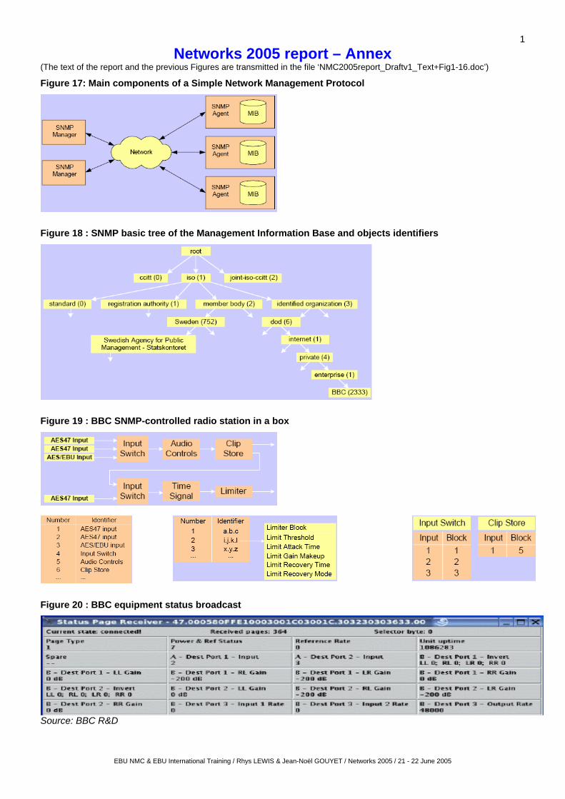
1
EBU NMC & EBU International Training / Rhys LEWIS & Jean-Noël GOUYET / Networks 2005 / 21 - 22 June 2005
Networks 2005 report – Annex (The text of the report and the previous Figures are transmitted in the file ‘NMC2005report_Draftv1_Text+Fig1-16.doc’)
Figure 17: Main components of a Simple Network Management Protocol
Figure 18 : SNMP basic tree of the Management Information Base and objects identifiers
Figure 19 : BBC SNMP-controlled radio station in a box
Figure 20 : BBC equipment status broadcast
Source: BBC R&D

2
EBU NMC & EBU International Training / Rhys LEWIS & Jean-Noël GOUYET / Networks 2005 / 21 - 22 June 2005
Figure 21 : VRT Transmission Control sytem architecture
Figure 22 : VRT Transmission Control user interface
Source: VRT + Siemens Belgium

3
EBU NMC & EBU International Training / Rhys LEWIS & Jean-Noël GOUYET / Networks 2005 / 21 - 22 June 2005
Figure 23 :Proposed reference QoS framework
Sourcemedia
Applicatione.g. streaming over UMTS,
Parameters influencing QoS- source coding parameters
(datarate, resolution, …)- transmission parameters
(bandwidth, packet loss, BER, jitter…)- terminal parameters (screen features,
outdoor use)
Related parameters- frame rate- blockiness measurement- drop out- blur- media contents (spatial & temporal activity)
Perceived QoS 1 0 0
8 0
6 0
4 0
2 0
0
E x c e l le n t
G o o d
F a i r
P o o r
B a d
Gold
Silver
Bronze
(text, audio-video,remote command …)
Context
Sourcemedia
Applicatione.g. streaming over UMTS,
Parameters influencing QoS- source coding parameters
(datarate, resolution, …)- transmission parameters
(bandwidth, packet loss, BER, jitter…)- terminal parameters (screen features,
outdoor use)
Related parameters- frame rate- blockiness measurement- drop out- blur- media contents (spatial & temporal activity)
Perceived QoS 1 0 0
8 0
6 0
4 0
2 0
0
E x c e l le n t
G o o d
F a i r
P o o r
B a d
Gold
Silver
Bronze
1 0 0
8 0
6 0
4 0
2 0
0
E x c e l le n t
G o o d
F a i r
P o o r
B a d
Gold
Silver
Bronze
(text, audio-video,remote command …)
Context
Figure 24 : End-to-end QoS overview
Source: TDF
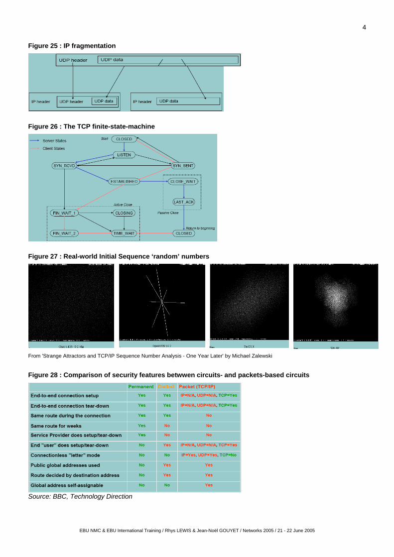
4
EBU NMC & EBU International Training / Rhys LEWIS & Jean-Noël GOUYET / Networks 2005 / 21 - 22 June 2005
Figure 25 : IP fragmentation
Figure 26 : The TCP finite-state-machine
Figure 27 : Real-world Initial Sequence ‘random’ numbers
From 'Strange Attractors and TCP/IP Sequence Number Analysis - One Year Later' by Michael Zalewski
Figure 28 : Comparison of security features betwwen circuits- and packets-based circuits
Source: BBC, Technology Direction

5
EBU NMC & EBU International Training / Rhys LEWIS & Jean-Noël GOUYET / Networks 2005 / 21 - 22 June 2005
Figure 29 : Example of firewalls in Broadcast networks
Figure 30 : Firewalls test results
(* No VPN test possible due to current new implementation of AES encryption - tests will be performed later) 1 x High-Performance throughput (Mbit/s) through 2 firewalls in Packet-Filter and VPN (with encryption) mode, simulating a video file transfer on a single TCP connection between endpoints.
1 x High-Performance Throughput (Mbit/s) through 2 firewalls in Packet-Filter and VPN mode
50-parallel connections High-Performance Throughput (Mbit/s) through 2 firewalls in Packet-Filter and VPN mode at 40 ms delay, simulating a high number of file transfers at the same time.
TCP/IP video file transfer rate 5Mbit/s) test using the DAVID Replikator Software ¹ Transmission very symmetric and stable ² Transmission with constant interruptions * A large number of interruptions, no useful measurement possible
Source: IRT

6
EBU NMC & EBU International Training / Rhys LEWIS & Jean-Noël GOUYET / Networks 2005 / 21 - 22 June 2005
Figure 31 : Principles for an IT-based TV production in DR = ‘All on ONE horse’
The Media Factory DR
Continuity
Master Control(TC)
Digital ArchiveProgram Dep. B
Program Dep. C
Program Dep. D
SAN
LAN (G-bit)
DSNG
OB-production
ExternalTapes
WANMPEG 2
Desk-Topediting andConfirming
Desk-Topediting andConfirming
ETSI34 Mbit
Satellite
Internetfile transfer
Conversion to"factory-format"
On-lineed it
D esk-T oped it
Play-out Server
Hard D isk Archive D atatape Archive
D esk -T opedit ing On-line
edit ing
MPEG c oder
Principles for IT-based TV- Production in DRVersion 9 March 2003
EFP-production
ETSI coder
MPEG c oder
Satellite DVB-S 2 x 8 Mbit + R
Terrestrial PAL v ia DVB-S
On-Line 155 Mbit connec tionto ISP
Analog Link
ENGVans
Terrestrial DVB-T via DVB-S
Tape/Link
Tape
Production NetworkTCP/IP
Lap-Topediting
Tape / RAM / DiskFire Wire / LAN
AVIM-JPEGDVDVCPRODVCam
Conv. from"factory-format"
Contribution formats
Dis tribution formats
Jørn Tuxen12/3-2003
F
F
F
F
F
F
FF
F = Factory format(DIF/MXF file format)
B rowsi ng
M peg 1
OB, ENG, EFP
Mpeg
EBUReuter
APand
othersPAL
Mpeg
Production Dep. A
Live-prod.and Editing Studios
SDI-Ma trix
S tudio
serverserver
SDI-streaming
SDI
Desk-Top editingand Confirming
Conv. to"factory-format"
News Department
Graphic andtrailer production
Graphiced itOn-line
edit
F
F
Legacy IngestFilm scanner
Color correction(BF)
Mixer
F
loc alInges t
Ingest
In ge st
Ingest
Ingest

7
Figure 32 : DRnet security elements and procedures
Access granting process
Client and Switch talking 802.1x Switch talking with Auth Server via RADIUSClient and Switch talking 802.1xClient and Switch talking 802.1x Switch talking with Auth Server via RADIUSSwitch talking with Auth Server via RADIUS
Identity based networking services (IBNS)
Fonction :
Network vertical redundancy
SRV1
Krydsfelt
VLAN11
VLAN21
VLAN31
UserAccess
UserDistribution
VLAN12
VLAN22
VLAN32
SRV2
L3
L2
Distribution frame
L3
L2
Distribution frame
Layered distribution
Source: DR
EBU NMC & EBU International Training / Rhys LEWIS & Jean-Noël GOUYET / Networks 2005 / 21 - 22 June 2005

8
Figure 33 : EBU Global IT architecture and security
Figure 34 : EBU EVCsecurity
Fully isolated systems
Dedicated server
Source: EBU
EBU NMC & EBU International Training / Rhys LEWIS & Jean-Noël GOUYET / Networks 2005 / 21 - 22 June 2005