Embed Size (px)
Citation preview
Networking Standards and the OSI Model

Networking Standards Organizations
2
StandardDocumented agreement containing technical
specificationsStipulates design or performance of particular
product or serviceWhere would we be without standards?
Standards are essential in the networking worldWide variety of hardware and software
Ensures network design compatibility
Standards define minimum acceptable performance
Networking Standards Organizations (cont’d.)
3
Many different organizations oversee computer industry standardsOrganizations may overlap responsibilities
Example: ANSI and IEEE set wireless standardsANSI -> kind of NICIEEE -> how communication gets there

ANSI
4
ANSI (American National Standards Institute)1000+ representatives from industry and
governmentDetermines standards for electronics industry
and other fieldsRequests voluntarily compliance with
standardsObtaining ANSI approval requires rigorous
testingwww.ansi.org
IEEE
5
IEEE (Institute of Electrical and Electronics Engineers)
Goal of IEEEPromote development and education in
electrical engineering and computer science fields
Maintains a standards board that establishes its own standards and works with ANSI
IEEE technical papers and standards are highly respected (www.ieee.org)
ISO
6
ISO (International Organization for Standardization)Headquartered in Geneva, SwitzerlandCollection of standards organizations
Representing 57 countries
Goal of ISO Establish international technological standards
to facilitate global exchange of information and barrier free trade
Widespread authorityNot limited to just communications (ex.
banking)

EIA and TIA
7
EIA (Electronic Industries Alliance)Trade organization
Representatives from United States electronics manufacturing firms
Lobbies for favorable computer and electronics industries legislation
TIA (Telecommunications Industry Association)Focus of TIA
Standards for information technology, wireless, satellite, fiber optics, and telephone equipment
TIA/EIA 568-B SeriesGuidelines for installing network cable in commercial
buildings
ITU
8
ITU (International Telecommunication Union)Specialized United Nations agencyRegulates international telecommunications
Focus of ITUGlobal telecommunications issuesWorldwide Internet services implementation

ISOC
9
ISOC (Internet Society)Founded in 1992Establishes technical Internet standards
ISOC oversees groups with specific missionsIETF (Internet Engineering Task Force)
Sets Internet system communication standardsParticularly protocol operation and interactionAnyone may submit standard proposalElaborate review, testing, and approval processes

IANA and ICANN
10
IANA (Internet Assigned Numbers Authority) and ICANN (Internet Corporation for Assigned Names and Numbers)
IP (Internet Protocol) addressAddress identifying computers in TCP/IP
based (Internet) networksReliance on centralized management
authoritiesIP address management history
Initially: IANA (Internet Assigned Numbers Authority)

IANA and ICANN (cont’d.)
11
IP address management history (cont’d.)Late 1990s: ICANN (Internet Corporation for
Assigned Names and Numbers) took overPrivate nonprofit corporationRemains responsible for IP addressing and domain
name managementIANA performs system administration
Users and business obtain IP addresses from ISP (Internet service provider) who get it from regional internet registries (RIR) who ultimately get it from ICANN
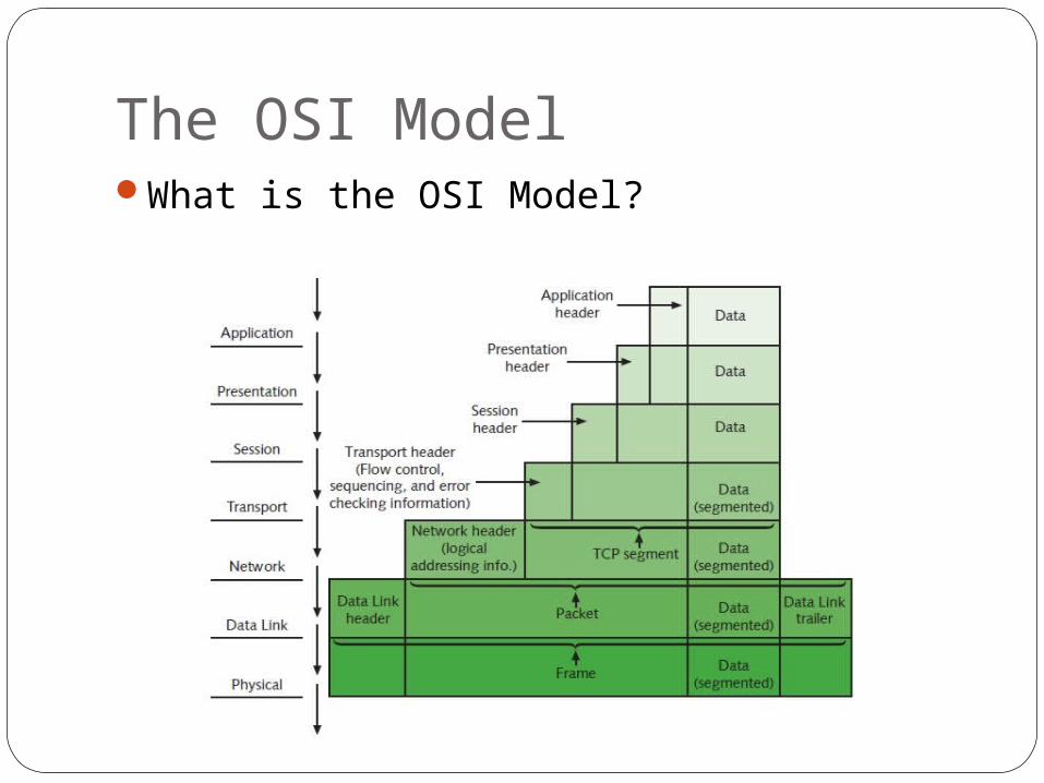
The OSI ModelWhat is the OSI Model?

The OSI Model
13
Model for understanding and developing network computer-to-computer communications
Developed by ISO (1980s)OSI (Open Systems Interconnection Model)Divides network communications into
seven layersPhysical, Data Link, Network, Transport,
Session, Presentation, Application
The OSI Model (cont’d.)
14
Protocol interactionProtocols interact with layer directly above
and belowApplication layer protocols (top)
Interact with software (ex. MS Word)Physical layer protocols (bottom)
Act on cables and connectors (UTP Cable)

The OSI Model (cont’d.)
15
Theoretical representation describing network communication between two nodes
Hardware and software independentEvery network communication process is
representedPDUs (protocol data units)
Discrete amount of dataApplication layer functionFlow through layers 6, 5, 4, 3, 2, and 1
Generalized model Sometimes imperfect
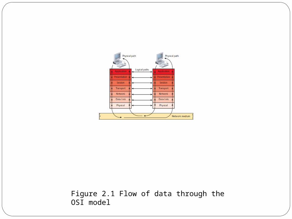
16
Figure 2.1 Flow of data through the OSI model

Application Layer
17
Top (seventh) OSI model layerNo software applications hereProtocol functions
Facilitates communication between software applications and lower-layer network services
Network interprets application requestApplication interprets data sent from network
Software applications negotiate with application layer protocolsFormatting, procedural, security,
synchronization, and other requirements
Presentation Layer
18
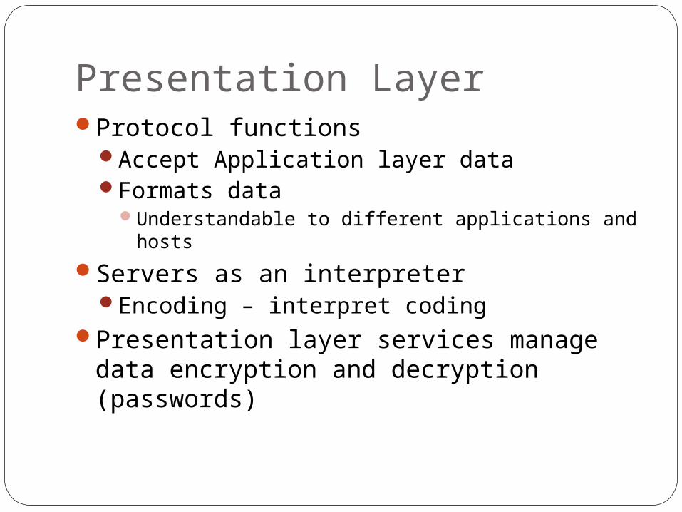
Protocol functionsAccept Application layer dataFormats data
Understandable to different applications and hosts
Servers as an interpreterEncoding – interpret coding
Presentation layer services manage data encryption and decryption (passwords)

Session Layer
19
Protocol functionsCoordinate and maintain communications
between two nodesSession
Connection for ongoing data exchange between two partiesConnection between remote client and access
serverConnection between two devices

Session Layer (cont’d.)
20
FunctionsEstablishing and keeping alive
communications linkKeeping communications secureSynchronizing dialogue between two nodesDetermining if communications ended
Determining where to restart transmissionTerminating communications

Transport Layer
21
Protocol functionsAccept data from Session layerManage end-to-end data deliveryHandle flow control
Connection-oriented protocolsEstablish connection before transmitting data Handshake
Three steps ( SYN, SYN-ACK, ACK)Checksum
Unique character string allowing receiving node to determine if arriving data unit exactly matches data unit sent by source

Transport Layer (cont’d.)
22
Connectionless protocolsDo not establish connection with another node
before transmitting dataMake no effort to ensure data is delivered free of
errorsMore efficient than connection-oriented protocolUseful when data must be transferred quickly
SegmentationBreaking large data units received from Session
layer into multiple smaller units called segmentsIncreases data transmission efficiency

Transport Layer (cont’d.)
23
MTU (maximum transmission unit)Largest data unit network will carryEthernet default: 1500 bytesDiscovery routine used to determine MTU
ReassemblyProcess of reconstructing segmented data
unitsSequencing
Method of identifying segments belonging to the same group of subdivided data

Transport Layer (cont’d.)
24
Figure 2-2 Segmentation and reassembly
Network Layer
25
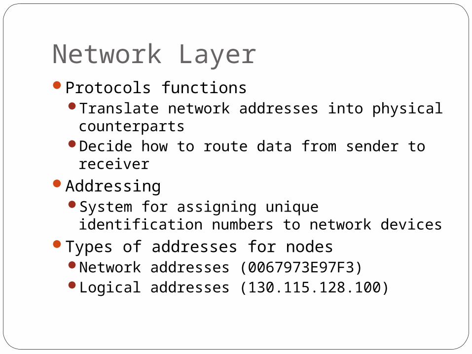
Protocols functionsTranslate network addresses into physical
counterpartsDecide how to route data from sender to
receiverAddressing
System for assigning unique identification numbers to network devices
Types of addresses for nodesNetwork addresses (0067973E97F3)Logical addresses (130.115.128.100)

Network Layer (cont’d.)
26
Packet formation is hereTransport layer segment appended with logical
addressing informationRouting
Determine path from point A on one network to point B on another network
Routing considerationsDelivery priorities, network congestion, quality of
service, cost of alternative routesFragmentation
Network layer protocol (IP) subdivides Transport layer segments received into smaller packets
Data Link Layer
27
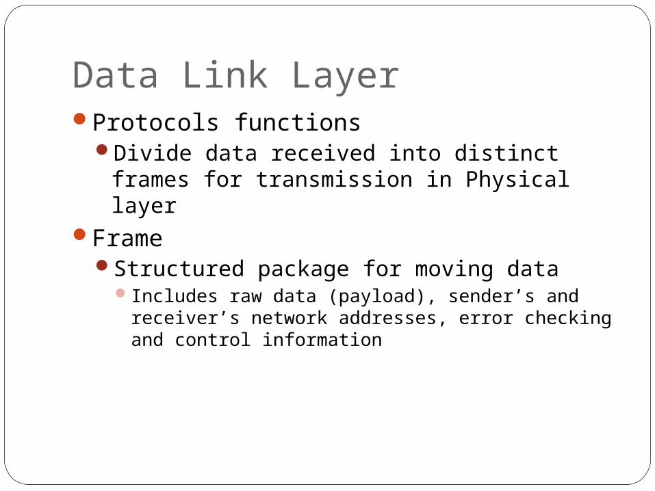
Protocols functionsDivide data received into distinct frames for
transmission in Physical layerFrame
Structured package for moving dataIncludes raw data (payload), sender’s and receiver’s
network addresses, error checking and control information

Data Link Layer (cont’d.)
28
Possible partial communication mistake Not all information received or correctly
Frames are not the sameCorrected by error checking
Possible glut of communication requestsData Link layer controls flow of information
Allows NIC to process data without error
Data Link Layer (cont’d.)
29
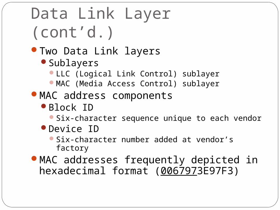
Two Data Link layersSublayers
LLC (Logical Link Control) sublayerMAC (Media Access Control) sublayer
MAC address componentsBlock ID
Six-character sequence unique to each vendorDevice ID
Six-character number added at vendor’s factoryMAC addresses frequently depicted in
hexadecimal format (0067973E97F3)

Data Link Layer (cont’d.)
30
Figure 2-5 The Data Link layer and its sublayers
Physical Layer
31
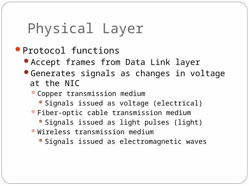
Protocol functionsAccept frames from Data Link layerGenerates signals as changes in voltage at the
NICCopper transmission medium
Signals issued as voltage (electrical)Fiber-optic cable transmission medium
Signals issued as light pulses (light)Wireless transmission medium
Signals issued as electromagnetic waves

Physical Layer (cont’d.)
32
Physical layer protocols responsibility when receiving dataDetect and accept signalsPass on to Data Link layerSet data transmission rateMonitor data error ratesNo error checking

Applying the OSI Model
33
Table 2-1 Functions of the OSI layers
Communication Between Two Systems
34
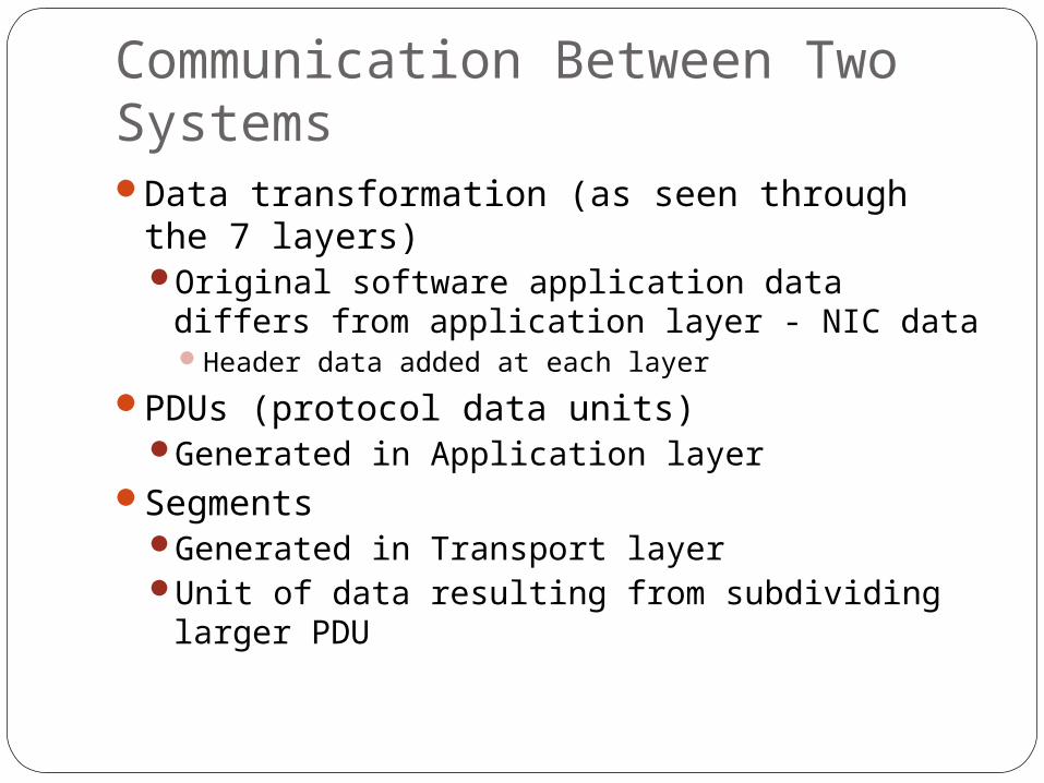
Data transformation (as seen through the 7 layers)Original software application data differs
from application layer - NIC dataHeader data added at each layer
PDUs (protocol data units)Generated in Application layer
SegmentsGenerated in Transport layerUnit of data resulting from subdividing larger
PDU

Communication Between Two Systems (cont’d.)
35
PacketsGenerated in Network layerData with logical addressing information
added to segmentsFrames
Generated in Data Link layerComposed of several smaller components or
fields

Communication Between Two Systems (cont’d.)
36
EncapsulationOccurs in Data Link layerProcess of wrapping one layer’s PDU with
protocol informationAllows interpretation by lower layer

Communication Between Two Systems (cont’d.)
37
Figure 2-7 Data transformation through the OSI model
Frame Specifications
38
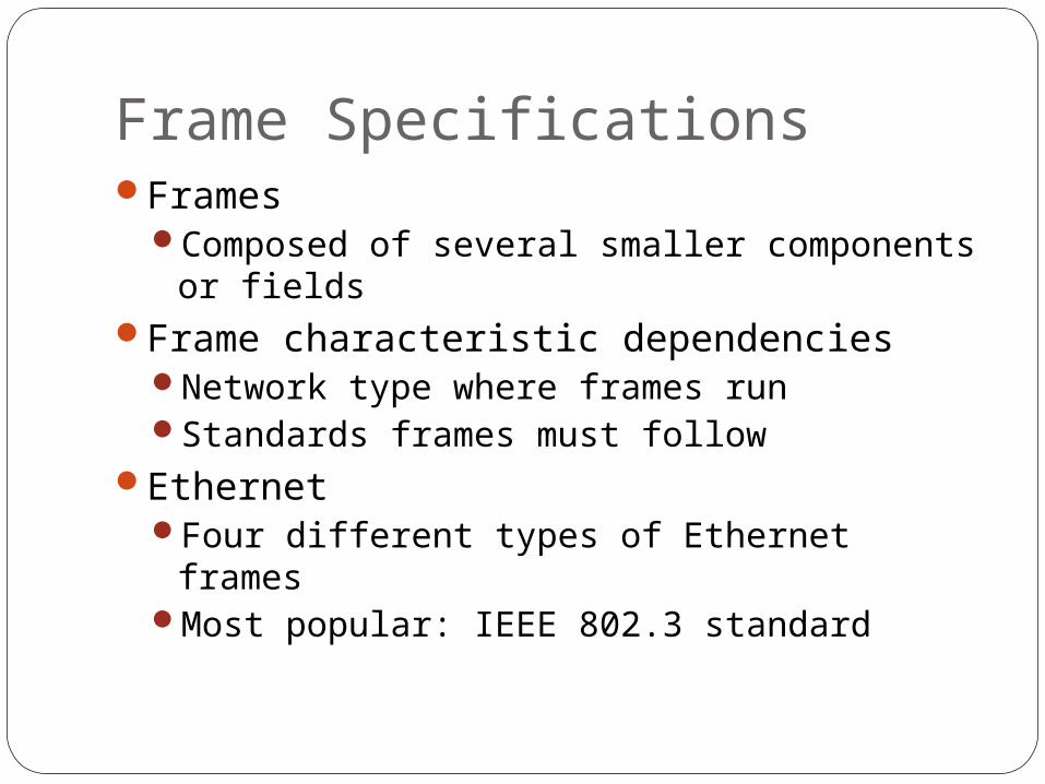
FramesComposed of several smaller components or
fieldsFrame characteristic dependencies
Network type where frames runStandards frames must follow
EthernetFour different types of Ethernet framesMost popular: IEEE 802.3 standard
Frame Specifications (cont’d.)
39
Token ringEthernet frames and token ring frames
differWill not interact with each otherDevices cannot support more than one frame
type per physical interface or NIC

IEEE Networking Specifications
40
IEEE’s Project 802Effort to standardize physical and logical
network elements Frame types and addressingConnectivityNetworking mediaError-checking algorithmsEncryptionEmerging technologies
802.3: Ethernet802.11: Wireless

IEEE Networking Specifications (cont’d.)
41Table 2-2 IEEE 802 standards
Summary
42
Standards and standard organizationsISO’s OSI (Open Systems Interconnection)
modelSeven layers
IEEE’s Project 802Significant IEEE 802 standards

43
Thanks