Embed Size (px)
Citation preview

BRKRST-2069
Network Virtualisation Design Concepts LAN and WAN (VRF, MPLS, EVN)
www.ciscolivevirtual.com

© 2012 Cisco and/or its affiliates. All rights reserved. Cisco Public BRKRST-2069 2 2
Participants should have:
A solid base knowledge of IP routing, IP tunnels, and Campus and WAN design fundamentals and technologies
Basic knowledge of VRF’s, GRE tunnels, and DMVPN
Basic understanding of MP-BGP, MPLS control/forwarding plane
This discussion will not cover VMware, Virtual Machines, or other server virtualization technologies
Understanding Data Center Interconnection (DCI) is an important application that leverages WAN virtualization infrastructure, it is not a focus in this session nor is Layer 2 Virtualization technologies
RFC 2547 (BGP/MPLS IP VPNs) is referenced frequently for MPLS VPN. This is for familiarity only. RFC 2547 is now replaced with RFC 4364.
Assumptions/Disclaimers Craig Hill

© 2012 Cisco and/or its affiliates. All rights reserved. Cisco Public BRKRST-2069 4 4
Agenda
Network Virtualization Drivers and Building Blocks
Enterprise Campus and WAN Deployment Considerations and Variations
Deployment Solutions for a Virtualized Campus and WAN
QoS Deployment Considerations in a Virtualized Campus and WAN
Recent Innovations at Cisco in Virtualization
Summary

© 2012 Cisco and/or its affiliates. All rights reserved. Cisco Public BRKRST-2069 5 5
Agenda
Network Virtualization Drivers and Building Blocks
Enterprise Campus and WAN Deployment Considerations and Variations
Deployment Solutions for a Virtualized Campus and WAN
QoS Deployment Considerations in a Virtualized Campus and WAN
Recent Innovations at Cisco in Virtualization
Summary

© 2012 Cisco and/or its affiliates. All rights reserved. Cisco Public BRKRST-2069 6 6
Evolution of “Network” Virtualization …Means Many Things to Many People
It has evolved a long way from technologies like TDM (1960’s)
From TDM, ATM/FR Virtual Circuits in the WAN, to…
VLANs in the Campus, to…
Logical/Virtual Routers on routing devices, to…
Virtual Machines on server clusters in the data center
Time
TDM
HSRP MPLS VPN
MPLS
VLANs
VRF Lite
Virtual Circuits
2012+
GRE
Secure Domain
Routers
Virtual
Machines
(VMware)
Virtual
Device
Context
Virtual
Port
Channel
L2TPv3
AToM VPLS
Virtual Sw
System VN Link
© 2012 Cisco and/or its affiliates. All rights reserved. Cisco Public BRKRST-2069 7 7
Virtual Network
Merged Company
What Is “Network” Virtualization? Giving One physical network the ability to support multiple virtual networks
End-user perspective is that of being connected to a dedicated network (security, independent set of policies, routing decisions…)
Maintains Hierarchy, Virtualizes devices, data paths, and services
Allows for better utilization of network resources
Actual Physical Infrastructure
Virtual Network Virtual Network
Guest Access Network Internal Organizational Separation (Eng, Sales)
© 2012 Cisco and/or its affiliates. All rights reserved. Cisco Public BRKRST-2069 8 8
Why Network Virtualization? Key Drivers
Cost Reduction—allowing a single physical network the ability to support multiple users and virtual networks
Simpler OAM—reducing the amount of network devices needing to be managed and monitored
Security—maintaining segmentation of the network for different departments over a single device/Campus/WAN
High Availability—leverage virtualization through clustering devices that appear as one (vastly increased uptime)
Data Center Applications—require maintained separation, end-to-end (i.e. continuity of virtualization from server-to-campus-to-WAN) , including Multi-tenant DC’s for Cloud Computing
Common Use Cases Guest Access, Airports, Cloud Computing IaaS, Physical Security Separation, Company Mergers Regulation/Compliance – Health Care (HIPPA), Credit Card (PCI)

© 2012 Cisco and/or its affiliates. All rights reserved. Cisco Public BRKRST-2069 10
SiSi
Enterprise Network Virtualization Key Building Blocks
Device Partitioning
Virtualized Interconnect
Device Pooling
SiSi SiSi
“Virtualizing” the
Routing and
Forwarding of the
Device
“Virtualizing”
Multiple Devices
to Function as a
Single Device
Extending and
Maintaining the
“Virtualized”
Devices/Pools over Any
Media

© 2012 Cisco and/or its affiliates. All rights reserved. Cisco Public BRKRST-2069 11
SiSi
Enterprise Network Virtualization The Building Blocks – Example Technologies
Device Partitioning
VDC (NX-OS)
(Virtual Device Context)
SDR (IOS-XR)
(Secure Domain Routers)
FW Contexts
VLANs
VRFs
EVN
(Easy Virtual Network)
Virtualized Interconnect
L3 VPNs – MPLS VPNs, GRE, VRF-Lite, MPLS services (L2/L3) over GRE
L2 VPNs - AToM, Unified I/O, VLAN trunks
Evolving – TRILL, 802.1ah, 802.1af
Device Pooling
VSS
Stackwise
Virtual Port Channel (vPC)
HSRP/GLBP
SiSi SiSi

© 2012 Cisco and/or its affiliates. All rights reserved. Cisco Public BRKRST-2069 13
SiSi
Enterprise Network Virtualization The Building Blocks – Example Technologies
Device Partitioning
VDCs
SDR (XR)
FW Contexts
VLANs
VRFs
Virtualized Interconnect
L3 VPNs – MPLS VPNs, GRE, VRF-Lite, MPLS services (L2/L3) over GRE
L2 VPNs - AToM, Unified I/O, VLAN trunks
Evolving – TRILL, 802.1ah, 802.1af
Device Pooling
Virtual Sw System (VSS)
Virtual Port Channel (vPC)
HSRP/GLBP
Stackwise
SiSi SiSi
© 2012 Cisco and/or its affiliates. All rights reserved. Cisco Public BRKRST-2069 14
MPLS-TP = MPLS Transport Profile
Enterprise Network Virtualization The Building Blocks – Example Technologies
Device Partitioning
Virtualized Interconnect
L3 VPNs – MPLS VPNs, VRF-Lite, MPLS VPN or VRF-Lite
over IP
L2 VPNs – PWE3, VPLS, L2 VPN over IP, L2TPv3, OTV
(Overlay Transport Virtualization)
Evolving Standards – Fat-PW, MPLS-TP, Ethernet-VPN, LISP
Virtualization
Device Pooling
VSS
Stackwise
Virtual Port Channel (vPC)
HSRP/GLBP
SiSi SiSi
WAN
Campus
VDC (NX-OS)
(Virtual Device Context)
SDR (IOS-XR)
(Secure Domain Routers)
FW Contexts
VLANs
VRFs
EVN
(Easy Virtual Network)

© 2012 Cisco and/or its affiliates. All rights reserved. Cisco Public BRKRST-2069 16 16
Agenda
Network Virtualization Drivers and Building Blocks
Enterprise Campus and WAN Deployment Considerations and Variations
Deployment Solutions for a Virtualized Campus and WAN
QoS Deployment Considerations in a Virtualized Campus and WAN
Recent Innovations at Cisco in Virtualization
Summary

© 2012 Cisco and/or its affiliates. All rights reserved. Cisco Public BRKRST-2069 17
Differences Applying Virtualization to Campus and WAN
© 2012 Cisco and/or its affiliates. All rights reserved. Cisco Public BRKRST-2069 18
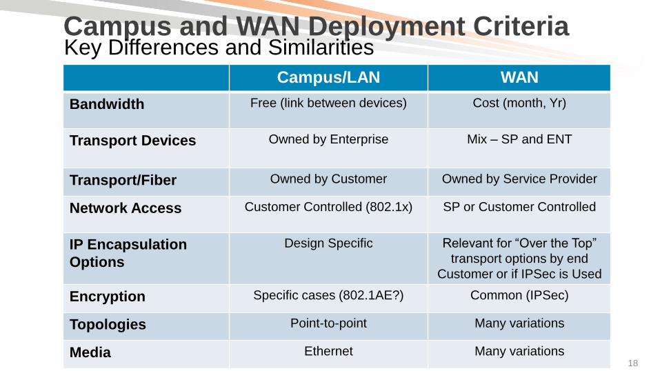
Campus and WAN Deployment Criteria
Campus/LAN WAN
Bandwidth Free (link between devices) Cost (month, Yr)
Transport Devices Owned by Enterprise Mix – SP and ENT
Transport/Fiber Owned by Customer Owned by Service Provider
Network Access Customer Controlled (802.1x) SP or Customer Controlled
IP Encapsulation
Options
Design Specific Relevant for “Over the Top”
transport options by end
Customer or if IPSec is Used
Encryption Specific cases (802.1AE?) Common (IPSec)
Topologies Point-to-point Many variations
Media Ethernet Many variations
Key Differences and Similarities

© 2012 Cisco and/or its affiliates. All rights reserved. Cisco Public BRKRST-2069 20
What is Unique in the WAN for Virtualization?

© 2012 Cisco and/or its affiliates. All rights reserved. Cisco Public BRKRST-2069 21 21
Today’s WAN Transport Options
Topologies
Point-point, multi-point
Full/partial mesh
Hub/Spoke or Multi-Tier
Media
Serial, ATM/FR, OC-x
Dark fiber, Lambda
Ethernet
VPN Transport Services
L2 - Metro-E (p2p, p2mp)
L3 – Private IP VPN
L3 – Public (Internet)
Overlay Options
GRE
Dynamic Multipoint VPN (DMVPN)
L2/L3 VPN over IP
WAN
LAN LAN

© 2012 Cisco and/or its affiliates. All rights reserved. Cisco Public BRKRST-2069 23
Self Deployed MPLS vs. SP L3 Managed Network Virtualization Deployment Options
Customer manages and owns:
IP routing, provisioning
Transport for PE-P, P-P, PE-CE
SLA’s, to “end” customer
QoS, Traffic Engineering
Allows customer full control E2E
CE Routers owned by customer
PE Routers owned by SP
Customer “peers” to “PE” via IP
Exchanges routing with SP via routing protocol (or static route)
Customer relies on SP to advertise routes to reach other customer CEs
Self Deployed MPLS
Customer Deployed
MPLS Backbone
Site 2
Site3
Site1
PE PE
CE
CE
CE P P
P
Customer Managed
Self Deployed MPLS
Backbone
Provider
MPLS
VPN Site 2
Site3
Site1
IP Routing Peer
(BGP, Static, IGP)
PE PE
SP Demarcation
CE
CE
CE
Customer
Managed
Customer
Managed
SP Managed IP VPN Service
* No Labels Are Exchanged with the SP

© 2012 Cisco and/or its affiliates. All rights reserved. Cisco Public BRKRST-2069 24
Self Deployed MPLS “over” SP L3 Managed Service Creates a “Carrier over Carrier” Model
CE Routers owned by customer
PE Routers owned by SP
Customer “peers” to “PE” via IP
Exchanges routing with SP
Add overlay of IP that allows self-deployed MPLS over an IP Service
Provider
MPLS
VPN
Site 2
Site3
Site1
IP Routing to SP
PE PE
SP Managed IP VPN Service
SP Demarc
CE
CE
CE
Customer
Managed
Customer
Managed
X over GRE
VRF’s
Provider
MPLS
VPN
Site 2
Site3
Site1
PE PE
L3 VPN over IP WAN Service
C-PE
C-PE
C-PE
Customer Managed VRF/MPLS over IP
Customer MPLS VPN
CE routers become MPLS PE (c-PE)
VRFs or MPLS labels are encapsulated in IP
Other options not as scalable or more complex:
Carrier Supporting Carrier
Back to Back VRFs/Inter-AS Option “A”
Layer 2 Service (e.g. VPLS)
X over GRE IP Routing to SP
VRF’s
SP Demarc

What is Unique in the LAN for Virtualization?

© 2012 Cisco and/or its affiliates. All rights reserved. Cisco Public BRKRST-2069 26
Campus Network Design Best Practices
Data Center WAN Internet
Layer 3
Equal Cost
Links
Layer 3
Equal Cost
Links
Access
Distribution
Core
Distribution
Access
SiSi SiSi SiSi SiSi SiSi SiSi
SiSi SiSi
SiSi SiSi
SiSi SiSi
SiSi SiSi
Hierarchical Net - Offers hierarchy—each
layer has specific role
Modular topology— building blocks
Easy to grow, understand, and troubleshoot
Creates small fault domains— Clear
demarcations and isolation
Promotes load balancing and redundancy
Promotes deterministic traffic patterns
Incorporates balance of both Layer 2 and
Layer 3 technology, leveraging the strength
of both
Utilizes Layer 3 routing for load balancing,
fast
VRF/VLAN

© 2012 Cisco and/or its affiliates. All rights reserved. Cisco Public BRKRST-2069 27 27
Access Control – Campus “On Ramp” Authentication, Authorization
Authentication—Who/what is requesting access?
Holistic control—Client-based, infrastructure integrated— 802.1X
User-based control—Clientless—Web authentication, Webauth
Device-specific control—MAC-address based
Machine Auth, AAA Override, SSID (guest)
Authorization—Where/how is the access granted?
Allow access to the network to a particular VLAN or VRF Edge Access Control
Resources
Dept A Partner Guest
Internet
Dept B

© 2012 Cisco and/or its affiliates. All rights reserved. Cisco Public BRKRST-2069 28 28
Services Edge Sharing Services Between VPNs
Services usually not duplicated per group
Economical
Efficient and manageable
Policies centrally deployed
Blue VPN
Green VPN
Red VPN
Resources
Campus Core
Red User
Shared Resource
Green User Blue User
Internet/Shared
Internet Gateway
IPSec Gateway
DHCP
Video Server
Firewall and NAT
Hosted Content
Shared for All Groups:

© 2012 Cisco and/or its affiliates. All rights reserved. Cisco Public BRKRST-2069 31
Enterprise Virtualization End to End WAN Virtualization
Distribution Blocks
SiSiSiSiSiSiSiSi
SiSi
SiSi SiSi
SiSi
Internet
Campus
Yellow VRF
Green VRF
Red VRF
Branch 1
Yellow VRF
Green VRF
Red VRF
Branch 2
Yellow VRF
Green VRF
Red VRF
Branch 3
Data Center 1 WAN
• Allow Virtualization over the WAN via
any transport/media
• support QoS and multicast
• Offer variations of complexity and scale
• Leverage industry standards

© 2012 Cisco and/or its affiliates. All rights reserved. Cisco Public BRKRST-2069 32 32
Agenda
Network Virtualization Drivers and Building Blocks
Enterprise Campus and WAN Deployment Considerations and Variations
Deployment Solutions for a Virtualized Campus and WAN
QoS Deployment Considerations in a Virtualized Campus and WAN
Recent Innovations at Cisco in Virtualization
Summary

Layer 3 Network Virtualization Technology Overview

VRF-Lite

© 2012 Cisco and/or its affiliates. All rights reserved. Cisco Public BRKRST-2069 35
WAN/Campus
What Is VRF Lite?
VRF VRF VRF
VRF VRF VRF
Defines router supports routing (RIB), forwarding (FIB), and interface per VRF !!
Leverages “Virtual” encapsulation for separation:
ATM VCs, Frame Relay, Ethernet/802.1Q
The routing protocol is also “VRF aware”
EIGRP, OSPF, BGP, RIP/v2, static (per VFR)
Layer 3 VRF interfaces cannot belong to more than a single VRF
802.1q, DLCI, VPI/VCI, GRE
WAN Campus
Per VRF: Virtual Routing Table Virtual Forwarding Table

© 2012 Cisco and/or its affiliates. All rights reserved. Cisco Public BRKRST-2069 36 36
IGP/DLCI per VRF
WAN
Transport Branch Site
Multi-
VRF CE
Enterprise Routing
VRF-Lite over Layer 2 Transport Extend Virtualization over WAN L2 Service
Each Frame Relay VC contains a sub-interface
Unique DLCI per VRF
Routing protocol process created per VRF in both Branch/Campus
Offers virtualized segmentation within a single interface
Same applies to 802.1Q (if Ethernet Services was utilized)
FR Sub-
Interfaces Data Center/HQ
PE
Shared
VRF
Internet Campus
VRF-Lite or
VPNv4 to
Campus
VRF-Lite or MPLS
VPN in PE Frame
Relay FR VC’s
IGP/DLCI per VRF
IGP/DLCI per VRF

© 2012 Cisco and/or its affiliates. All rights reserved. Cisco Public BRKRST-2069 38
VRF-Lite End-to-End Target Requirements in the Campus
VLAN 10 VLAN 20
IGPs
End to End segmentation, per VRF and per inteface
Targets a small number of VRFs are required
Usually deployed in campus networks requiring a where the hop count is smaller as well (~1-2)
Seen frequently in Access Distribution (vs. end to end)
No MP-BGP or control plane signaling is required and does not use labels
No LDP is required (i.e. MPLS)
Still leverages existing QoS model and supports IP multicast
Full range of platform support within the Cisco portfolio of switches and routers
VLAN 16 VLAN 26
VLAN 12 VLAN 22
VLAN 13 VLAN 23
VLAN 15 VLAN 25
VLAN 11 VLAN 21
VLAN 14 VLAN 24

© 2012 Cisco and/or its affiliates. All rights reserved. Cisco Public BRKRST-2069 39
VRF-Lite in the Campus and WAN Summary
Leverages VRF in router (RIB/FIB, interface) and interface for
segmentation
No MPLS, LDP, or BGP required
Optimal solution when VRF count is small (~ <8)
Scale usually dependent on routing protocol
Supports multicast and QoS solutions
Most common deployments?
Campus – Small # of VRFs, AccessDistribution, DistCore
WAN - Branch Back-haul to campus, Branch Back-haul to aggregation PE running full
MPLS VPN Sub Interface per
VRF

Multi-Protocol Label Switching (MPLS) over L2 Encapsulation in the WAN

© 2012 Cisco and/or its affiliates. All rights reserved. Cisco Public BRKRST-2069 41 41
MPLS: Robust “WAN/Campus” Virtualization Enabler Allows Vast Network “Service” Capabilities over an IP Backbone
Layer 3 VPN/Segmentation
VPN (RFC 2547bis)
Provides Any-to-Any connectivity
Maximize Link Utilization with Selective Routing/Path Manipulation
Traffic Engineering
Optimization of bandwidth and protection using Fast-ReRoute (FRR)
Layer 2 VPN/Transport
AToM (Any Transport over MPLS) i.e. “pseudo-wire”
Layer-2 transport: Ethernet, ATM/FR, HDLC/PPP, interworking
Layer-2 VPN: VPLS for bridged L2 domains over MPLS
QoS Capabilities
Diffserv, Diffserv aware Traffic Engineering (DS-TE)
Bandwidth Protection Services
Combination of TE, Diffserv, DS-TE, and FRR
IP Multicast (per VPN/VRF)
Transport of IPv6 over an IPv4 (Global Routing Table) Infrastructure
Unified Control Plane (Generalized MPLS)
Key Virtualization
Mechanisms over
an IP Infrastructure

© 2012 Cisco and/or its affiliates. All rights reserved. Cisco Public BRKRST-2069 42
MPLS Label Encapsulations Applicable When Using MPLS over Layer 2 Transport
Label PPP Header Layer 2/L3 Packet PPP Header
(Packet over SONET/SDH)
Label MAC Header Layer 2/L3 Packet LAN MAC Label Header
One or More Labels Appended to the Packet
MAC Header Label 1 Label 2 IP Header Label Stacking
(LAN Example) Outer Label
(Used for Forwarding)
Inner Label
L3 VPN
L2 VPN

© 2012 Cisco and/or its affiliates. All rights reserved. Cisco Public BRKRST-2069 43
MPLS VPN Technology—Refresher MPLS VPN Connection Model
PE Routers
MPLS Edge routers
MPLS forwarding to P routers
IGP/BGP – IP to CE routers
Distributes VPN information through MP-BGP to other PE routers with VPN-IPv4 addresses, extended community, VPN labels
P Routers
P routers are in the core of the MPLS cloud
P routers do not need to run BGP
Do not have knowledge of VPNs
Switches packets based on labels (push/pop) not IP
PE
VPN Backbone IGP
MP-iBGP – VPNv4 Label Exchange
PE
P P
P P
VRF Blue
VRF Green
EBGP, OSPF, RIPv2, Static
CE
CE
VPN 1
VPN 2
CE Routers
VRF Associates to one or more interfaces on PE
Has its own routing table and forwarding table (CEF)
VRF has its own instance for the routing protocol
(static, RIP, BGP, EIGRP, OSPF)
Global Address Space
WAN Campus

© 2012 Cisco and/or its affiliates. All rights reserved. Cisco Public BRKRST-2069 47
PE VPN Backbone IGP
MP-iBGP – VPNv4
Label Exchange
PE
P P
P P
MPLS VPN over L2 Configuration Example (IOS)
VRF Blue
VRF Green
EBGP, OSPF, RIPv2, Static
CE
CE VPN 1
VPN 2
! PE router
router bgp 65100
neighbor 192.168.100.4 remote-as 65100
!
address-family vpnv4
neighbor 192.168.100.4 activate
neighbor 192.168.100.4 send-community extended
exit-address-family
!
address-family ipv4 vrf blue
neighbor 172.20.10.1 remote-as 65111
neighbor 172.20.10.1 activate
exit-address-family
! PE Router – Multiple VRFs
ip vrf blue
rd 65100:10
route-target import 65100:10
route-target export 65100:10
ip vrf green
rd 65100:20
route-target import 65100:20
route-target export 65100:20
!
interface GigabitEthernet0/1.10
ip vrf forwarding blue
interface GigabitEthernet0/1.20
ip vrf forwarding green
VRF Configuration (PE) MP-iBGP Configuration (PE)

© 2012 Cisco and/or its affiliates. All rights reserved. Cisco Public BRKRST-2069 48
Internet Data Center
WAN
P P
PE PE PE PE PE PE
PE PE PE PE PE PE
MPLS-VPNs in the Campus Architecture General Design Considerations
Highly scalable
Usually deployed in large campus networks requiring a large number of VRFs
Any to any connectivity per user group
User to cloud connectivity
VPN traffic is ‘tunneled’ across the MPLS core
Access Layer Options
1 - L2 – VLAN extension to PE
2 - L3 – VRF Lite from Access to Distribution
3 - L3 – MPLS on the Access switch (6500 only today)
Campus platform support for MPLS VPN currently targets Catalyst 6500 Series and Nexus 7000
Support for Cisco Catalyst 6500 Series running MPLS in VSS mode available from 12.2(33)SXI2 release
MPLS
Core

© 2012 Cisco and/or its affiliates. All rights reserved. Cisco Public BRKRST-2069 49 49
MPLS VPN over L2 – WAN and Campus Summary and Deployment Targets
Targets large-scale VRF’s and customers wanting control!
Leverages standard based L2 transports (no overlay) in the WAN (Campus still
Ethernet)
Target customers usually function as an “internal Service Provider” for their
company/agency
Allows full deployment of MPLS services
L2 VPN, QoS, Multicast, IPv6, MPLS TE, TE-FRR
Offers tight control for QoS Service Level requirements
Offers rapid deployment for virtualization “turn up”
Extremely scalable but requires a higher level of Operational expertise

L3 Virtualization over IP

© 2012 Cisco and/or its affiliates. All rights reserved. Cisco Public BRKRST-2069 51 51
Why Do We Need IP Virtualization over IP? VRF-Lite Requires Layer 2 for Separation
Need to leverage IP for broader reach, and more transport options
Not all networks are MPLS
MPLS is not available for transport on every network
Enterprise wants to turn on their own MPLS VPN service (on their “CE”) while using an SP managed MPLS VPN service
IP Only Transit Option Between MPLS Islands (i.e. networks)
Core/transit network not owned by Enterprise, and IP transport is only option
Source/Destination Network “islands” are IP only
IP VPN Service from SP is only offering available (vs. L2 option)
Customer uses “external” IP encryption units (i.e. device does not support MPLS)
Extend MPLS Services over any IP Transport
Designer can utilize any “IP” transport that exists
Leverage internet “reach” for access outside controlled area
In Summary, the Implementation Strategy Described Enables the Deployment of BGP/MPLS IP VPN Technology
in Networks Whose Edge Devices are MPLS and VPN Aware, But Whose Interior Devices Are Not
(Source: RFC 4797)
VRF-Lite over IP

© 2012 Cisco and/or its affiliates. All rights reserved. Cisco Public BRKRST-2069 53
GRE Tunnel Encapsulation (RFC 2784) Applicable over Any IP WAN Transport
Original IP Header IP Payload GRE Header New IP Header
20 Bytes 20 Bytes 4 Bytes
GRE Packet with New IP Header:
Protocol 47 (Forwarded Using New IP Dst)
Original IP Header IP Payload
20 Bytes
Original IP Datagram (Before Forwarding)
Bit 0: Check Sum
Bit 1-12: Reserved
Bit 13-15: Version Number
Bit 16-31: Protocol Type
IP WAN
Router A Router B
GRE Tunnel
Can Also Leverage IPSec When IP Encryption Is Required of an Untrusted WAN

© 2012 Cisco and/or its affiliates. All rights reserved. Cisco Public BRKRST-2069 54
IP Transport
VRF-Lite over IP Transport VRF-Lite over GRE
VRF
VRF
VRF
Per VRF: Virtual Routing Table Virtual Forwarding Table
VRF
VRF
VRF
VRF Lite can also leverage GRE tunnels as a segmentation
technology
Each VRF uses a unique GRE tunnel
GRE tunnel interface is “VRF aware”
GRE Tunnel
GRE Tunnel
GRE Tunnel
Campus/WAN
WAN Campus

© 2012 Cisco and/or its affiliates. All rights reserved. Cisco Public BRKRST-2069 55 55
IGP per VRF
IGP per VRF
IPv4
Service
Branch Site Multi-
VRF CE
IGP per VRF
BGP/Static BGP/Static
Enterprise Routing
Routing to SP
VRF-Lite over the WAN VRF-Lite per GRE Tunnels
Each GRE tunnel contains a VRF for extension
Routing protocol process created per VRF (each end)
Common Deployment: BranchAggregation Backhaul, low number of VRF’s are required
mGRE Tunnel
per VRF Data Center/HQ
PE
Shared
VRF
Internet Campus
VRF-Lite or
VPNv4 to
Campus
VRF-Lite or MPLS
VPN in PE
Configuration Note: Each GRE Tunnel Could Require Unique Source/Dest IP (Platform Dependent)
WAN Campus

© 2012 Cisco and/or its affiliates. All rights reserved. Cisco Public BRKRST-2069 56 56
IP
Transport
Branch Site
VRF-Lite over Point-to-Point GRE Example for “Blue” VRF (IOS)
VRF-Lite or
VPNv4 to
Campus
Data Center/HQ
PE
Shared
VRF
Internet
VRF-Lite or MPLS
VPN in PE
Campus
DC/HQ Configuration Branch Configuration interface Loopback100
ip address 172.16.100.50 255.255.255.255
!
interface Tunnel100
Description GRE to PE router 201
ip vrf forwarding blue
ip address 11.1.0.2 255.255.255.0
tunnel source Loopback100
tunnel destination 172.16.100.10
!
interface Ethernet0/0
ip address 172.16.5.2 255.255.255.0
!
router eigrp 1
!
address-family ipv4 vrf blue autonomous-system 1
network 11.0.0.0
no auto-summary
exit-address-family
no auto-summary
interface Loopback100
ip address 172.16.100.10 255.255.255.255
!
interface Tunnel100
Description GRE to PE router 201
ip vrf forwarding blue
ip address 11.1.0.1 255.255.255.0
tunnel source Loopback100
tunnel destination 172.16.100.50
!
interface Ethernet0/0
ip address 172.16.6.2 255.255.255.0
!
router eigrp 1
!
address-family ipv4 vrf blue autonomous-system 1
network 11.0.0.0
no auto-summary
exit-address-family
no auto-summary
11.1.0.x
Physical: 172.16.5.2 (E0/0)
Lo0: 172.16.100.50
Manually Configured Tunnel ip vrf blue
rd 2:2
VRF Command
Applied per
GRE Tunnel
Prefix Advertised to SP
WAN Campus

© 2012 Cisco and/or its affiliates. All rights reserved. Cisco Public BRKRST-2069 58
Internet Data Center
WAN
P P
PE PE PE PE PE PE
PE PE PE PE PE PE
VRF-Lite over GRE Tunnels in the Campus General Design Considerations
IP
Backbone
Deployment
Recommended for hub-and-spoke “one off” requirements
Limited scale for single or few VPN applications (guest access, NAC remediation)
GRE supported in HW on Catalyst 6500, Nexus 7000
Application and Services
Multiple VRF-aware Services available
Learning Curve
Familiar routing protocols can be used
IP Based transport solution
VRF over GRE

MPLS VPN over IP

© 2012 Cisco and/or its affiliates. All rights reserved. Cisco Public BRKRST-2069 60
GRE (RFC 2784) with GRE+MPLS (RFC 4023) Packet Format
Original IP Header IP Payload GRE Header New IP Header
20 Bytes 20 Bytes 4 Bytes
GRE pPacket with New IP Header:
Protocol 47 (Forwarded Using New IP Dst)
Original IP Header IP Payload
20 Bytes
Original IP Datagram (Before Forwarding)
Bit 0: Check Sum
Bit 1-12: Reserved
Bit 13-15: Version Number
Bit 16-31: Protocol Type
Protocol Type (MPLS over GRE)
Unicast: 0x8847
Multicast: 0x8848
Protocol Version Number: 137
Indicates an MPLS Unicast Packet

© 2012 Cisco and/or its affiliates. All rights reserved. Cisco Public BRKRST-2069 61
New IP Header GRE Header
IP Payload
GRE Tunnel Format with MPLS (Reference: RFC 4023)
20 Bytes
Original IP Header
Original MPLS/IP Datagram (Before Forwarding)
Ethertype in the Protocol
Type Field Will Indicate
an MPLS Label Follows
VPN Label Fwding Label L2 Header
IP Payload Original IP Header
20 Bytes 4 Bytes
VPN Label L2 Header
MPLS Tunnel label (top) is replaced with destination PE’s IP address
Encapsulation defined in RFC 4023
Most widely deployed form of MPLS over IP encapsulation
VPN Label Is Signaled via MP-
BGP . This Is Normal MPLS VPN
Control Plane Operation.
MPLS/IP Datagram over GRE (After Forwarding)

Virtualization over Multipoint GRE (mGRE) Tunnels

© 2012 Cisco and/or its affiliates. All rights reserved. Cisco Public BRKRST-2069 63 63
GRE Tunnel Modes “Stateful” vs. “Stateless”
Source and destination requires manual
configuration
Tunnel end-points are stateful neighbors
Tunnel destination is explicitly configured
Creates a logical point-to-point “Tunnel”
Remote Site
Central
Site
Point-to-Point GRE
IP Network Central
Site
Multipoint GRE
Remote Sites
Single multipoint tunnel interface is created per
node
Only the tunnel source is defined
Tunnel destination is derived dynamically through
some control plane mechanism (i.e. BGP, NHRP)
or discovery end-point concept
Creates an “encapsulation” using IP headers
(GRE)
IP Network IP Tunnel

© 2012 Cisco and/or its affiliates. All rights reserved. Cisco Public BRKRST-2069 65
Dynamic Multipoint VPN
Provides full meshed connectivity with simple configuration of hub and spoke
Supports dynamically addressed spokes
Facilitates zero-touch configuration for addition of new spokes
Features automatic IPsec triggering for building an IPsec tunnel
Spoke n
Traditional Static Tunnels
DMVPN Tunnels
Static Known IP Addresses
Dynamic Unknown IP Addresses
Hub
VPN Spoke 1
Spoke 2
Secure On-Demand Meshed Tunnels
WAN

© 2012 Cisco and/or its affiliates. All rights reserved. Cisco Public BRKRST-2069 66
Data Center/HQ
VRF-Lite over Dynamic Multipoint VPN (DMVPN)
L3 Virtualization Extension over DMVPN
Allows virtualization over DMVPN
framework
A Multipoint GRE (mGRE) interface is
enabled per VRF (1:1)
Solution allows spoke-to-spoke data
forwarding per VRF
Deployment Target: Customers
already running DMVPN, but needs to
add VRF capabilities to sites
VRF-Lite or
MPLS
VPN in Campus
PE
Remote
Branches
Multi-
VRF CE
Multipoint
GRE Tunnel
per VRF
IP
Transport
Branch LAN
Shared
VRF
Campus
C-PE C-PE
C-PE
Internet
mGRE Tunnel per
VRF
WAN

© 2012 Cisco and/or its affiliates. All rights reserved. Cisco Public BRKRST-2069 68 68
IP
Transport
Branch Site Multi-
VRF CE
VRF-Lite over DMVPN Example (IOS)
Per-VRF
NHRP
Server
mGRE Tunnel
per VRF Data Center/HQ
PE
Shared
VRF
Internet
VRF-Lite or MPLS
VPN in Campus
Campus
Hub Configuration
ip vrf blue
!
interface Loopback0
ip address 10.126.100.1 255.255.255.255
!
interface Tunnel0
description mGRE for blue
ip vrf forwarding blue
ip address 11.1.1.1 255.255.255.0
no ip redirects
ip nhrp map multicast dynamic
ip nhrp network-id 100
tunnel source Loopback0
tunnel mode gre multipoint
ip vrf blue
!
interface Loopback0
ip add 10.123.100.1 255.255.255.255
!
interface Tunnel0
description GRE to hub
ip vrf forwarding blue
ip address 11.1.1.10 255.255.255.0
ip nhrp network-id 100
ip nhrp nhs 11.1.1.1
tunnel source Loopback0
tunnel destination 10.126.100.1
!
interface Vlan10
description blue Subnet
ip vrf forwarding blue
ip address 11.1.100.1 255.255.255.0
Spoke Configuration
Unique “network-id” Parameter per VRF
Branch Site mGRE Tunnel
per VRF

© 2012 Cisco and/or its affiliates. All rights reserved. Cisco Public BRKRST-2069 72
VRF-Lite Solutions over the Campus/WAN Comparison Matrix
VRF-Lite
over Serial,
FR/ATM
VRF-Lite
over P2P GRE
VRF-Lite
over DMVPN
Target Deployment Campus/WAN
(Ethernet in Campus)
Campus/WAN WAN
Target Number of VRFs < 8 < 8 < 8
Uses Dynamic Endpoint Discovery No No Yes (NHRP)
Leverages Multipoint GRE Tunnels No No Yes
Ability to Hide IP Addresses from
SP
Yes Yes Yes
Supports VPN Multicast (per VRF) Yes Yes Yes (Hub Sourced
Only)
Support for IPv6 (Inside IPv4
Address Space)
Yes Yes Yes

MPLS VPN over Multipoint GRE (mGRE)

© 2012 Cisco and/or its affiliates. All rights reserved. Cisco Public BRKRST-2069 75
Data Center/HQ
MPLS over Dynamic Multipoint VPN (DMVPN)
MPLS VPN over a DMVPN Framework
PE/P
Remote
Branches
IP
Transport
Shared
VRF
Campus
RR
C-PE C-PE
C-PE
VRF-Lite or
MPLS
VPN in Campus
Branch LAN
802.1q Trunk
Physical Cable
MPLS/LDP
and VPNv4
over mGRE Tunnel
Allows MPLS VPN to leverage a DMVPN framework
Leverages NHRP for dynamic endpoint discovery
Data path for spoke-to-spoke traffic transits the Hub (“P” function)
QoS uses typical “best-practices”
Multicast replication is done at the Hub (even if source is at spoke)
Solution is operational in customer networks today
Internet
Single mGRE
Tunnel Running
LDP

© 2012 Cisco and/or its affiliates. All rights reserved. Cisco Public BRKRST-2069 76
Data Center/HQ
MPLS VPN over Multipoint GRE (mGRE)
MPLS VPNs over Multipoint GRE Using BGP for End Point Discovery
Offers MPLS-VPN over IP
Dynamic spoke-to-spoke access
Uses standards-based RFC 2547 MP-BGP control
plane
Offers dynamic Tunnel Endpoint Discovery via
BGP
Requires only a single IP address for transport over
SP network
Reduces configuration tasks: Requires NO LDP,
NO GRE configuration tasks
PE
Remote
Branches
IP
Transport
Shared
VRF
Campus Internet
RR
C-PE C-PE
C-PE
Branch LAN
VPNv4 Label
over mGRE Encapsulation
VRF-Lite or
MPLS
VPN in Campus
Multipoint
GRE Interface
802.1q Trunk
Physical Cable

© 2012 Cisco and/or its affiliates. All rights reserved. Cisco Public BRKRST-2069 77 77
IPv4 VPN
Service
MPLS
Campus/MAN
c-PE
Branch Site
BGP/Static BGP/Static Routing to SP
MPLS VPN over Multipoint GRE (mGRE)
Control Plane
Leverages SP IP transport while overlaying self deployed MPLS VPN
MP-iBGP neighbors are established over SP VPN cloud
i-BGP used to:
Advertise VPNv4 routes, exchange VPN labels, and learn tunnel end-points
E-BGP used to exchange routes with SP
IGP, LDP
P/PE
Enterprise Routing
c-PE
iBGP VPNv4 Routes Advertised via BGP
VPN Labels Exchanged via BGP
Tunnel Endpoints Learned During BGP Update
mGRE mGRE
mGRE iBGP
RR

© 2012 Cisco and/or its affiliates. All rights reserved. Cisco Public BRKRST-2069 80 80
MPLS VPN over Multipoint GRE (mGRE)
Feature Components
mGRE is a multipoint bi-directional GRE tunnel
Control Plane is based on RFC 2547 using MP-BGP
Signaling VPNv4 routes, VPN labels, and tunnel endpoints
VPNv4 label and VPN payload is carried in mGRE tunnel encap
New encapsulation profile in CLI offers dynamic endpoint discovery:
(1) Sets IP encapsulation for next-hop, (2) Installs Rx prefixes to tunnel database
Solution does NOT require manual GRE interfaces or the configuration of LDP on any interface(s)
IP
Service
PE1
PE2 PE3
PE4
PE5 PE6
172.16.255.4
172.16.255.3 172.16.255.2
172.16.255.1
172.16.255.5 172.16.255.6
Multipoint
GRE Tunnel (mGRE) 1
1
2
mGRE Encapsulation of
VPNv4 Label + VPN Payload 3
Tunnel Endpoint
172.16.255.6
172.16.255.5
172.16.255.3
172.16.255.2
172.16.255.1
View for PE 4 4
3
4
2
Multipoint GRE
Interface

© 2012 Cisco and/or its affiliates. All rights reserved. Cisco Public BRKRST-2069 81
interface Loopback0
ip address 10.0.0.4 255.255.255.255
!
l3vpn encapsulation ip Cisco
transport ipv4 source Loopback0
!
router bgp 100
. . .
address-family vpnv4
neighbor 10.0.0.1 activate
neighbor 10.0.0.1 send-community extended
neighbor 10.0.0.1 route-map next-hop-TED in
exit-address-family
. . .
!
route-map next-hop-TED permit 10
set ip next-hop encapsulate l3vpn Cisco
MPLS VPN over Multipoint GRE (mGRE)
(IPv4 Configuration Example)
CE2 PE1 PE4
eBGP eBGP
IPv4 Cloud
Lo0: 10.0.0.1 Lo0: 10.0.0.4
mGRE
Apply Route-Map to Received Advertisement
from Remote iBGP Neighbor
Sets mGRE Encapsulation “Profile” for
BGP Next-Hop
Use IP Encap (GRE) for Next-Hop and Install
Prefix in VPN Table as Connected Tunnel
Interface
CE1
Example for PE4
© 2012 Cisco and/or its affiliates. All rights reserved. Cisco Public BRKRST-2069 82
interface Ethernet 1/0
vrf forwarding green
ip address 209.165.200.253 255.255.255.224
ipv6 address 3FFE:1001::/64 eui-64
!
router bgp 100
. . .
address-family vpnv6
neighbor 10.0.0.1 activate
neighbor 10.0.0.1 send-community both
neighbor 10.0.0.1 route-map next-hop-TED in
exit-address-family
. . .
!
route-map next-hop-TED permit 10
set ip next-hop encapsulate l3vpn Cisco
set ipv6 next-hop encapsulate l3vpn Cisco
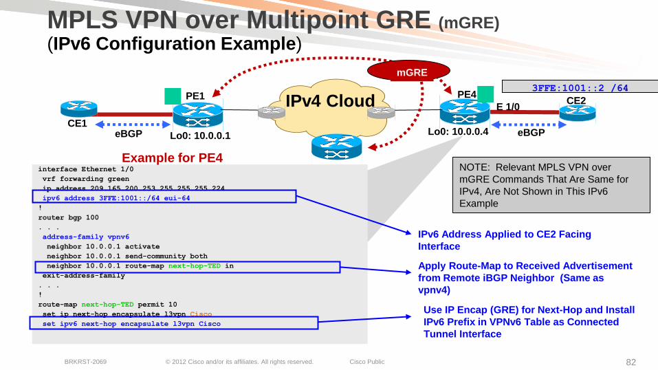
MPLS VPN over Multipoint GRE (mGRE)
(IPv6 Configuration Example)
CE2 PE1 PE4
eBGP eBGP
IPv4 Cloud
Lo0: 10.0.0.1 Lo0: 10.0.0.4
mGRE
Apply Route-Map to Received Advertisement
from Remote iBGP Neighbor (Same as
vpnv4)
IPv6 Address Applied to CE2 Facing
Interface
Use IP Encap (GRE) for Next-Hop and Install
IPv6 Prefix in VPNv6 Table as Connected
Tunnel Interface
CE1
3FFE:1001::2 /64
Example for PE4 NOTE: Relevant MPLS VPN over
mGRE Commands That Are Same for
IPv4, Are Not Shown in This IPv6
Example
E 1/0

© 2012 Cisco and/or its affiliates. All rights reserved. Cisco Public BRKRST-2069 83
Internet Data Center
WAN
P P
PE PE PE PE PE PE
PE PE PE PE PE PE
MPLS-VPN over IP Leveraging MPLS-VPN over mGRE in the Campus
Highly scalable
Usually deployed in large campus networks requiring the definition of a large number of VRFs
Any to any connectivity per user group
User to cloud connectivity
MPLS VPN PE’s still positioned at the distribution layer
VPN traffic is ‘tunneled’ across an IP Core (no MPLS or LDP needed )
Leverages mGRE, so no manual configuration of tunnels needed
Supports mVPN and IPv6
Supported on Catalyst 6500 SUP-2T, targeted at campus deployments
IP
Backbone
Multipoint GRE (mGRE)
MPLS
VPN
Border

© 2012 Cisco and/or its affiliates. All rights reserved. Cisco Public BRKRST-2069 84
MPLS VPN over Multipoint GRE (mGRE)
Summary and Configuration Notes
Solution requires only a single IP address to SP for operation
Solution leverages standard MP-BGP control plane (RFC 4364)
Tunnel endpoint discovery is done via iBGP/route-map
E-BGP can/is still used for route exchange with the SP
Solution requires NO GRE tunnel configuration or LDP
Supports multicast and IPv6 per MPLS VPN model (MDT and 6vPE respectfully)
MVPN Support: ASR 1000, ISR/G2
Supports IPSec for PE-PE encryption (GET VPN or manual SA)
Platform Support
Today: 7600 – 12.2(33) SRE, ASR 1000 (RLS 6), ISR – 15.1(2)T
Future: 6500 (SUP-2T, CY’11), IOS-XR Platforms (Future, Planned)
Branch LAN
VPNv4 Label
over mGRE Encapsulation

© 2012 Cisco and/or its affiliates. All rights reserved. Cisco Public BRKRST-2069 85
MPLS VPN over GRE Solutions Comparison Matrix
MPLS VPN over
mGRE
MPLS VPN over
DMVPN
MPLS VPN over
P2P GRE
Target Deployment Campus/WAN WAN Campus/WAN
MPLS VPN Target VRFs Yes (> 8 VRFs) Yes (> 8 VRFs) Yes (> 8 VRFs)
Uses a Dynamic Endpoint Discovery
Mechanism
Yes (BGP) Yes (NHRP) No
Avoids Manual Full-Mesh GRE
Configurations (mGRE)
Yes Yes No
Requires LDP over the Tunnel No Yes Yes
Current Scaling of End Nodes (Tested) 1000+ (Recommend RRs) EIGRP – 1000 (ASR 1K)
OSPF – 600 (7200)
BGP – 1800 (ASR 1K)
1000+ (Manually
Intensive)
Supports IPSec Encryption Yes (GET, SA) Yes Yes
Supports MVPN Multicast Yes * Yes Yes
Supports IPv6 VPN (6vPE) Yes No (Future) Yes
* DMVPN requires traffic be sent spoke-hub-spoke, if source is located at spoke site

© 2012 Cisco and/or its affiliates. All rights reserved. Cisco Public BRKRST-2069 86
Cisco L3 Virtualization Platforms and Feature Support for WAN and Branch
Cisco ISR-G2
Cisco 7200 ASR 1000 Catalyst 6500 Cisco 7600
VRF Lite S S S S S
VRF Lite over GRE S S S S S
VRF Lite over DMVPN S S S S S
MPLS-VPN S S S S S
MPLS VPN over GRE (P2P)
S S S S (SIP-400),
SUP-2T S (SIP-400,
ES+)
MPLS VPN over DMVPN (mGRE)
S S S S (SIP-400),
SUP-2T S (SIP-400,
ES+)
MPLS VPN over mGRE (BGP)
S S S R (2H’11) SUP-
2T S (SIP-400,
ES+)
Platform Feature
S = Supported Today R = Roadmap

© 2012 Cisco and/or its affiliates. All rights reserved. Cisco Public BRKRST-2069 87 87
Agenda
Network Virtualization Drivers and Building Blocks
Enterprise Campus and WAN Deployment Considerations and Variations
Deployment Solutions for a Virtualized Campus and WAN
QoS Deployment Considerations in a Virtualized Campus and WAN
Recent Innovations at Cisco in Virtualization
Summary

QoS in a Virtualized WAN

© 2012 Cisco and/or its affiliates. All rights reserved. Cisco Public BRKRST-2069 89 89
QoS with GRE, MPLS over GRE ToS Reflection
Router will copy original ToS marking to outer GRE header
For MPLS over GRE, the EXP marking is copied to the outer header of the GRE tunnel
This allows the IPv4 “transport” to perform QoS on the multi-encapsulated packet
IP Payload GRE Original IP Header Outer GRE IP Header GRE Header
GRE (IP Hdr) EXP (MPLS Label) ToS (IP Hdr)
IP Payload Original IP Header
To
S
GRE EX
P
MPLS
Shim Outer GRE IP Header To
S MPLS over GRE
Header with ToS
Reflection
MPLS
Shim EX
P
IP Payload GRE Original IP Header To
S
Outer GRE IP Header To
S
GRE IP Hdr ToS (IP Hdr)
GRE Header with
ToS Reflection

© 2012 Cisco and/or its affiliates. All rights reserved. Cisco Public BRKRST-2069 90 90
QoS Deployment Models in a Virtualized Environment
Aggregate Model
A common QoS strategy is used for all VRFs
i.e. same marking for voice, video, critical data, best effort
Allows identical QoS strategy to be used with/without virtualization
Prioritized VRF Model
Traffic in some VRFs are prioritized over other VRFs (i.e. Production over Guest VRF)
Aggregate vs. Prioritized Model
Following the “Aggregate Model” Allows the Identical QoS Strategy to Be Used With/Without Network Virtualization

© 2012 Cisco and/or its affiliates. All rights reserved. Cisco Public BRKRST-2069 91 91
QoS Models
Connection oriented service
Logical/physical interfaces/connections
Logical - GRE, FR/ATM/Ethernet VC
Virtualization options connection oriented:
VRF-Lite over P2P GRE
MPLS VPN over P2P GRE
* VRF-Lite over DMVPN
* 2547 over DMVPN
Remote Sites
Central
Site
Point-to-Point
Serial 0 Virtual Links
Central
Site
Point-to-Cloud
Remote Sites
No point-to-point (site-to-site) guarantees
Any site can transmit up to ICR into the cloud
Any site can receive up to ECR from the cloud
SLA offers guarantees for conforming traffic
Virtualization options leveraging point-to-cloud:
– MPLS VPNs over mGRE
ICR
ECR
ICR – Ingress Committed Rate
ECR – Egress Committed Rate
* Using per tunnel QoS

© 2012 Cisco and/or its affiliates. All rights reserved. Cisco Public BRKRST-2069 92
QoS Deployment with Network Virtualization Point-to-Cloud Example - Hierarchical QoS + MPLS VPN over mGRE
Branch 1
WAN
Edge
Branch 2
Branch 3
Classify and
Mark Traffic
at Edge
IP VPN
Service
Egress CIR =
600 Mb
Green VRF
Red VRF
Green VRF
Red VRF
Green VRF
Red VRF
LLQ + Shaper
Campus
SiSi
SiSi
Green VRF
Red VRF
1 GE
Voice
Scavanger
Best Effort
Video
HQ/DC mGRE
1st Layer – GRE Tunnel (Parent)
Shaper per GRE
2nd Layer - Service Queuing per GRE (child)
Queuing determines order of packets sent to shaper
H-QoS policy applies to main interface (not mGRE)

© 2012 Cisco and/or its affiliates. All rights reserved. Cisco Public BRKRST-2069 93
Hierarchical QoS Example H-QoS Policy on Interface to SP, Shaper = CIR
600 Mbps
Service Level
Policy-map PARENT
class class-default
shape average 600000000
service-policy output CHILD
Policy-map CHILD
class Voice
police cir percent 10
priority level 1
class Video
police cir percent 20
priority level 2
class Scav
bandwidth remaining ratio 1
class class-default
bandwidth remaining ratio 9
Interface gigabitethernet 0/1.100
service-policy output PARENT
Two MQC Levels
Voice
Video
Best
Effort
Scav
Gig 0/1.100

© 2012 Cisco and/or its affiliates. All rights reserved. Cisco Public BRKRST-2069 96
QoS for Virtualization – Summary
Aggregate QoS model is the simplest and most straight forward
approach (Recommended)
Simplification using the Aggregate model recommends:
Traffic class marking identical to non virtualization scheme
Traffic class marking identical between VRF’s
Leverage H-QoS on virtualized interfaces (GRE, .1Q)
Router dynamically copies ToSEXPToS (GRE)
Prioritized VRF model can be used to prefer traffic originating in one VRF
over another (e.g. guest access, mission critical apps)
Summary: Consider implementing the same QoS approach that is
used for non-virtualized, when deploying QoS in virtualized
enterprise network designs

© 2012 Cisco and/or its affiliates. All rights reserved. Cisco Public BRKRST-2069 97 97
Agenda
Network Virtualization Drivers and Building Blocks
Enterprise Campus and WAN Deployment Considerations and Variations
Deployment Solutions for a Virtualized Campus and WAN
QoS Deployment Considerations in a Virtualized Campus and WAN
Recent Innovations at Cisco in Virtualization
Summary
Easy Virtual Network (EVN)
http://www.cisco.com/go/evn

© 2012 Cisco and/or its affiliates. All rights reserved. Cisco Public BRKRST-2069 99
What Is EVN? Easy Virtual Network (EVN)
VRF VRF VRF
Per VRF: Virtual Routing Table Virtual Forwarding Table
VRF VRF VRF
Consider EVN as a “framework”
1. Offers a dynamic way to configure the “trunk” between two devices for carrying multiple VRF’s
2. Makes the IOS CLI VRF “context aware” for configuration, show, and trouble-shooting commands (debug, traceroute)
3. Simplifies route replication configuration where a “shared” VRF is required (vs. complex BGP import/export)
EVN, like VRF-Lite, still leverages:
VRF aware routing (RIB) and forwarding (FIB)
VRF aware routing protocol processes (EIGRP, OSPF, BGP, RIPv2, static)
VNET Trunk

© 2012 Cisco and/or its affiliates. All rights reserved. Cisco Public BRKRST-2069 100
VRF-Lite and VNET Trunk Compatibility in EVN
VRF-Lite Subinterface Config interface TenGigabitEthernet1/1
ip address 10.122.5.29 255.255.255.252
ip pim query-interval 333 msec
ip pim sparse-mode
logging event link-status
interface TenGigabitEthernet1/1.101
description Subinterface for Red VRF
encapsulation dot1Q 101
ip vrf forwarding Red
ip address 10.122.5.29 255.255.255.252
ip pim query-interval 333 msec
ip pim sparse-mode
logging event subif-link-status
interface TenGigabitEthernet1/1.102
description Subinterface for Green VRF
encapsulation dot1Q 102
ip vrf forwarding Green
ip address 10.122.5.29 255.255.255.252
ip pim query-interval 333 msec
ip pim sparse-mode
logging event subif-link-status
VNET Trunk Config
interface TenGigabitEthernet1/1
vnet trunk
ip address 10.122.5.30 255.255.255.252
ip pim query-interval 333 msec
ip pim sparse-mode
logging event link-status
Global Config:
vrf definition red
vnet tag 101
vrf definition green
vnet tag 102
Both Routers Have VRFs Defined
VNET Router Has Tags
ip vrf red
rd 101:101
ip vrf green
rd 102:102
* RouterEVN# Show derived-config (will display the config
beyond what EVN displays from a simplification perspective
*

© 2012 Cisco and/or its affiliates. All rights reserved. Cisco Public BRKRST-2069 102
EVN - Routing Context – Simplified CLI
Routing Context
Router# routing-context vrf red
Router%red#
Router%red# show ip route
Routing table output for red
Router%red# ping 10.1.1.1
Ping result using VRF red
Router%red# telnet 10.1.1.1
Telnet to 10.1.1.1 in VRF red
Router%red# traceroute 10.1.1.1
Traceroute output in VRF red
IOS CLI
Router# show ip route vrf red
Routing table output for red
Router# ping vrf red 10.1.1.1
Ping result using VRF red
Router# telnet 10.1.1.1 /vrf red
Telnet to 10.1.1.1 in VRF red
Router# traceroute vrf red 10.1.1.1
Traceroute output in VRF red
© 2012 Cisco and/or its affiliates. All rights reserved. Cisco Public BRKRST-2069 103
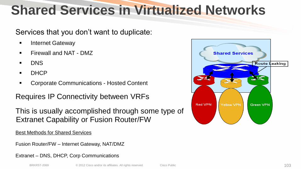
Shared Services in Virtualized Networks
Services that you don’t want to duplicate:
Internet Gateway
Firewall and NAT - DMZ
DNS
DHCP
Corporate Communications - Hosted Content
Requires IP Connectivity between VRFs
This is usually accomplished through some type of Extranet Capability or Fusion Router/FW
Best Methods for Shared Services
Fusion Router/FW – Internet Gateway, NAT/DMZ
Extranet – DNS, DHCP, Corp Communications

© 2012 Cisco and/or its affiliates. All rights reserved. Cisco Public BRKRST-2069 104 104
VRF Simplification - Shared Services
Before: Sharing Servers in
Existing Technologies
Route-Replication Advantage:
• No BGP required
• No Route Distinguisher required
• No Route Targets required
• No Import/Export required
• Simple Deployment
• Supports both Unicast/Mcast
vrf definition SHARED
address-family ipv4
route-replicate from vrf RED unicast all route-map red-map
route-replicate from vrf GREEN unicast all route-map grn-map
After: Simple Shared Service Definition
vrf definition RED
address-family ipv4
route-replicate from vrf SHARED unicast all
vrf definition GREEN
address-family ipv4
route-replicate from vrf SHARED unicast all
ip vrf SHARED
rd 3:3
route-target export 3:3
route-target import 1:1
route-target import 2:2
!
ip vrf RED
rd 1:1
route-target export 1:1
route-target import 3:3
!
ip vrf GREEN
rd 2:2
route-target export 2:2
route-target import 3:3
!
router bgp 65001
bgp log-neighbor-changes
!
address-family ipv4 vrf SHARED
redistribute ospf 3
no auto-summary
no synchronization
exit-address-family
!
address-family ipv4 vrf RED
redistribute ospf 1
no auto-summary
no synchronization
exit-address-family
!
address-family ipv4 vrf GREEN
redistribute ospf 2
no auto-summary
no synchronization
exit-address-family
!

© 2012 Cisco and/or its affiliates. All rights reserved. Cisco Public BRKRST-2069 106 106
EVN - Easy Virtual Network Roadmap
Platform Release FCS Date
ASR1K IOS XE 3.2S Nov 2010
Cat6K – Sup2T 15.0(1)SY1 Q1CY2012
Cat4K – K10 IOS XE 3.3.0 SG Q2CY2012
Cat4K – K5 15.1(1)SG Q2CY2012
Cat6K – Sup720* 15.1(1)SY Q1CY2013
Cat3K-X not ECed
ISR-G2 not ECed
Nexus 7K TBD
All dates are target FCS Vlan ID Re-use shipped on Sup2T in 12.2(50)SY, June 2011
* Sup720 will not support VNET Trunk
“Many of the products and features described herein remain in varying stages of development and will be offered on a when-and-if-available basis. This roadmap is subject to change at the sole discretion of Cisco, and Cisco will have no liability for delay in the delivery or failure to deliver any of the products or features set forth in this document.”

© 2012 Cisco and/or its affiliates. All rights reserved. Cisco Public BRKRST-2069 108
Extending EVN over the WAN Leverage MPLS VPN over mGRE for EVN Extension
EVN does not currently support the VNET trunk to be directly extended over MPLS or GRE today
EVN can leverage existing WAN virtualization technologies available today
The VNET tag can be applied under the “vrf definition” context
The integration of VNET + VRF definition allows full use of “existing” WAN virtualization solutions for VNET trunks
VRF VRF VRF
VRF VRF VRF
VNET Trunk VNET Trunk
WAN

© 2012 Cisco and/or its affiliates. All rights reserved. Cisco Public BRKRST-2069 109
Extending EVN over the WAN Leverage MPLS VPN over mGRE for EVN Extension
R1 R2 OSPF OSPF R3
MP-BGP
Update
mGRE
VNET Trunk
E 1/0 E 0/0
VNET Tag = 10
WAN
On MPLS “PE”, apply the ‘vnet tag’ under the “vrf definition”
This injects the VNET into the VRF and is handled as normal VRF forwarding (over MPLS VPN over GRE in this example) !
vrf definition red
vnet tag 10
rd 1:1
route-target export 1:1
route-target import 1:1
!
!
address-family ipv4
exit-address-family
!
VNET Tag Applied under the “vrf
Definition”
Normal ‘rd’ and ‘route-target’ Applied in
MPLS VPN Case
Injects Routes from VNET Trunk into VRF, Allowing Any VRF
over WAN Solution to Be Applied Using VNET
RR
R4
VNET Trunk

MTU Considerations in a Virtualized WAN

© 2012 Cisco and/or its affiliates. All rights reserved. Cisco Public BRKRST-2069 111 111
MTU Considerations with GRE Tunnels Issues
Fragmentation is unavoidable in some cases
The use of GRE tunnels increase the chances of MTU issues due to the increase in IP packet size GRE adds
PMTUD is used on host (DF = 1) to determine path MTU
There can be a performance impact on the router when the GRE tunnel destination router must re-assemble fragmented GRE
Performance impact includes packet re-assembly of fragmented packets
Common Cases where fragmentation occurs?:
Customer does not control IP path, and segment has MTU less than max packet
Router generates an ICMP message, but the ICMP message gets blocked by a router or firewall (between the router and the sender). Most Common!!
MTU=1000 MTU=1500 MTU=1500 MTU=1500 MTU=1500
S C R1 R2 R3 R4
MTU=1500-24=1476
X

© 2012 Cisco and/or its affiliates. All rights reserved. Cisco Public BRKRST-2069 112 112
Path MTU Discovery (PMTUD) with GRE Example
MTU=1000 MTU=1500 MTU=1500 MTU=1500 MTU=1500
S C R1 R2 R3 R4 1. R1 needs to fragment but original IP has DF=1
2. R1 sends ICMP destination unreachable (Type 3, code 4) to
source IP address at S
1. Upon receive of ICMP unreachable, S will
send maximum 1476 bytes
2. 2nd IP packet is 1476 bytes long
GRE Packet Is Too Large and Is Further Fragmented
(DF=0)
1. R4 reassembles to reconstruct the GRE packet (R4 is the
destination of GRE packets)
2. GRE packet is decapsulated
3. The original IP datagram is forwarded
MTU=1500-24=1476

© 2012 Cisco and/or its affiliates. All rights reserved. Cisco Public BRKRST-2069 114 114
MTU Recommendations Point to Point GRE
Avoid fragmentation (if at all possible)
Consider “tunnel path-mtu-discovery” command to allow the GRE interface to copy DF=1
to GRE header, and run PMTUD on GRE
Set “ip mtu” on the GRE to allow for MPLS label overhead (4-bytes)
If using IPSec, “ip mtu 1400” is recommended
Configure ip tcp adjust-mss for assist with TCP host segment overhead
MTU Setting options:
Setting the MTU on the physical interface larger than the IP MTU
Set IP MTU to GRE default (1476) + MPLS service label (4)
Best to fragment prior to encapsulation, than after encap, as remote router (GRE dest) must
reassemble GRE tunnel packets
interface Ethernet 1/0
. . .
mtu 1500
interface Tunnel0
. . .
ip mtu 1472
Use
Each

© 2012 Cisco and/or its affiliates. All rights reserved. Cisco Public BRKRST-2069 115 115
MTU Recommendations Multipoint GRE
Multipoint GRE (mGRE) interfaces are “stateless”
“tunnel path-mtu-discovery” command is not supported on mGRE interfaces (defaults to DF=0 for MPLS VPN o mGRE)
For the MPLS VPN over mGRE Feature, “ip mtu” is automatically configured to allow for GRE overhead (24-bytes)
Configure ip tcp adjust-mss for assist with TCP hosts (inside interface)
MTU Setting options:
Setting the MTU on the physical interface larger than the IP MTU
Best to fragment prior to encapsulation, than after encap, as remote router (GRE dest) must reassemble GRE tunnel packets
interface Tunnel 0
. . .
Tunnel protocol/transport multi-GRE/IP
Key disabled, sequencing disabled
Checksumming of packets disabled
Tunnel TTL 255, Fast tunneling enabled
Tunnel transport MTU 1476 bytes
IP MTU Technical White Paper: http://www.cisco.com/en/US/tech/tk827/tk369/technologies_white_paper09186a00800d6979.shtml
IP MTU Defaults to 1476
When MPLS VPN over
mGRE Is Used

Campus-to-WAN Virtualization Interconnect

© 2012 Cisco and/or its affiliates. All rights reserved. Cisco Public BRKRST-2069 117 117
Campus-to-WAN Interconnection Interconnect Virtualization Policy WAN Campus
Requirement is needed to integrate and connect the virtualization model between the campus and WAN
Several options exist
Solution chosen evaluates scale and complexity
No solution is a one-size-fits-all
WAN
ASBR
Distribution Blocks
SiSiSiSiSiSiSiSi
SiSi
SiSi SiSi
SiSi
C-PE 3
C-PE 2 AS 1
(iBGP)
C-PE 3
C-PE 4
C-PE x
L3/L2
WAN
Service
mGRE
Interface
Extend
Virtualization
Campus
GRE Tunnel
Campus
ASBR
WAN Supporting MPLS
VPN or VRF-Lite
Campus Running MPLS VPN or
VRF Lite

Locator/ID Separation Protocol (LISP) VPN Extension Option over the WAN
More Details on LISP Covered in Session BRKRST-3045

© 2012 Cisco and/or its affiliates. All rights reserved. Cisco Public BRKRST-2069 123
VPN Option over the WAN Using LISP Locator/ID Separation Protocol (LISP) for VPNs in WAN
Needs:
Highly-scalable VPNs
Remove IGP scaling limitations
for Branch WAN aggregation
LISP Solution:
Offers VPN segmentation + LISP
Allows GETVPN to be leveraged
with LISP forwarding
Integrated Multi-homing
IPv4/IPv6 co-existence
Benefits:
High scale WAN aggregation (1000s of sites)
Minimal State on Branch Routers
ISP Transparency
HQ LISP Site
Internet
Data
Center User
Network
Remote
LISP Site
Remote
LISP Site Remote
LISP Site
Remote
LISP Site . . x1,000 . .
More Details on LISP Covered in Session BRKRST-3045
LISP creates a “Level of indirection” with two namespaces: EID and RLOC
IETF Draft: http://tools.ietf.org/html/draft-farinacci-lisp-12

© 2012 Cisco and/or its affiliates. All rights reserved. Cisco Public BRKRST-2069 124 124
Agenda
Network Virtualization Drivers and Building Blocks
Enterprise Campus and WAN Deployment Considerations and Variations
Deployment Solutions for a Virtualized Campus and WAN
QoS Deployment Considerations in a Virtualized Campus and WAN
Recent Innovations at Cisco in Virtualization
Summary

© 2012 Cisco and/or its affiliates. All rights reserved. Cisco Public BRKRST-2069 125 125
WAN Virtualization—Key Takeaways
The ability for an enterprise to extend Layer 3 (L3) virtualization technologies over the Campus/WAN is critical for today’s applications
VRF-lite and MPLS-VPN’s is key to scalable L3 virtualization extension from HQ to remote branch/WAN sites
The ability to transport VRF-Lite and MPLS-VPN over IP allows flexible transport options, including ability to encrypt segmented traffic
Understanding key network criteria (topology, traffic patterns, VRFs, scale, expansion) is vital to choosing the “optimal” solution for extending virtualization over the WAN
MPLS VPN over mGRE offers simpler, and more scalable, deployment, eliminating LDP, manual GRE, for Campus and WAN
Understand the options for QoS, and the impact of MTU and available tools in IOS for MTU discovery
Begin to understand Cisco innovations (MPLS VPN over mGRE, EVN, LISP Virtualization) and how they can help simplify network virtualization in the WAN/Campus for future designs
Leverage the technology, but “Keep it Simple” when possible

© 2012 Cisco and/or its affiliates. All rights reserved. Cisco Public BRKRST-2069 126 126
Recommended Reading

© 2012 Cisco and/or its affiliates. All rights reserved. Cisco Public BRKRST-2069 127
Complete Your Online Session Evaluation
Complete your session evaluation:
Directly from your mobile device by visiting www.ciscoliveaustralia.com/mobile and login by entering your badge ID (located on the front of your badge)
Visit one of the Cisco Live internet stations located throughout the venue
Open a browser on your own computer to access the Cisco Live onsite portal
Don’t forget to activate your Cisco Live
Virtual account for access to all session materials,
communities, and on-demand and live activities
throughout the year. Activate your account at any
internet station or visit www.ciscolivevirtual.com.

© 2012 Cisco and/or its affiliates. All rights reserved. Cisco Public BRKRST-2069 128