Embed Size (px)
Citation preview

Network Video Recorders Quick Guide
Manual Version: V1.00

Thank you for purchasing our product. If there are any questions, or
requests, please do not hesitate to contact the dealer.
Copyright
Copyright 2016 Zhejiang Uniview Technologies Co., Ltd. All rights
reserved. No part of this manual may be copied, reproduced, translated,
or distributed in any form or by any means without prior consent in
writing from our company.
Trademark Acknowledgement
and other Uniview's trademarks and logos are the property of
Zhejiang Uniview Technologies Co., Ltd. Other trademarks, company
names and product names contained in this manual are the property of
their respective owners.
Disclaimer
CAUTION!
The default password is used for your first login. To ensure account security, please change the password after your first login. You are recommended to set a strong password (no less than eight characters).
To the maximum extent permitted by applicable law, the product
described, with its hardware, software, firmware and documents, is
provided on an "as is" basis.
Best effort has been made to verify the integrity and correctness of
the contents in this manual, but no statement, information, or
recommendation in this manual shall constitute formal guarantee
of any kind, expressed or implied. We shall not be held responsible
for any technical or typographical errors in this manual. The

contents of this manual are subject to change without prior notice.
Update will be added to the new version of this manual.
Use of this manual and the product and the subsequent result shall
be entirely on the user's own responsibility. In no event shall we be
reliable to you for any special, consequential, incidental, or indirect
damages, including, among others, damages for loss of business
profits, business interruption, or loss of data or documentation, or
product malfunction or information leakage caused by cyber attack,
hacking or virus in connection with the use of this product.
Video and audio surveillance can be regulated by laws that vary
from country to country. Check the law in your local region before
using this product for surveillance purposes. We shall not be held
responsible for any consequences resulting from illegal operations
of the device.
The illustrations in this manual are for reference only and may vary
depending on the version or model. The screenshots in this manual
may have been customized to meet specific requirements and user
preferences. As a result, some of the examples and functions
featured may differ from those displayed on your monitor.
This manual is a guide for multiple product models and so it is not
intended for any specific product.
Due to uncertainties such as physical environment, discrepancy
may exist between the actual values and reference values provided
in this manual. The ultimate right to interpretation resides in our
company.
Environmental Protection
This product has been designed to comply with the requirements on
environmental protection. For the proper storage, use and disposal of
this product, national laws and regulations must be observed.

Safety and Compliance Information
Safety Symbols
The symbols in the following table may be found on installation-related
equipment. Be aware of the situations indicated and take necessary
safety precautions during equipment installation and maintenance.
Symbol Description
Generic alarm symbol: To suggest a general safety concern.
ESD protection symbol: To suggest electrostatic-sensitive equipment.
Electric shock symbol: To suggest a danger of high voltage.
The symbols in the following table may be found in this manual.
Carefully follow the instructions indicated by the symbols to avoid
hazardous situations and use the product properly.
Symbol Description
WARNING! Indicates a hazardous situation which, if not avoided, could result in bodily injury or death.
CAUTION!
Indicates a situation which, if not avoided, could result in damage, data loss or malfunction to product.
NOTE! Indicates useful or supplemental information about the use of product.
Safety Information
Installation and removal of the unit and its accessories must be carried
out by qualified personnel. Please read all of the safety instructions
below before installation and operation.

This device is a class A product and may cause radio interference.
Take measures if necessary.
While shipping, the device should be packed in its original packing.
Verify that installation is correct. Incorrect cable connection may
cause personal injury or device damage.
The installation must be made by qualified personnel and should
conform to all the local codes.
If the product does not work properly, please contact your dealer.
Never attempt to disassemble the device yourself. We shall not
assume any responsibility for problems caused by unauthorized
repair or maintenance.
Ensure a proper operating environment, including temperature,
humidity, ventilation and power supply. Make sure the device is
properly grounded and the lightning protection meets
requirements. Keep the device from moisture, dust, strong
electromagnetic radiation and vibration.
Power down the device before connecting and disconnecting
accessories and peripherals.
Protect the power cable from being stepped on or pressed,
particularly at the plug, receptacle, and the part leading out of the
device.
Strictly follow the procedure to shut down the device. Sudden
power failures can cause disk damage and functional abnormalities.
In an environment where power supply is frequently interrupted,
use an Uninterrupted Power Supply (UPS).
Improper use or replacement of the battery may result in hazard of
explosion. Use the manufacturer recommended battery.
Take necessary measures to ensure data security and protect the
device from network attack and hacking (when connected to
Internet). Possible risks and consequences are at user's sole
discretion.

WARNING!
Never look at the transmit laser while the power is on. Never look directly at the fiber ports and the fiber cable ends when they are powered on.
Use of controls or adjustments to the performance or procedures other than those specified herein may result in hazardous laser emissions.
Regulatory Compliance
FCC Part 15
This equipment has been tested and found to comply with the limits for
digital device, pursuant to part 15 of the FCC Rules. These limits are
designed to provide reasonable protection against harmful interference
when the equipment is operated in a commercial environment. This
equipment generates, uses, and can radiate radio frequency energy and,
if not installed and used in accordance with the instruction manual, may
cause harmful interference to radio communications. Operation of this
equipment in a residential area is likely to cause harmful interference in
which case the user will be required to correct the interference at his
own expense.
This product complies with Part 15 of the FCC Rules. Operation is subject
to the following two conditions:
1. This device may not cause harmful interference.
2. This device must accept any interference received, including
interference that may cause undesired operation.

LVD/EMC Directive
This product complies with the European Low Voltage Directive
2006/95/EC and EMC Directive 2004/108/EC.
WEEE Directive–2002/96/EC
The product this manual refers to is covered by the Waste Electrical &
Electronic Equipment (WEEE) Directive and must be disposed of in a
responsible manner.

i
Contents
1 Appearance .......................................................................................... 1
Front Panel and LED Indicators ..................................................................... 1
Rear Panel and Interfaces ............................................................................. 2
2 Installation and Connection .................................................................. 3
Installing Hard Disks ...................................................................................... 4
Replacing a Hard Disk .................................................................................... 5
Installing a Power Module (Optional) ........................................................... 6
Installing a Decoding Card (Optional) ........................................................... 7
Mounting the Device .................................................................................... 8
Connecting the Device .................................................................................. 9
3 Startup and Shutdown .......................................................................... 9
Before Startup ............................................................................................... 9
Startup .......................................................................................................... 9
Shutdown .................................................................................................... 10
4 Setup ................................................................................................. 10
Adding an IP Device .................................................................................... 10
Preview ....................................................................................................... 11
Preview Window Toolbar ................................................................... 11
Status Icons in Preview Window ........................................................ 12
Shortcut Menu .................................................................................... 12
Scheduled Recording .................................................................................. 13
Playback ...................................................................................................... 14
Login to the Web Interface ......................................................................... 14
5 FAQs .................................................................................................. 15
1
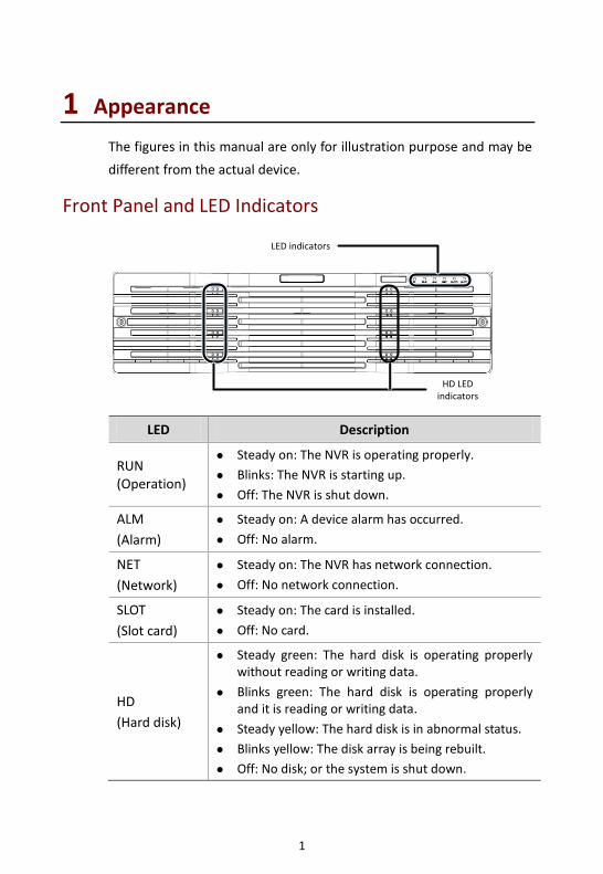
1 Appearance
The figures in this manual are only for illustration purpose and may be
different from the actual device.
Front Panel and LED Indicators
LED Description
RUN (Operation)
Steady on: The NVR is operating properly.
Blinks: The NVR is starting up.
Off: The NVR is shut down.
ALM
(Alarm)
Steady on: A device alarm has occurred.
Off: No alarm.
NET
(Network)
Steady on: The NVR has network connection.
Off: No network connection.
SLOT
(Slot card)
Steady on: The card is installed.
Off: No card.
HD
(Hard disk)
Steady green: The hard disk is operating properly without reading or writing data.
Blinks green: The hard disk is operating properly and it is reading or writing data.
Steady yellow: The hard disk is in abnormal status.
Blinks yellow: The disk array is being rebuilt.
Off: No disk; or the system is shut down.
HD LED indicators
LED indicators

2
LED Description
LINK
(Connection)
Located next to the miniSAS interfaces on the rear panel.
Steady on: Connected to a disk enclosure.
Off: No disk enclosure is connected.
Blinks: The NVR is communicating with the disk enclosure.
Rear Panel and Interfaces
Interface Description
Audio input/output Connect to audio input/output devices.
Power on/off Turn on or off the power.
AC power input
Connects to 100V-240V AC power.
Note: The standard delivery includes one power module. Users may choose to purchase dual power modules as needed.
RS485 Connects to RS485-compliant devices such as a keyboard.
Grounding Connects to ground.
AC power input
Power on/off
USB
Grounding
RS485
RS232
Ethernet
e-SATA
RST
Alarm input
Alarm output
PWR
VGA
HDMI output
miniSAS interface
SFP
Audio input/output
12V DC output

3
Interface Description
SFP 2×1000M optical interfaces, connect to fiber optic cables.
Ethernet 4×10M/100M/1000M auto-negotiation interfaces (RJ45), connect to Ethernet.
RS232 Used for debugging and maintenance.
USB 4xUSB 3.0, connect to USB devices.
e-SATA Connects to an external storage device.
VGA Connects to a VGA display device.
RST Reset button. The NVR will restart if you press and hold this button for at least 5 seconds.
Alarm input 24 channels, connect to alarm input devices.
12V DC output Provide power for an external device.
Alarm output 8 channels, connect to alarm output devices.
PWR Start or shut down the system.
miniSAS interface
2xminiSAS interfaces, connect to disk enclosures.
Note: Do not unplug disk enclosures with power applied.
HDMI Connect to HDMI display devices.
2 Installation and Connection
You need to remove the front panel to install hard disks. Prepare a #1
or #2 Phillips screwdriver.
Please contact your dealer for information about compatible hard
disks.

4
Installing Hard Disks
CAUTION!
Disconnect power before starting installation.
Wear a pair of antistatic gloves or an antistatic wrist strap during installation.
Follow these steps. The figures are only for illustration purpose.
1. Secure the hard disk to a pair of mounting brackets with screws.
Each mounting bracket has a letter L or R on it, indicating left or
right mounting bracket.
2. Unscrew the front panel with a Phillips screwdriver.
3. Align the hard disk with the slot and push in the disk gently.

5
4. Slide the disk gently until it clicks. Repeat the above steps to
install all the hard disks.
5. Attach the front panel and secure it with screws.
Replacing a Hard Disk
CAUTION!
Wear a pair of antistatic gloves or an antistatic wrist strap throughout the procedure.
1. Unscrew the front panel. Gently pull the handles till the hard disk
is detached from the backplane. Wait for at least 30 seconds till
the hard disk stops operation, and then pull the disk out.

6
2. Remove the six fixing screws.
3. Replace the hard disk. See Installing Hard Disks for detailed steps.
Installing a Power Module (Optional)
The NVR supports the 100V-240V AC power module.
CAUTION!
Make sure power is off before you start.
Wear a pair of antistatic gloves or an antistatic wrist strap throughout the procedure.

7
1. Loosen the screw and then remove the blank faceplate.
2. Insert the power module in place.
3. Fasten the screw.
Installing a Decoding Card (Optional)
The NVR supports 4-channel and 6-channel HDMI decoding cards.
CAUTION!
Make sure power is off before you start.
Wear a pair of antistatic gloves or an antistatic wrist strap throughout the procedure.
Do not insert or remove a decoding card with power applied.

8
1. Loosen the two screws and then remove the blank faceplate.
2. Insert the decoding card in place.
3. Fasten the two screws.
Mounting the Device
Mount the NVR in a cabinet. Keep it away from any vibration source
such as an electric generator.
CAUTION!
The cabinet must be installed with a tray or slide rails. Do not use only mounting brackets to hold the NVR.
Do not stack other devices on your NVR or place anything heavy on it. Otherwise heat dissipation will be affected.

9
Connecting the Device
The figure below shows how to connect the NVR to other devices.
3 Startup and Shutdown
Before Startup
To avoid the risks of personal injury and device damage, make sure the
following requirements are met before connecting your NVR to power.
The NVR is properly mounted.
Nothing is placed on the NVR.
All cables are correctly connected.
The power conforms to specifications.
Startup
Connect the NVR to power and then press the power on/off button.
Alarm input device
Fiber optic cable
Analog display device
Network
Digital display device
Mouse
AC power Analog
audio input
Analog audio output
Debug
RS485 device
Alarm output device
Grounding
Disk enclosure
Storage device

10
Shutdown
CAUTION!
Do not disconnect the power supply or press the power on/off button when the NVR is operating or shutting down. This may damage the device.
Click Menu > Shutdown > Shutdown. A message appears. Click Yes.
4 Setup
After the NVR starts up, follow the wizard to complete the basic setup.
CAUTION!
The default password 123456 is intended only for your first login and should be changed immediately after login.
Adding an IP Device
Make sure the IP device to add is connected to your NVR via network.
1. Click Menu > Camera > Camera. The discovered IP devices are
listed.
2. Click for the desired IP device to add it.

11
NOTE!
To search a specified network segment, click Search.
Normally, all the IP devices discovered can be added. If an IP device
is online and live video from it is available, appears in the Status column. Otherwise, check network connection and verify the username and password for the IP device. To modify the username
or password, click for the IP device in the Edit column.
Preview
Preview Window Toolbar
A toolbar appears when you click in a preview window.
Button Name Description
PTZ Control
Click to control the PTZ camera.
This button is effective only for PTZ cameras.
Manual Recording
Click to start video recording to the hard disk
on the NVR. To stop, click .
Instant Playback
Click to start playing the video recorded within the last 5 minutes and 30 seconds.
Zoom
Click to zoom in on a certain area of the image.
Image Config Click to change image settings.
Preview Snapshot
Click to take a snapshot.
To view and back up snapshots, click Menu > Backup > Image.
-
Move the mouse cursor over the button to view channel information.
Two-Way Audio
Click to establish two-way audio with the
camera. To stop two-way audio, click .
Turn on audio
Click to turn on audio. When audio is turned
on, the button is replaced by . To turn
off audio, click .
Switch Camera Click to change the camera in live view.

12
Button Name Description
Exit Click to exit the toolbar.
Status Icons in Preview Window
The following icons indicate alarm, recording and audio status.
Icon Description
Tampering alarm
Motion detection alarm
Recording
Two-way audio
Audio is on
Shortcut Menu
A shortcut menu appears when you right-click a preview window.
Menu Description Screenshot
Menu Display the main menu.
Single Window Choose a camera for live video in full screen.
Multi-Window Choose the desired view.
Corridor Choose the desired view in corridor mode.
Previous Screen
Next Screen
Switch to the previous or next screen.
Start Sequence
Stop Sequence
Display live video in preview windows screen by screen.
Add IP Camera Open the camera window to add a camera.
Playback Play the current day's recording

13
Menu Description Screenshot
for the camera linked to the current preview window.
Output Mode Choose a desired output mode for live view.
Scheduled Recording
1. Click Menu > Storage > Recording.
2. Select the desired camera, select Enable Schedule, and then click
Edit.
3. Set the recording time and type as needed. Review the settings
and then click OK.
NOTE!
Before selecting a recording type other than Normal, you need to enable the corresponding alarm type and configure alarm-triggered recording first. For example, if you select Motion from the Type drop-down list, you need to verify that motion detection and alarm-triggered recording have been enabled. For more details, please refer to the Network Video Recorders User Manual.

14
4. Click Apply to complete the configuration.
Playback
Right-click the desired preview window and then choose Playback
from the menu. The current day's recording plays automatically.
Login to the Web Interface
Before you start, check that your PC is connected to your NVR through
network.

15
1. Open the Web browser on your PC and visit the IP address of your
NVR (192.168.1.30 by default). Install the plugin as prompted if it
is the first time you log in. Close all Web browsers when the
installation starts.
2. Enter the correct username and password and then click Login.
The default username is admin and password is 123456.
CAUTION!
The default password is intended only for your first login and should be changed immediately after login.
5 FAQs
Problem Possible Cause and Solution
The plugin cannot be loaded.
Close all your web browsers when installation starts.
Disable the firewall and close the anti-virus program on your computer.
Enable your Internet Explorer(IE) to check for newer versions of the stored pages every time you visit the webpage (Tools > Internet Options > General > Settings).
Add your NVR's IP address to the trusted sites in your IE (Tools > Internet Options > Security).
The camera is offline.
Click Menu > Maintain > System Info > Camera. The cause is displayed in the Status column. Common causes include disconnected network, incorrect username or password, insufficient bandwidth, and failed stream request.
Check network connection and network configurations.
If it indicates incorrect username or password, check that the camera password set in the NVR is the one used to access the camera's Web interface.
If it indicates insufficient bandwidth, delete other online cameras in the NVR.

BOM: 3101C0CF