Embed Size (px)
Citation preview
DRMU000840 – April 2005 – Rev. H
FVMS Network Video Management Software
Installation Manual

Rev. H ii DRMU000840 04/27/05
ISSUE DATE REVISIONS
A October 2003 Initial Release (PCN 1602)
B November 2003 Added instructions for loading software from the CD.
C November 2003 Added S/N to registration information.
D March 2004 Revised for format and content.
E June 2004 Revised for format and content.
F September 2004 Revised for format and content.
G December 2004 Added new features and screenshots.
H April 2005 Revised for format and content.

Rev. H iii DRMU000840 04/27/05
EXPLANATION OF GRAPHICAL SYMBOLS
WARNING: Text set off in this manner indicates that failure to follow directions could result in bodily harm or loss of life.
CAUTION: Text set off in this manner indicates that failure to follow directions could result in damage to equipment or loss of information.
CAUTION: TO REDUCE THE RISK OF ELECTRIC SHOCK, DO NOT REMOVE COVER (OR BACK).
NO USER-SERVICEABLE PARTS INSIDE.REFER SERVICING TO QUALIFIED SERVICE PERSONNEL.
C A U T I O NRISK OF ELECTRIC SHOCK
DO NOT OPEN
TECHNICIAN NOTES
WARNING: Only authorized technicians trained by HONEYWELL should attempt to repair this DVR unit. All troubleshooting and repair procedures that may be shown are for reference and minor repair only. Because of the complexity of the individual components and subassemblies, no one should attempt to make repairs at the component level or to make modifications to any printed wiring board. Improper repairs can create a safety hazard. And any indications of component replacement or printed wiring board modifications may void any warranty.
WARNING: TO REDUCE THE RISK OF ELECTRICAL SHOCK OR DAMAGE TO THE EQUIPMENT:
• DO NOT DISABLE THE POWER GROUNDING PLUG. THE GROUNDING PLUG IS AN IMPORTANT SAFETY FEATURE.
• PLUG THE POWER CORD INTO A GROUNDED (EARTHED) ELECTRICAL OUTLET THAT IS EASILY ACCESSIBLE AT ALL TIMES.
• DISCONNECT THE POWER FROM THE COMPUTER BY UNPLUGGING THE POWER CORD.

Rev. H iv DRMU000840 04/27/05
NOTES:

Rev. H v DRMU000840 04/27/05
TABLE OF CONTENTS
SECTION 1: INTRODUCTION ..................................................................................................................... 1 1.1 PRODUCT DESCRIPTION.............................................................................................................. 1 1.2 PC REQUIREMENTS ...................................................................................................................... 1
1.2.1 FVMS MINIMUM REQUIREMENTS...................................................................................... 1 1.2.2 FVMS RECOMMENDED REQUIREMENTS ......................................................................... 1
1.3 INSTALLING THE FVMS SOFTWARE ........................................................................................... 2 1.4 RUNNING THE APPLICATION ....................................................................................................... 5 1.5 LOGGING IN.................................................................................................................................... 6 1.6 MAIN DISPLAY SCREEN................................................................................................................ 6 1.7 CONNECTION WINDOW ................................................................................................................ 8
SECTION 2: SETUP................................................................................................................................... 11 2.1 DVR OPTIONS SETUP ................................................................................................................. 11 2.2 DVR LIST SETUP.......................................................................................................................... 12
2.2.1 Adding a New Site................................................................................................................ 13 2.3 DVR HEALTH CHECK................................................................................................................... 14 2.4 DVR ALARM MONITOR ................................................................................................................ 15 2.5 DVR ADMIN ................................................................................................................................... 16
2.3.1 Configuring Import/Export Overview .................................................................................... 17 2.3.2 Exporting Settings ................................................................................................................ 17 2.3.3 Importing Settings ................................................................................................................ 17 2.3.4 Restoring/Initializing Settings ............................................................................................... 17
2.6 USER MANAGEMENT .................................................................................................................. 18 2.4.1 Editing Users ........................................................................................................................ 18 2.4.2 Creating a User .................................................................................................................... 18 2.4.3 Editing a User’s Password and Grouping Level................................................................... 19 2.4.4 Applying DVR permissions to users..................................................................................... 19
2.7 FUNCTIONS .................................................................................................................................. 20 2.5.1 Applying a User Level to a Function .................................................................................... 20
2.8 MAIL SETUP.................................................................................................................................. 21 2.6.1 General E-Mail setup............................................................................................................ 21 2.6.1.1 Enabling E-Mail Alarm ...................................................................................................... 21 2.6.2 General E-Mail setup............................................................................................................ 22 2.6.2.1 Creating a User ................................................................................................................. 22 2.6.2.2 Editing a User.................................................................................................................... 22 2.6.2.3 Deleting a User ................................................................................................................. 22 2.6.2.3 Activating a User ............................................................................................................... 23 2.6.3 General E-Mail setup............................................................................................................ 23
SECTION 3: FVMS BASICS ...................................................................................................................... 26

Rev. H vi DRMU000840 04/27/05
3.1 CONNECTING TO A DVR AND VIEWING VIDEO ....................................................................... 26 3.1.1 Connecting to a DVR and Viewing Video............................................................................. 26 3.1.2 Moving Cameras Around on Screen .................................................................................... 26 3.1.3 Removing a Camera from the Live View.............................................................................. 26
3.2 MULTIPLE SCREEN DIVISIONS .................................................................................................. 26 3.2.1 Creating Multiple Screens .................................................................................................... 26
3.3 ADVANCED OPTIONS.................................................................................................................. 27 3.4 USING MULTIPLE WINDOWS (TABS) ......................................................................................... 28 3.5 MULTIPLE MONITOR SUPPORT................................................................................................. 28
3.5.1 Using Multiple Monitors ........................................................................................................ 28
SECTION 4: MAPS..................................................................................................................................... 30 4.1 MAP OVERVIEW........................................................................................................................... 30 4.2 IMPORTING A MAP....................................................................................................................... 31 .3 PLACING CAMERAS, SENSORS AND LINKS ONTO A MAP..................................................... 32
4.3.1 Attaching Cameras and Sensors ......................................................................................... 32 4.3.2 Attaching Map Links ............................................................................................................. 32 4.3.3 Changing Alarm Colors ........................................................................................................ 33 4.3.4 Viewing Video When an Alarm is Activated ......................................................................... 33
SECTION 5: NETWORK BACKUP............................................................................................................ 34 5.1 BACKUP OPTIONS OVERVIEW................................................................................................... 34 5.2 BACKING UP TO A HARD DRIVE ................................................................................................ 35
SECTION 6: SEARCH................................................................................................................................ 36 6.1 SEARCH OVERVIEW (STANDARD SEARCH) ............................................................................ 36 6.2 PERFORMING A BASIC SEARCH ............................................................................................... 38 6.3 SAVE TO JPG OR AVI .................................................................................................................. 38 6.4 PRINTING AN IMAGE ................................................................................................................... 39 6.5 PREVIEW SEARCH....................................................................................................................... 39
6.5.1 Performing a Preview Search .............................................................................................. 40 6.8 MULTIPLE SEARCH...................................................................................................................... 44
6.8.1 Performing a Multiple DVR Search ...................................................................................... 45
SECTION 7: LOG FILES............................................................................................................................ 48 7.1 FVMS LOG..................................................................................................................................... 48
SECTION 8: ALARM MANAGEMENT....................................................................................................... 50 8.1 ALARM MANAGEMENT................................................................................................................ 50
8.1.1 Event List Right Click ........................................................................................................... 51 8.2 SEARCH ALARM WINDOW.......................................................................................................... 52 8.3 ALARM MANAGER CONFIGURATION WINDOW ....................................................................... 53 8.4 CONFIGURING THE DVR............................................................................................................. 54

Rev. H vii DRMU000840 04/27/05
SECTION 9: HEALTH CHECK .................................................................................................................. 56 9.1 HEALTH CHECK ........................................................................................................................... 56 9.2 HEALTH INFORMATION............................................................................................................... 57 9.3 HEALTH CHECK SETTINGS ........................................................................................................ 58 9.4 HEALTH CHECK STATUS ............................................................................................................ 59 9.5 ENABLING HEALTH CHECK ON THE DVR................................................................................. 60 9.6 ENABLING HEALTH CHECK ON THE PC CLIENT ..................................................................... 60

Rev. H viii DRMU000840 04/27/05
NOTES:

Rev. H 1 DRMU000840 04/27/05
SECTION 1: INTRODUCTION
1.1 PRODUCT DESCRIPTION
FVMS software is Network DVR Management Software, a powerful utility that allows 100 or more DVR units to be controlled using one computer. This software allows you to view live video, search saved video, edit and configure setup on each DVR, and import maps of buildings and other locations.
The FVMS software was specifically designed as an Enterprise software solution.
1.2 PC Requirements
1.2.1 FVMS MINIMUM REQUIREMENTS
Due to the Hardware intensive nature of the FVMS software, there are some minimum PC requirements.
• Pentium IV 2.0 GHz+ (or Equivalent)
• 256MB System Memory
• DirectX 8 or Higher
• AGP 128MB Video Card
• Internet or LAN Connection (56K, DSL, Cable Modem, T1, ISDN, etc.)
• TCP/IP Installed
• Microsoft® Windows® 2000, or XP Operating System
• 1024 X 768 Display Resolution
• 16 Bit Color Depth or Better
1.2.2 FVMS RECOMMENDED REQUIREMENTS
• Dual Pentium IV 3 GHz+ architecture (or Equivalent)
• 1 GB+ System Memory
• DirectX 9 or Higher
• AGP 128MB Video Card
• Internet or LAN Connection (DSL, Cable Modem, T1, ISDN, etc.)
• TCP/IP Installed
• Microsoft® Windows® 2000, or XP Operating System
• Multi-Monitor Support
• 1024 X 768 Display Resolution
• 32 Bit Color Depth
Rev. H 2 DRMU000840 04/27/05
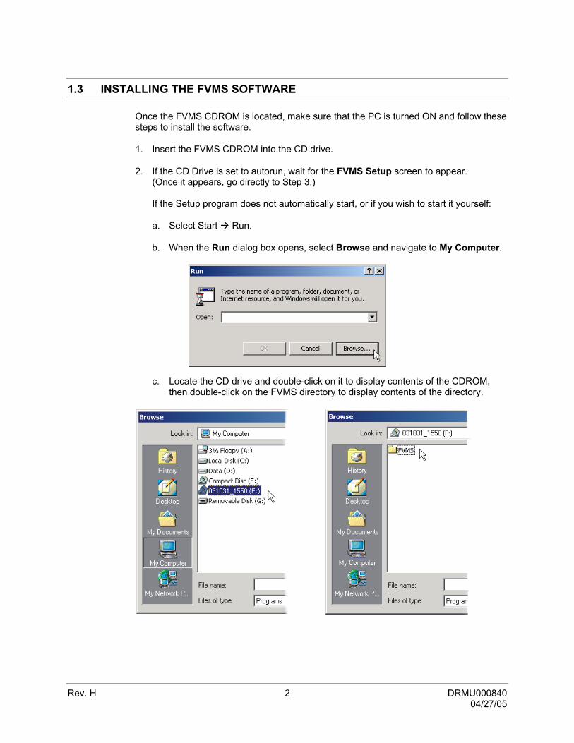
1.3 INSTALLING THE FVMS SOFTWARE
Once the FVMS CDROM is located, make sure that the PC is turned ON and follow these steps to install the software.
1. Insert the FVMS CDROM into the CD drive.
2. If the CD Drive is set to autorun, wait for the FVMS Setup screen to appear. (Once it appears, go directly to Step 3.) If the Setup program does not automatically start, or if you wish to start it yourself:
a. Select Start Run.
b. When the Run dialog box opens, select Browse and navigate to My Computer.
c. Locate the CD drive and double-click on it to display contents of the CDROM, then double-click on the FVMS directory to display contents of the directory.

Rev. H 3 DRMU000840 04/27/05
1.3 INSTALLING THE FVMS SOFTWARE, CONTINUED
d. Double-click SETUP.EXE (or click once and select Open).
e. The Run window will fill in the path and file name for the Setup application. Press OK to run Setup.
f. The following window may be briefly seen showing that FVMS is preparing the InstallShield® Wizard. Once it loads, the Setup Wizard will launch.

Rev. H 4 DRMU000840 04/27/05
1.3 INSTALLING THE FVMS SOFTWARE, CONTINUED
3. The Setup program will begin by determining the destination folder for installing the FVMS software. Press Next > to accept the default location.
4. Select the Program Folder in which the program icons should be used. The default setting is to create an FVMS folder for the icons. Press Next > to accept the default setting.

Rev. H 5 DRMU000840 04/27/05
1.3 INSTALLING THE FVMS SOFTWARE, CONTINUED
5. The Setup process will notify you when FVMS is installed. Press Finish to complete Setup and close the installer window.
1.4 RUNNING THE APPLICATION
To run the FVMS software, select Start Programs FVMS. Until the software is registered, a reminder will display that this is a trial version.
To register the software, select About Register FVMS from the main menu to get the Registration Key #. Send an email to [email protected] with the following:
• Company Name • Company Phone Number • Email address for notification of updates • Registration Key # • Serial Number (S/N) from box or CD case label
Click on the to close the About Register FVMS window. Once you receive the Authorization Code from Honeywell.com, return to About Register FVMS, enter the Authorization Code and select Register to complete the registration process.
Rev. H 6 DRMU000840 04/27/05
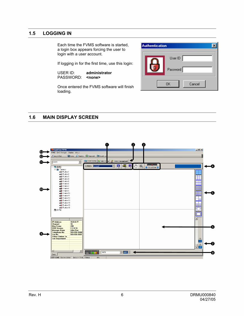
1.5 LOGGING IN
Each time the FVMS software is started, a login box appears forcing the user to login with a user account.
If logging in for the first time, use this login:
USER ID: administrator PASSWORD: <none>
Once entered the FVMS software will finish loading.
1.6 MAIN DISPLAY SCREEN

Rev. H 7 DRMU000840 04/27/05
1.6 MAIN DISPLAY SCREEN, CONTINUED
1 Screen Toggle Allows creation and viewing of additional screens. A
Screen is a customizable collection of (up to) 36 cameras. Multiple screens may be created.
2 Screen Tabs Organize the open Windows. multiple screens may be open (such as MAPs, Log Viewer, Live View, and Search) change to them by simply clicking on the tabs.
3 Additional Options These are additional options such as ZOOM, DRAG, and RESIZE.
4 Selected Camera Displays information about the camera currently selected.
5 Screen Division Buttons
Allows the viewing one or more sets of cameras at a time.
6 Camera Display Area Displays up to 36 cameras. The user can move cameras around simply by dragging it to a new square.
7 Page/Channel Each 36 Camera view can be separated into multiple split screens. These screens are called pages (ex. The 4x4 split would have a total of 9 Pages). The Channel is simply the order of the camera in the 36 Channel Camera view.
8 Audio Control
9 DVR Detail Information
10 Connection Window Displays all the current DVRs setup on the FVMS software.
11 DVR Selector
12 Toolbar This toolbar contains the most frequently used options, such as Search, Maps, Alarm Log, etc.
13 Menu Options The Menu Options contain all the available options for configuring and viewing cameras.

Rev. H 8 DRMU000840 04/27/05
1.7 CONNECTION WINDOW
The Connection window displays the current DVRs configured in the Site List. The DVRs can be displayed with all the cameras showing or can have the cameras minimized.
1 DVR Site Displays the Site Name of the DVR. To hide the cameras select the + or – next to the icon
2 Camera Folder
Displays the folder that contains the Cameras
3 Cameras Displays the cameras attached to the DVR unit.
Camera not being displayed
Camera currently being displayed
Camera offline
1
2
3
Right clicking on the DVR brings up several options:
Connect DVR Opens a connection to the DVR. A connection is required before viewing cameras on the DVR.
Disconnect DVR Closes an Open connection to the DVR. Connect All Camera Connects to all camera channels on the DVR. Disconnect All Camera Disconnects all camera channels on the DVR. DVR Configuration Opens setup on the select DVR unit
Network Backup Opens the BACKUP window which allows the operator to locally save video which is located on the DVR
Show Search Display Opens the search window with the current DVR already selected.

Rev. H 9 DRMU000840 04/27/05
1.7 CONNECTION WINDOW, CONTINUED
Close Search Closes a currently open search window.
Controls Displays the Control Outputs for the select DVR and allows activation of them.
Right clicking on a camera in the Connection Window brings up several options:
Show Live Places the selected camera onto the MAIN DISPLAY AREA.
Show New Window Open the selected camera in its own window.
Pause Live Pauses the selected camera on its current image.
Restart Live Begins playing the video that has been paused.
Close Live REMOVES THE CAMERA FROM THE MAIN DISPLAY AREA
Show Search Display
Opens the search window with the current DVR already selected.
Close Search Closes a currently open search window.
Show PTZ Control Opens the PTZ controller.

Rev. H 10 DRMU000840 04/27/05
NOTES:

Rev. H 11 DRMU000840 04/27/05
SECTION 2: SETUP
2.1 DVR OPTIONS SETUP
The Options Menu is where you may configure connection and user settings.
1 Menu Menu of configurable options.
2 User Information Displays current user information.
3 Load/Save Options Auto load and save options when logging on and off..
4 Live Display Configure live display options.
5 Change Password Change the password of current user logged on.
6 Map Alarm Event Configure Map Alarm Event Options.

Rev. H 12 DRMU000840 04/27/05
2.2 DVR LIST SETUP
As many as 100 DVR units can be connected to the FVMS at any given time.
1 Mgr Name Name of the Manager of the DVR or DVR Location.
2 Tel No Telephone number of the DVR location
3 Fax No Fax number of the DVR location.
4 Police Station No Number of Police Station local to DVR.
5 Fire Dept No Number of Fire Dept. local to DVR.
6 Add Saves the settings after adding a new site.
7 Update Saves any settings that have been edited.
8 Delete Deletes a current site.
9 DVR Group Specifies the group that the DVR unit is in.
10 Password Administrator password to the DVR unit.
11 DVR Port Used to enter the port that the DVR uses to transfer the data. The port is specified inside the Communication setup on the DVR.
12 IP/URL Specifies the IP Address of the DVR. Used to connect to the DVR.
13 DVR Name Name used to easily identify the DVR unit. i.e., Exxon E Sprague
14 DVR List Displays the current list of added DVRs.
15 Quick Jump Menu Allows user to jump between option menus.
Rev. H 13 DRMU000840 04/27/05
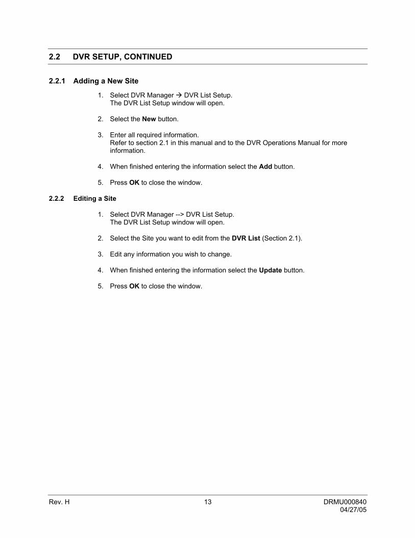
2.2 DVR SETUP, CONTINUED
2.2.1 Adding a New Site
1. Select DVR Manager DVR List Setup. The DVR List Setup window will open.
2. Select the New button.
3. Enter all required information. Refer to section 2.1 in this manual and to the DVR Operations Manual for more information.
4. When finished entering the information select the Add button.
5. Press OK to close the window.
2.2.2 Editing a Site
1. Select DVR Manager --> DVR List Setup. The DVR List Setup window will open.
2. Select the Site you want to edit from the DVR List (Section 2.1).
3. Edit any information you wish to change.
4. When finished entering the information select the Update button.
5. Press OK to close the window.

Rev. H 14 DRMU000840 04/27/05
2.3 DVR Health Check
The DVR Health check option allows for scheduled DVR health checks. The health checks can be scheduled to check in intervals and by levels.
1 Password Sets a password for the DVR units PPP.
2 User Name Sets a user name for the DVR units PPP.
3 Phone Number Sets a phone number for the DVR units PPP
4 Health Check Port Selects the Health Check Port for the DVR unit.
5 Update Updates the information for the DVR unit
6 Use Health Check Allows Health Check to run on the selected DVR unit.
7 Open/Test Opens an outside .wav file and tests functionality.
8 Voice Warning on Failure
Enables voice warning on failure, runs selected .wav file.
9 Failure Sets the amount of failures before a specific action will be taken.
10 Warning Sets the amount of warnings before a specific action will be taken.
11 Check Level Specifies and checks the levels of Video Loss, Recording

Rev. H 15 DRMU000840 04/27/05
Failures, and Disk Space.
12 Video Loss count Enables Video Loss Count to a specified warning and failure level.
13 Record Failure Count
Enables Recording Failure Count to a specified warning and failure level.
14 Disk Free Space (%)
Enables Disk Free Space (%) to a specified warning and failure level.
15 Check Every Once Sets the Check Interval to a specified day of the week, hour or minute.
16 Enable Health Check
Enables health check for the DVR units.
17 Modem Warning Sound
Selects a specific modem to alert the user upon warning.
18 DVR Check List Lists the DVR’s that are connected to the FVMS and have the health check enabled.
19 Use PPP Enables Point-to-point Protocol for the selected DVR unit.
2.4 DVR Alarm Monitor
DVR Alarm Monitor option allows the user to specify the alarm settings for the DVR units.

Rev. H 16 DRMU000840 04/27/05
1 User Emergency Alarm
Enables the use of the Emergency Alarm.
2 Save Directory Specifies a directory to save the alarm data.
3 Save Every Specifies weather to save alarm data every day or after a set amount of hours.
4 Network Specifies the network port number.
5 Notice Turns on the popup messenger notice.
6 Sound Option Allows for no sound, beep or .wav file play upon notice.
7 Add Adds specified name to the Alarm Resolution List.
8 Update Updates Alarm Resolution List.
9 Delete Deletes listing from the Alarm Resolution List.
2.5 DVR Admin
The Options Menu is where you may configure connection and user settings.
1 Global Settings Configure global DVR settings
2 Configuration Import/Export
Import or export Configuration, Log, or Map Files to or from the DVR.
3 Configuration Restore
Restore and initialized the last configuration in effect upon login.
Rev. H 17 DRMU000840 04/27/05
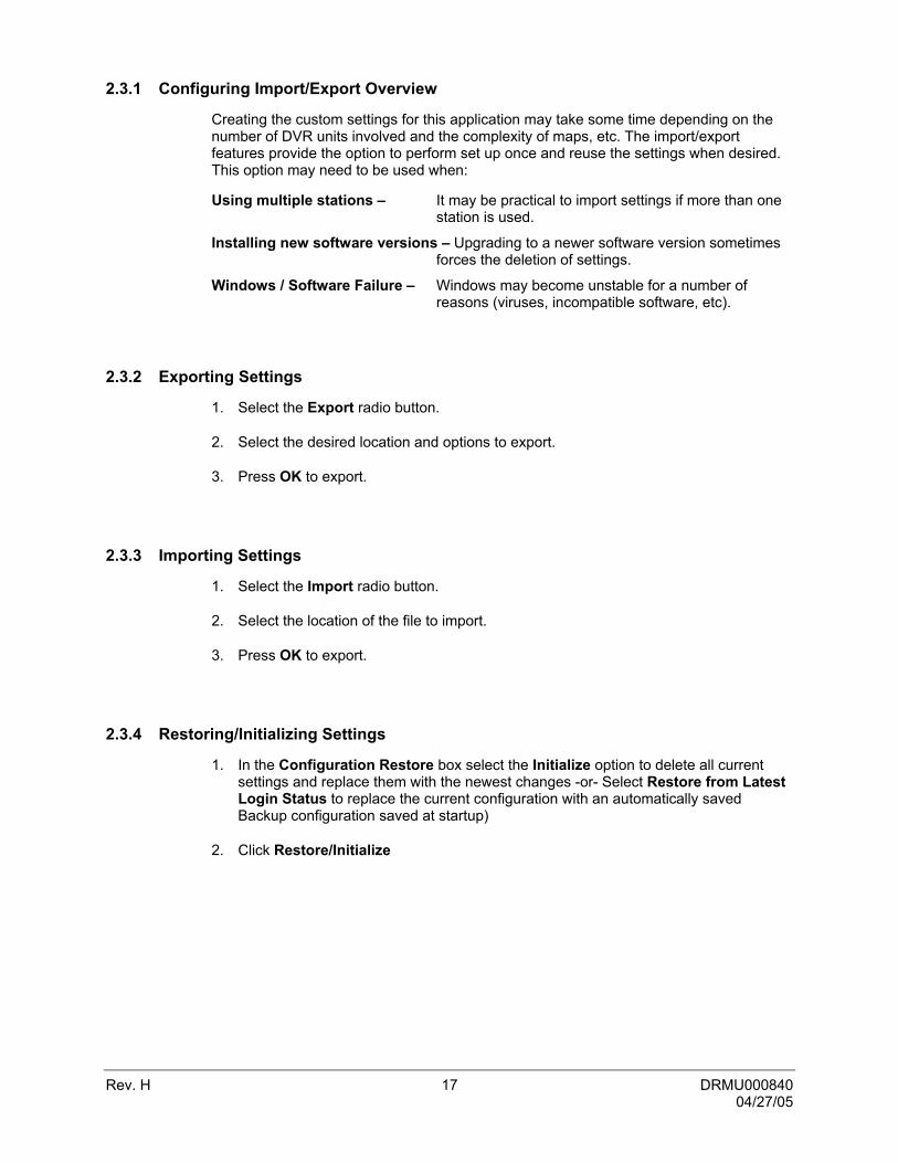
2.3.1 Configuring Import/Export Overview
Creating the custom settings for this application may take some time depending on the number of DVR units involved and the complexity of maps, etc. The import/export features provide the option to perform set up once and reuse the settings when desired. This option may need to be used when:
Using multiple stations – It may be practical to import settings if more than one station is used.
Installing new software versions – Upgrading to a newer software version sometimes forces the deletion of settings.
Windows / Software Failure – Windows may become unstable for a number of reasons (viruses, incompatible software, etc).
2.3.2 Exporting Settings
1. Select the Export radio button.
2. Select the desired location and options to export.
3. Press OK to export.
2.3.3 Importing Settings
1. Select the Import radio button.
2. Select the location of the file to import.
3. Press OK to export.
2.3.4 Restoring/Initializing Settings
1. In the Configuration Restore box select the Initialize option to delete all current settings and replace them with the newest changes -or- Select Restore from Latest Login Status to replace the current configuration with an automatically saved Backup configuration saved at startup)
2. Click Restore/Initialize

Rev. H 18 DRMU000840 04/27/05
2.6 USER MANAGEMENT
The FVMS allows user privileges to be defined. User privileges are defined using two groups, General users and Power users. The General Users group has fewer privileges than the Power User group. Inside the Functions Wizard window, the groups can be custom-defined according to a preset series of options.
2.4.1 Editing Users
1 User Information Enter and Edit user accounts.
2 DVR Access Permissions
View DVRs you may provide access permissions to.
2.4.2 Creating a User
1. In the User window, enter a username in the USER ID box.
2 Enter and confirm the PASSWORD.
3 Select a USER LEVEL (G for General User or P for Power User).
4 Click Add
5 The user just created is now listed in the DVR Access Permission window.
6 OK to return to the main screen.

Rev. H 19 DRMU000840 04/27/05
2.4.3 Editing a User’s Password and Grouping Level
1. Click on the user you wish to edit.
2. Perform the desired changes.
3. Click edit to make the changes permanent.
2.4.4 Applying DVR permissions to users
1. Select the user you wish to provide permissions
2. Check the checkboxes next to DVRs in the DVR Access Permission Window you wish the user to have access to..
3. Click the Apply Permissioon to Selected User button.

Rev. H 20 DRMU000840 04/27/05
2.7 FUNCTIONS
To open the FVMS options select FVMS FVMS Options.
1 Functions List List all DVR function you may assign User Levels to.
2 User Level Sets the user level for a given function.
2.5.1 Applying a User Level to a Function
1. Select the function you wish to apply a user level to
2. Set the user level as either General or Power.
3. Click the Alter button.
4. Click Restore to return all Functions to their previous state.
5. Click Initialize to confirm and save changes to Function levels.

Rev. H 21 DRMU000840 04/27/05
2.8 MAIL SETUP
The E-Mail window allows you send e-mail alerts to users based on alarm events.
2.6.1 General E-Mail setup
The General Tab on the E-mail Setup Window allows you to enable e-mail alarms and configure e-mail settings.
1 Enable E-Mail Alarm Enables the E-Mail Alarm option.
2 Send User Sets the name and address used for sending E-Mails.
3 Primary SMTP Primary SMTP information settings.
4 Secondary SMTP Secondary SMTP information settings.
2.6.1.1 Enabling E-Mail Alarm
1. Check the Enable E-Mail Alarm box.
2. Enter the From Name and E-Mail address you wish to use.
3. Enter the Primary SMTP Settings and click Test.
4. Enter the Secondary SMTP settings if they are available and click Test.

Rev. H 22 DRMU000840 04/27/05
2.6.2 General E-Mail setup
The User Tab on the E-mail Setup Window allows you to specify recipients of e-mail alerts.
1 E-Mail Recipients Displays all users set to receive e-mail notifications of alarm events.
2 User Management Allows add, edit, and delete e-mail recipients.
3 Enable E-Mail Alarm Enables the E-Mail Alarm option.
2.6.2.1 Creating a User
1. Enter the Users name into Name text box.
2. Enter the E=Mail address you wish alarm alerts to be sent to.
3. Click Add
2.6.2.2 Editing a User
1. Select the User you wish to edit.
2. Edit the users name or E-Mail address.
3. Click Edit.
2.6.2.3 Deleting a User
1. Select the User you wish to delete.
2. Click Delete.

Rev. H 23 DRMU000840 04/27/05
2.6.2.3 Activating a User
1. Select the checkbox next to the User you wish to receive e-mails.
2.6.3 General E-Mail setup
The Normal Alarm Tab on the E-mail Setup Window allows you to enable e-mail alarms to be sent when normal alarm events occur.
1 Enable E-Mail Enables the E-Mail Alarm option.
2 E-Mail on Event Activates the send e-mail on Normal Alarm event feature.
3 Event Selections Selects which Alarm Events will trigger an e-mail.

Rev. H 24 DRMU000840 04/27/05
The Emergency Alarm Tab on the E-mail Setup Window allows you to enable e-mail alarms to be sent when Emergency alarm events occur.
1 Enable E-Mail Enables the E-Mail Alarm option.
2 E-Mail on Event Activates the send e-mail on Normal Alarm event feature.
3 Event Selections Selects which Alarm Events will trigger an e-mail.
The Health Check Alarm Tab on the E-mail Setup Window allows you to enable e-mail alarms to be sent when Emergency alarm events occur.
1 Enable E-Mail Enables the E-Mail Alarm option.
2 E-Mail on Event Activates the send e-mail on Normal Alarm event feature.
3 Event Selections Selects which Alarm Events will trigger an e-mail.

Rev. H 25 DRMU000840 04/27/05
NOTES:

Rev. H 26 DRMU000840 04/27/05
SECTION 3: FVMS BASICS
3.1 CONNECTING TO A DVR AND VIEWING VIDEO
Once the DVR has been added as a Site, connecting to it is easy.
3.1.1 Connecting to a DVR and Viewing Video
1. Right-click on a DVR inside the Connection Window (See Section 1.2) and select the Connect Site option. Icons representing cameras will be displayed beneath the DVR in the Connection Window.
2. Drag a camera to view onto the Main Display Area.
3.1.2 Moving Cameras Around on Screen
To move cameras around, drag them from one location to another on the screen.
3.1.3 Removing a Camera from the Live View
Right-Click on the camera and select Close.
3.2 MULTIPLE SCREEN DIVISIONS
The FVMS software allows the operator to create several groups of cameras and customize the organization of the cameras. These screens can be selected from the SCREEN dropdown menu.
Each Screen can contain up to 36 different cameras, and the Screen Division buttons will affect only the selected screen. Screen names are saved by opening the FVMS Options and selecting the Save Live Display Settings button. If the Auto Save on Log-In and Auto Save on Exit options are checked then simply Log-Off or Close FVMS to save the settings.
3.2.1 Creating Multiple Screens
1. Click the blue Monitor icon next to the SCREEN dropdown list to open the Screen Position Name window.
2. Type a name into the text field,
then select Add.
3. Continue adding as many new Screens as necessary.

Rev. H 27 DRMU000840 04/27/05
3.3 ADVANCED OPTIONS
Some advanced options are available
.
1 Hand The hand is selected by default. This option allows the operator to drag live cameras from one location to another.
2 ZOOM When this option is selected dragging the mouse around a portion of the video will zoom in on the image. Zoom out by right-clicking on the image and selecting original size.
3 Adjust Size Deletes a selected map from the Map Manager.
Right-clicking on the video will bring up the available options.
Start Begins playing the video that has been paused.
Pause Pauses the selected camera on its current image.
Original Size Zooms out to its default size.
All Original Size Zooms all cameras out to their default size.
Extended Size Extends the selected camera to the maximum available size within the current window.
Real Size Resizes the selected camera to its original true size.
Show New Window Opens the selected camera in its own window.
Entire Screen / Normal Screen
Maximizes the current camera view to Full Screen (eliminating everything but the video). To return the regular screen right-click again and choose Normal Screen.
Open Search Opens the search window with the current DVR already selected.
Show PTZ Control Opens the PTZ controller

Rev. H 28 DRMU000840 04/27/05
3.4 USING MULTIPLE WINDOWS (TABS)
The FVMS software can now have multiple windows open at any given time. The organization of these windows is done by using Tabs, and by clicking on a given tab you can jump from one window to another.
3.5 MULTIPLE MONITOR SUPPORT
Multiple monitors may be used with the FVMS Software. This can be beneficial if keeping the Map Editor open, the Search window open, and the Live View open at the same time.
Most Microsoft Operating Systems support multiple monitors but your Video Card may need to be upgraded to support more than one display. Contact your local computer vendor or IT Director for more information.
3.5.1 Using Multiple Monitors
1. Click on a Tab.
2. With the mouse still over the Tab, hold down the left mouse button and drag the Tab to another monitor.
3. Maximize the Tab by selecting the Maximize button on the top right corner of the window.

Rev. H 29 DRMU000840 04/27/05
NOTES:

Rev. H 30 DRMU000840 04/27/05
SECTION 4: MAPS
4.1 MAP OVERVIEW
The FVMS software is capable of importing maps and associating cameras and sensors to locations on the map, as well as linking maps together This feature was designed to allow users to quickly identify alarm zones and view the associated video.
1 Map Chooser Select a map to view it on screen.
2 Camera, Sensor, and Link Icons
Displays Icons that can be dragged onto a map to represent cameras, sensors, or create map links.
3 Clear All Cameras Clears any cameras that have been placed on the map.
4 Clear All Sensors Clears any sensors that have been placed on the map.
5 Clear All Maplinks Clears any maplinks that have been placed on the map.
6 Zoom Controls This option resizes the map to its original size.
7 Open in New Window Opens the selected Map in a new window.
8 Delete Deletes a selected map from the Map List.
9 Add Click to import a map to the Map List.
10 Map List Displays all maps currently loaded. Used for add, delete, and Open in New Window features.
1
6
7
8
11
2
9
3
4
5
10

Rev. H 31 DRMU000840 04/27/05
11 Zoom Controls These options adjust the size of the map being displayed.
4.2 IMPORTING A MAP
Import as many maps as you wish. The Maps when imported are listed in alphabetic order. When the need arises for several maps to be imported, it is suggested that they be named in a manner that will allow for easy location.
1. Select Map List button at the top of the screen or the Map Editor tab if it is already open.
2. Click the add button in the lower right hand corner of the screen to open the New Map window.
4. Enter a name into the New Map Name field. Use a name that will quickly identify the map you import.
5. Select the browse icon in the File Name field to open a Browse window.
6. Find the file to import. Supported file types are as follows:
AutoCAD files (up to R14) – DFX, DXF, DWG Standard Image Files – JPG, BMP, EMF, WMF
7. Select the DVR or DVRs the map will be available to.
8. Press OK. The new map should now be displayed in the Map List.

Rev. H 32 DRMU000840 04/27/05
.3 PLACING CAMERAS, SENSORS AND LINKS ONTO A MAP
Placing cameras, sensors, and links on a map allows easy identification of locations where cameras and alarms are located, as well as the ability to link between multiple area maps.
4.3.1 Attaching Cameras and Sensors
1. Select Display Show Map The Map Editor window will open.
2. Select a map from the Map List. The map should now be displayed.
3. Drag a colored camera or sensor icon onto the map. Releasing the cursor will open the Camera (or Sensor) Info window.
4. Use the dropdown menu to select a Site.
5. Use the dropdown menu to select a Camera (or Sensor).
6. Use the dropdown menu to select the Type of Camera (or Sensor).
7. Press OK. The Camera (or Sensor) Info window will close.
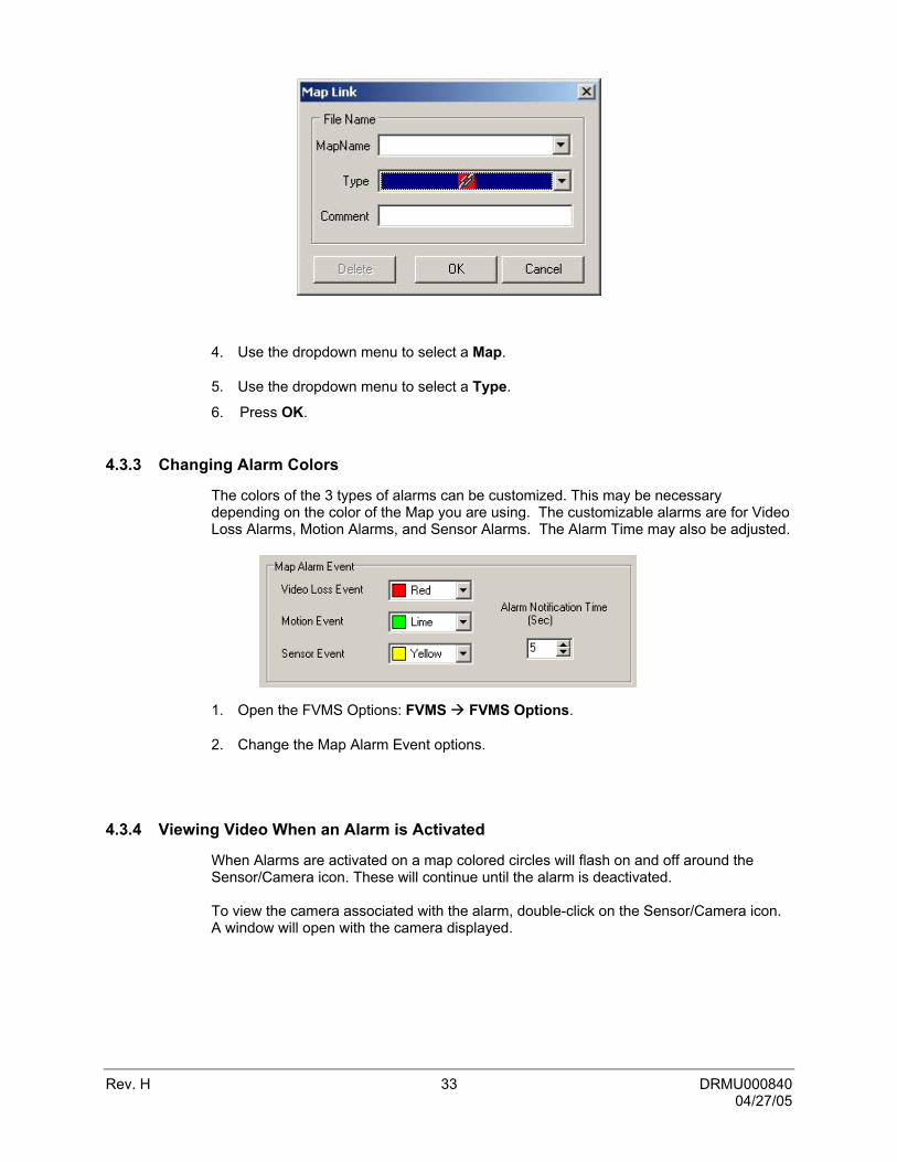
4.3.2 Attaching Map Links
1. Select Display Show Map The Map Editor window will open.
2. Select a map from the Map List. The map should now be displayed.
3. Drag a colored link icon onto the map. Releasing the cursor will open the Link Info window.
Rev. H 33 DRMU000840 04/27/05
4. Use the dropdown menu to select a Map.
5. Use the dropdown menu to select a Type.
6. Press OK.
4.3.3 Changing Alarm Colors
The colors of the 3 types of alarms can be customized. This may be necessary depending on the color of the Map you are using. The customizable alarms are for Video Loss Alarms, Motion Alarms, and Sensor Alarms. The Alarm Time may also be adjusted.
1. Open the FVMS Options: FVMS FVMS Options.
2. Change the Map Alarm Event options.
4.3.4 Viewing Video When an Alarm is Activated
When Alarms are activated on a map colored circles will flash on and off around the Sensor/Camera icon. These will continue until the alarm is deactivated. To view the camera associated with the alarm, double-click on the Sensor/Camera icon. A window will open with the camera displayed.
Rev. H 34 DRMU000840 04/27/05
SECTION 5: NETWORK BACKUP
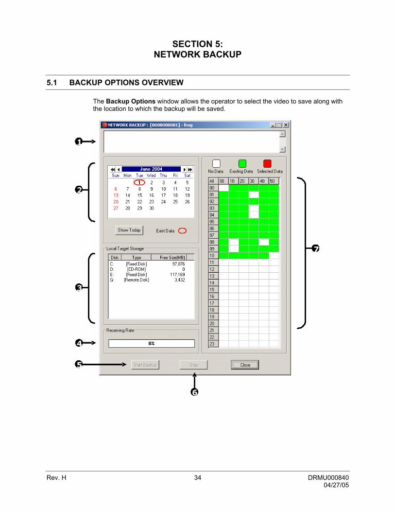
5.1 BACKUP OPTIONS OVERVIEW
The Backup Options window allows the operator to select the video to save along with the location to which the backup will be saved.
1
2
3
4
5
6
7

Rev. H 35 DRMU000840 04/27/05
5.1 BACKUP OPTIONS OVERVIEW, CONTINUED
1 Error Message This box displays any problems encountered with the
current selected options. For example: If the amount of video selected exceeds the storage capacity of the CD-RW Disc, a message will be displayed.
2 Select Day (Calendar) Used to select the day. If video is recorded on a given day, the day will be circled in red. The Current day is always highlighted in red.
3 Select Backup Media
Displays available backup locations. If a formatted CDR or CD-RW disc is inserted, the drive letter and the amount of free storage on the disc will appear. To view all the available Hard Drives on the DVR put a check in the Fixed HDD box. This will include all mapped network drives.
4 Receiving Data (Status bar) Indicates the progress of the backup.
5 Start Backup Begins the backup process
6 Stop Stops a backup that is in process
7 Hour / Minute A 24-hour clock is used for the Hour/Minute chart. This is broken down into 10 minute increments. The color coded boxes represent either, No data, Recorded Data, or Selected Data. (See the Description Box.) Select a time by clicking on one the boxes. Deselect it by clicking on the box again.
5.2 BACKING UP TO A HARD DRIVE
1. Select DVR Manager Network Backup. The Network Backup window will open.
2. Select the day using the Select Day calendar.
3. Select the time(s) to backup by clicking on the desired blocks. The blocks will turn red when selected. To deselect the blocks, simply click on them again.
4. Select a Target Storage device.
5. Press the Start Backup button.
If the amount of video exceeds the storage capacity of the media being used, an error message will be displayed inside the Error Message box. If this happens, reduce the amount of video that is being exported or select another media device that has a larger storage capacity.
Once the Start Backup button is pressed, the Receiving Rate will begin showing the progress.

Rev. H 36 DRMU000840 04/27/05
SECTION 6: SEARCH
6.1 SEARCH OVERVIEW (STANDARD SEARCH)
The FVMS Software has several options that allow easy searching through, to find, a particular section of video. From Motion indexing and Sensor indexing to calendar views showing which days have recorded video, the FVMS Software is designed to help find what you’re looking for quickly.
There are 2 types of Search Windows that can be opened.
Standard Search: This search window provides for searching only one DVR at a time; however, more options such as Preview Search, etc. are available.
Multiple Search: Allows searching video from multiple DVRs simultaneously.

Rev. H 37 DRMU000840 04/27/05
6.1 SEARCH OVERVIEW (STANDARD SEARCH), CONTINUED
1 Audio Buffer In order to ensure audio plays smoothly when playing it remotely, the audio must first be buffered. This means that several seconds of audio are stored locally before actually playing it.
2 Preview Search The Preview search is a Search option that allows a narrowing down recorded video in a 24 Hour period. It breaks down a single day into 24 images, one image for each hour of the day (The images are taken from the first second of each hour). When an image is selected, the ‘hour’ chosen is then broken down into 6 images, one image for every 10 minute increment. Finally when another image is selected, 10 images are displayed, one for every minute within the 10 minute period. From this point, the selected image can be applied to the Main Search.
3 Index Search The Index Search allows a user to perform a search based on criteria such as Sensor, Motion and Instant Record events
4 Status Search The Status Search option displays video in graph format.
5 POS Search The Point of Sale search is an optional component that can be added to the Fusion DVR. The POS functionality utilizes TVS technology. When performing a POS search, a window appears allowing multiple options and criteria for detailed searches. Refer to the TVS POS Manual for instructions.
6 Save Saves a selected image as a JPG file or saves a video clip in an AVI format.
7 Print Prints a selected image.
8 Sync This option synchronizes the video to the real time. This option may discard frames in order to achieve this synchronization.
9 Zoom This option provides zoom control in and out, for the selected camera.
10 Speed Increases and decreases the playback speed.
11 Audio Control Allows selection of audio channels and audio volume.
12 Play Controls Used to view selected video Frame by Frame, Normal Speed, and Fast Forward.
13 Date Opens a calendar window to select a day on which to perform a search.
14 Search Date and Time
Displays the Date and Time of the video being played.
15 Hour / Minute Control Bar
Select the hour by pressing the appropriate button. Select the minute using the sliding bar.

Rev. H 38 DRMU000840 04/27/05
16 Camera Select Buttons
This option toggles to the Camera buttons.
17 Screen Division Buttons
This option toggles to the Screen Division buttons.
6.2 PERFORMING A BASIC SEARCH
Performing a basic search involves simply selecting the date, the time, the camera, and pressing play.
1. Right-click on a DVR or camera and select Show Search Display or click Display Show Search Display.
2. Click the DATE button and select a day from the calendar.
3. Click an HOUR button to select an hour.
4. Select one or more Cameras.
5. Click Play.
Video can now be played forwards, backwards, and frame-by-frame.
6.3 SAVE TO JPG OR AVI
These selections allow for export of single images in the JPG file format or save video clips in an AVI format. Both JPG and AVI file formats are the most commonly used graphical formats today. Virtually every computer offers some type of support for these file formats and therefore make them the most ideal formats to use.
JPG: The format (.jpg) is optimized for compressing full-color or grayscale photographic images. JPG images are 24-bit (16.7 million color) graphics. JPG is used to export a single image or frame.
AVI: AVI image data can be stored uncompressed, but it is typically compressed using a Windows-supplied or third party compression and decompression module called a codec. AVI files save a video clip.
1
2
3
4
5

Rev. H 39 DRMU000840 04/27/05
6.3 SAVE TO JPG OR AVI, CONTINUED
1 JPG File Export a single image or frame.
2 AVI File Save a video clip.
3 AVI Duration Enter duration (in seconds) for recording the AVI file. Although 5 seconds is the longest displayed, a manual time may be entered. There is no limit to the size of AVI that may be exported.
4 Image Quality It may be necessary to reduce the overall size of an AVI file; for example, to email to someone. AVI file sizes can be reduced by reducing the image quality. By reducing the image quality, the AVI video appears more pixilated. When size is not an issue, setting quality to 100 is highly recommended.
5 Export Begins the saving process. Cancel closes the window without exporting.
6.4 Printing an Image
The DVR can print a recorded image to a local or network printer.
1. From the Search screen, stop on the image to print. Double-click the image.
NOTE: Only one camera can be selected at a time for this function to work.
2. Click on the Print button. A Print Options window appears. Depending on the printer being used, there may be several printing options available. Refer to the printer manual for more information.
3. Press the Print button to print the selected images.
NOTE: The message “NO DEFAULT PRINTERS INSTALLED” will display if no printer is installed.
6.5 PREVIEW SEARCH
The Preview Search can be used in a number of circumstances to quickly find an exact moment where an event (such as a theft) occurred. The Preview Search basically gives a 24 Hour visual overview of a single camera by separating a 24 hour period (1 day) into 24 images, one image for each hour of the day. The search can then be further narrowed down into ten minute increments and one minute increments by simply selecting one of the images displayed. The example below shows how the Preview Search functions.
• The first screen has 24 images displayed. Each image represents the first second of each hour. If there is no image recorded during that period, nothing will be displayed.
Rev. H 40 DRMU000840 04/27/05
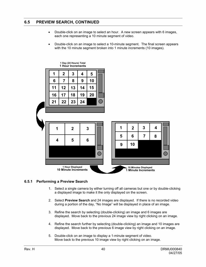
6.5 PREVIEW SEARCH, CONTINUED
• Double-click on an image to select an hour. A new screen appears with 6 images, each one representing a 10 minute segment of video.
• Double-click on an image to select a 10-minute segment. The final screen appears with the 10 minute segment broken into 1 minute increments (10 images).
1 2 3 4 51098 7 6
11 12 13 14 15
16 17 21 22
18 19 2023 24
1 2 3
4 5 6
1
6
1 Minute Increments
2 3 4
5 7 8
9 10
1 Hour Increments
10 Minute Increments 1 Minute Increments 1 Hour Displayed
10 Minutes Displayed
1 Day (24 Hours) Total
6.5.1 Performing a Preview Search
1. Select a single camera by either turning off all cameras but one or by double-clicking a displayed image to make it the only displayed on the screen.
2. Select Preview Search and 24 images are displayed. If there is no recorded video during a portion of the day, “No Image” will be displayed in place of an image.
3. Refine the search by selecting (double-clicking) an image and 6 images are displayed. Move back to the previous 24 image view by right clicking on an image.
4. Refine the search further by selecting (double-clicking) an image and 10 images are displayed. Move back to the previous 6 image view by right clicking on an image.
5. Double-click on an image to display a 1-minute segment of video. Move back to the previous 10 image view by right clicking on an image.

Rev. H 41 DRMU000840 04/27/05
6.5 PREVIEW SEARCH, CONTINUED
6. Use the Play controls to play the video.
7. To Apply the current image to the Main Search (exit out of Preview search with the current image still selected), deselect the Preview Search button
6.6 INDEX SEARCH
Using the Index Search can greatly decrease the amount of time spent searching through saved video. The Index Search allows a user to perform a search based on criteria such as Sensor, Motion and Instant Record events.
1 Select Time The default search time is 24 Hours. If this option is select then a Start Time and End Time must be entered.
2 Multiple camera search
Select one or more cameras to search.
3 Sensor Searches on Sensor Events
4 Motion Searches on Motion Events
5 All Event Searches on all events (sensor, motion, instant recording) for the selected camera(s).
6 Instant Record
Searches on Instant Record Events
7 End Time Specifies the End Time for the Index Search
8 Start Time Specifies the Start Time for the Index Search.
6.6.1 PERFORMING AN INDEX SEARCH
1. Select the Index Search button. The Index Search Option box will open.
2. Select one or more cameras (or check the All Cameras option).
3. Select an event to search (sensor, motion, instant record) or select the All Event option.
4. Press OK. There may be a delay while results are returned. Results will be displayed in a column on the left side of the screen. If no results are found, “NO IMAGE FOUND” will appear in the column.
5. Once the results are displayed, double-click on any one to search through them.

Rev. H 42 DRMU000840 04/27/05
6.6 INDEX SEARCH, CONTINUED
6. Once the desired image is found, apply it to the Main Search by selecting the Close button at the bottom of the results column.
1 Image Display Area Where Search results images are displayed.
2 Search Results Displays the results of the search. Each line represents a segment of video.
3 Type Displays event type: Motion Event Sensor Event Instant Record Event
4 Camera Number Camera number of the returned result.
5 Time Time of the result.

Rev. H 43 DRMU000840 04/27/05
6.7 STATUS SEARCH
The Status Search option displays video in graph format.
1 Camera Displays the cameras in linear format. Scroll down using the scroll bar on the right.
2 Hours The hours 0-23 (24 hours) are listed.
3 Recording Block Displays in blue where video is recorded. Areas of no recording are displayed in white.
6.7.1 PERFORMING A STATUS SEARCH
1. Select the Status Search button to open the Status Search window.
2. Use the mouse to click on an area of the blue recording block. Only one camera can be displayed at a time.
1 2 3

Rev. H 44 DRMU000840 04/27/05
6.8 MULTIPLE SEARCH
The Multiple Search window allows you to search video from multiple DVRs simultaneously.
Standard Search: This search window allows only one DVR at a time to be searched. This option, however, gives you more search options (such as Preview Search, etc)
Multiple Search: Provides for searching video from multiple DVRs simultaneously.
1 Zoom This provides zoom control in and out, for the selected camera.
2 Play Controls Used to view selected video Frame by Frame, Normal Speed, and Fast Forward.
3 Date Opens a calendar window to select a day on which to perform a search.
4 Search Date and Time
Displays the Date and Time of the video being played
5 Hour / Minute Control Bar
Select the hour by pressing the appropriate button. Select the minute using the sliding bar.
6 Screen Division Buttons
This option toggles to the Screen Division buttons.

Rev. H 45 DRMU000840 04/27/05
6.8 MULTIPLE SEARCH, CONTINUED
6.8.1 Performing a Multiple DVR Search
Performing a Multiple DVR search is simple: Select the date, time, and cameras, then press play. Select cameras from different DVRs by dragging them from the Connection Window to the Search Window.
1. From the Display menu select the Shiw Multiple Search window.
2. Click the DATE button and select a day from the calendar.
3. Click and HOUR button to select and hour.
4. Drag one or more Cameras from the Connection Window to the Search window.
5. Click Play.
Video can now be played forwards, backwards, and frame-by-frame.

Rev. H 46 DRMU000840 04/27/05
6.9 PROPRIETARY VIEWER OVERVIEW
The Proprietary Viewer plays back the exported video in its proprietary format. Video saved in this format is extremely difficult to tamper with and therefore is the ideal solution when law enforcement and legal departments are involved. This video cannot be read by any other viewer.
The Proprietary Viewer is essentially the Search portion of the DVR software. For detailed explanation of these functions, refer to Section 6 of the Fusion DVR Operations Manual.
Rev. H 47 DRMU000840 04/27/05
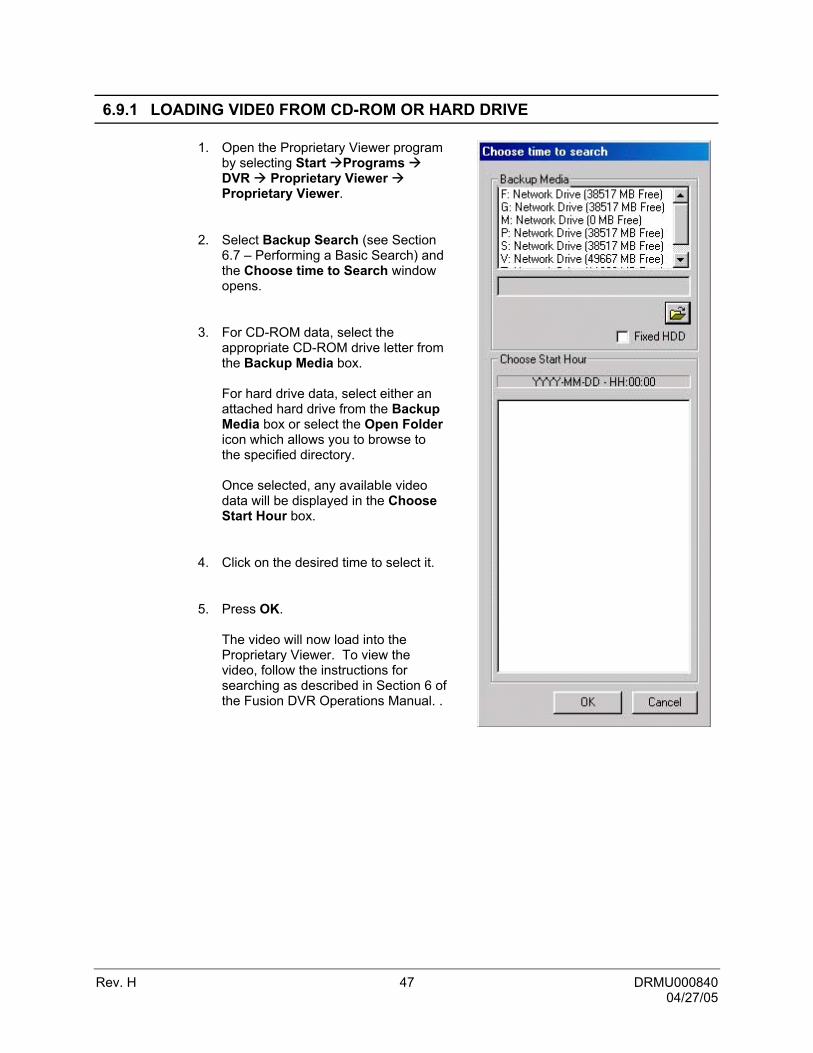
6.9.1 LOADING VIDE0 FROM CD-ROM OR HARD DRIVE
1. Open the Proprietary Viewer program by selecting Start Programs DVR Proprietary Viewer Proprietary Viewer.
2. Select Backup Search (see Section 6.7 – Performing a Basic Search) and the Choose time to Search window opens.
3. For CD-ROM data, select the appropriate CD-ROM drive letter from the Backup Media box. For hard drive data, select either an attached hard drive from the Backup Media box or select the Open Folder icon which allows you to browse to the specified directory. Once selected, any available video data will be displayed in the Choose Start Hour box.
4. Click on the desired time to select it.
5. Press OK. The video will now load into the Proprietary Viewer. To view the video, follow the instructions for searching as described in Section 6 of the Fusion DVR Operations Manual. .
Rev. H 48 DRMU000840 04/27/05
SECTION 7: LOG FILES
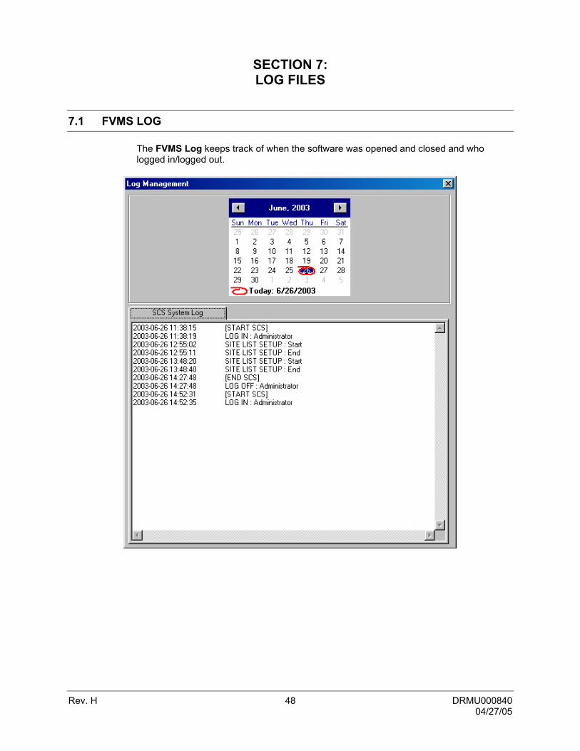
7.1 FVMS LOG
The FVMS Log keeps track of when the software was opened and closed and who logged in/logged out.

Rev. H 49 DRMU000840 04/27/05
NOTES:

Rev. H 50 DRMU000840 04/27/05
SECTION 8: ALARM MANAGEMENT
8.1 ALARM MANAGEMENT
The Alarm Management window is used to view different types of alarms that are coming from the DVR, including Video Signal Loss and Sensor alarms. Use the Filter button to filter through the different types of alarms.
By double-clicking an alarm entry, the search window will open with the associated DVR, camera, and time related to the event already selected.
1 Magnify Increase or decrease the magnification of an image.
2 Display Displays the currently selected Alarm Event.
3 Event List Displays recorded alarm events.
4 Alarm State Filter Filters Events based on their Alarm Status.
5 Event Filter Filters Events based on the date, alarm type, and DVR.
6 Display Attributes Sets the number of video thumbnails displayed and the size they are displayed at.
7 Event Preview Displays thumbnail previews of alarm events.

Rev. H 51 DRMU000840 04/27/05
8.1 ALARM MANAGEMENT, CONTINUED
EVENT LIST ATTRIBUTES
Memo Displays memo info attached to an event.
No The sequential auto-numbering of events.
Time The time the Event was first activated.
Type The type of Event that occurred.
MOTION Displays when motion is detected and is defined as an alarm event on the DVR.
CONTROL Displays when a Control Output has been activated on the DVR.
SENSOR Displays when a Sensor (Alarm) input has been received.
SIGNAL NOT DETECTED Displays when a camera signal is lost.
Camera Name This is the name given to the camera which sent the alarm.
DVR Code This number is auto generated in the DVR List Setup when first added to the FVMS.
DVR Name This is the name given to the DVR when first adding it to the FVMS.
Frames Displays the number of video frames captured for the event.
Operator Displays the operator logged in when the event occurred.
8.1.1 Event List Right Click
1 Default Sets an alarm event to Default. 2 Reviewed Alarm Sets an alarm event to Reviewed. 3 Dismissed Alarm Sets an alarm event to Dismissed. 4 Critical Alarm Sets an alarm event to Critical. 5 Show Alarm Opens event in the Search Alarm Window.

Rev. H 52 DRMU000840 04/27/05
8.2 SEARCH ALARM WINDOW
1 Comment Provides space for user to add comments to video
events. 2 AVI File When selected a video clip exported when Export is
clicked. 3 Export Quality It may be necessary to reduce the overall size of an AVI
file; for example, to email to someone. AVI file sizes can be reduced by reducing the image quality. However, reducing the image quality causes the AVI video to appear more pixilated. When size is not an issue, setting quality to 100 is highly recommended.
4 Export Options These options are only available when AVI export is selected and relate to the export options of the AVI video.
5 Export Exports AVI or JPG file to selected location. 6 Alarm Event
Information Display
Displays the event number and pertinent recorded information related to the alarm event.
7 Playback Controls The play controls allow you to play the video forward, backwards, and frame by frame.
8 Display Displays video playback. 9 Previous Alarm Moves to previous Alarm Event. 10 Continuous
Playing Plays through all alarm events when video playback is initiated. When not selected video playback stops at end of recorded event.
11 Next Alarm Moves to next Alarm Event.
8.2 SEARCH ALARM WINDOW, CONTINUED
Rev. H 53 DRMU000840 04/27/05
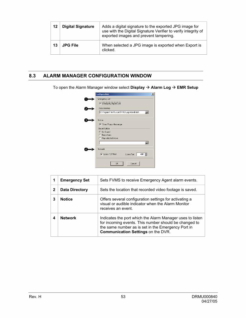
12 Digital Signature Adds a digital signature to the exported JPG image for use with the Digital Signature Verifier to verify integrity of exported images and prevent tampering.
13 JPG File When selected a JPG image is exported when Export is clicked.
8.3 ALARM MANAGER CONFIGURATION WINDOW
To open the Alarm Manager window select Display Alarm Log EMR Setup
1 Emergency Set Sets FVMS to receive Emergency Agent alarm events.
2 Data Directory Sets the location that recorded video footage is saved.
3 Notice Offers several configuration settings for activating a visual or audible indicator when the Alarm Monitor receives an event.
4 Network Indicates the port which the Alarm Manager uses to listen for incoming events. This number should be changed to the same number as is set in the Emergency Port in Communication Settings on the DVR.

Rev. H 54 DRMU000840 04/27/05
8.4 CONFIGURING THE DVR
To enable the Alarm Manager on the DVR follow these steps:
1. Enter SETUP and click the Recording Schedule tab.
2. Select a camera and then associate sensor(s) to that camera using the Sensor checkboxes.
3. Enter the IP Address of the computer running the Alarm Monitor software in the Alarm Options section and set which alarms will be transferred.
4. Click the Network tab and make sure that Disable Remote Control is not checked.
5. The Alarm Monitor uses one port to transfer the data through. The port can be adjusted inside the Network Menu if necessary. It is recommended that unless the port must be changed, that the default setting should be used.
6. Click the Sensor menu tab.
7. Enable the Sensor you wish to use.
8. Adjust the type and delay settings.
9. Click OK.

Rev. H 55 DRMU000840 04/27/05
NOTES:

Rev. H 56 DRMU000840 04/27/05
SECTION 9: HEALTH CHECK
9.1 HEALTH CHECK
The Health Check window is used to view the health of DVRs connected to FVMS.
To view in depth health information or to initiate a manual health check, right click on a DVR in the DVR list and select the appropriate option. Uncheck the Show Current Health Check Status box and select a previous date from the Health History window then select a time from the Health Check Events window to view the health DVRs at that time.
1 Health Check Events
Displays a list of dates and times Health Check was run for the current day. To view an event from a previous day uncheck the Show Current Health Status box and select a new day to view from the Health History window.
2 Health History Displays the dates of all days in which Health check was run and has results for DVRs.
3 Show Current Health Check Status
Displays current health check when selected. If unchecked allows user to access previous Heath check dates to track changes such as hourly storage usage.
4 Check Type Indicates type of check performed (Auto/Manual).
5 DVR List List of DVRs connected to Health Check

Rev. H 57 DRMU000840 04/27/05
9.2 HEALTH INFORMATION
The DVR health information window provides all the collected information related to the health of a DVR at a given point in time. It may be used to track data usage or monitor the stability of a unit over time to determine if components are in need of replacing before a critical failure.
1 Total Status Indicated if the DVR is Healthy and Running correctly.
2 Network Status Indicates if the Network component of the DVR is running correctly and error free.
3 Disk Status Indicates if the hard drives of the DVR are running correctly and the have available storage space..
4 Video Status Indicates if the Video component of the DVR is running correctly and error free.
5 Recording Status Indicates if the Recording component of the DVR is running correctly and error free.
6 DVR Information Displays pertinent information on DVR unit.
7 Video/Recording Displays recording status of cameras on DVR.
8 Memo Space to input notes on Health Check event
9 Disk Usage Indicates disk usage and available space left.
10 Export Exports DVR health information as an HTML document.

Rev. H 58 DRMU000840 04/27/05
9.3 HEALTH CHECK SETTINGS
1 Enable Health Check
Enables Health Check.
2 Check Interval Sets the interval in between executing Health Checks.
3 Modem Select Selects a modem to use for connecting to a DVR if one is present in the PC.
4 DVR List List available DVRs to connect to using Health Check.
5 Check Level Sets Warning and Failure levels for Video, recording, and Disks volume attributes.
6 Voice Warning Enables an audible warning when a warning is detect by a Health Check.
7 Use Health Check Activates Health check for the Selected DVR and sets the Port to Listen over for Health checks.
8 Use PPP PPP configuration for connection to DVRs using a modem.

Rev. H 59 DRMU000840 04/27/05
9.4 HEALTH CHECK STATUS
Upon a warning or failure of any of the Health attributes on the DVR, FVMS will display an icon indicating the type of error which occurred. If selected, the DVR will also sound a voice warning if a failure is detected.
Right click on the DVR and select Show Detail Status to view a further in depth report on the health of the DVR at the recorded time.
If the event you wish to view is not the current recorded Health Check, uncheck the Show Current Health Check Status box, select the time you wish to view in the Health Check Events and/or Health History windows and then right click on the DVR you wish to view in the DVR List window.
1 USE
2 DVR STATUS Indicates the health of the DVR as a whole.
3 NETWORK Indicates the health of the DVR network connection.
4 VIDEO Indicates the health of the DVR video.
5 RECORDING Indicates the health of the recording function.
6 FREE SPACE Indicates the health of the storage space available.
7 MEMO Displays additional notes added to health event.
Healthy
Warning
Failure
Disabled
Healthy
Failure
Warning
Healthy
Failure

Rev. H 60 DRMU000840 04/27/05
9.5 ENABLING HEALTH CHECK ON THE DVR
To enable Health Check on the DVR unit follow these simple steps.
1. Click Setup and select the Network tab.
2. Confirm DVR Site Information is checked in the Web Function section.
3. Click OK.
9.6 ENABLING HEALTH CHECK ON THE PC CLIENT
To enable Health Check on the PC Client follow these simple steps.
1. Click Display HealthCheck Health Check Setting.
2. Click the Use Health Check box in the DVR List Settings section.
3. Select the DVR unit you wish to perform Health Check on in the DVR List section.
4. Perform any other changes to the Check Interval or Check Level.
5. Verify the Health Check Port on the Client PC is the Same as the DVR Site Information Port on the DVR and click Apply.
6. Click OK.

Video Systems
www.honeywellvideo.com 1-800-796-CCTV
© 2004 Honeywell International Inc.
All rights reserved. No part of this publication may be reproduced by any means without written permission from Honeywell Video Systems. The information in this publication is believed to be accurate in all respects. However, Honeywell Video Systems cannot assume responsibility for any consequences resulting from the use thereof. The information contained herein is subject to change without notice. Revisions or new editions to this publication may be issued to incorporate such changes.