Embed Size (px)
Citation preview

Network Solutions Sector
1
TSG-RAN Working Group1 meeting#2 TSGR1#2(99)081
Yokohama 22-25, February 1999
Agenda Item:11
Source: Motorola
Title: Shared Channels for Packet DataTransmission in W-CDMA (Slides)
Document for: Other Business

Network Solutions Sector
2
SHARED CHANNELS FOR PACKET DATA SHARED CHANNELS FOR PACKET DATA TRANSMISSION IN W-CDMATRANSMISSION IN W-CDMA
SHARED CHANNELS FOR PACKET DATA SHARED CHANNELS FOR PACKET DATA TRANSMISSION IN W-CDMATRANSMISSION IN W-CDMA

Network Solutions Sector
3
OutlineOutlineOutlineOutline
• Introduction
• Strategy
• UMTS Packet Data Implementation
• Advantages of Shared Channel
• Benefits of Fat Pipe
• Downlink Shared Channel (DSCH)
• Limitations of Packet Modeling Techniques
• Uplink Shared Channel (USCH)
• Conclusions and Recommendations

Network Solutions Sector
4
Don’t Transmit Packets on CircuitsDon’t Transmit Packets on CircuitsDon’t Transmit Packets on CircuitsDon’t Transmit Packets on Circuits
• Current UMTS approach looks more like fast circuit than packet switching.
– For short packets, RACH is used.
– For long packets, RACH sets up a brief circuit connection
• Resource requirements changing continuously.
– Not possible to negotiate appropriate data rate a priori.
– Data rate is determined by Packet Size X Interarrival Time.
– UTRAN must estimate the source data rate based on packet arrivals.
• Internet/Intranet will be terminus for most data services.
– Employ common IP packet scheduling.• “Random Early Detection” (RED) for congestion avoidance• “Weighted Fair Queuing” for packet scheduling
– Adopting IP Techniques will insure compatibility with new Internet applications.

Network Solutions Sector
5
StrategyStrategyStrategyStrategy
• Interference Management for Packet Channels
– Provide uniform composite interference of all packet users across the cell
– Schedule packet data burst intelligently to satisfy power and interference constraints of the cell in question
• Maximize statistical multiplexing gain
– Maximize peak transfer rates to a single mobile• Allocate a high rate channel to a single user rather than multiple low rate
channels to multiple users
– Minimize the access and paging delay for quick allocation of resources
– Efficiently multiplex small packets from/to multiple mobiles

Network Solutions Sector
6
UMTS Packet Data Implementation UMTS Packet Data Implementation UMTS Packet Data Implementation UMTS Packet Data Implementation
• Shared Channel maximizes statistical multiplexing gain
– Assign the fattest possible data pipe to a user so that overall delay experienced is minimized
• Downlink Shared Channel (DSCH)
– Power and code resource is shared between users
– Overcomes the problem of downlink OVSF code shortage
• Uplink Shared Channel (USCH)
– Limited power resource which is shared between users
– Problem of code shortage does not exist

Network Solutions Sector
7
Advantages Of Shared ChannelAdvantages Of Shared ChannelAdvantages Of Shared ChannelAdvantages Of Shared Channel
• Advantages of Shared Channel over Dedicated Channels (DCH’s) controlled by RRC
– Resource more fully used in every frame ( provided there are packets to transmit)
– Facilitates efficient shared access to a large data pipe• Highest priority packets gets served first, irrespective of which UE the packets are
going to/from. This improves QoS.• Average packet call completion times improved.
– The data rate of the shared channel can be dynamically varied in response to rapid change in conditions.
– No reliance on imperfect packet call admission control which with DCH approach can result in inappropriate data rate assignment.
– For the case of downlink• Shared channel provides an efficient method to access limited downlink OVSF
codes• Proportion of power assigned for carrying packet connections could be packed
more efficiently when shared channel is used
Network Solutions Sector
8
MAC Scheduling at the CRNCMAC Scheduling at the CRNCMAC Scheduling at the CRNCMAC Scheduling at the CRNC
• Perform MAC scheduling in the CRNC on shared channels as opposed to RRC scheduling at the SRNC onto DCH’s
• By only making short leases on the radio resource a light-weight protocol can be exploited
• Perform scheduling on MAC instead of RRC in order to minimise signaling and processing overhead
• Enable CRNC to perform scheduling (as opposed to SRNC) in order to reduce message exchanges across Iur and to thereby facilitate fast scheduling onto the fat pipe
• Resource Allocations for each frame are signaled in each frame
– Therefore no need for acknowledged mode signaling
– More efficient resource usage, improved packet call completion times
– Faster scheduling
Network Solutions Sector
9
Benefits of Fat PipeBenefits of Fat PipeBenefits of Fat PipeBenefits of Fat Pipe
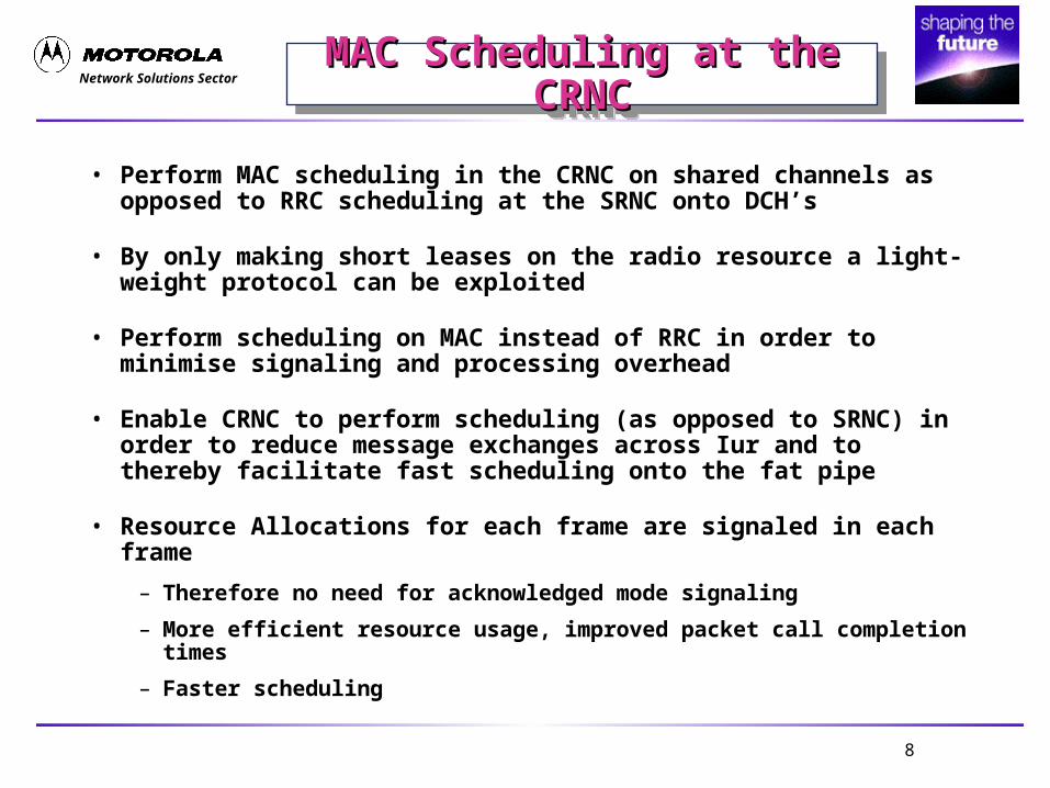
• Findings published in Motorola Contribution to SMG2 UMTS-L23 534/98 dated 12/9/98
• Preferable to allocate the total packet bandwidth allocation to a single user than to allocate an equal total packet bandwidth of multiple narrower band channels to simultaneous users.
Models for various services.
Service Sessionarrival
Ave # ofpkt callspersession
Avereadingtimebetweenpkt calls
Avenumber ofpkts in pktcall
Ave inter-arrivaltimebetweenpkts
Packetsizes
web Poisson 5[5] 120 sec[8] 25[5] 10 msec 480[5]
email Poisson 1 -- 15[9] 10 msec 158[9]

Network Solutions Sector
10
Benefits of Fat Pipe (cont’d)Benefits of Fat Pipe (cont’d)Benefits of Fat Pipe (cont’d)Benefits of Fat Pipe (cont’d)
Simulation results for single service (Email) implementation.
Number ofpacket
channels
Pkt ChBW
Kbps Percent load
AverageQueue delay
(seconds)
AverageTransmissiontime (second)
Total delaytime
(seconds)
1 307 75 0.24 0.049 0.289
8 38.6 75 0.088 0.39 0.478
16 19.2 75 0.05 0.788 0.838
Note: Total delay time in Table 1 and 2 refer to packet call completion time
Simulation results for single service (Web Browsing) implementation.
Web Browsing
Number ofpacket
channels
Pkt ChBW
KbpsPercent load
AverageQueue delay
(seconds)
AverageTransmissiontime (second)
Total delaytime
(seconds)
1 307 75 1.27 0.313 1.588 38.6 75 0.708 2.51 3.22
16 19.2 75 0.461 5.02 5.48

Network Solutions Sector
11
Overview of Downlink Shared Channel Overview of Downlink Shared Channel ((DSCHDSCH))
Overview of Downlink Shared Channel Overview of Downlink Shared Channel ((DSCHDSCH))
• Two methods for DSCH have been proposed
– DSCH with Time Multiplexed Packet Users (proposed by Lucent, Sony and Nortel, Tdoc SMG2 UMTS-L23 159/98, 320/98, 266/98, 169/98)
– DSCH with Fast Code Multiplexing (proposed by Nokia and Motorola, Tdoc SMG2 UMTS-L23 296/98, 533/98)
• It was agreed in SMG2 that DSCH should utilize Fast Code Multiplexing (FCM).
• Concept of DSCH included in ETSI’s document#XX03-130
• Two possibilities exists for carrying the control information for DSCH
– Using a dedicated channel (DCH)
– Using a common DSCH control channel (also called the ACCH)

Network Solutions Sector
12
DSCH with Fast Code MultiplexingDSCH with Fast Code MultiplexingDSCH with Fast Code MultiplexingDSCH with Fast Code Multiplexing
• Segment of the Code Tree for Orthogonal Variable Spread Factor (OVSF) codes assigned to packet data services
• The number of OVSF codes assigned for packet data services (and the number of UE’s served) can change on a frame by frame basis
1
2
3
4
5
6
7
8
9
10
11
12
13
14
15
16
17
1819202122
2324
2526
2728
2930
31
32 = No code
Tree AccessPoint
SF=8
SF=16
SF=32SF=64
SF=128
B ra n c h o f c o d e tre e a s s ig n e d top a c k e t d a ta s e rv ic e s .

Network Solutions Sector
13
Code Assignment for the DCHCode Assignment for the DCHCode Assignment for the DCHCode Assignment for the DCH
• A 384 kbps packet data service is assigned a SF = 8.
• Seven 384 Kbps UEs at activity rate of 1/10 consume 87% of OVSF tree.
SF=1
SF=2
SF=4
SF=8
SF=16SF=32

Network Solutions Sector
14
SF=64SF=128,256
SF=1
SF=2
SF=4
SF=8
SF=16SF=32
• All 384 kbps on the DSCH monitor the same ACCH at SF=64 and the SF=8 is assigned as needed.
• The same seven 384 kbps UEs at activity rate of 1/10 consume only 14% of OVSF tree.
Code Assignment for the DSCHCode Assignment for the DSCHCode Assignment for the DSCHCode Assignment for the DSCH

Network Solutions Sector
15
Signaling Options for DSCHSignaling Options for DSCHSignaling Options for DSCHSignaling Options for DSCH
• DSCH is associated with a DCH
– Disadvantages• Less powerful coding on allocation messages (e.g. (32,6) Bi-orthogonal
Code used for TFCI field)• Signaling resources consumed will be proportional to the number of users
• DSCH is associated with a common control channel called Access Control Channel (ACCH)
– Advantages• ACCH time multiplexes all assignments on a single, relatively low rate,
OVSF code, thus reducing the overall OVSF codes used for control• ACCH is always synchronized to the frame timing of the current cell
– Disadvantage• Fixed power allocation, does not use Fast Forward Power Control (FFPC)
– Simulations show that ACCH will be more efficient when resources are needed the most.

Network Solutions Sector
16
Probability of N or more Simultaneous Packet Calls(Web Browsing)
0%
10%
20%
30%
40%
50%
60%
70%
80%
90%
100%
0 10 20 30 40 50N
75%
90%
92%
95%
Common Channel more efficient
Dedicated Channel more efficient
DSCH control channel efficiencyDSCH control channel efficiency

Network Solutions Sector
17
Common Control Channel vs. Dedicated Common Control Channel vs. Dedicated Control Channel Control Channel
Common Control Channel vs. Dedicated Common Control Channel vs. Dedicated Control Channel Control Channel
• Summary
– For low channel utilization DCH is efficient
– For high channel utilization or when resources are needed most ACCH is more efficient
• Recommendation
– Provide both methods in the specification
Mean Simultaneous Users Likelihood a Common Channelwill be more Efficient
Shared ChannelUtilization
SessionArrival Rate
Analytic Simulated 10:1 20:1
95% 0.76 18.05 16.5 57% 34%
92% 0.72 10.58 10.9 42% 20%
90% 0.70 8.1 7.86 31% 10%
70% 0.60 2.25 2.19 7% 0.3%

Network Solutions Sector
18
Limitations of Packet Modeling Limitations of Packet Modeling TechniquesTechniques
Limitations of Packet Modeling Limitations of Packet Modeling TechniquesTechniques
• Number of simultaneous users is sensitive to packet interarrival time.
– Congestion elsewhere in the network may increase interarrival times
– Confidence in the data models is modest at best?• Will all applications fit into the narrow data models for ftp, www, and email?• What are the correct proportions?
• UMTS protocol must adapt to data traffic presented. A Common Control Channel makes no assumptions on data traffic patterns.
• Maximum packet size is governed by the IP Maximum Transmission Unit (MTU).
– Typical MTU is on the order of 500 bytes.
– 1500 bytes is the practical maximum for the MTU
– ETSI’s model specifies a maximum of 66,000 bytes
• The total data transfers sizes will not be known a priori. Therefore, the dedicated channel may not be as effective as previous simulations suggest.

Network Solutions Sector
19
Details of the Common Control Details of the Common Control Channel for DSCHChannel for DSCH
Details of the Common Control Details of the Common Control Channel for DSCHChannel for DSCH
• Common Control Channel for DSCH (Access Control Channel (ACCH))
– Aggregates functions of • Uplink Power Control• Dynamic Persistence for RACH• Downlink OVSF Code Assignment• Uplink SF Assignment • Uplink Timing Event
– ACCH provides a direct method for assigning resources of the shared channel
– ACCH is not power controlled
– ACCH is transmitted over the entire cell

Network Solutions Sector
20
Structure of the ACCHStructure of the ACCHStructure of the ACCHStructure of the ACCH
0.625 ms, 20*2k bits (k=0..6)
Slot #1 Slot #2 Slot #i Slot #16
Frame #1 Frame #2 Frame #i Frame #72
Tf = 10 ms
P ilo tT P C
# 0T P C
# 1T P C
# 2T P C
# 3T P C
# 4T P C
# 5T P C
# 6T P C
# 7 C o d e d A ss ig n m e n t In fo rm a tio n
N T P CN P ilo t N D a ta

Network Solutions Sector
21
ACCH Assignment FieldsACCH Assignment FieldsACCH Assignment FieldsACCH Assignment Fields
Uplink Shared Channel Assignment
Field Bits Reference
TUEID 8 A 8-bit temporary ID providing unique to particularcell
SFA 3 Assigns the spreading factor for the next frame.
PCPA 3 Assigns a position in the common power controlchannel for the duration of the transfer.
Total 14
Downlink Shared Channel Assignement
Field Bits Reference
TUEID 8 A 8-bit temporary ID providing unique to particularcell
OVSF CodeAssignment
7 Assigns a specific branch of the code tree.
Total 15

Network Solutions Sector
22
Number of Assignments per Frame for Number of Assignments per Frame for Various SF and Coding RatesVarious SF and Coding Rates
Number of Assignments per Frame for Number of Assignments per Frame for Various SF and Coding RatesVarious SF and Coding Rates
Spreading Factor
Npilot NTPC NdataFrame Period (ms)
Repitition Coding CRC TailInfo bits available
DPI DOCA/user UPA/user Users
256 8 8 4 10 1 1/3 16 8 -3 10 15 14 0128 8 8 24 10 3 1/3 16 8 103 10 15 14 364 8 8 64 10 1 1/3 16 8 317 10 15 14 10
128 8 8 24 10 0 1/2 16 8 168 10 15 14 5
• With a Spreading Factor of 128 and using R=1/2 Convolutional or Turbo Code, ACCH can accommodate assignments for 5 UE’s in both direction or assignments for 10 UE’s in one direction simultaneously per frame.

Network Solutions Sector
23
Overview of Uplink Shared Channel (USCH)Overview of Uplink Shared Channel (USCH)Overview of Uplink Shared Channel (USCH)Overview of Uplink Shared Channel (USCH)
• USCH represents a shared power resource
• USCH coordinates fast scheduling of uplink data packets
– Insure an uniform interference power profile protecting voice users
– Schedule “Budgeted Noise Rise”• Each active MS is assigned a fraction of total noise rise which translates to a
Spread Factor (SF) assignment• Reassign the data rate on a frame by frame basis (functionally equivalent to
downlink FCM)• UE synchronizes framing to the strongest BTS on the active set

Network Solutions Sector
24
USCH DetailsUSCH DetailsUSCH DetailsUSCH Details
• Commonality with DCH – Identical PDTCH channel frame formats– Ability to perform fast and slow power control– May employ soft handoff if necessary
• Differences from the DCH – Discontinuous uplink transmission requires a one frame preamble
before the start of data transmission.– Performance is identical to DCH when frames are consecutive– The preamble will prime acquisition, channel estimation and
power control.– Timing advance or guard band is required for large cell sizes
– Transmission from an near to BTS UE may overlap the transmission from a far from BTS UE, resulting in excessive noise rise.

Network Solutions Sector
25
Fast Power Control and Channel Fast Power Control and Channel Estimation for USCHEstimation for USCH
Fast Power Control and Channel Fast Power Control and Channel Estimation for USCHEstimation for USCH
• Convergence of power control loop and the availability of good channel estimates are critical for operation of USCH. Two solutions are envisaged
• Use of a low rate bi-directional link maintenance channel between packet burst
• Unnecessary power resource is consumed when there are no packets to transmit
• Increase in uplink noise rise• Maintaining a dedicated downlink channel for each uplink channel will
worsen the code shortage problem
– Preamble transmission using DPCCH before packet data transmission

Network Solutions Sector
26
Bi-directional Link Maintenance Channel Bi-directional Link Maintenance Channel Bi-directional Link Maintenance Channel Bi-directional Link Maintenance Channel
P R A C H
U S C H
D P C C H
A C C H
D S C H
Dow nlink PhysicalChannels
Uplink PhysicalChannels
10 m s

Network Solutions Sector
27
Preamble TransmissionPreamble TransmissionPreamble TransmissionPreamble Transmission
P R A C H
U S C H
D P C C H
A C C H
D S C H
Dow nlink PhysicalChannels
Uplink PhysicalChannels
10 m s
O pen Loop P ower E stim ate
Ideal Power Setting1dB
2 dB
X dB
Network Solutions Sector
28
Preamble Transmission (cont’d)Preamble Transmission (cont’d)Preamble Transmission (cont’d)Preamble Transmission (cont’d)
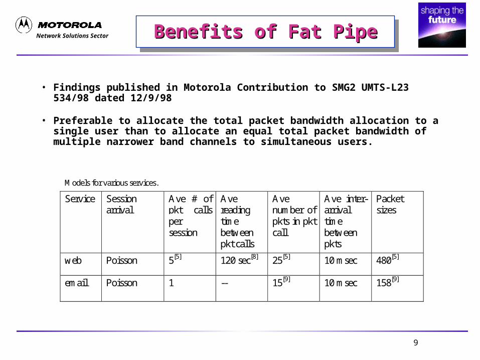
• Three cases are considered in the Figure
– No need for Preamble, if RACH is used before transmission of packets
– Preamble used to converge uplink DPCCH (for power control, channel estimation and acquisition), before packet data transmission starts on DSCH
– Preamble used to converge uplink DPCCH (for power control, channel estimation and acquisition), before packet data transmission starts on USCH

Network Solutions Sector
29
Preamble TransmissionPreamble TransmissionPreamble TransmissionPreamble Transmission
DPDCH
DPCCH
Cd
Cc
Cscramb
QPSK Modulation
j
Ad
Ap
Switched off during preamble transmission

Network Solutions Sector
30
Consecutive Idle Frames within a Packet Call Consecutive Idle Frames within a Packet Call for Various Values of System Utilizationfor Various Values of System Utilization
Consecutive Idle Frames within a Packet Call Consecutive Idle Frames within a Packet Call for Various Values of System Utilizationfor Various Values of System Utilization
Mean packet size = 480 bytes
Rate = 384 Kbps

Network Solutions Sector
31
Timing EventsTiming EventsTiming EventsTiming EventsTiming EventsTiming EventsTiming EventsTiming Events
• If a far-end UE and a near-end UE is assigned a low SF code in consecutive frames, the last part of transmission from far-end UE may collide with the first part of transmission from near-end UE (due to propagation delay) resulting in excessive noise-rise in the cell in question.
• UE’s need to retard their timing by an amount t to prevent collisions
• Three methods are proposed for computation of t:
– Method1 - t is computed based on a relative distance between the two UE’s w.r.t BTS
– Method2 - t is computed based on a distance between a single UE and the BTS
– Method 3 - Uses a fixed guard period

Network Solutions Sector
32
N o d e BU E C
U E B
U E A
U E A T ran sm it T im in g
U E B T ran sm it T im in g
U E C T ran sm it T im in g
UE’s Propagation Delay w/o Timing Offset UE’s Propagation Delay w/o Timing Offset CorrectionCorrection
UE’s Propagation Delay w/o Timing Offset UE’s Propagation Delay w/o Timing Offset CorrectionCorrection
• is proportional to the range between the node B and UE#A
• is proportional to the range between the node B and UE#B
• is proportional to the range between the node B and UE#C

Network Solutions Sector
33
Signaling Methods for Timing EventsSignaling Methods for Timing EventsSignaling Methods for Timing EventsSignaling Methods for Timing Events
U E B
U E C
A C C H
U E A
Uplink SharedChannel
10 m s
F ra m e # 1 F ra m e # 2 F ra m e # 3 F ra m e # 4 F ra m e # 5 F ra m e # 6 F ra m e # 7 F ra m e # 8 F ra m e # 9
t1
t2
t3
t4 t5
t6
t7 t8 t9
• Method - 1
– TOA from UE#A to node-B -
– TOA from UE#B to node-B -
– UE#B retards its frame timing by an amount t2 =
Network Solutions Sector
34
Signaling Methods for Timing Events Signaling Methods for Timing Events (cont’d)(cont’d)
Signaling Methods for Timing Events Signaling Methods for Timing Events (cont’d)(cont’d)
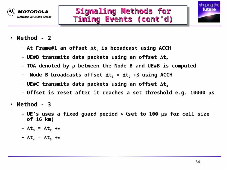
• Method - 2
– At Frame#1 an offset t2 is broadcast using ACCH
– UE#B transmits data packets using an offset t2
– TOA denoted by between the Node B and UE#B is computed
– Node B broadcasts offset t3 = t2 using ACCH
– UE#C transmits data packets using an offset t3
– Offset is reset after it reaches a set threshold e.g. 10000 s
• Method - 3
– UE’s uses a fixed guard period set to 100 s for cell size of 16 km)
– t3 = t2
– t4 = t3

Network Solutions Sector
35
QoS for W-CDMA PacketQoS for W-CDMA PacketQoS for W-CDMA PacketQoS for W-CDMA Packet
• Base QoS on network and application standards
– Internet QoS (End-to-end QoS support)• Guaranteed throughput and bounded delays• FER is irrelevant for most or manydata services, networks are effectively
perfect. However, delay is related to operating FER.
– QoS negotiation (analogous to call set-up)• Admission control for premium service levels• At L2 & MAC each mobile has QoS associated
• Implications for the MAC scheduling
– Need to signal multiple queue depths (per QoS level) during RACH
– Scheduling based QoS level
– May police mobiles with respect to negotiated QoS.
– Must standardize method for representing mobile QoS with UTRAN.
Network Solutions Sector
36
ConclusionsConclusionsConclusionsConclusions
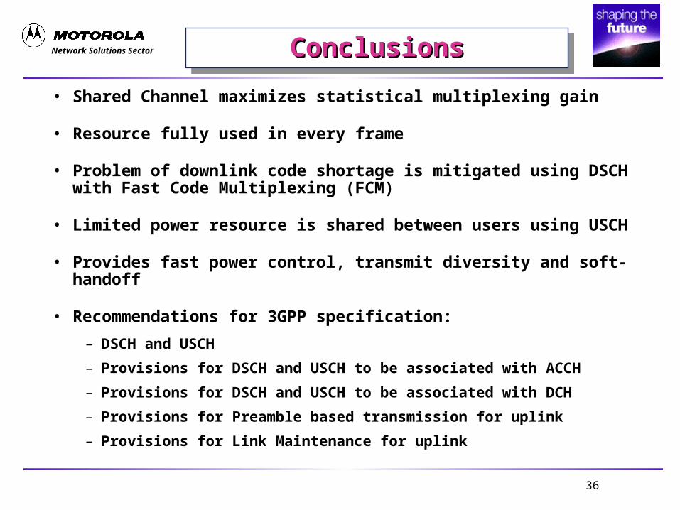
• Shared Channel maximizes statistical multiplexing gain
• Resource fully used in every frame
• Problem of downlink code shortage is mitigated using DSCH with Fast Code Multiplexing (FCM)
• Limited power resource is shared between users using USCH
• Provides fast power control, transmit diversity and soft-handoff
• Recommendations for 3GPP specification:
– DSCH and USCH
– Provisions for DSCH and USCH to be associated with ACCH
– Provisions for DSCH and USCH to be associated with DCH
– Provisions for Preamble based transmission for uplink
– Provisions for Link Maintenance for uplink


![Random Packet-CDMA: Reducing Delay and Increasing ...rolke/content/Kempter-SDR2006.pdf · RP-CDMA packet structure [KemAmiFar06, SchKemKot06] [KemAmiFar06] R. Kempter, P. Amini and](https://img.pdfslide.us/doc/110x75/5fc43e1f618f14339211c1c9/random-packet-cdma-reducing-delay-and-increasing-rolkecontentkempter-.jpg)