Embed Size (px)
Citation preview
Network Service Chaining Solutions
Santanu Dasgupta, Consulting Systems Engineer
BRKRST-2319
Vaughn Suazo, Distinguished Systems Engineer
• Introduction
• Service Chaining – Why and What ?
• Service Chaining – Use Cases
• Service Chaining Technologies
• Service Chaining Rationalization
• Conclusion
Agenda
Session Pre-Requisites
• Understanding of Routing and Switching Technologies
• Understanding of the basic concepts around Software Defined Networking (SDN) and Network Functions Virtualization (NFV)
• Understanding of IP Overlay technologies is a plus!
What We are Not Going to Cover in this Session?
• Topics on Service Chaining such as –
• Load balancing
• Service Chaining HA
• Service Chaining scenarios that includes “Applications” as the Service Function
• Workload Placement and Related Optimization for Service Chain setup
• The session will mostly focus on why service chaining is important and how do we rationalize
Service Chaining Why & What ?
What is a “Service or Service Function (SF)” ?
• Could be of many types, many different perspectives –• Network functions helping provide connectivity
• Security functions
• Vertical services such as Finance, Sales or HR application
• Something that provides compute or storage resource
• …..
• Services are built to satisfy business needs
• It must adhere to policies that define operational characteristics and access controls
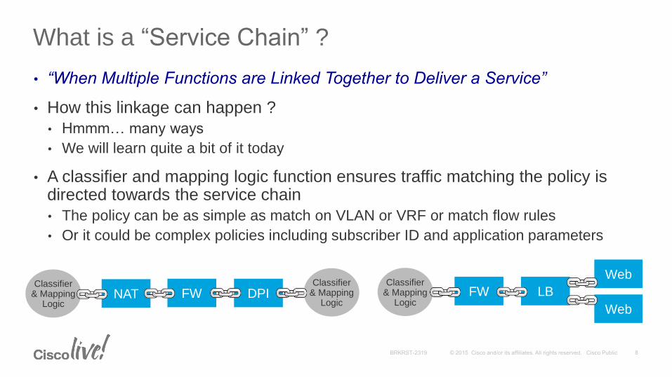
What is a “Service Chain” ?
• “When Multiple Functions are Linked Together to Deliver a Service”
• How this linkage can happen ?
• Hmmm… many ways
• We will learn quite a bit of it today
• A classifier and mapping logic function ensures traffic matching the policy is directed towards the service chain
• The policy can be as simple as match on VLAN or VRF or match flow rules
• Or it could be complex policies including subscriber ID and application parameters
NAT FW DPI FW LB
Web
Web
Classifier & Mapping
Logic
Classifier & Mapping
Logic
Classifier & Mapping
Logic
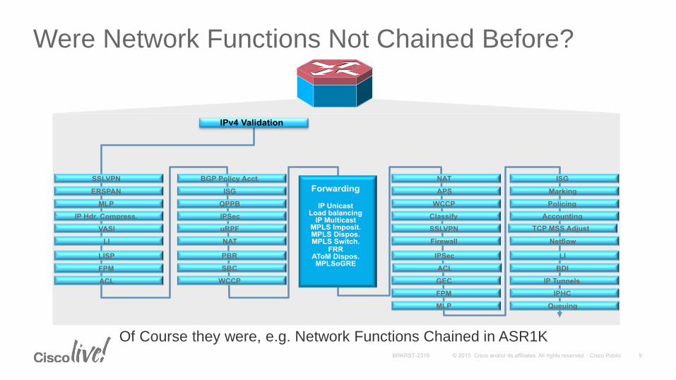
Were Network Functions Not Chained Before?
IPv4 Validation
SSLVPN
ERSPAN
MLP
IP Hdr. Compress.
VASI
LI
LISP
FPM
ACL
BGP Policy Acct.
ISG
QPPB
IPSec
uRPF
NAT
PBR
SBC
WCCP
ISG
Marking
Policing
Accounting
TCP MSS Adjust
Netflow
LI
BDI
IP Tunnels
NAT
APS
WCCP
Classify
SSLVPN
Firewall
IPSec
ACL
GEC
FPM
MLP
IPHC
Queuing
Forwarding
IP Unicast
Load balancing IP Multicast
MPLS Imposit. MPLS Dispos. MPLS Switch.
FRR AToM Dispos. MPLSoGRE
Of Course they were, e.g. Network Functions Chained in ASR1K
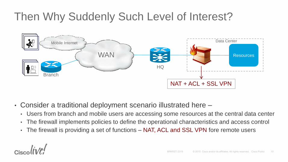
Then Why Suddenly Such Level of Interest?
Resources
NAT + ACL + SSL VPN
WAN
Branch
HQ
Data Center
• Consider a traditional deployment scenario illustrated here –• Users from branch and mobile users are accessing some resources at the central data center
• The firewall implements policies to define the operational characteristics and access control
• The firewall is providing a set of functions – NAT, ACL and SSL VPN fore remote users
Mobile Internet
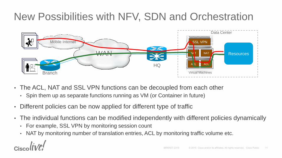
New Possibilities with NFV, SDN and Orchestration
ResourcesWAN
Branch
HQ
Data Center
Mobile Internet SSL VPN
NAT
ACL
Virtual Machines
NAT NAT
ACL ACL
• The ACL, NAT and SSL VPN functions can be decoupled from each other
• Spin them up as separate functions running as VM (or Container in future)
• Different policies can be now applied for different type of traffic
• The individual functions can be modified independently with different policies dynamically
• For example, SSL VPN by monitoring session count
• NAT by monitoring number of translation entries, ACL by monitoring traffic volume etc.
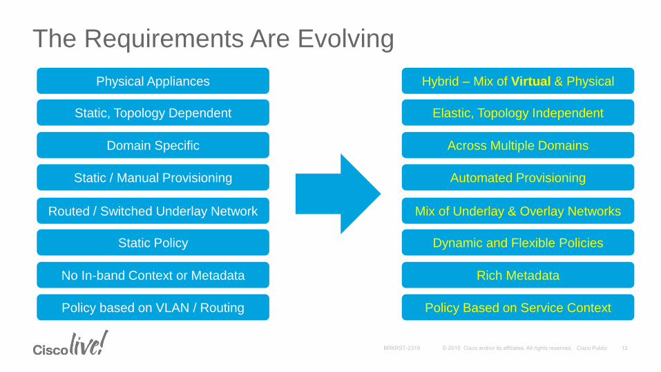
The Requirements Are Evolving
Physical Appliances
Static, Topology Dependent
Domain Specific
Static / Manual Provisioning
Routed / Switched Underlay Network
Static Policy
No In-band Context or Metadata
Policy based on VLAN / Routing
Hybrid – Mix of Virtual & Physical
Elastic, Topology Independent
Across Multiple Domains
Automated Provisioning
Mix of Underlay & Overlay Networks
Dynamic and Flexible Policies
Rich Metadata
Policy Based on Service Context
Service Chaining Use Cases
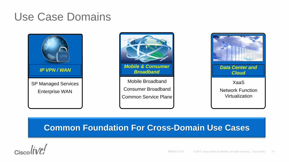
Mobile & Consumer Broadband
Mobile Broadband
Consumer Broadband
Common Service Plane
XaaS
Network Function
Virtualization
Data Center and Cloud
IP VPN / WAN
SP Managed Services
Enterprise WAN
Use Case Domains
Common Foundation For Cross-Domain Use Cases

CPE
Cust-A
CPE
Cust-A
CPE
Cust-A
IP Network
Internet
CPE
Cust-B
CPE
Cust-B
DCI
IGW
Orchestration
vFWvRouter WSA
vFWVRvRouter vFW
CloudVPN with Internet Based Last Mile Connectivity
• The CPE to CloudVPN connectivity
is via Internet need to use a
secure overlay connectivity model
• The service functions are for this
use case are typically networking
and security functions
• Different service chains can be set
up to meet end-user requirements
• The service policy ensures that
traffic from the branches gets
forwarded via the service chain
before it is routed to the Internet
IP VPN / WAN
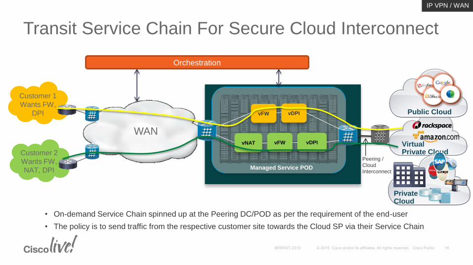
Customer 1
Wants FW,
DPI
Customer 2
Wants FW,
NAT, DPI
WAN
Peering /
Cloud
InterconnectManaged Service POD
vNAT vDPI
Transit Service Chain For Secure Cloud Interconnect
VirtualPrivate Cloud
PrivateCloud
Public Cloud
Orchestration
• On-demand Service Chain spinned up at the Peering DC/POD as per the requirement of the end-user
• The policy is to send traffic from the respective customer site towards the Cloud SP via their Service Chain
vFW
vFW vDPI
IP VPN / WAN
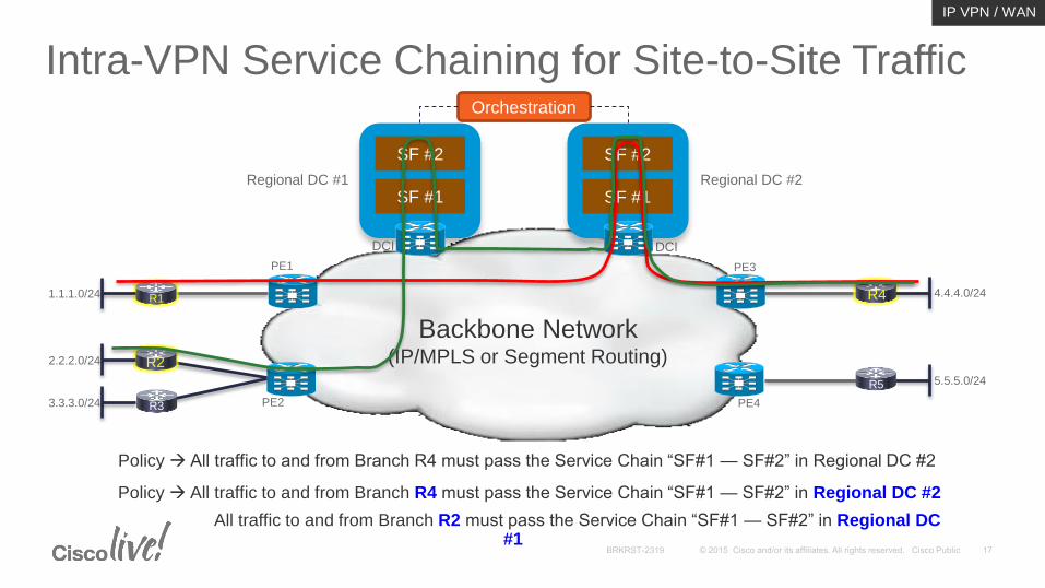
Intra-VPN Service Chaining for Site-to-Site Traffic
R1
R2
R3
R4
R5
PE1
PE2
PE3
PE4
Backbone Network(IP/MPLS or Segment Routing)
1.1.1.0/24
2.2.2.0/24
3.3.3.0/24
4.4.4.0/24
5.5.5.0/24
DCI DCI
SF #1
SF #2
SF #1
SF #2
Orchestration
Regional DC #1 Regional DC #2
Policy All traffic to and from Branch R4 must pass the Service Chain “SF#1 — SF#2” in Regional DC #2
IP VPN / WAN
Policy All traffic to and from Branch R4 must pass the Service Chain “SF#1 — SF#2” in Regional DC #2
All traffic to and from Branch R2 must pass the Service Chain “SF#1 — SF#2” in Regional DC #1
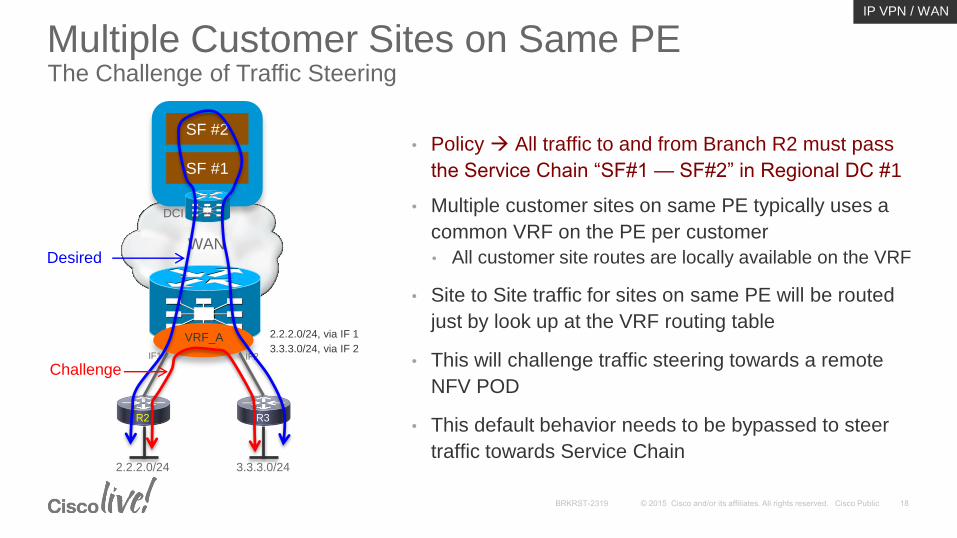
Multiple Customer Sites on Same PEThe Challenge of Traffic Steering
• Policy All traffic to and from Branch R2 must pass
the Service Chain “SF#1 — SF#2” in Regional DC #1
• Multiple customer sites on same PE typically uses a
common VRF on the PE per customer
• All customer site routes are locally available on the VRF
• Site to Site traffic for sites on same PE will be routed
just by look up at the VRF routing table
• This will challenge traffic steering towards a remote
NFV POD
• This default behavior needs to be bypassed to steer
traffic towards Service Chain
R2 R3
2.2.2.0/24 3.3.3.0/24
VRF_A3.3.3.0/24, via IF 2
2.2.2.0/24, via IF 1
IF1 IF2
DCI
SF #1
SF #2
WAN
IP VPN / WAN
Desired
Challenge
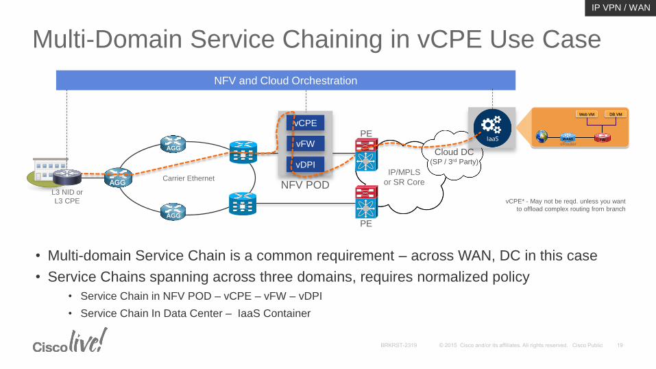
Multi-Domain Service Chaining in vCPE Use Case
Carrier EthernetAGG
AGG
AGG
NPE
NPE
IP/MPLS
or SR Core
vFW
vCPE
vDPI
NFV POD
NFV and Cloud Orchestration
Cloud DC(SP / 3rd Party)
PE
PE
L3 NID or
L3 CPE
Web VM DB VM
FW WAAS
vCPE* - May not be reqd. unless you want
to offload complex routing from branch
• Multi-domain Service Chain is a common requirement – across WAN, DC in this case
• Service Chains spanning across three domains, requires normalized policy
• Service Chain in NFV POD – vCPE – vFW – vDPI
• Service Chain In Data Center – IaaS Container
vRouter
IP VPN / WAN
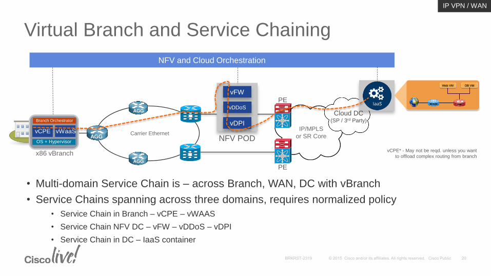
Virtual Branch and Service Chaining
Carrier EthernetAGG
AGG
AGG
NPE
NPE
IP/MPLS
or SR Core
vDDoS
vFW
vDPI
NFV POD
NFV and Cloud Orchestration
Cloud DC(SP / 3rd Party)
PE
PE
x86 vBranch
Web VM DB VM
FW WAAS
vCPE* - May not be reqd. unless you want
to offload complex routing from branch
OS + Hypervisor
Branch Orchestrator
vWaaSvCPE
• Multi-domain Service Chain is – across Branch, WAN, DC with vBranch
• Service Chains spanning across three domains, requires normalized policy
• Service Chain in Branch – vCPE – vWAAS
• Service Chain NFV DC – vFW – vDDoS – vDPI
• Service Chain in DC – IaaS container
IP VPN / WAN
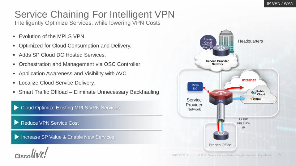
Service Chaining For Intelligent VPNIntelligently Optimize Services, while lowering VPN Costs
Evolution of the MPLS VPN.
Optimized for Cloud Consumption and Delivery.
Adds SP Cloud DC Hosted Services.
Orchestration and Management via OSC Controller
Application Awareness and Visibility with AVC.
Localize Cloud Service Delivery.
Smart Traffic Offload – Eliminate Unnecessary Backhauling
Reduce VPN Service Cost
Increase SP Value & Enable New Services
Cloud Optimize Existing MPLS VPN Services
Internet
Branch Office
Service Provider Network
PublicCloud
PrivateCloud
Service Provider Network
Headquarters
MPLS VPN
PE
L2 PtP
MPLS PW
IP
Micro
DC
IP VPN / WAN
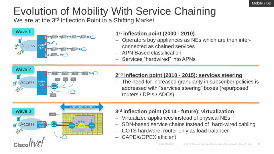
Evolution of Mobility With Service Chaining We are at the 3rd Inflection Point in a Shifting Market
Wave 1 1st inflection point (2000 - 2010)
Operators buy appliances as NEs which are then inter-
connected as chained services
APN Based classification
Services “hardwired” into APNs
Access GGSN/PGW
12ABC
3DEF
4GHI
5JKL
6MNO
7
PQRS
8TUV
9
WXYZ
*0#
Signal Strength
DPI
AP
N DPIDPI DPIL7 AF DPINATFW
AP
N
DPI L7 AF FW
PCRF
Wave 2
2nd inflection point (2010 - 2015): services steering
The need for increased granularity in subscriber policies is
addressed with “services steering” boxes (repurposed
routers / DPIs / ADCs)
Cloud orchestration
Access GGSN/PGW
12ABC
3DEF
4GHI
5JKL
6MNO
7
PQRS
8TUV
9
WXYZ
*0#
Signal Strength
AP
N
PCRF
Slice
SDNClassifier Classifier
Wave 3 3rd inflection point (2014 - future): virtualization
Virtualized appliances instead of physical NEs
SDN-based service chains instead of hard-wired cabling
COTS hardware; router only as load balancer
CAPEX/OPEX efficient
Mobile / BB
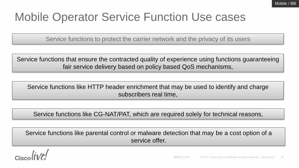
Mobile Operator Service Function Use cases
Service functions to protect the carrier network and the privacy of its users
Service functions that ensure the contracted quality of experience using functions guaranteeing
fair service delivery based on policy based QoS mechanisms,
Service functions like HTTP header enrichment that may be used to identify and charge
subscribers real time,
Service functions like CG-NAT/PAT, which are required solely for technical reasons,
Service functions like parental control or malware detection that may be a cost option of a
service offer.
Mobile / BB
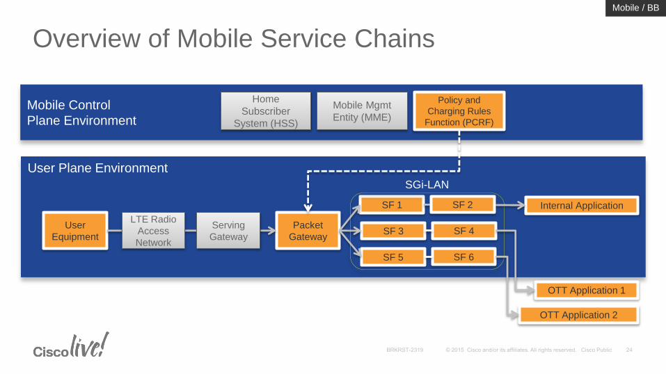
Overview of Mobile Service Chains
Mobile Control
Plane Environment
Home
Subscriber
System (HSS)
Mobile Mgmt
Entity (MME)
Policy and
Charging Rules
Function (PCRF)
User Plane Environment
User
Equipment
Packet
Gateway
LTE Radio
Access
Network
Serving
Gateway
SF 1
SF 3 SF 4
SF 5 SF 6
SGi-LAN
Internal Application
OTT Application 1
OTT Application 2
SF 2
Mobile / BB
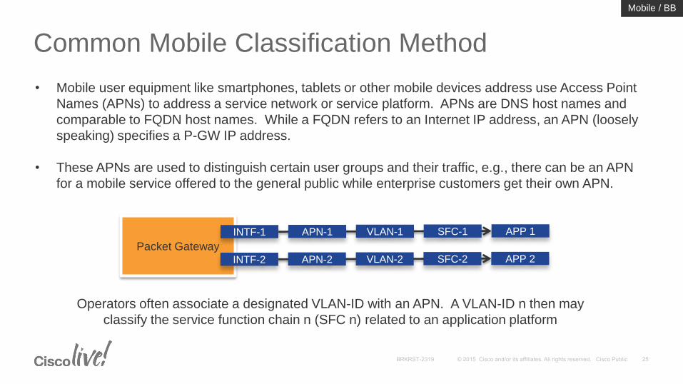
Common Mobile Classification Method
• Mobile user equipment like smartphones, tablets or other mobile devices address use Access Point
Names (APNs) to address a service network or service platform. APNs are DNS host names and
comparable to FQDN host names. While a FQDN refers to an Internet IP address, an APN (loosely
speaking) specifies a P-GW IP address.
• These APNs are used to distinguish certain user groups and their traffic, e.g., there can be an APN
for a mobile service offered to the general public while enterprise customers get their own APN.
Packet Gateway
INTF-1
INTF-2
APP 1
APP 2
APN-1 VLAN-1 SFC-1
APN-2 VLAN-2 SFC-2
Operators often associate a designated VLAN-ID with an APN. A VLAN-ID n then may
classify the service function chain n (SFC n) related to an application platform
Mobile / BB
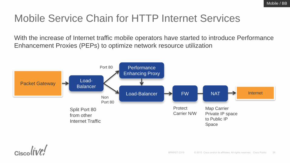
Mobile Service Chain for HTTP Internet Services
Packet Gateway
Performance
Enhancing Proxy
Load-Balancer FW Internet
Load-
Balancer
NAT
Port 80
Non
Port 80
With the increase of Internet traffic mobile operators have started to introduce Performance
Enhancement Proxies (PEPs) to optimize network resource utilization
Split Port 80
from other
Internet Traffic
Protect
Carrier N/WMap Carrier
Private IP space
to Public IP
Space
Mobile / BB
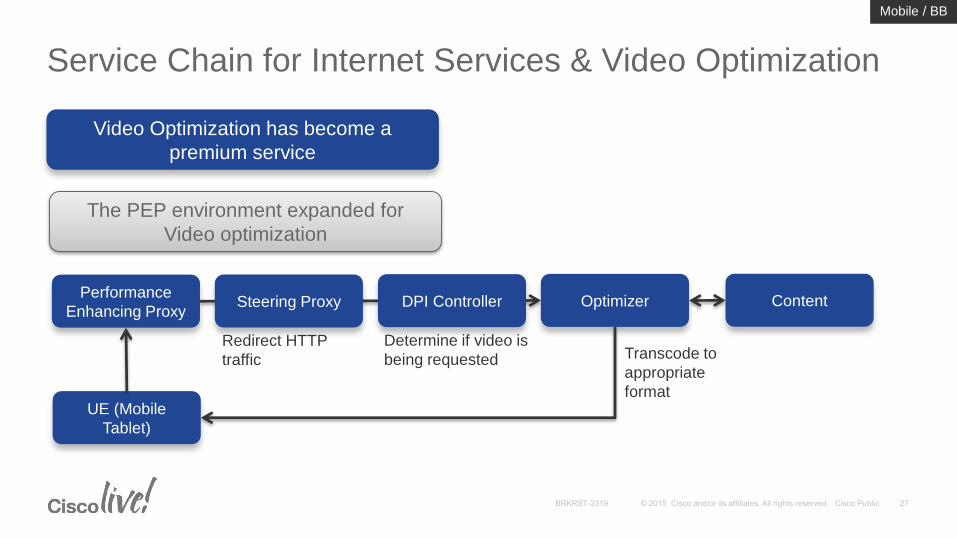
Service Chain for Internet Services & Video Optimization
Video Optimization has become a
premium service
The PEP environment expanded for
Video optimization
Performance
Enhancing Proxy
Redirect HTTP
traffic
Determine if video is
being requested Transcode to
appropriate
format
Steering Proxy DPI Controller ContentOptimizer
UE (Mobile
Tablet)
Mobile / BB
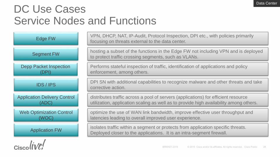
DC Use CasesService Nodes and Functions
Edge FW
Segment FW
IDS / IPS
Application Delivery Control
(ADC)
Web Optimization Control
(WOC)
Depp Packet Inspection
(DPI)
Performs stateful inspection of traffic, identification of applications and policy
enforcement, among others.
DPI SN with additional capabilities to recognize malware and other threats and take
corrective action.
VPN, DHCP, NAT, IP-Audit, Protocol Inspection, DPI etc., with policies primarily
focusing on threats external to the data center.
hosting a subset of the functions in the Edge FW not including VPN and is deployed
to protect traffic crossing segments, such as VLANs.
distributes traffic across a pool of servers (applications) for efficient resource
utilization, application scaling as well as to provide high availability among others.
Application FWisolates traffic within a segment or protects from application specific threats.
Deployed closer to the applications. It is an intra-segment firewall.
optimize the use of WAN link bandwidth, improve effective user throughput and
latencies leading to overall improved user experience.
Data Center
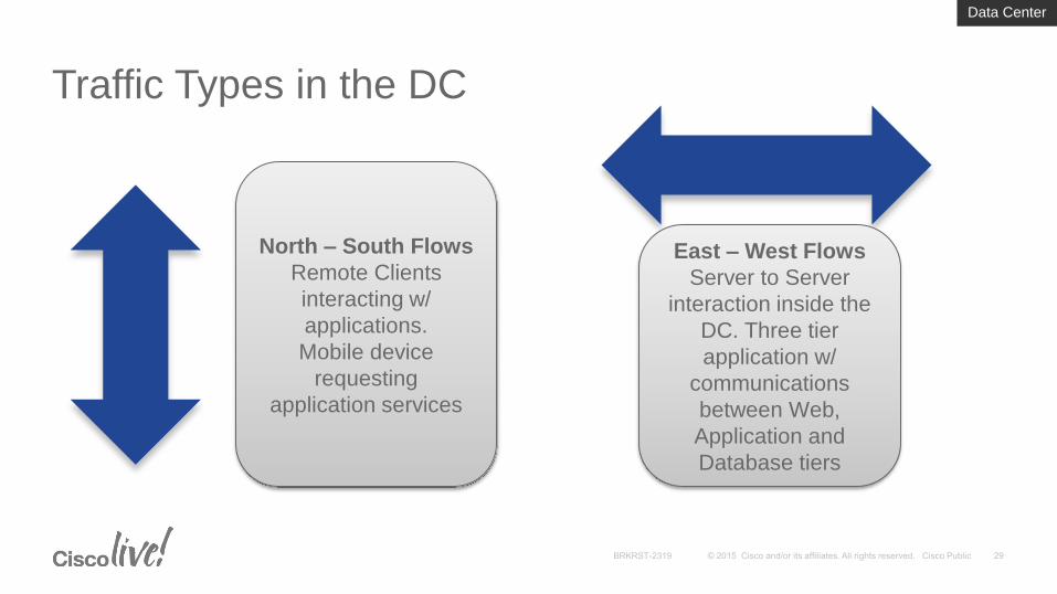
Traffic Types in the DC
North – South Flows
Remote Clients
interacting w/
applications.
Mobile device
requesting
application services
East – West Flows
Server to Server
interaction inside the
DC. Three tier
application w/
communications
between Web,
Application and
Database tiers
Data Center
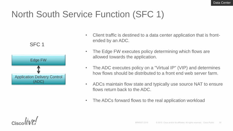
North South Service Function (SFC 1)
Edge FW
Application Delivery Control
(ADC)
SFC 1
• Client traffic is destined to a data center application that is front-
ended by an ADC.
• The Edge FW executes policy determining which flows are
allowed towards the application.
• The ADC executes policy on a "Virtual IP" (VIP) and determines
how flows should be distributed to a front end web server farm.
• ADCs maintain flow state and typically use source NAT to ensure
flows return back to the ADC.
• The ADCs forward flows to the real application workload
Data Center
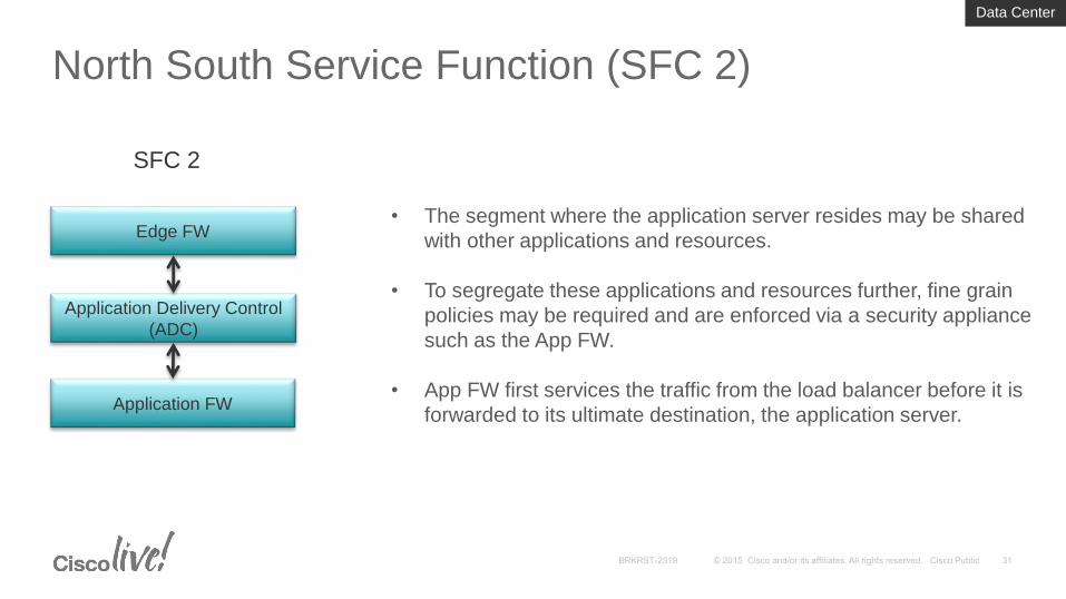
North South Service Function (SFC 2)
• The segment where the application server resides may be shared
with other applications and resources.
• To segregate these applications and resources further, fine grain
policies may be required and are enforced via a security appliance
such as the App FW.
• App FW first services the traffic from the load balancer before it is
forwarded to its ultimate destination, the application server.Application FW
Edge FW
Application Delivery Control
(ADC)
SFC 2
Data Center
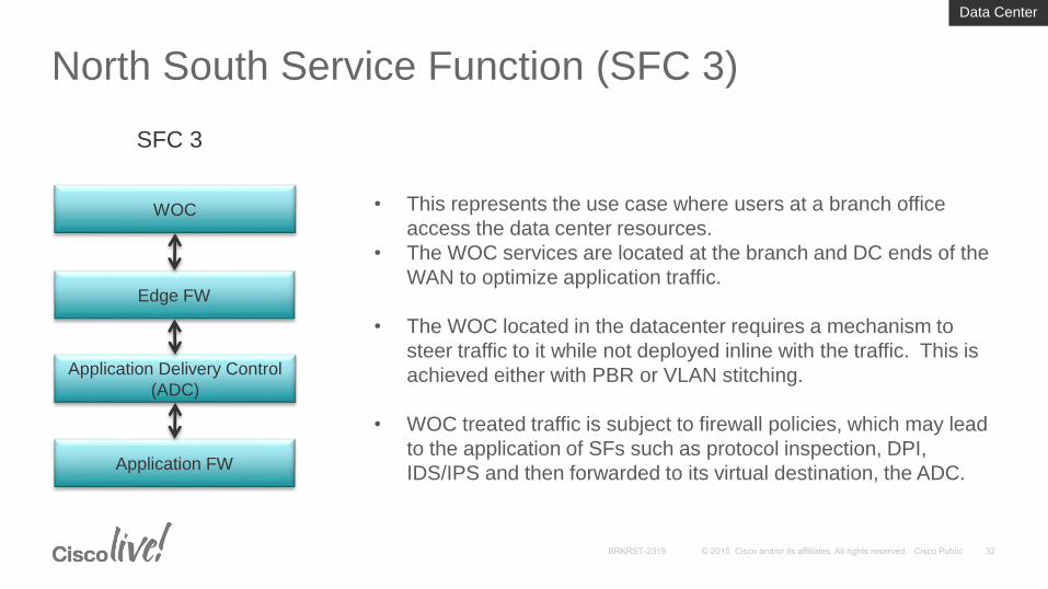
North South Service Function (SFC 3)
• This represents the use case where users at a branch office
access the data center resources.
• The WOC services are located at the branch and DC ends of the
WAN to optimize application traffic.
• The WOC located in the datacenter requires a mechanism to
steer traffic to it while not deployed inline with the traffic. This is
achieved either with PBR or VLAN stitching.
• WOC treated traffic is subject to firewall policies, which may lead
to the application of SFs such as protocol inspection, DPI,
IDS/IPS and then forwarded to its virtual destination, the ADC.
Edge FW
WOC
Application Delivery Control
(ADC)
Application FW
SFC 3
Data Center
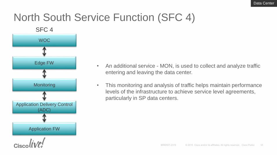
North South Service Function (SFC 4)
• An additional service - MON, is used to collect and analyze traffic
entering and leaving the data center.
• This monitoring and analysis of traffic helps maintain performance
levels of the infrastructure to achieve service level agreements,
particularly in SP data centers.
Edge FW
WOC
Monitoring
Application Delivery Control
(ADC)
SFC 4
Application FW
Data Center
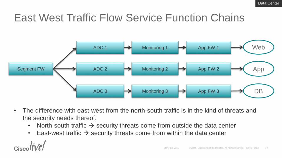
East West Traffic Flow Service Function Chains
Segment FW
ADC 1
ADC 2
ADC 3
Monitoring 1 App FW 1
Monitoring 2
Monitoring 3
App FW 2
App FW 3
Web
App
DB
• The difference with east-west from the north-south traffic is in the kind of threats and
the security needs thereof.
• North-south traffic security threats come from outside the data center
• East-west traffic security threats come from within the data center
Data Center
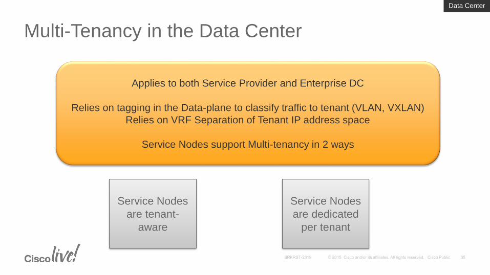
Multi-Tenancy in the Data Center
Applies to both Service Provider and Enterprise DC
Relies on tagging in the Data-plane to classify traffic to tenant (VLAN, VXLAN)
Relies on VRF Separation of Tenant IP address space
Service Nodes support Multi-tenancy in 2 ways
Service Nodes
are tenant-
aware
Service Nodes
are dedicated
per tenant
Data Center
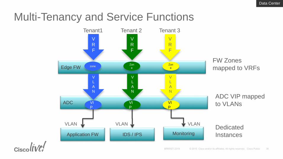
Multi-Tenancy and Service Functions
Edge FW
V
R
F
V
R
F
V
R
F
ADC
Tenant1 Tenant 2 Tenant 3
V
L
A
N
V
L
A
N
V
L
A
N
zoneZon
e
Zon
e
FW Zones
mapped to VRFs
ADC VIP mapped
to VLANsVI
P
VI
P
VI
P
Application FW IDS / IPS Monitoring
VLAN VLAN VLANDedicated
Instances
Data Center
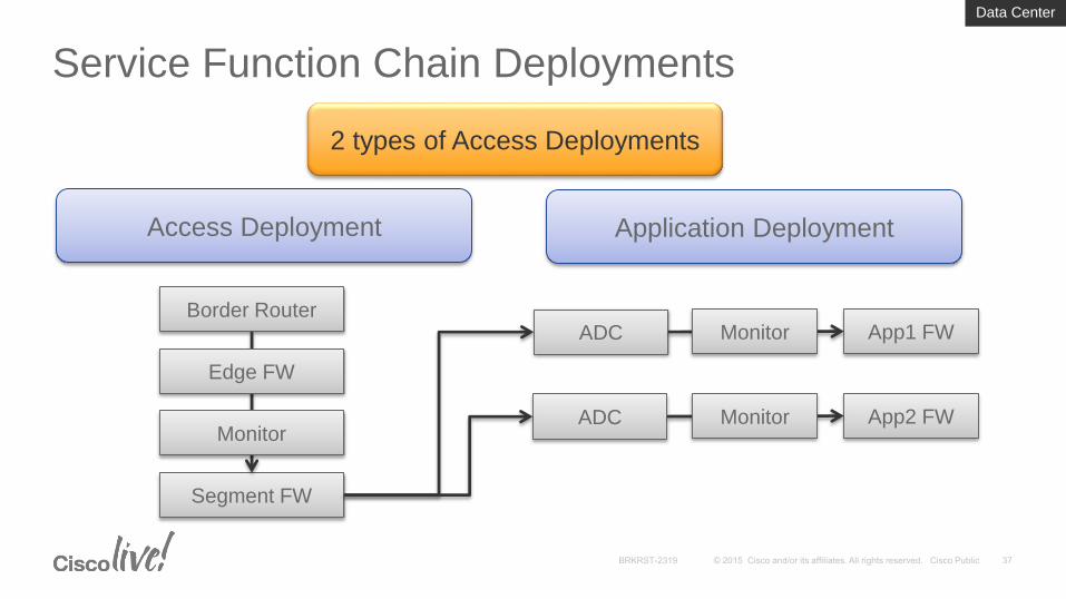
Service Function Chain Deployments
2 types of Access Deployments
Access Deployment Application Deployment
Border Router
Segment FW
Edge FW
Monitor
ADC App1 FWMonitor
ADC App2 FWMonitor
Data Center
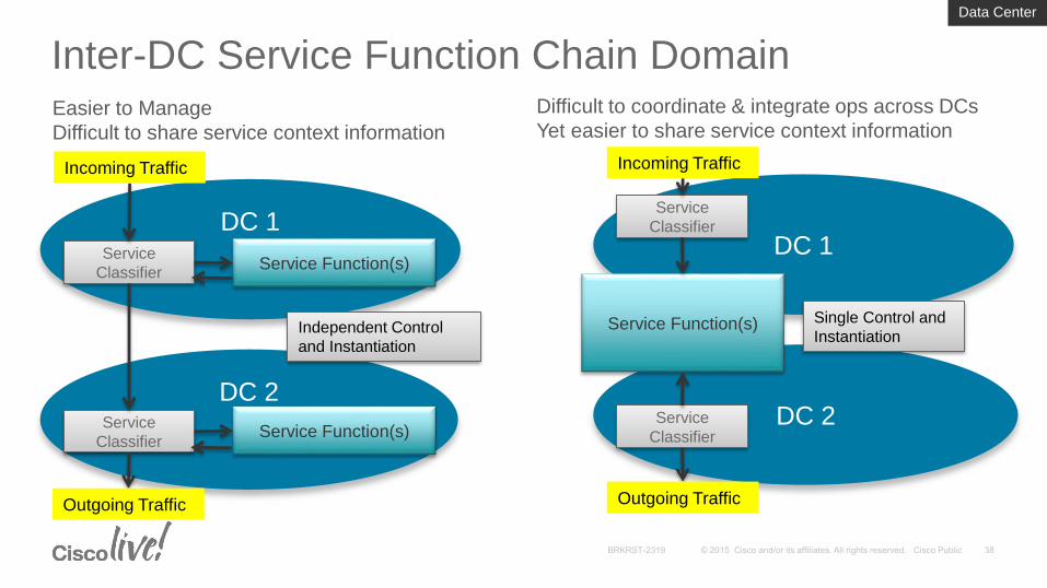
Inter-DC Service Function Chain Domain
DC 1
DC 2
Service
ClassifierService Function(s)
Service
ClassifierService Function(s)
Incoming Traffic
Outgoing Traffic
Independent Control
and Instantiation
DC 1
DC 2
Service
Classifier
Service Function(s)
Service
Classifier
Incoming Traffic
Outgoing Traffic
Difficult to coordinate & integrate ops across DCs
Yet easier to share service context information
Single Control and
Instantiation
Easier to Manage
Difficult to share service context information
Data Center

Service Chaining Technologies
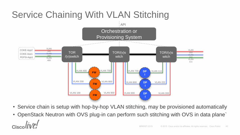
Service Chaining With VLAN Stitching
TOR
/(v)switch
FW
VLAN
200VLAN
400
COKE-App1
PEPSI-App1
COKE-App2VLAN
100
FW
FW
VLAN 400
VLAN 100
VLAN 200
VLAN 700
VLAN 900
VLAN 800 DP
I
DP
I
DP
I
VLAN 700
VLAN 900
VLAN 800
VLAN 111
VLAN 333
VLAN 222
VLAN
222VLAN
111
VLAN
333
Orchestration or
Provisioning System
API
TOR/(v)s
witch
• Service chain is setup with hop-by-hop VLAN stitching, may be provisioned automatically
• OpenStack Neutron with OVS plug-in can perform such stitching with OVS in data plane`
TOR/(v)s
witch
Server 1
VM1 VM1
VTF L2/L3 VRF FIB
L3 L2
Data Center Switching Infrastructure (Underlay Network)
DCI
Cisco VTS(Active)
Data Center Switching Infrastructure (Underlay Network)
Cisco VTS(Standby)
Cisco VTS Cisco VTS
DCI
Server 2
Server-2 VM2 VM2
VTF L2/L3 VRF FIB
L3 L2
Bare Metal Appliance
Bare Metal Server
ToR
Server 1
VM3 VM3
VTF L2/L3 VRF FIB
L3 L2
Server 2
Server-2 VM4 VM4
VTF L2/L3 VRF FIB
L3 L2
Server 1
Server-2 VM5 VM5
VTF L2/L3 VRF FIB
L3 L2
Purple
Green
Purple
Green
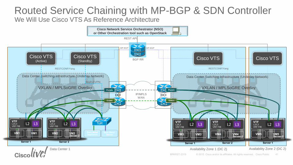
RESTCONF/Yang RESTCONF/Yang
MP-BGP MP-BGP
BGP RR
Cisco Network Service Orchestrator (NSO)
or Other Orchestration tool such as OpenStack
REST API
Data Center 1 Availability Zone 1 (DC 2) Availability Zone 2 (DC 2)
VXLAN / MPLSoGRE Overlay VXLAN / MPLSoGRE Overlay
IP/MPLS
WAN
Routed Service Chaining with MP-BGP & SDN ControllerWe Will Use Cisco VTS As Reference Architecture
BGP-EVPN
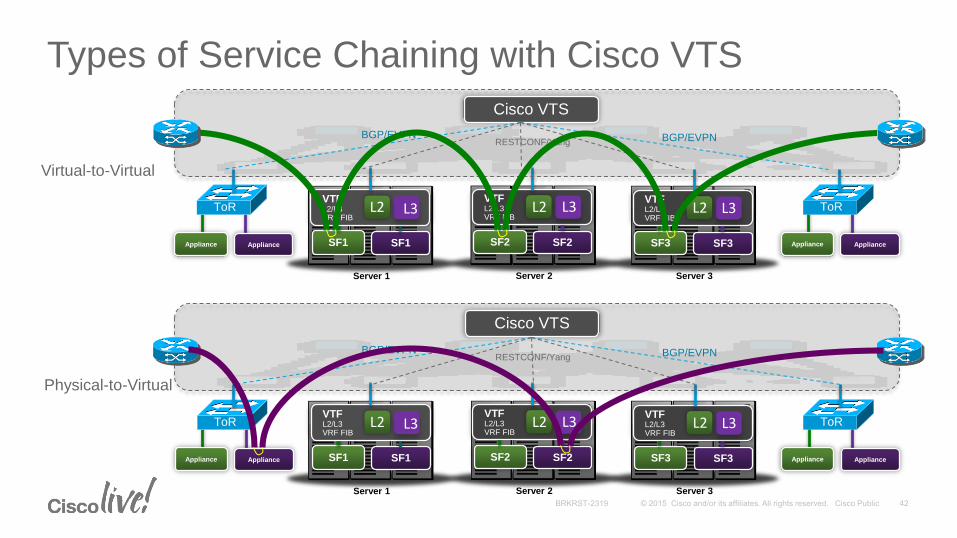
Types of Service Chaining with Cisco VTS
Server 1 Server 3Server 2
Server-2SF3 SF3
VTFL2/L3VRF FIB
L3
SF2 SF2
VTFL2/L3VRF FIB
L3
SF1 SF1
VTFL2/L3VRF FIB
L3
Appliance Appliance
ToRL2 L2 L2
Appliance Appliance
ToR
Server 1 Server 3Server 2
Server-2SF3 SF3
VTFL2/L3VRF FIB
L3
SF2 SF2
VTFL2/L3VRF FIB
L3
SF1 SF1
VTFL2/L3VRF FIB
L3
Appliance Appliance
ToRL2 L2 L2
Appliance Appliance
ToR
Cisco VTS
Cisco VTS
RESTCONF/Yang BGP/EVPNBGP/EVPN
RESTCONF/Yang BGP/EVPNBGP/EVPN
Virtual-to-Virtual
Physical-to-Virtual
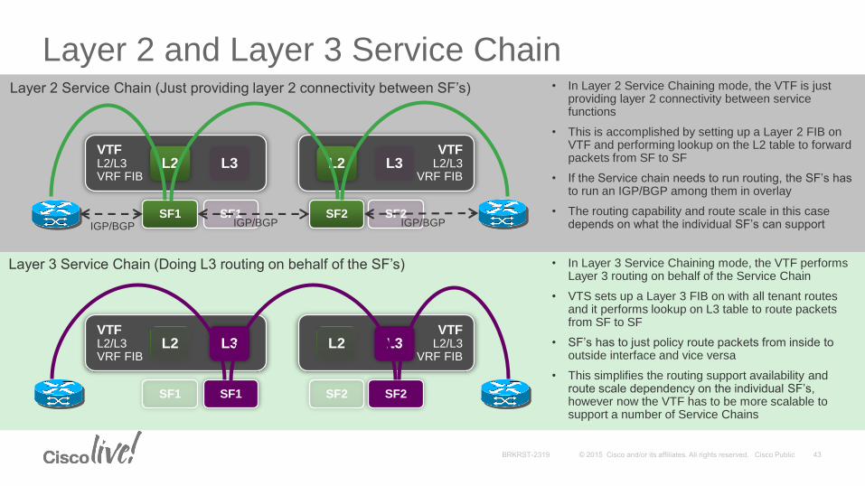
Layer 2 and Layer 3 Service Chain
SF1
VTFL2/L3VRF FIB
L2 L3
SF1 SF2
VTFL2/L3
VRF FIBL2 L3
SF2
SF1
VTFL2/L3VRF FIB
L2 L3
SF1 SF2
VTFL2/L3
VRF FIBL2 L3
SF2
IGP/BGP IGP/BGP IGP/BGP
Layer 2 Service Chain (Just providing layer 2 connectivity between SF’s)
Layer 3 Service Chain (Doing L3 routing on behalf of the SF’s)
• In Layer 2 Service Chaining mode, the VTF is just providing layer 2 connectivity between service functions
• This is accomplished by setting up a Layer 2 FIB on VTF and performing lookup on the L2 table to forward packets from SF to SF
• If the Service chain needs to run routing, the SF’s has to run an IGP/BGP among them in overlay
• The routing capability and route scale in this case depends on what the individual SF’s can support
• In Layer 3 Service Chaining mode, the VTF performs Layer 3 routing on behalf of the Service Chain
• VTS sets up a Layer 3 FIB on with all tenant routes and it performs lookup on L3 table to route packets from SF to SF
• SF’s has to just policy route packets from inside to outside interface and vice versa
• This simplifies the routing support availability and route scale dependency on the individual SF’s, however now the VTF has to be more scalable to support a number of Service Chains
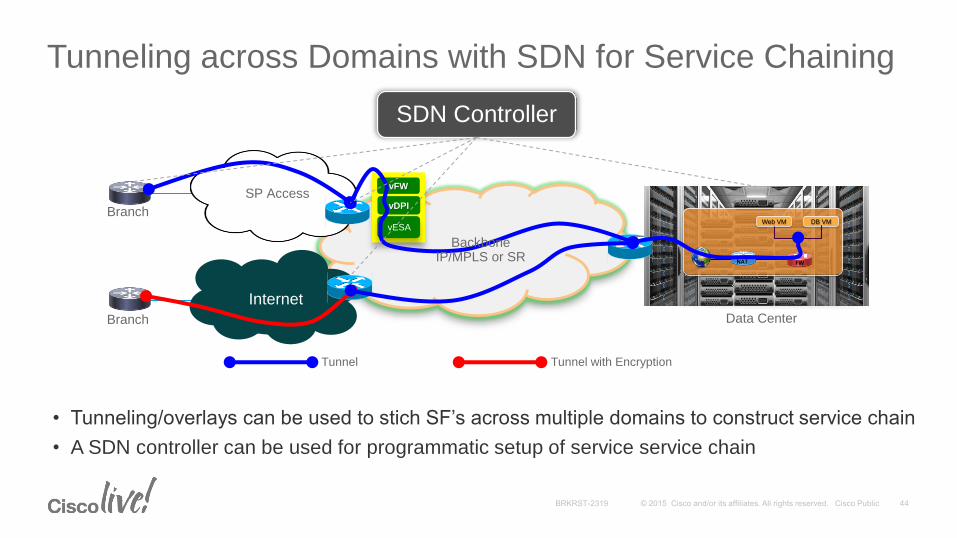
Tunneling across Domains with SDN for Service Chaining
vFW
vDPI
vESAWeb VM DB VM
FW NAT
Internet
SP Access
Backbone IP/MPLS or SR
Data CenterBranch
Branch
SDN Controller
Tunnel Tunnel with Encryption
• Tunneling/overlays can be used to stich SF’s across multiple domains to construct service chain
• A SDN controller can be used for programmatic setup of service service chain
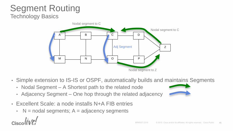
Segment Routing Technology Basics
• Simple extension to IS-IS or OSPF, automatically builds and maintains Segments
• Nodal Segment – A Shortest path to the related node
• Adjacency Segment – One hop through the related adjacency
• Excellent Scale: a node installs N+A FIB entries
• N = nodal segments; A = adjacency segments
A B C
M N O
Z
D
P
Nodal segment to C
Nodal segment to Z
Adj Segment
Nodal segment to C
45
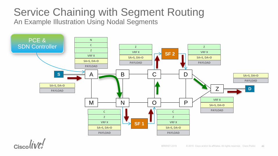
Service Chaining with Segment RoutingAn Example Illustration Using Nodal Segments
A B C
M N O
Z
D
P
S
D
SF 1
SF 2
PAYLOAD
SA=S, DA=D
PAYLOAD
SA=S, DA=D
Z
C
N
VRF X
PAYLOAD
SA=S, DA=D
Z
C
VRF X
PAYLOAD
SA=S, DA=D
Z
C
VRF X
PAYLOAD
SA=S, DA=D
Z
VRF X
PAYLOAD
SA=S, DA=D
Z
VRF X
PAYLOAD
SA=S, DA=D
VRF X
PAYLOAD
SA=S, DA=D
PCE &SDN Controller
46
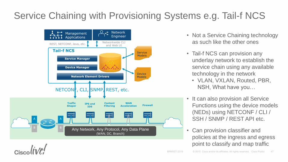
Service Chaining with Provisioning Systems e.g. Tail-f NCS
Traffic Shaper
IPS and IDS
Content Filtering
WAN Acceleration Firewall
A
B
A
B
Network Element Drivers
Device Manager
Service Manager
Tail-f NCS Service Models
Networkwide CLI and Web UI
REST, NETCONF, Java, etc.
Network Engineer
Management Applications
Device Models
Any Network, Any Protocol, Any Data Plane(WAN, DC, Branch)
NETCONF, CLI, SNMP, REST, etc.
• Not a Service Chaining technology
as such like the other ones
• Tail-f NCS can provision any
underlay network to establish the
service chain using any available
technology in the network
• VLAN, VXLAN, Routed, PBR,
NSH, What have you…
• It can also provision all Service
Functions using the device models
(NEDs) using NETCONF / CLI /
SSH / SNMP / REST API etc.
• Can provision classifier and
policies at the ingress and egress
point to classify and map traffic
Service Chaining Rationalization
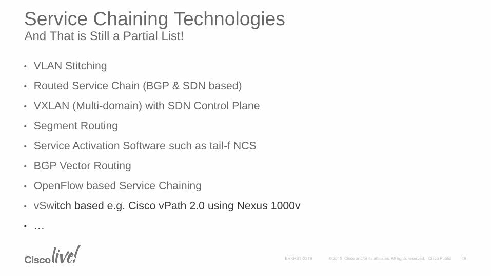
Service Chaining TechnologiesAnd That is Still a Partial List!
• VLAN Stitching
• Routed Service Chain (BGP & SDN based)
• VXLAN (Multi-domain) with SDN Control Plane
• Segment Routing
• Service Activation Software such as tail-f NCS
• BGP Vector Routing
• OpenFlow based Service Chaining
• vSwitch based e.g. Cisco vPath 2.0 using Nexus 1000v
• …

• Scalability
• Multi-domain capability
• Ease of Setup
• Is it Transport Agnostic ?
• E2E Service Chain OA&M
Common Parameters For Rationalization
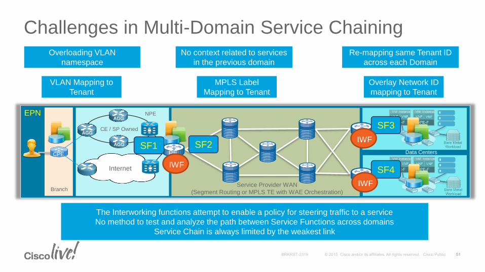
Challenges in Multi-Domain Service Chaining
VLAN Mapping to
Tenant
Overloading VLAN
namespace
MPLS Label
Mapping to Tenant
No context related to services
in the previous domain
Overlay Network ID
mapping to Tenant
Re-mapping same Tenant ID
across each Domain
The Interworking functions attempt to enable a policy for steering traffic to a service
No method to test and analyze the path between Service Functions across domains
Service Chain is always limited by the weakest link
DCI
DCI
EPN
BranchService Provider WAN
(Segment Routing or MPLS TE with WAE Orchestration)
CE / SP Owned
AGG
AGGNPE
Data CentersPE
Internet
CPE
AGG
SF1 SF2
SF3
SF4
IWF
IWF
IWF
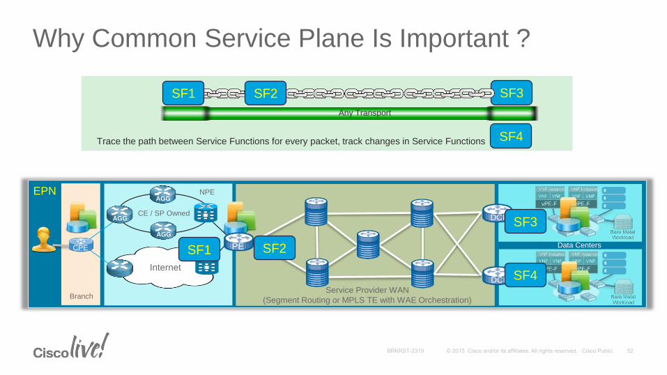
Why Common Service Plane Is Important ?
Trace the path between Service Functions for every packet, track changes in Service Functions
SF1 SF2 SF3
Any Transport
SF4
DCI
DCI
EPN
BranchService Provider WAN
(Segment Routing or MPLS TE with WAE Orchestration)
CE / SP Owned
AGG
AGGNPE
Data CentersPE
Internet
CPE
AGG
SF1 SF2
SF3
SF4
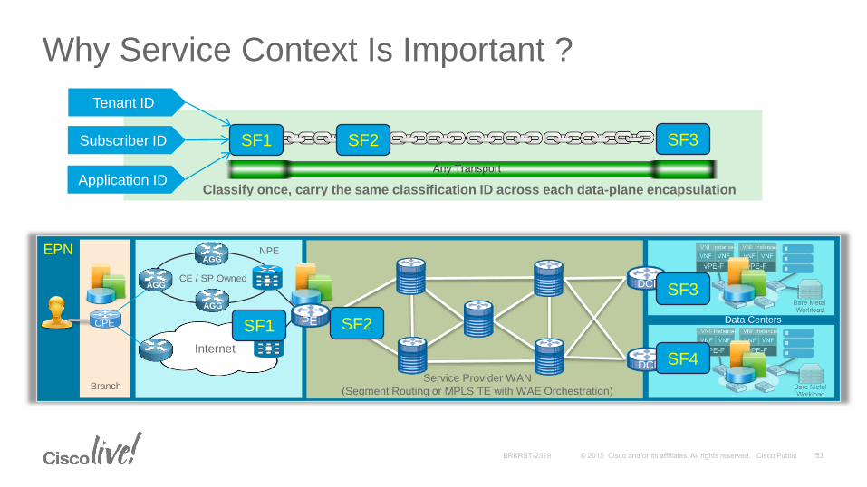
Why Service Context Is Important ?
SF1 SF2 SF3
Any Transport
DCI
DCI
EPN
BranchService Provider WAN
(Segment Routing or MPLS TE with WAE Orchestration)
CE / SP Owned
AGG
AGGNPE
Data CentersPE
Internet
CPE
AGG
SF1 SF2
SF3
SF4
Tenant ID
Subscriber ID
Application IDClassify once, carry the same classification ID across each data-plane encapsulation
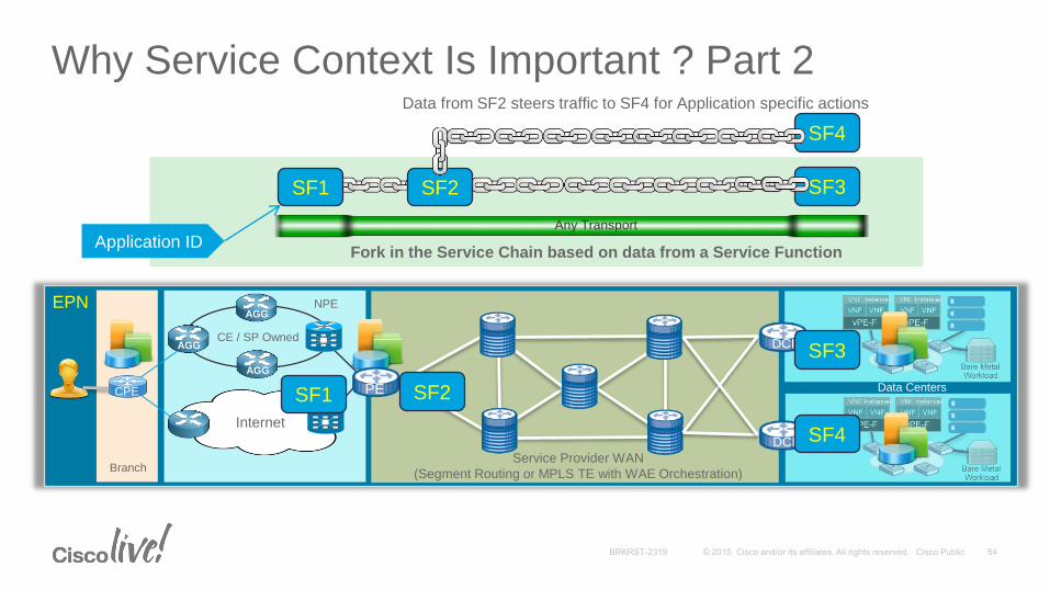
Why Service Context Is Important ? Part 2
SF1 SF2 SF3
Any Transport
Fork in the Service Chain based on data from a Service Function
SF4
Data from SF2 steers traffic to SF4 for Application specific actions
DCI
DCI
EPN
BranchService Provider WAN
(Segment Routing or MPLS TE with WAE Orchestration)
CE / SP Owned
AGG
AGGNPE
Data CentersPE
Internet
CPE
AGG
SF1 SF2
SF3
SF4
Application ID
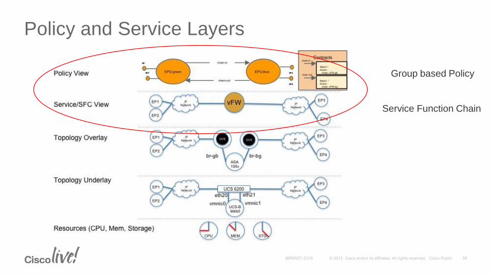
Policy and Service Layers
Group based Policy
Service Function Chain
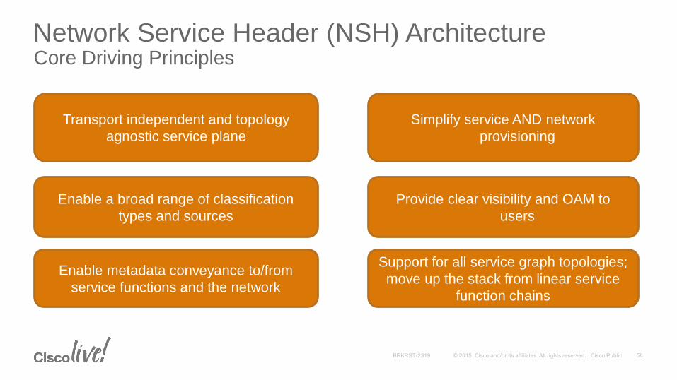
Network Service Header (NSH) ArchitectureCore Driving Principles
Transport independent and topology
agnostic service plane
Enable a broad range of classification
types and sources
Provide clear visibility and OAM to
users
Enable metadata conveyance to/from
service functions and the network
Support for all service graph topologies;
move up the stack from linear service
function chains
Simplify service AND network
provisioning
Cisco driving industry acceptance and standardization within the IETF
Service Function Chaining (SFC) working group http://datatracker.ietf.org/wg/sfc/charter/
Problem statement, use cases, and architecture WG documents
NSH gaining wide industry acceptance; many co-authors http://datatracker.ietf.org/doc/draft-quinn-sfc-nsh/
Also engaged with ETSI NFV, BBF, 3GPP, ONF, ATIS
Various open source engagements; OVS, OpenDaylight
Cisco & Intel have been jointly working to bring NSH offload support on the NIC
Network Service Header ArchitectureIndustry Acceptance and Standardization
57
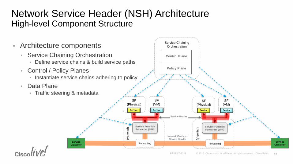
Architecture components
Service Chaining Orchestration Define service chains & build service paths
Control / Policy Planes Instantiate service chains adhering to policy
Data Plane Traffic steering & metadata
Network Service Header (NSH) ArchitectureHigh-level Component Structure
Service Chaining
Orchestration
SF
(VM)
Service
(v)s
witch
Forwarding
Service
Service
Classifier
SF
(Physical)
Serv
ice1
VLA
N
Service Function
Forwarder (SFF)
Control Plane
Policy Plane
SF
(VM)
Service
(v)s
witch
Forwarding
Service
SF
(Physical)
Serv
ice1
VLA
N
Service Function
Forwarder (SFF)
Service
Classifier
Network Overlay +
Service Header
Service Header
58
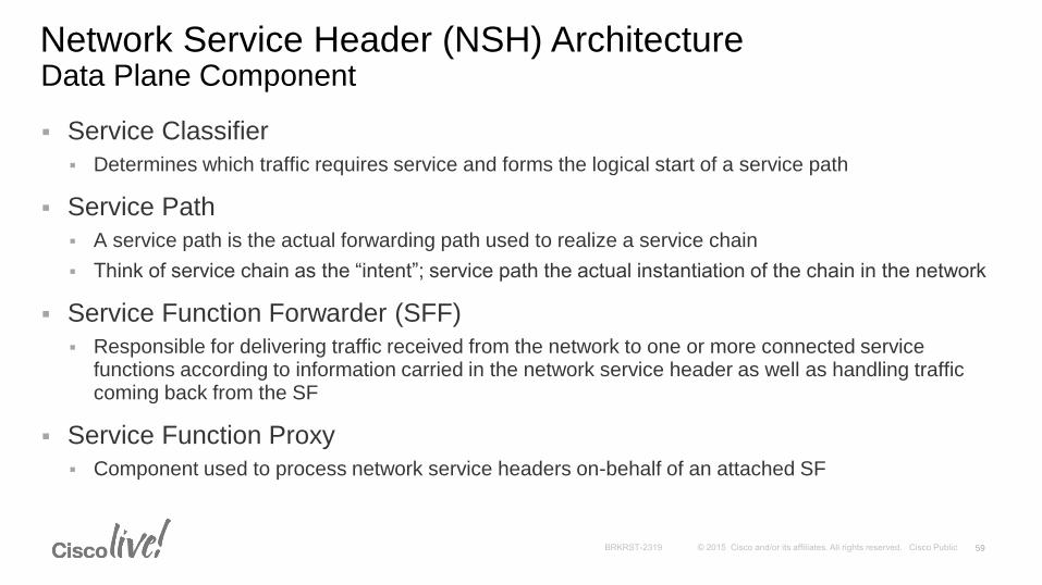
Service Classifier
Determines which traffic requires service and forms the logical start of a service path
Service Path
A service path is the actual forwarding path used to realize a service chain
Think of service chain as the “intent”; service path the actual instantiation of the chain in the network
Service Function Forwarder (SFF)
Responsible for delivering traffic received from the network to one or more connected service functions according to information carried in the network service header as well as handling traffic coming back from the SF
Service Function Proxy
Component used to process network service headers on-behalf of an attached SF
Network Service Header (NSH) ArchitectureData Plane Component
59
A Network Service Header (NSH) contains metadata and service path information that is added to a packet or frame and used to create a service plane. The packets and the NSH are then encapsulated in an outer header for transport.
More specifically NSH is composed of a 4-byte base header, a 4-byte service path header, four mandatory 4 byte context headers, and optional variable length context headers.
Base header: provides information about the service header and the payload
Service path header: provides path identification and location within a path
Mandatory context headers: carry opaque metadata
Optional variable length context headers: carry variable length TLV encoded information
Network Service Header (NSH)Data Plane Encapsulation
60
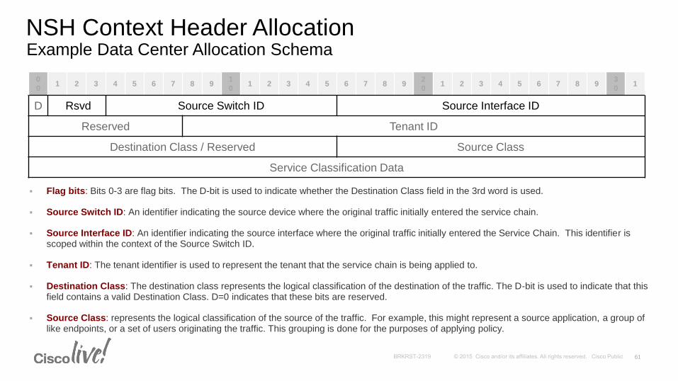
Flag bits: Bits 0-3 are flag bits. The D-bit is used to indicate whether the Destination Class field in the 3rd word is used.
Source Switch ID: An identifier indicating the source device where the original traffic initially entered the service chain.
Source Interface ID: An identifier indicating the source interface where the original traffic initially entered the Service Chain. This identifier is scoped within the context of the Source Switch ID.
Tenant ID: The tenant identifier is used to represent the tenant that the service chain is being applied to.
Destination Class: The destination class represents the logical classification of the destination of the traffic. The D-bit is used to indicate that this field contains a valid Destination Class. D=0 indicates that these bits are reserved.
Source Class: represents the logical classification of the source of the traffic. For example, this might represent a source application, a group of like endpoints, or a set of users originating the traffic. This grouping is done for the purposes of applying policy.
NSH Context Header AllocationExample Data Center Allocation Schema
0
01 2 3 4 5 6 7 8 9
1
01 2 3 4 5 6 7 8 9
2
01 2 3 4 5 6 7 8 9
3
01
D Rsvd Source Switch ID Source Interface ID
Reserved Tenant ID
Destination Class / Reserved Source Class
Service Classification Data
61

Legacy service functions may not have the capability to process packets encapsulated with a network service header
The network service header architecture introduces the concept of a “Service Proxy” that is responsible for processing of the network service headers and mapping to/from service functions
Allows for participant and non-participant services to co-exist and belong to the same service chain
Service Function ProxySupport for Participant / Non-Participant Services
SF
(VM)
TOR / (v)switch
SF
(Physical)
Service Function
Forwarder (SFF)
Service
Proxy
SF
(VM)SF
(Physical)
Participant Services Non-Participant Services
62
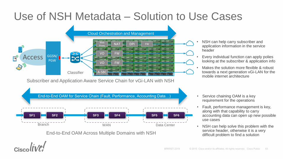
Use of NSH Metadata – Solution to Use Cases
Cloud Orchestration and Management
Access GGSN/PGW
Web Proxy NAT DPI FW
VO
VO FW
FW
A-SBC
12ABC
3DEF
4GHI
5JKL
6MNO
7
PQRS
8TUV
9
WXYZ
*0#
Signal Strength
Classifier
SF1 SF2 SF3 SF4 SF5 SF6
• NSH can help carry subscriber and application information in the service header
• Every individual function can apply polies looking at the subscriber & application info
• Makes the solution more flexible & robust towards a next generation vGi-LAN for the mobile internet architecture
• Service chaining OAM is a key requirement for the operations
• Fault, performance management is key, along with that capability to carry accounting data can open up new possible use cases
• NSH can help solve this problem with the service header, otherwise it is a very difficult problem to find a solution
WAN Data CenterBranch
End-to-End OAM for Service Chain (Fault, Performance, Accounting Data…)
Subscriber and Application Aware Service Chain for vGi-LAN with NSH
End-to-End OAM Across Multiple Domains with NSH
Service Chaining – Conclusion and Rationalization
• We need to lead with NSH to establish a common service plane
• With NSH we can get in-band policy and metadata support
• Can be a foundation to build a true cross-domain service chain
• NSH decouples service layer from the underlying transport layer, so it can leverage many other technologies across the network
• Its not NSH vs. Other technologies, its rather NSH + Other technologies to drive value
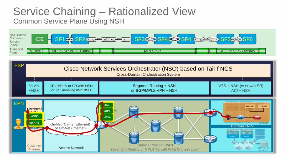
Service Chaining – Rationalized ViewCommon Service Plane Using NSH
DCI
DCI
EPN
Customer
Premise
Service Provider WAN
(Segment Routing or MPLS TE with WAE Orchestration)
Web VM DB VM
FW NAT
Access Network
VLAN
+NSH
CE / MPLS or SR with NSH
or IP Tunneling with NSH
Segment Routing + NSH
or BGP/MPLS VPN + NSH
VTS + NSH (w or w/o SR)
ACI + NSH
Cisco Network Services Orchestrator (NSO) based on Tail-f NCSCross-Domain Orchestration System
ESP
Distributed NFVI
vFW
vDPI
vESA
Distributed NFVI
SF2 SF3 SF4 SF5 SF6NSH Based Common Service Plane
Transport Plane VLAN MPLS/SR or IP Tunnel MPLS/SR ACI or VTS Overlay
SF4
CPE
Distributed NFVI
vCPE
vWAAS
PEOn-Net (Carrier Ethernet)
or Off-Net (Internet)
Service
Classifier SF1
vSwitch vSwitch
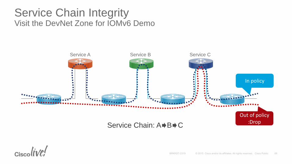
Service Chain IntegrityVisit the DevNet Zone for IOMv6 Demo
Service A Service B Service C
In policy
Out of policy:Drop
Service Chain: A B C
Participate in the “My Favorite Speaker” Contest
• Promote your favorite speaker through Twitter and you could win $200 of Cisco Press products (@CiscoPress)
• Send a tweet and include
• Your favorite speaker’s Twitter handle @cisco_kid_57767, @santanu1477
• Two hashtags: #CLUS #MyFavoriteSpeaker
• You can submit an entry for more than one of your “favorite” speakers
• Don’t forget to follow @CiscoLive and @CiscoPress
• View the official rules at http://bit.ly/CLUSwin
Promote Your Favorite Speaker and You Could Be a Winner
Complete Your Online Session Evaluation
Don’t forget: Cisco Live sessions will be available for viewing on-demand after the event at CiscoLive.com/Online
• Give us your feedback to be entered into a Daily Survey Drawing. A daily winner will receive a $750 Amazon gift card.
• Complete your session surveys though the Cisco Live mobile app or your computer on Cisco Live Connect.
Continue Your Education
• Demos in the Cisco campus
• Walk-in Self-Paced Labs
• Table Topics
• Meet the Engineer 1:1 meetings
• Related sessions
Thank you