Embed Size (px)
Citation preview
Third Edition
NetworkProtocols
Handbook
TCP/IP
Ethern
et A
TM
Frame R
elay W
AN LAN
MAN WLAN S
S7/C7 VOIP
Securit
y
VPN SAN
VLAN IE
EE IE
TF ISO
ITU-T
ANSI
Cisc
o IB
M
Apple Micro
soft
Novell
Javvin Technologies, Inc.
I Table of Contents
Table of Contents
Network Communication Architecture and Protocols•••••••••••••••••••••••••••••••••••••••••••••1
OSI Network Architecture 7 Layers Model•••••••••••••••••••••••••••••••••••••••••••••••••••••••••2
TCP/IP Four Layers Archiitecture Model••••••••••••••••••••••••••••••••••••••••••••••••••••••••••5
Other Network Architecture Models: IBM SNA•••••••••••••••••••••••••••••••••••••••••••••••••7
Network Protocols: Definition and Overview•••••••••••••••••••••••••••••••••••••••••••••••••••••9
Protocols Guide••••••••••••••••••••••••••••••••••••••••••••••••••••••••••••••••••••••••••••••••••••••••••••••11
TCP/IP Protocols••••••••••••••••••••••••••••••••••••••••••••••••••••••••••••••••••••••••••••••••••••••••••••••••••••••••••••••••••11
Application Layer Protocols••••••••••••••••••••••••••••••••••••••••••••••••••••••••••••••••••••••••••••••••••••••••••••••13
BOOTP: Bootstrap Protocol•••••••••••••••••••••••••••••••••••••••••••••••••••••••••••••••••••••••••••••••••••••13
DCAP: Data Link Switching Client Access Protocol••••••••••••••••••••••••••••••••••••••••••••••••••••••14
DHCP: Dynamic Host Configuration Protocol•••••••••••••••••••••••••••••••••••••••••••••••••••••••••••••••15
DNS: Domain Name System (Service) Protocol•••••••••••••••••••••••••••••••••••••••••••••••••••••••••••16
FTP: File Transfer Protocol••••••••••••••••••••••••••••••••••••••••••••••••••••••••••••••••••••••••••••••••••••17
Finger: User Information Protocol••••••••••••••••••••••••••••••••••••••••••••••••••••••••••••••••••••••••••••••19
HTTP: Hypertext Transfer Protocol••••••••••••••••••••••••••••••••••••••••••••••••••••••••••••••••••••••••••••20
S-HTTP: Secure Hypertext Transfer Protocol••••••••••••••••••••••••••••••••••••••••••••••••••••••••••••••21
IMAP & IMAP4: Internet Message Access Protocol (version 4)•••••••••••••••••••••••••••••••••••••••••22
IRCP: Internet Relay Chat Protocol••••••••••••••••••••••••••••••••••••••••••••••••••••••••••••••••••••••••••••24
LDAP: Lightweight Directory Access Protocol (version 3)••••••••••••••••••••••••••••••••••••••••••••••25
MIME (S-MIME): Multipurpose Internet Mail Extensions and Secure MIME•••••••••••••••••••••••26
NAT: Network Address Translation•••••••••••••••••••••••••••••••••••••••••••••••••••••••••••••••••••••••••••••27
NNTP: Network News Transfer Protocol•••••••••••••••••••••••••••••••••••••••••••••••••••••••••••••••••••••28
NTP: Network Time Protocol••••••••••••••••••••••••••••••••••••••••••••••••••••••••••••••••••••••••••••••••••••29
POP and POP3: Post Office Protocol (version 3)•••••••••••••••••••••••••••••••••••••••••••••••••••••••••••30
rlogin: Remote Login to Unix Systems••••••••••••••••••••••••••••••••••••••••••••••••••••••••••••••••••••••••••31
RMON: Remote Monitoring MIBs (RMON1 and RMON2)••••••••••••••••••••••••••••••••••••••••••••••••32
SLP: Service Location Protocol••••••••••••••••••••••••••••••••••••••••••••••••••••••••••••••••••••••••••••••••••34
SMTP: Simple Mail Transfer Protocol•••••••••••••••••••••••••••••••••••••••••••••••••••••••••••••••••••••••••35
SNMP: Simple Network Management Protocol••••••••••••••••••••••••••••••••••••••••••••••••••••••••••••••36
II Table of Contents
SNMPv1: Simple Network Management Protocol version one•••••••••••••••••••••••••••••••••••••••••37
SNMPv2: Simple Network Management Protocol version two•••••••••••••••••••••••••••••••••••••••38
SNMPv3: Simple Network Management Protocol version three••••••••••••••••••••••••••••••••••••••40
SNTP: Simple Network Time Protocol••••••••••••••••••••••••••••••••••••••••••••••••••••••••••••••••••••••••42
TELNET: Terminal Emulation Protocol of TCP/IP••••••••••••••••••••••••••••••••••••••••••••••••••••••••••44
TFTP: Trivial File Transfer Protocol••••••••••••••••••••••••••••••••••••••••••••••••••••••••••••••••••••••••••••45
URL: Uniform Resource Locator•••••••••••••••••••••••••••••••••••••••••••••••••••••••••••••••••••••••••••••••46
Whois (and RWhois): Remote Directory Access Protocol•••••••••••••••••••••••••••••••••••••••••••••••••47
XMPP: Extensible Messaging and Presence Protocol••••••••••••••••••••••••••••••••••••••••••••••••••48
X Window/X Protocol: X Window System Protocol••••••••••••••••••••••••••••••••••••••••••••••••••••••••••49
Presentation Layer Protocols•••••••••••••••••••••••••••••••••••••••••••••••••••••••••••••••••••••••••••••••••••••••••••••50
LPP: Lignhtweight Presentation Protocol•••••••••••••••••••••••••••••••••••••••••••••••••••••••••••••••••••••50
Session Layer Protocols••••••••••••••••••••••••••••••••••••••••••••••••••••••••••••••••••••••••••••••••••••••••••••••••••51
RPC: Remote Procedure Call Protocol•••••••••••••••••••••••••••••••••••••••••••••••••••••••••••••••••••••••51
Transport Layer Protocols••••••••••••••••••••••••••••••••••••••••••••••••••••••••••••••••••••••••••••••••••••••••••••••••53
ITOT: ISO Transport Service on top of TCP•••••••••••••••••••••••••••••••••••••••••••••••••••••••••••••••••53
RDP: Reliable Data Protocol•••••••••••••••••••••••••••••••••••••••••••••••••••••••••••••••••••••••••••••••••••••54
RUDP: Reliable User Datagram Protocol (Reliable UDP)•••••••••••••••••••••••••••••••••••••••••••••••56
TALI: Tekelec’s Transport Adapter Layer Interface•••••••••••••••••••••••••••••••••••••••••••••••••••••••57
TCP: Transmission Control Protocol••••••••••••••••••••••••••••••••••••••••••••••••••••••••••••••••••••••••••58
UDP: User Datagram Protocol•••••••••••••••••••••••••••••••••••••••••••••••••••••••••••••••••••••••••••••••••60
Van Jacobson: Compressed TCP Protocol••••••••••••••••••••••••••••••••••••••••••••••••••••••••••••••••••••61
Network Layer Protocols••••••••••••••••••••••••••••••••••••••••••••••••••••••••••••••••••••••••••••••••••••••••••••••••••62
Routing Protocols••••••••••••••••••••••••••••••••••••••••••••••••••••••••••••••••••••••••••••••••••••••••••••••••••••••••62
BGP (BGP-4): Border Gateway Protocol••••••••••••••••••••••••••••••••••••••••••••••••••••••••••••••••••••••62
EGP: Exterior Gateway Protocol••••••••••••••••••••••••••••••••••••••••••••••••••••••••••••••••••••••••••••••••63
IP: Internet Protocol (IPv4)••••••••••••••••••••••••••••••••••••••••••••••••••••••••••••••••••••••••••••••••••••••64
IPv6: Internet Protocol version 6•••••••••••••••••••••••••••••••••••••••••••••••••••••••••••••••••••••••••••••••••66
ICMP & ICMPv6: Internet Message Control Protocol and ICMP version 6••••••••••••••••••••••••••••••68
IRDP: ICMP Router Discovery Protocol••••••••••••••••••••••••••••••••••••••••••••••••••••••••••••••••••••••••70
Mobile IP: IP Mobility Support Protocol for IPv4 & IPv6•••••••••••••••••••••••••••••••••••••••••••••••••••••71
NARP: NBMA Address Resolution Protocol•••••••••••••••••••••••••••••••••••••••••••••••••••••••••••••••••••73
NHRP: Next Hop Resolution Protocol•••••••••••••••••••••••••••••••••••••••••••••••••••••••••••••••••••••••••74

III Table of Contents
OSPF: Open Shortest Path Firest Protocol•••••••••••••••••••••••••••••••••••••••••••••••••••••••••••••••••75
RIP: Routing Information Protocol (RIP2)•••••••••••••••••••••••••••••••••••••••••••••••••••••••••••••••••••••76
RIPng: Routing Information Protocol next generation for IPv6•••••••••••••••••••••••••••••••••••••••••77
RSVP: Resource ReSerVation Protocol•••••••••••••••••••••••••••••••••••••••••••••••••••••••••••••••••••••••78
VRRP: Virtual Router Redundancy Protocol••••••••••••••••••••••••••••••••••••••••••••••••••••••••••••••••79
Multicasting Protocols••••••••••••••••••••••••••••••••••••••••••••••••••••••••••••••••••••••••••••••••••••••••••••••••••80
BGMP: Border Gateway Multicast Protocol••••••••••••••••••••••••••••••••••••••••••••••••••••••••••••••••••80
DVMRP: Distance Vector Multicast Routing Protocol••••••••••••••••••••••••••••••••••••••••••••••••••••••81
IGMP : Internet Group Management Protocol•••••••••••••••••••••••••••••••••••••••••••••••••••••••••••••••••82
MARS: Multicast Address Resolution Server••••••••••••••••••••••••••••••••••••••••••••••••••••••••••••••••83
MBGP: Multiprotocol BGP•••••••••••••••••••••••••••••••••••••••••••••••••••••••••••••••••••••••••••••••••••••••84
MOSPF: Multicast Extensions to OSPF••••••••••••••••••••••••••••••••••••••••••••••••••••••••••••••••••••••86
MSDP: Multicast Source Discovery Protocol••••••••••••••••••••••••••••••••••••••••••••••••••••••••••••••••87
MZAP: Multicast-Scope Zone Anncuncement Protocol•••••••••••••••••••••••••••••••••••••••••••••••••••88
PGM: Pragmatic General Multicast Protocol•••••••••••••••••••••••••••••••••••••••••••••••••••••••••••••••••89
PIM-DM: Protocol Independent Multicast - Dense Mode••••••••••••••••••••••••••••••••••••••••••••••••••90
PIM-SM: Protocol Independent Multicast - Sparse Mode•••••••••••••••••••••••••••••••••••••••••••••••••••91
MPLS Protocols•••••••••••••••••••••••••••••••••••••••••••••••••••••••••••••••••••••••••••••••••••••••••••••••••••••••••••92
MPLS: Multiprotocol Label Switching•••••••••••••••••••••••••••••••••••••••••••••••••••••••••••••••••••••••••92
GMPLS: Generalized Multiprotocol Label Switching••••••••••••••••••••••••••••••••••••••••••••••••••••••••94
CR-LDP: Constraint-based LDP•••••••••••••••••••••••••••••••••••••••••••••••••••••••••••••••••••••••••••••••••95
LDP: Label Distribution Protocol••••••••••••••••••••••••••••••••••••••••••••••••••••••••••••••••••••••••••••••••96
RSVP-TE: Resource Reservation Protocol - Traffic Extension••••••••••••••••••••••••••••••••••••••••••97
Data Link Layer Protocols•••••••••••••••••••••••••••••••••••••••••••••••••••••••••••••••••••••••••••••••••••••••••••••••••98
ARP and InARP: Address Resolution Protocol and Inverse ARP••••••••••••••••••••••••••••••••••••••••98
IPCP and IPv6CP: IP Control Protocol and IPv6 Control Protocol••••••••••••••••••••••••••••••••••••••99
RARP: Reverse Address Resolution Protocol•••••••••••••••••••••••••••••••••••••••••••••••••••••••••••••••100
SLIP: Serial Line IP••••••••••••••••••••••••••••••••••••••••••••••••••••••••••••••••••••••••••••••••••••••••••••••101
Network Security Technologies and Protocols•••••••••••••••••••••••••••••••••••••••••••••••••••••••••••••••••102
AAA Protocols••••••••••••••••••••••••••••••••••••••••••••••••••••••••••••••••••••••••••••••••••••••••••••••••••••••••••••••104
Kerberos: Network Authentication Protocol••••••••••••••••••••••••••••••••••••••••••••••••••••••••••••••••••104
RADIUS: Remote Authentication Dial in User Service•••••••••••••••••••••••••••••••••••••••••••••••••••105
IV Table of Contents
SSH: Secure Shell Protocolsl••••••••••••••••••••••••••••••••••••••••••••••••••••••••••••••••••••••••••••••••••106
Tunneling Protocols•••••••••••••••••••••••••••••••••••••••••••••••••••••••••••••••••••••••••••••••••••••••••••••••••••••••107
L2F: Layer 2 Forwarding Protocol••••••••••••••••••••••••••••••••••••••••••••••••••••••••••••••••••••••••••••••107
L2TP: Layer 2 Tunneling Protocol•••••••••••••••••••••••••••••••••••••••••••••••••••••••••••••••••••••••••••••108
PPTP: Point-to-Point Tunneling Protocol••••••••••••••••••••••••••••••••••••••••••••••••••••••••••••••••••••110
Secured Routing Protocols•••••••••••••••••••••••••••••••••••••••••••••••••••••••••••••••••••••••••••••••••••••••••••••111
DiffServ: Differentiated Service Architecture••••••••••••••••••••••••••••••••••••••••••••••••••••••••••••••••111
GRE: Generic Routing Encapsulation••••••••••••••••••••••••••••••••••••••••••••••••••••••••••••••••••••••••112
IPSec: Internet Protocol Security Architecture•••••••••••••••••••••••••••••••••••••••••••••••••••••••••••••113
IPSec AH: IPsec Authentication Header•••••••••••••••••••••••••••••••••••••••••••••••••••••••••••••••••••114
IPsec ESP: IPsec Encapsulating Security Payload•••••••••••••••••••••••••••••••••••••••••••••••••••••••115
IPsec IKE: Internet Key Exchange Protocol•••••••••••••••••••••••••••••••••••••••••••••••••••••••••••••••••116
IPsec ISAKMP: Internet Security Association and Key Management Protocol•••••••••••••••••••••117
SSL/TLS: Secure Socket Layer and Transport Layer Security Protocol•••••••••••••••••••••••••••••118
Other Security Protocols•••••••••••••••••••••••••••••••••••••••••••••••••••••••••••••••••••••••••••••••••••••••••••••••••120
SOCKS v5: Protocol for Sessions Traversal Across Firewall Securely••••••••••••••••••••••••••••••120
Voice over IP and VOIP Protocols•••••••••••••••••••••••••••••••••••••••••••••••••••••••••••••••••••••••••••••••••••••121
Signalling•••••••••••••••••••••••••••••••••••••••••••••••••••••••••••••••••••••••••••••••••••••••••••••123
H.323: ITU-T VOIP Protocols•••••••••••••••••••••••••••••••••••••••••••••••••••••••••••••••••••••••••••••••••123
H.225.0: Vall signalling protocols and media stream packetization for packet based multimedia
communication systems•••••••••••••••••••••••••••••••••••••••••••••••••••••••••••••••••••••••••••••••••••••••••125
H.235: Security and encryption for H-series (H.323 and other H.245-based) multimediateminals
•••••••••••••••••••••••••••••••••••••••••••••••••••••••••••••••••••••••••••••••••••••••••••••••127
H.245: Control Protocol for Multimedia Communication•••••••••••••••••••••••••••••••••••••••••••••••••128
Megaco/H.248: Media Gateway Control Protocol•••••••••••••••••••••••••••••••••••••••••••••••••••••••••••129
MGCP: Media Gateway Control Protocol•••••••••••••••••••••••••••••••••••••••••••••••••••••••••••••••••••••130
NCS: Network-Based Call Signaling Protocol ••••••••••••••••••••••••••••••••••••••••••••••••••••••••••••••131
RTSP: Real-Time Streaming Protocol•••••••••••••••••••••••••••••••••••••••••••••••••••••••••••••••••••••••132
SAP: Session Announcement Protocols•••••••••••••••••••••••••••••••••••••••••••••••••••••••••••••••••••••134
SDP: Session Description Protocol•••••••••••••••••••••••••••••••••••••••••••••••••••••••••••••••••••••••••••135
SIP: Session Initiation Protocol•••••••••••••••••••••••••••••••••••••••••••••••••••••••••••••••••••••••••••••••••136
SCCP (Skinny): Cisco Skinny Client Control Protocol•••••••••••••••••••••••••••••••••••••••••••••••••••138

V Table of Contents
T.120: Multipoint Data Conferencing and Real Time Communication Protocols••••••••••••••••••••••140
Media/CODEC••••••••••••••••••••••••••••••••••••••••••••••••••••••••••••••••••••••••••••••••••••••••••••142
G.7xx: Audio (Voice) Compression Protocols••••••••••••••••••••••••••••••••••••••••••••••••••••••••••••••142
H.261: Video CODEC for Low Quality Videoconferencing••••••••••••••••••••••••••••••••••••••••••••••••144
H.263: Video CODEC for Medium Quality Videoconferencing•••••••••••••••••••••••••••••••••••••••••••••145
H.264 / MPEG-4: Video CODEC For High Quality Video Streaming••••••••••••••••••••••••••••••••••••••147
RTP: Real-Time Transport Protocol••••••••••••••••••••••••••••••••••••••••••••••••••••••••••••••••••••••••••149
RTCP: RTP Control Protocol••••••••••••••••••••••••••••••••••••••••••••••••••••••••••••••••••••••••••••••••••150
Other Protocols•••••••••••••••••••••••••••••••••••••••••••••••••••••••••••••••••••••••••••••••••••••••••••••••••••••••••••••151
COPS: Common Open Policy Service•••••••••••••••••••••••••••••••••••••••••••••••••••••••••••••••••••••••••151
SIGTRAN: Signaling Transport Protocol Stack•••••••••••••••••••••••••••••••••••••••••••••••••••••••••••••152
SCTP: Stream Control Transmission Protocol••••••••••••••••••••••••••••••••••••••••••••••••••••••••••••154
TRIP: Telephony Routing over IP•••••••••••••••••••••••••••••••••••••••••••••••••••••••••••••••••••••••••••••155
Wide Area Network and Wan Protocols••••••••••••••••••••••••••••••••••••••••••••••••••••••••••••••••••••••••••••156
ATM Protocols•••••••••••••••••••••••••••••••••••••••••••••••••••••••••••••••••••••••••••••••••••••••••••••••••••••••••••••••158
ATM: Asynchronous Transfer Mode•••••••••••••••••••••••••••••••••••••••••••••••••••••••••••••••••••••••••158
ATM Layer: Asynchronous Transfer Mode Layer•••••••••••••••••••••••••••••••••••••••••••••••••••••••••159
AAL: ATM Adaptation Layers (AAL1, AAL2, AAL3/4, AAL5)•••••••••••••••••••••••••••••••••••••••••160
ATM UNI: ATM Signaling User-to-Network Interface•••••••••••••••••••••••••••••••••••••••••••••••••••••163
LANE NNI: ATM LAN Emulation NNI•••••••••••••••••••••••••••••••••••••••••••••••••••••••••••••••••••••••••165
LANE UNI: ATM LAN Emulation UNI•••••••••••••••••••••••••••••••••••••••••••••••••••••••••••••••••••••••••167
MPOA: Multi-Protocol Over ATM••••••••••••••••••••••••••••••••••••••••••••••••••••••••••••••••••••••••••••••169
ATM PNNI: ATM Private Network-toNetwork Interface•••••••••••••••••••••••••••••••••••••••••••••••••••171
Q.2931: ATM Signaling for B-ISDN••••••••••••••••••••••••••••••••••••••••••••••••••••••••••••••••••••••••••172
SONET/SDH: Synchronous Optical Network and Synchronous Digital Hierarchy••••••••••••174
EoS: Ethernet over SONET/SDH••••••••••••••••••••••••••••••••••••••••••••••••••••••••••••••••••••••••••••••176
Broadband Access Protocols••••••••••••••••••••••••••••••••••••••••••••••••••••••••••••••••••••••••••••••••••••••••••178
BISDN: Broadband Integrated Services Digital Network (Broadband ISDN)••••••••••••••••••••178
ISDN: Integrated Services Digital Network•••••••••••••••••••••••••••••••••••••••••••••••••••••••••••••••••179
LAP-D: ISDN Link Access Protocol-Channel D•••••••••••••••••••••••••••••••••••••••••••••••••••••••••••181
Q.931: ISDN Network Layer Protocol for Signaling•••••••••••••••••••••••••••••••••••••••••••••••••••••183
DOCSIS: Data Over Cable Service Interface Specification••••••••••••••••••••••••••••••••••••••••••••••184
VI Table of Contents
xDSL: Digital Subscriber Line Technologies (DSL, IDSL, ADSL, HDSL, SDSL,VDSL,G.Lite)•••185
PPP Protocols•••••••••••••••••••••••••••••••••••••••••••••••••••••••••••••••••••••••••••••••••••••••••••••••••••••••••••••••186
PPP: Point-to-Point Protocols••••••••••••••••••••••••••••••••••••••••••••••••••••••••••••••••••••••••••••••••••186
BAP: PPP Bandwidth Allocation Protocol(BAP) and BACP: PPP Banwidth Allocation Control
Protocol (BACP)••••••••••••••••••••••••••••••••••••••••••••••••••••••••••••••••••••••••••••••••••••••••••••••••••187
BCP: PPP Briding Control Protocol•••••••••••••••••••••••••••••••••••••••••••••••••••••••••••••••••••••••••••188
EAP: PPP Extensible Authentication Protocol•••••••••••••••••••••••••••••••••••••••••••••••••••••••••••••189
CHAP: Challenge Handshake Authentication Protocol•••••••••••••••••••••••••••••••••••••••••••••••••••190
LCP: PPP Link Control Protocol••••••••••••••••••••••••••••••••••••••••••••••••••••••••••••••••••••••••••••••••191
MP: MultiLink Point to Point Protocol (MultiPPP)••••••••••••••••••••••••••••••••••••••••••••••••••••••••••192
PPP NCP: Point to Point Protocol Network Control Protocols•••••••••••••••••••••••••••••••••••••••••193
PAP: Password Authentication Protocol•••••••••••••••••••••••••••••••••••••••••••••••••••••••••••••••••••••194
PoS: Packet over SONET/SDH•••••••••••••••••••••••••••••••••••••••••••••••••••••••••••••••••••••••••••••••195
PPPoA: PPP over ATM AAL5••••••••••••••••••••••••••••••••••••••••••••••••••••••••••••••••••••••••••••••••••196
PPPoE: PPP over Ethernet•••••••••••••••••••••••••••••••••••••••••••••••••••••••••••••••••••••••••••••••••••••197
Other WAN Protocols•••••••••••••••••••••••••••••••••••••••••••••••••••••••••••••••••••••••••••••••••••••••••••••••••••••198
Frame Relay: WAN Protocol for Internetworking•••••••••••••••••••••••••••••••••••••••••••••••••••••••••198
LAPF: Link Access Procedure for Frame Mode Services•••••••••••••••••••••••••••••••••••••••••••••••200
HDLC: High Level Data Link Control••••••••••••••••••••••••••••••••••••••••••••••••••••••••••••••••••••••••••201
LAPB: Link Access Procedure, Balanced•••••••••••••••••••••••••••••••••••••••••••••••••••••••••••••••••••202
X.25: ISO/ITU-T Protocol for WAN Communications••••••••••••••••••••••••••••••••••••••••••••••••••••••203
Local Area Network and LAN Protocols••••••••••••••••••••••••••••••••••••••••••••••••••••••••••••••••••••••••••••205
Ethernet Protocols•••••••••••••••••••••••••••••••••••••••••••••••••••••••••••••••••••••••••••••••••••••••••••••••••••••••••206
Ethernet: IEEE 802.3 Local Area Network Protocols•••••••••••••••••••••••••••••••••••••••••••••••••••••206
Fast Ethernet: 100Mbps Ethernet (IEEE 802.3u)••••••••••••••••••••••••••••••••••••••••••••••••••••••••••208
Gigabit (1000 Mbps) Ethernet: IEEE 802.3z (1000Base-X) and 802.3ab (1000 Base-T)•••209
10 Gigabit Ethernet: The Ethernet Protocol IEEE 802.3ae for LAN, WAN and MAN•••••••••••211
Virtual LAN Protocols••••••••••••••••••••••••••••••••••••••••••••••••••••••••••••••••••••••••••••••••••••••••••••••••••••••213
VLAN: Virtual Local Area Network and the IEEE 802.1Q••••••••••••••••••••••••••••••••••••••••••••••213
IEEE 802.1P: LAN Layer 2 QoS/CoS Protocol for Traffic Prioritization••••••••••••••••••••••••••••••••215
GARP: Generic Attribute Registration Protocol••••••••••••••••••••••••••••••••••••••••••••••••••••••••••••217
GMRP: GARP Multicast Registration Protocol••••••••••••••••••••••••••••••••••••••••••••••••••••••••••••••218

VII Table of Contents
GVRP: GARP VLAN Registration Protocol•••••••••••••••••••••••••••••••••••••••••••••••••••••••••••••••••219
Wilress LAN Protocols••••••••••••••••••••••••••••••••••••••••••••••••••••••••••••••••••••••••••••••••••••••••••••••••••••220
WLAN: Wireless LAN by IEEE 802.11 Protocols•••••••••••••••••••••••••••••••••••••••••••••••••••••••••220
IEEE 802.11i: WLAN Security Standard•••••••••••••••••••••••••••••••••••••••••••••••••••••••••••••••••••••222
IEEE 802.1X: EAP over LAN (EAPOL) for LAN/WLAN Authentication and Key Management•••224
IEEE 802.15 and the Bluetooth: WPAN Communications•••••••••••••••••••••••••••••••••••••••••••••••226
Other Protocols•••••••••••••••••••••••••••••••••••••••••••••••••••••••••••••••••••••••••••••••••••••••••••••••••••••••••••••227
FDDI: Fiber Distributed Data Interface•••••••••••••••••••••••••••••••••••••••••••••••••••••••••••••••••••••••227
Token Ring: IEEE 802.5 LAN Protocol•••••••••••••••••••••••••••••••••••••••••••••••••••••••••••••••••••••••228
LLC: Logic Link Control (IEEE 802.2)•••••••••••••••••••••••••••••••••••••••••••••••••••••••••••••••••••••••229
SNAP: SubNetwork Access Protocol••••••••••••••••••••••••••••••••••••••••••••••••••••••••••••••••••••••••230
STP: Spanning Tree Protocol (IEEE 802.1D)••••••••••••••••••••••••••••••••••••••••••••••••••••••••••••231
Metropolitan Area Network and MAN Protocol••••••••••••••••••••••••••••••••••••••••••••••••233
DQDB: Distributed Queue Dual Bus (Defined in IEEE 802.6)•••••••••••••••••••••••••••••••••••••••••••234
SMDS: Switched Multimegabit Data Service•••••••••••••••••••••••••••••••••••••••••••••••••••••••••••••••235
IEEE 802.16: Broadband Wireless MAN Standard (WiMAX)•••••••••••••••••••••••••••••••••••••••••••237
Storage Area Network and SAN Protocols•••••••••••••••••••••••••••••••••••••238 FC & FCP: Fibre Channel and Fibre Channel Protocol•••••••••••••••••••••••••••••••••••••••••••••••••••••240
FCIP: Fibre Channel over TCP/IP•••••••••••••••••••••••••••••••••••••••••••••••••••••••••••••••••••••••••••••241
iFCP: Internet Fibre Channel Protocol•••••••••••••••••••••••••••••••••••••••••••••••••••••••••••••••••••••••243
iSCSI: Internet Small Computer System Interface (SCSI)••••••••••••••••••••••••••••••••••••••••••••••••245
iSNS and iSNSP: Internet Storage Name Service and iSNS Protocol••••••••••••••••••••••••••••••••••••247
NDMP: Network Data Management Protocol••••••••••••••••••••••••••••••••••••••••••••••••••••••••••••••248
SCSI: Small Computer System Interface••••••••••••••••••••••••••••••••••••••••••••••••••••••••••••••••••250
ISO Protocols in OSI 7 Layers Model••••••••••••••••••••••••••••••••••••••••••••••••••••••••••252
Application Layer••••••••••••••••••••••••••••••••••••••••••••••••••••••••••••••••••••••••••••••••••••••••••••••••••••••••••254
ISO ACSE: Association Control Service Element••••••••••••••••••••••••••••••••••••••••••••••••••••••••254
ISO CMIP: Common Management Information Protocol•••••••••••••••••••••••••••••••••••••••••••••••••256
CMOT: CMIP over TCP/IP••••••••••••••••••••••••••••••••••••••••••••••••••••••••••••••••••••••••••••••••••••••258
ISO FTAM: File Transfer Access and Management Protocol•••••••••••••••••••••••••••••••••••••••••••••259

VIII Table of Contents
ISO ROSE: Remote Operations Service Element Protocol••••••••••••••••••••••••••••••••••••••••••••260
ISO RTSE: Reliable Transfer Service Element Protocol••••••••••••••••••••••••••••••••••••••••••••••••262
ISO VTP: ISO Virtual Terminal (VT) Protocol••••••••••••••••••••••••••••••••••••••••••••••••••••••••••••••263
X.400: Message Handling Service Protocol•••••••••••••••••••••••••••••••••••••••••••••••••••••••••••••••264
X.500: Directory Access Protocol (DAP)•••••••••••••••••••••••••••••••••••••••••••••••••••••••••••••••••••266
ASN.1: Abstract Syntax Notation One•••••••••••••••••••••••••••••••••••••••••••••••••••••••••••••••••••••••267
ISO-PP: OSI Presentation Protocol••••••••••••••••••••••••••••••••••••••••••••••••••••••••••••••••••••••••••268
ISO-SP: OSI Session Protocol••••••••••••••••••••••••••••••••••••••••••••••••••••••••••••••••••••••••••••••••270
ISO-TP: OSI Transport Layer Protocols TP0, TP1, TP2, TP3, TP4••••••••••••••••••••••••••••••••••••271
Network Layer••••••••••••••••••••••••••••••••••••••••••••••••••••••••••••••••••••••••••••••••••••••••••••••••••••••••••••••273
CLNP: Connectionless Network Protocol (ISO-IP)•••••••••••••••••••••••••••••••••••••••••••••••••••••••273
ISO CONP: Connection-Oriented Network Protocol•••••••••••••••••••••••••••••••••••••••••••••••••••••275
ES-IS: End System to Intermediate System Routing Exchange Protocol•••••••••••••••••••••••••276
IDRP: Inter-Domain Routing Protocol••••••••••••••••••••••••••••••••••••••••••••••••••••••••••••••••••••••••277
IS-IS: Intermediate System to Intermediate System Routing Protocol••••••••••••••••••••••••••••••278
Cisco Protocols•••••••••••••••••••••••••••••••••••••••••••••••••••••••••••••••••••••••••••••••••••••279
CDP: Cisco Discovery Protocol•••••••••••••••••••••••••••••••••••••••••••••••••••••••••••••••••••••••••••••••280
CGMP: Cisco Group Management Protocol••••••••••••••••••••••••••••••••••••••••••••••••••••••••••••••••281
DTP: Cisco Dynamic Trunking Protocol••••••••••••••••••••••••••••••••••••••••••••••••••••••••••••••••••••••282
EIGRP: Enhanced Interior Gateway Routing Protocol•••••••••••••••••••••••••••••••••••••••••••••••••••283
HSRP: Hot Standby Router Protocol••••••••••••••••••••••••••••••••••••••••••••••••••••••••••••••••••••••••284
IGRP: Interior Gateway Routing Protocol•••••••••••••••••••••••••••••••••••••••••••••••••••••••••••••••••••285
ISL & DISL: Cisco Inter-Switch Link Protocol and Dynamic ISL Protocol••••••••••••••••••••••••••••286
RGMP: Cisco Router Port Group Management Protocol•••••••••••••••••••••••••••••••••••••••••••••••287
TACACS (and TACACS+): Terminal Access Controller Access Control System••••••••••••••••288
VTP: Cisco VLAN Trunking Protocol••••••••••••••••••••••••••••••••••••••••••••••••••••••••••••••••••••••••••289
XOT: X.25 over TCP Protocol by Cisco•••••••••••••••••••••••••••••••••••••••••••••••••••••••••••••••••••••••291
Novell NetWare and Protocols••••••••••••••••••••••••••••••••••••••••••••••••••••••••••••••••••292
IPX: Internetwork Packet Exchange Protocol•••••••••••••••••••••••••••••••••••••••••••••••••••••••••••••••294
NCP: NetWare Core Protocol•••••••••••••••••••••••••••••••••••••••••••••••••••••••••••••••••••••••••••••••••••295
NLSP: NetWare Link Services Protocol••••••••••••••••••••••••••••••••••••••••••••••••••••••••••••••••••••••296

IX Table of Contents
SPX: Sequenced Packet Exchange Protocol•••••••••••••••••••••••••••••••••••••••••••••••••••••••••••••298
IBM Systems Network Architecture (SNA) and Protocols•••••••••••••••••••••••••••••••••299
IBM SMB: Server Message Block Protocol••••••••••••••••••••••••••••••••••••••••••••••••••••••••••••••••301
APPC: Advanced Program to Program Communications (SNA LU6.2)••••••••••••••••••••••••••••••302
SNA NAU: Network Accessible Units (PU, LU and CP)•••••••••••••••••••••••••••••••••••••••••••••••••303
NetBIOS: Network Basic Input Output System•••••••••••••••••••••••••••••••••••••••••••••••••••••••••••305
NetBEUI: NetBIOS Extended User Interface••••••••••••••••••••••••••••••••••••••••••••••••••••••••••••••306
APPN: Advanced Peer-to-Peer Networking••••••••••••••••••••••••••••••••••••••••••••••••••••••••••••••••307
DLSw: Data-Link Switching Protocol•••••••••••••••••••••••••••••••••••••••••••••••••••••••••••••••••••••••••309
QLLC: Qualified Logic Link Control•••••••••••••••••••••••••••••••••••••••••••••••••••••••••••••••••••••••••••310
SDLC: Synchronous Data Link Control••••••••••••••••••••••••••••••••••••••••••••••••••••••••••••••••••••••311
AppleTalk: Apple Computer Protocols Suite••••••••••••••••••••••••••••••••••••••••••••••••••312
DECnet and Protocols•••••••••••••••••••••••••••••••••••••••••••••••••••••••••••••••••••••••••••••314
SS7/C7 Protocols: Signalling System #7 for Telephony •••••••••••••••••••••••••••••••••••••316
BISUP: Broadband ISDN User Part••••••••••••••••••••••••••••••••••••••••••••••••••••••••••••••••••••••••••318
DUP: Data User Part••••••••••••••••••••••••••••••••••••••••••••••••••••••••••••••••••••••••••••••••••••••••••••319
ISUP: ISDN User Part•••••••••••••••••••••••••••••••••••••••••••••••••••••••••••••••••••••••••••••••••••••••••••320
MAP: Mobile Application Part•••••••••••••••••••••••••••••••••••••••••••••••••••••••••••••••••••••••••••••••••322
MTP2 and MTP3: Message Transfer Part level 2 and level 3•••••••••••••••••••••••••••••••••••••••••323
SCCP: Signalling Connection Control Part of SS7•••••••••••••••••••••••••••••••••••••••••••••••••••••••325
TCAP: Transaction Capabilities Application Part••••••••••••••••••••••••••••••••••••••••••••••••••••••••••••326
TUP: Telephone User Part••••••••••••••••••••••••••••••••••••••••••••••••••••••••••••••••••••••••••••••••••••••328
Other Protocols••••••••••••••••••••••••••••••••••••••••••••••••••••••••••••••••••••••••••••••••••••329
Microsoft CIFS: Common Internet File System•••••••••••••••••••••••••••••••••••••••••••••••••••••••••••••330
Microsoft SOAP: Simple Object Access Protocol•••••••••••••••••••••••••••••••••••••••••••••••••••••••••331
NFS: Network File System••••••••••••••••••••••••••••••••••••••••••••••••••••••••••••••••••••••••••••••••••••••332
Xerox IDP: Internet Datagram Protocol•••••••••••••••••••••••••••••••••••••••••••••••••••••••••••••••••••••••334
Toshiba FANP: Flow Attribute Notification Protocol•••••••••••••••••••••••••••••••••••••••••••••••••••••335
X Table of Contents
Appendix•••••••••••••••••••••••••••••••••••••••••••••••••••••••••••••••••••••••••••••••••••••••••••••336
Appendix A: TCP and UDP Port Numbers••••••••••••••••••••••••••••••••••••••••••••••••••••••336
Appendix B: Network Protocols Dictionary: From A to Z and 0 to 9••••••••••••••••••••••••339
Appendix C: Major Networking and Telecom Standard Organizations••••••••••••••••••••356
Network Protocols Map•••••••••••••••••••••••••••••••••••••••••••••••••••••••••••••••••357
FigureXI
Table of Figures
Figure 1-1: Communication between computers in a network••••••••••••••••••••••••••••••••••••••••••••••••••••••••••••••••••••••••••••••3
Figure 1-2: Data encapsulation at each layer••••••••••••••••••••••••••••••••••••••••••••••••••••••••••••••••••••••••••••••••••••••••••••••••••3
Figure 1-3: Data communication between peer layers•••••••••••••••••••••••••••••••••••••••••••••••••••••••••••••••••••••••••••••••••••••••4
Figure 1-4: TCP/IP Protocol Stack 4 Layer Model••••••••••••••••••••••••••••••••••••••••••••••••••••••••••••••••••••••••••••••••••••••6
Figure 1-5: SNA vs. OSI model••••••••••••••••••••••••••••••••••••••••••••••••••••••••••••••••••••••••••••••••••••••••••••••••••••••••••••••••••••8
Figure 1-6: SNA Network Topology•••••••••••••••••••••••••••••••••••••••••••••••••••••••••••••••••••••••••••••••••••••••••••••••••••••••••••••••8
Figure 1-7: Communication between TP and LU in SNA•••••••••••••••••••••••••••••••••••••••••••••••••••••••••••••••••••••••••••••••••••8
Figure 2-1: RMON Monitoring Layers••••••••••••••••••••••••••••••••••••••••••••••••••••••••••••••••••••••••••••••••••••••••••••••••••••••••••32
Figure 2-2: Remote Procedure Call Flow•••••••••••••••••••••••••••••••••••••••••••••••••••••••••••••••••••••••••••••••••••••••••••••••••••••51
Figure 2-3: Mobile IP Functional Flow Chart••••••••••••••••••••••••••••••••••••••••••••••••••••••••••••••••••••••••••••••••••••••••••••••••71
Figure 2-4: MPLS protocol stack architecture••••••••••••••••••••••••••••••••••••••••••••••••••••••••••••••••••••••••••••••••••••••••••••••••92
Figure 2-5: GMPLS Protocol Stack Diagram•••••••••••••••••••••••••••••••••••••••••••••••••••••••••••••••••••••••••••••••••••••••••••••••••94
Figure 2-6: IPsec Protocol Stack Structure••••••••••••••••••••••••••••••••••••••••••••••••••••••••••••••••••••••••••••••••••••••••••••••••••113
Figure 2-7: H.323 Protocol Stack Structure•••••••••••••••••••••••••••••••••••••••••••••••••••••••••••••••••••••••••••••••••••••••••••••••••124
Figure 2-8: H.235 – Encryption of media••••••••••••••••••••••••••••••••••••••••••••••••••••••••••••••••••••••••••••••••••••••••••••••••••••127
Figure 2-9: H.235 – Decryption of media••••••••••••••••••••••••••••••••••••••••••••••••••••••••••••••••••••••••••••••••••••••••••••••••••••127
Figure 2-10: The relations between MGCP/NCS and other VOIP standards••••••••••••••••••••••••••••••••••••••••••••••••••••••••••••131
Figure 2-11: T.120 Data Conferencing Protocol Structure•••••••••••••••••••••••••••••••••••••••••••••••••••••••••••••••••••••••••••••••••140
Figure 2-12: SIGTRAN Architecute••••••••••••••••••••••••••••••••••••••••••••••••••••••••••••••••••••••••••••••••••••••••••••••••••••••••••••••152
Figure 2-13: SIGTRAN Protocol Stack•••••••••••••••••••••••••••••••••••••••••••••••••••••••••••••••••••••••••••••••••••••••••••••••••••••••••152
Figure 2-14: EoS Protocol Structure••••••••••••••••••••••••••••••••••••••••••••••••••••••••••••••••••••••••••••••••••••••••••••••••••••••••••••176
Figure 2-15: ATM Reference Model••••••••••••••••••••••••••••••••••••••••••••••••••••••••••••••••••••••••••••••••••••••••••••••••••••••••••••178
Figure 2-16: Packet over SONET/SDH••••••••••••••••••••••••••••••••••••••••••••••••••••••••••••••••••••••••••••••••••••••••••••••••••••••••195
Figure 2-17: Encapsulating IP into a SONET/SDH frame•••••••••••••••••••••••••••••••••••••••••••••••••••••••••••••••••••••••••••••••••195
Figure 2-18: Ethernet protocols••••••••••••••••••••••••••••••••••••••••••••••••••••••••••••••••••••••••••••••••••••••••••••••••••••••••••••••••••206
Figure 2-19: Gigabit Ethernet Protocol Stack•••••••••••••••••••••••••••••••••••••••••••••••••••••••••••••••••••••••••••••••••••••••••••••••••209
Figure 2-20: Packet Bursting Mode in Gigabit Ethernet••••••••••••••••••••••••••••••••••••••••••••••••••••••••••••••••••••••••••••••••••••210
Figure 2-21: 10 Gigabit Ethernet Architecture•••••••••••••••••••••••••••••••••••••••••••••••••••••••••••••••••••••••••••••••••••••••••••••••••211
Figure 2-22: IEEE 802.11 Protocols••••••••••••••••••••••••••••••••••••••••••••••••••••••••••••••••••••••••••••••••••••••••••••••••••••••••••••220
Figure 2-23: IEEE 802.11i Components•••••••••••••••••••••••••••••••••••••••••••••••••••••••••••••••••••••••••••••••••••••••••••••••••••••••222
Figure 2-24: CCMP MPDU Format•••••••••••••••••••••••••••••••••••••••••••••••••••••••••••••••••••••••••••••••••••••••••••••••••••••••••••••222
FigureXII
Figure 2-25: CCMP CBC-MAC IV•••••••••••••••••••••••••••••••••••••••••••••••••••••••••••••••••••••••••••••••••••••••••••••••••••••••••••••••222
Figure 2-26: CCMP CTR••••••••••••••••••••••••••••••••••••••••••••••••••••••••••••••••••••••••••••••••••••••••••••••••••••••••••••••••••••••••••222
Figure 2-27: TKIP MPDU Format•••••••••••••••••••••••••••••••••••••••••••••••••••••••••••••••••••••••••••••••••••••••••••••••••••••••••••••••223
Figure 2-28: IEEE 802.15 (Bluetooth) Protocol Stack•••••••••••••••••••••••••••••••••••••••••••••••••••••••••••••••••••••••••••••••••••••••226
Figure 2-29: DQDB Architecture•••••••••••••••••••••••••••••••••••••••••••••••••••••••••••••••••••••••••••••••••••••••••••••••••••••••••••••••••234
Figure 2-30: DQDB Cell Format•••••••••••••••••••••••••••••••••••••••••••••••••••••••••••••••••••••••••••••••••••••••••••••••••••••••••••••••••234
Figure 2-31: DQDB cell header••••••••••••••••••••••••••••••••••••••••••••••••••••••••••••••••••••••••••••••••••••••••••••••••••••••••••••••••••234
Figure 2-32: IEEE 802.16 (WiMax) Functional Flow Chart•••••••••••••••••••••••••••••••••••••••••••••••••••••••••••••••••••••••••••••••••237
Figure 2-33: IEEE 802.16 (WiMax) Protocol Stack••••••••••••••••••••••••••••••••••••••••••••••••••••••••••••••••••••••••••••••••••••••••••237
Figure 2-34: Storage Area Network Architecture•••••••••••••••••••••••••••••••••••••••••••••••••••••••••••••••••••••••••••••••••••••••••••••238
Figure 2-35: Fibre Channel Protocol••••••••••••••••••••••••••••••••••••••••••••••••••••••••••••••••••••••••••••••••••••••••••••••••••••••••••••240
Figure 2-36: NDMP Functional Components••••••••••••••••••••••••••••••••••••••••••••••••••••••••••••••••••••••••••••••••••••••••••••••••••248
Figure 2-37: SCSI Protocol Stack Structure••••••••••••••••••••••••••••••••••••••••••••••••••••••••••••••••••••••••••••••••••••••••••••••••••••251
Figure 2-38: ISO Protocols in OSI 7 Layers Reference Model••••••••••••••••••••••••••••••••••••••••••••••••••••••••••••••••••••••••••••252
Figure 2-39: Novell Netware Protocol Stack Architecture••••••••••••••••••••••••••••••••••••••••••••••••••••••••••••••••••••••••••••••••••293
Figure 2-40: IBM SNA vs. OSI Model•••••••••••••••••••••••••••••••••••••••••••••••••••••••••••••••••••••••••••••••••••••••••••••••••••••••••••300
Figure 2-41: IBM APPN Network Illustration•••••••••••••••••••••••••••••••••••••••••••••••••••••••••••••••••••••••••••••••••••••••••••••••••••308
Figure 2-42: QLLC Network Architecture••••••••••••••••••••••••••••••••••••••••••••••••••••••••••••••••••••••••••••••••••••••••••••••••••••••310
Figure 2-43: AppleTalk Protocol Stack Architecture•••••••••••••••••••••••••••••••••••••••••••••••••••••••••••••••••••••••••••••••••••••••••313
Figure 2-44: DECnet Protocol Suite Architecture•••••••••••••••••••••••••••••••••••••••••••••••••••••••••••••••••••••••••••••••••••••••••••••315
Figure 2-45: SS7/C7 Protocol Suite Architecture•••••••••••••••••••••••••••••••••••••••••••••••••••••••••••••••••••••••••••••••••••••••••••••316
Figure 2-46: SCCP Protocol Structure••••••••••••••••••••••••••••••••••••••••••••••••••••••••••••••••••••••••••••••••••••••••••••••••••••••••••325
Figure 2-47: TCAP Protocol Structure••••••••••••••••••••••••••••••••••••••••••••••••••••••••••••••••••••••••••••••••••••••••••••••••••••••••••326
Figure 2-48: Microsoft CIFS Flow Chart•••••••••••••••••••••••••••••••••••••••••••••••••••••••••••••••••••••••••••••••••••••••••••••••••••••••330
Figure 3-1: TCP/UDP Port Numbers••••••••••••••••••••••••••••••••••••••••••••••••••••••••••••••••••••••••••••••••••••••••••••••••••••••••••••336
1 Network Communication Architecture and Protocols
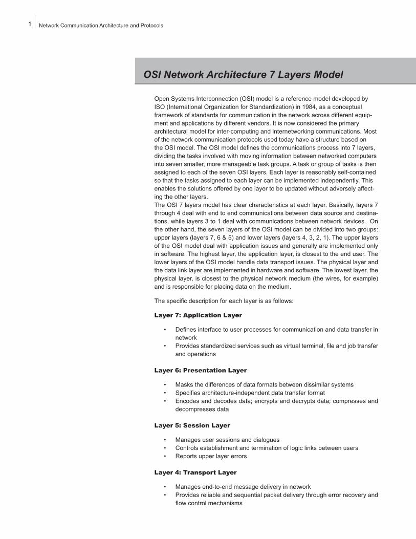
Open Systems Interconnection (OSI) model is a reference model developed by ISO (International Organization for Standardization) in 1984, as a conceptual framework of standards for communication in the network across different equip-ment and applications by different vendors. It is now considered the primary architectural model for inter-computing and internetworking communications. Most of the network communication protocols used today have a structure based on the OSI model. The OSI model defines the communications process into 7 layers, dividing the tasks involved with moving information between networked computers into seven smaller, more manageable task groups. A task or group of tasks is then assigned to each of the seven OSI layers. Each layer is reasonably self-contained so that the tasks assigned to each layer can be implemented independently. This enables the solutions offered by one layer to be updated without adversely affect-ing the other layers. The OSI 7 layers model has clear characteristics at each layer. Basically, layers 7 through 4 deal with end to end communications between data source and destina-tions, while layers 3 to 1 deal with communications between network devices. On the other hand, the seven layers of the OSI model can be divided into two groups: upper layers (layers 7, 6 & 5) and lower layers (layers 4, 3, 2, 1). The upper layers of the OSI model deal with application issues and generally are implemented only in software. The highest layer, the application layer, is closest to the end user. The lower layers of the OSI model handle data transport issues. The physical layer and the data link layer are implemented in hardware and software. The lowest layer, the physical layer, is closest to the physical network medium (the wires, for example) and is responsible for placing data on the medium.
The specific description for each layer is as follows:
Layer 7: Application Layer
• Defines interface to user processes for communication and data transfer in network
• Provides standardized services such as virtual terminal, file and job transfer and operations
Layer 6: Presentation Layer
• Masks the differences of data formats between dissimilar systems• Specifies architecture-independent data transfer format• Encodes and decodes data; encrypts and decrypts data; compresses and
decompresses data
Layer 5: Session Layer
• Manages user sessions and dialogues• Controls establishment and termination of logic links between users• Reports upper layer errors
Layer 4: Transport Layer
• Manages end-to-end message delivery in network• Provides reliable and sequential packet delivery through error recovery and
flow control mechanisms
OSI Network Architecture 7 Layers Model

2 Network Communication Architecture and Protocols
• Provides connectionless oriented packet delivery
Layer 3: Network Layer
• Determines how data are transferred between net-work devices
• Routes packets according to unique network device addresses
• Provides fl ow and congestion control to prevent net-work resource depletion
Layer 2: Data Link Layer
• Defi nes procedures for operating the communication links
• Frames packets• Detects and corrects packets transmit errors
Layer 1: Physical Layer
• Defi nes physical means of sending data over network devices
• Interfaces between network medium and devices• Defi nes optical, electrical and mechanical characteris-
tics
Information being transferred from a software application in one computer to an application in another proceeds through the OSI layers. For example, if a software application in com-puter A has information to pass to a software application in computer B, the application program in computer A need to pass the information to the application layer (Layer 7) of com-puter A, which then passes the information to the presenta-tion layer (Layer 6), which relays the data to the session layer (Layer 5), and so on all the way down to the physical layer (Layer 1). At the physical layer, the data is placed on the phys-ical network medium and is sent across the medium to com-puter B. The physical layer of computer B receives the data from the physical medium, and then its physical layer passes the information up to the data link layer (Layer 2), which relays it to the network layer (Layer 3), and so on, until it reaches the application layer (Layer 7) of computer B. Finally, the ap-plication layer of computer B passes the information to the recipient application program to complete the communication process. The following diagram illustrated this process.
The seven OSI layers use various forms of control informa-tion to communicate with their peer layers in other computer systems. This control information consists of specifi c requests and instructions that are exchanged between peer OSI layers. Headers and Trailers of data at each layer are the two basic forms to carry the control information.
Headers are prepended to data that has been passed down from upper layers. Trailers are appended to data that has been passed down from upper layers. An OSI layer is not required to attach a header or a trailer to data from upper layers.
Figure 1-1: Communication between computers in a network
Each layer may add a Header and a Trailer to its Data, which consists of the upper layer’s Header, Trailer and Data as it proceeds through the layers. The Headers contain informa-tion that specifi cally addresses layer-to-layer communication. Headers, trailers and data are relative concepts, depending on the layer that analyzes the information unit. For example, the Transport Header (TH) contains information that only the Transport layer sees. All other layers below the Transport layer pass the Transport Header as part of their Data. At the network layer, an information unit consists of a Layer 3 header (NH) and data.
At the data link layer, however, all the information passed down by the network layer (the Layer 3 header and the data) is treated as data. In other words, the data portion of an infor-mation unit at a given OSI layer potentially can contain head-ers, trailers, and data from all the higher layers. This is known as encapsulation.
Figure 1-2: Data encapsulation at each layer
For example, if computer A has data from a software appli-cation to send to computer B, the data is passed to the ap-plication layer. The application layer in computer A then com-municates any control information required by the application layer in computer B by prepending a header to the data. The resulting message unit, which includes a header, the data and maybe a trailer, is passed to the presentation layer, which pre-
Application
Presentation
Session
Transport
Networt
Data Link
Physical
Application
Presentation
Session
Transport
Networt
Data Link
Physical
Application
Presentation
Session
Transport
Networt
Data Link
Physical
Application
Presentation
Session
Transport
Networt
Data Link
Physical
AH
PH
SH
TH
Data
Data
Data
Data
Data
Data
Data
NH
DH
AT
PT
ST
TT
NT
DT
OSI Network Architecture 7 Layers Model

3 Network Communication Architecture and Protocols
pends its own header containing control information intended for the presentation layer in computer B. The message unit grows in size as each layer prepends its own header and trail-er containing control information to be used by its peer layer in computer B. At the physical layer, the entire information unit is transmitted through the network medium.
The physical layer in computer B receives the information unit and passes it to the data link layer. The data link layer in com-puter B then reads the control information contained in the header prepended by the data link layer in computer A. The header and the trailer are then removed, and the remainder of the information unit is passed to the network layer. Each layer performs the same actions: The layer reads the header and trailer from its peer layer, strips it off, and passes the remain-ing information unit to the next higher layer. After the applica-tion layer performs these actions, the data is passed to the re-cipient software application in computer B, in exactly the form in which it was transmitted by the application in computer A.
One OSI layer communicates with another layer to make use of the services provided by the second layer. The services pro-vided by adjacent layers help a given OSI layer communicate with its peer layer in other computer systems. A given layer in the OSI model generally communicates with three other OSI layers: the layer directly above it, the layer directly below it and its peer layer in other networked computer systems. The data link layer in computer A, for example, communicates with the network layer of computer A, the physical layer of com-puter A and the data link layer in computer B. The following chart illustrates this example.
Figure 1-3: Data communication between peer layers
Application
Presentation
Session
Transport
Networt
Data Link
Physical
Application
Presentation
Session
Transport
Networt
Data Link
Physical
OSI Network Architecture 7 Layers Model

4 Network Communication Architecture and Protocols
TCP/IP architecture does not exactly follow the OSI model. Unfortunately, there is no universal agreement regarding how to describe TCP/IP with a layered model. It is generally agreed that TCP/IP has fewer levels (from three to five layers) than the seven layers of the OSI model. We adopt a four layers model for the TCP/IP architecture.
TCP/IP architecture omits some features found under the OSI model, combines the features of some adjacent OSI layers and splits other layers apart. The 4-layer structure of TCP/IP is built as information is passed down from applications to the physical network layer. When data is sent, each layer treats all of the information it receives from the upper layer as data, adds control information (header) to the front of that data and then pass it to the lower layer. When data is received, the opposite procedure takes place as each layer processes and removes its header before passing the data to the upper layer.
The TCP/IP 4-layer model and the key functions of each layer is described below:
Application Layer
The Application Layer in TCP/IP groups the functions of OSI Application, Presenta-tion Layer and Session Layer. Therefore any process above the transport layer is called an Application in the TCP/IP architecture. In TCP/IP socket and port are used to describe the path over which applications communicate. Most application level protocols are associated with one or more port number.
Transport Layer
In TCP/IP architecture, there are two Transport Layer protocols. The Transmission Control Protocol (TCP) guarantees information transmission. The User Datagram Protocol (UDP) transports datagram swithout end-to-end reliability checking. Both protocols are useful for different applications.
Network Layer
The Internet Protocol (IP) is the primary protocol in the TCP/IP Network Layer. All upper and lower layer communications must travel through IP as they are passed through the TCP/IP protocol stack. In addition, there are many supporting protocols in the Network Layer, such as ICMP, to facilitate and manage the routing process.
Network Access Layer
In the TCP/IP architecture, the Data Link Layer and Physical Layer are normally grouped together to become the Network Access layer. TCP/IP makes use of ex-isting Data Link and Physical Layer standards rather than defining its own. Many RFCs describe how IP utilizes and interfaces with the existing data link protocols such as Ethernet, Token Ring, FDDI, HSSI, and ATM. The physical layer, which defines the hardware communication properties, is not often directly interfaced with the TCP/IP protocols in the network layer and above.
TCP/IP Four Layers Architecture Model

5 Network Communication Architecture and Protocols
Figure 1-4: TCP/IP Protocol Stack 4 Layer Model
In this book, however, we present TCP/IP protocols into the OSI 7 layers structure for comparison purpose.
Application Layer (Telnet, Ftp, SMTP ...)
Data
Transport Layer (TCP, UDP ...)
DataHeader
Network Layer (IP ...)
Header DataHeader
Network Access Layer (Ethernet, Token Ring ...)
Header DataHeaderHeader
TCP/IP Four Layers Architecture Model
6 Protocols Guide TCP/IP - Application Layer Protocols
Application Layer ProtocolsProtocol Name
BOOTP: Bootstrap Protocol
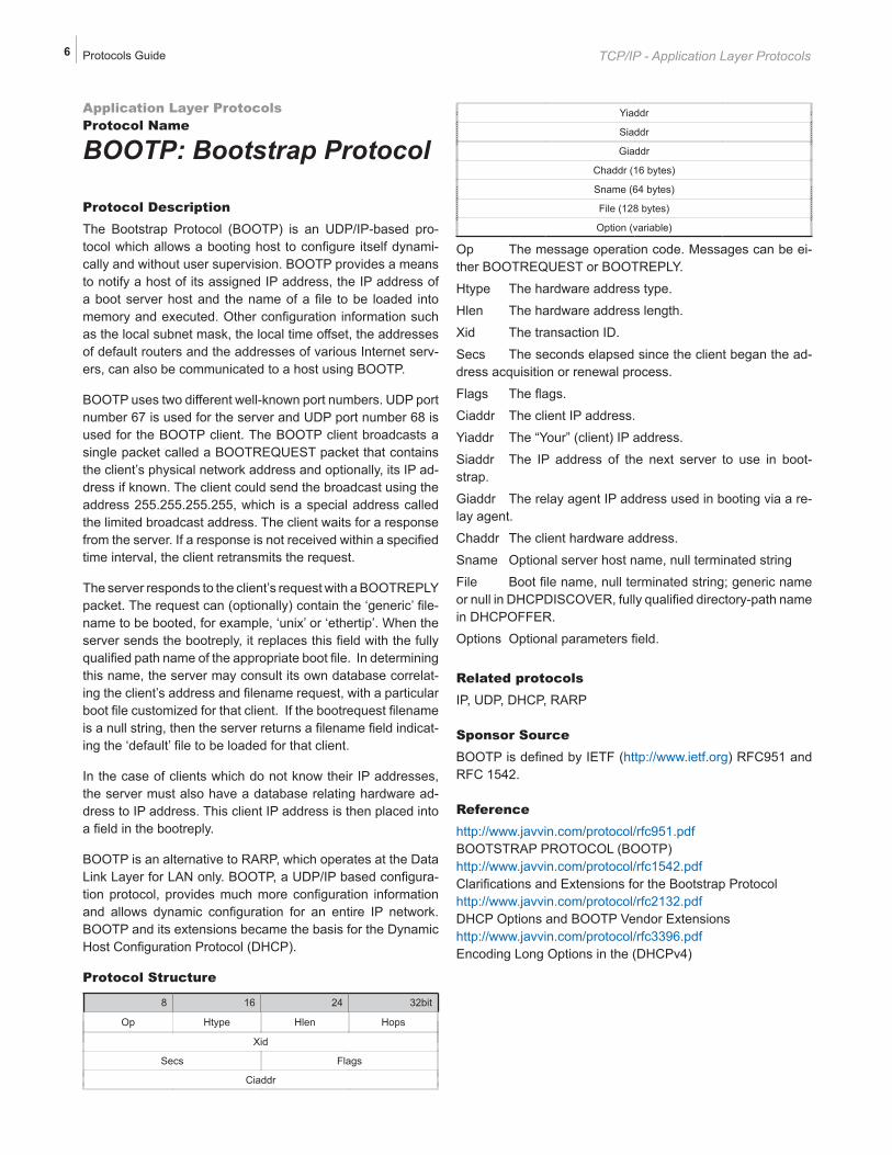
Protocol DescriptionThe Bootstrap Protocol (BOOTP) is an UDP/IP-based pro-tocol which allows a booting host to configure itself dynami-cally and without user supervision. BOOTP provides a means to notify a host of its assigned IP address, the IP address of a boot server host and the name of a file to be loaded into memory and executed. Other configuration information such as the local subnet mask, the local time offset, the addresses of default routers and the addresses of various Internet serv-ers, can also be communicated to a host using BOOTP.
BOOTP uses two different well-known port numbers. UDP port number 67 is used for the server and UDP port number 68 is used for the BOOTP client. The BOOTP client broadcasts a single packet called a BOOTREQUEST packet that contains the client’s physical network address and optionally, its IP ad-dress if known. The client could send the broadcast using the address 255.255.255.255, which is a special address called the limited broadcast address. The client waits for a response from the server. If a response is not received within a specified time interval, the client retransmits the request.
The server responds to the client’s request with a BOOTREPLY packet. The request can (optionally) contain the ‘generic’ file-name to be booted, for example, ‘unix’ or ‘ethertip’. When the server sends the bootreply, it replaces this field with the fully qualified path name of the appropriate boot file. In determining this name, the server may consult its own database correlat-ing the client’s address and filename request, with a particular boot file customized for that client. If the bootrequest filename is a null string, then the server returns a filename field indicat-ing the ‘default’ file to be loaded for that client.
In the case of clients which do not know their IP addresses, the server must also have a database relating hardware ad-dress to IP address. This client IP address is then placed into a field in the bootreply.
BOOTP is an alternative to RARP, which operates at the Data Link Layer for LAN only. BOOTP, a UDP/IP based configura-tion protocol, provides much more configuration information and allows dynamic configuration for an entire IP network. BOOTP and its extensions became the basis for the Dynamic Host Configuration Protocol (DHCP).
Protocol Structure
8 16 24 32bit
Op Htype Hlen Hops
Xid
Secs Flags
Ciaddr
Yiaddr
Siaddr
Giaddr
Chaddr (16 bytes)
Sname (64 bytes)
File (128 bytes)
Option (variable)
Op The message operation code. Messages can be ei-ther BOOTREQUEST or BOOTREPLY.
Htype The hardware address type.
Hlen The hardware address length.
Xid The transaction ID.
Secs The seconds elapsed since the client began the ad-dress acquisition or renewal process.
Flags The flags.
Ciaddr The client IP address.
Yiaddr The “Your” (client) IP address.
Siaddr The IP address of the next server to use in boot-strap.
Giaddr The relay agent IP address used in booting via a re-lay agent.
Chaddr The client hardware address.
Sname Optional server host name, null terminated string
File Boot file name, null terminated string; generic name or null in DHCPDISCOVER, fully qualified directory-path name in DHCPOFFER.
Options Optional parameters field.
Related protocolsIP, UDP, DHCP, RARP
Sponsor SourceBOOTP is defined by IETF (http://www.ietf.org) RFC951 and RFC 1542.
Referencehttp://www.javvin.com/protocol/rfc951.pdf BOOTSTRAP PROTOCOL (BOOTP)http://www.javvin.com/protocol/rfc1542.pdfClarifications and Extensions for the Bootstrap Protocolhttp://www.javvin.com/protocol/rfc2132.pdfDHCP Options and BOOTP Vendor Extensionshttp://www.javvin.com/protocol/rfc3396.pdfEncoding Long Options in the (DHCPv4)
7 Protocols Guide TCP/IP - Network Layer Protocols
MPLS ProtocalsProtocol Name
MPLS: Multiprotocol Label SwitchingProtocol DescriptionMultiprotocol Label Switching (MPLS) is an architecture for fast packet switching and routing, which operates independent of the layer 2 and layer 3 protocols. MPLS provides a means to map IP addresses to simple, fixed-length labels used by different packet-forwarding and packet-switching technolo-gies. It interfaces to existing routing and switching protocols, such as IP, ATM, Frame Relay, PPP and Ethernet. High-speed switching of data using MPLS is possible because the fixed-length labels are inserted at the very beginning of the packet or cell and can be used by hardware to switch packets quickly between links.In MPLS, data transmission occurs on Label-Switched Paths (LSPs). LSPs are virtual tunnels, that are formed by a sequence of labels at each and every node along the path from the source to the destination. Martini proposed “two-label” approach in which two labels are prepended at the ingress Label Switch Router (LSR) to carry Protocol Data Unit (PDU) forward across the entire MPLS network and finally re-moved at the engress LSR. The first label, called a Tunnel La-bel, decides which LSP will be used to get packets from the in-gress LSR to the engress LSR. The second label, called a VC Label, provides Layer 2 forwarding information at egress LSR. Martini method is the most popular way for encapsulating of layer 2 protocols such as Frame Relay, ATM, or Ethernet.
MPLS utilizes existing IP routing protocols such as Border Gateway Protocol (BGP), Resource ReSerVation Protocol (RSVP) and Open Shortest Path First (OSPF), etc. MPLS has also defined a new set of protocols such as LDP, CR-LDP, RSVP-TE for more effective signaling and routing. The indus-try is developing more new standards such as VPLS, HVPLS and GMPLS, to fully extend its capabilities,
MPLS has mechanisms to manage traffic flows of various granularities for the purpose of traffic management and QoS. Specifically, MPLS provide a rich set of traffic management capabilities in the areas of traffic policing, congestion man-agement, traffic shapping and priority queuing.
In summary, MPLS is designed to address many current net-work problems such as networks speed, scalability, quality of service (QoS) management and traffic engineering. With its powerful new features and abilities to interface with legacy technologies, MPLS has become a solution for the next gen-eration backbone networks for multiple services such as data, voice and video over the same network.
Generalized MPLS (GMPLS), a newer standard, extends the MPLS capabilities to cover multiple underlay traffic technolo-gies such as TDM, FDM, Fiber, Optical etc. with better man-agement and provisioning schemes. In this section, we focus
on the MPLS framework. Other protocols in the MPLS suite and GMPLS will be discussed in separate documents.
Protocol StructureMPLS label structure:
20 23 24 32bit
Label Exp S TTL
• Label - Label Value carries the actual value of the Label. When a labeled packet is received, the label value at the top of the stack is looked up and the system learns:
a) the next hop to which the packet is to be forwarded;
b) the operation to be performed on the la-bel stack before forwarding; this opera-tion may be to replace the top label stack entry with another, or to pop an entry off the label stack, or to replace the top label stack entry and then to push one or more additional entries on the label stack.
• Exp - Experimental Use: Reserved for experimen-tal use.
• S - Bottom of Stack: This bit is set to one for the last entry in the label stack, and zero for all other label stack entries
• TTL - Time to Live field is used to encode a time-to-live value.
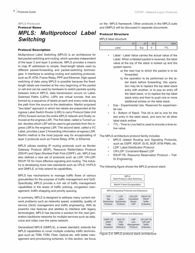
The MPLS architecture protocol family includes:• MPLS related Routing and Signaling Protocols,
such as OSPF, RSVP, IS-IS, BGP, ATM PNNI, etc.• LDP: Label Distribution Protocol. • CR-LDP: Constraint-Based LDP• RSVP-TE: Resource Reservation Protocol – Traf-
fic Engineering
The following figure shows the MPLS protocol stack:
Figure 2-4: MPLS protocol stack architecture
MPLSMulti-Protocol Label Switching
Martini Frame Encapaulation
MPLS Singnaling Protocols and Extensions
TDPTag
DistributionProtocol
LDPLabel
DistributionProtocol
CR-LDPConstraint
BoardLDP
LDPLabel
DistributionProtocol
RSVP-TERSVPTarffic
Entention
GMPLS Protocols and Extensions
OSPF-TEOSPFTraffic
Entention
LDPLabel
DistributionProtocol
LMPLink
ManogamentProtocol
ISIS-TEISIS
TrafficEntention
CR-LDP-TECR-LDPTarffic
Entention

8 Protocols Guide TCP/IP - Network Layer Protocols
The structure of each protocol will be discussed in separate documents.
Related protocolsLDP, CR-LDP, RSVP-TE, IP, ATM, RSVP, OSPF, GMPLS
Sponsor SourceMPLS is defined by IETF (http://www.ietf.org) RFC3031 and RFC 3032.
Referencehttp://www.javvin.com/protocol/rfc3031.pdfMultiprotocol Label Switching Architecture http://www.javvin.com/protocol/rfc3032.pdfMPLS Label Stack Encodinghttp://www.javvin.com/protocol/rfc3443.pdfTime To Live (TTL) Processing in Multi-Protocol Label Switch-ing (MPLS) Networkshttp://www.javvin.com/protocol/rfc3036.pdfLDP Specification http://www.javvin.com/protocol/rfc3209.pdfRSVP-TE: Extensions to RSVP for LSP Tunnelshttp://www.javvin.com/protocol/rfc3212.pdfConstraint-Based LSP Setup using LDPhttp://www.javvin.com/protocol/rfc3213.pdfApplicability Statement for CR-LDPhttp://www.faqs.org/ftp/pub/internet-drafts/draft-martini-l2circuit-encap-mpls-08.txt Encapsulation Methods for Transport of Layer 2 Frames Over IP and MPLS Networks
9 Appendix
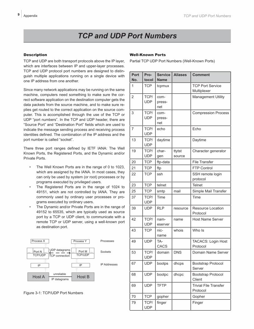
DescriptionTCP and UDP are both transport protocols above the IP layer, which are interfaces between IP and upper-layer processes. TCP and UDP protocol port numbers are designed to distin-guish multiple applications running on a single device with one IP address from one another.
Since many network applications may be running on the same machine, computers need something to make sure the cor-rect software application on the destination computer gets the data packets from the source machine, and to make sure re-plies get routed to the correct application on the source com-puter. This is accomplished through the use of the TCP or UDP “port numbers”. In the TCP and UDP header, there are “Source Port” and “Destination Port” fields which are used to indicate the message sending process and receiving process identities defined. The combination of the IP address and the port number is called “socket”.
There three port ranges defined by IETF IANA: The Well Known Ports, the Registered Ports, and the Dynamic and/or Private Ports.
• The Well Known Ports are in the range of 0 to 1023, which are assigned by the IANA. In most cases, they can only be used by system (or root) processes or by programs executed by privileged users.
• The Registered Ports are in the range of 1024 to 49151, which are not controlled by IANA. They are commonly used by ordinary user processes or pro-grams executed by ordinary users.
• The Dynamic and/or Private Ports are in the range of 49152 to 65535, which are typically used as source port by a TCP or UDP client, to communicate with a remote TCP or UDP server, using a well-known port as destination port.
Figure 3-1: TCP/UDP Port Numbers
Well-Known PortsPartial TCP UDP Port Numbers (Well-Known Ports)
Port No.
Pro-tocol
Service Name
Aliases Comment
1 TCP tcpmux TCP Port Service Multiplexer
2 TCP/UDP
com-press-net
Management Utility
3 TCP/UDP
com-press-net
Compression Process
7 TCP/UDP
echo Echo
13 TCP/UDP
daytime Daytime
19 TCP/UDP
char-gen
ttytst source
Character generator
20 TCP ftp-data File Transfer21 TCP ftp FTP Control22 TCP ssh SSH remote login
protocol23 TCP telnet Telnet25 TCP smtp mail Simple Mail Transfer37 TCP/
UDPTime Time
39 UDP RLP resource Resource Location Protocol
42 TCP/UDP
nam-eserver
name Host Name Server
43 TCP nic-name
whois Who Is
49 UDP TA-CACS
TACACS: Login Host Protocol
53 TCP/UDP
domain DNS Domain Name Server
67 UDP bootps dhcps Bootstrap Protocol Server
68 UDP bootpc dhcpc Bootstrap Protocol Client
69 UDP TFTP Trivial File Transfer Protocol
70 TCP gopher Gopher79 TCP/
UDPfinger Finger
TCP and UDP Port Numbers
TCP and UDP Port Numbers
Process X
... Port N ...TCP/UDP
IP
Host A
Process Y
... Port M ...TCP/UDP
IP
Host B
Processes
Sockets
IP Addresses
unreliable
IP datagrams
UDP datagrams
TCP connection

“This book is an excellent reference for Internet programmers, network profession-als and college students who are majoring IT and networking technologies. It is also useful for any individuals who want to know more details about Internet technologies. I highly recommend this book to our readers.”
Dr. Ke YanChief Architect of Juniper Networks
Founder of NetScreen Technologies
Fully explains and illustrates all commonly used network communication protocols, including TCP/IP, WAN, LAN technologies
Covers the latest and emerging technologies such as VOIP, SAN, MAN, VPN/Security,WLAN, VLAN and more
Addresses vendor specifi c technologies: Cisco, IBM, Novell, Sun, HP, Microsoft, Apple,etc.
Reviews the ISO networking architecture and protocols
Covers SS7 protocols
Hundreds of illustrations of protocol formats and header structures
Hundreds of references for further reading and studies
“Must-Have” for IT/Networking professionals and students
Javvin Technologies, Inc.
13485 Old Oak WaySaratoga CA 95070 USA
www.javvin.com
Network Protocols HandbookThird Edition