Embed Size (px)
Citation preview

Network Protector Instruction Manual
Type 147NP
2250 to 4500 Amperes
ichards MANUFACTURING COMPANY, SALES, INC. 517 LYONS AVENUE, IRVINGTON, NJ 07111 Phone 973-371-1771 Fax 973-371-9538
IM 1225-001B


i
DISCLAIMER OF WARRANTIES AND LIMITATION OF LIABILITY
All equipment or component parts manufactured or distributed by Richards Mfg. Co.,
Sales Inc. are expressly warranted by Richards to be free from defect in workmanship or material when subjected to normal and proper use. Said warranty shall be for a period of one (1) year from the date of installation of such equipment not to exceed eighteen (18) months from the date of shipment of such equipment. Notice of any claim arising out of this warranty shall be made in writing within the warranty period. Richards’ sole liability and buyer’s sole remedy under this warranty shall be limited to the repair or replacement, FOB factory, of any equipment or part determined to be defective in either material or workmanship. This warranty does not apply to any equipment, part or component requiring repair or replacement due to improper use or when determined to have been subjected to abnormal operating conditions or in the event of buyer’s failure to follow normal maintenance procedures. No warranty or guarantee expressed or implied, including any warranty or representation as to the design, operation, merchantability or fitness for any purpose is made other than those expressly set forth above which are made in lieu of any and all warranties or guarantees. Richards Mfg. Co. shall not be liable for any loss or damage, directly or indirectly, arising out of the use of equipment or parts (including software) or for any consequential damages, including but not limited to, any claims for buyer’s lost profits or for any claim or demand against the buyer by a third party. Richards Mfg. Co. assumes no responsibility for any damage or loss resulting from the use of this manual. Information in this document is subject to change without notice.
ii
SAFETY INFORMATION
This manual is intended for use by qualified individuals responsible for the installation, maintenance and operation of network protectors. Potentially unsafe conditions exist when installing, maintaining or operating network protectors. All applicable safety procedures should be adhered to when installing, maintaining, or operating network protectors. Only qualified electrical personnel should be permitted to work on 147NP Network Protectors. De-energized and rack out the network protector mechanism before any maintenance procedure. Never defeat safety interlocks on the network protector. Never energize a partially assembled network protector. Use extreme caution when installing or working on an energized protector. Use insulated tools and gloves when working on energized network protectors. Perform all appropriate electrical tests before any installation or operation of the network protectors.
WARNING
Before unpacking, installing, servicing, or operating 147NP network protectors read this manual thoroughly. For additional information, contact Richards Mfg. Co. directly. For application information, consult Richards Mfg. Co. or see appropriate ANSI Standards. Do not operate 147NP network protectors under load except in appropriate enclosures. The Richards 147NP Network Protectors are designed for secondary network application at 125/216 volt and 277/480 volt wye connected systems. Do not exceed design ratings.
iii
iv
TABLE OF CONTENTS PAGE I. OVERVIEW 1
A. Introduction 1 II. INSTALLATION 1
A. Receiving, Handling and Storage 1 B. Removing the Breaker Unit 2 C. Connections 3 D. Relay Installation 4
III. MAINTENANCE 4
A. Schedule 4 IV. INSPECTION 5
A. Mechanical Inspection 5 B. Wiring 6
C. Auxiliary Switch and Control Switch 6 D. Permissive Switch 6
E. Shunt Trip 6 F. Gear Reduction Unit 6
V. ELECTRICAL OPERATION TESTS 7
A. Units Rated 125/216 Volts 7 B. Units Rated 277/480 Volts 7 C. Units Mounted on D-10 and D-12 Frames 7 D. Test Procedure 7 E. Testing Network Relays 9
VI. THE REMOVABLE UNIT 10 A. Separation of the Unit Assemblies 10 B. Inner Operating Mechanism 13 C. Closing 15 D. Opening 15
E. Mechanism Adjustments 16 F. Replacement of Mechanism Components 17 G. Base and Pole Unit Assembly 18
v
H. Arc Quenchers 18 I. Phase Barriers 18
J. Pole Unit Assembly 18 K. Adjustment of Contact Wipe and Alignment 20 L. Replacing Specific Components 23
VII. ELECTRICAL DEVICES AND CONTROL 25
A. Auxiliary Switch and Operation Counter 25 B. Permissive Switch 26 C. Motor Control Relay 27 D. Trip Circuit Relay 28 E. Control Switch 28 F. Shunt Trip Device 29
VIII. RENEWAL PARTS 30 IX. DIAGRAMS
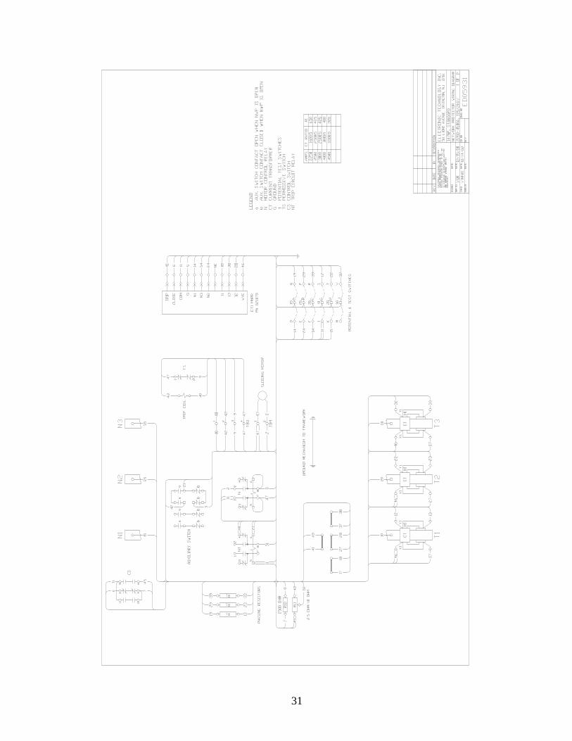
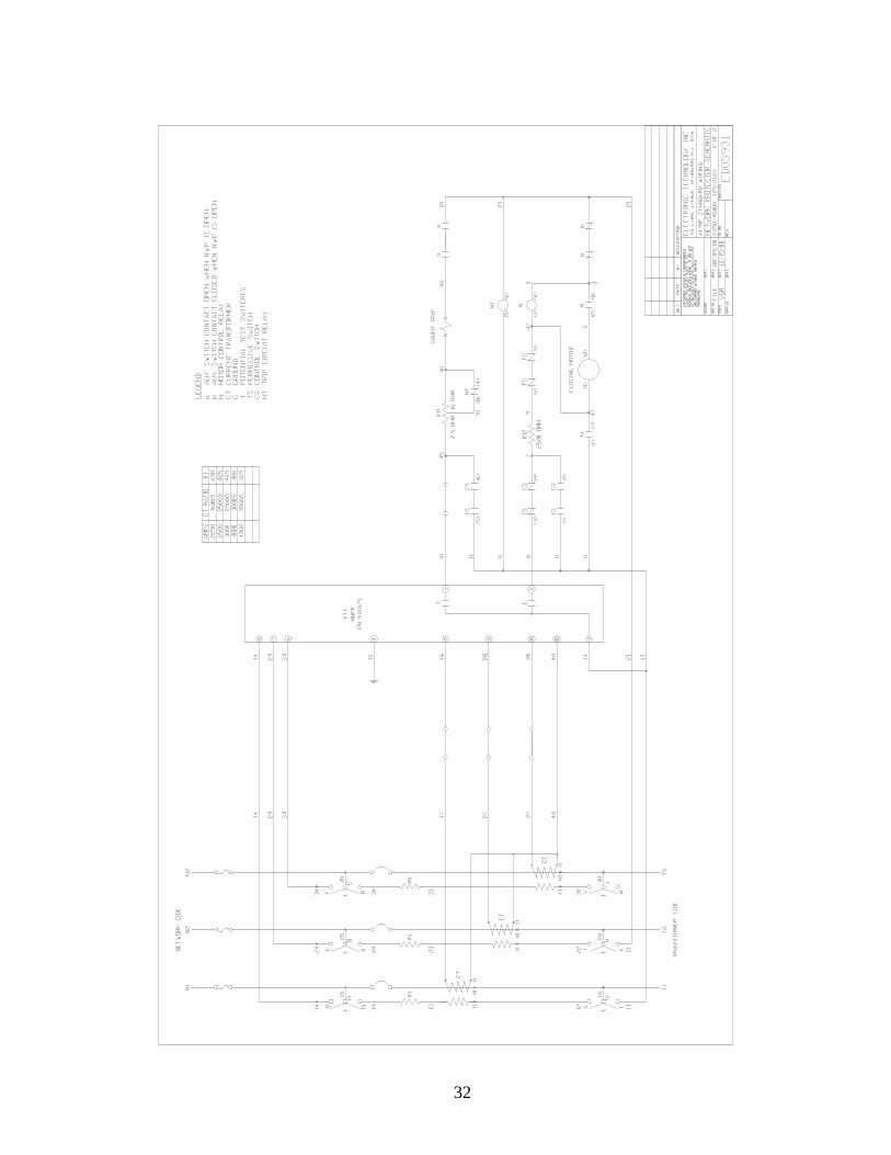
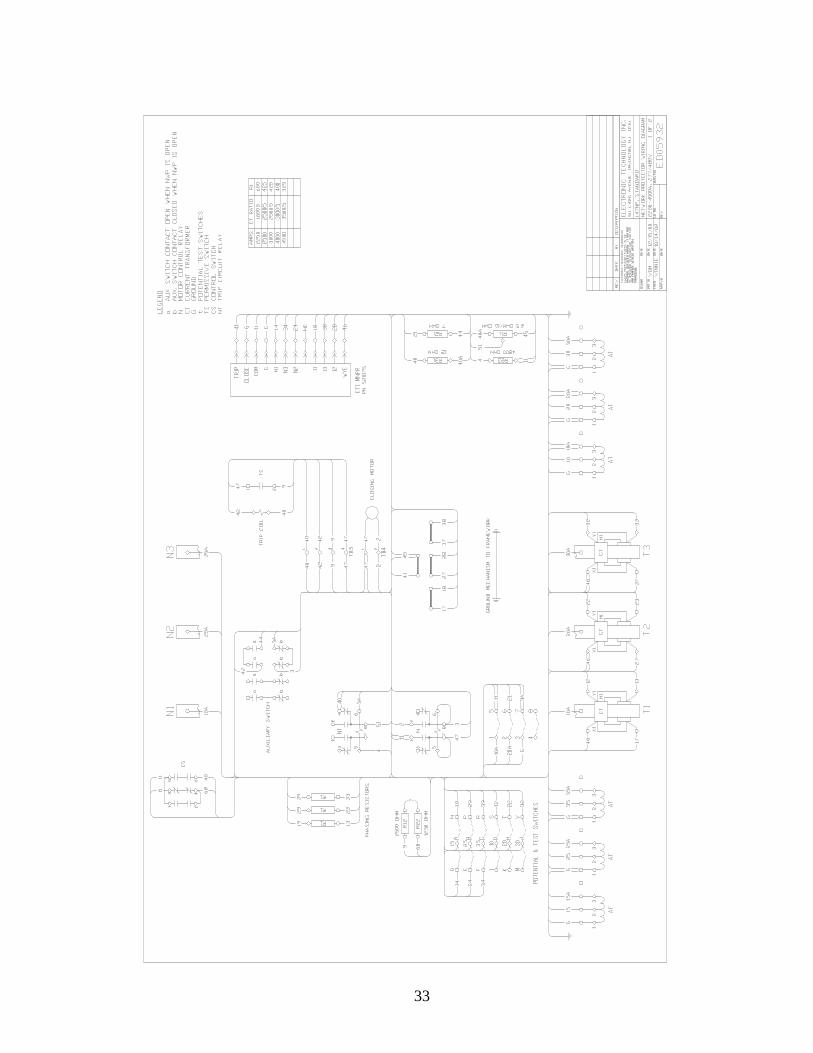
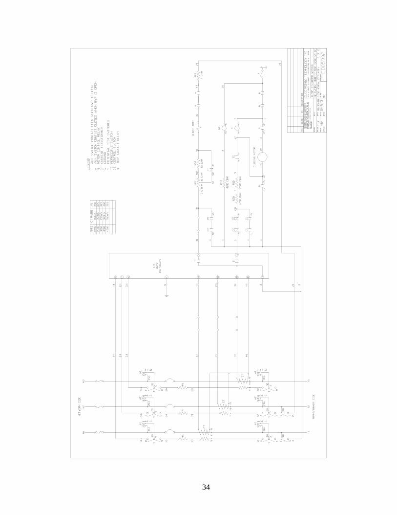
A. Wiring Diagram, 125/216 Volt Protectors 31 B. Schematic Diagram, 125/216 Volt Protectors 32 C. Wiring Diagram, 277/480 Volt Protectors 33 D. Schematic Diagram, 277/480 Volt Protectors 34

vi
1
I. OVERVIEW A. Introduction
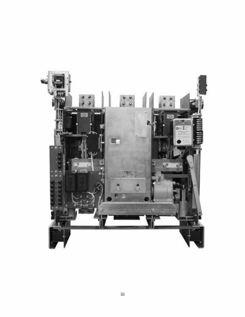
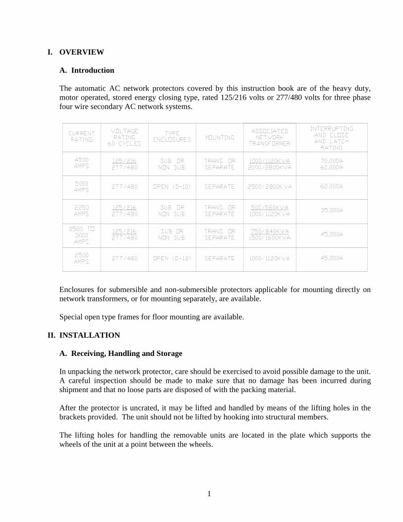
The automatic AC network protectors covered by this instruction book are of the heavy duty, motor operated, stored energy closing type, rated 125/216 volts or 277/480 volts for three phase four wire secondary AC network systems.
Enclosures for submersible and non-submersible protectors applicable for mounting directly on network transformers, or for mounting separately, are available.
Special open type frames for floor mounting are available. II. INSTALLATION
A. Receiving, Handling and Storage
In unpacking the network protector, care should be exercised to avoid possible damage to the unit. A careful inspection should be made to make sure that no damage has been incurred during shipment and that no loose parts are disposed of with the packing material.
After the protector is uncrated, it may be lifted and handled by means of the lifting holes in the brackets provided. The unit should not be lifted by hooking into structural members.
The lifting holes for handling the removable units are located in the plate which supports the wheels of the unit at a point between the wheels.
2
Slings with spreaders or some other means of providing a straight upward force in lifting are recommended in the handling of this equipment.
If the protectors are not to be used for some time, they may be stored uncrated or in the crates in which they are shipped in an upright position in a clean, dry storage area. It would be well to provide a covering against the accumulation of dust, but it should not be of a material that will promote the collection of moisture due to condensation. A paper covering that allows free ventilation is satisfactory. Before installation, remove small plug screw from top of reduction gear unit assembly and replace with vent provided.
When the network protector is installed, whether in its permanent location or in a temporary one for testing, it should be placed in an upright position on a straight level foundation. Before any attempt is made to roll out the removable unit, it is very important that the enclosing case be securely fastened to a wall or supporting framework. B. Removing the Breaker Unit
1. Turn control switch handle to the “Trip” position. The breaker should be in the open
position with the closing spring pinned.
2. Remove fuses or “dummy” fuses consisting of wooden blocks. 3. Remove disconnects or shunts from other end of each pole of the breaker.
4. Mount the two rollout rails by inserting their square ends through the elongated slots in the
back frame of the enclosure and then, while holding the rails horizontally, fastened them to the front vertical members of the enclosure frame by means of the flat head screws provided for this purpose. On newer designs the rails simply insert into a stationary supporting structure within the housing. On D-10 and D-12 stationary units, the rollout rails are inserted into the front ends of the angles which form the upper side members of the stationary frame. A steel pin, provided for the purpose, is then to be inserted, preventing the removable part of the rail from pulling out as the removable breaker unit is rolled forward.
5. Unfasten the four captive hex head bolts (two on each side of the breaker unit frame) that
secure the removable breaker unit to the stationary unit.
6. The unit now may be rolled forward on the rails. Replacement of the unit is accomplished by reversing the procedure.

3
C. Connections Cable or bus connections should be made to the protector with the breaker unit open and with the network protector fuses removed. It may prove to be more convenient to take out the removable unit before the enclosure is mounted and the connections are made. If this is done, however, the case must be temporarily secured to keep it from tipping over when the removable unit is rolled forward on its rails. After the unit is replaced, the fuses should not be installed until after the protector has been thoroughly inspected and tested, if this has not been done previously. Just before making the connections to the protector terminals, it would be well to clean the contact surfaces with a fine brass wire brush. A clean, dry cloth should then be used to remove the resulting loose material.
1. Manual Trip Button 2. Rollout Rails 3. Trip Circuit Relay 4. Motor Control 5. Phasing Relay Plug 6. Master Relay Plug 7. Control Switch 8. Ammeter Jack
Figure 1 - 4500 Ampere Unit in Submersible Enclosure 9. Secondary Disconnect Device
10. Fuses 11. Potential and test Switches 12. External Operating Handle with Provision for Padlocking 13. Polyester Bushings 14. Counter and Semaphore 15. Viewing Ports 16. Manual Close Shaft
4
D. Relay Installation The relays may be shipped with the unit or in separate cartons. If shipped mounted, they should always be removed from the protector when handling the breaker unit. To install the relay, unscrew the knurled thumbscrew, move the claw-shaped cam counterclockwise and then place the relay in position, making sure that the contact blades on the relay line up with the stationary contacts. Move the cam clockwise to jack the relay into position. Screw knurled thumb-screw down to secure the relay. The relays are now free to swing through a large angle. To fasten them in their operating positions, move the relay clockwise and pull latch forward. In removing the relays, care must be exercised to avoid dropping them. After the latch is released and the thumbscrew is unfastened, the relay should be manually supported before the claw-shaped cam is rotated. New network protectors are wired for microprocessor type relays unless otherwise specified.
III. MAINTENANCE A regular inspection and maintenance schedule for network protectors is recommended. While experience will best indicate the frequency with which inspection should be made, the following routine is suggested.
In all cases open the protector manually and lock in the open position first, then remove fuses and open the primary disconnects before working on, inspecting or testing protector.
A. Schedule
1. During Installation Complete inspection and test. See INSPECTION. 2. After First 24 Hours of Automatic Operation Read operation counter to make sure that the protector is not operating excessively. Additional load will eliminate a large percentage of the operations. If the number of operations during the first 24 hours is considered excessive, a check should be made to see that the mechanism operates positively. If it does, the protector is being operated by numerous power reversals. To correct this, system voltage and power angle should be checked and adjusted. 3. After First 48 Hours Again read operation counter. If the number of operations is normal, daily reading may be discontinued.
5
4. After First Week Read operation counter. 5. After First Month Read operation counter. 6. After First Six Months Complete inspection and test. 7. Yearly a. Remove breaker from enclosing case, inspect and check wipe, and clean contacts. b. Check wiring terminals for tightness. c. Check auxiliary switch. d. Check motor control relay and trip circuit relay contacts and clean if necessary. If any of these checks, or the protector and relay inspection and testing routine reveal faulty conditions, refer to the section of these instructions under THE REMOVABLE UNIT that deals with the component involved. Adjustment and replacement procedures will not be found.
IV. INSPECTION
Although the network protector is thoroughly inspected and tested at the factory, and shipped in a condition ready for installation, because of the considerable handling of the unit it is important that a pre-installation inspection and test be made. This may be done at a service shop or at the installation of unit. After the unit is put into service, it should be periodically inspected as recommended in the section on maintenance.
A. Mechanical Inspection With respect to mechanical inspection at installation, it should not be necessary to check all the adjustments that pertain to the various mechanical components of the unit. These have been carefully set at the factory and subjected to various checks. If the protector functions correctly, it may be safely assumed that they are correct. These adjustments are included in these instructions under the sections dealing with the components of the removable unit. However, they are intended primarily for use after the protector has been taken out of service for reconditioning. The mechanical operation of the protector breaker unit may be checked manually be means of the maintenance operating handle. This is a ratcheted lever the socket of which fits on an extension
6
of the gear reduction unit shaft. The breaker may be closed by this means and opened by operation of the trip button. In conjunction with this phase of pre-installation inspection, the following checks should be made. B. Wiring Wiring should be checked against the wiring diagram which relates to the particular protector involved. C. Auxiliary Switch and Control Switch The proper operation of these switches should be checked by means of a bell set against the open and closed positions of the breaker. D. Permissive Switch (Figure 5) The function of the permissive switch (24) is to ensure that the closing circuit will remain open when the unit is padlocked in the open position. The operation of this switch is mechanically tied in with the manual trip mechanism. When the trip button is depressed, the permissive switch is opened. Inserting a padlock shackle through the hole at the trip button renders the breaker mechanism trip free and keeps the permissive switch open. This feature may be checked with a bell set as far as the switch is concerned. Its mechanical aspect may be tested by operation of the maintenance closing handle. When this is operated, the closing springs will discharge, but the mechanism should be trip free. E. Shunt Trip (Figure 15) The mechanical operation of the shunt trip device may be checked by closing the device armature (9) against the magnet (6) with the breaker unit in the closed position. This may be done by moving the counterweight (4) in front of the device upwards. There should be some free movement of the armature before its striker (10) contacts the paddle on the trip magnet. In moving the armature with the breaker closed, keep hands clear of moving parts of the breaker. Use some convenient object of sufficient length to push upwards on the counterweight. If positive overtravel of the shunt trip armature is to be established, a 1/32 inch shim may be placed between armature and magnet. The breaker should then trip when the armature is closed. F. Gear Reduction Unit If the metal cap in the vent hole of the gear reduction unit has not already been replaced by the vent, this replacement should now be made.
7
V. ELECTRICAL OPERATION TESTS A. Units Rated 125/216 Volts
These may be tested in their normal positions or rolled out on rails. The fuse and primary disconnects or shunts should be removed. (On standard units the twelve insulated test caps may be removed and test connections made to the exposed studs.)
B. Units Rated 277/480 Volts
Standard units may be tested in their normal positions or rolled out on rails. The fuses and primary disconnects or shunts should be removed. (All the Insulated test caps may be removed and test connections made to the exposed studs.)
C. Units Mounted on D-10 and D-12 Frames (Figure 16)
Standard units may be tested in their normal positions or rolled forward on the rails. New units no longer include the limit switch assembly to change the operating voltage form 480 to 216 volts.
D. Test Procedure
1. Apply test voltage to phase 1 and 2 studs on transformer side of breaker contacts for to appropriate test studs. See paragraph A, B, and C and wiring diagram supplied with unit. (Typical wiring diagrams, Section IX)
2. The electrical operation of the protector may now be checked any desired number of times
by completing the control circuit. 3. Make the following tests:
a. Minimum Trip
On units rated 125/216 volts – 16 volts On units rated 277/480 volts – 36 volts
With the protector in the closed position, reduce the applied voltage to indicated value. When control switch is turned to “TRIP” the protector should open.
b. Minimum Motor Closing On units rated 125/216 volts – 157 volts On units rated 277/480 volts – (277 volt control) – 200 volts
Apply indicated voltage with the protector open. With the motor control relay contacts held closed (see Figure 14), complete the closing circuit. The motor should
8
close the protector. There is not adjustment for minimum motor closing voltage. The test indicates whether or not the motor has sufficient torque to operate the closing mechanism. If the motor is defective the protector will not close.
c. Motor Control Relay
On units rated 125/216 volts Never pick up – 166 volts Always pick up – 180 volts On units rated 277/480 (277 volt control) Never pick up – 212 volts Always pick up – 230 volts
The motor control relay should pick up at some point between “never pick up” and “always pick up” values of voltage. With the protector open apply “never pick up” voltage. Turn the control switch to close several times. The relay should not pick up. If it does, the relay should be adjusted to pick up at a higher value of voltage. This is done by increasing the air gap between the relay contacts (see Figure 14). The air gas can be varied by turning, in or out, the adjustment screw that acts as a stop for the relay contacts when the relay is open. Before this can be turned, its locknut must be loosened.
If the relay does not pick up at a “never pick up” volts, increase the applied voltage to “always pick up” volts. Again initiate closing by means of the control switch. The motor control relay should now pick up on every signal. If it does not, adjust by decreasing the relay contact air gap.
d. Open and close the protector several times by means of the control switch. While
doing so, observe the operation of the counter indicator on the front of the removable unit, making sure its functions properly.
It should be unnecessary to make high potential tests on protectors, because they are completely tested before leaving the factory. If, however, it is desired to make such tests, a potential of 2000 volts ac may be applied for 60 seconds from each main conductor to ground and between any two main conductors.
Caution: During such tests see that the motor leads are disconnected and that the Network relays, are removed from the protector. The motor may be tested at 900 volts ac 60 cycles, for 60 seconds, and the relays tested separately at 1500 volts ac for one second. After field service the hipot test values are 75 percent of factory tests values.
9
E. Testing Network Relays
To insure proper functioning of the network protector, the network relays should be periodically inspected and tested. This can be done in the laboratory and complete instructions for this method of testing are given in relay instruction for electromechanical relays and for microprocessor relays. A spare relay is recommended for use on the protector while laboratory test and adjustments are being made. Where laboratory testing facilities are not available or for other reasons it may be desirable to test the network relays in the field on the protector. These tests should be performed using a network protector test kit such as one manufactured by Multi-Amp. Explicit instructions are included with these test kits.
1. Electromechanical Relay Important – The correct operation of the electromechanical type network master relay depends upon the application to the relay coils of currents and the voltages of the proper phase sequence. For this reason the phase sequence of the network should be checked before putting a protector into service. This can be done by making a temporary reconnection of the phasing relay and observing its operation as follows: a. Make the temporary change in the wiring of the phasing relay as indicated on the wiring diagram for the network protector. b. All test caps removed except test caps. P, R, and F. c. Trip protector open and move control switch to “TRIP” position. Do not close protector during this test. d. Connect the network side of the protector to the network. e. Observe the operation of the phasing relay contacts. If the phasing relay contacts close with a strong torque toward the right, the phase sequence is 1, 2, 3. If the phasing relay contacts open or move to the left, the phase sequence is 3, 2, 1. The phase sequence of the protector is determined by the lead connections as shown on the wiring diagram. In general network protectors are wired for 1, 2, 3 phase sequence at the factory. Protectors may be obtained which are wired for 3, 2, 1 phase sequence if desired. (Note: Protectors wired for 1, 2, 3 phase sequence may be used with a 3, 2, 1 phase sequence provided four leads are interchanged in accordance with Note 1 on the wiring diagram and vice versa). f. Return the phasing relay connections to normal
10
2. ETI MNPR® Microprocessor Relay The ETI MNPR® relay will not close its contacts on a crossed phase system. It is however, insensitive to phase sequence and will function accurately for protectors wired with phase sequence 1-2-3 and installed on systems wired 3-2-1. The MNPR® will close in on dead networks with or without a connected load.
VI. THE REMOVABLE UNIT To facilitate various maintenance operations, the breaker unit has been designed so that it consists of separable assemblies, the front channel, gear unit, mechanism, and the back frame. Separation of these permits easy access to the various components of which each is comprised. Before any inspection or maintenance operation is started the breaker should be opened with all power disconnected and the safety pin (1), Figure 7, should be inserted in the hole in the closing spring push rod. This pin is to be found at the top right side of the front channel assembly attached to short lengths of chain. Before it can be inserted in the push rod, the closing springs must be partially charged by means of the maintenance operating handle. When the springs are compressed sufficiently, the hole in the push rod will clear its guide bushing, and the pin may be inserted.
A. Separation of the Unit Assemblies (Figure 4, 5 and 6)
Front Channel Including the Spring Assembly, Gear Unit and Motor.
1. Breaker in open position. Safety pin in place. 2. Disengage opening springs at bottom end. The springs (7) are hooked into brackets at bottom of unit. Pull springs downward until they may be dis- engaged. 3. Disconnect motor leads from terminal board at left side of channel. 4. Disengage latch and depress closing cam (17) downward and block reset spring rod, under
mechanism frame, in its extended position. (This will lower pivot of closing cam). 5. Lift cross bar manually and block up. This will tip end of closing cam down at front end which will allow roller to pass over it when front channel is removed. 6. Loosen the six captive bolts (18, 19 and 20) fastening the front channel to the mechanism
frames and inner operating mechanism. 7. Remove the front channel assembly by pulling straight forward. If after ex- tended periods there is sticking on the dowel pins, the front channel may be pried out to
loosen. If sticking on front dowels (21), hit ends of dowels extending through front channel with a leather mallet.
11
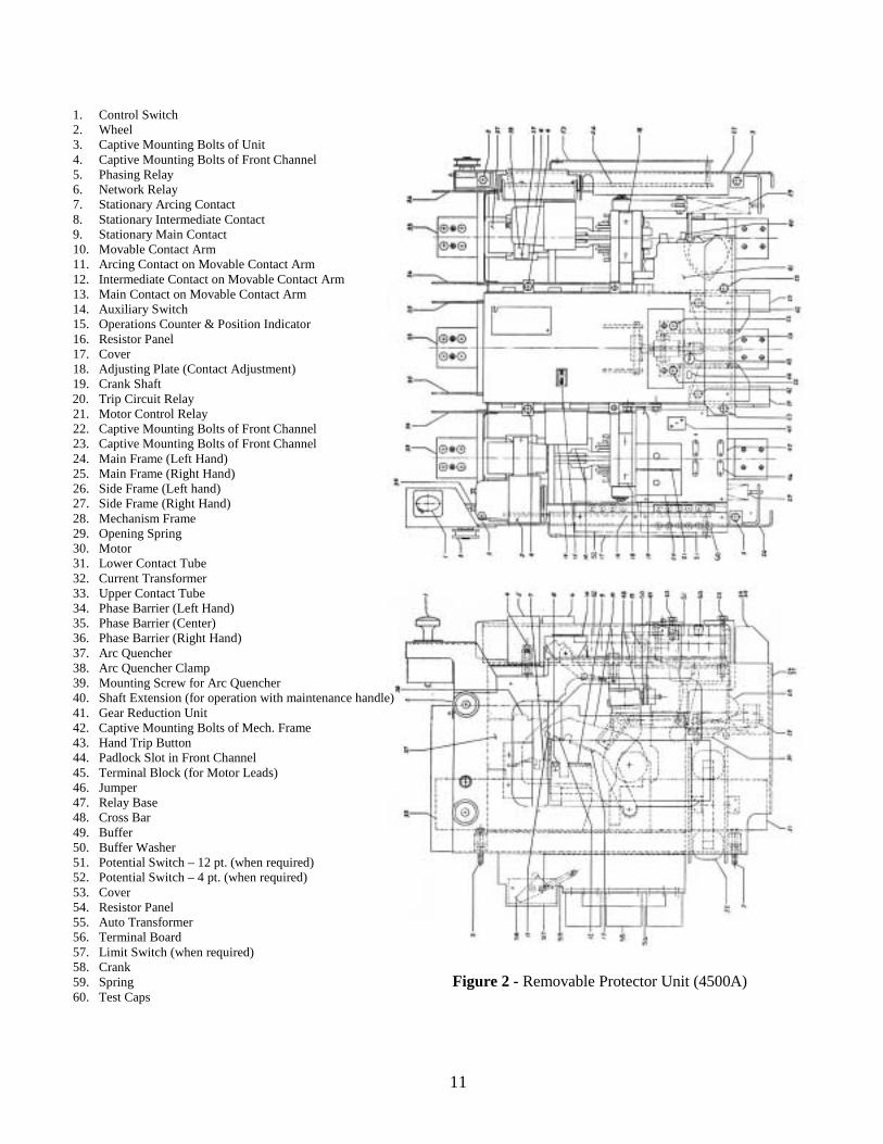
1. Control Switch 2. Wheel 3. Captive Mounting Bolts of Unit 4. Captive Mounting Bolts of Front Channel 5. Phasing Relay 6. Network Relay 7. Stationary Arcing Contact 8. Stationary Intermediate Contact 9. Stationary Main Contact 10. Movable Contact Arm 11. Arcing Contact on Movable Contact Arm 12. Intermediate Contact on Movable Contact Arm 13. Main Contact on Movable Contact Arm 14. Auxiliary Switch 15. Operations Counter & Position Indicator 16. Resistor Panel 17. Cover 18. Adjusting Plate (Contact Adjustment) 19. Crank Shaft 20. Trip Circuit Relay 21. Motor Control Relay 22. Captive Mounting Bolts of Front Channel 23. Captive Mounting Bolts of Front Channel 24. Main Frame (Left Hand) 25. Main Frame (Right Hand) 26. Side Frame (Left hand) 27. Side Frame (Right Hand) 28. Mechanism Frame 29. Opening Spring 30. Motor 31. Lower Contact Tube 32. Current Transformer 33. Upper Contact Tube 34. Phase Barrier (Left Hand) 35. Phase Barrier (Center) 36. Phase Barrier (Right Hand) 37. Arc Quencher 38. Arc Quencher Clamp 39. Mounting Screw for Arc Quencher 40. Shaft Extension (for operation with maintenance handle) 41. Gear Reduction Unit 42. Captive Mounting Bolts of Mech. Frame 43. Hand Trip Button 44. Padlock Slot in Front Channel 45. Terminal Block (for Motor Leads) 46. Jumper 47. Relay Base 48. Cross Bar 49. Buffer 50. Buffer Washer 51. Potential Switch – 12 pt. (when required) 52. Potential Switch – 4 pt. (when required) 53. Cover 54. Resistor Panel 55. Auto Transformer 56. Terminal Board 57. Limit Switch (when required) 58. Crank 59. Spring 60. Test Caps
Figure 2 - Removable Protector Unit (4500A)
12
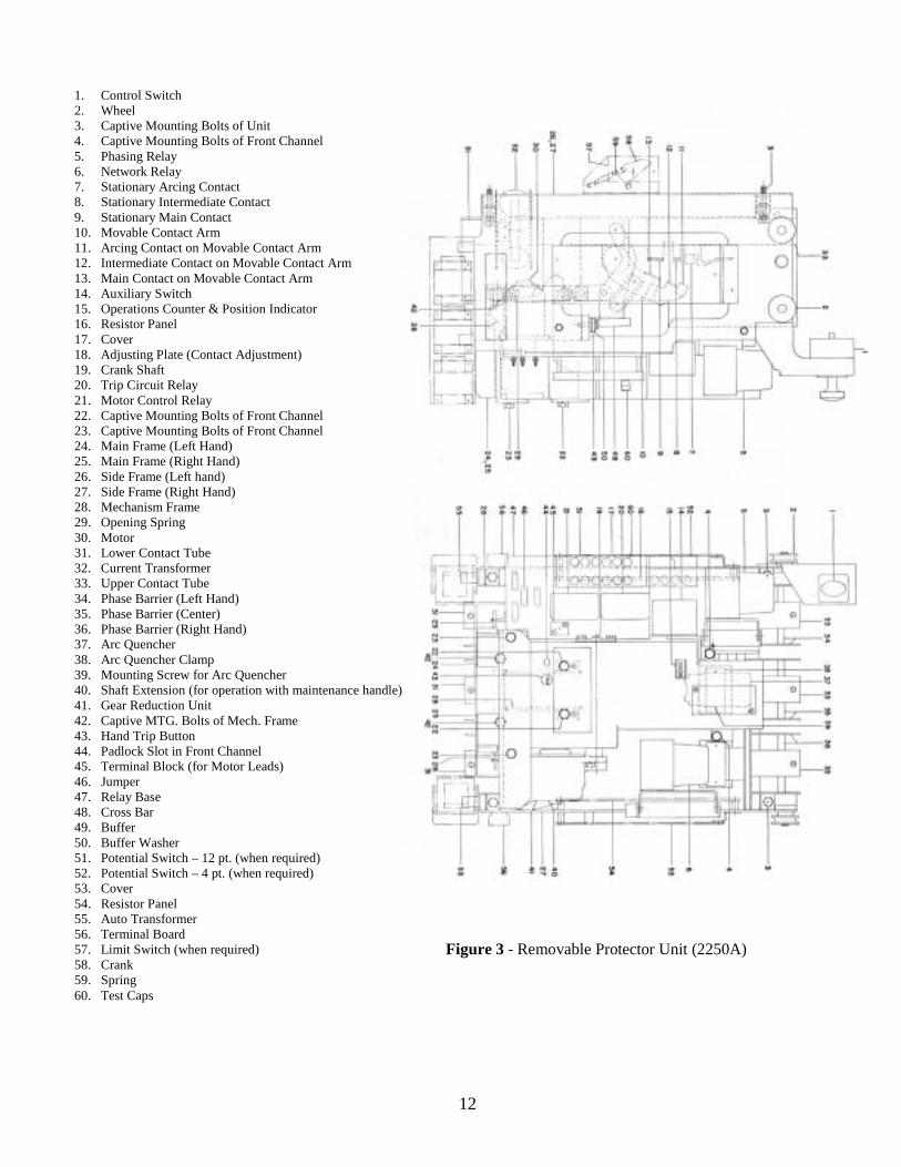
1. Control Switch 2. Wheel 3. Captive Mounting Bolts of Unit 4. Captive Mounting Bolts of Front Channel 5. Phasing Relay 6. Network Relay 7. Stationary Arcing Contact 8. Stationary Intermediate Contact 9. Stationary Main Contact 10. Movable Contact Arm 11. Arcing Contact on Movable Contact Arm 12. Intermediate Contact on Movable Contact Arm 13. Main Contact on Movable Contact Arm 14. Auxiliary Switch 15. Operations Counter & Position Indicator 16. Resistor Panel 17. Cover 18. Adjusting Plate (Contact Adjustment) 19. Crank Shaft 20. Trip Circuit Relay 21. Motor Control Relay 22. Captive Mounting Bolts of Front Channel 23. Captive Mounting Bolts of Front Channel 24. Main Frame (Left Hand) 25. Main Frame (Right Hand) 26. Side Frame (Left hand) 27. Side Frame (Right Hand) 28. Mechanism Frame 29. Opening Spring 30. Motor 31. Lower Contact Tube 32. Current Transformer 33. Upper Contact Tube 34. Phase Barrier (Left Hand) 35. Phase Barrier (Center) 36. Phase Barrier (Right Hand) 37. Arc Quencher 38. Arc Quencher Clamp 39. Mounting Screw for Arc Quencher 40. Shaft Extension (for operation with maintenance handle) 41. Gear Reduction Unit 42. Captive MTG. Bolts of Mech. Frame 43. Hand Trip Button 44. Padlock Slot in Front Channel 45. Terminal Block (for Motor Leads) 46. Jumper 47. Relay Base 48. Cross Bar 49. Buffer 50. Buffer Washer 51. Potential Switch – 12 pt. (when required) 52. Potential Switch – 4 pt. (when required) 53. Cover 54. Resistor Panel 55. Auto Transformer 56. Terminal Board 57. Limit Switch (when required) 58. Crank 59. Spring 60. Test Caps
Figure 3 - Removable Protector Unit (2250A)
13
B. Inner Operating Mechanism (Figure 4 and 6)
After the front channel assembly has been removed the inner operating mechanism may be removed by:
1. Disconnecting closing cam (17) from insulated coupling (22) by removing connecting pin
(23). 2. Disconnecting the wires to the shunt trip coil and permissive switch. 3. Loosen the two captive bolts holding the mechanism to the stationary inner frames. 4. Remove by pulling the inner mechanism frame forward.
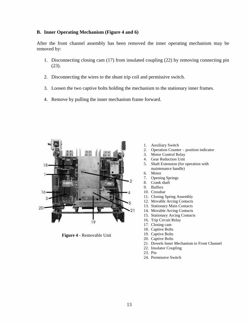
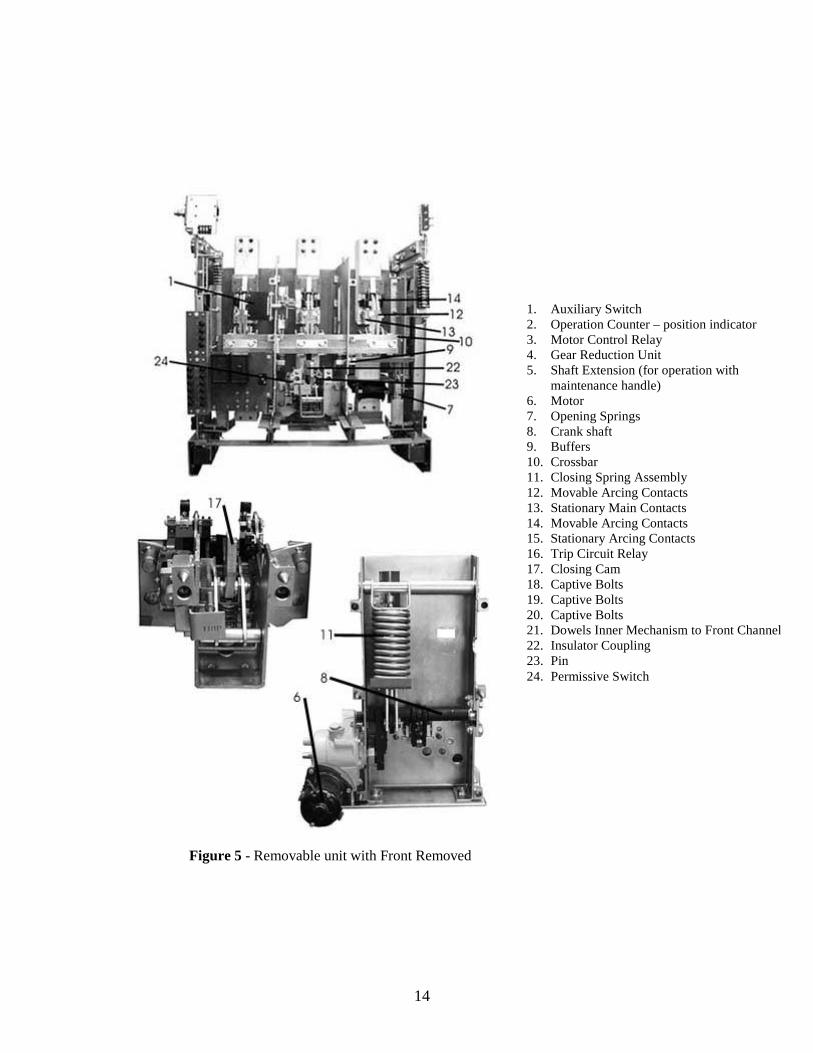
1. Auxiliary Switch 2. Operation Counter – position indicator 3. Motor Control Relay 4. Gear Reduction Unit 5. Shaft Extension (for operation with
maintenance handle) 6. Motor 7. Opening Springs 8. Crank shaft 9. Buffers 10. Crossbar 11. Closing Spring Assembly 12. Movable Arcing Contacts 13. Stationary Main Contacts 14. Movable Arcing Contacts 15. Stationary Arcing Contacts 16. Trip Circuit Relay 17. Closing cam 18. Captive Bolts 19. Captive Bolts 20. Captive Bolts 21. Dowels Inner Mechanism to Front Channel 22. Insulator Coupling 23. Pin 24. Permissive Switch
Figure 4 - Removable Unit
14
Figure 5 - Removable unit with Front Removed
1. Auxiliary Switch 2. Operation Counter – position indicator 3. Motor Control Relay 4. Gear Reduction Unit 5. Shaft Extension (for operation with
maintenance handle) 6. Motor 7. Opening Springs 8. Crank shaft 9. Buffers 10. Crossbar 11. Closing Spring Assembly 12. Movable Arcing Contacts 13. Stationary Main Contacts 14. Movable Arcing Contacts 15. Stationary Arcing Contacts 16. Trip Circuit Relay 17. Closing Cam 18. Captive Bolts 19. Captive Bolts 20. Captive Bolts 21. Dowels Inner Mechanism to Front Channel 22. Insulator Coupling 23. Pin 24. Permissive Switch
15
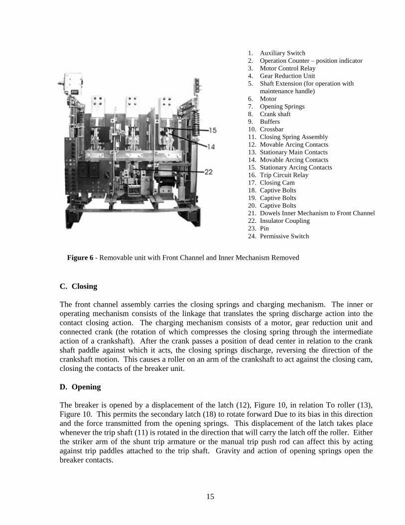
C. Closing
The front channel assembly carries the closing springs and charging mechanism. The inner or operating mechanism consists of the linkage that translates the spring discharge action into the contact closing action. The charging mechanism consists of a motor, gear reduction unit and connected crank (the rotation of which compresses the closing spring through the intermediate action of a crankshaft). After the crank passes a position of dead center in relation to the crank shaft paddle against which it acts, the closing springs discharge, reversing the direction of the crankshaft motion. This causes a roller on an arm of the crankshaft to act against the closing cam, closing the contacts of the breaker unit.
D. Opening
The breaker is opened by a displacement of the latch (12), Figure 10, in relation To roller (13), Figure 10. This permits the secondary latch (18) to rotate forward Due to its bias in this direction and the force transmitted from the opening springs. This displacement of the latch takes place whenever the trip shaft (11) is rotated in the direction that will carry the latch off the roller. Either the striker arm of the shunt trip armature or the manual trip push rod can affect this by acting against trip paddles attached to the trip shaft. Gravity and action of opening springs open the breaker contacts.
Figure 6 - Removable unit with Front Channel and Inner Mechanism Removed
1. Auxiliary Switch 2. Operation Counter – position indicator 3. Motor Control Relay 4. Gear Reduction Unit 5. Shaft Extension (for operation with
maintenance handle) 6. Motor 7. Opening Springs 8. Crank shaft 9. Buffers 10. Crossbar 11. Closing Spring Assembly 12. Movable Arcing Contacts 13. Stationary Main Contacts 14. Movable Arcing Contacts 15. Stationary Arcing Contacts 16. Trip Circuit Relay 17. Closing Cam 18. Captive Bolts 19. Captive Bolts 20. Captive Bolts 21. Dowels Inner Mechanism to Front Channel 22. Insulator Coupling 23. Pin 24. Permissive Switch
16
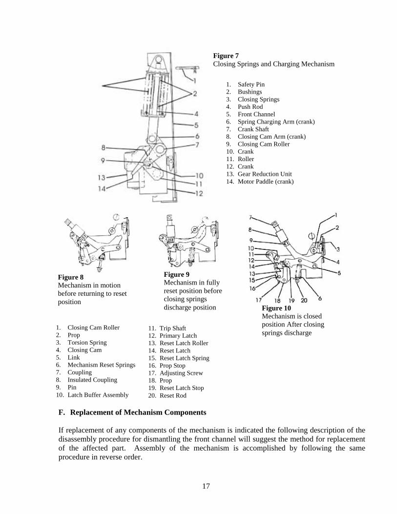
E. Mechanism Adjustments (Figure 8, 9 and 10)
For the mechanism to function properly, it is necessary that the components of the Mechanism linkage reset correctly after an operation cycle. The fully reset position of the linkage occurs just before the closing springs discharge, when the closing cam Roller (1) is in its highest position. During the phase of the cycle immediately preceding, the closing springs are compressed, and the upward movement of the roller (1) away from the closing cam (4) allows the linkage to reset through the action of reset springs (6) and (15). During this phase of the cycle, the closing cam (4) is not engaged by the prop (2) and follows the movement of the roller (1). When in the reset position, the mechanism components should have the following positional relationships.
1. There should exist, between both the primary latch (12) and the secondary latch (14) and their associated rollers, a clearance of from 1/64 to 1/32 inch.
2. The primary latch should have 5/32 (+) 1/32 (-) 0 inch of engagement with roller (13). By
this is meant that it should be necessary to move the latch this distance before tripping occurs. This amount of latch engagement is approximately obtained when an imaginary line through the centers of the trip shaft (11) and roller (13) bisects the engagement surface of the latch (12).
In order to check these adjustments, the front channel must be separated from the back frame for accessibility. Also, the closing cam (4) must be free of engagement with prop (2) and the closing roller (1) must be high enough to be free of contact with the closing cam.
Means of obtaining the required adjustments are:
a. For clearance between the primary latch (12) and its roller (13), adjust screw (17).
b. For clearance between secondary latch (18) and its roller, the adjustment nuts on the end of the reset rod (20) may be advanced or retarded.
3. Latch engagement may be varied by rotating the buffer assembly (10) on its pivot.
Adjustments which may be required on electrical components of the protector, such as the switches, relays and so forth, are discussed in the section of these instructions dealing with the subject of ELECTRICAL DEVICES AND CONTROLS.
17
F. Replacement of Mechanism Components If replacement of any components of the mechanism is indicated the following description of the disassembly procedure for dismantling the front channel will suggest the method for replacement of the affected part. Assembly of the mechanism is accomplished by following the same procedure in reverse order.
1. Closing Cam Roller 2. Prop 3. Torsion Spring 4. Closing Cam 5. Link 6. Mechanism Reset Springs 7. Coupling 8. Insulated Coupling 9. Pin 10. Latch Buffer Assembly
1. Safety Pin 2. Bushings 3. Closing Springs 4. Push Rod 5. Front Channel 6. Spring Charging Arm (crank) 7. Crank Shaft 8. Closing Cam Arm (crank) 9. Closing Cam Roller 10. Crank 11. Roller 12. Crank 13. Gear Reduction Unit 14. Motor Paddle (crank)
Figure 7 Closing Springs and Charging Mechanism
Figure 8 Mechanism in motion before returning to reset position
Figure 10 Mechanism is closed position After closing springs discharge 11. Trip Shaft
12. Primary Latch 13. Reset Latch Roller 14. Reset Latch 15. Reset Latch Spring 16. Prop Stop 17. Adjusting Screw 18. Prop 19. Reset Latch Stop 20. Reset Rod
Figure 9 Mechanism in fully reset position before closing springs discharge position
18
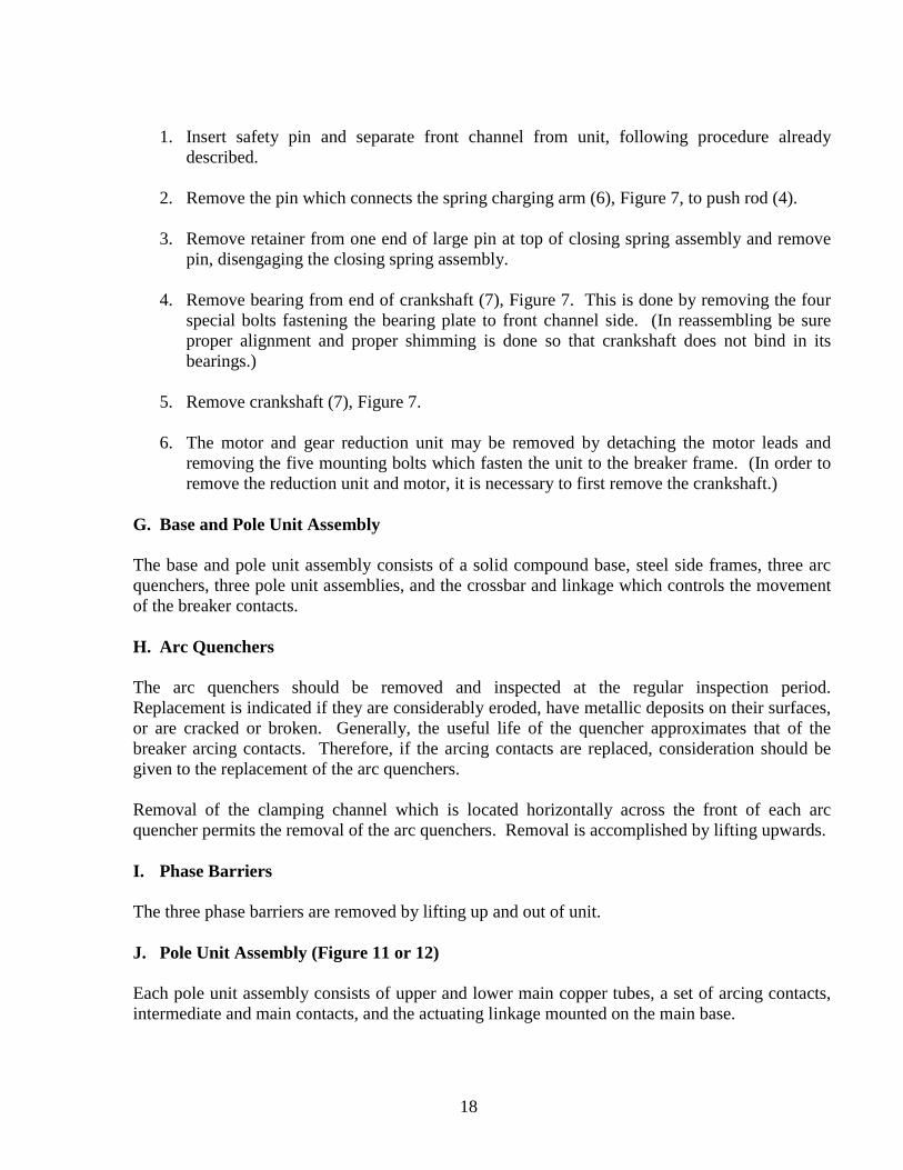
1. Insert safety pin and separate front channel from unit, following procedure already
described.
2. Remove the pin which connects the spring charging arm (6), Figure 7, to push rod (4).
3. Remove retainer from one end of large pin at top of closing spring assembly and remove pin, disengaging the closing spring assembly.
4. Remove bearing from end of crankshaft (7), Figure 7. This is done by removing the four
special bolts fastening the bearing plate to front channel side. (In reassembling be sure proper alignment and proper shimming is done so that crankshaft does not bind in its bearings.)
5. Remove crankshaft (7), Figure 7. 6. The motor and gear reduction unit may be removed by detaching the motor leads and
removing the five mounting bolts which fasten the unit to the breaker frame. (In order to remove the reduction unit and motor, it is necessary to first remove the crankshaft.)
G. Base and Pole Unit Assembly The base and pole unit assembly consists of a solid compound base, steel side frames, three arc quenchers, three pole unit assemblies, and the crossbar and linkage which controls the movement of the breaker contacts. H. Arc Quenchers The arc quenchers should be removed and inspected at the regular inspection period. Replacement is indicated if they are considerably eroded, have metallic deposits on their surfaces, or are cracked or broken. Generally, the useful life of the quencher approximates that of the breaker arcing contacts. Therefore, if the arcing contacts are replaced, consideration should be given to the replacement of the arc quenchers. Removal of the clamping channel which is located horizontally across the front of each arc quencher permits the removal of the arc quenchers. Removal is accomplished by lifting upwards. I. Phase Barriers The three phase barriers are removed by lifting up and out of unit. J. Pole Unit Assembly (Figure 11 or 12)
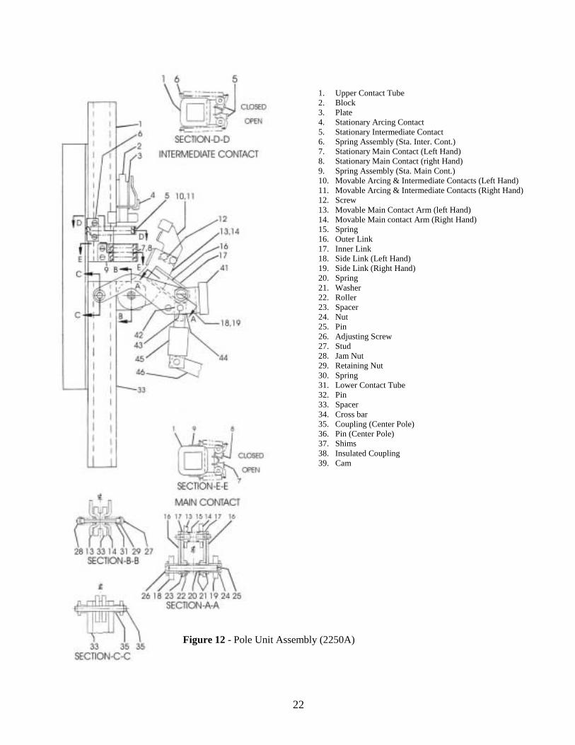
Each pole unit assembly consists of upper and lower main copper tubes, a set of arcing contacts, intermediate and main contacts, and the actuating linkage mounted on the main base.
19
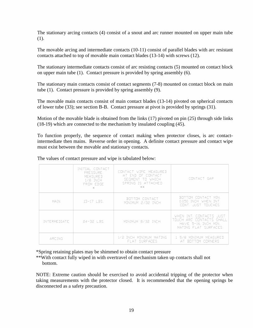
The stationary arcing contacts (4) consist of a snout and arc runner mounted on upper main tube (1). The movable arcing and intermediate contacts (10-11) consist of parallel blades with arc resistant contacts attached to top of movable main contact blades (13-14) with screws (12). The stationary intermediate contacts consist of arc resisting contacts (5) mounted on contact block on upper main tube (1). Contact pressure is provided by spring assembly (6). The stationary main contacts consist of contact segments (7-8) mounted on contact block on main tube (1). Contact pressure is provided by spring assembly (9). The movable main contacts consist of main contact blades (13-14) pivoted on spherical contacts of lower tube (33); see section B-B. Contact pressure at pivot is provided by springs (31). Motion of the movable blade is obtained from the links (17) pivoted on pin (25) through side links (18-19) which are connected to the mechanism by insulated coupling (45). To function properly, the sequence of contact making when protector closes, is arc contact-intermediate then mains. Reverse order in opening. A definite contact pressure and contact wipe must exist between the movable and stationary contacts. The values of contact pressure and wipe is tabulated below:
*Spring retaining plates may be shimmed to obtain contact pressure **With contact fully wiped in with overtravel of mechanism taken up contacts shall not bottom.
NOTE: Extreme caution should be exercised to avoid accidental tripping of the protector when taking measurements with the protector closed. It is recommended that the opening springs be disconnected as a safety precaution.
20
K. Adjustment of Contact Wipe and Alignment (Figure 11 or 12) On a specific pole the difference between the first and last contact making is to be a maximum of 1/32 inch. Between poles the maximum difference is to be 1/16 inch. If the contacts on outside poles lead or lag the contact on the center pole, adjustment should be made by either shimming under main copper tube or by means of adjustment plate on crossbar. The center pole adjustment should be made by means of the coupling (45) to the mechanism. It is best to first make adjustment to the center pole and then to adjust the outer poles if necessary. To adjust by means of the coupling (45). Remove pin connecting coupling (45) and cam (46). Unscrew coupling (45), add shims (44) to increase wipe on contacts; remove shims to decrease. Be sure that coupling, when screwed back in place, is snug when holes in coupling (45) and cam (46) are lined up to replace pin. The moveable main contact blades (13-14) should be in parallel planes vertical to stationary contacts. The space between them is to be approximately 3/8 inch. Spring pressure at the spherical pivots of the 4500 ampere unit where the blades are hinged to lower tubes shall be approximately 150-200 pounds. Maintaining 1-1/8 plus (+) or minus (-) 1/16 inch dimension between washer (30) and spring retainer (32) will provide this pressure. Spring pressure at the spherical pivots of the 2250 ampere units where the blades are hinged to lower tube shall be approximately 150 pounds. Maintain ¾ inch dimension between face of blades and top of washer over springs. The spacer affixed to the RH contact blade (14) to have approximately 1/64 inch clearance between spacer and contact blade (13). (Spacers to be shimmed if necessary.) Caution – Spacer shall not prevent contact arms from closing in and contacting stationary arcing contact. The movable contact blades (13-14) may be adjusted by turning adjusting screws (26). Be sure when adjustment is completed locknuts (24) are tight. The movable arc and intermediate contacts (10-11) are fastened on to the contact blades (13-14) by two bolts (12) in each contact. Adjustment is accomplished by loosening screws (12) and moving arc and intermediate contacts (10-11) to desired position.
21
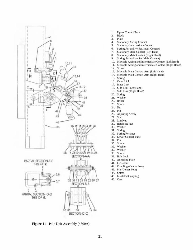
Figure 11 - Pole Unit Assembly (4500A)
1. Upper Contact Tube 2. Block 3. Plate 4. Stationary Arcing Contact 5. Stationary Intermediate Contact 6. Spring Assembly (Sta. Inter. Contact) 7. Stationary Main Contact (Left Hand) 8. Stationary Main Contact (Right Hand) 9. Spring Assembly (Sta. Main Contact) 10. Movable Arcing and Intermediate Contact (Left hand) 11. Movable Arcing and Intermediate Contact (Right Hand) 12. Screw 13. Movable Main Contact Arm (Left Hand) 14. Movable Main Contact Arm (Right Hand) 15. Spring 16. Outer Link 17. Inner Link 18. Side Link (Left Hand) 19. Side Link (Right Hand) 20. Spring 21. Washer 22. Roller 23. Spacer 24. Nut 25. Pin 26. Adjusting Screw 27. Stud 28. Jam Nut 29. Retaining Nut 30. Washer 31. Spring 32. Spring Retainer 33. Lower Contact Tube 34. Pin 35. Spacer 36. Washer 37. Washer 38. Spacer 39. Bolt Lock 40. Adjusting Plate 41. Cross Bar 42. Coupling (Center Pole) 43. Pin (Center Pole) 44. Shims 45. Insulated Coupling 46. Cam
22
1. Upper Contact Tube 2. Block 3. Plate 4. Stationary Arcing Contact 5. Stationary Intermediate Contact 6. Spring Assembly (Sta. Inter. Cont.) 7. Stationary Main Contact (Left Hand) 8. Stationary Main Contact (right Hand) 9. Spring Assembly (Sta. Main Cont.) 10. Movable Arcing & Intermediate Contacts (Left Hand) 11. Movable Arcing & Intermediate Contacts (Right Hand) 12. Screw 13. Movable Main Contact Arm (left Hand) 14. Movable Main contact Arm (Right Hand) 15. Spring 16. Outer Link 17. Inner Link 18. Side Link (Left Hand) 19. Side Link (Right Hand) 20. Spring 21. Washer 22. Roller 23. Spacer 24. Nut 25. Pin 26. Adjusting Screw 27. Stud 28. Jam Nut 29. Retaining Nut 30. Spring 31. Lower Contact Tube 32. Pin 33. Spacer 34. Cross bar 35. Coupling (Center Pole) 36. Pin (Center Pole) 37. Shims 38. Insulated Coupling 39. Cam
Figure 12 - Pole Unit Assembly (2250A)
23
L. Replacing Specific Components (Figure 11 or 12)
1. Stationary arc contact
a. Remove arc quencher.
b. Remove insulated cap. Remove screws, one on each side of cap and lift out.
c. Remove stationary arc contact assembly (4) by removing two screws, one on each side, and lift out.
d. Reassemble new contact in reverse order.
2. Movable Arc and Intermediate Contacts
a. Remove movable arc and intermediate contact (10LH-11RH) by removing two screws
(12) on each contact.
b. Reassemble in reverse order. When reassembling be sure that they are centered and equally spaced on either side of stationary arc contact to within 0.010 to 0.060 inch.
3. Stationary Intermediate Contacts
a. To replace stationary intermediate contact (5) only, press with point of screw Driver near contact stop and pushing to outside; contact will pop out.
b. To replace stationary intermediate contact spring assembly (6) remove screw at base of
assembly. Note number of spacer washers under spring bracket. If contact segments (5) have not been removed they may be picked out.
c. Reassemble in reverse order.
4. Main Contacts
Normally, it should not be necessary during the life of the protector to replace main contacts. If severe operating conditions result in extensive main contact damage, it might be in order to consider return of the unit for overhaul. However an outline of the procedure for replacement of main contact follows.
5. Stationary Main Contacts
a. To replace stationary main contacts (7LH-8RH) only, press with point of screw driver
at point near contact stop and force to outside. Contact will pop out.
b. To replace contact spring assembly (9) remove two screws each side at base of assembly. Note number of washer spacers under spring holding bracket.
24
c. Reassemble in reverse order.
6. Movable Main Contacts (Figure 11 or 12)
Refer to Section A-A
a. Loosen jam nuts (24) and back out adjusting screws (26).
b. Pin (25) can now be pulled out. When pin (25) is being removed, remove spring (20) and wasters (21).
c. Swing links (16 and 17) up and remove from blades (13 and 14). Care should be taken
not to allow roller (22) and spacer (23) to fall out of link (17). If they do replace, after cleaning and lubricating, in position shown (Section A-A).
d. Remove nuts (28 and 29) from stud (27) through blades at spherical pivot. Washers
(30), springs (31), and retainer (32) can now be removed.
e. Hold blades apart and remove spring (15) from between blades.
f. Blades may now be carefully removed care being taken not to nick or damage spherical contact surfaces.
g. Reassemble in reverse order.
7. Current Transformers
The current transformer is located on the lower portion of main copper tube of each pole. The polarity mark (H1) should always face the transformer terminals.
a. Remove the breaker unit from its enclosure.
b. Remove barrier at bottom of CT by removing bracket upon which it rests.
c. Remove wires connected to CT terminals.
d. Remove CT by unbolting from bracket to which it is fastened
e. Reassemble in reverse order. 8. Autotransformers
For protectors rated 277/480 volts there are two banks of autotransformers. Three in each set connected in wye with neutral grounded. One set connected to network studs and one set connected to the transformer studs of the protector. On standard protectors they are located
25
along the bottom of the side frames of the unit. On the special unit for type D-10 open frames they are located on the back side of the main base.
a. To replace, disconnect wires from autotransformer at the adjacent terminal board.
b. Remove hardware holding autotransformer to its supporting bracket and remove
autotransformer.
Replace new one in reverse order.
Figure 13 - Auxiliary Switch and Linkage
VII. ELECTRICAL DEVICES AND CONTROL
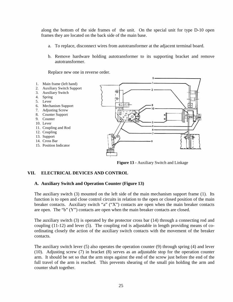
A. Auxiliary Switch and Operation Counter (Figure 13)
The auxiliary switch (3) mounted on the left side of the main mechanism support frame (1). Its function is to open and close control circuits in relation to the open or closed position of the main breaker contacts. Auxiliary switch “a” (“X”) contacts are open when the main breaker contacts are open. The “b” (Y”) contacts are open when the main breaker contacts are closed.
The auxiliary switch (3) is operated by the protector cross bar (14) through a connecting rod and coupling (11-12) and lever (5). The coupling rod is adjustable in length providing means of co-ordinating closely the action of the auxiliary switch contacts with the movement of the breaker contacts.
The auxiliary switch lever (5) also operates the operation counter (9) through spring (4) and lever (10). Adjusting screw (7) in bracket (8) serves as an adjustable stop for the operation counter arm. It should be set so that the arm stops against the end of the screw just before the end of the full travel of the arm is reached. This prevents shearing of the small pin holding the arm and counter shaft together.
1. Main frame (left hand) 2. Auxiliary Switch Support 3. Auxiliary Switch 4. Spring 5. Lever 6. Mechanism Support 7. Adjusting Screw 8. Counter Support 9. Counter 10. Lever 11. Coupling and Rod 12. Coupling 13. Support 14. Cross Bar 15. Position Indicator
26
1. Replacement
a. Disconnect wires to auxiliary switch.
b. Remove the two mounting bolts holding switch to support bracket (2).
c. Disengage switch (3) from lever (5) by withdrawing to left.
d. Replace new switch in reverse order.
2. Adjustment
a. When the switch is mounted, disconnect breaker opening springs and insert safety pin in closing spring shaft.
b. By means of a bell set, or indicating light, and while operating the breaker with the
maintenance handle, determine that the “a” contacts close before breaker contacts touch and the “b” contacts close when breaker contacts open.
c. The assembly of the auxiliary switch to its operating linkage is to be such that the
arrow on the switch shaft points upward to the front of the protector unit when the linkage is in the “breaker open” position. The length of the operating rod between the cross bar and the auxiliary switch crank is to be set so that the “a” (X”) contacts close when the intermediate contacts are 1/8 inch apart. (With the linkage in the breaker open position the crank is at an angle approximately 39 degrees below horizontal.) From open to close position the crank swings through approximately 63 degrees. After adjustments are made the operation of the counter should be checked to make sure that the operating rod has not been shortened to the point where the counter cannot reset.
B. Permissive Switch (24) (Figure 5 and Figure 14) The permissive switch (24), Figure 5, is mounted on the left side of the inner operating mechanism frame. Its contact which is normally closed is in series with the closing circuit. Operation of the protector manual trip opens the switch contacts. A padlock may be inserted in holes at trip button (see Figure 14). With padlock in this position the closing circuit is open and the protector mechanism is trip free.
1. Replacement
a. Disconnect leads from switch terminals.
b. Remove two screws which fasten the switch supporting bracket to the mechanism frame and remove bracket and switch.
c. Separate bracket and switch by removing four screws.
27
d. Fasten new switch to support and replace on mechanism frame, reconnecting leads.
2. Adjustment
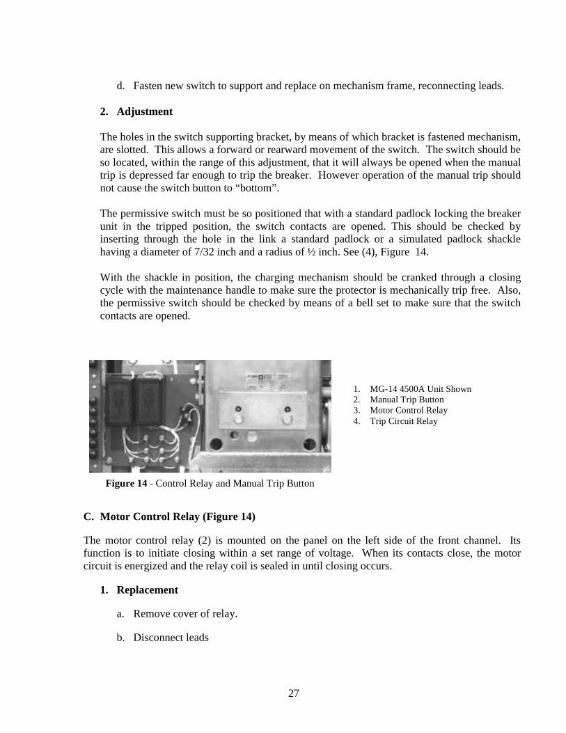
The holes in the switch supporting bracket, by means of which bracket is fastened mechanism, are slotted. This allows a forward or rearward movement of the switch. The switch should be so located, within the range of this adjustment, that it will always be opened when the manual trip is depressed far enough to trip the breaker. However operation of the manual trip should not cause the switch button to “bottom”. The permissive switch must be so positioned that with a standard padlock locking the breaker unit in the tripped position, the switch contacts are opened. This should be checked by inserting through the hole in the link a standard padlock or a simulated padlock shackle having a diameter of 7/32 inch and a radius of ½ inch. See (4), Figure 14. With the shackle in position, the charging mechanism should be cranked through a closing cycle with the maintenance handle to make sure the protector is mechanically trip free. Also, the permissive switch should be checked by means of a bell set to make sure that the switch contacts are opened.
C. Motor Control Relay (Figure 14)
The motor control relay (2) is mounted on the panel on the left side of the front channel. Its function is to initiate closing within a set range of voltage. When its contacts close, the motor circuit is energized and the relay coil is sealed in until closing occurs.
1. Replacement
a. Remove cover of relay.
b. Disconnect leads
1. MG-14 4500A Unit Shown 2. Manual Trip Button 3. Motor Control Relay 4. Trip Circuit Relay
Figure 14 - Control Relay and Manual Trip Button
28
c. Remove two screws which hold base of relay to channel. The heads of these bolts are at back of panel.
2. Adjustment
There is only one adjustment of the motor control relay. This is the setting of the air gap between armature and magnet so that the relay will close its contacts when the voltage applied to the relay coil is correct. The method for testing and adjusting this is described in the section of these instructions titled, ELECTRICAL OPERATION TEST.
D. Trip Circuit Relay (Figure 14)
The trip circuit relay (3) is located on the panel on the left side of the front channel. Its purpose is to increase the trip circuit resistance when the tripping voltage is higher than 90 volts on 125/216V units and 200 volts on 277/480V units.
1. Replacement
Same as for the motor control relay.
2. Adjustment
Like the motor relay, and by the same means, adjustment is made by varying the relay air gap. In this case, the relay should be set to always “pick up” at 90 volts and always “drop out” at 66 volts on 125/216V units and always pick up at 200 volts and always drop out at 147 volts on 277/480V units. This may be checked by applying voltage as described under ELECTRICAL OPERATION TEST with the protector open. The operation of the relay may be checked by observation, or by listening for the audible click which is noticeable when the contacts close. The voltage should first be applied at some low value, and gradually increased until the relay operates. The “drop out” point may be checked in the same way after the relay has “picked up”, by gradually decreasing the voltage.
Normally, it should not be necessary to make an adjustment of either the motor or trip relays, since these are adjusted before shipment from the factory. It is good procedure, however, to check their operation before placement in service.
E. Control Switch (Figure 2)
The control switch (1) is located on the removable protector unit on the top of the left-hand frame.
The control switch provides a means of controlling the operation of the protector at the protector itself.
1. Close
Turn the handle to the “close” position. The motor control relay is energized and sealed in and the protector closes. Upon release of the handle it revolves automatically to the next adjacent position. In this position after the protector is closed the protector will be allowed to

29
trip by action of the network relay but cannot reclose as the circuit to the motor control relay is open.
2. Automatic
With the handle in the “automatic” position the protector is under the control of the network relays.
3. Trip
Turn the handle to the “trip” position. The trip circuit is energized causing the protector to open by action of the shunt trip. While in the trip position the closing circuit is opened preventing reclosure of the protector.
4. Replacement
The control switch is dismounted by the removal of wire connections, the handle, and the three screws which fasten the front plate of the switch to its support. There are no adjustments required. If a switch is defective, it is recommended that it be returned for repair or replacement.
F. Shunt Trip Device (Figure 15)
The shunt trip device is mounted on the left side of the breaker mechanism frame. When the network relay closes it s trip contacts, or when the control switch is turned to the “trip” position, the trip device coil (8) is energized. This induces armature (9) to close against magnet (6). The armature striker (10) acts against the trip shaft paddle (11) which, in turn rotates trip shaft, (12) displacing the trip latch and opening the breaker. When the breaker opens, two auxiliary switch “a” contacts in the trip circuit open, de-energizing the trip coil. This allows return spring (3) to pull the armature back to its normally open position.
1. Replacement of Trip Coil (8)
a. Disconnect trip coil leads from the terminal block in front of the device.
b. Bend locking tabs of plate (5) away from bolt heads.
c. Remove two bolts securing magnet (6) to the device frame.
d. Remove magnet and coil.
e. Straighten the lower bend in clamping strip (7) and remove coil from magnet.
f. The new coil is assembled to the device by reversing this procedure.
30
2. Adjustment
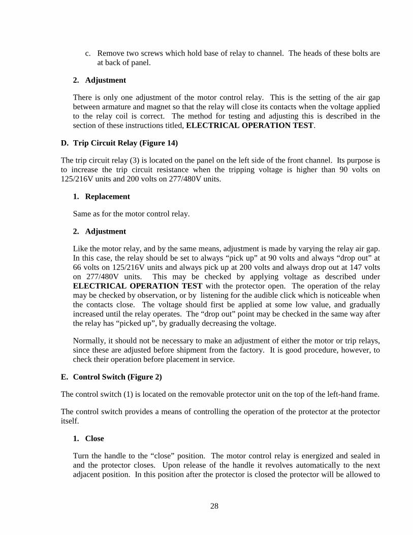
Adjustment of the shunt trip device consists of making certain that the device will trip the breaker when its coil is energized. This is what is meant by “positive trip”. The armature should always produce tripping a measurable distance before it reaches the end of its travel. The recommended minimum over travel is 1/32 inch. A good check of this adjustment consists in placing a 1/32 inch shim between the armature and magnet, then closing the armature to see if the breaker will be tripped. The armature can be closed by pushing upwards on the balance weight (4). Naturally the breaker must be in the closed position. In making this check, care must be taken to avoid personal injury.
The operator must keep clear of the patch of any movable parts while the breaker is closed in case accidental tripping occurs. It would be a good safety precaution to disconnect opening springs.
Adjustment, if necessary, is made by bending the trip shaft paddle (11) to that position in which the required amount of overtravel is obtained. In making the adjustment, overtravel should not be made so great, however, that there is no free movement of the armature before it strikes the trip shaft paddle. Overtravel should not exceed 1/16 inch.
VIII. RENEWAL PARTS
When ordering renewal parts, address the nearest Sales Office of Electronic Technology Incorporated, specifying the quantity required. The parts should be described and the complete nameplate data of the protector should be given. Refer to parts catalog or CD.
Renewal parts which are furnished may not be identical with the original parts since improvements are made from time to time. Parts which are furnished will be interchangeable, however.
1. Mounting Hardware 2. Mounting Bracket 3. Armature Return Spring 4. Armature Balance Weight 5. Locking Plate 6. Magnet 7. Clamp 8. Coil 9. Armature 10. Armature Striker
Figure 15 - Shunt Trip Device
31
32
33
34