Embed Size (px)
Citation preview
eDIN Network Processor Software User Guide
Page 1 of 40
Network Processor Unit (NPU)
Software User Guide
© Mode Lighting (UK) Ltd., 2009
eDIN Network Processor Software User Guide
Page 2 of 40
If you don’t read anything else…
If you don’t generally read manuals then we ask that you just read these 5 golden
rules:
1. In the configuration editor: scenes are defined in columns, inputs are shown in
rows. The intersection between the two is where the input triggers the output.
2. Channels should always be named as follows: <area> : <function>.
The colon : symbol must be included
3. The configuration-editor username is always “configuration”. The
password is whatever you set it to be.
4. An I/O module which has some channels set as an input, and some set as an
output will appear twice: once in the outputs section, and once in the inputs
section.
5. Your NPU must have it’s own unique IP address, and be on the same sub-net
as the computer which you are using to browse its’ web-pages.

eDIN Network Processor Software User Guide
Page 3 of 40
What is the eDIN NPU for? The eDIN Network Processor Unit has many uses:
• A simple method of controlling and setting light levels in any scene using its
inbuilt web-server
• To define the operation of multiple eDIN modules
• To facilitate advanced networking and integration
Hardware Features
The eDIN NPU has the following connections:
2 x M-Bus, on RJ-45 connectors for communicating with other compatible Mode
products, and for powering the eDIN NPU.
1 x Ethernet 10/100 port, via an RJ-45 socket
1 x RS232 port, via terminal blocks
For details on installation and power requirements please refer to the eDIN NPU
Installation Guide which was packed with the NPU module.
NB. If your NPU is the last module on the M-Bus chain then terminate the bus by
plugging an M-Bus Terminator plug into the empty M-Bus RJ-45 socket.
RS232 Port Connection Details
Tx Data out of the NPU
Rx Data into the NPU
RTS (Ready to send) handshaking output from the NPU
CTS (Clear to send) handshaking output from the NPU
0 0v / GNC connection
The Tx connection of the NPU should be wired to the Rx connection of the device
that you want to control. Likewise the Rx connection of the NPU should be wired to
the Tx connection of a device which you want to use to send commands to the NPU
eDIN Network Processor Software User Guide
Page 4 of 40
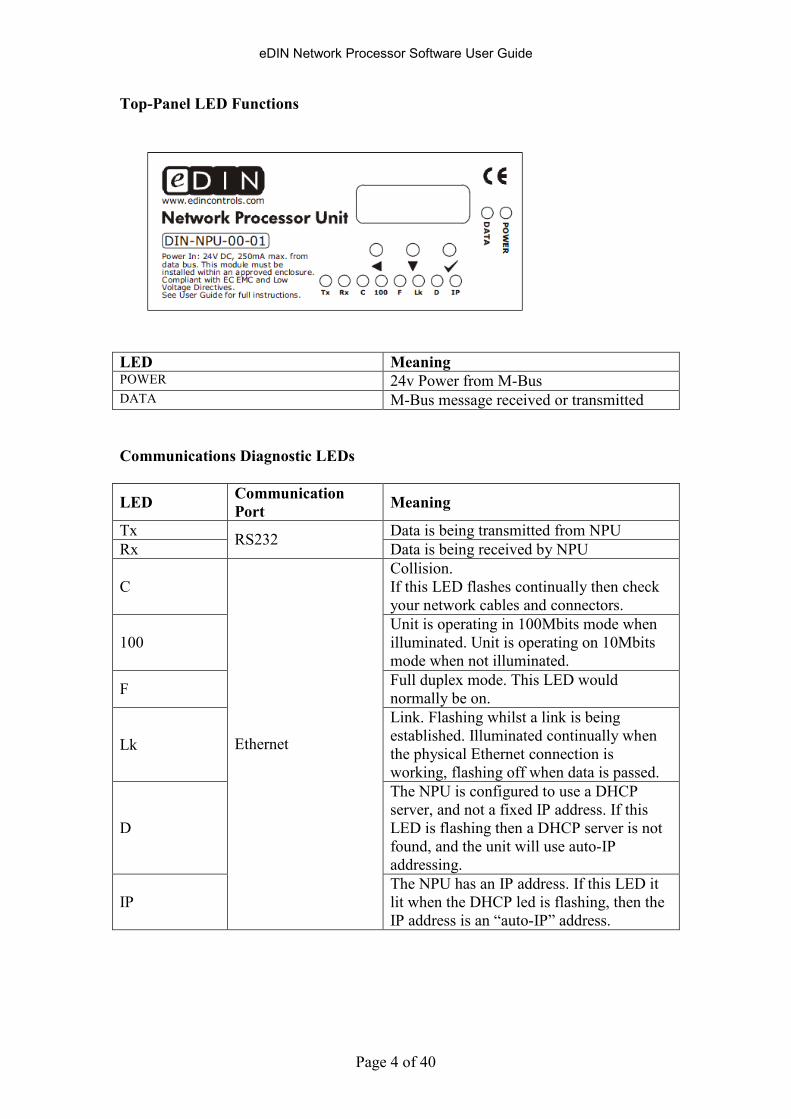
Top-Panel LED Functions
LED Meaning POWER 24v Power from M-Bus DATA M-Bus message received or transmitted
Communications Diagnostic LEDs
LED Communication
Port Meaning
Tx Data is being transmitted from NPU
Rx RS232
Data is being received by NPU
C
Collision.
If this LED flashes continually then check
your network cables and connectors.
100
Unit is operating in 100Mbits mode when
illuminated. Unit is operating on 10Mbits
mode when not illuminated.
F Full duplex mode. This LED would
normally be on.
Lk
Link. Flashing whilst a link is being
established. Illuminated continually when
the physical Ethernet connection is
working, flashing off when data is passed.
D
The NPU is configured to use a DHCP
server, and not a fixed IP address. If this
LED is flashing then a DHCP server is not
found, and the unit will use auto-IP
addressing.
IP
Ethernet
The NPU has an IP address. If this LED it
lit when the DHCP led is flashing, then the
IP address is an “auto-IP” address.
eDIN Network Processor Software User Guide
Page 5 of 40
The Embeded WebServer: Front Page
eDIN is configured using a web browser. No eDIN-specific software or tools are
required.
To access the embedded web server, contained within the eDIN Network Processor
Unit, connect the NPU and your computer to a LAN (Local Area Network).
Each device on a network has its own IP address, which is used to uniquely identifty
it, so that other devices on the network can communicate with it. An IP address is a
number in the format nnn.nnn.nnn.nnn. Usually all devices on the same “subnet” (i.e.
local group of networked devices) will have identical digits for the first three parts of
the IP address. Most networks have a “DHCP Server” which allocates new IP
addresses to new devices on the network. There is usually a DHCP server built into
the network’s router.
Alternatively the IP address can be set manually. This is only recommended for
networks that do not have a DHCP server, as otherwise the DHCP server may allocate
the IP address that has already been manually set for the eDIN module to another
device. That would then mean that there are two devices with the same IP address on
the same network, which will cause problems.
For more information on network organisation please consult your Network Adminstrator or IT team.
Alternatively we recommend the book “TCP/IP Jumpstart” by A. G. Blank, available from Amazon.
The IP address, once allocated, may be checked using the menu options on the 7-
segment LED display of the eDIN NPU. By default the NPU requests an IP address
from your network’s DHCP server. If you do not have a DHCP server, then you’ll
need to set an IP address manually using the menu on the control panel of the NPU. If
you are going to want remote access to your eDIN NPU then you’ll need to use a
fixed IP address.
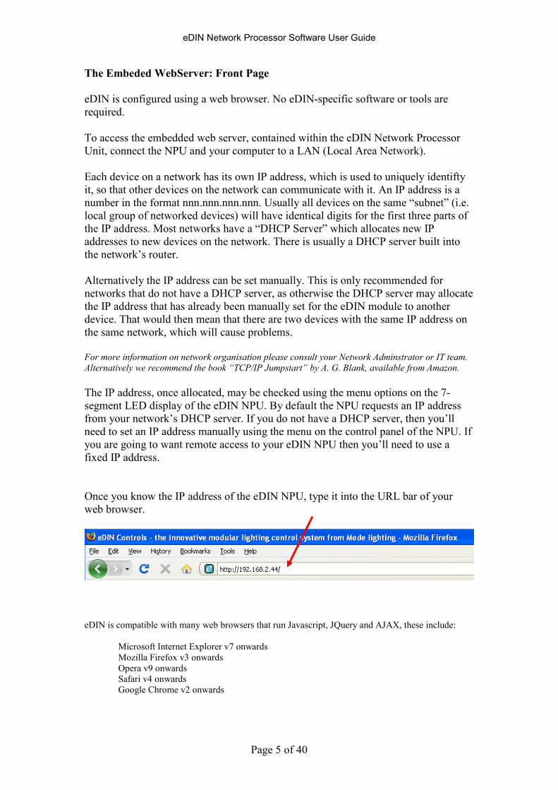
Once you know the IP address of the eDIN NPU, type it into the URL bar of your
web browser.
eDIN is compatible with many web browsers that run Javascript, JQuery and AJAX, these include:
Microsoft Internet Explorer v7 onwards
Mozilla Firefox v3 onwards
Opera v9 onwards
Safari v4 onwards
Google Chrome v2 onwards
eDIN Network Processor Software User Guide
Page 6 of 40
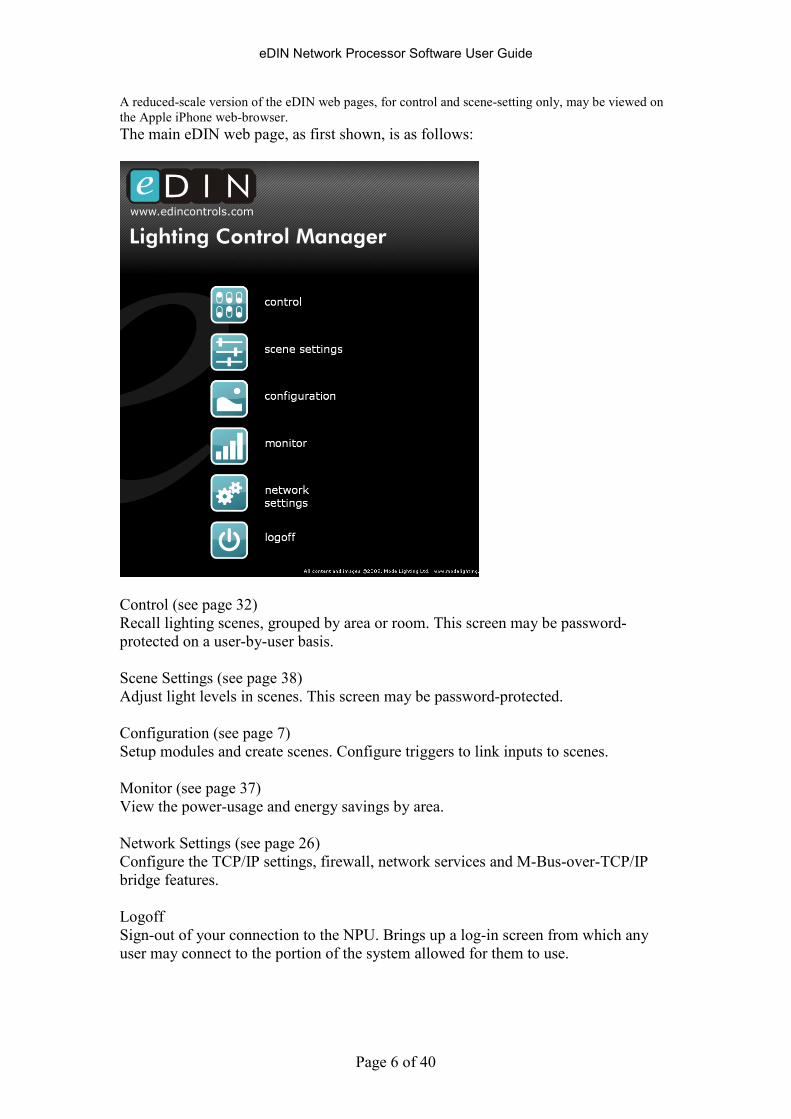
A reduced-scale version of the eDIN web pages, for control and scene-setting only, may be viewed on
the Apple iPhone web-browser.
The main eDIN web page, as first shown, is as follows:
Control (see page 32)
Recall lighting scenes, grouped by area or room. This screen may be password-
protected on a user-by-user basis.
Scene Settings (see page 38)
Adjust light levels in scenes. This screen may be password-protected.
Configuration (see page 7)
Setup modules and create scenes. Configure triggers to link inputs to scenes.
Monitor (see page 37)
View the power-usage and energy savings by area.
Network Settings (see page 26)
Configure the TCP/IP settings, firewall, network services and M-Bus-over-TCP/IP
bridge features.
Logoff
Sign-out of your connection to the NPU. Brings up a log-in screen from which any
user may connect to the portion of the system allowed for them to use.

eDIN Network Processor Software User Guide
Page 7 of 40
Configuring eDIN
The eDIN processor may be configured in the following areas, in the following order:
1. Select modules, and set up hardware
2. Create and edit scenes (output actions)
3. Create and edit triggers (input actions)
4. Create users, and assign access privileges
5. Configure network settings and security

eDIN Network Processor Software User Guide
Page 8 of 40
Setting Up Modules, Scenes and Triggers
The configuration screen is used to setup the hardware modules and what they do.
There is a quick setup feature that can do much of the work for you automatically.
From the front screen select Configuration to access a page which shows a
spreadsheet-type view, with the modules in a column on the left, and scenes in
columns on the right.
Triggers are defined in the intersection between columns (scenes) and rows (inputs) in
the lower section of the window, as shown below:
TRIGGERS
SCENES
OOUUTTPPUUTT
MMOODDUULLEESS
IINNPPUUTT
MMOODDUULLEESS
eDIN Network Processor Software User Guide
Page 9 of 40
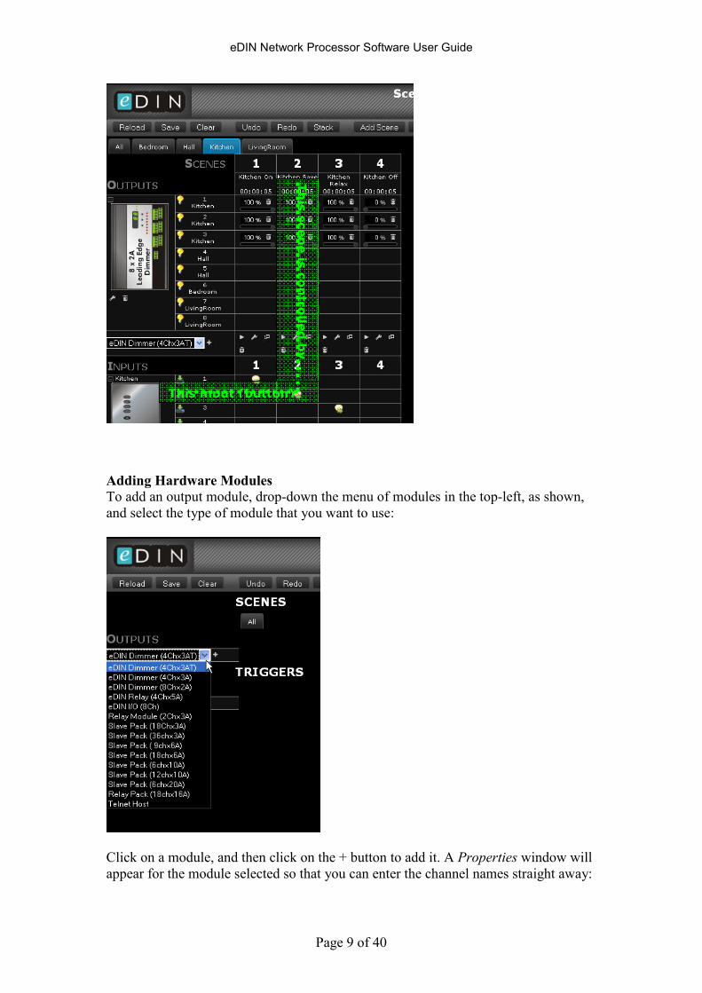
Adding Hardware Modules To add an output module, drop-down the menu of modules in the top-left, as shown,
and select the type of module that you want to use:
Click on a module, and then click on the + button to add it. A Properties window will
appear for the module selected so that you can enter the channel names straight away:
This scene is controlled by
This input (button)
eDIN Network Processor Software User Guide
Page 10 of 40
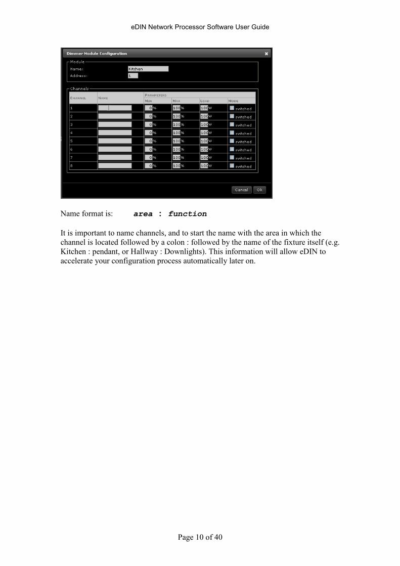
Name format is: area : function
It is important to name channels, and to start the name with the area in which the
channel is located followed by a colon : followed by the name of the fixture itself (e.g.
Kitchen : pendant, or Hallway : Downlights). This information will allow eDIN to
accelerate your configuration process automatically later on.
eDIN Network Processor Software User Guide
Page 11 of 40
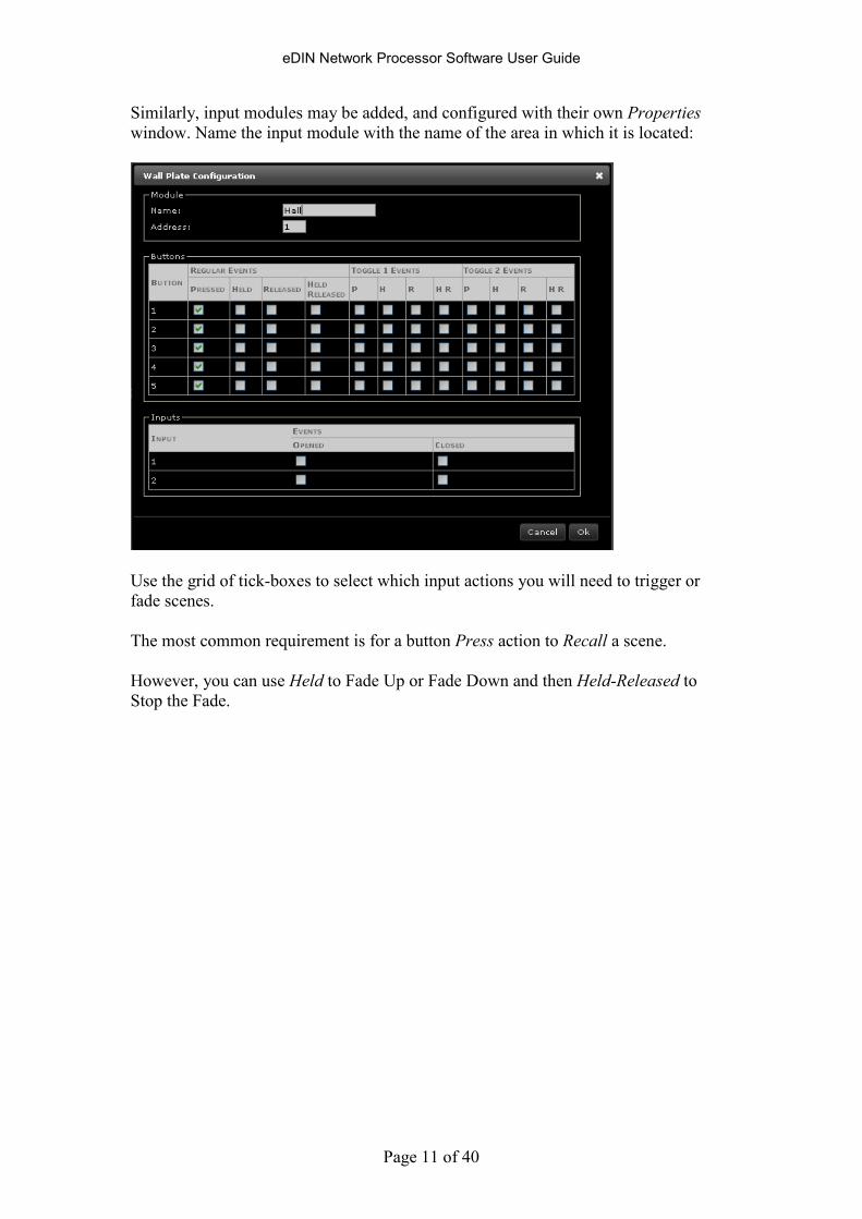
Similarly, input modules may be added, and configured with their own Properties
window. Name the input module with the name of the area in which it is located:
Use the grid of tick-boxes to select which input actions you will need to trigger or
fade scenes.
The most common requirement is for a button Press action to Recall a scene.
However, you can use Held to Fade Up or Fade Down and then Held-Released to
Stop the Fade.
eDIN Network Processor Software User Guide
Page 12 of 40
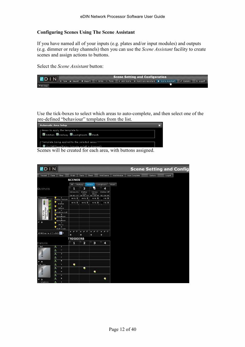
Configuring Scenes Using The Scene Assistant
If you have named all of your inputs (e.g. plates and/or input modules) and outputs
(e.g. dimmer or relay channels) then you can use the Scene Assistant facility to create
scenes and assign actions to buttons.
Select the Scene Assistant button:
Use the tick-boxes to select which areas to auto-complete, and then select one of the
pre-defined “behaviour” templates from the list.
Scenes will be created for each area, with buttons assigned.
eDIN Network Processor Software User Guide
Page 13 of 40
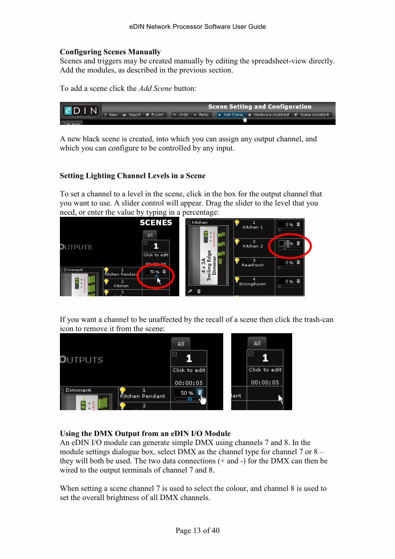
Configuring Scenes Manually Scenes and triggers may be created manually by editing the spreadsheet-view directly.
Add the modules, as described in the previous section.
To add a scene click the Add Scene button:
A new black scene is created, into which you can assign any output channel, and
which you can configure to be controlled by any input.
Setting Lighting Channel Levels in a Scene
To set a channel to a level in the scene, click in the box for the output channel that
you want to use. A slider control will appear. Drag the slider to the level that you
need, or enter the value by typing in a percentage:
If you want a channel to be unaffected by the recall of a scene then click the trash-can
icon to remove it from the scene:
Using the DMX Output from an eDIN I/O Module
An eDIN I/O module can generate simple DMX using channels 7 and 8. In the
module settings dialogue box, select DMX as the channel type for channel 7 or 8 –
they will both be used. The two data connections (+ and -) for the DMX can then be
wired to the output terminals of channel 7 and 8.
When setting a scene channel 7 is used to select the colour, and channel 8 is used to
set the overall brightness of all DMX channels.
eDIN Network Processor Software User Guide
Page 14 of 40
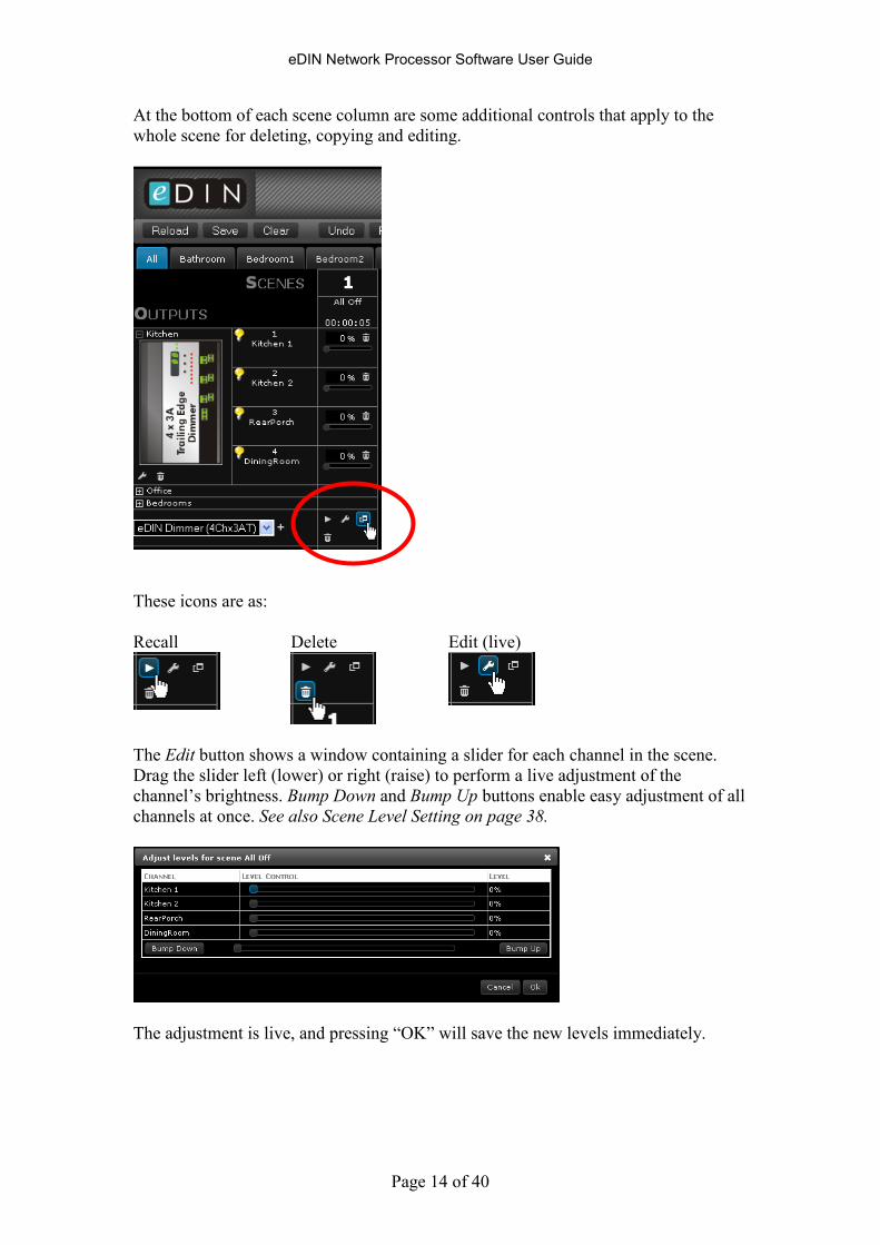
At the bottom of each scene column are some additional controls that apply to the
whole scene for deleting, copying and editing.
These icons are as:
Recall Delete Edit (live)
The Edit button shows a window containing a slider for each channel in the scene.
Drag the slider left (lower) or right (raise) to perform a live adjustment of the
channel’s brightness. Bump Down and Bump Up buttons enable easy adjustment of all
channels at once. See also Scene Level Setting on page 38.
The adjustment is live, and pressing “OK” will save the new levels immediately.
eDIN Network Processor Software User Guide
Page 15 of 40
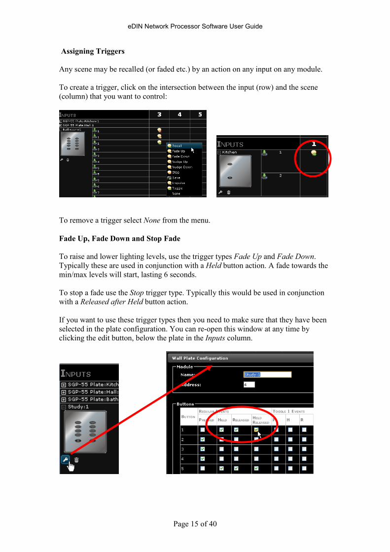
Assigning Triggers
Any scene may be recalled (or faded etc.) by an action on any input on any module.
To create a trigger, click on the intersection between the input (row) and the scene
(column) that you want to control:
To remove a trigger select None from the menu.
Fade Up, Fade Down and Stop Fade
To raise and lower lighting levels, use the trigger types Fade Up and Fade Down.
Typically these are used in conjunction with a Held button action. A fade towards the
min/max levels will start, lasting 6 seconds.
To stop a fade use the Stop trigger type. Typically this would be used in conjunction
with a Released after Held button action.
If you want to use these trigger types then you need to make sure that they have been
selected in the plate configuration. You can re-open this window at any time by
clicking the edit button, below the plate in the Inputs column.
eDIN Network Processor Software User Guide
Page 16 of 40
If you need the same button to have different pressed and held actions then use the
Released trigger instead of the Pressed trigger, otherwise Pressed will trigger just
before Held triggers.
Nudge Up / Nudge Down
A nudge is a fade of 5% over ½ second which stops fading automatically.
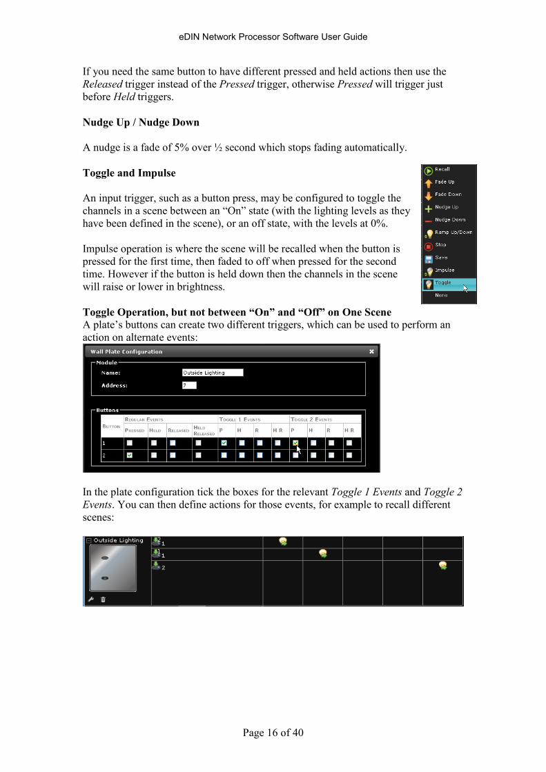
Toggle and Impulse
An input trigger, such as a button press, may be configured to toggle the
channels in a scene between an “On” state (with the lighting levels as they
have been defined in the scene), or an off state, with the levels at 0%.
Impulse operation is where the scene will be recalled when the button is
pressed for the first time, then faded to off when pressed for the second
time. However if the button is held down then the channels in the scene
will raise or lower in brightness.
Toggle Operation, but not between “On” and “Off” on One Scene A plate’s buttons can create two different triggers, which can be used to perform an
action on alternate events:
In the plate configuration tick the boxes for the relevant Toggle 1 Events and Toggle 2
Events. You can then define actions for those events, for example to recall different
scenes:
eDIN Network Processor Software User Guide
Page 17 of 40
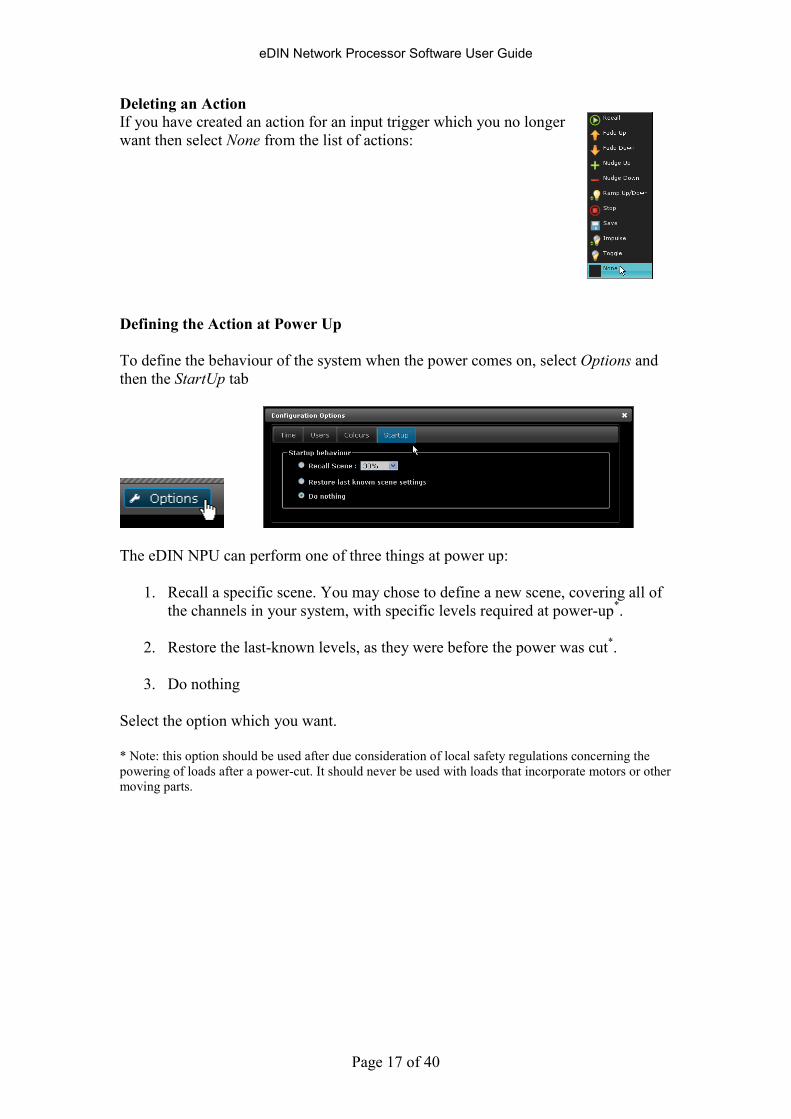
Deleting an Action If you have created an action for an input trigger which you no longer
want then select None from the list of actions:
Defining the Action at Power Up
To define the behaviour of the system when the power comes on, select Options and
then the StartUp tab
The eDIN NPU can perform one of three things at power up:
1. Recall a specific scene. You may chose to define a new scene, covering all of
the channels in your system, with specific levels required at power-up*.
2. Restore the last-known levels, as they were before the power was cut*.
3. Do nothing
Select the option which you want.
* Note: this option should be used after due consideration of local safety regulations concerning the
powering of loads after a power-cut. It should never be used with loads that incorporate motors or other
moving parts.
eDIN Network Processor Software User Guide
Page 18 of 40
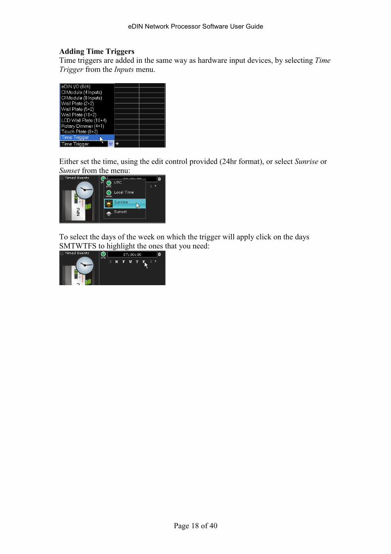
Adding Time Triggers Time triggers are added in the same way as hardware input devices, by selecting Time
Trigger from the Inputs menu.
Either set the time, using the edit control provided (24hr format), or select Sunrise or
Sunset from the menu:
To select the days of the week on which the trigger will apply click on the days
SMTWTFS to highlight the ones that you need:
eDIN Network Processor Software User Guide
Page 19 of 40
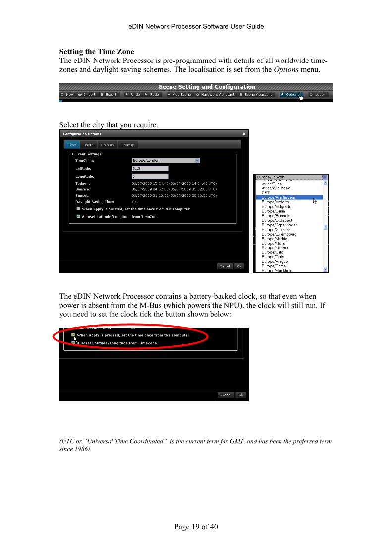
Setting the Time Zone The eDIN Network Processor is pre-programmed with details of all worldwide time-
zones and daylight saving schemes. The localisation is set from the Options menu.
Select the city that you require.
The eDIN Network Processor contains a battery-backed clock, so that even when
power is absent from the M-Bus (which powers the NPU), the clock will still run. If
you need to set the clock tick the button shown below:
(UTC or “Universal Time Coordinated” is the current term for GMT, and has been the preferred term
since 1986)
eDIN Network Processor Software User Guide
Page 20 of 40
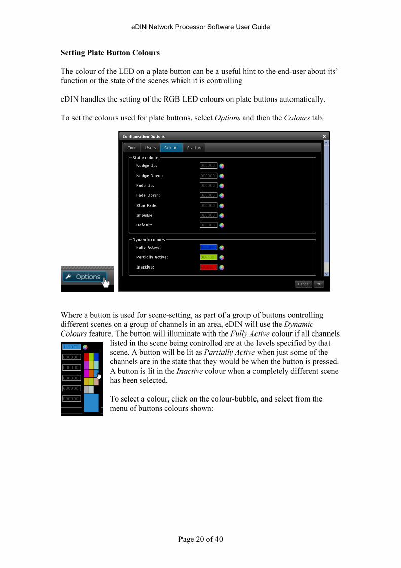
Setting Plate Button Colours
The colour of the LED on a plate button can be a useful hint to the end-user about its’
function or the state of the scenes which it is controlling
eDIN handles the setting of the RGB LED colours on plate buttons automatically.
To set the colours used for plate buttons, select Options and then the Colours tab.
Where a button is used for scene-setting, as part of a group of buttons controlling
different scenes on a group of channels in an area, eDIN will use the Dynamic
Colours feature. The button will illuminate with the Fully Active colour if all channels
listed in the scene being controlled are at the levels specified by that
scene. A button will be lit as Partially Active when just some of the
channels are in the state that they would be when the button is pressed.
A button is lit in the Inactive colour when a completely different scene
has been selected.
To select a colour, click on the colour-bubble, and select from the
menu of buttons colours shown:
eDIN Network Processor Software User Guide
Page 21 of 40
Import and Export
The eDIN NPU stores the configuration in internal flash memory, which is non-
volatile, and which doesn’t require a battery or other power-source to retain the data.
You can export the configuration, to save onto a PC.
You can import a pre-configured system from a file on a PC.
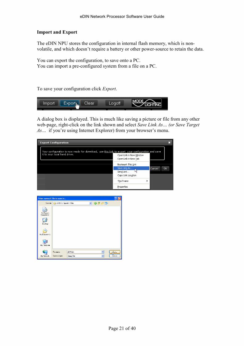
To save your configuration click Export.
A dialog box is displayed. This is much like saving a picture or file from any other
web-page, right-click on the link shown and select Save Link As… (or Save Target
As… if you’re using Internet Explorer) from your browser’s menu.
eDIN Network Processor Software User Guide
Page 22 of 40
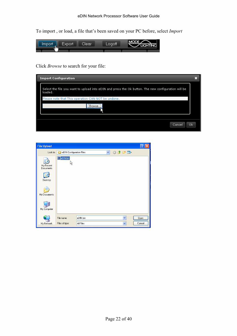
To import , or load, a file that’s been saved on your PC before, select Import
Click Browse to search for your file:
eDIN Network Processor Software User Guide
Page 23 of 40
Setting Up Users
Users may be configured who have different levels of access to control or modify
areas within the eDIN configuration.
For example you may wish to restrict some users to only enable recall of scenes in
certain areas, but not to change their levels. Likewise you may wish to create a user
who is allowed to edit the levels of some scenes, but not others.
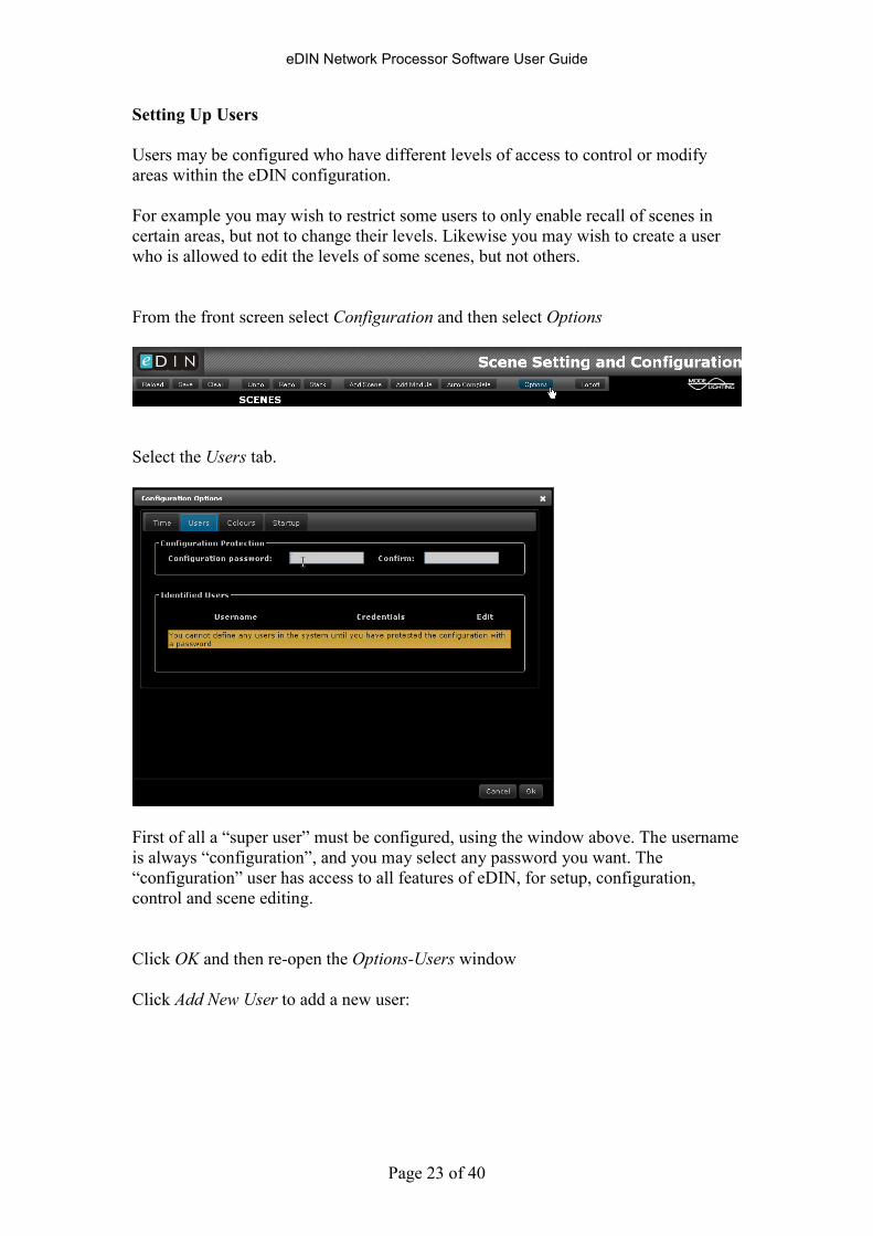
From the front screen select Configuration and then select Options
Select the Users tab.
First of all a “super user” must be configured, using the window above. The username
is always “configuration”, and you may select any password you want. The
“configuration” user has access to all features of eDIN, for setup, configuration,
control and scene editing.
Click OK and then re-open the Options-Users window
Click Add New User to add a new user:

eDIN Network Processor Software User Guide
Page 24 of 40
The new user has their own username and password.
You are allowed to have a username with no password if you want to.
Use the tick boxes provided to decide on the access privileges of the user: whether
they have the ability to edit scene levels, and which areas they can control.

eDIN Network Processor Software User Guide
Page 25 of 40
In the event that a user has forgotten their password then Mode Technical Support can
generate a temporary password, which will work for 24hrs.
eDIN Network Processor Software User Guide
Page 26 of 40
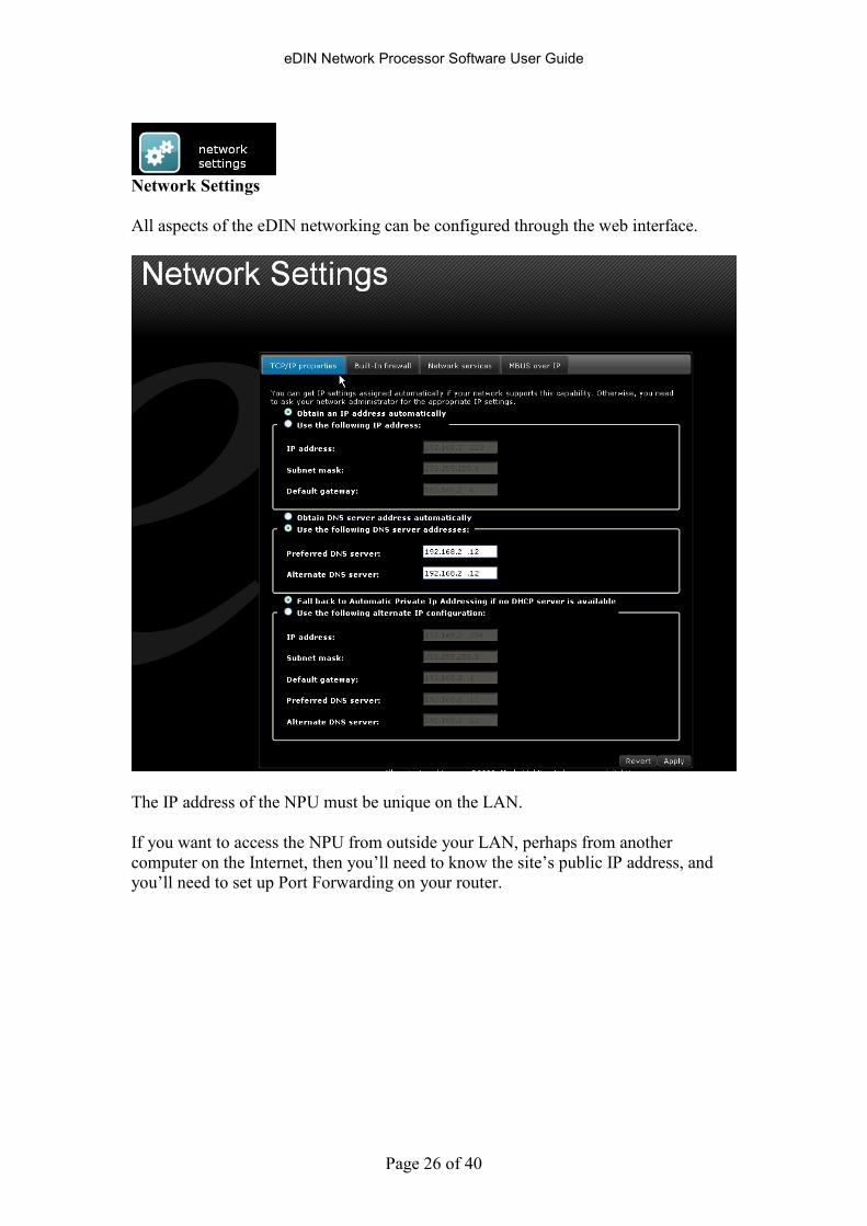
Network Settings
All aspects of the eDIN networking can be configured through the web interface.
The IP address of the NPU must be unique on the LAN.
If you want to access the NPU from outside your LAN, perhaps from another
computer on the Internet, then you’ll need to know the site’s public IP address, and
you’ll need to set up Port Forwarding on your router.
eDIN Network Processor Software User Guide
Page 27 of 40
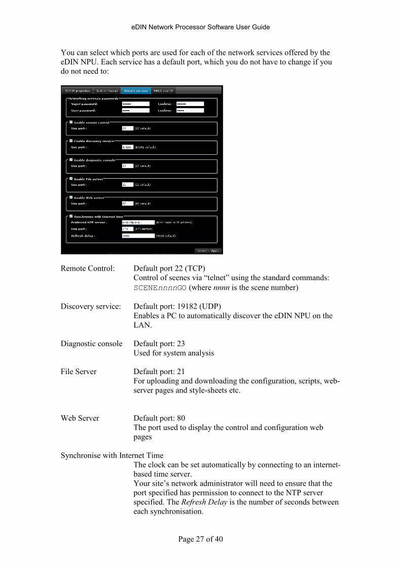
You can select which ports are used for each of the network services offered by the
eDIN NPU. Each service has a default port, which you do not have to change if you
do not need to:
Remote Control: Default port 22 (TCP)
Control of scenes via “telnet” using the standard commands:
SCENEnnnnGO (where nnnn is the scene number)
Discovery service: Default port: 19182 (UDP)
Enables a PC to automatically discover the eDIN NPU on the
LAN.
Diagnostic console Default port: 23
Used for system analysis
File Server Default port: 21
For uploading and downloading the configuration, scripts, web-
server pages and style-sheets etc.
Web Server Default port: 80
The port used to display the control and configuration web
pages
Synchronise with Internet Time
The clock can be set automatically by connecting to an internet-
based time server.
Your site’s network administrator will need to ensure that the
port specified has permission to connect to the NTP server
specified. The Refresh Delay is the number of seconds between
each synchronisation.
eDIN Network Processor Software User Guide
Page 28 of 40
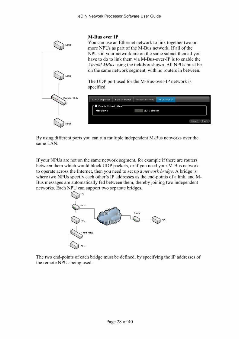
M-Bus over IP You can use an Ethernet network to link together two or
more NPUs as part of the M-Bus network. If all of the
NPUs in your network are on the same subnet then all you
have to do to link them via M-Bus-over-IP is to enable the
Virtual MBus using the tick-box shown. All NPUs must be
on the same network segment, with no routers in between.
The UDP port used for the M-Bus-over-IP network is
specified:
By using different ports you can run multiple independent M-Bus networks over the
same LAN.
If your NPUs are not on the same network segment, for example if there are routers
between them which would block UDP packets, or if you need your M-Bus network
to operate across the Internet, then you need to set up a network bridge. A bridge is
where two NPUs specify each other’s IP addresses as the end-points of a link, and M-
Bus messages are automatically fed between them, thereby joining two independent
networks. Each NPU can support two separate bridges.
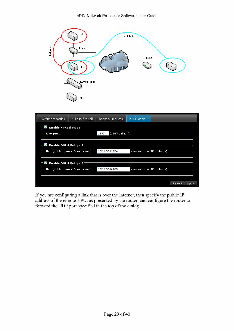
The two end-points of each bridge must be defined, by specifying the IP addresses of
the remote NPUs being used:
NPU
NPU
NPU
Switch / Hub
eDIN Network Processor Software User Guide
Page 29 of 40
If you are configuring a link that is over the Internet, then specify the public IP
address of the remote NPU, as presented by the router, and configure the router to
forward the UDP port specified in the top of the dialog.
eDIN Network Processor Software User Guide
Page 30 of 40
Controlling Networked Devices
The eDIN NPU can send a telnet message to any other network device, as part of a
scene.
Telnet is a standard network protocol which enables two networked devices to
connect and communicate with each other. It is often used to send control commands
from one device to another.
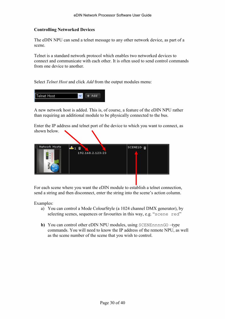
Select Telnet Host and click Add from the output modules menu:
A new network host is added. This is, of course, a feature of the eDIN NPU rather
than requiring an additional module to be physically connected to the bus.
Enter the IP address and telnet port of the device to which you want to connect, as
shown below.
For each scene where you want the eDIN module to establish a telnet connection,
send a string and then disconnect, enter the string into the scene’s action column.
Examples:
a) You can control a Mode ColourStyle (a 1024 channel DMX generator), by
selecting scenes, sequences or favourites in this way, e.g. “scene red”
b) You can control other eDIN NPU modules, using SCENEnnnnGO –type
commands. You will need to know the IP address of the remote NPU, as well
as the scene number of the scene that you wish to control.
eDIN Network Processor Software User Guide
Page 31 of 40
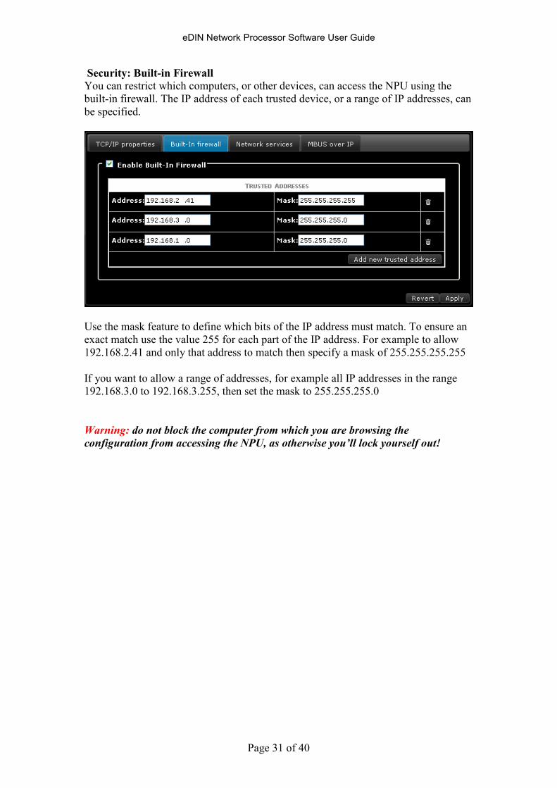
Security: Built-in Firewall You can restrict which computers, or other devices, can access the NPU using the
built-in firewall. The IP address of each trusted device, or a range of IP addresses, can
be specified.
Use the mask feature to define which bits of the IP address must match. To ensure an
exact match use the value 255 for each part of the IP address. For example to allow
192.168.2.41 and only that address to match then specify a mask of 255.255.255.255
If you want to allow a range of addresses, for example all IP addresses in the range
192.168.3.0 to 192.168.3.255, then set the mask to 255.255.255.0
Warning: do not block the computer from which you are browsing the
configuration from accessing the NPU, as otherwise you’ll lock yourself out!
eDIN Network Processor Software User Guide
Page 32 of 40
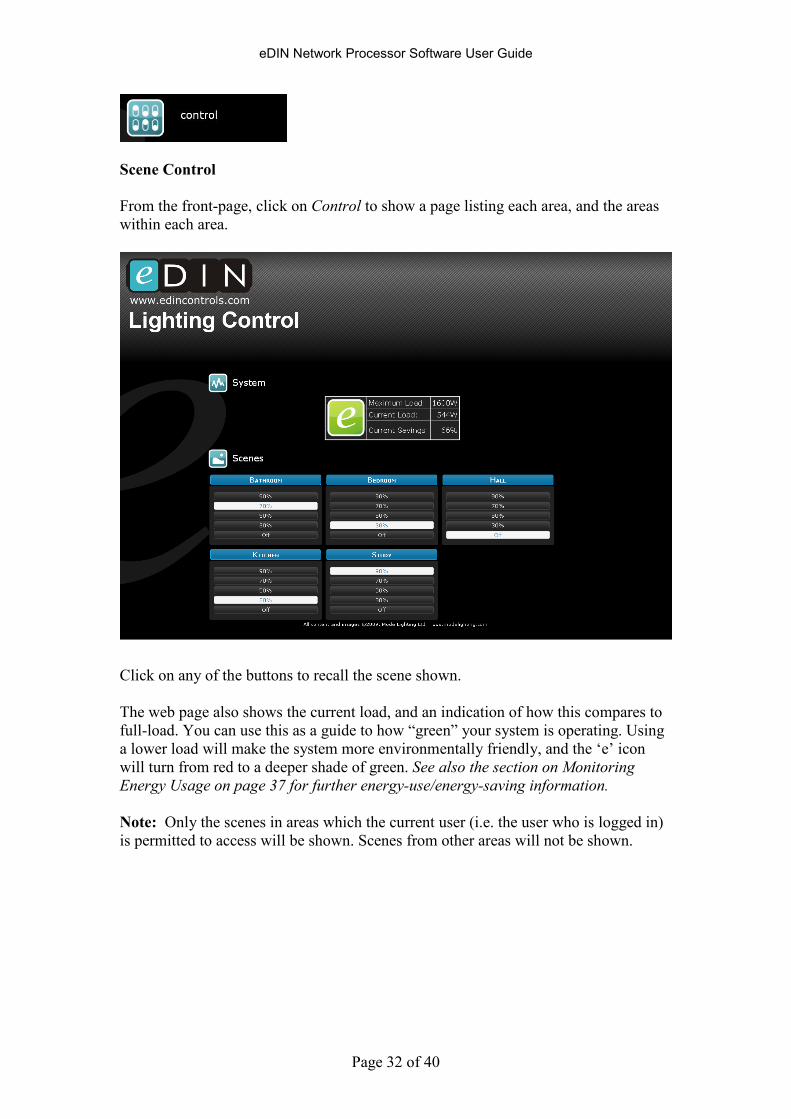
Scene Control
From the front-page, click on Control to show a page listing each area, and the areas
within each area.
Click on any of the buttons to recall the scene shown.
The web page also shows the current load, and an indication of how this compares to
full-load. You can use this as a guide to how “green” your system is operating. Using
a lower load will make the system more environmentally friendly, and the ‘e’ icon
will turn from red to a deeper shade of green. See also the section on Monitoring
Energy Usage on page 37 for further energy-use/energy-saving information.
Note: Only the scenes in areas which the current user (i.e. the user who is logged in)
is permitted to access will be shown. Scenes from other areas will not be shown.
eDIN Network Processor Software User Guide
Page 33 of 40
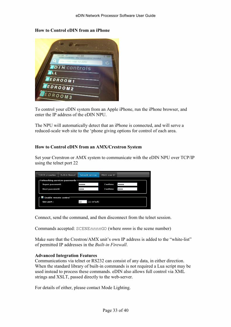
How to Control eDIN from an iPhone
To control your eDIN system from an Apple iPhone, run the iPhone browser, and
enter the IP address of the eDIN NPU.
The NPU will automatically detect that an iPhone is connected, and will serve a
reduced-scale web site to the ‘phone giving options for control of each area.
How to Control eDIN from an AMX/Crestron System
Set your Crerstron or AMX system to communicate with the eDIN NPU over TCP/IP
using the telnet port 22
Connect, send the command, and then disconnect from the telnet session.
Commands accepted: SCENEnnnnGO (where nnnn is the scene number)
Make sure that the Crestron/AMX unit’s own IP address is added to the “white-list”
of permitted IP addresses in the Built-in Firewall.
Advanced Integration Features
Communications via telnet or RS232 can consist of any data, in either direction.
When the standard library of built-in commands is not required a Lua script may be
used instead to process these commands. eDIN also allows full control via XML
strings and XSLT, passed directly to the web-server.
For details of either, please contact Mode Lighting.
eDIN Network Processor Software User Guide
Page 34 of 40
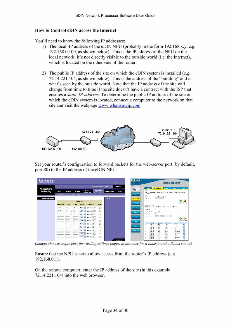
How to Control eDIN across the Internet
You’ll need to know the following IP addresses:
1) The local IP address of the eDIN NPU (probably in the form 192.168.x.y, e.g.
192.168.0.100, as shown below). This is the IP address of the NPU on the
local network; it’s not directly visible to the outside world (i.e. the Internet),
which is located on the other side of the router.
2) The public IP address of the site on which the eDIN system is installed (e.g.
72.14.221.104, as shown below). This is the address of the “building” and is
what’s seen by the outside world. Note that the IP address of the site will
change from time to time if the site doesn’t have a contract with the ISP that
ensures a static IP address. To determine the public IP address of the site on
which the eDIN system is located, connect a computer to the network on that
site and visit the webpage www.whatismyip.com
Set your router’s configuration to forward packets for the web-server port (by default,
port 80) to the IP address of the eDIN NPU.
(images show example port-forwarding settings pages, in this case for a Linksys and a DLink router)
Ensure that the NPU is set to allow access from the router’s IP address (e.g.
192.168.0.1).
On the remote computer, enter the IP address of the site (in this example
72.14.221.104) into the web browser.

eDIN Network Processor Software User Guide
Page 35 of 40
Network Capacity: Notes on Simultaneous TCP Connections
The eDIN NPU supports 8 simultaneous open TCP software connections.
Typically a web-browser connection will use up to four of the simultaneous open
connections to achieve faster page-loading. However the connection times will be
brief, so connections will be freed automatically when they are not in use. Therefore
in practice you can have more than two users using the web-browser at one time.
A device that is remote controlling the eDIN system, for example an AV system
processor (e.g. a Crestron or AMX unit), will use one connection at a time.
Therefore in a typical set-up you can have one web browser and four remote-control
devices simultaneously maintaining open connections to the eDIN NPU.
eDIN Network Processor Software User Guide
Page 36 of 40
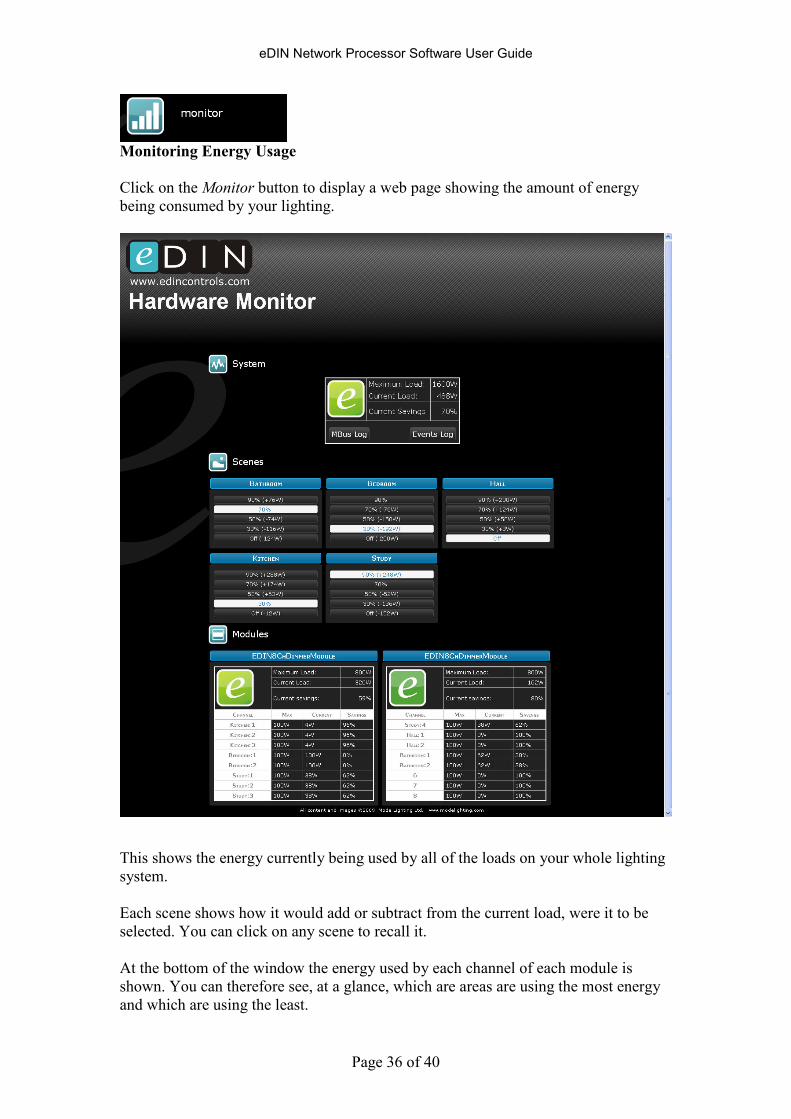
Monitoring Energy Usage
Click on the Monitor button to display a web page showing the amount of energy
being consumed by your lighting.
This shows the energy currently being used by all of the loads on your whole lighting
system.
Each scene shows how it would add or subtract from the current load, were it to be
selected. You can click on any scene to recall it.
At the bottom of the window the energy used by each channel of each module is
shown. You can therefore see, at a glance, which are areas are using the most energy
and which are using the least.
eDIN Network Processor Software User Guide
Page 37 of 40
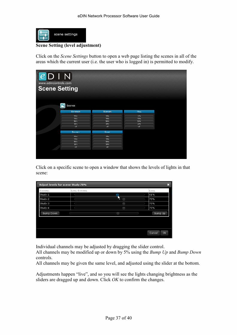
Scene Setting (level adjustment)
Click on the Scene Settings button to open a web page listing the scenes in all of the
areas which the current user (i.e. the user who is logged in) is permitted to modify.
Click on a specific scene to open a window that shows the levels of lights in that
scene:
Individual channels may be adjusted by dragging the slider control.
All channels may be modified up or down by 5% using the Bump Up and Bump Down
controls.
All channels may be given the same level, and adjusted using the slider at the bottom.
Adjustments happen “live”, and so you will see the lights changing brightness as the
sliders are dragged up and down. Click OK to confirm the changes.

eDIN Network Processor Software User Guide
Page 38 of 40
How to Update the Software Inside eDIN
From the front page click on Settings and then select the Software Upgrade tab.
The current version of firmware and the editor software are shown. If you ever need
to contact Mode Technical Support, please make a note of these.
To update either part click on Clich here to access the Firmware Update page.
eDIN contains two sets of software:
1) The firmware, which handles M-Bus communications, memory
management and all of the internal features that make up eDIN.
2) The Configuration Editor, which is the embedded web application, visible
to engineers and users via the web browser.
The firmware has been written and created by Mode Lighting (UK) Ltd and can not
be modified externally. However updates are available from time to time, which
contain new or enhanced features as part of our programme of continual product
development, based on customer feedback.
The Configuration Editor, or web-application, has also been created by Mode
Lighting (UK) Ltd. Using various web-technologies such as CSS and Javascript it is
possible for a suitably skilled developer to modify the look and feel of the web pages,
including the Style-Sheets and all graphics associated with them. For more
information on this, please contact the sales department to discuss OEM options and
Web Customisation.
You can make a backup of the
current firmware/web-
application using the Backup
links, or upgrade the eDIN
NPU, using the Upgrade
options.
Firmware and web-application
image files can be downloaded
from the website:
www.edincontrols.co.uk
A
access............................................................ 23
access privileges ........................................... 24 Add Scene......................................................13

eDIN Network Processor Software User Guide
Page 39 of 40
adjustment................................................... 38
AJAX.............................................................. 5
alternate events ............................................. 16
AMX ............................................................ 33
area ............................................................... 10
areas............................................ 12, 23, 24, 32
B
block ............................................................. 31
brightness ..................................................... 38
Button Colours ............................................. 20
button Press .................................................. 11
buttons .......................................................... 16
C
channel ......................................................... 13
channel names ................................................ 9
channels ........................................................ 38
Chrome ........................................................... 6
city................................................................ 19
clock ....................................................... 19, 27
Collision ......................................................... 4
ColourStyle................................................... 30
configuration ................................................ 21
Configuration ................................................. 8
control........................................................... 23
Control......................................................... 32
copying ......................................................... 14
Crestron....................................................... 33
CSS............................................................... 39
D
daylight saving ............................................. 19
deleting ......................................................... 14
DHCP ......................................................... 4, 5
DMX ...................................................... 13, 30
duplex ............................................................. 4
E
editing........................................................... 14
editor software .............................................. 39
Energy Usage .............................................. 37
Ethernet .......................................................... 4
Export .......................................................... 21
F
Fade Down................................................... 15
Fade Up ....................................................... 15
file................................................................. 21
Firefox ............................................................ 5
Firewall........................................................ 31
firmware ....................................................... 39
flash memory................................................ 21
G
GMT ............................................................. 19
green ............................................................. 32
H
handshaking.................................................... 3
Held...............................................................16
I
image files.....................................................39
import............................................................22
Import ..........................................................21
Impulse.........................................................16
input module .................................................11
inputs.............................................................12
Integration ...................................................33
Internet ..............................................28, 29, 35
Internet Explorer .............................................5
IP address............................ 4, 5, 26, 29, 30, 31
IP addresses...................................................35
iPhone...........................................................33
J
Javascript ..................................................5, 39
JQuery.............................................................5
L
LAN ..........................................................5, 26
LED display ....................................................5
levels .............................................................38
Link.................................................................4
live ................................................................38
load ...............................................................22
local IP address ............................................35
localisation ....................................................19
lock ...............................................................31
lower .......................................................15, 16
Lua script ......................................................33
M
mask..............................................................31
M-Bus .............................................................4
M-Bus over IP .............................................28
modify...........................................................23
Monitoring ...................................................37
N
network .........................................................28
Network........................................................26
network bridge ..............................................28
network host..................................................30
network services............................................27
networking ....................................................26
NTP...............................................................27
Nudge Down ................................................16
Nudge Up .....................................................16
O
Opera...............................................................5
output module .................................................9
P
password ...........................................23, 24, 25
plate configuration ........................................16
port 22.....................................................27, 33
Port Forwarding ............................................26
eDIN Network Processor Software User Guide
Page 40 of 40
port: 19182 ................................................... 27
port: 23 ......................................................... 27
port: 80 ......................................................... 27
ports.............................................................. 27
Power.............................................................. 4
Power Up ..................................................... 17
Pressed ......................................................... 16
public IP address .......................................... 35
R
raise ........................................................ 15, 16
recall ............................................................. 32
Released ....................................................... 16
remote........................................................... 35
Remote Control ............................................ 27
restrict access................................................ 31
RGB LED..................................................... 20
router ...................................................... 26, 35
router ............................................................ 28
RS232 ........................................................... 33
Rx 3
S
Safari .............................................................. 5
save............................................................... 21
scene ....................................................... 32, 37
Scene ............................................................ 32
Scene Assistant............................................ 12
Scene Setting ............................................... 38
Scene Settings ............................................... 38
SCENEnnnnGO...................................... 30, 33
scenes ............................................................. 8
Scenes........................................................... 13
scene-setting ................................................. 20
Security........................................................ 31
slider ................................................. 13, 14, 38
Software Upgrade......................................... 39
spreadsheet ..................................................... 8
StartUp ......................................................... 17
Stop Fade .....................................................15
Style-Sheets ..................................................39
subnet ............................................................28
Sunrise ..........................................................18
Sunset ............................................................18
super user ......................................................23
T
telnet .......................................................30, 33
Time Triggers ..............................................18
time-zones.....................................................19
Toggle...........................................................16
triggers ....................................................13, 16
Triggers.....................................................8, 15
trusted device ................................................31
Tx 3
U
UDP ........................................................27, 29
Update ..........................................................39
username .......................................................24
Users .............................................................23
UTC...............................................................19
V
Virtual MBus.................................................28
W
web browser ....................................................5
web page .........................................................6
web-application.............................................39
web-browser..................................................36
WebServer .....................................................5
white-list .......................................................33
X
XML .............................................................33
XSLT ............................................................33
E&OE. Subject to update without prior notice.
© Mode Lighting (UK) Ltd. 2009