Embed Size (px)
Citation preview
Document No.: M-W2988AE-13.0
Network Master SeriesMT9090A
MainframeMU909011A
Drop Cable Fault Locator ModuleOperation Manual
13th Edition
For safety and warning information, please read this manual before attempting to use the equipment.Keep this manual with the equipment.
ANRITSU CORPORATION
ii MT9090A/MU909011A Network Master User’s Guide
8 October 2007 (First Edition)20 February2015 (13th Edition)Copyright©2007-2015 ANRITSU CORPORATIONAll rights reserved.
This document and the product to which it relates are protected by copyright law from unauthorized reproduction.
Notice to U.S. Government End Users
The Software and Documentation are “Commercial Items,” as that term is defined at 48 C.F.R. 2.101, consisting of “Commercial Computer Software” and “Commercial Computer Software Documentation,” as such terms are used in 48 C.F.R. 12.212 or 48 C.F.R. 227.7202, as applicable. Consistent with 48 C.F.R. 12.212 or 48 C.F.R. 227.7202-1 through 227.7202-4, as applicable, the Commercial Computer Software and Commercial Computer Software Documentation are being licensed to the U.S. Government end users (a) only as Commercial Items and (b) with only those rights as are granted to all other end users pursuant to the terms and conditions herein. Unpublished rights reserved under the copyright laws of the United States.
• The contents of this manual may be changed without prior notice.
• No part of this manual may be reproduced without the prior written permission of the publisher.
MT9090A/MU909011A Network Master User’s Guide iii
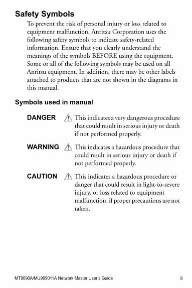
Safety SymbolsTo prevent the risk of personal injury or loss related to equipment malfunction, Anritsu Corporation uses the following safety symbols to indicate safety-related information. Ensure that you clearly understand the meanings of the symbols BEFORE using the equipment. Some or all of the following symbols may be used on all Anritsu equipment. In addition, there may be other labels attached to products that are not shown in the diagrams in this manual.
Symbols used in manual
DANGER This indicates a very dangerous procedure that could result in serious injury or death if not performed properly.
WARNING This indicates a hazardous procedure that could result in serious injury or death if not performed properly.
CAUTION This indicates a hazardous procedure or danger that could result in light-to-severe injury, or loss related to equipment malfunction, if proper precautions are not taken.
iv MT9090A/MU909011A Network Master User’s Guide
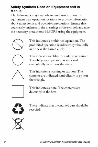
Safety Symbols Used on Equipment and in ManualThe following safety symbols are used inside or on the equipment near operation locations to provide information about safety items and operation precautions. Ensure that you clearly understand the meanings of the symbols and take the necessary precautions BEFORE using the equipment.
This indicates a prohibited operation. The prohibited operation is indicated symbolically in or near the barred circle.
This indicates an obligatory safety precaution. The obligatory operation is indicated symbolically in or near the circle.
This indicates a warning or caution. The contents are indicated symbolically in or near the triangle.
This indicates a note. The contents are described in the box.
These indicate that the marked part should be recycled.
MT9090A/MU909011A Network Master User’s Guide v
For Safety
WARNING !
• ALWAYS refer to the Operation Manual when working near locations at which the alert mark shown on the left is attached. If the advice in the Operation Manual is not followed there is a risk of personal injury or reduced equipment performance. The alert mark shown on the left may also be used with other marks and descriptions to indicate other dangers.
• Overvoltage CategoryThis equipment complies with overvoltage category II defined in IEC 61010. DO NOT connect this equipment to the power supply of overvoltage category III or IV.
vi MT9090A/MU909011A Network Master User’s Guide
• Laser radiation warning• NEVER look directly into
the cable connector on the equipment nor into the end of a cable connected to the equipment. There is a risk of injury if laser radiation enters the eye.
• The Laser Safety label is attached to the equipment for safety use as indicated in “Laser Radiation Markings and Laser Aperture” on page xiv.
Repair • Only qualified service personnel with a knowledge of electrical fire and shock hazards should service this equipment. This equipment cannot be repaired by the operator. DO NOT attempt to remove the equipment covers or unit covers or to disassemble internal components. There are high-voltage parts in this equipment presenting a risk of severe injury or fatal electric shock to untrained personnel. In addition, there is a risk of damage to precision components.
MT9090A/MU909011A Network Master User’s Guide vii
Calibration • he performance-guarantee seal verifies the integrity of the equipment. To ensure the continued integrity of the equipment, only Anritsu service personnel, or service personnel of an Anritsu sales representative, should break this seal to repair or calibrate the equipment. Be careful not to break the seal by opening the equipment or unit covers.If the performance-guarantee seal is broken by you or a third party, the performance of the equipment cannot be guaranteed.
Replacing Battery
• When replacing the battery, use the specified battery and insert it with the correct polarity. If the wrong battery is used, or if the battery is inserted with reversed polarity, there is a risk of explosion causing severe injury or death.
viii MT9090A/MU909011A Network Master User’s Guide
Battery Fluid • DO NOT short the battery terminals and never attempt to disassemble the battery or dispose of it in a fire. If the battery is damaged by any of these actions, the battery fluid may leak. This fluid is poisonous. DO NOT touch the battery fluid, ingest it, or get in your eyes. If it is accidentally ingested, spit it out immediately, rinse your mouth with water and seek medical help. If it enters your eyes accidentally, do not rub your eyes, rinse them with clean running water and seek medical help. If the liquid gets on your skin or clothes, wash it off carefully and thoroughly.
Battery Disposal
• DO NOT expose batteries to heat or fire. Do not expose batteries to fire. This is dangerous and can result in explosions or fire. Heating batteries may cause them to leak or explode.
MT9090A/MU909011A Network Master User’s Guide ix
Laser SafetyClass 1and 3R indicate the danger degree of laser radiation specified below according to IEC 60825-1:2007.
LCD • This instrument uses a Liquid Crystal Display (LCD). DO NOT subject the instrument to excessive force or drop it. If the LCD is subjected to strong mechanical shock, it may break and liquid may leak.This liquid is very caustic and poisonous.
DO NOT touch it, ingest it, or get in your eyes. If it is ingested accidentally, spit it out immediately, rinse your mouth with water and seek medical help. If it enters your eyes accidentally, do not rub your eyes, rinse them with clean running water and seek medical help. If the liquid gets on your skin or clothes, wash it off carefully and thoroughly.
Class 1: Lasers that are safe under reasonably foreseeable conditions of operation, including the use of optical instruments for intrabeam viewing.
x MT9090A/MU909011A Network Master User’s Guide
CAUTION !Use of controls or adjustments or performance of procedures other than those specified herein may result in hazardous radiation exposure.
The use of optical instruments with this product will increase eye hazard.
Class 3R: Lasers that emit in the wavelength range from 302.5 to 106 nm where direct intrabeam viewing is potentially hazardous but the risk is lower than for Class 3B lasers.
MT9090A/MU909011A Network Master User’s Guide xi
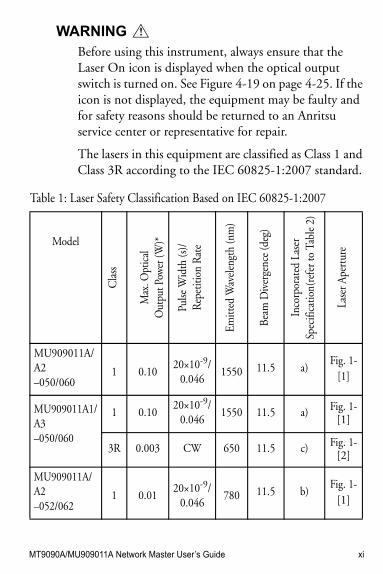
WARNING !
Before using this instrument, always ensure that the Laser On icon is displayed when the optical output switch is turned on. See Figure 4-19 on page 4-25. If the icon is not displayed, the equipment may be faulty and for safety reasons should be returned to an Anritsu service center or representative for repair.
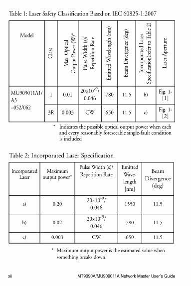
The lasers in this equipment are classified as Class 1 and Class 3R according to the IEC 60825-1:2007 standard.
Table 1: Laser Safety Classification Based on IEC 60825-1:2007
Model
Cla
ss
Max
. Opt
ical
Out
put P
ower
(W)*
Pulse
Wid
th (s
)/R
epet
ition
Rat
e
Emitt
ed W
avel
engt
h (n
m)
Beam
Div
erge
nce
(deg
)
Inco
rpor
ated
Las
er
Spec
ifica
tion(
refe
r to
Tabl
e 2)
Lase
r Ape
rtur
eMU909011A/A2 –050/060
1 0.1020×10⁻⁹/
0.0461550 11.5 a)
Fig. 1-[1]
MU909011A1/A3 –050/060
1 0.1020×10⁻⁹/
0.0461550 11.5 a) Fig. 1-
[1]
3R 0.003 CW 650 11.5 c) Fig. 1-[2]
MU909011A/A2 –052/062
1 0.0120×10⁻⁹/
0.046780 11.5 b)
Fig. 1-[1]
xii MT9090A/MU909011A Network Master User’s Guide
* Maximum output power is the estimated value when something breaks down.
MU909011A1/A3 –052/062
1 0.0120×10⁻⁹/
0.046780 11.5 b) Fig. 1-
[1]
3R 0.003 CW 650 11.5 c) Fig. 1-[2]
* Indicates the possible optical output power when each and every reasonably foreseeable single-fault condition is included
Table 1: Laser Safety Classification Based on IEC 60825-1:2007
Model
Cla
ss
Max
. Opt
ical
Out
put P
ower
(W)*
Pulse
Wid
th (s
)/R
epet
ition
Rat
e
Emitt
ed W
avel
engt
h (n
m)
Beam
Div
erge
nce
(deg
)
Inco
rpor
ated
Las
er
Spec
ifica
tion(
refe
r to
Tabl
e 2)
Lase
r Ape
rtur
eTable 2: Incorporated Laser Specification
Incorporated Laser
Maximum output power*
Pulse Width (s)/Repetition Rate
Emitted Wave-length[nm]
Beam Divergence
(deg)
a) 0.2020×10⁻⁹/
0.0461550 11.5
b) 0.0220×10⁻⁹/
0.046780 11.5
c) 0.003 CW 650 11.5
MT9090A/MU909011A Network Master User’s Guide xiii
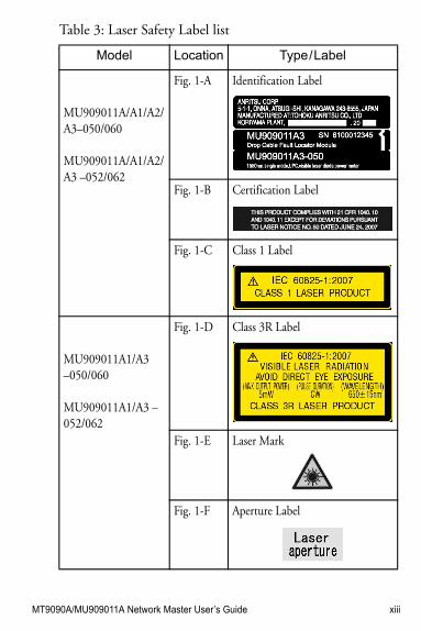
Table 3: Laser Safety Label list
Model Location Type / Label
MU909011A/A1/A2/A3–050/060
MU909011A/A1/A2/A3 –052/062
Fig. 1-A Identification Label
Fig. 1-B Certification Label
Fig. 1-C Class 1 Label
MU909011A1/A3–050/060
MU909011A1/A3 –052/062
Fig. 1-D Class 3R Label
Fig. 1-E Laser Mark
Fig. 1-F Aperture Label
xiv MT9090A/MU909011A Network Master User’s Guide
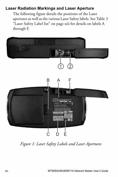
Laser Radiation Markings and Laser ApertureThe following figure details the positions of the Laser apertures as well as the various Laser Safety labels. See Table 3 “Laser Safety Label list” on page xiii for details on labels A through F.
21
B
C
A
D E
F
Figure 1: Laser Safety Labels and Laser Apertures
MT9090A/MU909011A Network Master User’s Guide xv
Electrical Safety To reduce risk of equipment damage, injury, or death, adhere to the following warnings:
• DO NOT use the Network Master or its AC charger/adapter if case for either is cracked or damaged.
• Use the Network Master only with the AC charger/adapter provided for the unit by Anritsu. Anritsu does not guarantee the safety and functionality of other AC charger/adapters.
• DO NOT use the Network Master AC charger/adapter in outdoor or wet environments.
• Ensure that the AC input to the external power supply is within the voltages marked on the power supply case.
• DO NOT attempt to service the product in any way other than routine maintenance as described in this manual.
xvi MT9090A/MU909011A Network Master User’s Guide
For Safety
External Storage MediaThis equipment uses a USB memory as external storage media for storing data and programs.
If this media is mishandled or becomes faulty, important data may be lost. To prevent this chance occurrence, all important data and programs should be backed-up.
Anritsu will not be held responsible for lost data.
Pay careful attention to the following points.
• Never remove the USB memory from the Network Master, while it is being accessed.
• The memory card may be damaged by static electric charges.
Use in a Residential EnvironmentThis instrument is designed for an industrial environment. In a residential environment this instrument may cause radio interference in which case the user may be required to take adequate measures.
Use in Corrosive AtmospheresExposure to corrosive gases such as hydrogen sulfide, sulfurous acid, and hydrogen chloride will cause faults and failures.
Note that some organic solvents release corrosive gases.
MT9090A/MU909011A Network Master User’s Guide xvii
Equipment CertificateAnritsu Corporation certifies that this equipment was tested before shipment using calibrated measuring instruments with direct traceability to public testing organizations recognized by national research laboratories, including the National Institute of Advanced Industrial Science and Technology, and the National Institute of Information and Communications Technology, and was found to meet the published specifications.
Anritsu WarrantyAnritsu Corporation will repair this equipment free-of-charge if a malfunction occurs within one year after shipment due to a manufacturing fault.
However, software fixes will be made in accordance with the separate Software End-User License Agreement. Moreover, Anritsu Corporation will deem this warranty void when:
• The fault is outside the scope of the warranty conditions separately described in the operation manual.
• The fault is due to mishandling, misuse, or unauthorized modification or repair of the equipment by the customer.
• The fault is due to severe usage clearly exceeding normal usage.
• The fault is due to improper or insufficient maintenance by the customer.
xviii MT9090A/MU909011A Network Master User’s Guide
• The fault is due to natural disaster, including fire, wind, flooding, earthquake, lightning strike, or volcanic ash, etc.
• The fault is due to damage caused by acts of destruction, including civil disturbance, riot, or war, etc.
• The fault is due to explosion, accident, or breakdown of any other machinery, facility, or plant, etc.
• The fault is due to use of non-specified peripheral or applied equipment or parts, or consumables, etc.
• The fault is due to use of a non-specified power supply or in a non-specified installation location.
• The fault is due to use in unusual environments(Note).
• The fault is due to activities or ingress of living organisms, such as insects, spiders, fungus, pollen, or seeds.
In addition, this warranty is valid only for the original equipment purchaser. It is not transferable if the equipment is resold.
Anritsu Corporation shall assume no liability for injury or financial loss of the customer due to the use of or a failure to be able to use this equipment.

MT9090A/MU909011A Network Master User’s Guide xix
NoteNoteFor the purpose of this Warranty, "unusual environments" means use:
• In places of direct sunlight• In dusty places• Outdoors• In liquids, such as water, oil, or organic solvents, and
medical fluids, or places where these liquids may adhere
• In salty air or in places where chemically active gases (sulfur dioxide, hydrogen sulfide, chlorine, ammonia, nitrogen oxide, or hydrogen chloride etc.) are present
• In places where high-intensity static electric charges or electromagnetic fields are present
• In places where abnormal power voltages (high or low) or instantaneous power failures occur
• In places where condensation occurs• In the presence of lubricating oil mists• In places at an altitude of more than 2,000 m• In the presence of frequent vibration or mechanical
shock, such as in cars, ships, or airplanes
Anritsu Corporation ContactIn the event that this equipment malfunctions, contact an Anritsu Service and Sales office. Contact information can be found on the last page of the printed version of this manual, and is available in a separate file on the CD version.
xx MT9090A/MU909011A Network Master User’s Guide
Notes On Export ManagementThis product and its manuals may require an Export License/Approval by the Government of the product's country of origin for re-export from your country.
Before re-exporting the product or manuals, please contact us to confirm whether they are export-controlled items or not.
When you dispose of export-controlled items, the products/manuals need to be broken/shredded so as not to be unlawfully used for military purpose.
Disposal ProcedureThe product that you have purchased contains a rechargeable battery. The battery is recyclable. At the end of its useful life, under various state and local laws, it may be illegal to dispose of this battery into the municipal waste stream. Check with your local solid waste officials for details in your area for recycling options or proper disposal.
Crossed-out Wheeled Bin SymbolEquipment marked with the Crossed-out Wheeled Bin Symbol complies with council directive 2012/19/EC (the “WEEE Directive”) in European Union.
For Products placed on the EU market after August 13, 2005, please contact your local Anritsu representative at the end of the product's useful life to arrange disposal in accordance with your initial contract and the local law.
MT9090A/MU909011A Network Master User’s Guide xxi
CE Conformity MarkingAnritsu affixes the CE conformity marking on the following product(s) in accordance with the Council Directive 93/68/EEC to indicate that they conform to the EMC and LVD directive of the European Union (EU).
CE marking
1. Product Model
Model: MT9090A MainframeMU909011A Drop Cable Fault Locator Module
2. Applied Directive
EMC: Directive 2004/108/EC
LVD: Directive 2006/95/EC
3 Applied Standards
• EMC Emission:
EN 61326-1: 2013 (Class A)
Immunity:
EN 61326-1: 2013 (Table 2)
xxii MT9090A/MU909011A Network Master User’s Guide
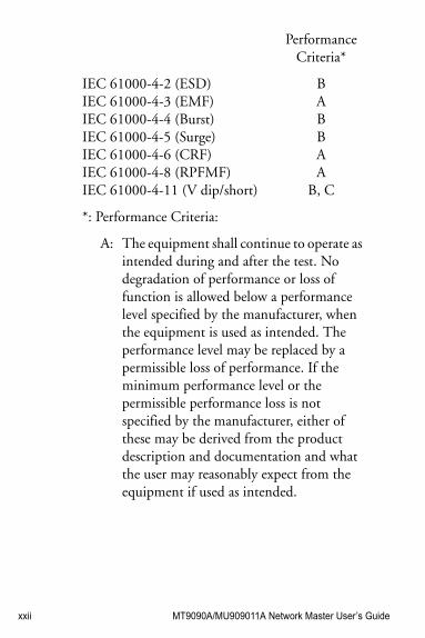
Performance Criteria*
IEC 61000-4-2 (ESD)IEC 61000-4-3 (EMF)IEC 61000-4-4 (Burst)IEC 61000-4-5 (Surge)IEC 61000-4-6 (CRF)IEC 61000-4-8 (RPFMF)IEC 61000-4-11 (V dip/short)
BABBAA
B, C
*: Performance Criteria:
A: The equipment shall continue to operate as intended during and after the test. No degradation of performance or loss of function is allowed below a performance level specified by the manufacturer, when the equipment is used as intended. The performance level may be replaced by a permissible loss of performance. If the minimum performance level or the permissible performance loss is not specified by the manufacturer, either of these may be derived from the product description and documentation and what the user may reasonably expect from the equipment if used as intended.
MT9090A/MU909011A Network Master User’s Guide xxiii
B:. The equipment shall continue to operate as intended after the test. No degradation of performance or loss of function is allowed below a performance level specified by the manufacturer, when the equipment is used as intended. The performance level may be replaced by a permissible loss of performance. During the test, degradation of performance is however allowed. No change of actual operating state or stored data is allowed. If the minimum performance level or the permissible performance loss is not specified by the manufacturer, either of these may be derived from the product description and documentation and what the user may reasonably expect from the equipment if used as intended.
C:. Temporary loss of function is allowed, provided the function is self-recoverable or can be restored by the operation of the controls.
Harmonic current emissions:
EN 61000-3-2: 2006 +A1:2009 A2:2009 (Class A equipment): No limits apply for this equipment with an active input power under 75 W.
• LVD: EN 61010-1: 2010 (Pollution Degree 2)
xxiv MT9090A/MU909011A Network Master User’s Guide
4 Authorized representative
Name:Address, city:Country
Murray ColemanHead of Customer Service EMEAANRITSU EMEA Ltd.200 Capability Green, LutonBedfordshire, LU1 3LUUnited Kingdom
MT9090A/MU909011A Network Master User’s Guide xxv
C-Tick Conformity MarkingAnritsu affixes the C-Tick mark on the following product(s) in accordance with the regulation to indicate that they conform to the EMC framework of Australia/New Zealand.
C-Tick marking
1. Product Model
Models: MT9090A MainframeMU909011A Drop Cable Fault Locator Module
2. Applied Standards
EMC: Emission:
EN 61326-1: 2013(Class A equipment)
xxvi MT9090A/MU909011A Network Master User’s Guide
Technical Support, Services, and RepairsOur Technical Support Center is at your service to answer technical questions and provide return authorization for service, repairs, or other returns.
Technical Support CenterPhone: 1-800-ANRITSU or 972-761-4600 (Canada, U.S., Latin and South America)Fax: +1 972-671-1877e-mail: [email protected]: www.anritsu.com
All returns require a Return Materials Authorization (RMA) number. If possible, return the unit in its original shipping materials. If the original shipping materials are not available, please contact the Technical Support Center for instructions.
Whether or not the warranty period of your Anritsu product has expired, the unit can be returned to Anritsu for repairs. Out-of-warranty repairs are billed for time and materials. Call our Technical Support Center for further information.
Anritsu offers a performance verification service that extensively tests this product and documents its performance. All test equipment used in the verification process is traceable to NIST or NPL standards, and is calibrated annually. Anritsu recommends that you have your unit calibrated annually at our factory.
MT9090A/MU909011A Network Master User’s Guide xxvii
Safety Symbols iiiFor Safety vFor Safety xviEquipment Certificate xviiCE Conformity Marking xxiC-Tick Conformity Marking xxivTechnical Support, Services, and Repairs xxvGeneral Setups4-71-xxviiDisplay From4-311-xxviii
Chapter 1: Quick Start1-1Introduction1-1Basic Configuration1-2Powering Up the Unit1-2
Start Up Sequence1-2Fault Locate Application1-3VFL Testing1-5VIP - Video Inspection Probe (Option)1-6
Chapter 2: Overview2-1Front Panel2-1
LCD Display2-2Softkeys2-3Start Key2-3Arrow Keys and Set Key2-3Menu/Power Key2-5
Back Panel2-5Power and Batteries2-6Installing the Ni-MH battery pack2-7Battery Replacement – Ni-MH pack to AA
xxviii MT9090A/MU909011A Network Master User’s Guide
Ni-MH2-9Bottom Panel2-10Top Connector Panel2-10
AC Charger/Adapter2-12Battery Status LED2-15VFL Port2-17Measurement Port2-17Connecting Peripheral Devices2-21
Changing the Test Module2-24Basic Notes on Use2-26
Chapter 3: General Operation andSystem Setups3-1
General Operation3-1Power Up/Power Down3-1
General Functions Pop-up Menu3-4VFL (Visual Fault Locator)3-6VIP (Video Inspection Probe)3-8Setup3-8Set to Defaults3-14Load3-16Help Function3-17About Function3-17Mass Storage3-18Print Screen3-27Top Menu3-27
Chapter 4: Fault Locate Application4-1Overview4-1Starting the Fault Locate Application4-1Fault Locate Application Setups4-4
MT9090A/MU909011A Network Master User’s Guide xxix
Fault Locate Preferences Setups4-4General Setups4-7Fault Locate Parameters Setups4-7Auto Save Setups4-9
Power Meter Step Screen4-13Setting the Power Meter Threshold Value
4-16Fault Locate Step Screen4-17
Fiber Route – Schematic View4-18Test Information Area4-19Total Loss Threshold Indicator4-20Event Table4-20Event Description Dialog4-24Laser On Icon4-25
Trace View Screen4-26A to B Cursor Distance4-262-Point Loss (dB) Measurement4-26Trace Graph4-27Softkeys4-29Display From4-31Selecting and Positioning Cursors4-31Zoom In/Zoom Out4-32
Fault Locate Test4-34Real Time Testing4-37Connection Check4-38Working with Fault Locate Trace Files4-40
Loading Trace Files4-40Saving Trace Files4-40
Chapter 5: Video Inspection Probe (VIP) Option5-1
xxx MT9090A/MU909011A Network Master User’s Guide
Video Inspection Probe (VIP)5-2Probe Tips5-2
VIP Setup5-3Accessing VIP Mode5-8
Exiting VIP Mode5-10Working with VIP Image Files5-10
Saving VIP Images5-10Loading a VIP Image5-12Mass Storage File Operations5-14
Chapter 6: Updating Firmware6-1Updating the Firmware6-1
Chapter 7: Performance Test and Calibration7-1
Performance Test7-2Wavelength7-6Pulse Width7-7Dynamic Range
(one-way back-scattered light dy-namic range test)7-8
Optical Power Level and Wavelength of Vi-sual Fault Locator (MU909011A1 / A3)7-9
Measurement Accuracy of the Optical Power Meter (MU909011A2 / A3)7-11
Calibration7-13Backscatter Coefficient Level Calibration7-
13Optical Power Meter Calibration7-14
MT9090A/MU909011A Network Master User’s Guide xxxi
Performance Test Result Sheet7-15
Chapter 8: Maintenance8-1Daily Maintenance8-1Notes On Storage8-2Transporting and Disposal8-3
Appendix A: SpecificationsA-1
Appendix B: Software LicenseB-1
IndexIX-1

xxxii MT9090A/MU909011A Network Master User’s Guide
MT9090A/MU909011A Network Master User’s Guide 1-1
Chapter 1: Quick Start
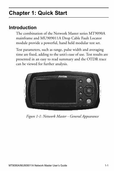
IntroductionThe combination of the Network Master series MT9090A mainframe and MU909011A Drop Cable Fault Locator module provide a powerful, hand held modular test set.
Test parameters, such as range, pulse width and averaging time are fixed, adding to the unit’s ease of use. Test results are presented in an easy to read summary and the OTDR trace can be viewed for further analysis.
Figure 1-1: Network Master - General Appearance
1-2 MT9090A/MU909011A Network Master User’s Guide
Basic ConfigurationThe basic configuration of the unit includes:
• MT9090A Mainframe• MU909011A Drop Cable Fault Locator module• AC charger/adapter• Ni-MH battery pack• 1 Optical Adapter• User’s Guide (operation manual)
Powering Up the UnitThe unit can be powered externally by using the AC charger/adapter (see “AC Charger/Adapter” on page 2-12) or internally by using the rechargeable Ni-MH (Nickel-Metal Hydride) battery pack (see “Installing the Ni-MH battery pack” on page 2-7). In the absence of either the AC charger/adapter or the rechargeable Ni-MH battery pack you can power the unit by using 4 AA Ni-MH batteries.
NoteNote
The AC charger/adapter used must be the one supplied by Anritsu with the Network Master. Use of another AC charger/adapter may result in damage to the unit and/or the Ni-MH battery pack.
Start Up Sequence1. Press the Menu/Power key .2. The unit performs a self-test during which the
Anritsu splash screen appears briefly, followed by the Network Master splash screen.
3. When the self-test is complete, the unit launches the the Fault Locate application at the Power Meter
MT9090A/MU909011A Network Master User’s Guide 1-3
Step screen, if the unit is equipped with the optional Power Meter.
If the unit does not have the optional Power Meter, either the Connection Check (if selected in the Preferences Setups) or the Fault Locate Step screen will appear.
Fault Locate ApplicationThe Fault Locate application provide a simple “Pass/Fail” test method. The test starts out at the Power Meter step. If the incoming power signal is above the current threshold setting, the fiber under test receives a “PASS” or “Over Range” rating and no further testing is required.
When the fiber under test receives a “FAIL” rating or if it is “Under Range”, follow the on-screen instructions as to how to proceed further with the Fault Locate step.
Test results are presented in an easy to read summary, as shown in Figure 1-2 on page 1-4 and the OTDR trace can be viewed for further analysis.
To perform a Fault Locate test:
• With the unit powered on, connect the fiber under test to the unit’s measurement port and then press the Start key to start a test. The test proceeds through the following steps:
Power Meter Step –
- On units with the optional Power Meter, the Power Meter Step perform a PASS/FAIL test of the incoming signal level of the fiber under test.
1-4 MT9090A/MU909011A Network Master User’s Guide
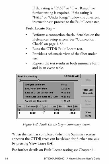
If the rating is “PASS” or “Over Range” no further testing is required. If the rating is “FAIL” or “Under Range” follow the on-screen instructions to proceed to the Fault Locate step.
Fault Locate Step –
- Performs a connection check, if enabled on the Preferences Setup screen. See “Connection Check” on page 4-38.
- Runs the OTDR Fault Locate test.- Provides a schematic view of the fiber under
test.- Reports the test results in both summary form
and in an event table.
Figure 1-2: Fault Locate Step – Summary screen
When the test has completed (when the Summary screen appears) the OTDR trace can be viewed for further analysis by pressing View Trace (F4).
For further details on Fault Locate testing see Chapter 4.
MT9090A/MU909011A Network Master User’s Guide 1-5
VFL TestingThe Visual Fault Locator (VFL) is a visible (red) light source. Since the light from the VFL is visible, it is useful for locating fault points in the dead zone by visually checking the diffusing light.
NoteNote
The VFL is an option – not all units are equipped with the VFL.
• With the fiber under test connected to the VFL port (see “Connecting Fiber to the VFL Port” on page 2-17), press the Menu/Power key to display the General Functions pop-up menu. When the pop up menu appears, press the Set key, the VFL control menu appears. Highlight the desired operating mode, CW or MOD, and press the Set key. Visually examine the fiber under test, locating the fault (bend or break) by finding the red glow.
• To turn off the VFL, press the Menu/Power key, the General Functions pop-up menu appears with VFL highlighted. Press the Set key , the VFL control menu appears, highlight OFF and press the Set key.
For further details on the VFL see “VFL (Visual Fault Locator)” on pages 3-6 through 3-8.
WARNING !
NEVER look directly into the cable connector on the Network Master nor into the end of a cable connected to the unit. If laser radiation enters the eye, there is a risk of injury.
1-6 MT9090A/MU909011A Network Master User’s Guide
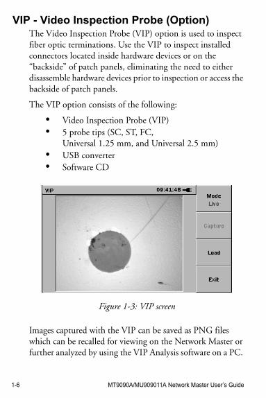
VIP - Video Inspection Probe (Option)The Video Inspection Probe (VIP) option is used to inspect fiber optic terminations. Use the VIP to inspect installed connectors located inside hardware devices or on the “backside” of patch panels, eliminating the need to either disassemble hardware devices prior to inspection or access the backside of patch panels.
The VIP option consists of the following:
• Video Inspection Probe (VIP)• 5 probe tips (SC, ST, FC,
Universal 1.25 mm, and Universal 2.5 mm)• USB converter• Software CD
Figure 1-3: VIP screen
Images captured with the VIP can be saved as PNG files which can be recalled for viewing on the Network Master or further analyzed by using the VIP Analysis software on a PC.
MT9090A/MU909011A Network Master User’s Guide 1-7
NoteNote
The Software CD contains the VIP Analysis software which is for PC use only. See the software’s help set for details on its use.
For further details on the Video Inspection Probe see Chapter 5, “Video Inspection Probe (VIP) Option”.

1-8 MT9090A/MU909011A Network Master User’s Guide
MT9090A/MU909011A Network Master User’s Guide 2-1
Chapter 2: Overview
It is important to become familiar with the layout of the Network Master. Three areas important to the use and function of the unit are the front panel, back panel, and the top connector panel.
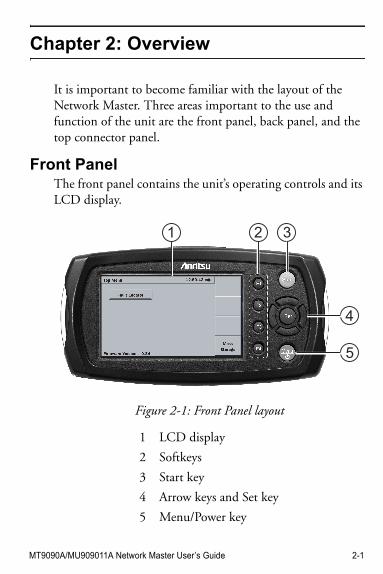
Front PanelThe front panel contains the unit’s operating controls and its LCD display.
Figure 2-1: Front Panel layout
1 LCD display
2 Softkeys
3 Start key
4 Arrow keys and Set key
5 Menu/Power key
2 31
4
5
2-2 MT9090A/MU909011A Network Master User’s Guide
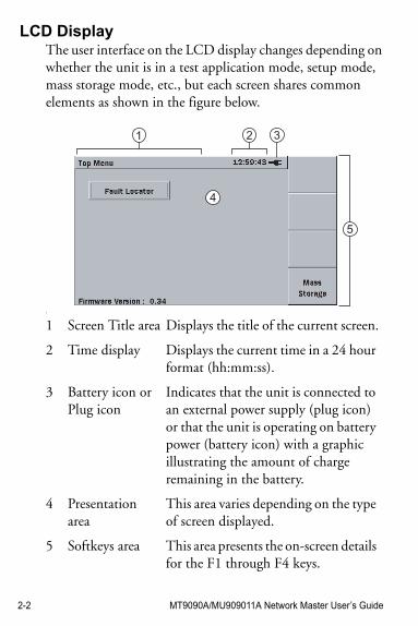
LCD DisplayThe user interface on the LCD display changes depending on whether the unit is in a test application mode, setup mode, mass storage mode, etc., but each screen shares common elements as shown in the figure below.
s
1 Screen Title area Displays the title of the current screen.
2 Time display Displays the current time in a 24 hour format (hh:mm:ss).
3 Battery icon or Plug icon
Indicates that the unit is connected to an external power supply (plug icon) or that the unit is operating on battery power (battery icon) with a graphic illustrating the amount of charge remaining in the battery.
4 Presentation area
This area varies depending on the type of screen displayed.
5 Softkeys area This area presents the on-screen details for the F1 through F4 keys.
21 3
4
5
MT9090A/MU909011A Network Master User’s Guide 2-3
Softkeys
Start Key
Arrow Keys and Set Key
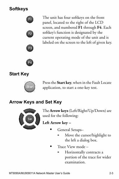
The unit has four softkeys on the front panel, located to the right of the LCD screen, and numbered F1 through F4. Each softkey’s function is designated by the current operating mode of the unit and is labeled on the screen to the left of given key.
Press the Start key, when in the Fault Locate application, to start a one-key test.
The Arrow keys (Left/Right/Up/Down) are used for the following:
Left Arrow key –
• General Setups–- Move the cursor/highlight to
the left a dialog box.
• Trace View mode –- Horizontally contracts a
portion of the trace for wider examination.
2-4 MT9090A/MU909011A Network Master User’s Guide
Right Arrow key –
• General Setups–- Move the cursor/highlight to
the right a dialog box.
• Trace View mode –- Horizontally expands a
portion of the trace for closer examination.
Up Arrow key –
• General Setups–- Press the Up Arrow key to
move to the next higher item in a pop-up menu.
• Trace View mode –- Vertically expands a portion
of the trace for closer examination.
Down Arrow key –
• General Setups–- Press the Down Arrow key to
move to the next lower item in a pop-up menu.
• Trace View mode –- Vertically contracts a portion
of the trace for wider examination.
MT9090A/MU909011A Network Master User’s Guide 2-5
Menu/Power Key
Back PanelThe back panel of the unit contains the battery compartment and a captive fastener used to secure the test module to the Network Master mainframe, as well as the various compliance and warning labels for the test module. In addition the model/serial number label for the test module is also located on the back panel (see item 4 in Figure 2-2 on page 2-6).
Set key –
• Setups (General and Application specific)- Press the Set key to select the
currently highlighted item in a pop-up menu or dialog box.
When the unit is powered off –
• Press the Menu/Power key to power up the unit.
When the unit is powered on –
• Press the Menu/Power key to display the pop-up menu for the current screen, if one is available.The Power Down selection is also accessed from the same pop-up menu.
2-6 MT9090A/MU909011A Network Master User’s Guide
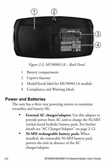
Figure 2-2: MU909011A – Back Panel
Power and BatteriesThe unit has a three way powering system to maximize versatility and battery life.
• External AC charger/adapter: Use this adapter to provide power from AC and to charge the Ni-MH (nickel-metal hydride) battery pack. For further details see “AC Charger/Adapter” on page 2-12.
• Ni-MH rechargeable battery pack: When installed, the removable Ni-MH battery pack powers the unit in absence of the AC charger/adapter.
1 Battery compartment
2 Captive fastener
3 Model/Serial label for MU909011A module
4 Compliance and Warning labels
1 2
3
4
MT9090A/MU909011A Network Master User’s Guide 2-7
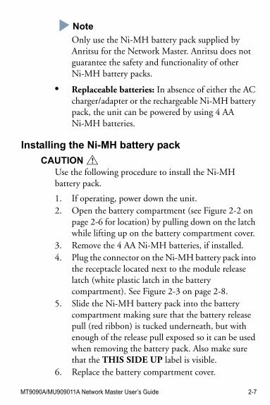
Note
Only use the Ni-MH battery pack supplied by Anritsu for the Network Master. Anritsu does not guarantee the safety and functionality of other Ni-MH battery packs.
• Replaceable batteries: In absence of either the AC charger/adapter or the rechargeable Ni-MH battery pack, the unit can be powered by using 4 AA Ni-MH batteries.
Installing the Ni-MH battery pack
CAUTION !Use the following procedure to install the Ni-MH battery pack.
1. If operating, power down the unit.2. Open the battery compartment (see Figure 2-2 on
page 2-6 for location) by pulling down on the latch while lifting up on the battery compartment cover.
3. Remove the 4 AA Ni-MH batteries, if installed.4. Plug the connector on the Ni-MH battery pack into
the receptacle located next to the module release latch (white plastic latch in the battery compartment). See Figure 2-3 on page 2-8.
5. Slide the Ni-MH battery pack into the battery compartment making sure that the battery release pull (red ribbon) is tucked underneath, but with enough of the release pull exposed so it can be used when removing the battery pack. Also make sure that the THIS SIDE UP label is visible.
6. Replace the battery compartment cover.
2-8 MT9090A/MU909011A Network Master User’s Guide
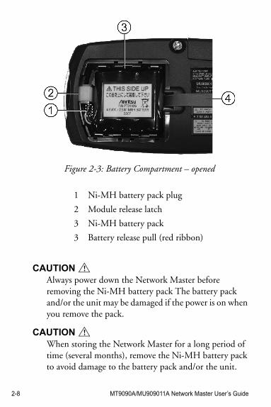
Figure 2-3: Battery Compartment – opened
CAUTION !Always power down the Network Master before removing the Ni-MH battery pack The battery pack and/or the unit may be damaged if the power is on when you remove the pack.
CAUTION !When storing the Network Master for a long period of time (several months), remove the Ni-MH battery pack to avoid damage to the battery pack and/or the unit.
1 Ni-MH battery pack plug
2 Module release latch
3 Ni-MH battery pack
3 Battery release pull (red ribbon)
MT9090A/MU909011A Network Master User’s Guide 2-9
Or, if storing the Network Master with the Ni-MH battery pack in place, make sure to recharge the unit periodically (every several months).
Battery Replacement – Ni-MH pack to AA Ni-MHUse the following procedure when replacing the Ni-MH battery pack with AA Ni-MH batteries:
1. If operating, power down the unit.2. Open the battery compartment (see Figure 2-2 on
page 2-6 for location) by pulling down on the latch while lifting up on the battery compartment cover.
3. Using the battery release pull, lift out the Ni-MH battery pack and unplug it from its receptacle located next to the module release latch (white plastic latch in the battery compartment).
4. Insert 4 new AA Ni-MH batteries in the compartment, following the polarity symbols next to the battery contacts.
5. Replace the battery compartment cover.
CAUTION !Always power down the unit before removing old AA Ni-MH batteries. If the batteries are removed with the power on, settings and data files could be lost.
CAUTION !Remove replaceable Ni-MH batteries from the unit when storing the unit for a long period of time (1 to 2 months).
Storing the unit for a long period of time with replaceable Ni-MH batteries in place will result in decreasing the discharge capacity of the batteries.
2-10 MT9090A/MU909011A Network Master User’s Guide
Bottom PanelThe bottom panel of the unit contains the model/serial number label for the mainframe.
Figure 2-4: Bottom Panel
Top Connector PanelThe top connector panel of the unit contains the measurement port used to connect optical fiber to the unit for Power Meter and Fault Locate testing, as well as USB ports for uploading and downloading files. The DC power connection and Battery Status LED are also located on the top panel.
The VFL port is available on units equipped with the Visual Fault Locator option.
Figure 2-5 on page 2-11 provides an example of a typical unit’s top panel.
NoteNote
The configuration of the top panel will vary depending on the optics and options installed in a given unit.
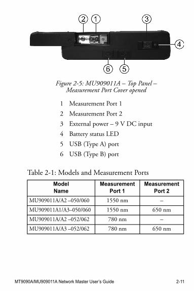
Table 2-1: Models and Measurement Ports
ModelName
Measurement Port 1
MeasurementPort 2
MT9090A/MU909011A Network Master User’s Guide 2-11
Figure 2-5: MU909011A – Top Panel – Measurement Port Cover opened
1 Measurement Port 1
2 Measurement Port 2
3 External power – 9 V DC input
4 Battery status LED
5 USB (Type A) port
6 USB (Type B) port
MU909011A/A2 –050/060 1550 nm –
MU909011A1/A3–050/060 1550 nm 650 nm
MU909011A/A2 –052/062 780 nm –
MU909011A/A3 –052/062 780 nm 650 nm
2-12 MT9090A/MU909011A Network Master User’s Guide
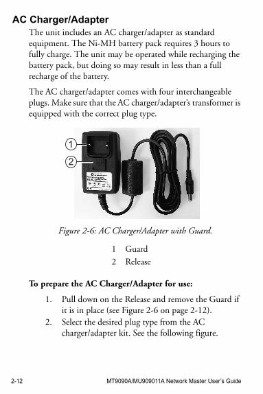
AC Charger/AdapterThe unit includes an AC charger/adapter as standard equipment. The Ni-MH battery pack requires 3 hours to fully charge. The unit may be operated while recharging the battery pack, but doing so may result in less than a full recharge of the battery.
The AC charger/adapter comes with four interchangeable plugs. Make sure that the AC charger/adapter’s transformer is equipped with the correct plug type.
Figure 2-6: AC Charger/Adapter with Guard.
To prepare the AC Charger/Adapter for use:
1. Pull down on the Release and remove the Guard if it is in place (see Figure 2-6 on page 2-12).
2. Select the desired plug type from the AC charger/adapter kit. See the following figure.
1 Guard
2 Release
1
2
MT9090A/MU909011A Network Master User’s Guide 2-13
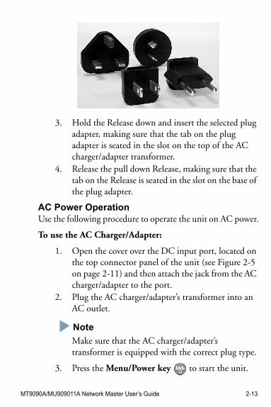
3. Hold the Release down and insert the selected plug adapter, making sure that the tab on the plug adapter is seated in the slot on the top of the AC charger/adapter transformer.
4. Release the pull down Release, making sure that the tab on the Release is seated in the slot on the base of the plug adapter.
AC Power OperationUse the following procedure to operate the unit on AC power.
To use the AC Charger/Adapter:
1. Open the cover over the DC input port, located on the top connector panel of the unit (see Figure 2-5 on page 2-11) and then attach the jack from the AC charger/adapter to the port.
2. Plug the AC charger/adapter’s transformer into an AC outlet.
Note
Make sure that the AC charger/adapter’s transformer is equipped with the correct plug type.
3. Press the Menu/Power key to start the unit.
2-14 MT9090A/MU909011A Network Master User’s Guide
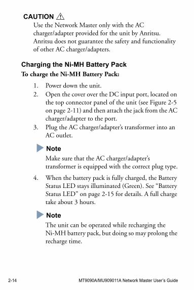
CAUTION !Use the Network Master only with the AC charger/adapter provided for the unit by Anritsu. Anritsu does not guarantee the safety and functionality of other AC charger/adapters.
Charging the Ni-MH Battery Pack
To charge the Ni-MH Battery Pack:
1. Power down the unit.2. Open the cover over the DC input port, located on
the top connector panel of the unit (see Figure 2-5 on page 2-11) and then attach the jack from the AC charger/adapter to the port.
3. Plug the AC charger/adapter’s transformer into an AC outlet.
Note
Make sure that the AC charger/adapter’s transformer is equipped with the correct plug type.
4. When the battery pack is fully charged, the Battery Status LED stays illuminated (Green). See “Battery Status LED” on page 2-15 for details. A full charge take about 3 hours.
Note
The unit can be operated while recharging the Ni-MH battery pack, but doing so may prolong the recharge time.
MT9090A/MU909011A Network Master User’s Guide 2-15
Battery Status LEDThe Battery Status LED displays the current status of the Ni-MH battery pack:
• Red – The battery pack has stopped charging. The following can cause the battery pack to stop charging:
- When starting to charge, the temperature of the battery pack is lower than 5°C or higher than 45°C.
In this situation, disconnect the AC adapter jack from the unit and wait until the temperature of the battery pack is within the 5°C to 45°C range.
- While charging, the temperature of the battery pack becomes lower than 5°C or higher than 60°C.
In this situation, charging will automatically resume once the temperature of the battery pack is within the 5°C to 45°C range.
- Charging has not finished, as it takes about 3 hours to fully charge the battery pack. To avoid overcharging, the unit stops charging after about 3 hours.
In this situation, disconnect AC adapter jack and then reconnect the jack to the unit.
If the Battery Status LED remains red, there is a problem with the battery pack. Please contact the Anritsu Technical Support Center or your local
2-16 MT9090A/MU909011A Network Master User’s Guide
Anritsu representative (see “Anritsu Corporation Contact” on page xix).
• Orange – The AC charger/adapter is plugged in and the battery pack is charging.
• Green – The AC charger/adapter is plugged in and the battery pack is refreshed. The battery pack will continue charging in maintenance charge mode. See the following Note.
Note
At the moment the LED turns Green, the battery pack will have approximately 85% capacity. A few hours of maintenance charge is sometimes required to bring the battery pack to 100% capacity. You may start a charge or discharge cycle at any time with minimal “memory” issues. The battery pack can be left in maintenance charge indefinitely.
MT9090A/MU909011A Network Master User’s Guide 2-17
VFL PortThe VFL port (see item 2 in Figure 2-5 on page 2-11) provides access to the optional Visual Fault Locator (VFL) function. This port is equipped with a 2.5 mm universal fiber connector adapter which accepts the ferrule of most standard fiber connectors.
NoteNote
See Table 2-1 on page 2-11 for details on which models are equipped with the VFL option.
Connecting Fiber to the VFL Port
To connect fiber to the Visual Fault Locator:
1. Slide the cover on the Measurement Port to the opened position. See Figure 2-5 on page 2-11.
2. Insert the ferrule of a connectorized fiber into the VFL port.
Measurement PortThe Measurement port (see item 1 in Figure 2-5 on page 2-11) is located on the top panel of the unit and is accessed by opening the sliding measurement port cover (see Figure 2-5 on page 2-11). This port, provides access for the Fault Locate application OTDR and the optional Optical Power Meter functions. The Measurement port is a universal optical connector, which requires an optical connector adapter.
Universal Optical Connector and Adapters
The optical connector adapter is an interface to the measurement port (OTDR port) for units equipped with a universal optical connector. Adapters for FC, SC, ST, LC, and
2-18 MT9090A/MU909011A Network Master User’s Guide
DIN fiber connector types are available. (Other connector adapter types may be available, contact Anritsu for details). Depending on the unit, the OTDR port is equipped with either a UPC or APC optical connector.
NoteNote
Units equipped with the APC optical connector require APC style optical adapters.
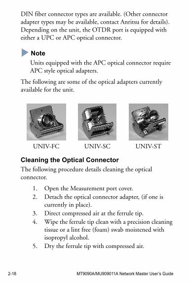
The following are some of the optical adapters currently available for the unit.
Cleaning the Optical Connector
The following procedure details cleaning the optical connector.
1. Open the Measurement port cover.2. Detach the optical connector adapter, (if one is
currently in place). 3. Direct compressed air at the ferrule tip.4. Wipe the ferrule tip clean with a precision cleaning
tissue or a lint free (foam) swab moistened with isopropyl alcohol.
5. Dry the ferrule tip with compressed air.
UNIV-FC UNIV-SC UNIV-ST
MT9090A/MU909011A Network Master User’s Guide 2-19
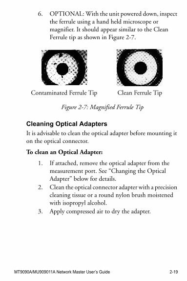
6. OPTIONAL: With the unit powered down, inspect the ferrule using a hand held microscope or magnifier. It should appear similar to the Clean Ferrule tip as shown in Figure 2-7.
Figure 2-7: Magnified Ferrule Tip
Cleaning Optical Adapters
It is advisable to clean the optical adapter before mounting it on the optical connector.
To clean an Optical Adapter:
1. If attached, remove the optical adapter from the measurement port. See “Changing the Optical Adapter” below for details.
2. Clean the optical connector adapter with a precision cleaning tissue or a round nylon brush moistened with isopropyl alcohol.
3. Apply compressed air to dry the adapter.
Contaminated Ferrule Tip Clean Ferrule Tip
2-20 MT9090A/MU909011A Network Master User’s Guide
Changing the Optical Adapter
CAUTION !Units equipped with angle-polished (APC) optical connectors require angle-polished optical adapters.
To change an Optical Adapter:
1. Open the cover on the measurement port.2. Lift up on the adapter’s locking lever. You will hear
a “click” when the latch mechanism disengages.3. Slide the adapter out of the measurement port.4. Slide the new adapter on to the connector ferrule in
the measurement port. 5. Push down on the adapter’s locking lever. You will
hear a “click” when the latch mechanism engages.
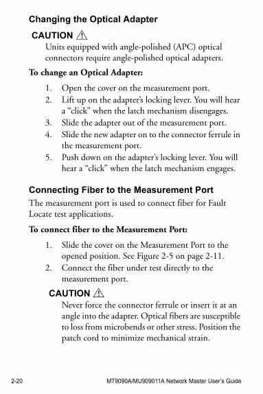
Connecting Fiber to the Measurement Port
The measurement port is used to connect fiber for Fault Locate test applications.
To connect fiber to the Measurement Port:
1. Slide the cover on the Measurement Port to the opened position. See Figure 2-5 on page 2-11.
2. Connect the fiber under test directly to the measurement port.
CAUTION !Never force the connector ferrule or insert it at an angle into the adapter. Optical fibers are susceptible to loss from microbends or other stress. Position the patch cord to minimize mechanical strain.
MT9090A/MU909011A Network Master User’s Guide 2-21
Connecting Peripheral DevicesThe unit comes equipped with two USB port, which allow a USB device or personal computer to be connected.
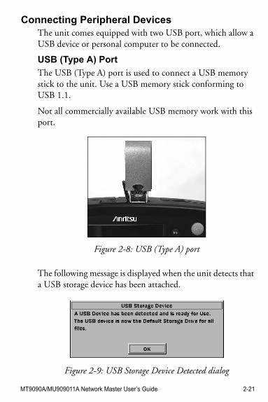
USB (Type A) Port
The USB (Type A) port is used to connect a USB memory stick to the unit. Use a USB memory stick conforming to USB 1.1.
Not all commercially available USB memory work with this port.
Figure 2-8: USB (Type A) port
The following message is displayed when the unit detects that a USB storage device has been attached.
Figure 2-9: USB Storage Device Detected dialog
2-22 MT9090A/MU909011A Network Master User’s Guide
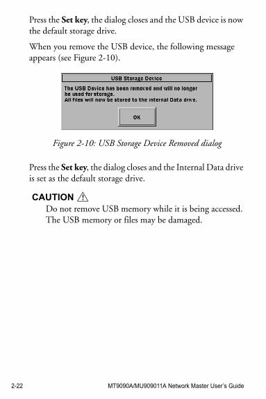
Press the Set key, the dialog closes and the USB device is now the default storage drive.
When you remove the USB device, the following message appears (see Figure 2-10).
Figure 2-10: USB Storage Device Removed dialog
Press the Set key, the dialog closes and the Internal Data drive is set as the default storage drive.
CAUTION !Do not remove USB memory while it is being accessed. The USB memory or files may be damaged.
MT9090A/MU909011A Network Master User’s Guide 2-23
USB (Type B) Port
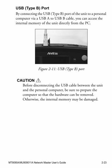
By connecting the USB (Type B) port of the unit to a personal computer via a USB A to USB B cable, you can access the internal memory of the unit directly from the PC.
Figure 2-11: USB (Type B) port
CAUTION !Before disconnecting the USB cable between the unit and the personal computer, be sure to prepare the computer so that the hardware can be removed. Otherwise, the internal memory may be damaged.
2-24 MT9090A/MU909011A Network Master User’s Guide
Changing the Test ModuleUse the following procedure to remove the current test module from the Network Master mainframe and install a new test module.
To change the test module:
1. Power down the unit, if current operating.2. Disconnect the AC charger/adapter, if currently
connected.3. Loosen the captive fastener on the back panel of the
current test module (see item 2 in Figure 2-2 on page 2-6). When fully loosened, the fastener slides out of, but remain attached to, the test module.
4. Open the battery compartment (see Figure 2-2 on page 2-6 for location) and remove the battery pack or AA Ni-MH batteries (if installed).
5. Hold down the module release latch (white plastic latch in the battery compartment – see item 2 in Figure 2-3 on page 2-8) while pulling forward on the Network Master mainframe to separate it from the test module. Let go of the module release latch after the Network Master mainframe separates from the test module.
CAUTION !The Network Master mainframe and test module fit together snugly. Use caution when removing the mainframe from the module.
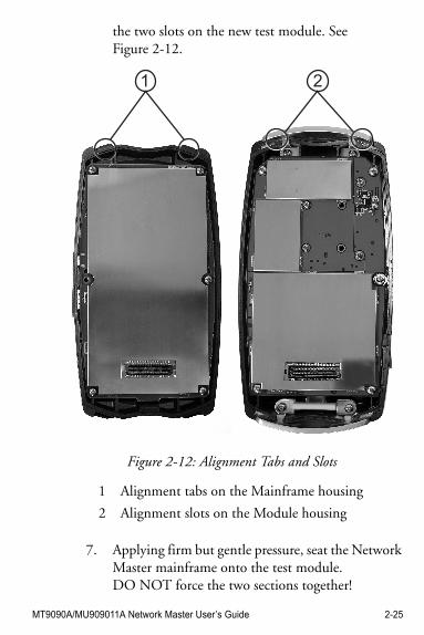
6. To install the new test module, align the 2 tabs on the back side of the Network Master mainframe (the end opposite of the 100 pin connector) with
MT9090A/MU909011A Network Master User’s Guide 2-25
the two slots on the new test module. See Figure 2-12.
Figure 2-12: Alignment Tabs and Slots
7. Applying firm but gentle pressure, seat the Network Master mainframe onto the test module. DO NOT force the two sections together!
1 Alignment tabs on the Mainframe housing
2 Alignment slots on the Module housing
1 2
2-26 MT9090A/MU909011A Network Master User’s Guide
8. Tighten the captive fastener.9. Replace the battery pack or AA Ni-MH batteries, if
removed in step 2.10. Replace the battery compartment cover.
Basic Notes on Use
CAUTION !
1. Measurement port cover
The Measurement port cover prevents dust and other contaminates from collecting on the measurement port. Keep this cover closed except when a cable is connected.
2. Condensation
Condensation may occur on the inside surface of the unit when it is carried into a room (high temperature) from an outdoor location (low temperature), etc. If this occurs, dry the unit thoroughly before turning on the power.
3. Temperature range
Use the unit within the operating temperature range(0 to +50°C) and storage temperature range (-20 to +60°C). If the unit is placed in a car or other enclosed space for a long time, the ambient temperature may exceed the specified range, resulting in malfunction of the unit.
MT9090A/MU909011A Network Master User’s Guide 2-27
For other notes on use, read the safety-related information in this manual thoroughly before use.
4. Safety
Do not use any AC charger/adapter or Ni-MH battery pack other than the one supplied. Otherwise, the unit may be damaged due to nonconformity with the specifications.
5. Laser
Never look directly into the cable connector on the equipment nor into the end of a cable connected to the equipment. If laser radiation enters the eye, there is a risk of injury.
In addition, the unit outputs high-power optical pulses. To prevent damage to the photoreceiving circuit of the communication device connected to the optical fiber to be measured, remove the communication device from the optical fiber before measurement. Anritsu will take no responsibility for damage to the communication or any other device.
6. Maintenance
Anritsu recommends that the unit be inspected once a year at the Anritsu Customer Service Center (a fee will be charged).

2-28 MT9090A/MU909011A Network Master User’s Guide
MT9090A/MU909011A Network Master User’s Guide 3-1
Chapter 3: General Operation andSystem Setups
General OperationThis section assumes that the battery pack is already charged or that the AC charger/adapter is connected to the unit.
Refer to the following sections for details on charging the battery pack or connecting the AC charger/adapter:
• “Charging the Ni-MH Battery Pack” on page 2-14• “AC Power Operation” on page 2-13
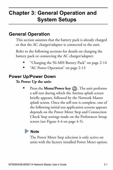
Power Up/Power DownTo Power Up the unit:
• Press the Menu/Power key . The unit preforms a self-test during which the Anritsu splash screen briefly appears, followed by the Network Master splash screen. Once the self-test is complete, one of the following initial test application screens appears depends on the Power Meter Step and Connection Check Step settings made on the Preferences Setup screen (see Figure 4-4 on page 4-5).
Note
The Power Meter Step selection is only active on units with the factory installed Power Meter option.
3-2 MT9090A/MU909011A Network Master User’s Guide
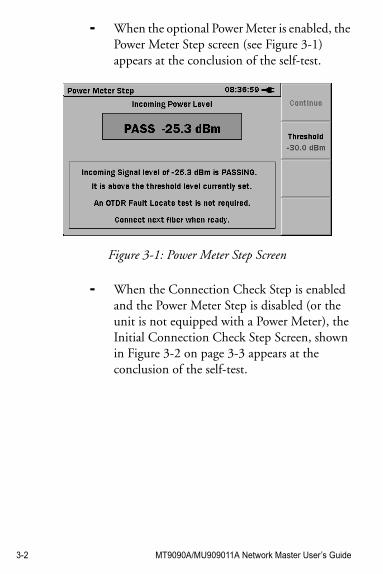
- When the optional Power Meter is enabled, the Power Meter Step screen (see Figure 3-1) appears at the conclusion of the self-test.
Figure 3-1: Power Meter Step Screen
- When the Connection Check Step is enabled and the Power Meter Step is disabled (or the unit is not equipped with a Power Meter), the Initial Connection Check Step Screen, shown in Figure 3-2 on page 3-3 appears at the conclusion of the self-test.
MT9090A/MU909011A Network Master User’s Guide 3-3
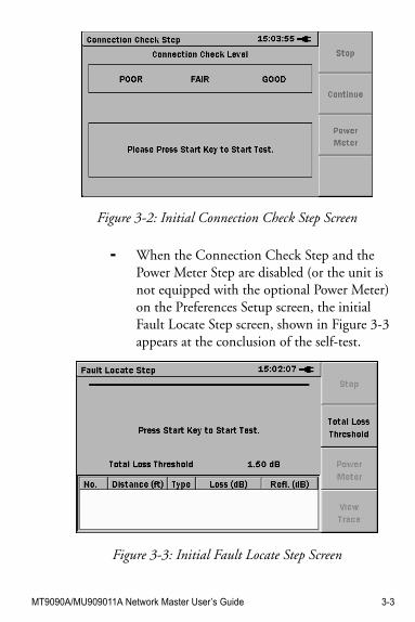
Figure 3-2: Initial Connection Check Step Screen
- When the Connection Check Step and the Power Meter Step are disabled (or the unit is not equipped with the optional Power Meter) on the Preferences Setup screen, the initial Fault Locate Step screen, shown in Figure 3-3 appears at the conclusion of the self-test.
Figure 3-3: Initial Fault Locate Step Screen
3-4 MT9090A/MU909011A Network Master User’s Guide
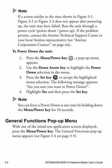
NoteNote
If a screen similar to the ones shown in Figure 3-1, Figure 3-2 or Figure 3-3 does not appear after powering up, the unit may have failed. Run the unit through a power cycle (power down / power up). If the problem persists, contact the Anritsu Technical Support Center or your local Arnitsu representative (see “Anritsu Corporation Contact” on page xix).
To Power Down the unit:
1. Press the Menu/Power key , a pop-up menu appears.
2. Use the Down Arrow key to highlight the Power Down selection in the menu.
3. Press the Set key to accept the highlighted menu selection. The following message appears: “Are you sure you want to Power Down?”.
4. Highlight Yes and then press the Set key.
NoteNote
You can force a Power Down at any time by holding down the Menu/Power key for 10 seconds.
General Functions Pop-up MenuWith one of the initial test application screens displayed, press the Menu/Power key. The General Functions pop-up menu appears (see Figure 3-4 on page 3-5).
MT9090A/MU909011A Network Master User’s Guide 3-5
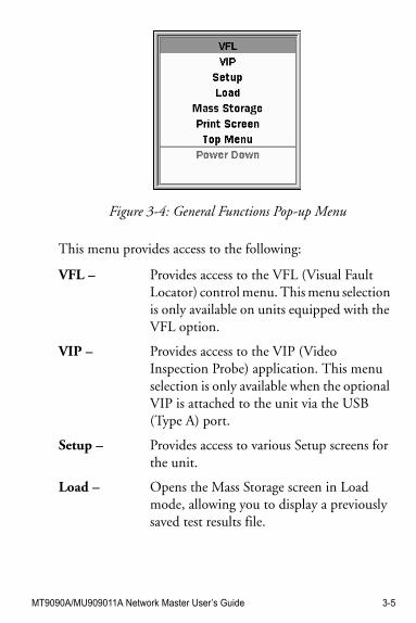
Figure 3-4: General Functions Pop-up Menu
This menu provides access to the following:
VFL – Provides access to the VFL (Visual Fault Locator) control menu. This menu selection is only available on units equipped with the VFL option.
VIP – Provides access to the VIP (Video Inspection Probe) application. This menu selection is only available when the optional VIP is attached to the unit via the USB (Type A) port.
Setup – Provides access to various Setup screens for the unit.
Load – Opens the Mass Storage screen in Load mode, allowing you to display a previously saved test results file.
3-6 MT9090A/MU909011A Network Master User’s Guide
VFL (Visual Fault Locator)The Visual Fault Locator (VFL) is a visible (red) light source. Since the light from the VFL is visible, it is useful for locating fault points in the dead zone by visually checking the diffusing light.
WARNING !
NEVER look directly into the cable connector on the unit nor into the end of a cable connected to the unit. If laser radiation enters the eye, there is a risk of injury.
NoteNote
The VFL is an option – not all units are equipped with the VFL.
Mass Storage – Opens the Mass Storage screen in File Operations mode, allowing you to copy, delete or rename files, as well as creating new folders.
Print Screen – Saves a screen capture of the current screen as a BMP file to the unit’s internal memory.
Top Menu – Accesses the Top Menu screen.
Help – Basic help information is available when in the Setup screens or the Top Menu screen. See “Help Function” on page 3-17.
Save – Accesses the Mass Storage Save Trace screen. See “Saving Files Manually” on page 4-41.
Power Down – Starts the power down sequence. See “To Power Down the unit:” on page 3-4 for details).
MT9090A/MU909011A Network Master User’s Guide 3-7
To use the Visual Fault Locator:
1. Connect a fiber to the VFL port (see “Connecting Fiber to the VFL Port” on page 2-17 for details).
2. With the unit powered up and the Fault Locate application active, press the Menu/Power key . The General Functions pop-up menu appears with VFL highlighted.
Note
The VFL selection is only available when one of the following screens is displayed: Power Meter Step (see Figure 3-1 on page 3-2), Connection Check Step (see Figure 3-2 on page 3-3), Initial Fault Locate Step (see Figure 3-3 on page 3-3), Fault Locate Summary (see Figure 4-15 on page 4-18) or Trace View (see Figure 4-20 on page 4-26).
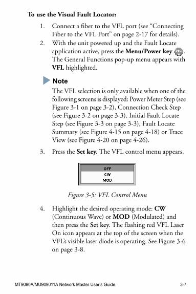
3. Press the Set key. The VFL control menu appears.
Figure 3-5: VFL Control Menu
4. Highlight the desired operating mode: CW (Continuous Wave) or MOD (Modulated) and then press the Set key. The flashing red VFL Laser On icon appears at the top of the screen when the VFL’s visible laser diode is operating. See Figure 3-6 on page 3-8.
3-8 MT9090A/MU909011A Network Master User’s Guide
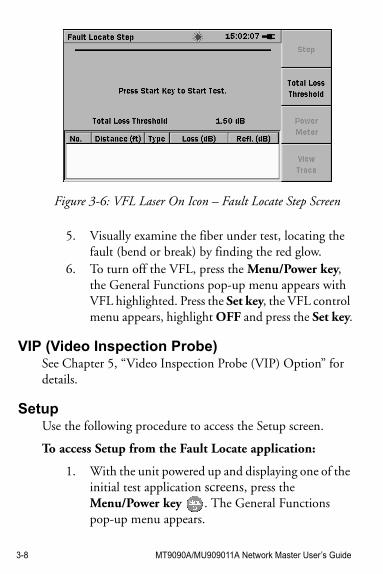
Figure 3-6: VFL Laser On Icon – Fault Locate Step Screen
5. Visually examine the fiber under test, locating the fault (bend or break) by finding the red glow.
6. To turn off the VFL, press the Menu/Power key, the General Functions pop-up menu appears with VFL highlighted. Press the Set key, the VFL control menu appears, highlight OFF and press the Set key.
VIP (Video Inspection Probe)See Chapter 5, “Video Inspection Probe (VIP) Option” for details.
SetupUse the following procedure to access the Setup screen.
To access Setup from the Fault Locate application:
1. With the unit powered up and displaying one of the initial test application screens, press the Menu/Power key . The General Functions pop-up menu appears.
MT9090A/MU909011A Network Master User’s Guide 3-9
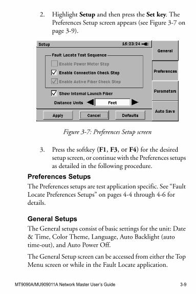
2. Highlight Setup and then press the Set key. The Preferences Setup screen appears (see Figure 3-7 on page 3-9).
Figure 3-7: Preferences Setup screen
3. Press the softkey (F1, F3, or F4) for the desired setup screen, or continue with the Preferences setups as detailed in the following procedure.
Preferences Setups
The Preferences setups are test application specific. See “Fault Locate Preferences Setups” on pages 4-4 through 4-6 for details.
General Setups
The General setups consist of basic settings for the unit: Date & Time, Color Theme, Language, Auto Backlight (auto time-out), and Auto Power Off.
The General Setup screen can be accessed from either the Top Menu screen or while in the Fault Locate application.
3-10 MT9090A/MU909011A Network Master User’s Guide
To set the General Setups from the Top Menu:
1. Access the Top Menu. See “To access the Top Menu:” on page 3-27 for details.
2. Press the Menu/Power key. A pop-up menu appears with the Setup selection highlighted.
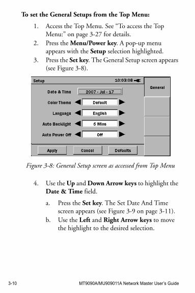
3. Press the Set key. The General Setup screen appears (see Figure 3-8).
Figure 3-8: General Setup screen as accessed from Top Menu
4. Use the Up and Down Arrow keys to highlight the Date & Time field.
a. Press the Set key. The Set Date And Time screen appears (see Figure 3-9 on page 3-11).
b. Use the Left and Right Arrow keys to move the highlight to the desired selection.
MT9090A/MU909011A Network Master User’s Guide 3-11
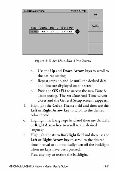
Figure 3-9: Set Date And Time Screen
c. Use the Up and Down Arrow keys to scroll to the desired setting.
d. Repeat steps 4b and 4c until the desired date and time are displayed on the screen.
e. Press the OK (F1) to accept the new Date & Time setting. The Set Date And Time screen closes and the General Setup screen reappears.
5. Highlight the Color Theme field and then use the Left or Right Arrow key to scroll to the desired color theme.
6. Highlight the Language field and then use the Left or Right Arrow key to scroll to the desired language.
7. Highlight the Auto Backlight field and then use the Left or Right Arrow key to scroll to the desired time interval to automatically turn off the backlight when no keys have been pressed. Press any key to restore the backlight.
3-12 MT9090A/MU909011A Network Master User’s Guide
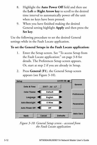
8. Highlight the Auto Power Off field and then use the Left or Right Arrow key to scroll to the desired time interval to automatically power off the unit when no keys have been pressed.
9. When you have finished making the desired General setting highlight Apply and then press the Set key.
Use the following procedure to set the desired General settings while in the Fault Locate application.
To set the General Setups in the Fault Locate application:
1. Enter the Setup screen. See “To access Setup from the Fault Locate application:” on page 3-8 for details. The Preferences Setup screen appears. Or, start at step 2 if you are already in Setup.
2. Press General (F1), the General Setup screen appears (see Figure 3-10).
Figure 3-10: General Setup screen - accessed from the Fault Locate application
MT9090A/MU909011A Network Master User’s Guide 3-13
3. Use the Up and Down Arrow keys to highlight the Date & Time field.
a. Press the Set key. The Set Date And Time screen appears (see Figure 3-9 on page 3-11).
b. Use the Left and Right Arrow keys to move the highlight to the desired selection.
c. Use the Up and Down Arrow keys to scroll to the desired setting.
d. Repeat steps 3b and 3c until the desired date and time are displayed in the dialog box.
e. Press the OK (F1) to accept the new Date & Time setting. The Set Date And Time screen closes and the General Setup screen reappears.
4. Highlight the Color Theme field and then use the Left or Right Arrow key to scroll to the desired color theme.
5. Highlight the Language field and then use the Left or Right Arrow key to scroll to the desired language.
6. Highlight the Auto Backlight field and then use the Left or Right Arrow key to scroll to the desired time interval to automatically turn off the backlight when no keys have been pressed. Press any key to restore the backlight.
7. Highlight the Auto Power Off field and then use the Left or Right Arrow key to scroll to the desired time interval to automatically power off the unit when no keys have been pressed.
8. When you have finished making the desired General setting:
3-14 MT9090A/MU909011A Network Master User’s Guide
- Use the Down Arrow key to move the highlight to the Apply button, and then press the Set key to close Setup.
Or –
- Select the softkey (F2, F3, or F4) for the next desired setup screen.
Parameters Setups
The Parameters setups are test application specific. See “Fault Locate Parameters Setups” on pages 4-7 through 4-9 for details.
Auto Save Setups
The Auto Save setups are test application specific. See “Auto Save Setups” on pages 4-9 through 4-12.
Set to DefaultsUse the following procedures to return the Setups to their factory default settings.
NoteNote
If you enter Setup from the Top Menu screen, only the General setups will be set to the factory defaults. To reset the Setup defaults for a specific test application, launch the given test application and then enter Setup.
To reset the General Setup defaults from the Top Menu:
1. Enter the Top Menu screen. See “Top Menu” on page 3-27 for details.
2. Press the Menu/Power key.
MT9090A/MU909011A Network Master User’s Guide 3-15
3. Highlight Setup on the pop-up menu and then press the Set key. The General Setup screen appears.
4. Highlight Defaults and press the Set key.
Note
As of the current software release, the Auto Backlight and Auto Power Off parameters are the only General Setup parameters re-set via the Defaults button.
5. Highlight Apply and then press the Set key. The General setup defaults are now set and the Top Menu screen reappears.
To return the Fault Locate application defaults:
1. With the Fault Locate application active, press the Menu/Power key.
2. Highlight Setup on the pop-up menu and then press the Set key. The initial setup screen for the application appears.
3. Highlight Defaults and press the Set key. The all setup screens for the application now display their default setting.
Note
As of the current software release, the Auto Backlight and Auto Power Off parameters are the only General Setup parameters re-set via the Defaults button.
4. Highlight Apply and then press the Set key. All of the setup defaults are now applied and the unit returns to the test application.
3-16 MT9090A/MU909011A Network Master User’s Guide
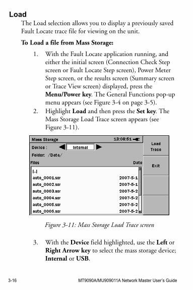
LoadThe Load selection allows you to display a previously saved Fault Locate trace file for viewing on the unit.
To Load a file from Mass Storage:
1. With the Fault Locate application running, and either the initial screen (Connection Check Step screen or Fault Locate Step screen), Power Meter Step screen, or the results screen (Summary screen or Trace View screen) displayed, press the Menu/Power key. The General Functions pop-up menu appears (see Figure 3-4 on page 3-5).
2. Highlight Load and then press the Set key. The Mass Storage Load Trace screen appears (see Figure 3-11).
Figure 3-11: Mass Storage Load Trace screen
3. With the Device field highlighted, use the Left or Right Arrow key to select the mass storage device; Internal or USB.
MT9090A/MU909011A Network Master User’s Guide 3-17
If there is no USB device attached to the unit, the device selection is automatically set to Internal.
4. If the file is in the currently displayed folder/directory continue at step 5.
Or –
If the file is not in the currently displayed folder/directory, navigate to the desired folder/directory and then continue at step 5.
5. Highlight the desired file and then press Load Trace (F1). The Load screen closes and the selected trace is displayed.
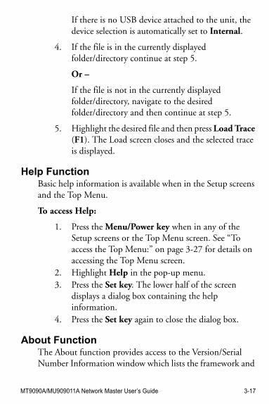
Help FunctionBasic help information is available when in the Setup screens and the Top Menu.
To access Help:
1. Press the Menu/Power key when in any of the Setup screens or the Top Menu screen. See “To access the Top Menu:” on page 3-27 for details on accessing the Top Menu screen.
2. Highlight Help in the pop-up menu.3. Press the Set key. The lower half of the screen
displays a dialog box containing the help information.
4. Press the Set key again to close the dialog box.
About FunctionThe About function provides access to the Version/Serial Number Information window which lists the framework and
3-18 MT9090A/MU909011A Network Master User’s Guide
test application software version levels, as well as the serial numbers for the Mainframe and Module.
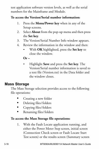
To access the Version/Serial number information:
1. Press the Menu/Power key when in any of the Setup screens.
2. Select About from the pop-up menu and then press the Set key.
3. The Version/Serial Number Info window appears.4. Review the information in the window and then:
- With OK highlighted, press the Set key to close the window.
Or –
- Highlight Save and press the Set key. The Version/Serial number information is saved to a text file (Version.txt) in the Data folder and the window closes.
Mass StorageThe Mass Storage selection provides access to the following file operations:
• Creating a new folder• Deleting files / folders• Copying files / folders• Renaming files / folders
To access the Mass Storage file operations:
1. With the Fault Locate application running, and either the Power Meter Step screen, initial screen (Connection Check screen or Fault Locate Start Test screen) or the results screen (Summary screen
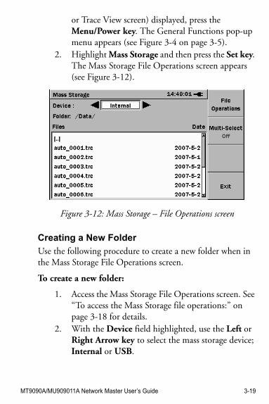
MT9090A/MU909011A Network Master User’s Guide 3-19
or Trace View screen) displayed, press the Menu/Power key. The General Functions pop-up menu appears (see Figure 3-4 on page 3-5).
2. Highlight Mass Storage and then press the Set key. The Mass Storage File Operations screen appears (see Figure 3-12).
Figure 3-12: Mass Storage – File Operations screen
Creating a New Folder
Use the following procedure to create a new folder when in the Mass Storage File Operations screen.
To create a new folder:
1. Access the Mass Storage File Operations screen. See “To access the Mass Storage file operations:” on page 3-18 for details.
2. With the Device field highlighted, use the Left or Right Arrow key to select the mass storage device; Internal or USB.
3-20 MT9090A/MU909011A Network Master User’s Guide
If there is no USB device attached to the unit, the device selection is automatically set to Internal.
3. Select the directory/folder in which the new folder is to be located.Or –
Continue at step 4 if you are not selecting a different directory/folder.
4. Press File Operations (F1). The File Operations pop-up menu appears with the New Folder selection highlighted.
5. Press the Set key. The pop-up menu closes and a folder named [newFolder] is added to the current directory.
Deleting a File or Folder
Use the following procedure to delete a file or folder when in the Mass Storage File Operations screen.
To delete a file or folder:
1. Access the Mass Storage File Operations screen. See “To access the Mass Storage file operations:” on page 3-18 for details.
2. With the Device field highlighted, use the Left or Right Arrow key to select the mass storage device; Internal or USB.If there is no USB device attached to the unit, the device selection is automatically set to Internal.
3. Navigate to and highlight the desired file or folder.4. Press File Operations (F1). The File Operations
pop-up menu appears.
MT9090A/MU909011A Network Master User’s Guide 3-21
5. Highlight Delete and then press the Set key.6. The Confirm Delete dialog appears, Select Yes and
then press the Set key.
The dialog closes and the file or folder is deleted from the currently displayed directory.
Deleting Multiple Files or Folders
Use the following procedure to delete multiple files or folders when in the Mass Storage File Operations screen.
To delete multiple files or folders:
1. Access the Mass Storage File Operations screen. See “To access the Mass Storage file operations:” on page 3-18 for details.
2. With the Device field highlighted, use the Left or Right Arrow key to select the mass storage device; Internal or USB.If there is no USB device attached to the unit, the device selection is automatically set to Internal.
3. Navigate to the desired directory or folder.4. Press Multi-Select Off (F2). The red legend on the
softkey changes to “On” and a blank check box is displayed before each filename in the current directory or folder.
5. Highlight the first file or folder to delete and then press the Set key. A checkmark appears in the check box for the highlighted item. Repeat until all the desired files or folders are selected and continue at step 6.
Or –
3-22 MT9090A/MU909011A Network Master User’s Guide
To select all of the files in the current folder or all of the folders in the current directory; press File Operations (F1), highlight Select All, press the Set key and then continue at step 6.
6. Press File Operations (F1) and then highlight Delete in the pop-up menu.
7. Press the Set key. The Confirm Delete dialog appears.
8. Select Yes and then press the Set key. The selected files or folders are deleted.
9. Press Exit (F4) to close the Mass Storage screen.
Copying a File or Folder
Use the following procedure to copy a file or folder when in the Mass Storage File Operations screen.
To copy a file or folder:
1. Access the Mass Storage File Operations screen. See “To access the Mass Storage file operations:” on page 3-18 for details.
2. With the Device field highlighted, use the Left or Right Arrow key to select the mass storage device; Internal or USB.If there is no USB device attached to the unit, the device selection is automatically set to Internal.
3. Navigate to and highlight the desired file or folder.4. Press File Operations (F1). The File Operations
pop-up menu appears.5. Highlight Copy and then press the Set key. The
Destination window is superimposed over the Mass Storage File Operations screen (see Figure 3-13 on page 3-23).
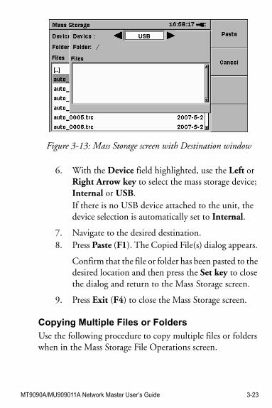
MT9090A/MU909011A Network Master User’s Guide 3-23
Figure 3-13: Mass Storage screen with Destination window
6. With the Device field highlighted, use the Left or Right Arrow key to select the mass storage device; Internal or USB.If there is no USB device attached to the unit, the device selection is automatically set to Internal.
7. Navigate to the desired destination.8. Press Paste (F1). The Copied File(s) dialog appears.
Confirm that the file or folder has been pasted to the desired location and then press the Set key to close the dialog and return to the Mass Storage screen.
9. Press Exit (F4) to close the Mass Storage screen.
Copying Multiple Files or Folders
Use the following procedure to copy multiple files or folders when in the Mass Storage File Operations screen.
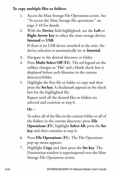
3-24 MT9090A/MU909011A Network Master User’s Guide
To copy multiple files or folders:
1. Access the Mass Storage File Operations screen. See “To access the Mass Storage file operations:” on page 3-18 for details.
2. With the Device field highlighted, use the Left or Right Arrow key to select the mass storage device; Internal or USB.If there is no USB device attached to the unit, the device selection is automatically set to Internal.
3. Navigate to the desired directory or folder.4. Press Multi-Select Off (F2). The red legend on the
softkey changes to “On” and a blank check box is displayed before each filename in the current directory/folder.
5. Highlight the first file or folder to copy and then press the Set key. A checkmark appears in the check box for the highlighted file. Repeat until all the desired files or folders are selected and continue at step 6.
Or –
To select all of the files in the current folder or all of the folders in the current directory; press File Operations (F1), highlight Select All, press the Set key and then continue at step 6.
6. Press File Operations (F1). The File Operations pop-up menu appears.
7. Highlight Copy and then press the Set key. The Destination window is superimposed over the Mass Storage File Operations screen.
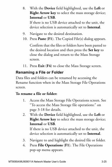
MT9090A/MU909011A Network Master User’s Guide 3-25
8. With the Device field highlighted, use the Left or Right Arrow key to select the mass storage device; Internal or USB.If there is no USB device attached to the unit, the device selection is automatically set to Internal.
9. Navigate to the desired destination.10. Press Paste (F1). The Copied File(s) dialog appears.
Confirm that the files or folders have been pasted to the desired location and then press the Set key to close the dialog and return to the Mass Storage screen.
11. Press Exit (F4) to close the Mass Storage screen.
Renaming a File or Folder
Data files and folders can be renamed by accessing the Rename function when in the Mass Storage File Operations screen.
To rename a file or folder:
1. Access the Mass Storage File Operations screen. See “To access the Mass Storage file operations:” on page 3-18 for details.
2. With the Device field highlighted, use the Left or Right Arrow key to select the mass storage device; Internal or USB.If there is no USB device attached to the unit, the device selection is automatically set to Internal.
3. Navigate to and highlight the desired file or folder.4. Press File Operations (F1). The File Operations
pop-up menu appears.
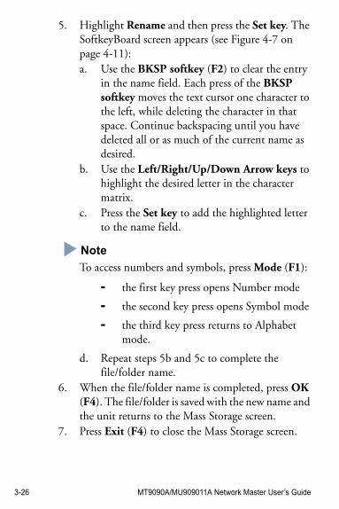
3-26 MT9090A/MU909011A Network Master User’s Guide
5. Highlight Rename and then press the Set key. The SoftkeyBoard screen appears (see Figure 4-7 on page 4-11):a. Use the BKSP softkey (F2) to clear the entry
in the name field. Each press of the BKSP softkey moves the text cursor one character to the left, while deleting the character in that space. Continue backspacing until you have deleted all or as much of the current name as desired.
b. Use the Left/Right/Up/Down Arrow keys to highlight the desired letter in the character matrix.
c. Press the Set key to add the highlighted letter to the name field.
Note
To access numbers and symbols, press Mode (F1):
- the first key press opens Number mode
- the second key press opens Symbol mode
- the third key press returns to Alphabet mode.
d. Repeat steps 5b and 5c to complete the file/folder name.
6. When the file/folder name is completed, press OK (F4). The file/folder is saved with the new name and the unit returns to the Mass Storage screen.
7. Press Exit (F4) to close the Mass Storage screen.
MT9090A/MU909011A Network Master User’s Guide 3-27
Print ScreenUse the Print Screen function to save the image on test result screens and most setup screens to a bitmap (bmp) file. The bmp files are saved to the Internal Data directory.
To save a Print Screen file:
1. With the desired screen displayed, press the Menu/Power key. The General Functions pop-up menu appears.
Note
If a pop-up menu is not displayed, the Print Screen function is not available for the currently displayed screen.
2. Highlight Print Screen and then press the Set key. 3. The Print Screen Complete dialog box appears in
about 2 to 3 seconds. Press the Set key to save the bmp file to the Data folder of the unit’s Internal memory.
Top MenuUse the Top Menu to select the current test application for units that provide two or more applications. In addition, the Top Menu also provide an alternate access to both the General Setup screen and the Mass Storage screen.
To access the Top Menu:
1. With the Fault Locate application running and one of the following screens displayed: Power Meter Step, Connection Check Step, Fault Locate Step or Trace View, press the Menu/Power key. The
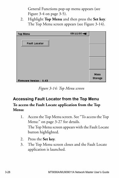
3-28 MT9090A/MU909011A Network Master User’s Guide
General Functions pop-up menu appears (see Figure 3-4 on page 3-5).
2. Highlight Top Menu and then press the Set key. The Top Menu screen appears (see Figure 3-14).
Figure 3-14: Top Menu screen
Accessing Fault Locator from the Top Menu
To access the Fault Locate application from the Top Menu:
1. Access the Top Menu screen. See “To access the Top Menu:” on page 3-27 for details.The Top Menu screen appears with the Fault Locate button highlighted.
2. Press the Set key. 3. The Top Menu screen closes and the Fault Locate
application is launched.
MT9090A/MU909011A Network Master User’s Guide 3-29
Access Mass Storage from the Top Menu
To access mass storage from the Top Menu:
1. Access the Top Menu screen. See “To access the Top Menu:” on page 3-27 for details.
2. Press Mass Storage (F4). The Mass Storage screen appears. See “Mass Storage” on pages 3-18 through 3-26 for details on the various mass storage file operations.

3-30 MT9090A/MU909011A Network Master User’s Guide
MT9090A/MU909011A Network Master User’s Guide 4-1
Chapter 4: Fault Locate Application
OverviewThe Fault Locate application provide a simple “Pass/Fail” test method. The test starts out at the Power Meter Step, providing that the unit is equipped with the optional Power Meter. If the incoming power signal is above the current threshold setting, the fiber under test receives a “PASS” rating and no further testing is required.
When the fiber under test receives a “FAIL” rating or if it is “Under Range”, follow the on-screen instructions for details on how to proceed further with the test.
Starting the Fault Locate ApplicationWith the fiber under test connected to the unit’s measurement port, starting Fault Locate application proceeds through the following:
• Performs a “Pass/Fail” test (on units with the optional Power Meter only)
• Performs a connection check (if enabled in Setup)• Runs the test• Reports the test results in both summary form and
in an event table.
To start the Fault Locate application:
1. Press the Menu/Power key . 2. The unit performs a self-test during which the
Anritsu splash screen appears briefly, followed by the Network Master splash screen.
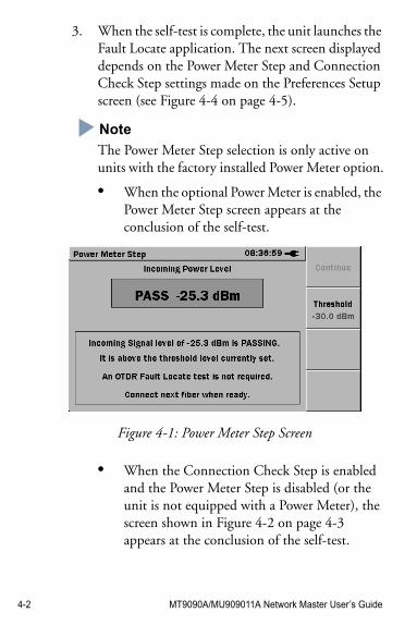
4-2 MT9090A/MU909011A Network Master User’s Guide
3. When the self-test is complete, the unit launches the Fault Locate application. The next screen displayed depends on the Power Meter Step and Connection Check Step settings made on the Preferences Setup screen (see Figure 4-4 on page 4-5).
Note
The Power Meter Step selection is only active on units with the factory installed Power Meter option.
• When the optional Power Meter is enabled, the Power Meter Step screen appears at the conclusion of the self-test.
Figure 4-1: Power Meter Step Screen
• When the Connection Check Step is enabled and the Power Meter Step is disabled (or the unit is not equipped with a Power Meter), the screen shown in Figure 4-2 on page 4-3 appears at the conclusion of the self-test.
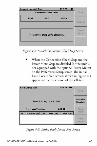
MT9090A/MU909011A Network Master User’s Guide 4-3
Figure 4-2: Initial Connection Check Step Screen
• When the Connection Check Step and the Power Meter Step are disabled (or the unit is not equipped with the optional Power Meter) on the Preferences Setup screen, the initial Fault Locate Step screen, shown in Figure 4-3 appears at the conclusion of the self-test.
Figure 4-3: Initial Fault Locate Step Screen
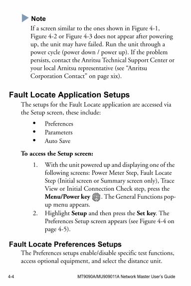
4-4 MT9090A/MU909011A Network Master User’s Guide
NoteNote
If a screen similar to the ones shown in Figure 4-1, Figure 4-2 or Figure 4-3 does not appear after powering up, the unit may have failed. Run the unit through a power cycle (power down / power up). If the problem persists, contact the Anritsu Technical Support Center or your local Arnitsu representative (see “Anritsu Corporation Contact” on page xix).
Fault Locate Application SetupsThe setups for the Fault Locate application are accessed via the Setup screen, these include:
• Preferences• Parameters• Auto Save
To access the Setup screen:
1. With the unit powered up and displaying one of the following screens: Power Meter Step, Fault Locate Step (Initial screen or Summary screen only), Trace View or Initial Connection Check step, press the Menu/Power key . The General Functions pop-up menu appears.
2. Highlight Setup and then press the Set key. The Preferences Setup screen appears (see Figure 4-4 on page 4-5).
Fault Locate Preferences SetupsThe Preferences setups enable/disable specific test functions, access optional equipment, and select the distance unit.
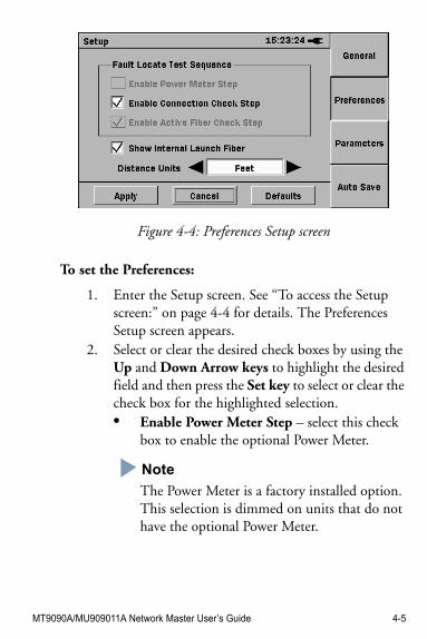
MT9090A/MU909011A Network Master User’s Guide 4-5
Figure 4-4: Preferences Setup screen
To set the Preferences:
1. Enter the Setup screen. See “To access the Setup screen:” on page 4-4 for details. The Preferences Setup screen appears.
2. Select or clear the desired check boxes by using the Up and Down Arrow keys to highlight the desired field and then press the Set key to select or clear the check box for the highlighted selection.• Enable Power Meter Step – select this check
box to enable the optional Power Meter.
Note
The Power Meter is a factory installed option. This selection is dimmed on units that do not have the optional Power Meter.
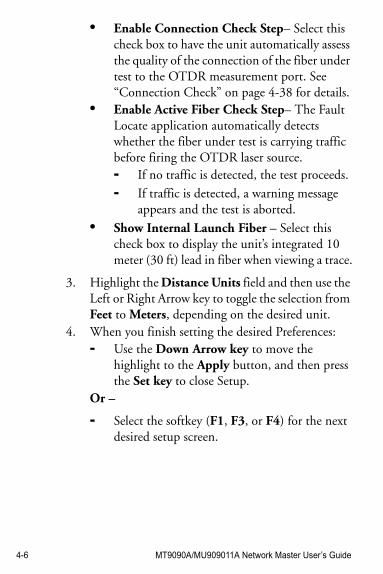
4-6 MT9090A/MU909011A Network Master User’s Guide
• Enable Connection Check Step– Select this check box to have the unit automatically assess the quality of the connection of the fiber under test to the OTDR measurement port. See “Connection Check” on page 4-38 for details.
• Enable Active Fiber Check Step– The Fault Locate application automatically detects whether the fiber under test is carrying traffic before firing the OTDR laser source.- If no traffic is detected, the test proceeds.
- If traffic is detected, a warning message appears and the test is aborted.
• Show Internal Launch Fiber – Select this check box to display the unit’s integrated 10 meter (30 ft) lead in fiber when viewing a trace.
3. Highlight the Distance Units field and then use the Left or Right Arrow key to toggle the selection from Feet to Meters, depending on the desired unit.
4. When you finish setting the desired Preferences: - Use the Down Arrow key to move the
highlight to the Apply button, and then press the Set key to close Setup.
Or –
- Select the softkey (F1, F3, or F4) for the next desired setup screen.
MT9090A/MU909011A Network Master User’s Guide 4-7
General SetupsThe General setups consist of settings common to all Network Master applications: Date & Time, Color Theme, Language, Auto Backlight (auto time-out) and Auto Power Off.
See “To set the General Setups in the Fault Locate application:” on page 3-12 for details.
Fault Locate Parameters SetupsUse the Parameters setups to set the thresholds used to determine the End/Fault Distance as well as the events reported in the Event Table on the Fault Locate Summary screen. In addition, set the IOR (Index of Refraction) and BSC (Backscatter Coefficient) values for the fiber under test.
Use the following procedure to establish the desired Parameters settings
To set the Parameters:
1. Enter the Setup screen. See “To access the Setup screen:” on page 4-4 for details. The Preferences Setup screen appears. Or, start at step 2 if you are already in Setup.
2. Press Parameters (F3), the Parameters Setup screen appears (see Figure 4-5 on page 4-8).
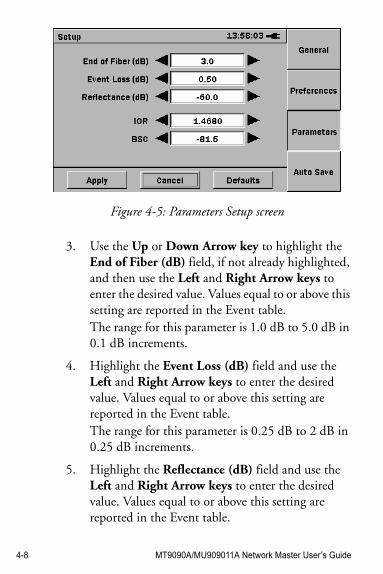
4-8 MT9090A/MU909011A Network Master User’s Guide
Figure 4-5: Parameters Setup screen
3. Use the Up or Down Arrow key to highlight the End of Fiber (dB) field, if not already highlighted, and then use the Left and Right Arrow keys to enter the desired value. Values equal to or above this setting are reported in the Event table.The range for this parameter is 1.0 dB to 5.0 dB in 0.1 dB increments.
4. Highlight the Event Loss (dB) field and use the Left and Right Arrow keys to enter the desired value. Values equal to or above this setting are reported in the Event table.The range for this parameter is 0.25 dB to 2 dB in 0.25 dB increments.
5. Highlight the Reflectance (dB) field and use the Left and Right Arrow keys to enter the desired value. Values equal to or above this setting are reported in the Event table.
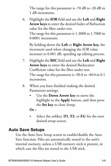
MT9090A/MU909011A Network Master User’s Guide 4-9
The range for this parameter is -70 dB to -20 dB in 1 dB increments.
6. Highlight the IOR field and use the Left and Right Arrow keys to enter the desired Index of Refraction value for the fiber under test.The range for this parameter is 1.3000 to 1.7000 in 0.0001 increments.
By holding down the Left or Right Arrow key, the increment used when changing the IOR value increases to 0.001 dB, speeding up editing process.
7. Highlight the BSC field and use the Left and Right Arrow keys to enter the desired Backscatter Coefficient value for the fiber under test.The range for this parameter is -90.0 to -40.0 in 0.1 increments.
8. When you have finished making the desired Parameters settings: - Use the Down Arrow key to move the
highlight to the Apply button, and then press the Set key to close Setup.
Or –
- Select the softkey (F1, F2, or F4) for the next desired setup screen.
Auto Save SetupsUse the Auto Save Setup screen to enable/disable the Auto Save function. Files are automatically stored to the unit’s internal memory, unless a USB memory stick is present, in which case the files are stored to the USB stick.
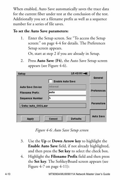
4-10 MT9090A/MU909011A Network Master User’s Guide
When enabled, Auto Save automatically saves the trace data for the current fiber under test at the conclusion of the test. Additionally you set a filename prefix as well as a sequence number for a series of file saves.
To set the Auto Save parameters:
1. Enter the Setup screen. See “To access the Setup screen:” on page 4-4 for details. The Preferences Setup screen appears. Or, start at step 2 if you are already in Setup.
2. Press Auto Save (F4), the Auto Save Setup screen appears (see Figure 4-6).
Figure 4-6: Auto Save Setup screen
3. Use the Up or Down Arrow key to highlight the Enable Auto Save field, if not already highlighted, and then press the Set key to select the check box.
4. Highlight the Filename Prefix field and then press the Set key. The SoftkeyBoard screen appears (see Figure 4-7 on page 4-11):
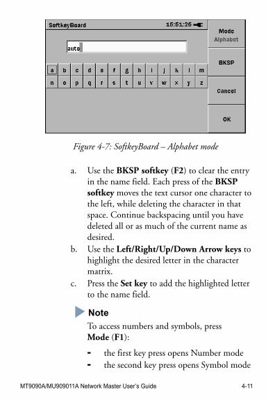
MT9090A/MU909011A Network Master User’s Guide 4-11
Figure 4-7: SoftkeyBoard – Alphabet mode
a. Use the BKSP softkey (F2) to clear the entry in the name field. Each press of the BKSP softkey moves the text cursor one character to the left, while deleting the character in that space. Continue backspacing until you have deleted all or as much of the current name as desired.
b. Use the Left/Right/Up/Down Arrow keys to highlight the desired letter in the character matrix.
c. Press the Set key to add the highlighted letter to the name field.
Note
To access numbers and symbols, press Mode (F1):
- the first key press opens Number mode- the second key press opens Symbol mode
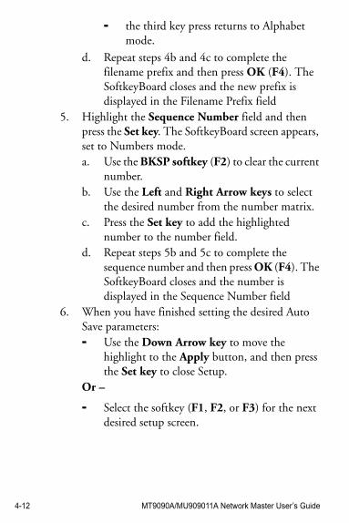
4-12 MT9090A/MU909011A Network Master User’s Guide
- the third key press returns to Alphabet mode.
d. Repeat steps 4b and 4c to complete the filename prefix and then press OK (F4). The SoftkeyBoard closes and the new prefix is displayed in the Filename Prefix field
5. Highlight the Sequence Number field and then press the Set key. The SoftkeyBoard screen appears, set to Numbers mode.a. Use the BKSP softkey (F2) to clear the current
number.b. Use the Left and Right Arrow keys to select
the desired number from the number matrix.c. Press the Set key to add the highlighted
number to the number field.d. Repeat steps 5b and 5c to complete the
sequence number and then press OK (F4). The SoftkeyBoard closes and the number is displayed in the Sequence Number field
6. When you have finished setting the desired Auto Save parameters: - Use the Down Arrow key to move the
highlight to the Apply button, and then press the Set key to close Setup.
Or –
- Select the softkey (F1, F2, or F3) for the next desired setup screen.
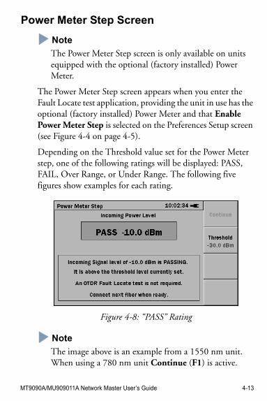
MT9090A/MU909011A Network Master User’s Guide 4-13
Power Meter Step Screen
NoteNote
The Power Meter Step screen is only available on units equipped with the optional (factory installed) Power Meter.
The Power Meter Step screen appears when you enter the Fault Locate test application, providing the unit in use has the optional (factory installed) Power Meter and that Enable Power Meter Step is selected on the Preferences Setup screen (see Figure 4-4 on page 4-5).
Depending on the Threshold value set for the Power Meter step, one of the following ratings will be displayed: PASS, FAIL, Over Range, or Under Range. The following five figures show examples for each rating.
Figure 4-8: “PASS” Rating
NoteNote
The image above is an example from a 1550 nm unit. When using a 780 nm unit Continue (F1) is active.
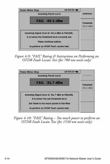
4-14 MT9090A/MU909011A Network Master User’s Guide
Figure 4-9: “FAIL” Rating & Instructions on Performing an OTDR Fault Locate Test (for 780 nm units only)
Figure 4-10: “FAIL” Rating – Too much power to perform an OTDR Fault Locate Test (for 1550 nm units only)
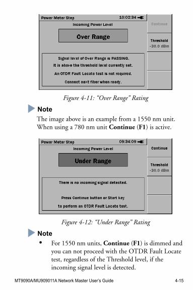
MT9090A/MU909011A Network Master User’s Guide 4-15
Figure 4-11: “Over Range” Rating
NoteNote
The image above is an example from a 1550 nm unit. When using a 780 nm unit Continue (F1) is active.
Figure 4-12: “Under Range” Rating
NoteNote
• For 1550 nm units, Continue (F1) is dimmed and you can not proceed with the OTDR Fault Locate test, regardless of the Threshold level, if the incoming signal level is detected.
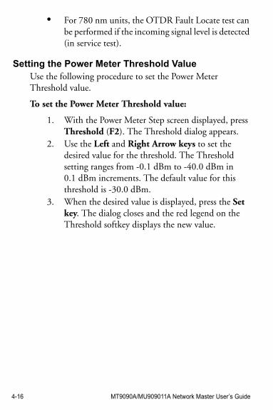
4-16 MT9090A/MU909011A Network Master User’s Guide
• For 780 nm units, the OTDR Fault Locate test can be performed if the incoming signal level is detected (in service test).
Setting the Power Meter Threshold ValueUse the following procedure to set the Power Meter Threshold value.
To set the Power Meter Threshold value:
1. With the Power Meter Step screen displayed, press Threshold (F2). The Threshold dialog appears.
2. Use the Left and Right Arrow keys to set the desired value for the threshold. The Threshold setting ranges from -0.1 dBm to -40.0 dBm in 0.1 dBm increments. The default value for this threshold is -30.0 dBm.
3. When the desired value is displayed, press the Set key. The dialog closes and the red legend on the Threshold softkey displays the new value.
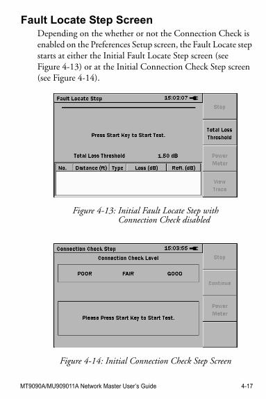
MT9090A/MU909011A Network Master User’s Guide 4-17
Fault Locate Step ScreenDepending on the whether or not the Connection Check is enabled on the Preferences Setup screen, the Fault Locate step starts at either the Initial Fault Locate Step screen (see Figure 4-13) or at the Initial Connection Check Step screen (see Figure 4-14).
Figure 4-13: Initial Fault Locate Step with Connection Check disabled
Figure 4-14: Initial Connection Check Step Screen
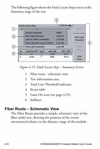
4-18 MT9090A/MU909011A Network Master User’s Guide
The following figure shows the Fault Locate Step screen at the Summary stage of the test.
Figure 4-15: Fault Locate Step – Summary Screen
Fiber Route – Schematic ViewThe Fiber Route provides a simple, schematic view of the fiber under test, showing the position of the events encountered relative to the distance range of the module.
1 Fiber route - schematic view
2 Test information area
3 Total Loss Threshold indicator
4 Event table
5 Laser On icon (see page 4-25)
6 Softkeys
1
2
4
3
5
6
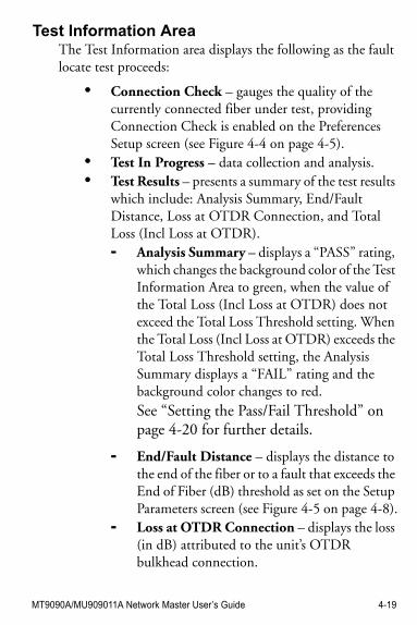
MT9090A/MU909011A Network Master User’s Guide 4-19
Test Information AreaThe Test Information area displays the following as the fault locate test proceeds:
• Connection Check – gauges the quality of the currently connected fiber under test, providing Connection Check is enabled on the Preferences Setup screen (see Figure 4-4 on page 4-5).
• Test In Progress – data collection and analysis.• Test Results – presents a summary of the test results
which include: Analysis Summary, End/Fault Distance, Loss at OTDR Connection, and Total Loss (Incl Loss at OTDR).- Analysis Summary – displays a “PASS” rating,
which changes the background color of the Test Information Area to green, when the value of the Total Loss (Incl Loss at OTDR) does not exceed the Total Loss Threshold setting. When the Total Loss (Incl Loss at OTDR) exceeds the Total Loss Threshold setting, the Analysis Summary displays a “FAIL” rating and the background color changes to red. See “Setting the Pass/Fail Threshold” on page 4-20 for further details.
- End/Fault Distance – displays the distance to the end of the fiber or to a fault that exceeds the End of Fiber (dB) threshold as set on the Setup Parameters screen (see Figure 4-5 on page 4-8).
- Loss at OTDR Connection – displays the loss (in dB) attributed to the unit’s OTDR bulkhead connection.
4-20 MT9090A/MU909011A Network Master User’s Guide
- Total Loss (Incl Loss at OTDR) – displays the total loss for the fiber under test in dB, including the Loss at OTDR Connection (initial loss at the OTDR bulkhead connection) and all events that meet or exceed the Event Loss (dB) threshold as set on the Setup Parameters screen (see Figure 4-5 on page 4-8).
Total Loss Threshold IndicatorDisplays the current value set for the Total Loss Threshold.
Setting the Pass/Fail Threshold
To set the Pass/Fail threshold:
1. Press Total Loss Threshold (F2). The Total Loss Threshold field appears.
2. Use the Left or Right Arrow key to scroll to the desired threshold setting. This setting ranges from 0.1 dB to 5.0 dB in 0.1 dB increments.
3. When the desired threshold setting is displayed in the Threshold field, press the Set key. The field closes and the Total Loss Threshold indicator displays the new threshold setting.
Event TableIn fiber analysis an “event” is considered to be a distinct deviation from normal fiber attenuation that may be introduced by a lossy connection (microbend, connector, or splice), a reflective connection (connector or fiber break), macrobend, or the end of the fiber. Only events that meet one or more of the set threshold criteria will be reported in the
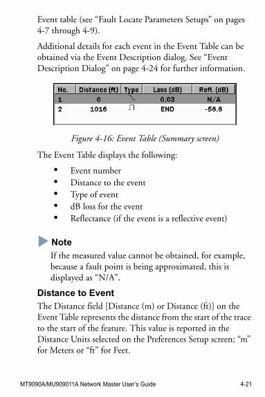
MT9090A/MU909011A Network Master User’s Guide 4-21
Event table (see “Fault Locate Parameters Setups” on pages 4-7 through 4-9).
Additional details for each event in the Event Table can be obtained via the Event Description dialog. See “Event Description Dialog” on page 4-24 for further information.
Figure 4-16: Event Table (Summary screen)
The Event Table displays the following:
• Event number• Distance to the event• Type of event• dB loss for the event• Reflectance (if the event is a reflective event)
NoteNote
If the measured value cannot be obtained, for example, because a fault point is being approximated, this is displayed as “N/A”.
Distance to Event
The Distance field [Distance (m) or Distance (ft)] on the Event Table represents the distance from the start of the trace to the start of the feature. This value is reported in the Distance Units selected on the Preferences Setup screen; “m” for Meters or “ft” for Feet.
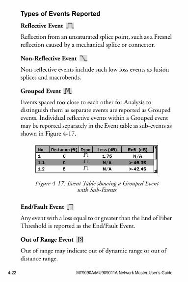
4-22 MT9090A/MU909011A Network Master User’s Guide
Types of Events Reported
Reflective Event
Reflection from an unsaturated splice point, such as a Fresnel reflection caused by a mechanical splice or connector.
Non-Reflective Event
Non-reflective events include such low loss events as fusion splices and macrobends.
Grouped Event
Events spaced too close to each other for Analysis to distinguish them as separate events are reported as Grouped events. Individual reflective events within a Grouped event may be reported separately in the Event table as sub-events as shown in Figure 4-17.
Figure 4-17: Event Table showing a Grouped Event with Sub-Events
End/Fault Event
Any event with a loss equal to or greater than the End of Fiber Threshold is reported as the End/Fault Event.
Out of Range Event
Out of range may indicate out of dynamic range or out of distance range.
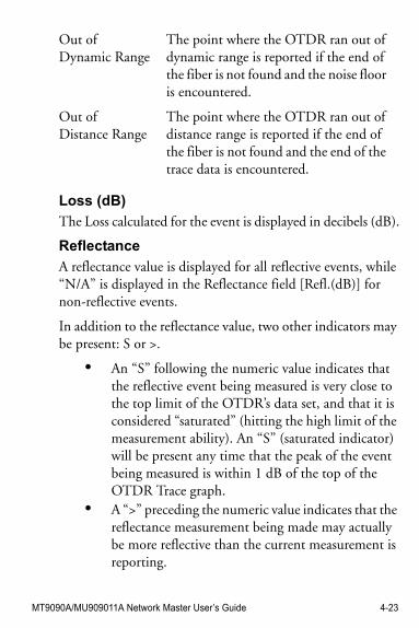
MT9090A/MU909011A Network Master User’s Guide 4-23
Loss (dB)
The Loss calculated for the event is displayed in decibels (dB).
Reflectance
A reflectance value is displayed for all reflective events, while “N/A” is displayed in the Reflectance field [Refl.(dB)] for non-reflective events.
In addition to the reflectance value, two other indicators may be present: S or >.
• An “S” following the numeric value indicates that the reflective event being measured is very close to the top limit of the OTDR’s data set, and that it is considered “saturated” (hitting the high limit of the measurement ability). An “S” (saturated indicator) will be present any time that the peak of the event being measured is within 1 dB of the top of the OTDR Trace graph.
• A “>” preceding the numeric value indicates that the reflectance measurement being made may actually be more reflective than the current measurement is reporting.
Out of Dynamic Range
The point where the OTDR ran out of dynamic range is reported if the end of the fiber is not found and the noise floor is encountered.
Out of Distance Range
The point where the OTDR ran out of distance range is reported if the end of the fiber is not found and the end of the trace data is encountered.
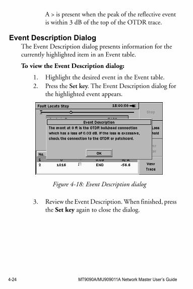
4-24 MT9090A/MU909011A Network Master User’s Guide
A > is present when the peak of the reflective event is within 3 dB of the top of the OTDR trace.
Event Description DialogThe Event Description dialog presents information for the currently highlighted item in an Event table.
To view the Event Description dialog:
1. Highlight the desired event in the Event table.2. Press the Set key. The Event Description dialog for
the highlighted event appears.
Figure 4-18: Event Description dialog
3. Review the Event Description. When finished, press the Set key again to close the dialog.
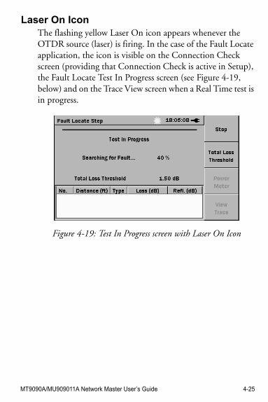
MT9090A/MU909011A Network Master User’s Guide 4-25
Laser On IconThe flashing yellow Laser On icon appears whenever the OTDR source (laser) is firing. In the case of the Fault Locate application, the icon is visible on the Connection Check screen (providing that Connection Check is active in Setup), the Fault Locate Test In Progress screen (see Figure 4-19, below) and on the Trace View screen when a Real Time test is in progress.
Figure 4-19: Test In Progress screen with Laser On Icon
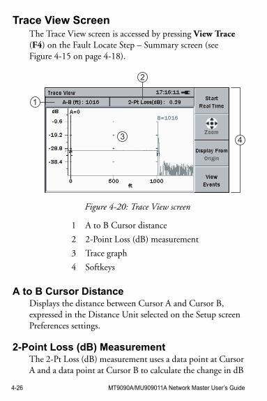
4-26 MT9090A/MU909011A Network Master User’s Guide
Trace View ScreenThe Trace View screen is accessed by pressing View Trace (F4) on the Fault Locate Step – Summary screen (see Figure 4-15 on page 4-18).
Figure 4-20: Trace View screen
A to B Cursor DistanceDisplays the distance between Cursor A and Cursor B, expressed in the Distance Unit selected on the Setup screen Preferences settings.
2-Point Loss (dB) MeasurementThe 2-Pt Loss (dB) measurement uses a data point at Cursor A and a data point at Cursor B to calculate the change in dB
1 A to B Cursor distance
2 2-Point Loss (dB) measurement
3 Trace graph
4 Softkeys
1
3 4
2
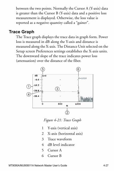
MT9090A/MU909011A Network Master User’s Guide 4-27
between the two points. Normally the Cursor A (Y-axis) data is greater than the Cursor B (Y-axis) data and a positive loss measurement is displayed. Otherwise, the loss value is reported as a negative quantity called a “gainer”.
Trace GraphThe Trace graph displays the trace data in graph form. Power loss is measured in dB along the Y-axis and distance is measured along the X-axis. The Distance Unit selected on the Setup screen Preferences settings establishes the X-axis units. The downward slope of the trace indicates power loss (attenuation) over the distance of the fiber.
Figure 4-21: Trace Graph
1 Y-axis (vertical axis)
2 X-axis (horizontal axis)
3 Trace waveform
4 dB level indicator
5 Cursor A
6 Cursor B
13
5 6
2
4
4-28 MT9090A/MU909011A Network Master User’s Guide
Trace Waveform
The Trace Waveform (or Trace) is the downward sloping line going from left to right that connects the data points collected during a test. See item 3 in Figure 4-21 on page 4-27.
Cursors
The cursors (see Figure 4-21 on page 4-27) are two vertical lines that extend from the top to the bottom of the trace graph. The cursors allow you to extract power and distance information from the trace graph. The active cursor is displayed in red and the inactive cursor is displayed in blue. The cursor distance is attached to each cursor. Distance readout value is determined by the Distance Unit selected in the Preferences setups. The distance readout reverses when a cursor movement causes it to come to close to the edge of the display.
See “Selecting and Positioning Cursors” on page 4-31 for details on cursor use.
dB Level Indicator
The dB level indicator (see item 4 in Figure 4-21 on page 4-27) denotes the intersection of the active cursor and the trace level.
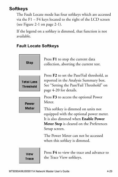
MT9090A/MU909011A Network Master User’s Guide 4-29
SoftkeysThe Fault Locate mode has four softkeys which are accessed via the F1 – F4 keys located to the right of the LCD screen (see Figure 2-1 on page 2-1).
If the legend on a softkey is dimmed, that function is not available.
Fault Locate Softkeys
Press F1 to stop the current data collection, aborting the current test.
Press F2 to set the Pass/Fail threshold, as reported in the Analysis Summary box. See “Setting the Pass/Fail Threshold” on page 4-20 for details.
Press F3 to access the optional Power Meter.
This softkey is dimmed on units not equipped with the optional power meter. It is also dimmed when Enable Power Meter Step is cleared on the Preferences Setup screen.
The Power Meter can not be accessed when this softkey is dimmed.
Press F4 to view the trace and advance to the Trace View softkeys.
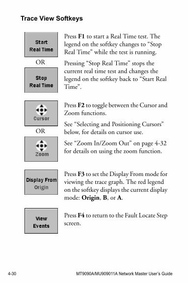
4-30 MT9090A/MU909011A Network Master User’s Guide
Trace View Softkeys
OR
Press F1 to start a Real Time test. The legend on the softkey changes to “Stop Real Time” while the test is running.
Pressing “Stop Real Time” stops the current real time test and changes the legend on the softkey back to “Start Real Time”.
OR
Press F2 to toggle between the Cursor and Zoom functions.
See “Selecting and Positioning Cursors” below, for details on cursor use.
See “Zoom In/Zoom Out” on page 4-32 for details on using the zoom function.
Press F3 to set the Display From mode for viewing the trace graph. The red legend on the softkey displays the current display mode: Origin, B, or A.
Press F4 to return to the Fault Locate Step screen.
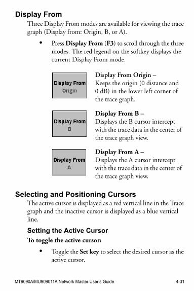
MT9090A/MU909011A Network Master User’s Guide 4-31
Display FromThree Display From modes are available for viewing the trace graph (Display from: Origin, B, or A).
• Press Display From (F3) to scroll through the three modes. The red legend on the softkey displays the current Display From mode.
Selecting and Positioning CursorsThe active cursor is displayed as a red vertical line in the Trace graph and the inactive cursor is displayed as a blue vertical line.
Setting the Active Cursor
To toggle the active cursor:
• Toggle the Set key to select the desired cursor as the active cursor.
Display From Origin –Keeps the origin (0 distance and 0 dB) in the lower left corner of the trace graph.
Display From B –Displays the B cursor intercept with the trace data in the center of the trace graph view.
Display From A –Displays the A cursor intercept with the trace data in the center of the trace graph view.
4-32 MT9090A/MU909011A Network Master User’s Guide
Positioning the Active Cursor
To position the active cursor:
1. Select the desired cursor (see “Setting the Active Cursor” on page 4-31 for details).
2. Toggle Display From (F3) to the desired mode, Display From B or Display From A, depending on the cursor selected in step 1.
3. Use the Left and Right Arrow keys to position the active cursor to the desired location. Each keypress move the cursor one pixel in the selected direction or hold down the desired arrow key to scroll the cursor.It may be necessary to zoom in on the trace for accurate positioning of the cursors. See “Zoom In/Zoom Out” below, for details.
Zoom In/Zoom OutUse the Zoom function to help make precise cursor placements or for closer examination of a portion of the trace waveform.
To zoom in:
1. Place the desired cursor (A or B) at the approximate position.
2. Toggle Display From (F3) to the desired mode, Display From B or Display From A, depending on the cursor selected in step 1.
3. Set F2 to “Zoom”.4. Press the Up Arrow key. Each key press decreases
the dB/division value of the vertical axis (Y-axis) by a factor of two.
MT9090A/MU909011A Network Master User’s Guide 4-33
Press the Right Arrow key. Each key press decreases the distance/division value of the horizontal axis (X-axis) by a factor of two.
To zoom out:
• Press the Down Arrow key. Each key press increases the dB/division value of the vertical axis (Y-axis) by a factor of two.
• Press the Left Arrow key. Each key press increases the distance/division value of the horizontal axis (X-axis) by a factor of two.
4-34 MT9090A/MU909011A Network Master User’s Guide
Fault Locate TestTo run the Fault Locate test application:
1. Connect the fiber to be tested to the measurement port (see “Connecting Fiber to the Measurement Port” on page 2-20 for details).
2. Power up the unit. The unit performs a self-test and then launches the Fault Locate application.The next screen displayed depends on the Power Meter Step and Connection Check Step settings made on the Preferences Setup screen (see Figure 4-4 on page 4-5).
Note
The Power Meter Step (step 3) only applies to units with the factory installed Power Meter option.
3. Power Meter Step –Depending on the Theshold value set for the Power Meter step (see “Setting the Power Meter Threshold Value” on page 4-16 for details), the Power Meter Step screen will display one of the following ratings: PASS, FAIL, Over Range, or Under Range.
• If the rating is “PASS” or “Over Range” no further testing is required.
• If the rating is “FAIL” or “Under Range”, press Continue (F1), to proceed to the Fault Locate step.
Note
• For 1550 nm units, Continue (F1) is dimmed and you can not proceed with the OTDR Fault
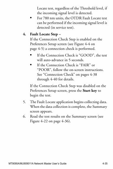
MT9090A/MU909011A Network Master User’s Guide 4-35
Locate test, regardless of the Threshold level, if the incoming signal level is detected.
• For 780 nm units, the OTDR Fault Locate test can be performed if the incoming signal level is detected (in service test).
4. Fault Locate Step –If the Connection Check Step is enabled on the Preferences Setup screen (see Figure 4-4 on page 4-5) a connection check is performed.
• If the Connection Check is “GOOD”, the test will auto-advance in 5 seconds.
• If the Connection Check is “FAIR” or “POOR”, follow the on-screen instructions. See “Connection Check” on pages 4-38 through 4-40 for details.
If the Connection Check Step was disabled on the Preferences Setup screen, press the Start key to begin the test.
5. The Fault Locate application begins collecting data. When the data collection is complete, the Summary screen appears.
6. Read the test results on the Summary screen (see Figure 4-22 on page 4-36).
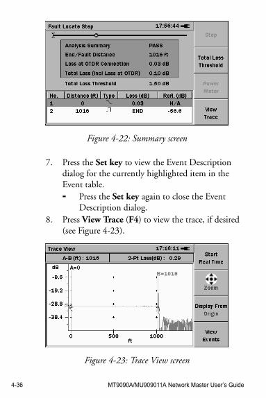
4-36 MT9090A/MU909011A Network Master User’s Guide
Figure 4-22: Summary screen
7. Press the Set key to view the Event Description dialog for the currently highlighted item in the Event table.- Press the Set key again to close the Event
Description dialog.8. Press View Trace (F4) to view the trace, if desired
(see Figure 4-23).
Figure 4-23: Trace View screen
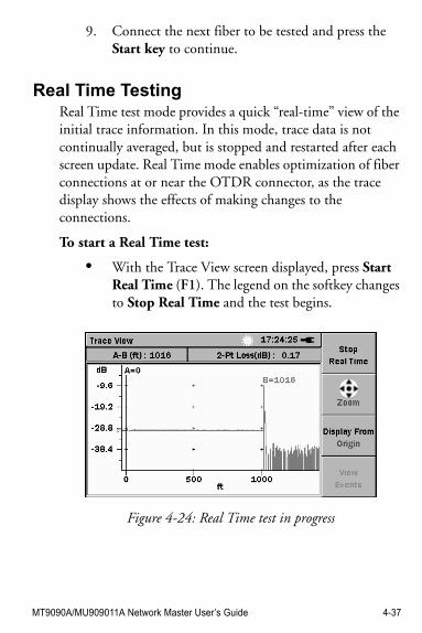
MT9090A/MU909011A Network Master User’s Guide 4-37
9. Connect the next fiber to be tested and press the Start key to continue.
Real Time TestingReal Time test mode provides a quick “real-time” view of the initial trace information. In this mode, trace data is not continually averaged, but is stopped and restarted after each screen update. Real Time mode enables optimization of fiber connections at or near the OTDR connector, as the trace display shows the effects of making changes to the connections.
To start a Real Time test:
• With the Trace View screen displayed, press Start Real Time (F1). The legend on the softkey changes to Stop Real Time and the test begins.
Figure 4-24: Real Time test in progress
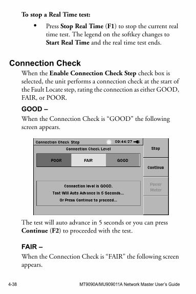
4-38 MT9090A/MU909011A Network Master User’s Guide
To stop a Real Time test:
• Press Stop Real Time (F1) to stop the current real time test. The legend on the softkey changes to Start Real Time and the real time test ends.
Connection CheckWhen the Enable Connection Check Step check box is selected, the unit performs a connection check at the start of the Fault Locate step, rating the connection as either GOOD, FAIR, or POOR.
GOOD –
When the Connection Check is “GOOD” the following screen appears.
The test will auto advance in 5 seconds or you can press Continue (F2) to proceeded with the test.
FAIR –
When the Connection Check is “FAIR” the following screen appears.
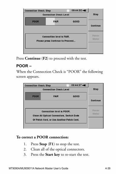
MT9090A/MU909011A Network Master User’s Guide 4-39
Press Continue (F2) to proceed with the test.
POOR –
When the Connection Check is “POOR” the following screen appears.
To correct a POOR connection:
1. Press Stop (F1) to stop the test.2. Clean all of the optical connectors.3. Press the Start key to re-start the test.
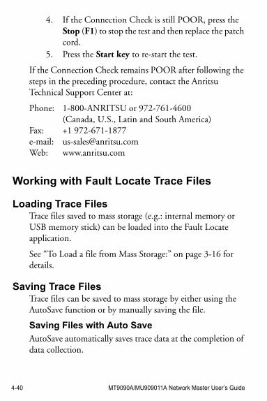
4-40 MT9090A/MU909011A Network Master User’s Guide
4. If the Connection Check is still POOR, press the Stop (F1) to stop the test and then replace the patch cord.
5. Press the Start key to re-start the test.
If the Connection Check remains POOR after following the steps in the preceding procedure, contact the Anritsu Technical Support Center at:
Phone: 1-800-ANRITSU or 972-761-4600(Canada, U.S., Latin and South America)
Fax: +1 972-671-1877e-mail: [email protected]: www.anritsu.com
Working with Fault Locate Trace Files
Loading Trace FilesTrace files saved to mass storage (e.g.: internal memory or USB memory stick) can be loaded into the Fault Locate application.
See “To Load a file from Mass Storage:” on page 3-16 for details.
Saving Trace FilesTrace files can be saved to mass storage by either using the AutoSave function or by manually saving the file.
Saving Files with Auto Save
AutoSave automatically saves trace data at the completion of data collection.
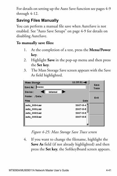
MT9090A/MU909011A Network Master User’s Guide 4-41
For details on setting up the Auto Save function see pages 4-9 through 4-12.
Saving Files Manually
You can perform a manual file save when AutoSave is not enabled. See “Auto Save Setups” on page 4-9 for details on disabling AutoSave.
To manually save files:
1. At the completion of a test, press the Menu/Power key.
2. Highlight Save in the pop-up menu and then press the Set key.
3. The Mass Storage Save screen appears with the Save As field highlighted.
Figure 4-25: Mass Storage Save Trace screen
4. If you want to change the filename, highlight the Save As field (if not already highlighted) and then press the Set key, the SoftkeyBoard screen appears.
4-42 MT9090A/MU909011A Network Master User’s Guide
Follow steps 4a through 4e to rename the file. Or –Continue at step 5 if you are not renaming the file.
a. Use the BKSP softkey (F2) to clear the entry in the filename field. Each press of the BKSP softkey moves the text cursor one character to the left, while deleting the character in that space. Continue backspacing until you have deleted all or as much of the file name as desired.
b. Use the Left/Right/Up/Down Arrow keys to highlight the desired letter in the matrix.
c. Press the Set key to add the highlighted letter to the name field.
Note
To access numbers and symbols, press Mode (F1):
- the first key press displays the Number matrix
- the second key press displays the Symbol matrix
- the third key press returns to the Alphabet matrix
d. Repeat steps 4b and 4c to complete the file name.
e. When the file name is completed, press OK (F4). The file is saved with the new name and the unit returns to the Mass Storage screen.
MT9090A/MU909011A Network Master User’s Guide 4-43
5. Highlight the Device field and use the Left or Right Arrow key to toggle the desired selection: Internal or USB.The USB selection is only available when a USB device (such as a USB memory stick) is attached to the unit.
6. Select the desired directory/folder in which to save the file and then press the Set key.Or –Continue at step 7 if you are not selecting a different directory/folder.
7. Press Save Trace (F1). The trace is saved and the application returns to the screen displayed prior to starting the manual save process.

4-44 MT9090A/MU909011A Network Master User’s Guide
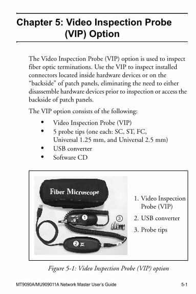
MT9090A/MU909011A Network Master User’s Guide 5-1
Chapter 5: Video Inspection Probe (VIP) Option
The Video Inspection Probe (VIP) option is used to inspect fiber optic terminations. Use the VIP to inspect installed connectors located inside hardware devices or on the “backside” of patch panels, eliminating the need to either disassemble hardware devices prior to inspection or access the backside of patch panels.
The VIP option consists of the following:
• Video Inspection Probe (VIP)• 5 probe tips (one each: SC, ST, FC,
Universal 1.25 mm, and Universal 2.5 mm)• USB converter• Software CD
Figure 5-1: Video Inspection Probe (VIP) option
1.
2.
3.
Video Inspection Probe (VIP)
USB converter
Probe tips
1
2
3
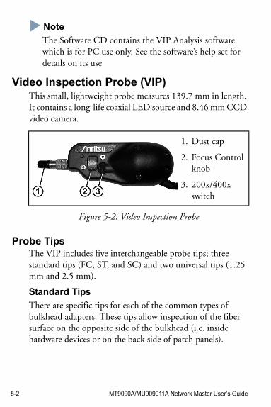
5-2 MT9090A/MU909011A Network Master User’s Guide
NoteNote
The Software CD contains the VIP Analysis software which is for PC use only. See the software’s help set for details on its use
Video Inspection Probe (VIP)This small, lightweight probe measures 139.7 mm in length. It contains a long-life coaxial LED source and 8.46 mm CCD video camera.
1.
2.
3.
Dust cap
Focus Control knob
200x/400x switch
Figure 5-2: Video Inspection Probe
Probe TipsThe VIP includes five interchangeable probe tips; three standard tips (FC, ST, and SC) and two universal tips (1.25 mm and 2.5 mm).
Standard Tips
There are specific tips for each of the common types of bulkhead adapters. These tips allow inspection of the fiber surface on the opposite side of the bulkhead (i.e. inside hardware devices or on the back side of patch panels).
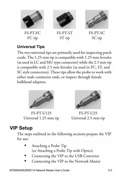
MT9090A/MU909011A Network Master User’s Guide 5-3
Universal Tips
The two universal tips are primarily used for inspecting patch cords. The 1.25 mm tip is compatible with 1.25 mm ferrules (as used in LC and MU type connector) while the 2.5 mm tip is compatible with 2.5 mm ferrules (as used in FC, ST, and SC style connectors). These tips allow the probe to work with either male connector ends, or inspect through female bulkhead adapters.
VIP SetupThe steps outlined in the following sections prepare the VIP for use:
• Attaching a Probe Tip(or Attaching a Probe Tip with Optics)
• Connecting the VIP to the USB Converter• Connecting the VIP to the Network Master
FS-PT-FCFC tip
FS-PT-STST tip
FS-PT-SCSC tip
FS-PT-U125Universal 1.25 mm tip
FS-PT-U25Universal 2.5 mm tip
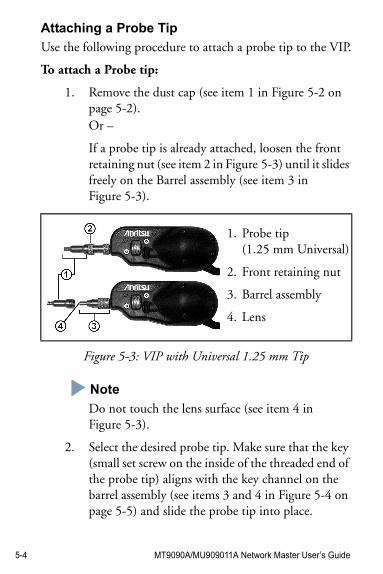
5-4 MT9090A/MU909011A Network Master User’s Guide
Attaching a Probe Tip
Use the following procedure to attach a probe tip to the VIP.
To attach a Probe tip:
1. Remove the dust cap (see item 1 in Figure 5-2 on page 5-2).Or –
If a probe tip is already attached, loosen the front retaining nut (see item 2 in Figure 5-3) until it slides freely on the Barrel assembly (see item 3 in Figure 5-3).
Figure 5-3: VIP with Universal 1.25 mm Tip
Note
Do not touch the lens surface (see item 4 in Figure 5-3).
2. Select the desired probe tip. Make sure that the key (small set screw on the inside of the threaded end of the probe tip) aligns with the key channel on the barrel assembly (see items 3 and 4 in Figure 5-4 on page 5-5) and slide the probe tip into place.
1.
2.
3.
4.
Probe tip(1.25 mm Universal)
Front retaining nut
Barrel assembly
Lens
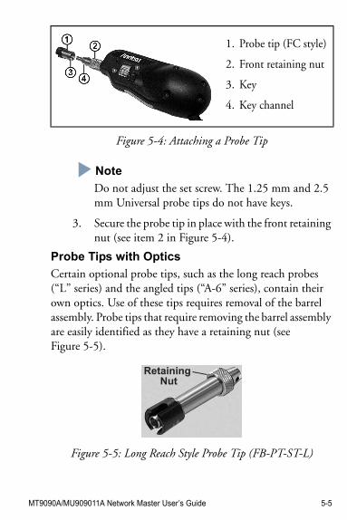
MT9090A/MU909011A Network Master User’s Guide 5-5
Figure 5-4: Attaching a Probe Tip
Note
Do not adjust the set screw. The 1.25 mm and 2.5 mm Universal probe tips do not have keys.
3. Secure the probe tip in place with the front retaining nut (see item 2 in Figure 5-4).
Probe Tips with Optics
Certain optional probe tips, such as the long reach probes (“L” series) and the angled tips (“A-6” series), contain their own optics. Use of these tips requires removal of the barrel assembly. Probe tips that require removing the barrel assembly are easily identified as they have a retaining nut (see Figure 5-5).
Figure 5-5: Long Reach Style Probe Tip (FB-PT-ST-L)
1.
2.
3.
4.
Probe tip (FC style)
Front retaining nut
Key
Key channel
Retaining Nut
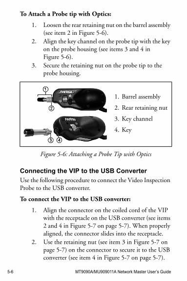
5-6 MT9090A/MU909011A Network Master User’s Guide
To Attach a Probe tip with Optics:
1. Loosen the rear retaining nut on the barrel assembly (see item 2 in Figure 5-6).
2. Align the key channel on the probe tip with the key on the probe housing (see items 3 and 4 in Figure 5-6).
3. Secure the retaining nut on the probe tip to the probe housing.
Figure 5-6: Attaching a Probe Tip with Optics
Connecting the VIP to the USB Converter
Use the following procedure to connect the Video Inspection Probe to the USB converter.
To connect the VIP to the USB converter:
1. Align the connector on the coiled cord of the VIP with the receptacle on the USB converter (see items 2 and 4 in Figure 5-7 on page 5-7). When properly aligned, the connector slides into the receptacle.
2. Use the retaining nut (see item 3 in Figure 5-7 on page 5-7) on the connector to secure it to the USB converter (see item 4 in Figure 5-7 on page 5-7).
1.
2.
3.
4.
Barrel assembly
Rear retaining nut
Key channel
Key
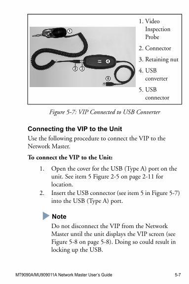
MT9090A/MU909011A Network Master User’s Guide 5-7
Figure 5-7: VIP Connected to USB Converter
Connecting the VIP to the Unit
Use the following procedure to connect the VIP to the Network Master.
To connect the VIP to the Unit:
1. Open the cover for the USB (Type A) port on the unit. See item 5 Figure 2-5 on page 2-11 for location.
2. Insert the USB connector (see item 5 in Figure 5-7) into the USB (Type A) port.
Note
Do not disconnect the VIP from the Network Master until the unit displays the VIP screen (see Figure 5-8 on page 5-8). Doing so could result in locking up the USB.
1.
2.
3.
4.
5.
Video Inspection Probe
Connector
Retaining nut
USBconverter
USBconnector
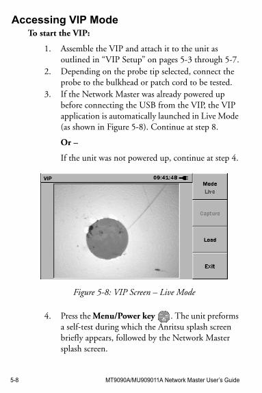
5-8 MT9090A/MU909011A Network Master User’s Guide
Accessing VIP ModeTo start the VIP:
1. Assemble the VIP and attach it to the unit as outlined in “VIP Setup” on pages 5-3 through 5-7.
2. Depending on the probe tip selected, connect the probe to the bulkhead or patch cord to be tested.
3. If the Network Master was already powered up before connecting the USB from the VIP, the VIP application is automatically launched in Live Mode (as shown in Figure 5-8). Continue at step 8.
Or –
If the unit was not powered up, continue at step 4.
Figure 5-8: VIP Screen – Live Mode
4. Press the Menu/Power key . The unit preforms a self-test during which the Anritsu splash screen briefly appears, followed by the Network Master splash screen.
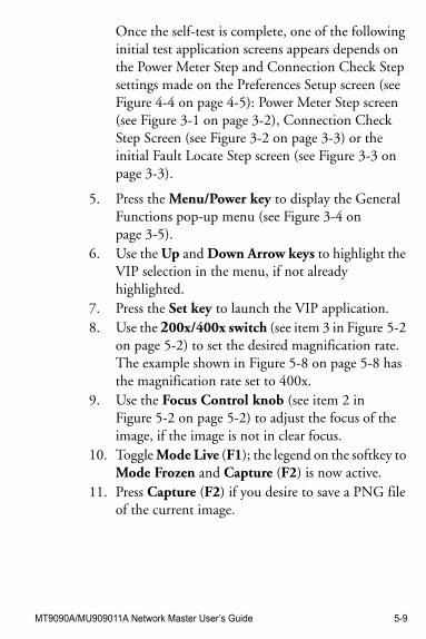
MT9090A/MU909011A Network Master User’s Guide 5-9
Once the self-test is complete, one of the following initial test application screens appears depends on the Power Meter Step and Connection Check Step settings made on the Preferences Setup screen (see Figure 4-4 on page 4-5): Power Meter Step screen (see Figure 3-1 on page 3-2), Connection Check Step Screen (see Figure 3-2 on page 3-3) or the initial Fault Locate Step screen (see Figure 3-3 on page 3-3).
5. Press the Menu/Power key to display the General Functions pop-up menu (see Figure 3-4 on page 3-5).
6. Use the Up and Down Arrow keys to highlight the VIP selection in the menu, if not already highlighted.
7. Press the Set key to launch the VIP application.8. Use the 200x/400x switch (see item 3 in Figure 5-2
on page 5-2) to set the desired magnification rate. The example shown in Figure 5-8 on page 5-8 has the magnification rate set to 400x.
9. Use the Focus Control knob (see item 2 in Figure 5-2 on page 5-2) to adjust the focus of the image, if the image is not in clear focus.
10. Toggle Mode Live (F1); the legend on the softkey to Mode Frozen and Capture (F2) is now active.
11. Press Capture (F2) if you desire to save a PNG file of the current image.
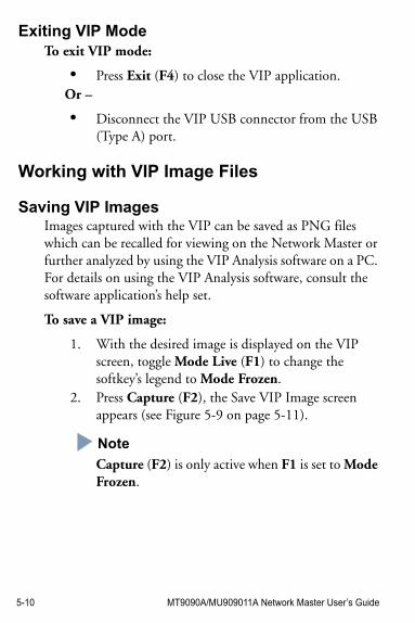
5-10 MT9090A/MU909011A Network Master User’s Guide
Exiting VIP ModeTo exit VIP mode:
• Press Exit (F4) to close the VIP application.Or –
• Disconnect the VIP USB connector from the USB (Type A) port.
Working with VIP Image Files
Saving VIP ImagesImages captured with the VIP can be saved as PNG files which can be recalled for viewing on the Network Master or further analyzed by using the VIP Analysis software on a PC. For details on using the VIP Analysis software, consult the software application’s help set.
To save a VIP image:
1. With the desired image is displayed on the VIP screen, toggle Mode Live (F1) to change the softkey’s legend to Mode Frozen.
2. Press Capture (F2), the Save VIP Image screen appears (see Figure 5-9 on page 5-11).
Note
Capture (F2) is only active when F1 is set to Mode Frozen.
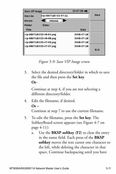
MT9090A/MU909011A Network Master User’s Guide 5-11
Figure 5-9: Save VIP Image screen
3. Select the desired directory/folder in which to save the file and then press the Set key.Or-
Continue at step 4, if you are not selecting a different directory/folder.
4. Edit the filename, if desired.Or – Continue at step 7 to use the current filename.
5. To edit the filename, press the Set key. The SoftkeyBoard screen appears (see Figure 4-7 on page 4-11):a. Use the BKSP softkey (F2) to clear the entry
in the name field. Each press of the BKSP softkey moves the text cursor one character to the left, while deleting the character in that space. Continue backspacing until you have
5-12 MT9090A/MU909011A Network Master User’s Guide
deleted all or as much of the current name as desired.
b. Use the Left/Right/Up/Down Arrow keys to highlight the desired letter in the character matrix.
c. Press the Set key to add the highlighted letter to the name field.
Note
To access numbers and symbols, press Mode (F1):
- the first key press opens Number mode
- the second key press opens Symbol mode
- the third key press returns to Alphabet mode.
d. Repeat steps 5b and 5c to complete editing the filename.
6. When the filename is completed, press OK (F4). The file is saved with the new name and the unit returns to the Save VIP Image screen.
7. Press Save (F1) to save the file.
Loading a VIP ImageVIP PNG files can be loaded on the Network Master from mass storage. This provides a method of visually checking the condition of a fiber optic termination to a previously saved PNG.
To load a VIP image:
1. Launch the VIP application from General Functions pop-up menu (see Figure 3-4 on page 3-5), if it is not already running.
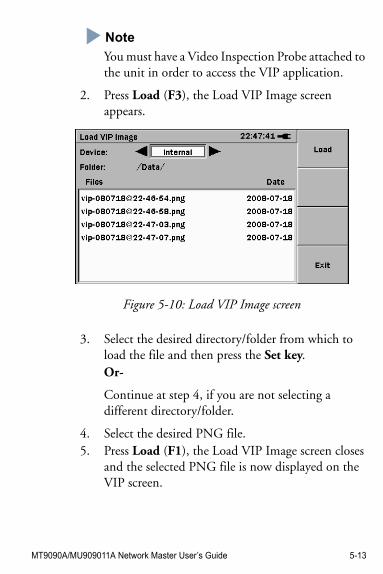
MT9090A/MU909011A Network Master User’s Guide 5-13
Note
You must have a Video Inspection Probe attached to the unit in order to access the VIP application.
2. Press Load (F3), the Load VIP Image screen appears.
Figure 5-10: Load VIP Image screen
3. Select the desired directory/folder from which to load the file and then press the Set key.Or-
Continue at step 4, if you are not selecting a different directory/folder.
4. Select the desired PNG file.5. Press Load (F1), the Load VIP Image screen closes
and the selected PNG file is now displayed on the VIP screen.
5-14 MT9090A/MU909011A Network Master User’s Guide
Mass Storage File OperationsThe mass storage file operations are can not be accessed while in VIP mode. See “Exiting VIP Mode” on page 5-10 for details.
Once the VIP application is closed, the follow file operations are available via the Mass Storage – File Operation screen (see Figure 3-12 on page 3-19).
• “Creating a New Folder”, see page 3-19• “Deleting a File or Folder”, see page 3-20• “Deleting Multiple Files or Folders”, see page 3-21• “Copying a File or Folder”, see page 3-22• “Copying Multiple Files or Folders”, see page 3-23• “Renaming a File or Folder”, see page 3-25
MT9090A/MU909011A Network Master User’s Guide 6-1
Chapter 6: Updating Firmware
The unit’s application software can be updated by the user by uploading the latest firmware released by Anritsu. The firmware file has a BBM file extension.
Updating the FirmwareUse the following procedure to update the unit’s firmware.
CAUTION !Always use the AC Charger/Adapter to power the unit when performing a firmware update.
To update the firmware:
1. Copy the BBM file, furnished by Anritsu, to a USB memory stick (conforming to USB 1.1).
2. Connect the USB memory stick to the USB (Type A) port on the unit.
3. Hold down the F1 key while powering up the unit (press the Menu/Power key).
Note
You can release the Menu/Power key once the Anritsu splash screen appears, but continue to hold down F1 until the initial Firmware Update screen is displayed (see Figure 6-1 on page 6-2).
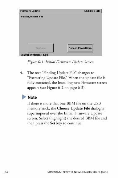
6-2 MT9090A/MU909011A Network Master User’s Guide
Figure 6-1: Initial Firmware Update Screen
4. The text “Finding Update File” changes to “Extracting Update File.” When the update file is fully extracted, the Installing new Firmware screen appears (see Figure 6-2 on page 6-3).
Note
If there is more that one BBM file on the USB memory stick, the Choose Update File dialog is superimposed over the Initial Firmware Update screen. Select (highlight) the desired BBM file and then press the Set key to continue.
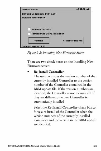
MT9090A/MU909011A Network Master User’s Guide 6-3
Figure 6-2: Installing New Firmware Screen
There are two check boxes on the Installing New Firmware screen:
• Re-Install Controller – The unit compares the version number of the currently installed Controller to the version number of the Controller contained in the BBM update file. If the version numbers are identical, the Controller is not re-installed. If they are different, the new Controller is automatically installed
Select the Re-Install Controller check box to force a re-install of the Controller when the version numbers of the currently installed Controller and the version in the BBM update are identical.
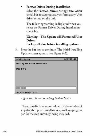
6-4 MT9090A/MU909011A Network Master User’s Guide
• Format Drives During Installation –Select the Format Drives During Installation check box to automatically re-format any User drives set up on the unit.
The following warning is displayed when you select the Format Drives During Installation check box:
Warning -- This Update will Format All User Drives.Backup all data before installing updates.
5. Press the Set key to continue. The initial Installing Update screen appears (see Figure 6-3).
Figure 6-3: Initial Installing Update Screen
The screen displays a count-down of the number of steps for the update installation, as well as a progress bar for the step currently being installed.
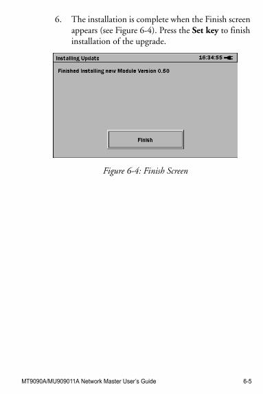
MT9090A/MU909011A Network Master User’s Guide 6-5
6. The installation is complete when the Finish screen appears (see Figure 6-4). Press the Set key to finish installation of the upgrade.
Figure 6-4: Finish Screen

6-6 MT9090A/MU909011A Network Master User’s Guide
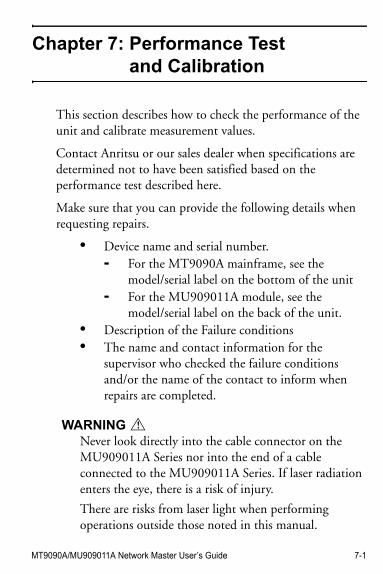
MT9090A/MU909011A Network Master User’s Guide 7-1
Chapter 7: Performance Test and Calibration
This section describes how to check the performance of the unit and calibrate measurement values.
Contact Anritsu or our sales dealer when specifications are determined not to have been satisfied based on the performance test described here.
Make sure that you can provide the following details when requesting repairs.
• Device name and serial number.- For the MT9090A mainframe, see the
model/serial label on the bottom of the unit- For the MU909011A module, see the
model/serial label on the back of the unit.• Description of the Failure conditions• The name and contact information for the
supervisor who checked the failure conditions and/or the name of the contact to inform when repairs are completed.
WARNING !
Never look directly into the cable connector on the MU909011A Series nor into the end of a cable connected to the MU909011A Series. If laser radiation enters the eye, there is a risk of injury.
There are risks from laser light when performing operations outside those noted in this manual.
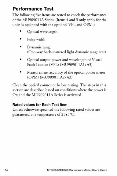
7-2 MT9090A/MU909011A Network Master User’s Guide
Performance TestThe following five items are tested to check the performance of the MU909011A Series. (Items 4 and 5 only apply for the units is equipped with the optional VFL and OPM.)
• Optical wavelength
• Pulse width
• Dynamic range (One-way back-scattered light dynamic range test)
• Optical output power and wavelength of Visual Fault Locator (VFL) (MU909011A1 / A3)
• Measurement accuracy of the optical power meter (OPM) (MU909011A2 / A3)
Clean the optical connector before testing. The steps in this section are described based on conditions where the power is On and the MU909011A Series is activated.
Rated values for Each Test ItemUnless otherwise specified the following rated values are guaranteed at a temperature of 25±5°C.
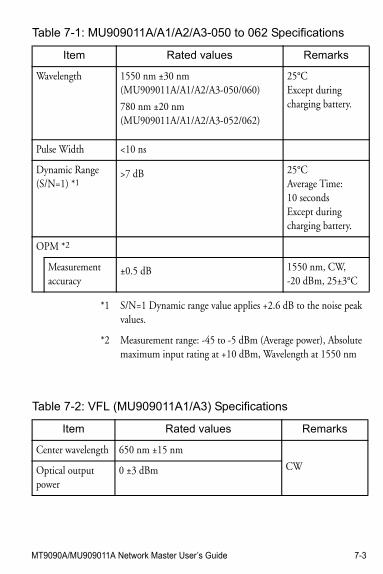
MT9090A/MU909011A Network Master User’s Guide 7-3
Table 7-1: MU909011A/A1/A2/A3-050 to 062 Specifications
Item Rated values Remarks
Wavelength 1550 nm ±30 nm(MU909011A/A1/A2/A3-050/060)
780 nm ±20 nm(MU909011A/A1/A2/A3-052/062)
25°CExcept during charging battery.
Pulse Width <10 ns
Dynamic Range(S/N=1) *1
>7 dB 25°CAverage Time:10 secondsExcept during charging battery.
OPM *2
Measurementaccuracy
±0.5 dB 1550 nm, CW, -20 dBm, 25±3°C
*1 S/N=1 Dynamic range value applies +2.6 dB to the noise peak values.
*2 Measurement range: -45 to -5 dBm (Average power), Absolute maximum input rating at +10 dBm, Wavelength at 1550 nm
Table 7-2: VFL (MU909011A1/A3) Specifications
Item Rated values Remarks
Center wavelength 650 nm ±15 nm
CWOptical output power
0 ±3 dBm
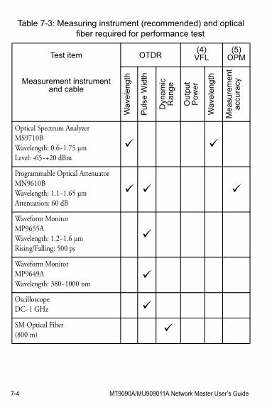
7-4 MT9090A/MU909011A Network Master User’s Guide
Table 7-3: Measuring instrument (recommended) and optical fiber required for performance test
Test item OTDR(4)
VFL(5)
OPM
Measurement instrument and cable
Wa
vele
ngth
Pul
se W
idth
Dyn
am
icR
ang
e
Ou
tpu
tP
ower
Wa
vele
ngth
Me
asu
rem
en
tac
cura
cy
Optical Spectrum AnalyzerMS9710BWavelength: 0.6~1.75 µmLevel: -65~+20 dBm
Programmable Optical AttenuatorMN9610BWavelength: 1.1~1.65 µmAttenuation: 60 dB
Waveform MonitorMP9655AWavelength: 1.2~1.6 µmRising/Falling: 500 ps
Waveform MonitorMP9649AWavelength: 380~1000 nm
OscilloscopeDC~1 GHz
SM Optical Fiber(800 m)
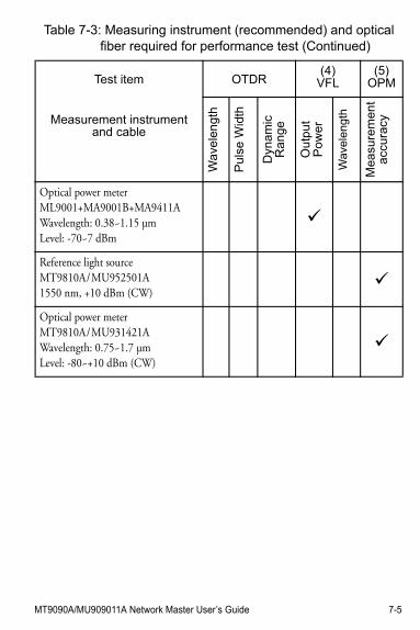
MT9090A/MU909011A Network Master User’s Guide 7-5
Measurement instrument and cable
Wa
vele
ng
th
Pu
lse
Wid
th
Dyn
am
icR
an
ge
Ou
tpu
tP
ow
er
Wav
elen
gth
Mea
sure
men
ta
ccur
acy
Optical power meterML9001+MA9001B+MA9411AWavelength: 0.38~1.15 µmLevel: -70~7 dBm
Reference light sourceMT9810A / MU952501A1550 nm, +10 dBm (CW)
Optical power meterMT9810A / MU931421AWavelength: 0.75~1.7 µmLevel: -80~+10 dBm (CW)
Table 7-3: Measuring instrument (recommended) and optical fiber required for performance test (Continued)
Test item OTDR(4)
VFL(5)
OPM
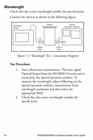
7-6 MT9090A/MU909011A Network Master User’s Guide
WavelengthCheck that the center wavelength satisfies the specifications.
Connect the devices as shown in the following figure.
Figure 7-1: Wavelength Test – Connection Diagram
Test Procedure:
1. Start a Real-time measurement. The laser signal Optical Output from the MU909011A series unit is received by the optical spectrum analyzer. To measure the wavelength, adjust following on the optical spectrum analyzer: measurement level, wavelength resolution and then select the appropriate RMS.
2. Check that the center wavelength satisfies the specification.
MU909011
Series
Optical
Spectrum Analyzer
Optical
Variable Attenuator
Optical
Fiber
Optical
Fiber
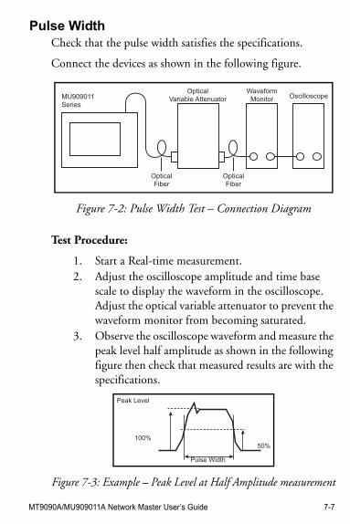
MT9090A/MU909011A Network Master User’s Guide 7-7
Pulse WidthCheck that the pulse width satisfies the specifications.
Connect the devices as shown in the following figure.
Figure 7-2: Pulse Width Test – Connection Diagram
Test Procedure:
1. Start a Real-time measurement.2. Adjust the oscilloscope amplitude and time base
scale to display the waveform in the oscilloscope. Adjust the optical variable attenuator to prevent the waveform monitor from becoming saturated.
3. Observe the oscilloscope waveform and measure the peak level half amplitude as shown in the following figure then check that measured results are with the specifications.
Figure 7-3: Example – Peak Level at Half Amplitude measurement
MU909011
Series
Waveform
Monitor OscilloscopeOptical
Variable Attenuator
Optical
Fiber
Optical
Fiber
Peak Level
Pulse Width
100%
50%
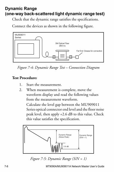
7-8 MT9090A/MU909011A Network Master User’s Guide
Dynamic Range(one-way back-scattered light dynamic range test)
Check that the dynamic range satisfies the specifications.
Connect the devices as shown in the following figure.
Figure 7-4: Dynamic Range Test – Connection Diagram
Test Procedure:
1. Start the measurement.2. When measurement is complete, move the
waveform display and read the following values from the measurement waveform.Calculate the level gap between the MU909011 Series optical connector end level and the floor noise peak level, then apply +2.6 dB to this value. Check this value satisfies the specification.
Figure 7-5: Dynamic Range (S/N = 1)
MU909011
Series
SM Optical Fiber
(800 m)
Far End: Grease for connection
Dynamic Range
(Noise Peak)
2.6 dB
Dynamic Range
(S/N = 1)
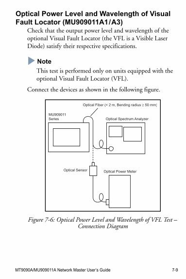
MT9090A/MU909011A Network Master User’s Guide 7-9
Optical Power Level and Wavelength of Visual Fault Locator (MU909011A1 / A3)
Check that the output power level and wavelength of the optional Visual Fault Locator (the VFL is a Visible Laser Diode) satisfy their respective specifications.
NoteNote
This test is performed only on units equipped with the optional Visual Fault Locator (VFL).
Connect the devices as shown in the following figure.
Figure 7-6: Optical Power Level and Wavelength of VFL Test – Connection Diagram
MU909011
Series
Optical Fiber (< 2 m, Bending radius ≥ 50 mm)
Optical Spectrum Analyzer
Optical Sensor Optical Power Meter
7-10 MT9090A/MU909011A Network Master User’s Guide
Test Procedure:
1. Select the VFL and then set its output mode to CW. See “To use the Visual Fault Locator:” on page 3-7 for details.
2. Measure the center wavelength using optical spectrum analyzer and the optical output power level using optical power meter respectively. Check that the output power level and wavelength of VFL satisfy their respective specifications.
Note
The output power level and wavelength test is performed with the Visual Fault Locator (VFL) set to CW (continuous wave) mode. Do not perform these tests with the VFL set to MOD (modulated mode).
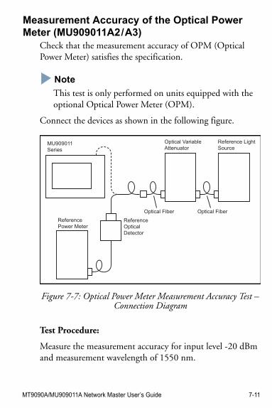
MT9090A/MU909011A Network Master User’s Guide 7-11
Measurement Accuracy of the Optical Power Meter (MU909011A2 / A3)
Check that the measurement accuracy of OPM (Optical Power Meter) satisfies the specification.
NoteNote
This test is only performed on units equipped with the optional Optical Power Meter (OPM).
Connect the devices as shown in the following figure.
Figure 7-7: Optical Power Meter Measurement Accuracy Test – Connection Diagram
Test Procedure:
Measure the measurement accuracy for input level -20 dBm and measurement wavelength of 1550 nm.
Optical Fiber Optical Fiber
MU909011
Series
Reference
Power MeterReference
Optical
Detector
Optical Variable
Attenuator
Reference Light
Source
7-12 MT9090A/MU909011A Network Master User’s Guide
1. Connect the optical variable attenuator and reference optical sensor.
2. Adjust the level to -20.00 dBm using the variable attenuator.
3. Connect the optical variable attenuator and MU909011 Series.
4. Check the value of optical power meter is -20.0 ±0.5 dBm.
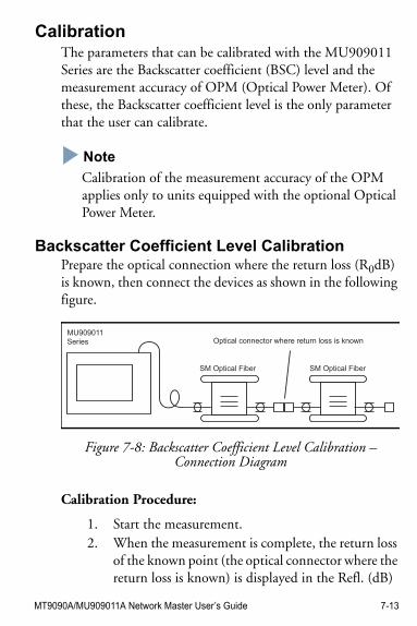
MT9090A/MU909011A Network Master User’s Guide 7-13
CalibrationThe parameters that can be calibrated with the MU909011 Series are the Backscatter coefficient (BSC) level and the measurement accuracy of OPM (Optical Power Meter). Of these, the Backscatter coefficient level is the only parameter that the user can calibrate.
NoteNote
Calibration of the measurement accuracy of the OPM applies only to units equipped with the optional Optical Power Meter.
Backscatter Coefficient Level CalibrationPrepare the optical connection where the return loss (R0dB) is known, then connect the devices as shown in the following figure.
Figure 7-8: Backscatter Coefficient Level Calibration – Connection Diagram
Calibration Procedure:
1. Start the measurement.2. When the measurement is complete, the return loss
of the known point (the optical connector where the return loss is known) is displayed in the Refl. (dB)
MU909011
Series
SM Optical Fiber SM Optical Fiber
Optical connector where return loss is known
7-14 MT9090A/MU909011A Network Master User’s Guide
column of the Event table. This value is assumed as R1dB.
3. Calculate the difference between R1dB and R0dB and then set the backscatter coefficient (BSC) value so that the measured reflectance equals the known reflectance (R0dB).
4. Restart the measurement to confirm the return loss is equal to the R0dB value.
Optical Power Meter CalibrationPlease contact Anritsu for calibration of the OPM measurement accuracy. To maintain the performance of this parameter, we recommend that MU909011 Series units are calibrated once a year.
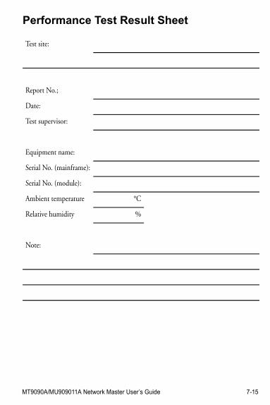
MT9090A/MU909011A Network Master User’s Guide 7-15
Performance Test Result Sheet
Test site:
Report No.;
Date:
Test supervisor:
Equipment name:
Serial No. (mainframe):
Serial No. (module):
Ambient temperature °C
Relative humidity %
Note:
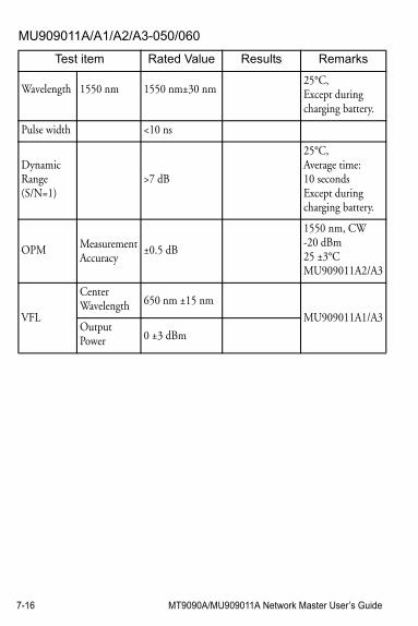
7-16 MT9090A/MU909011A Network Master User’s Guide
MU909011A/A1/A2/A3-050/060
Test item Rated Value Results Remarks
Wavelength 1550 nm 1550 nm±30 nm25°C,Except during charging battery.
Pulse width <10 ns
DynamicRange(S/N=1)
>7 dB
25°C,Average time: 10 secondsExcept during charging battery.
OPM Measurement Accuracy
±0.5 dB
1550 nm, CW-20 dBm25 ±3°CMU909011A2/A3
VFL
Center Wavelength 650 nm ±15 nm
MU909011A1/A3Output Power 0 ±3 dBm
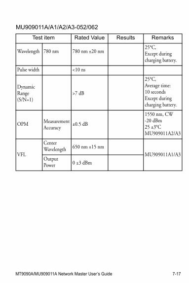
MT9090A/MU909011A Network Master User’s Guide 7-17
MU909011A/A1/A2/A3-052/062
Test item Rated Value Results Remarks
Wavelength 780 nm 780 nm ±20 nm25°C,Except during charging battery.
Pulse width <10 ns
DynamicRange(S/N=1)
>7 dB
25°C,Average time: 10 secondsExcept during charging battery.
OPM Measurement Accuracy
±0.5 dB
1550 nm, CW-20 dBm25 ±3°CMU909011A2/A3
VFL
Center Wavelength 650 nm ±15 nm
MU909011A1/A3Output Power 0 ±3 dBm

7-18 MT9090A/MU909011A Network Master User’s Guide
MT9090A/MU909011A Network Master User’s Guide 8-1
Chapter 8: Maintenance
Daily MaintenanceBe sure to turn off the power before performing daily maintenance.
Panel surface dirt
When the external surfaces become dirty, or when using the Network Master in dusty locations, etc., or before long-term storage, clean off any soiling using a soft cloth slightly moistened with neutral detergent.
Screen surface dirt
NEVER clean with organic solvents, such as benzene, thinners, toluene, etc. Use a soft dry cloth or a cloth slightly moistened with ethanol to clean off any grease marks, fingerprints, etc.
Loose screws
Use a coin or flat-blade screwdriver to tighten screws.
8-2 MT9090A/MU909011A Network Master User’s Guide
Notes On StorageRemove any dust or dirt adhering to the equipment before storage.
Remove batteries from the Network Master.
Pack accessories, such as adapters and CD-ROM, etc., into the accessories box and store it with the main frame.
Avoid storing in these places:
• In direct sunlight• Dusty places• Damp places where condensation may occur on the
equipment's surface• Places with active/corrosive gases• Places where the equipment may be oxidized• Places where there is a risk of vibration or
mechanical shock• Places where there is a risk of packing boxes falling
over• Places where the temperature and humidity are as
follows:Temperature: –30°C or lower, or 70°C or higher
Humidity: 95% or higher
Recommended storage conditions
It is recommended that the equipment be stored in a place that meets the ambient conditions suggested above, plus the following conditions, if it is not to be used for a long period of time:
MT9090A/MU909011A Network Master User’s Guide 8-3
• Temperature: 5°C to 45°C• Humidity: 40% to 80%• Little temperature and humidity fluctuations within
1 day
Transporting and DisposalThis section describes the precautions to observe when transporting and disposing of the main frame at the end of its useful life.
Repackaging
Use the original shipping materials, or an approved optional transit case, when repacking the unit for transport. Repack according to the following procedure when the original shipping materials (or a transit case) are not available.
1. Procure a corrugated cardboard, wooden, or aluminum box large enough to pack in cushioning material around the unit.
2. Wrap the main frame in some material such as plastic sheeting that will prevent entry of dust and water.
3. Place the unit into the box. 4. Pack soft materials around the main frame so that it
cannot slide around inside the packing box. 5. Secure the outside of the box with packaging cord,
adhesive tape, bands, or other such implements.
8-4 MT9090A/MU909011A Network Master User’s Guide
Transporting
In addition to preventing vibration as much as possible, transport under conditions meeting the storage conditions outlined above.
Disposal
When the main frame has reached the end of its useful life, dispose of it in accordance with local environmental regulations.
Before disposal, dismantle or physically destroy any non-volatile memory media in the Network Master to ensure that data in memory cannot be recovered by third parties.

MT9090A/MU909011A Network Master User’s Guide 8-5

8-6 MT9090A/MU909011A Network Master User’s Guide
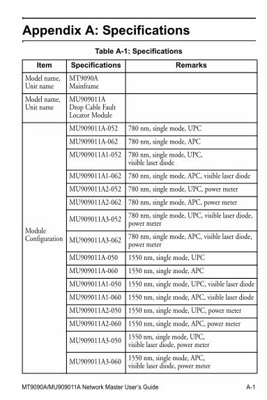
MT9090A/MU909011A Network Master User’s Guide A-1
Appendix A: Specifications
Table A-1: Specifications
Item Specifications Remarks
Model name, Unit name
MT9090AMainframe
Model name, Unit name
MU909011ADrop Cable Fault Locator Module
ModuleConfiguration
MU909011A-052 780 nm, single mode, UPC
MU909011A-062 780 nm, single mode, APC
MU909011A1-052 780 nm, single mode, UPC, visible laser diode
MU909011A1-062 780 nm, single mode, APC, visible laser diode
MU909011A2-052 780 nm, single mode, UPC, power meter
MU909011A2-062 780 nm, single mode, APC, power meter
MU909011A3-052 780 nm, single mode, UPC, visible laser diode, power meter
MU909011A3-062 780 nm, single mode, APC, visible laser diode, power meter
MU909011A-050 1550 nm, single mode, UPC
MU909011A-060 1550 nm, single mode, APC
MU909011A1-050 1550 nm, single mode, UPC, visible laser diode
MU909011A1-060 1550 nm, single mode, APC, visible laser diode
MU909011A2-050 1550 nm, single mode, UPC, power meter
MU909011A2-060 1550 nm, single mode, APC, power meter
MU909011A3-050 1550 nm, single mode, UPC, visible laser diode, power meter
MU909011A3-060 1550 nm, single mode, APC, visible laser diode, power meter
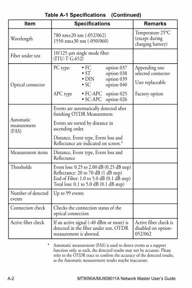
A-2 MT9090A/MU909011A Network Master User’s Guide
Table A-1 Specifications (Continued)
Item Specifications Remarks
Wavelength780 nm±20 nm (-052/062)1550 nm±30 nm (-050/060)
Temperature 25°C (except during charging battery)
Fiber under test 10/125 µm single mode fiber (ITU-T G.652)
Optical connector
PC type:
APC type
• FC• ST• DIN• SC
• FC-APC• SC-APC
option 037option 038option 039option 040
option 025option 026
Appending one selected connector
User replaceable
Factory option
Automatic measurement(FAS)
Events are automatically detected after finishing OTDR Measurement.
Events are sorted by distance in ascending order.
Distance, Event type, Event loss and Reflectance are indicated on screen.*
Measurement items Distance, Event type, Event loss and Reflectance
Thresholds Event loss: 0.25 to 2.00 dB (0.25 dB step)Reflectance: 20 to 70 dB (1 dB step)End of Fiber: 1.0 to 5.0 dB (0.1 dB step)Total loss: 0.1 to 5.0 dB (0.1 dB step)
Number of detected events
Up to 99 events
Connection check Checks the connection status of the optical connection
Active fiber check If an active signal (-40 dBm or more) is detected in the fiber under test, OTDR measurement is aborted.
Active fiber check is disabled on option-052/062
* Automatic measurement (FAS) is used to detect events as a support function only, as such, the detected results may not be accurate. Please refer to the OTDR trace to confirm the accuracy of the detected results, as the Automatic measurement results maybe inaccurate.
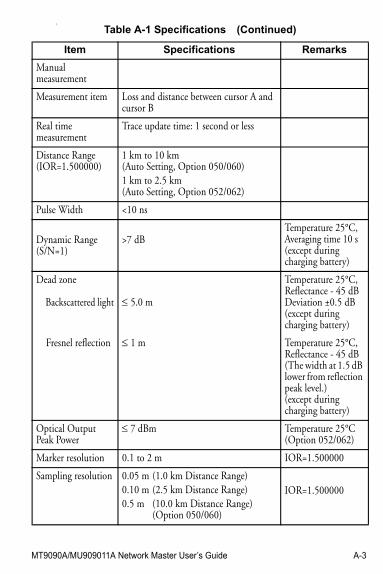
MT9090A/MU909011A Network Master User’s Guide A-3
3
Table A-1 Specifications (Continued)
Item Specifications Remarks
Manualmeasurement
Measurement item Loss and distance between cursor A and cursor B
Real time measurement
Trace update time: 1 second or less
Distance Range(IOR=1.500000)
1 km to 10 km(Auto Setting, Option 050/060)1 km to 2.5 km(Auto Setting, Option 052/062)
Pulse Width <10 ns
Dynamic Range(S/N=1)
>7 dBTemperature 25°C,Averaging time 10 s(except during charging battery)
Dead zone
Backscattered light
Fresnel reflection
5.0 m
1 m
Temperature 25°C,Reflectance - 45 dBDeviation ±0.5 dB(except during charging battery)
Temperature 25°C,Reflectance - 45 dB(The width at 1.5 dB lower from reflection peak level.)(except during charging battery)
Optical OutputPeak Power
7 dBm Temperature 25°C(Option 052/062)
Marker resolution 0.1 to 2 m IOR=1.500000
Sampling resolution 0.05 m (1.0 km Distance Range)0.10 m (2.5 km Distance Range)0.5 m (10.0 km Distance Range)
(Option 050/060)
IOR=1.500000
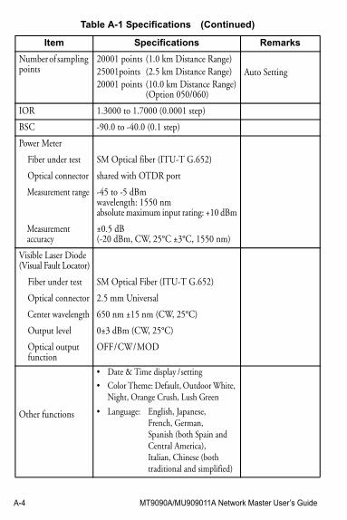
A-4 MT9090A/MU909011A Network Master User’s Guide
Number of sampling points
20001 points (1.0 km Distance Range) 25001points (2.5 km Distance Range)20001 points (10.0 km Distance Range)
(Option 050/060)
Auto Setting
IOR 1.3000 to 1.7000 (0.0001 step)
BSC -90.0 to -40.0 (0.1 step)
Power Meter
Fiber under test
Optical connector
Measurement range
Measurement accuracy
SM Optical fiber (ITU-T G.652)
shared with OTDR port
-45 to -5 dBmwavelength: 1550 nmabsolute maximum input rating: +10 dBm
±0.5 dB(-20 dBm, CW, 25°C ±3°C, 1550 nm)
Visible Laser Diode(Visual Fault Locator)
Fiber under test
Optical connector
Center wavelength
Output level
Optical output function
SM Optical Fiber (ITU-T G.652)
2.5 mm Universal
650 nm ±15 nm (CW, 25°C)
0±3 dBm (CW, 25°C)
OFF / CW / MOD
Other functions
• Date & Time display / setting
• Color Theme: Default, Outdoor White, Night, Orange Crush, Lush Green
• Language: English, Japanese, French, German, Spanish (both Spain andCentral America),Italian, Chinese (bothtraditional and simplified)
Table A-1 Specifications (Continued)
Item Specifications Remarks
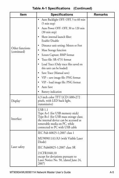
MT9090A/MU909011A Network Master User’s Guide A-5
Other functions(continued)
• Auto Backlight OFF: OFF, 5 to 60 min (5 min step)
• Auto Power OFF: OFF, 30 to 120 min (30 min step)
• Show internal launch fiber: Enable / Disable
• Distance unit setting: Meters or Feet
• Mass Storage function
• Screen Capture: BMP format
• Trace file: SR-4731 format
• Load Trace (Only trace files saved on this unit can be loaded)
• Save Trace (Manual save)
• VIP – save image file: PNG format
• VIP – load image file: PNG format
• Auto Save
• Battery indication
Display4.3 inch color TFT LCD (480×272 pixels, with LED back light, transmissive)
Interface
USB 1.1Type A×1 (for USB memory stick)Type B×1 (for USB mass storage class; the internal device can be accessed as removable media on PC, while connected to PC with USB cable
Laser safety
IEC Pub 60825-1;2007 class 1
MU909011A1/A3 (with Visible Laser Diode)
IEC Pub60825-1;2007 class 3R
21CFR1040,10except for deviations pursuant toLaser Notice No. 50, (dated June 24, 2007)
Table A-1 Specifications (Continued)
Item Specifications Remarks
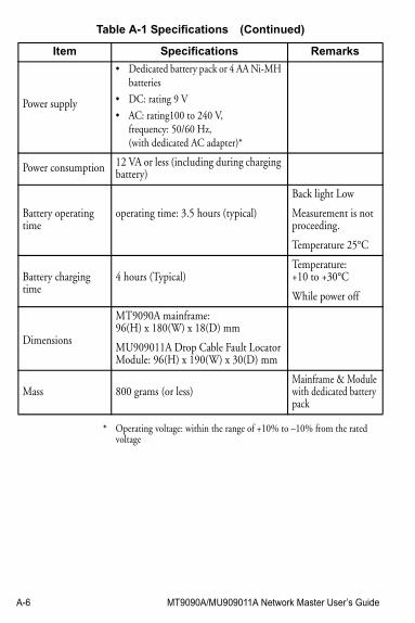
A-6 MT9090A/MU909011A Network Master User’s Guide
Power supply
• Dedicated battery pack or 4 AA Ni-MH batteries
• DC: rating 9 V
• AC: rating100 to 240 V,frequency: 50/60 Hz,(with dedicated AC adapter)*
Power consumption 12 VA or less (including during charging battery)
Battery operating time
operating time: 3.5 hours (typical)
Back light Low
Measurement is not proceeding.
Temperature 25°C
Battery charging time
4 hours (Typical)Temperature: +10 to +30°C
While power off
Dimensions
MT9090A mainframe:96(H) x 180(W) x 18(D) mm
MU909011A Drop Cable Fault Locator Module: 96(H) x 190(W) x 30(D) mm
Mass 800 grams (or less)Mainframe & Modulewith dedicated battery pack
* Operating voltage: within the range of +10% to –10% from the rated voltage
Table A-1 Specifications (Continued)
Item Specifications Remarks
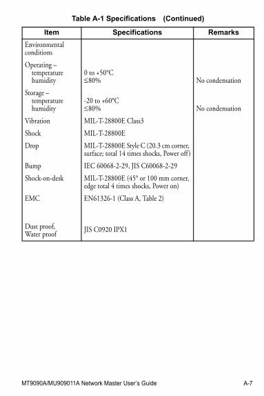
MT9090A/MU909011A Network Master User’s Guide A-7
Environmental conditions
Operating – temperature humidity
Storage – temperature humidity
Vibration
Shock
Drop
Bump
Shock-on-desk
EMC
Dust proof, Water proof
0 to +50°C80%
-20 to +60°C80%
MIL-T-28800E Class3
MIL-T-28800E
MIL-T-28800E Style C (20.3 cm corner, surface; total 14 times shocks, Power off )
IEC 60068-2-29, JIS C60068-2-29
MIL-T-28800E (45° or 100 mm corner, edge total 4 times shocks, Power on)
EN61326-1 (Class A, Table 2)
JIS C0920 IPX1
No condensation
No condensation
Table A-1 Specifications (Continued)
Item Specifications Remarks
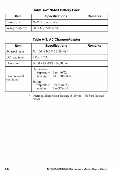
A-8 MT9090A/MU909011A Network Master User’s Guide
Table A-2: Ni-MH Battery Pack
Item Specifications Remarks
Battery type Ni-MH Battery pack
Voltage, Capacity DC 4.8 V, 2700 mAh
Table A-3: AC Charger/Adapter
Item Specifications Remarks
AC rated input AC 100 to 240 V, 50 / 60 Hz *
DC rated input 9 Vdc, 1.7 A
Dimensions 74(H) x 43.5(W) x 34(D) mm
Environmental conditions
Operation – temperature: humidity:
Storage – temperature: humidity:
0 to +40°C, 20 to 80% R.H.
-40 to +80°C, 0 to 90% R.H.
* Operating voltage: within the range of +10% to –10% from the rated voltage
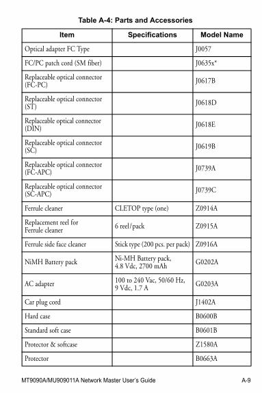
MT9090A/MU909011A Network Master User’s Guide A-9
Table A-4: Parts and Accessories
Item Specifications Model Name
Optical adapter FC Type J0057
FC/PC patch cord (SM fiber) J0635x*
Replaceable optical connector(FC-PC) J0617B
Replaceable optical connector (ST) J0618D
Replaceable optical connector (DIN) J0618E
Replaceable optical connector (SC) J0619B
Replaceable optical connector (FC-APC) J0739A
Replaceable optical connector (SC-APC) J0739C
Ferrule cleaner CLETOP type (one) Z0914A
Replacement reel for Ferrule cleaner 6 reel / pack Z0915A
Ferrule side face cleaner Stick type (200 pcs. per pack) Z0916A
NiMH Battery pack Ni-MH Battery pack,4.8 Vdc, 2700 mAh G0202A
AC adapter 100 to 240 Vac, 50/60 Hz,9 Vdc, 1.7 A G0203A
Car plug cord J1402A
Hard case B0600B
Standard soft case B0601B
Protector & softcase Z1580A
Protector B0663A
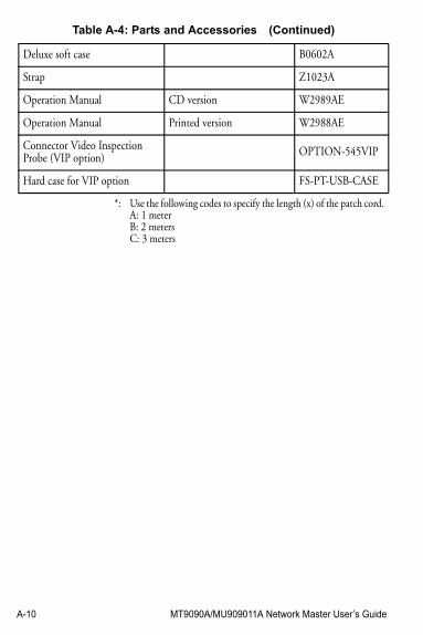
A-10 MT9090A/MU909011A Network Master User’s Guide
Deluxe soft case B0602A
Strap Z1023A
Operation Manual CD version W2989AE
Operation Manual Printed version W2988AE
Connector Video Inspection Probe (VIP option) OPTION-545VIP
Hard case for VIP option FS-PT-USB-CASE
*: Use the following codes to specify the length (x) of the patch cord.A: 1 meterB: 2 metersC: 3 meters
Table A-4: Parts and Accessories (Continued)
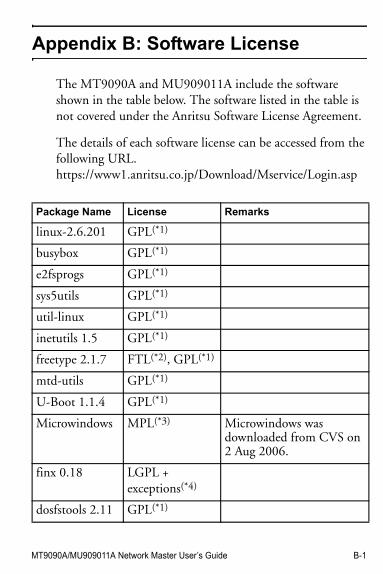
MT9090A/MU909011A Network Master User’s Guide B-1
Appendix B: Software License
The MT9090A and MU909011A include the software shown in the table below. The software listed in the table is not covered under the Anritsu Software License Agreement.
The details of each software license can be accessed from the following URL.https://www1.anritsu.co.jp/Download/Mservice/Login.asp
Package Name License Remarks
linux-2.6.201 GPL(*1)
busybox GPL(*1)
e2fsprogs GPL(*1)
sys5utils GPL(*1)
util-linux GPL(*1)
inetutils 1.5 GPL(*1)
freetype 2.1.7 FTL(*2), GPL(*1)
mtd-utils GPL(*1)
U-Boot 1.1.4 GPL(*1)
Microwindows MPL(*3) Microwindows was downloaded from CVS on 2 Aug 2006.
finx 0.18 LGPL + exceptions(*4)
dosfstools 2.11 GPL(*1)
B-2 MT9090A/MU909011A Network Master User’s Guide
portman 5 beta Other(*5)
Package Name License Remarks
MT9090A/MU909011A Network Master User’s Guide IX-1
Index
Bbattery fluid warning viiibattery pack
disposal procedure xx
Ccalibration seal viicaution symbol ivCE marking xxiClass 1 Laser safety ixClass 3R Laser safety xconformity markings
CE xxiC-tick xxiv
council directive 2002/96/EC xx
crossed-out Wheeled Bin symbol xx
C-tick marking xxiv
Ddisposal procedure xx
Eelectrical safety xv
EMC xviiequipment certificate xviiexport management xxexternal storage media
USB memory xvi
IIEC 61010 Standard v
LLaser radiation markings xivLaser radiation warning viLaser safety
Class 1 ixClass 3R xLaser radiation markings
xivLaser Safety label viLCD
warning ixLiquid Crystal Display
warning ix
OOut xxvOut-of-warranty repairs xxv
IX-2 MT9090A/MU909011A Network Master User’s Guide
Pperformance-guarantee seal viiprohibited operation symbol
iv
Rrecycle symbols ivRepair warning virepairs xxvReturn Materials
Authorization xxvRMA number xxv
Ssafety precaution symbol ivsafety symbols iii
caution ivprohibited operation ivsafety precaution ivwarning iv, v
Service and Sales offices xixsymbols - safety iii
Ttechnical support xxv
UUSB memory xvi
Wwarning symbol iv, vwarranty
Out-of-warranty repairs xxvWEEE directive xxWheeled Bin symbol xx